series 42 axial piston pumps technical information system, redundant to the hydrostatic...
TRANSCRIPT

8 11022637 • Rev. CF • January 2013
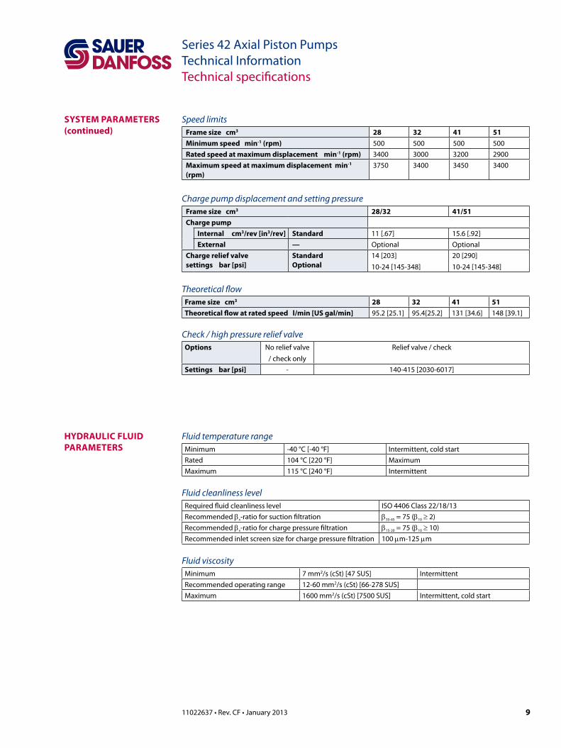
Series 42 Axial Piston PumpsTechnical InformationTechnical specifications
system sPeCifiCations
General specificationsPump type In-line, axial piston, positive displacement pumps
including cradle swashplate and servo controlDirection of input rotation Clockwise or counterclockwiseRecommended installation position Pump installation recommended with control position
on the top or side. Consult Sauer-Danfoss for non conformance guidelines. The housing must always be filled with hydraulic fluid.
filtration configuration Suction or charge pressure filtrationother system requirements Independent braking system, suitable reservoir and heat
exchanger.
Hardware featuresPump configuration Single variable pump
frame size cm3 28 32 41 51Displacement cm3[in3] 28 [1.71] 31.8 [1.94] 40.9 [2.50] 51 [3.11]weight kgf [lbf] 34.5 [76] 34.5 [76] 42 [92] 42 [92]mass moment of inertia kg•m2 [lbf•ft2]
0.0018 [0.0013]
0.0019 [0.0013]
0.0036 [0.0027]
0.0038 [0.0028]
type of front mounting flange (sae flange size per sae J744)
SAE B
Port connections SAE-twin ports, radial
system pressure regulation bar [psi]
140-415 [2030-6017]
140-345 [2030-5003]
140-415 [2030-6017]
140-345 [2030-5003]
Displacement limiters Option
input shaft options Splined, Round Straight Key
auxiliary mounting pad (sae pad per sae J744)
SAE A (9 tooth and 11 tooth)SAE B (13 tooth and 15 tooth)
Control options MDC, FNR, NFPH, NFPE, HC-EDC, EDC
filtration configuration Suction or charge pressure filtration
loop flushing Option
Case pressureRated pressure bar [psi] 3 [44]maximum pressure (cold start) bar [psi] 5 [73]
Pressure limitsframe size cm3 28 32 41 51maximum working pressure* bar [psi] 400 [5800] 350 [5075] 400 [5800] 350 [5075]maximum pressure bar [psi] 450 [6525] 400 [5800] 450 [6525] 400 [5800]
* Operation above maximum working pressure is permissible with Sauer-Danfoss application approval.
Inlet pressureContinuous pressure bar (absolute) [in Hg vacuum] 0.8 [6]minimum pressure (cold start) bar (absolute) [in Hg vacuum] 0.2 [24]
system PaRameteRs
911022637 • Rev. CF • January 2013
Series 42 Axial Piston PumpsTechnical InformationTechnical specifications
HyDRauliC fluiD PaRameteRs
Speed limitsframe size cm3 28 32 41 51minimum speed min-1 (rpm) 500 500 500 500Rated speed at maximum displacement min-1 (rpm) 3400 3000 3200 2900maximum speed at maximum displacement min-1 (rpm)
3750 3400 3450 3400
Charge pump displacement and setting pressure frame size cm3 28/32 41/51Charge pump
internal cm3/rev [in3/rev] standard 11 [.67] 15.6 [.92]external — Optional Optional
Charge relief valve settings bar [psi]
standardoptional
14 [203]10-24 [145-348]
20 [290]10-24 [145-348]
Theoretical flowframe size cm3 28 32 41 51theoretical flow at rated speed l/min [us gal/min] 95.2 [25.1] 95.4[25.2] 131 [34.6] 148 [39.1]
Check / high pressure relief valveoptions No relief valve
/ check onlyRelief valve / check
settings bar [psi] - 140-415 [2030-6017]
Fluid temperature rangeMinimum -40 °C [-40 °F] Intermittent, cold startRated 104 °C [220 °F] MaximumMaximum 115 °C [240 °F] Intermittent
Fluid cleanliness levelRequired fluid cleanliness level ISO 4406 Class 22/18/13Recommended βx-ratio for suction filtration β35-45 = 75 (β10 ≥ 2)Recommended βx-ratio for charge pressure filtration β15-20 = 75 (β10 ≥ 10)Recommended inlet screen size for charge pressure filtration 100 µm-125 µm
Fluid viscosityMinimum 7 mm2/s (cSt) [47 SUS] IntermittentRecommended operating range 12-60 mm2/s (cSt) [66-278 SUS]Maximum 1600 mm2/s (cSt) [7500 SUS] Intermittent, cold start
system PaRameteRs(continued)
10 11022637 • Rev. CF • January 2013
Series 42 Axial Piston PumpsTechnical InformationOperating parameters
speed limitsRated speed is the speed limit we recommend at full power condition and is the highest value at which you can expect normal life.
Maximum speed is the highest operating speed we permit. You cannot operate above this speed without risk of immediate failure and loss of drive line power and hydrostatic braking capacity (which may create a hazard). In mobile applications, you must apply this pump with a speed speed below the stated maximum. Consult Bln-9884, Pressure and Speed Limits, when determining speed limits for a particular application.
inlet pressureControl charge pump inlet conditions to achieve expected life and performance. Ensure a continuous inlet pressure of not less than 0.8 bar absolute (not more than 6 in Hg vacuum). Normal pressures less than 0.7 bar absolute (greater than 9 in Hg vacuum) indicate inadequate inlet design or a restricted filter. Pressures less than 0.7 bar absolute (greater than 9 in Hg vac) during cold start are possible, but should improve quickly as the fluid warms. Never exceed the maximum inlet vacuum.
theoretical outputThe theoretical maximum flow at rated speed is a simple function of pump displacement and speed. This is a good gauge for sizing a companion motor. This does not take into account losses due to leakage or variations in displacement.
system RequiRements independent braking systemW Warningunintended vehicle or machine movement hazard. The loss of hydrostatic drive line power, in any mode of operation (forward, neutral, or reverse) may cause the system to lose hydrostatic braking capacity. You must provide a braking system, redundant to the hydrostatic transmission, sufficient to stop and hold the vehicle or machine in the event of hydrostatic drive power loss.
ReservoirDesign the system to accommodate maximum volume changes during all system operating modes and to promote de-aeration of the fluid as it passes through the tank.
Minimum reservoir volume is 5/8 of the maximum charge pump flow per minute with a minimum fluid volume equal to 1/2 of the maximum charge pump flow per minute. At the maximum return flow, this allows 30 seconds fluid dwell for removing entrained air. This is adequate for a closed reservoir (no breather) in most applications.
Position the reservoir outlet (pump inlet) above the bottom of the reservoir to take advantage of gravity separation and prevent large foreign particles from entering the charge inlet line. Use a 100 - 125 µm screen over the outlet port.
Position the reservoir inlet (fluid return) so that flow to the reservoir is discharged below the normal fluid level, and directed into the interior of the reservoir for maximum dwell and efficient de-aeration. Use a baffle (or baffles) between the inlet and outlet ports to promote de-aeration and reduce surging of the fluid.
system PaRameteRs

1111022637 • Rev. CF • January 2013
Series 42 Axial Piston PumpsTechnical InformationOperating parameters
Case pressureUnder normal operating conditions, the rated case pressure must not be exceeded.During cold start case pressure must be kept below maximum intermittent case pressure. Size drain plumbing accordingly.
system pressuresystem pressure is the differential pressure between high pressure system ports. Itis the dominant operating variable affecting hydraulic unit life. High system pressure, which results from high load, reduces expected life. Hydraulic unit life depends on the speed and normal operating, or weighted average, pressure that can only be determined from a duty cycle analysis.
application pressure - is the high pressure relief or pressure limiter setting normally defined within the order code of the pump. This is the applied system pressure at which the driveline generates the maximum calculated pull or torque in the application.
maximum working Pressure - is the highest recommended Application pressure.Maximum working pressure is not intended to be a continuous pressure. Propel systems with Application pressures at, or below, this pressure should yield satisfactory unit life given proper component sizing.
maximum pressure is the highest allowable Application pressure under anycircumstance. Application pressures above Maximum Working Pressure will only beconsidered with duty cycle analysis and factory approval.
minimum pressure must be maintained under all operating conditions to avoidcavitation.
All pressure limits are differential pressures referenced to low loop (charge) pressure. Subtract low loop pressure from gauge readings to compute the differential.
system PaRameteRs(continued)
12 11022637 • Rev. CF • January 2013
Series 42 Axial Piston PumpsTechnical InformationOperating parameters
temperature and viscosityEnsure the application satisfies temperature and viscosity requirements concurrently. The data shown in the tables on page 9, Hydraulic fluid parameters, assume petroleum-based fluids.
High temperature limits apply at the hottest point in the transmission, which is normally the case drain. Always run the pump at or below the continuous temperature. Never exceed maximum temperature.
Durability of transmission components is not affected by cold oil, but it may affect the ability of oil to flow and transmit power. Keep temperatures 16 °C [30 °F] above the pour point of the hydraulic fluid. The minimum temperature relates to physical properties of component materials.
For maximum unit efficiency and bearing life, keep fluid viscosity in the continuous viscosity range. During brief occasions of maximum ambient temperature and severe duty cycle operation, minimum viscosity may occur. The system should encounter maximum viscosity only at cold start.
Size heat exchangers to keep the fluid temperature and viscosity within these limits. Test the system to verify that these temperature limits are not exceeded.
Hydraulic fluidRatings and data are based on operating with hydraulic fluids containing inhibitors to prevent oxidation, rust, and foam. These fluids must possess good thermal and hydrolytic stability to prevent wear, erosion, and corrosion of the internal components. Fire resistant fluids are also suitable at modified operating conditions. Please see Sauer-Danfoss publication 520l0463, Hydraulic Fluids and Lubricants, Technical Information for more information.
Do not mix different types of hydraulic fluids. Contact your Sauer-Danfoss representative for more information on fluid selection. The following hydraulic fluids are suitable:
• Hydraulic Oil ISO 11 158 - HM (Seal compatibility and vane pump wear resistance per DIN 51 524-2 must be met)
• Hydraulic Oil ISO 11 158 - HV (Seal compatibility and vane pump wear resistance per DIN 51 524-3 must be met)
• Hydraulic Oil DIN 51 524-2 - HLP• Hydraulic Oil DIN 51 524-3 - HVLP • Automatic Transmission Fluid ATF A Suffix A (GM)• Automatic Transmission Fluid Dexron II (GM), which meets Allison C-3 and Caterpillar
TO-2 test• Automatic Transmission Fluid M2C33F and G (Ford)• Engine oils API Classification SL, SJ (for gasoline engines) and CI-4, CH-4, CG-4, CF-4
and CF (for diesel engines)• Super Tractor Oil Universal (STOU) special agricultural tractor fluid
HyDRauliC fluiD PaRameteRs
1311022637 • Rev. CF • January 2013
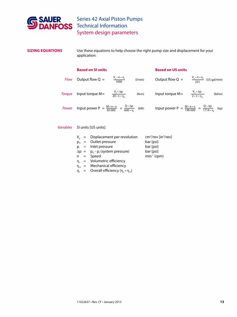
Series 42 Axial Piston PumpsTechnical InformationSystem design parameters
sizinG equations
Based on si units
Output flow Q = (l/min)
Input torque M = (N•m)
Input power P = = (kW)
Based on us units
Output flow Q = (US gal/min)
Input torque M = (lbf•in)
Input power P = = (hp)
SI units [US units]
Vg = Displacement per revolution cm3/rev [in3/rev]pO = Outlet pressure bar [psi]pi = Inlet pressure bar [psi]∆p = pO - pi (system pressure) bar [psi]n = Speed min-1 (rpm)ηv = Volumetric efficiencyηm = Mechanical efficiencyηt = Overall efficiency (ηv • ηm)
Variables
Vg • n • ηv
1000
Vg • ∆p20 • π • ηm
Q • ∆p600 • ηt
M • n • π30 000
Vg • n • ηv
231
Vg • ∆p2 • π • ηm
Q • ∆p1714 • ηt
M • n • π198 000
Use these equations to help choose the right pump size and displacement for your application:
Flow
Torque
Power

18 11022637 • Rev. CF • January 2013
Series 42 Axial Piston PumpsTechnical InformationSystem design parameters
HyDRauliC unit life Hydraulic unit life is the life expectancy of the hydraulic components. Hydraulic unit life is a function of speed and system pressure. Hwever, system pressure is the dominant operating variable. High pressure, which results from high load, reduces expected life.
Design the hydraulic system to a projected machine duty cycle. Know the expected percentages of time at various loads and speeds. Ask your Sauer-Danfoss representative to calculate an appropriate pressure based your hydraulic system design. If duty cycle data is not available, input power and pump displacement are used to calculate system pressure.
All pressure limits are differential pressures (referenced to charge pressure) and assume normal charge pressure.
Series 42 pumps will meet satisfactory life expectancy if applied within the parameters specified in this bulletin. For more detailed information on hydraulic unit life see BLN-9884, Pressure and Speed Limits.
effiCienCy GRaPHs The performance graph below left provides typical volumetric and overall efficiencies for Series 42 pumps. These efficiencies apply for all Series 42 pumps at maximum displacement.
The performance map below right provides typical pump overall efficiencies at various operating parameters. These efficiencies also apply for all Series 42 pumps at maximum displacement.
100
80
95
90
85
E�ci
ency
— %
0 25 50 75 100Speed, % of Rated Speed
Volumetric Efficiency 1 b 2500 psi]- 70 ar [
Volumetric Efficiency b 5000 psi]- 345 ar [
Overall Effic
500 psi]
iency - 170 bar [2
Overall Efficiency - 345 bar [5000 psi]
P100401E
5000
0
4000
3000
2000
1000
Syst
em P
ress
ure
0 25 50 75 100Speed, % of Rated Speed
psi350bar
300
250
200
150
100
50
0
88% 87%
85%
80%
P100402E
Pump performance as a function of operating speed at maximum displacement*
Pump performance at select operating parameters at maximum displacement*
* Assumes viscosity in the continuous range

20 11022637 • Rev. CF • January 2013
Series 42 Axial Piston PumpsTechnical InformationFeatures and options
Particular application conditions may require a more detailed review of charge pump sizing. System features and conditions that may invalidate the 10% of displacement rule include (but are not limited to):
• Operation at low input speeds (below 1500 rpm)• Shock loading• Excessively long system lines• Auxiliary flow requirements• Use of low speed, high torque motors
If a charge pump of sufficient capacity to meet the 10% of displacement rule is not available or if any of the above conditions exist, which could invalidate the 10% rule, contact your Sauer-Danfoss representative for application assistance.
You can find a charge pump sizing worksheet in Selection of Driveline Components, Bln-9885.
Charge pump sizing example: A system consists of a single Series 42 - 28 Variable Pump driving two Series 40 -M35 Fixed Motors:
TD = 28 + 35 + 35 = 98 cm3
CPD = 10 % x TD = 9.8 cm3
This requires a charge pump displacement of 9.8 cm3 [0.59 in³] or more. Sufficient charge flow for this application is provided by a 11 cm3 [0.67 in³] charge pump.
CHaRGe Relief valve The charge relief valve maintains charge pressure at a designated level. Series 42 pumps come with direct-acting poppet style charge relief valves. The valve setting is set at the factory. The setting is screw adjustable.
The charge pressure settings are nominal values and are based on the charge flow across the charge relief valve with a fluid viscosity of 28 mm2/s (cSt) [130 SUS] and a pump input speed of 1800 min-1(rpm). Actual charge pressure differs slightly from the nominal setting when different input speeds are used. The charge setting is a differential pressure (referenced to case pressure) and measured with the piston pump at zero swashplate angle (neutral). Charge pressure drops slightly when the pump is in stroke due to flow demands.
The charge pressure setting for pumps without an internal charge pump is set with an assumed charge flow of 19 l/min (5 US gal/min). These units must have adequate charge flow supplied to the charge inlet in order to maintain charge pressure at all times.
From ChargePump
To Low Sideof Working
Loop & ServoControl
To Case
P100392E
Charge relief valveC CautionIncorrect charge pressure settings may result in the inability to build required system pressure, inability to control pump, and/or inadequate loop flushing flows. Maintain correct charge pressure under all operating conditions.
CHaRGe PumP(continued)
2111022637 • Rev. CF • January 2013
Series 42 Axial Piston PumpsTechnical InformationFeatures and options
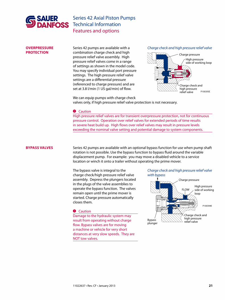
oveRPRessuRe PRoteCtion
Series 42 pumps are available with a combination charge check and high pressure relief valve assembly. High pressure relief valves come in a range of settings as shown in the model code. You may specify individual port pressure settings. The high pressure relief valve settings are a differential pressure (referenced to charge pressure) and are set at 3.8 l/min (1 US gal/min) of flow.
We can equip pumps with charge check valves only, if high pressure relief valve protection is not necessary.
C CautionHigh pressure relief valves are for transient overpressure protection, not for continuous pressure control. Operation over relief valves for extended periods of time results in severe heat build up. High flows over relief valves may result in pressure levels exceeding the nominal valve setting and potential damage to system components.
High pressureside of working loop
Charge check andhigh pressurerelief valve
Charge pressure
P100393E
Charge check and high pressure relief valve
Series 42 pumps are available with an optional bypass function for use when pump shaft rotation is not possible. Use the bypass function to bypass fluid around the variable displacement pump. For example: you may move a disabled vehicle to a service location or winch it onto a trailer without operating the prime mover.
The bypass valve is integral to the charge check/high pressure relief valve assembly. Depress the plungers located in the plugs of the valve assemblies to operate the bypass function. The valves remain open until the prime mover is started. Charge pressure automatically closes them.
C CautionDamage to the hydraulic system may result from operating without charge flow. Bypass valves are for moving a machine or vehicle for very short distances at very slow speeds. They are NOT tow valves.
ByPass valves
Charge pressure
High pressureside of working loop
Charge check andhigh pressurerelief valveBypass
plunger
FLOW
P100394E
Charge check and high pressure relief valve with bypass

2311022637 • Rev. CF • January 2013
Series 42 Axial Piston PumpsTechnical InformationFeatures and options
sPeeD sensoR Series 42 pumps are available with a speed sensor option for direct measurement of pump input speed.
A special magnetic speed ring is pressed onto the outside diameter of the cylinder block and a Hall effect pulse pickup sensor is located in the pump housing. The sensor accepts supply voltage and outputs a digital pulse signal in response to the speed of the ring. The output changes its high/low state as the north and south poles of the permanently magnetized speed ring pass by the face of the sensor. The digital signal is generated at frequencies suitable for microprocessor based controls.
This sensor operates with a supply voltage of 4.5 to 15 Vdc, and requires a current of 12 mA at 5.0 Vdc under no load. Maximum operating current is 20 mA at 5 Vdc. Maximum operating frequency is 15 kHz. Output voltage in high state (VOH) is sensor supply voltage minus 0.5 Vdc, minimum. Output voltage in low state (VOL) is 0.5 Vdc, maximum.
Contact your Sauer-Danfoss representative for production availability on specific pump frame sizes, or for special speed sensor options.
Speed sensor with Packard Weather-Pack connector (KPPG13408)
Connecting pin designation:Pin A : Supply voltagePin B : Speed signal, digital Pin C : Ground commonPin D : Direction of rotation
RedWhiteBlackGreen
A
BCD
Packard Weather-Pack4 pin
(Supplied Connector)
Mating ConnectorNo.: K03379
Id.-No.: 505341
P002108E
(200)
Technical data speed sensorsupply voltage1) 4.5-8.5 Vdcsupply voltage regulated
15 Vdc maximum
Required current 12 mA at 5 Vdc (no load)maximum current 20 mA at 5 Vdc and 1 Hzmaximum frequency
15 kHz
voltage “high” Supply voltage -0.5 Vdc minimum
voltage “low” 0.5 Vdc maximumtemperature range -40 to 110 °C [-40 to 230 °F]
1) It is not acceptable to energize the 4.5 - 8.5 Vdc speed sensor with 12 Vdc battery voltage; it must be energized by a regulated power supply. If it is desirable to energize the sensor with battery voltage, contact your Sauer-Danfoss representative for and optional speed sensor.
Speed ring dataframe size (cm3) 28/32 41 51Pulses/rev 41 47 47

24 11022637 • Rev. CF • January 2013
Series 42 Axial Piston PumpsTechnical InformationFeatures and options
sHaft oPtions Series 42 pumps are available with a variety of splined and tapered shaft ends. The accompanying table shows available shaft sizes and torque ratings. Maximum torque ratings are based on shaft torsional strength and assume a maximum of 200 000 load reversals.
Use ANSI B92.1 Class 5 mating splines for splined output shafts. Sauer-Danfoss external splines are modified Class 5 fillet root side fit. The external spline major diameter and circular tooth thickness dimensions are reduced in order to insure a clearance fit with the mating spline.
Shaft availability and torque rating *
shaft max. torque, 28/32 cm³ max. torque, 41/51 cm³13 tooth spline, 16/32 pitch 226 N•m [2000 in•lbf ] 226 N•m [2000 in•lbf ]15 tooth spline, 16/32 pitch 362 N•m [3200 in•lbf ] 362 N•m [3200 in•lbf ]19 tooth spline, 16/32 pitch — 734 N•m [6500 in•lbf ]Round Straight Key Ø25.4mm [1 in] 362 N•m [3200 in•lbf ] 362 N•m [3200 in•lbf ] **
* The limitations of these input shafts constrain the allowable auxiliary coupling torque. ** Not recommended for all options. Contact your Sauer-Danfoss representative.
auxiliaRy mountinG PaDs
Auxiliary mounting pads are available on all Series 42 pumps to mount auxiliary hydraulic pumps. We include a sealed (oil tight) shipping cover as standard equipment. The shipping cover seals case pressure and you can use it as a running cover if desired.
Since the auxiliary mounting pad operates under case pressure, you must use an O-ring to seal the auxiliary pump to the pad. The drive coupling is lubricated with oil from the main pump case.
Spline specifications and torque ratings are shown in the accompanying table.
Auxiliary pad1
Pad size Spline Minimum spline lengthmm [in]
Maximum torqueN•m [lbf•in]
SAE A 9 tooth16/32 pitch
13.5 [0.53] 107 [950]
SAE A special
11 tooth16/32 pitch
13.5 [0.53] 147 [1300]
SAE B 13 tooth16/32 pitch
14.2 [0.56] 248 [2200]
SAE B-B 15 tooth16/32 pitch
14.2 [0.56] 347 [3070]
• All mounting pads meet SAE J744 specifications.
• The sum of main and auxiliary pump torque must not exceed stated maximum.
• All torque values assume a 58 Rc shaft spline hardness on mating pump shaft. Maximum torque is based on maximum torsional strength and 200 000 load reversals.
• Applications with severe vibratory or high G-force (shock) loading may require additional structural support to prevent leaks or mounting flange damage. Refer to Mounting flange loads, page 16 for additional information.
1Allowable Auxiliary coupling torque is subject to limitations of the input shaft.

2511022637 • Rev. CF • January 2013
Series 42 Axial Piston PumpsTechnical InformationFeatures and options
This drawing provides the dimensions for the auxiliary pump mounting flange and shaft. Auxiliary pump mounting flanges and shafts with these dimensions are compatible with the auxiliary mounting pads on Series 42 pumps. For auxiliary pad dimensions, see Auxiliary mounting pads, page 56.
0¯ -0.05P(+.000)(-.002)
Spline Engagementfor Torque
E max.
MountingFlange
D max.
Cmax.
Bmax.
R 0.8 (.03)max.
Coupling
F min.
2.3 (.09)Cutter clearance
WithUndercut
WithoutUndercut
Auxiliary pump mating dimensionsPad Size P B C D E FSAE A mm [in] 82.55 [3.250] 8.1 [0.32] 12.7 [0.500] 44 [1.73] 15 [0.59] 13.5 [0.53]SAE B mm [in] 101.6 [4.000] 11.4 [0.45] 15.2 [0.60] 46 [1.81] 17.5 [0.69] 14.2 [0.56]
P001614E
ContRol seleCtion Series 42 pumps use a servo control system with a vairety of control options. Manual and Electric Displacement Controls (MDC, EDC and HC-EDC) are feedback controls that provide and maintain a set displacement for a given input. The MDC includes options for a Neutral Start Switch (NSS), backup alarm , and a solenoid override to neutral. Non-Feedback Proportional Electric or Hydraulic controls (NFPE, NFPH) and Forward-Neutral-Reverse (FNR) controls are available to control the pump without mechanical feedback.
All controls provide smooth, stepless positive control of the transmission in either direction. Optional servo supply and drain orifices are available for special response needs.
Typical control applicationsMachine Function MDC FNR NFPH NFPE HC-EDC EDCRoller / compactor Propel
Vibratory drive
Asphalt paver PropelConveyor drive
Skid steer loader Propel
Articulated loader Propel
Utility tractor Propel
Windrower Propel
Trencher PropelChain drive
Ag sprayer Propel
Specialized harvesters (sod, fruit, nut, etc.)
PropelAuxiliary drive
Commercial mower Popel
Rock drill Propel
Drill rig Drill drivePull down
Sweeper PropelFan
Aerial lift Propel
Fork lift Propel
Brush / stump cutter PropelCutter drive
Airport vehicle Propel
Dumper Propel
auxiliaRy mountinG PaDs (continued)