heavy duty hydrostatic piston pumps (aca) and motors (ace ...eaton heavy duty hydrostatic...
TRANSCRIPT
Heavy Duty Hydrostatic Transmissions
Series 1 Variable Displacement Piston Pumps (ACA) and Motors (ACE) Fixed Displacement Motors (HHD)
Peak pressure 480 bar (7000 psi) Displacement 64-125 cm3/r (3.9-7.6 in3/r)

eaton Heavy Duty Hydrostatic Transmissions Catalog E-TRHD-MC001-E2 July 2011 2
eaton Heavy Duty Hydrostatic Transmissions Catalog E-TRHD-MC001-E2 July 2011 3
Table of Contents
Heavy Duty Hydrostatic Transmissions ACA: Series 1 Variable Pump 4ACE: Variable Motor 5HHD: Fixed Motor 5
Model CodesACA: Series 1 Variable Pump Model Code 6HHD: Fixed Motor Model Code 11ACE: Variable Motor Model Code 13
Performance Performance – Pump 15Performance – Motor 16Performance – Charge Pump 17
Control OptionsPump Control – Electro-proportional with Swashplate Mechanical Feedback 18Pump Control – Electro-proportional with Swashplate Electronic Sensor and Mechanical Feedback 19Pump Control – Electric with Swashplate Electronic Sensor Feedback 20Other Pump and Motor Controls 26
DimensionsCharge Pump Dimensions 30Dimensions 32
Power Limiter Pumps and Integral Shuttle Valve Motors Features and Benefits 35Dimensions – Power Limiter Pump 36Dimensions – Integral Shuttle Motor 38
Heavy Duty Tandem Pumps Features and Benefits 40Dimensions – Tandem Pumps 41Application Information – Tandem Pumps 43
Heavy Duty Pumps with C-Pad Rear Mount Features and Benefits 44Dimensions – Pumps with C-Pad Rear Mount 45
Shaft and Port Dimensions – Shaft and Port 47Application Information 50
Description of Operation Description of Operation 53Description of Operation – Neutral 54Flow Description – Neutral 55Description of Operation – Forward/Reverse 56Flow Description – Forward/Reverse 57
Hydraulic Fluid Recommendations 58
eaton Heavy Duty Hydrostatic Transmissions Catalog E-TRHD-MC001-E2 July 2011 4
Variable Pump
Heavy Duty Hydrostatic Transmissions Features and Benefits
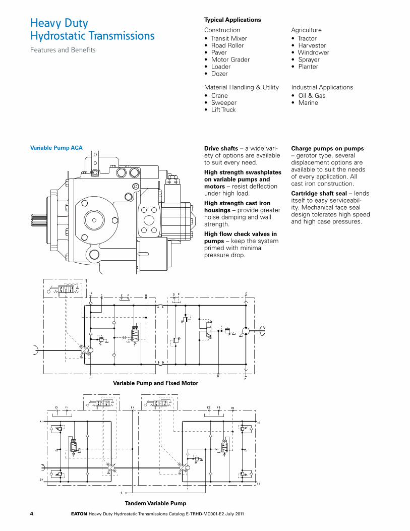
Drive shafts – a wide vari-ety of options are available to suit every need.
High strength swashplates on variable pumps and motors – resist deflection under high load.
High strength cast iron housings – provide greater noise damping and wall strength.
High flow check valves in pumps – keep the system primed with minimal pressure drop.
Charge pumps on pumps – gerotor type, several displacement options are available to suit the needs of every application. All cast iron construction.
Cartridge shaft seal – lends itself to easy serviceabil-ity. Mechanical face seal design tolerates high speed and high case pressures.
Variable Pump ACA
Variable Pump and Fixed Motor
Tandem Variable Pump
Construction • Transit Mixer• Road Roller• Paver• Motor Grader• Loader• Dozer
Agriculture • Tractor• Harvester• Windrower• Sprayer• Planter
Typical Applications
Industrial Applications• Oil & Gas• Marine
Material Handling & Utility• Crane• Sweeper• Lift Truck
eaton Heavy Duty Hydrostatic Transmissions Catalog E-TRHD-MC001-E2 July 2011 5
Heavy Duty Hydrostatic Transmissions Features and Benefits
Advanced cylinder barrel design – permits high speed and pressure.
Fixed clearance slipper hold down – on Models 39 through 64 allows oper-ation at high speed and reduces friction. Model 76 is a ball guide unit.
Pistons – have long engagement with cylinder bore resulting in low leakage.
Hydraulic servo control – provides low effort opera-tion with low control pres-sure. Large servo pistons hold swashplate position and provide damping.
Large case drain ports – minimize case back pressure.
Fixed Motor HDD
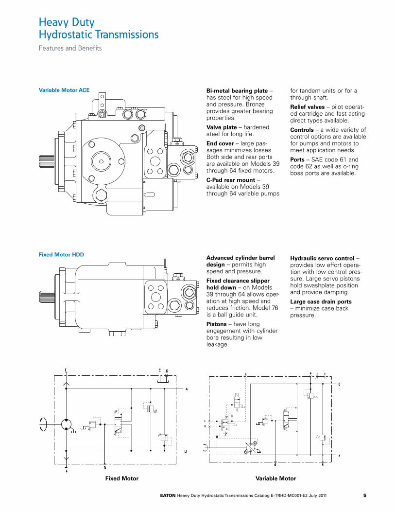
Variable Motor ACE Bi-metal bearing plate – has steel for high speed and pressure. Bronze provides greater bearing properties.
Valve plate – hardened steel for long life.
End cover – large pas-sages minimizes losses. Both side and rear ports are available on Models 39 through 64 fixed motors.
C-Pad rear mount – available on Models 39 through 64 variable pumps
for tandem units or for a through shaft.
Relief valves – pilot operat-ed cartridge and fast acting direct types available.
Controls – a wide variety of control options are available for pumps and motors to meet application needs.
Ports – SAE code 61 and code 62 as well as o-ring boss ports are available.
Variable Motor
Fixed Motor Variable Motor
eaton Heavy Duty Hydrostatic Transmissions Catalog E-TRHD-MC001-E2 July 2011 6
ACA 39 2 03 02 L 1 A C C EA A A A 2 C N A A 1 0 D A 15 0 0 B
6 7 12 19 332411 18 3210 17 3113 20 2514 21 2622 2723 281, 2, 3 4, 5 8, 9 15, 16 29,30
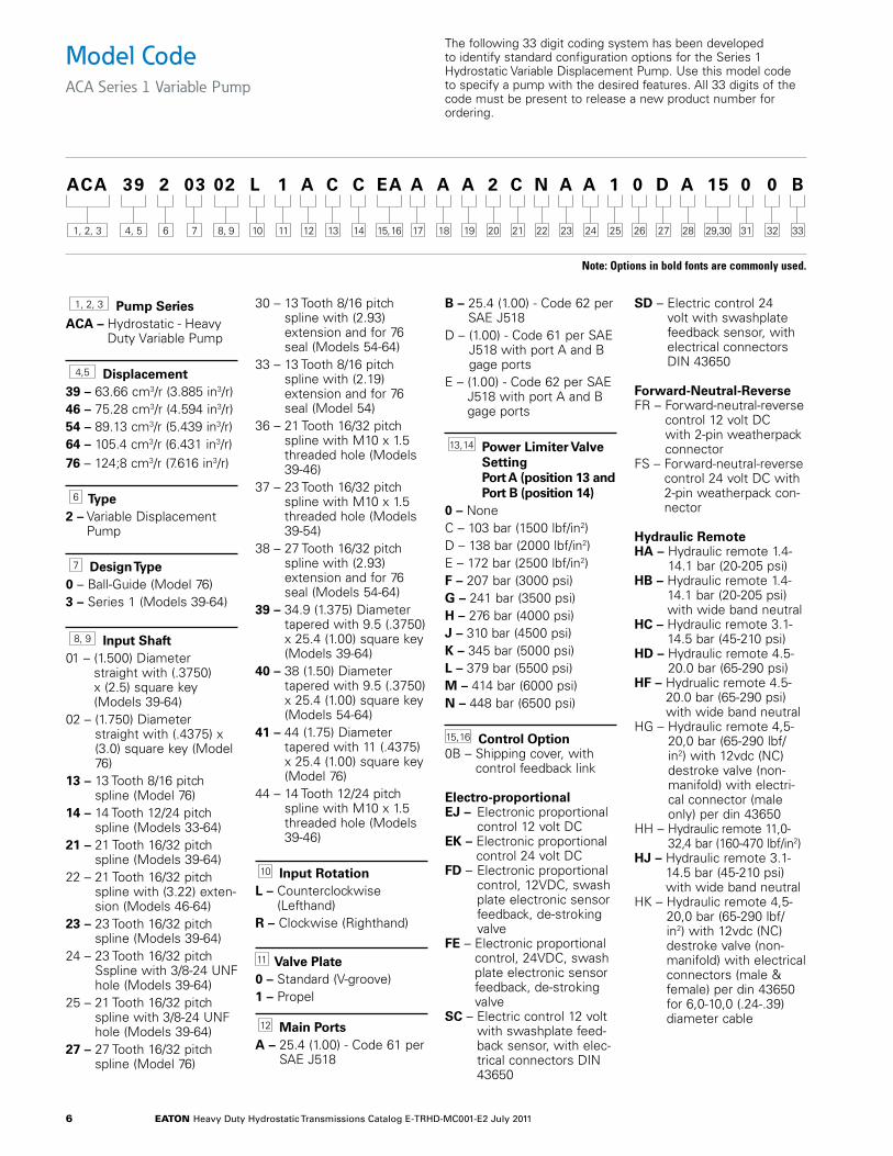
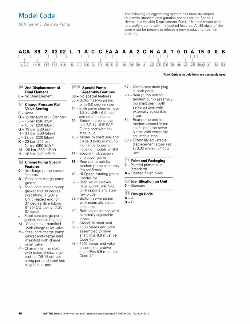
Model CodeACA Series 1 Variable Pump
The following 33 digit coding system has been developed to identify standard configuration options for the Series 1 Hydrostatic Variable Displacement Pump. Use this model code to specify a pump with the desired features. All 33 digits of the code must be present to release a new product number for ordering.
1, 2, 3 Pump SeriesACA – Hydrostatic - Heavy
Duty Variable Pump
4,5 Displacement 39 – 63.66 cm3/r (3.885 in3/r) 46 – 75.28 cm3/r (4.594 in3/r) 54 – 89.13 cm3/r (5.439 in3/r)64 – 105.4 cm3/r (6.431 in3/r)76 – 124;8 cm3/r (7.616 in3/r)
6 Type2 – Variable Displacement
Pump
7 Design Type0 – Ball-Guide (Model 76)3 – Series 1 (Models 39-64)
8, 9 Input Shaft 01 – (1.500) Diameter
straight with (.3750) x (2.5) square key (Models 39-64)
02 – (1.750) Diameter straight with (.4375) x (3.0) square key (Model 76)
13 – 13 Tooth 8/16 pitch spline (Model 76)
14 – 14 Tooth 12/24 pitch spline (Models 33-64)
21 – 21 Tooth 16/32 pitch spline (Models 39-64)
22 – 21 Tooth 16/32 pitch spline with (3.22) exten-sion (Models 46-64)
23 – 23 Tooth 16/32 pitch spline (Models 39-64)
24 – 23 Tooth 16/32 pitch Sspline with 3/8-24 UNF hole (Models 39-64)
25 – 21 Tooth 16/32 pitch spline with 3/8-24 UNF hole (Models 39-64)
27 – 27 Tooth 16/32 pitch spline (Model 76)
30 – 13 Tooth 8/16 pitch spline with (2.93) extension and for 76 seal (Models 54-64)
33 – 13 Tooth 8/16 pitch spline with (2.19) extension and for 76 seal (Model 54)
36 – 21 Tooth 16/32 pitch spline with M10 x 1.5 threaded hole (Models 39-46)
37 – 23 Tooth 16/32 pitch spline with M10 x 1.5 threaded hole (Models 39-54)
38 – 27 Tooth 16/32 pitch spline with (2.93) extension and for 76 seal (Models 54-64)
39 – 34.9 (1.375) Diameter tapered with 9.5 (.3750) x 25.4 (1.00) square key (Models 39-64)
40 – 38 (1.50) Diameter tapered with 9.5 (.3750) x 25.4 (1.00) square key (Models 54-64)
41 – 44 (1.75) Diameter tapered with 11 (.4375) x 25.4 (1.00) square key (Model 76)
44 – 14 Tooth 12/24 pitch spline with M10 x 1.5 threaded hole (Models 39-46)
10 Input RotationL – Counterclockwise
(Lefthand)R – Clockwise (Righthand)
11 Valve Plate0 – Standard (V-groove)1 – Propel
12 Main PortsA – 25.4 (1.00) - Code 61 per
SAE J518
B – 25.4 (1.00) - Code 62 per SAE J518
D – (1.00) - Code 61 per SAE J518 with port A and B gage ports
E – (1.00) - Code 62 per SAE J518 with port A and B gage ports
13, 14 Power Limiter Valve Setting Port A (position 13 and Port B (position 14)
0 – NoneC – 103 bar (1500 lbf/in2)D – 138 bar (2000 lbf/in2)E – 172 bar (2500 lbf/in2)F – 207 bar (3000 psi)G – 241 bar (3500 psi)H – 276 bar (4000 psi)J – 310 bar (4500 psi)K – 345 bar (5000 psi)L – 379 bar (5500 psi)M – 414 bar (6000 psi)N – 448 bar (6500 psi)
15, 16 Control Option0B – Shipping cover, with
control feedback link
Electro-proportionalEJ – Electronic proportional
control 12 volt DCEK – Electronic proportional
control 24 volt DCFD – Electronic proportional
control, 12VDC, swash plate electronic sensor feedback, de-stroking valve
FE – Electronic proportional control, 24VDC, swash plate electronic sensor feedback, de-stroking valve
SC – Electric control 12 volt with swashplate feed-back sensor, with elec-trical connectors DIN 43650
SD – Electric control 24 volt with swashplate feedback sensor, with electrical connectors DIN 43650
Forward-Neutral-Reverse FR – Forward-neutral-reverse
control 12 volt DC with 2-pin weatherpack connector
FS – Forward-neutral-reverse control 24 volt DC with 2-pin weatherpack con-nector
Hydraulic RemoteHA – Hydraulic remote 1.4-
14.1 bar (20-205 psi)HB – Hydraulic remote 1.4-
14.1 bar (20-205 psi) with wide band neutral
HC – Hydraulic remote 3.1-14.5 bar (45-210 psi)
HD – Hydraulic remote 4.5-20.0 bar (65-290 psi)
HF – Hydrualic remote 4.5-20.0 bar (65-290 psi) with wide band neutral
HG – Hydraulic remote 4,5-20,0 bar (65-290 lbf/in2) with 12vdc (NC) destroke valve (non-manifold) with electri-cal connector (male only) per din 43650
HH – Hydraulic remote 11,0-32,4 bar (160-470 lbf/in2)
HJ – Hydraulic remote 3.1-14.5 bar (45-210 psi) with wide band neutral
HK – Hydraulic remote 4,5-20,0 bar (65-290 lbf/in2) with 12vdc (NC) destroke valve (non-manifold) with electrical connectors (male & female) per din 43650 for 6,0-10,0 (.24-.39) diameter cable
Note: Options in bold fonts are commonly used.
eaton Heavy Duty Hydrostatic Transmissions Catalog E-TRHD-MC001-E2 July 2011 7
ACA 39 2 03 02 L 1 A C C EA A A A 2 C N A A 1 0 D A 15 0 0 B
6 7 12 19 332411 18 3210 17 3113 20 2514 21 2622 2723 281, 2, 3 4, 5 8, 9 15, 16 29,30
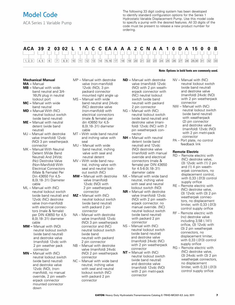
Model CodeACA Series 1 Variable Pump
The following 33 digit coding system has been developed to identify standard configuration options for the Series 1 Hydrostatic Variable Displacement Pump. Use this model code to specify a pump with the desired features. All 33 digits of the code must be present to release a new product number for ordering.
Mechanical ManualMA – ManualMB – Manual with wide
band neutral and 3/4-16UN plug in neutral lockout port
MC – Manual with wide band neutral
MD – Manual With (NC) neutral lockout switch (wide band neutral)
ME – Manual with neutral detent (wide band neutral)
MJ – Manual with destroke valve (manifold) 12vdc (NO) 3 pin weatherpack connector
MK – Manual With Neutral Detent (Wide Band Neutral) And 24Vdc (Nc) Destroke Valve (Non-Manifold) With Electrical Connectors (Male & Female) Per Din 43650 For 4,5-8,0(.18-.31) Diameter cable
ML – Manual with (NC) neutral lockout switch (wide band neutral) and 12vdc (NC) destroke valve (non-manifold) with electrical connec-tors (male & female) per DIN 43650 for 4,5-8,0(.18-.31) diameter cable
MM – Manual with (NO) neutral lockout switch (wide band neutral) and destroke valve (manifold) 12vdc with 2 pin weather pack connector
MN – Manual with (NC) neutral lockout switch (wide band neutral) and destroke valve 12vdc (NO), (non-manifold), no manual override, 2 pin weath-erpack connector mounted connector down
MP – Manual with destroke valve (non-manifold) 12vdc (NO), 3 pin packard connector mounted right angle up
MS – Manual with wide band neutral and 24vdc (NC) destroke valve (non-manifold) with electrical connectors (male & female) per din 43650 for 4,5-8,0(.18-.31) diameter cable
MT – With wide band neutral and inching valve with seal
MU – Manual with wide band neutral, inching valve with seal and neutral detent
MV – With wide band neu-tral, inching valve with seal and neutral lock-out switch (NC)
MW – Manual with destroke valve (manifold) 12vdc (NO) with 2 pin weatherpack connector
MZ – Manual with (NC) neutral lockout switch (wide band neutral) with packard 2 pin connector
NA – Manual with destroke valve (manifold) 12vdc (NO) 3 pin weatherpack connector and (NC) neutral lockout switch (wide band neutral) with packard 2 pin connector
NB – Manual with destroke valve (manifold) 24vdc (NO) 2 pin weatherpack connector
NC – Manual with wide band neutral, inching valve with seal and neutral lockout switch (NC) with packard 2 pin connector
ND – Manual with destroke valve (manifold) 12vdc (NO) with 2 pin weath-erpack connector with (NC) neutral lockout switch (wide band neutral) with packard 2 pin connector
NG – Manual with (NC) neutral lockout switch (wide band neutral) and destroke valve (mani-fold) 12vdc (NC) with 2 pin weatherpack con-nector
NH – Manual with neutral detent (wide band neutral) and 12vdc (NO) destroke valve (manifold) with manual override and electrical connectors (male & female) per DIN 43650 for 4.5-8.0(.18-.31) diameter cable
NK – Manual with wide band neutral, inching valve with seal and neutral lockout switch (NO)
NR – Manual with destroke valve (manifold) 12vdc (NO) with 2 pin weath-erpack connector. no manual override. (NC) neutral lockout switch (wide band neutral) with packard 2 pin connector
NS – Manual with (NC) neutral lockout switch (wide band neutral) and destroke valve (manifold) 24vdc (NC) with 2 pin weatherpack connector
NT – Manual with (NC) neutral lockout switch (wide band neutral) and destroke valve (manifold) 12vdc (NO) with 2 pin metri-pack connector
NV – Manual with (NC) neutral lockout switch (wide band neutral) and destroke valve (manifold) 24vdc (NO) with 2 pin weatherpack connector
NW – Manual with (NC) neutral lockout switch (wide band neutral) with weatherpack (2) pin connector and destroke valve (manifold) 12vdc (NO) with 2 pin metri-pack connector
PA – Port plate, no control feedback link
Remote ElectricRD – Remote electric with
(NC) destroke valve, (3) 12vdc with (1) 2 pin and (1) 4 pin weath-erpak connectors, no displacement control, with 0,33 (.013) control supply orifice
RE – Remote electric with (NC) destroke valve, (3) 12vdc with (3) 2 pin weatherpak connec-tors, no displacement limiter, with 0,33 (.013) control supply orifice
RF – Remote electric with (nc) destroke valve including 3,58 (.141) orifice, (3) 12vdc with (3) 2 pin weatherpak connectors, no displacement limiter, with 0,33 (.013) control supply orifice
RG – Remote electric with (NC) destroke valve, (3) 24vdc with (3) 2 pin weatherpak connectors, no displacement limiter, with 0,33 (.013) control supply orifice
Note: Options in bold fonts are commonly used.
eaton Heavy Duty Hydrostatic Transmissions Catalog E-TRHD-MC001-E2 July 2011 8
ACA 39 2 03 02 L 1 A C C EA A A A 2 C N A A 1 0 D A 15 0 0 B
6 7 12 19 332411 18 3210 17 3113 20 2514 21 2622 2723 281, 2, 3 4, 5 8, 9 15, 16 29,30
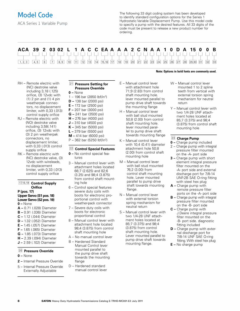
Model CodeACA Series 1 Variable Pump
The following 33 digit coding system has been developed to identify standard configuration options for the Series 1 Hydrostatic Variable Displacement Pump. Use this model code to specify a pump with the desired features. All 33 digits of the code must be present to release a new product number for ordering.
RH – Remote electric with (NC) destroke valve including 3,18 (.125) orifice, (3) 12vdc with (1) 2 pin and (1) 4 pin weatherpak connec-tors, no displacement limiter, with 0,33 (.013) control supply orifice
RJ – Remote electric with (NO) destroke valve including 3,58(.141) orifice, (3) 12vdc with (3) 2 pin weatherpak connectors, no displacement limiter, with 0,33 (.013) control supply orifice
RK – Remote electric with (NC) destroke valve, (3) 12vdc with wireleads, no displacement limiter, with 0,33 (.013) control supply orifice
17,18,19 Control Supply Orifice
P (pos. 17) Upper Servo (S1 pos. 18) Lower Servo (S2 pos. 19)0 – NoneA – 0.71 (.028) DiameterB – 0.91 (.036) DiameterC – 1.12 (.044) DiameterD – 1.32 (.052) DiameterE – 1.45 (.057) DiameterF – 1.65 (.065) DiameterG – 1.85 (.073) DiameterH – 2.39 (.094) DiameterJ – 2.59 (.102) Diameter
20 Pressure Override0 – None
2 – Internal Pressure Override
5 – Internal Pressure Override Externally Adjustable
21 Pressure Setting for Pressure Override
0 – None1 – 196 bar (2850 lbf/in2)D – 138 bar (2000 psi)E – 172 bar (2500 psi)F – 207 bar (3000 psi)G – 241 bar (3500 psi)H – 276 bar (4000 psi)J – 310 bar (4500 psi)K – 345 bar (5000 psi)L – 379 bar (5500 psi)M – 414 bar (6000 psi)P – 362 bar (5250 lbf/in2)
22 Control Special Features0 – No control special fea-
tures
3 – Manual control lever with attachment holes located 66;7 (2.625) and 82;6 (3.25) and 98;4 (3.875) from control shaft mount-ing hole
6 – Control special features severe duty coils with boots for electronic pro-portional control with weather-pack connector
7 – Severe duty coils with boots for electronic proportional control
8 – Manual control lever with attachment hole located 98;4 (3.875) from control shaft mounting hole
A – No manual control leverB – Hardened Standard
Manual Control lever mounted parallel to the pump drive shaft towards the mounting flange
D – Hardened standard manual control lever
E – Manual control lever with attachment hole 71;9 (2.83) from control shaft mounting hole. lever mounted parallel to pump drive shaft towards the mounting flange
H – Manual control lever with ball stud mounted 50;8 (2.00) from control shaft mounting hole. lever mounted paral-lel to pump drive shaft towards mounting flange
K – Manual control lever with 10;4 (0.41) diameter attachment hole 50;8 (2.00) from control shaft mounting hole
M – Manual control lever with ball stud mounted 76;2 (3.00) from control shaft mounting hole. Lever mounted parallel to pump drive shaft towards mounting flange.
N – Manual control lever with external torsion spring mechanism for neutral return
S – Manual control lever with two 1/4-28 UNF attach-ment holes located at 85;7 (3.375) and 98;4 (3.875) from control shaft mounting hole. Lever mounted parallel to pump drive shaft towards mounting flange.
W – Manual control lever mounted 1 to 2 spline teeth from vertical with external torsion spring mechanism for neutral return
Y – Manual control lever with two 1/4-28 UNF attach-ment holes located at 85;7 (3.375) and 98;4 (3.875) from control shaft mounting hole
23 Charge Pump0 – Charge pump included2 – Charge pump with integral
pressure filter mounted on the -A- port side
3 – Charge pump with short element integral pressure filter mounted on the -A- port side and external discharge port for 7/8-14 UNF-2B SAE O-ring fitting with steel hex plug
A – Charge pump with remote pressure filter ports on the -A- port side
B – Charge pump with integral pressure filter mounted on the -B- port side
C – Charge pump with J.Deere integral pressure filter mounted on the -B- port side. diagnostic fitting included
D – Charge pump with exter-nal discharge port for 7/8-14 UNF SAE O-ring fitting. With steel hex plug
E – No charge pump
Note: Options in bold fonts are commonly used.
eaton Heavy Duty Hydrostatic Transmissions Catalog E-TRHD-MC001-E2 July 2011 9
ACA 39 2 03 02 L 1 A C C EA A A A 2 C N A A 1 0 D A 15 0 0 B
6 7 12 19 332411 18 3210 17 3113 20 2514 21 2622 2723 281, 2, 3 4, 5 8, 9 15, 16 29,30
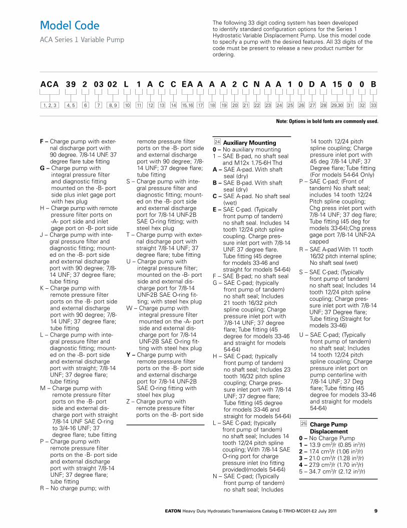
Model CodeACA Series 1 Variable Pump
The following 33 digit coding system has been developed to identify standard configuration options for the Series 1 Hydrostatic Variable Displacement Pump. Use this model code to specify a pump with the desired features. All 33 digits of the code must be present to release a new product number for ordering.
F – Charge pump with exter-nal discharge port with 90 degree. 7/8-14 UNF. 37 degree flare tube fitting
G – Charge pump with integral pressure filter and diagnostic fitting mounted on the -B- port side plus inlet gage port with hex plug
H – Charge pump with remote pressure filter ports on -A- port side and inlet gage port on -B- port side
J – Charge pump with inte-gral pressure filter and diagnostic fitting; mount-ed on the -B- port side and external discharge port with 90 degree; 7/8-14 UNF; 37 degree flare; tube fitting
K – Charge pump with remote pressure filter ports on the -B- port side and external discharge port with 90 degree; 7/8-14 UNF; 37 degree flare; tube fitting
L – Charge pump with inte-gral pressure filter and diagnostic fitting; mount-ed on the -B- port side and external discharge port with straight; 7/8-14 UNF; 37 degree flare; tube fitting
M – Charge pump with remote pressure filter ports on the -B- port side and external dis-charge port with straight 7/8-14 UNF SAE O-ring to 3/4-16 UNF; 37 degree flare; tube fitting
P – Charge pump with remote pressure filter ports on the -B- port side and external discharge port with straight 7/8-14 UNF; 37 degree flare; tube fitting
R – No charge pump; with
remote pressure filter ports on the -B- port side and external discharge port with 90 degree; 7/8-14 UNF; 37 degree flare; tube fitting
S – Charge pump with inte-gral pressure filter and diagnostic fitting; mount-ed on the -B- port side and external discharge port for 7/8-14 UNF-2B SAE O-ring fitting; with steel hex plug
T – Charge pump with exter-nal discharge port with straight 7/8-14 UNF; 37 degree flare; tube fitting
U – Charge pump with integral pressure filter; mounted on the -B- port side and external dis-charge port for 7/8-14 UNF-2B SAE O-ring fit-ting; with steel hex plug
W – Charge pump with integral pressure filter mounted on the -A- port side and external dis-charge port for 7/8-14 UNF-2B SAE O-ring fit-ting with steel hex plug
Y – Charge pump with remote pressure filter ports on the -B- port side and external discharge port for 7/8-14 UNF-2B SAE O-ring fitting with steel hex plug
Z – Charge pump with remote pressure filter ports on the -B- port side
24 Auxiliary Mounting0 – No auxiliary mounting1 – SAE B-pad, no shaft seal
and M12x 1.75-6H ThdA – SAE A-pad. With shaft
seal (dry)B – SAE B-pad. With shaft
seal (dry)C – SAE A-pad. No shaft seal
(wet)E – SAE C-pad. (Typically
front pump of tandem) no shaft seal. Includes 14 tooth 12/24 pitch spline coupling. Charge pres-sure inlet port with 7/8-14 UNF. 37 degree flare. Tube fitting (45 degree for models 33-46 and straight for models 54-64)
F – SAE B-pad; no shaft sealG – SAE C-pad; (typically
front pump of tandem) no shaft seal; Includes 21 tooth 16/32 pitch spline coupling; Charge pressure inlet port with 7/8-14 UNF; 37 degree flare; Tube fitting (45 degree for models 33-46 and straight for models 54-64)
H – SAE C-pad; (typically front pump of tandem) no shaft seal; Includes 23 tooth 16/32 pitch spline coupling; Charge pres-sure inlet port with 7/8-14 UNF; 37 degree flare; Tube fitting (45 degree for models 33-46 and straight for models 54-64)
L – SAE C-pad; (typically front pump of tandem) no shaft seal; Includes 14 tooth 12/24 pitch spline coupling; With 7/8-14 SAE O-ring port for charge pressure inlet (no fitting provided)(models 54-64)
N – SAE C-pad; (Typically front pump of tandem) no shaft seal; Includes
14 tooth 12/24 pitch spline coupling; Charge pressure inlet port with 45 deg 7/8-14 UNF; 37 Degree flare; Tube fitting (For models 54-64 Only)
P – SAE C-pad; (Front of tandem) No shaft seal; includes 14 tooth 12/24 Pitch spline coupling; Chg press inlet port with 7/8-14 UNF; 37 deg flare; Tube fitting (45 deg for models 33-64);Chg press gage port 7/8-14 UNF-2A capped
R – SAE A-pad With 11 tooth 16/32 pitch internal spline; No shaft seal (wet)
S – SAE C-pad; (Typically front pump of tandem) no shaft seal; Includes 14 tooth 12/24 pitch spline coupling; Charge pres-sure inlet port with 7/8-14 UNF; 37 Degree flare; Tube fitting (Straight for models 33-46)
U – SAE C-pad; (Typically front pump of tandem) no shaft seal; Includes 14 tooth 12/24 pitch spline coupling; Charge pressure inlet port on pump centerline with 7/8-14 UNF; 37 Deg flare; Tube fitting (45 degree for models 33-46 and straight for models 54-64)
25 Charge Pump Displacement
0 – No Charge Pump1 – 13.9 cm3/r (0.85 in3/r)2 – 17.4 cm3/r (1.06 in3/r)3 – 21.0 cm3/r (1.28 in3/r)4 – 27.9 cm3/r (1.70 in3/r)5 – 34.7 cm3/r (2.12 in3/r)
Note: Options in bold fonts are commonly used.
eaton Heavy Duty Hydrostatic Transmissions Catalog E-TRHD-MC001-E2 July 2011 10
ACA 39 2 03 02 L 1 A C C EA A A A 2 C N A A 1 0 D A 15 0 0 B
6 7 12 19 332411 18 3210 17 3113 20 2514 21 2622 2723 281, 2, 3 4, 5 8, 9 15, 16 29,30
Model CodeACA Series 1 Variable Pump
The following 33 digit coding system has been developed to identify standard configuration options for the Series 1 Hydrostatic Variable Displacement Pump. Use this model code to specify a pump with the desired features. All 33 digits of the code must be present to release a new product number for ordering.
26 2nd Displacement of Dual Element
0 – No Dual Element
27 Charge Pressure Rel Valve Setting
0 – NoneD – 15 bar (220 psi) - StandardE – 16 bar (240 lbf/in2)F – 18 bar (260 lbf/in2)G – 19 bar (280 psi)H – 21 bar (300 lbf/in2)J – 22 bar (320 lbf/in2)K – 23 bar (340 psi)L – 24 bar (350 lbf/in2)M – 26 bar (380 lbf/in2)N – 28 bar (410 lbf/in2)
28 Charge Pump Special Features
0 – No charge pump special features
A – Steel core charge pump gasket
B – Steel core charge pump gasket and 90 degree inlet fitting; 1 5/8-12 UN threaded end for 37 degree flare tubing ((1.25) OD tubing; (1.25) ID hose)
J – Steel core charge pump gasket; needle bearing
M – Charge inlet manifold with charge relief valve
N – Steel core charge pump gasket and charge inlet mainifold with charge relief valve
P – Charge inlet manifold with external discharge port for 7/8-14 unf sae o-ring port and steel hex plug in inlet port
29,30 Special Pump Assembly Features
00 – No special features05 – Bottom servo piston
with 0.0 degree stop11 – Both servo sleeves have
1/2-20 UNF-2B thread and steel hex bolts
12 – Bottom servo sleeve has 7/8-14 UNF SAE O-ring port with hex steel plug
13 – Model 76 shaft seal and grade 8 bolts in mount-ing flange to pump housing (models 54-64)
14 – Special thick section end cover gasket
15 – Rear pump unit for tandem pump assembly (no shaft seal)
18 – Hi-Speed rotating group (model 76)
32 – Both servo sleeves have 7/8-14 UNF SAE O-Ring ports and steel hex plugs
39 – Bottom servo piston with externally adjust-able stop
40 – Both servo pistons with externally adjustable stops
53 – Model 76 shaft seal58 – 1350 Series end yoke
assembled to drive shaft (Pos 8,9 must be Code 40)
59 – 1310 Series end yoke assembled to drive shaft (Pos 8,9 must be Code 40)
67 – Metal case drain plug in both ports
79 – Rear pump unit for tandem pump assembly (no shaft seal), both servo pistons with externally adjustable stops
82 – Rear pump unit for tandem assembly (no shaft seal), top servo piston with externally adjustable stop
83 – Externally adjustable displacement stops set at 3.32 in3/rev (54.4cc/rev)
31 Paint and Packaging0 – Painted primer blue
(standard)A – Painted finish black
32 Identification on Unit0 – Standard
33 Design CodeA – AB – B
Note: Options in bold fonts are commonly used.
eaton Heavy Duty Hydrostatic Transmissions Catalog E-TRHD-MC001-E2 July 2011 11
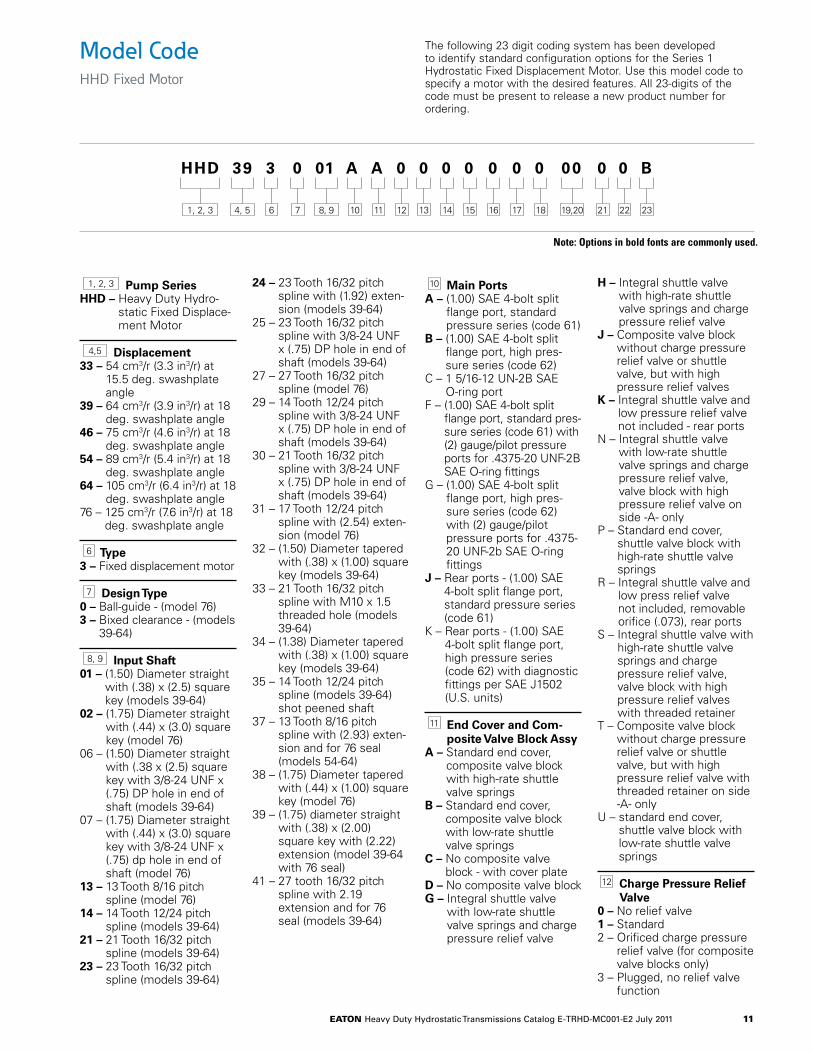
1, 2, 3 Pump SeriesHHD – Heavy Duty Hydro-
static Fixed Displace-ment Motor
4,5 Displacement 33 – 54 cm3/r (3.3 in3/r) at
15.5 deg. swashplate angle
39 – 64 cm3/r (3.9 in3/r) at 18 deg. swashplate angle
46 – 75 cm3/r (4.6 in3/r) at 18 deg. swashplate angle
54 – 89 cm3/r (5.4 in3/r) at 18 deg. swashplate angle
64 – 105 cm3/r (6.4 in3/r) at 18 deg. swashplate angle
76 – 125 cm3/r (7.6 in3/r) at 18 deg. swashplate angle
6 Type3 – Fixed displacement motor
7 Design Type0 – Ball-guide - (model 76)3 – Bixed clearance - (models
39-64)
8, 9 Input Shaft 01 – (1.50) Diameter straight
with (.38) x (2.5) square key (models 39-64)
02 – (1.75) Diameter straight with (.44) x (3.0) square key (model 76)
06 – (1.50) Diameter straight with (.38 x (2.5) square key with 3/8-24 UNF x (.75) DP hole in end of shaft (models 39-64)
07 – (1.75) Diameter straight with (.44) x (3.0) square key with 3/8-24 UNF x (.75) dp hole in end of shaft (model 76)
13 – 13 Tooth 8/16 pitch spline (model 76)
14 – 14 Tooth 12/24 pitch spline (models 39-64)
21 – 21 Tooth 16/32 pitch spline (models 39-64)
23 – 23 Tooth 16/32 pitch spline (models 39-64)
24 – 23 Tooth 16/32 pitch spline with (1.92) exten-sion (models 39-64)
25 – 23 Tooth 16/32 pitch spline with 3/8-24 UNF x (.75) DP hole in end of shaft (models 39-64)
27 – 27 Tooth 16/32 pitch spline (model 76)
29 – 14 Tooth 12/24 pitch spline with 3/8-24 UNF x (.75) DP hole in end of shaft (models 39-64)
30 – 21 Tooth 16/32 pitch spline with 3/8-24 UNF x (.75) DP hole in end of shaft (models 39-64)
31 – 17 Tooth 12/24 pitch spline with (2.54) exten-sion (model 76)
32 – (1.50) Diameter tapered with (.38) x (1.00) square key (models 39-64)
33 – 21 Tooth 16/32 pitch spline with M10 x 1.5 threaded hole (models 39-64)
34 – (1.38) Diameter tapered with (.38) x (1.00) square key (models 39-64)
35 – 14 Tooth 12/24 pitch spline (models 39-64) shot peened shaft
37 – 13 Tooth 8/16 pitch spline with (2.93) exten-sion and for 76 seal (models 54-64)
38 – (1.75) Diameter tapered with (.44) x (1.00) square key (model 76)
39 – (1.75) diameter straight with (.38) x (2.00) square key with (2.22) extension (model 39-64 with 76 seal)
41 – 27 tooth 16/32 pitch spline with 2.19 extension and for 76 seal (models 39-64)
10 Main PortsA – (1.00) SAE 4-bolt split
flange port, standard pressure series (code 61)
B – (1.00) SAE 4-bolt split flange port, high pres-sure series (code 62)
C – 1 5/16-12 UN-2B SAE O-ring port
F – (1.00) SAE 4-bolt split flange port, standard pres-sure series (code 61) with (2) gauge/pilot pressure ports for .4375-20 UNF-2B SAE O-ring fittings
G – (1.00) SAE 4-bolt split flange port, high pres-sure series (code 62) with (2) gauge/pilot pressure ports for .4375-20 UNF-2b SAE O-ring fittings
J – Rear ports - (1.00) SAE 4-bolt split flange port, standard pressure series (code 61)
K – Rear ports - (1.00) SAE 4-bolt split flange port, high pressure series (code 62) with diagnostic fittings per SAE J1502 (U.S. units)
11 End Cover and Com-posite Valve Block Assy
A – Standard end cover, composite valve block with high-rate shuttle valve springs
B – Standard end cover, composite valve block with low-rate shuttle valve springs
C – No composite valve block - with cover plate
D – No composite valve blockG – Integral shuttle valve
with low-rate shuttle valve springs and charge pressure relief valve
H – Integral shuttle valve with high-rate shuttle valve springs and charge pressure relief valve
J – Composite valve block without charge pressure relief valve or shuttle valve, but with high pressure relief valves
K – Integral shuttle valve and low pressure relief valve not included - rear ports
N – Integral shuttle valve with low-rate shuttle valve springs and charge pressure relief valve, valve block with high pressure relief valve on side -A- only
P – Standard end cover, shuttle valve block with high-rate shuttle valve springs
R – Integral shuttle valve and low press relief valve not included, removable orifice (.073), rear ports
S – Integral shuttle valve with high-rate shuttle valve springs and charge pressure relief valve, valve block with high pressure relief valves with threaded retainer
T – Composite valve block without charge pressure relief valve or shuttle valve, but with high pressure relief valve with threaded retainer on side -A- only
U – standard end cover, shuttle valve block with low-rate shuttle valve springs
12 Charge Pressure Relief Valve
0 – No relief valve1 – Standard2 – Orificed charge pressure
relief valve (for composite valve blocks only)
3 – Plugged, no relief valve function
HHD 39 3 0 01 A A 0 0 0 0 0 0 0 00 0 0 B
6 7 1211 1810 1713 1514 16 21 22 231, 2, 3 4, 5 8, 9 19,20
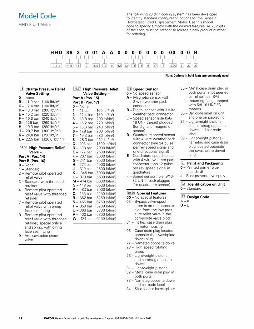
Model CodeHHD Fixed Motor
The following 23 digit coding system has been developed to identify standard configuration options for the Series 1 Hydrostatic Fixed Displacement Motor. Use this model code to specify a motor with the desired features. All 23-digits of the code must be present to release a new product number for ordering.
Note: Options in bold fonts are commonly used.
eaton Heavy Duty Hydrostatic Transmissions Catalog E-TRHD-MC001-E2 July 2011 12
13 Charge Pressure Relief Valve Setting
0 – noneB – 11,0 bar (160 lbf/in2)C – 12,4 bar (180 lbf/in2)D – 13,8 bar (200 lbf/in2)E – 15,2 bar (220 lbf/in2)F – 16,6 bar (240 lbf/in2)G – 17,9 bar (260 lbf/in2)H – 19,3 bar (280 lbf/in2)J – 20,7 bar (300 lbf/in2)K – 24,0 bar (350 lbf/in2)L – 22,5 bar (326.6 lbf/in2)
14, 16 High Pressure Relief Valve –
Port A (Pos. 14) Port B (Pos. 16)0 – None1 – Standard2 – Remote pilot operated
relief valve3 – Standard with threaded
retainer4 – Remote pilot operated
relief valve with threaded retainer
7 – Remote pilot operated relief valve with o-ring face seal fitting
8 – Remote pilot operated relief valve with threaded retainer, special orifice and spring, with o-ring face seal fitting
9 – Anti-cavitation check valve
15, 17 High Pressure Relief Valve Setting –
Port A (Pos. 15) Port B (Pos. 17)0 – None1 – 11 bar (160 lbf/in2)2 – 12,4 bar (180 lbf/in2)3 – 13,8 bar (200 lbf/in2)4 – 15,2 bar (220 lbf/in2)5 – 16,6 bar (240 lbf/in2)6 – 17,9 bar (260 lbf/in2)7 – 19,3 bar (280 lbf/in2)8 – 28,3 bar (410 lbf/in2)C – 103 bar (1500 lbf/in2)D – 138 bar (2000 lbf/in2)E – 172 bar (2500 lbf/in2)F – 207 bar (3000 lbf/in2)G – 241 bar (3500 lbf/in2)H – 276 bar (4000 lbf/in2)J – 310 bar (4500 lbf/in2)K – 345 bar (5000 lbf/in2)L – 379 bar (5500 lbf/in2)M – 414 bar (6000 lbf/in2)N – 448 bar (6500 lbf/in2)P – 483 bar (7000 lbf/in2)Q – 155 bar (2250 lbf/in2)R – 362 bar (5250 lbf/in2)S – 466 bar (6750 lbf/in2)T – 359 bar (5200 lbf/in2)U – 366 bar (5300 lbf/in2)V – 400 bar (5800 lbf/in2)W – 431 bar (6250 lbf/in2)
18 Speed Sensor0 – No speed sensorA – Magnetic sensor with
2 wire weather pack connector
B – Digital sensor with 3 wire weather pack connector
C – Speed sensor hole (5/8-18 UNF thread) plugged (for digital or magnetic sensor)
D – Quadrature speed sensor with 4 wire weather pack connector (one 24 pulse per rev speed signal and one directional signal)
E – Quadrature speed sensor with 4 wire weather pack connector (two 12 pulse per rev speed signal in quadrature)
F – Speed sensor hole (9/16-32 UN thread) plugged (for quadrature sensor)
19,20 Special Features 00 – No special features03 – Bypass valve-spool
stem is on the opposite side from the low pres-sure relief valve in the composite valve block
04 – Int hex case drain plug in motor housing
05 – Case drain plug located opposite the swashplate dowel plug
22 – Nametag opposite dowel23 – High speed rotating
group26 – Lightweight pistons
and nametag opposite dowel
31 – Lightweight pistons32 – Metal case drain plug in
both ports33 – Nametag opposite dowel
and bar code label34 – Shot peened barrel splines
35 – Metal case drain plug in both ports, shot peened barrel splines, SAE mounting flange tapped with 5/8-18 UNF-2B threads
36 – Bar code label on unit and one on packaging
37 – Lightweight pistons and nametag opposite dowel and bar code label
39 – Lightweight pistons - nametag and case drain plug located opposite the swashplate dowel plug
21 Paint and Packaging0 – Painted primer blue
(standard)J – Rust preventative spray
22 Identification on Unit0 – Standard
23 Design CodeA – AB – B
HHD 39 3 0 01 A A 0 0 0 0 0 0 0 00 0 0 B
6 7 1211 1810 1713 1514 16 21 22 231, 2 ,3 4, 5 8, 9 19,20
Model CodeHHD Fixed Motor
The following 23 digit coding system has been developed to identify standard configuration options for the Series 1 Hydrostatic Fixed Displacement Motor. Use this model code to specify a motor with the desired features. All 23-digits of the code must be present to release a new product number for ordering.
Note: Options in bold fonts are commonly used.
eaton Heavy Duty Hydrostatic Transmissions Catalog E-TRHD-MC001-E2 July 2011 13
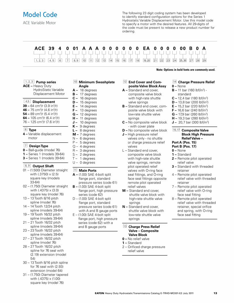
1, 2, 3 Pump seriesACE – Heavy Duty
HydroStatic Variable Displacement Motor
4,5 Displacement 39 – 64 cm3/r (3.9 in3/r) 46 – 75 cm3/r (4.6 in3/r) 54 – 89 cm3/r (5.4 in3/r) 64 – 105 cm3/r (6.4 in3/r) 76 – 125 cm3/r (7.6 in3/r)
6 Type4 – Variable displacement
motor
7 Design Type0 – Ball-guide (model 76)1 – Series 1 (models 39-64)3 – Series 1 (models 39-64)
8, 9 Output Shaft 01 – (1.500) Diameter straight
with (.3750) x (2.5) square key (models 33-64)
02 – (1.750) Diameter straight with (.4375) x (3.0) square key (model 76)
13 – 13 Tooth 8/16 pitch spline (model 76)
14 – 14 Tooth 12/24 pitch spline (models 39-64)
19 – 19 Tooth 16/32 pitch spline (models 39-64)
21 – 21 Tooth 16/32 pitch spline (models 39-64)
23 – 23 Tooth 16/32 pitch spline (models 39-64)
27 – 27 Tooth 16/32 pitch spline (model 76)
28 – 27 Tooth 16/32 pitch spline for 76 seal with (2.19) extension (model 54)
30 – 13 Tooth 8/16 pitch spline for 76 seal with (2.93) extension (model 64)
31 – (1.750) Diameter tapered with (.4375) x (1.00) square key (model 76)
10 Minimum Swashplate Angle
A – 18 degreesB – 17 degreesC – 16 degreesD – 15 degreesE – 14 degreesF – 13 degreesG – 12 degreesH – 11 degreesJ – 10 degreesK – 9 degreesL – 8 degreesM – 7 degreesN – 6 degreesP – 5 degreesQ – 4 degreesR – 3 degreesS – 2 degreesT – 1 degreesU – 0 degrees
11 Main PortsA – (1.00) SAE 4-bolt split
flange port, standard pressure series (code 61)
B – (1.00) SAE 4-bolt split flange port, high pressure series (code 62)
D – (1.00) SAE 4-bolt split flange port, standard pressure series (code 61) with A and B gauge ports
E – (1.00) SAE 4-bolt split flange port, high pressure series (code 62) with a and B gauge ports
12 End Cover and Com-posite Valve Block Assy
A – Standard end cover, composite valve block with high-rate shuttle valve springs
B – Standard end cover, com-posite valve block with low-rate shuttle valve springs
C – No composite valve block - with cover plate
D – No composite valve blockJ – High pressure relief
valves only - no shuttle or charge pressure relief valves
L – Standard end cover, composite valve block with high-rate shuttle valve springs, remote pilot operated relief valves with O-ring face seal fittings, and O-ring face seal fittings opposite remote pilot operated relief valves
M – Standard end cover, shuttle valve block with high-rate shuttle valve springs
N – Standard end cover, shuttle valve block with low-rate shuttle valve springs
13 Charge Press Relief Valve – Composite Valve Block
0 – No relief valve1 – Standard2 – Orificed charge pressure
relief valve
14 Charge Pressure Relief0 – NoneB – 11 bar (160 lbf/in2) -
standardC – 12,4 bar (180 lbf/in2)D – 13,8 bar (200 lbf/in2)E – 15,2 bar (220 lbf/in2)F – 16,6 bar (240 lbf/in2)G – 17,9 bar (260 lbf/in2)H – 19,3 bar (280 lbf/in2)J – 20,7 bar (300 lbf/in2)
15, 17 Composite Valve Block High Pressure Relief Valve –
Port A (Pos. 15) Port B (Pos. 17)0 – None1 – Standard2 – Remote pilot operated
relief valve3 – Standard with threaded
retainer4 – Remote pilot operated
relief valve with threaded retainer
7 – Remote pilot operated relief valve with O-ring face seal fitting
8 – Remote pilot operated relief valve with threaded retainer, special orifice and spring, with O-ring face seal fitting
ACE 39 4 0 01 A A A 0 0 0 0 0 0 EA 0 0 0 0 00 B 0 A
6 7 1211 1810 1713 1514 16 21 22 2723 2824 291, 2, 3 4, 5 8, 9 19, 20 25, 26
Model CodeACE Variable Motor
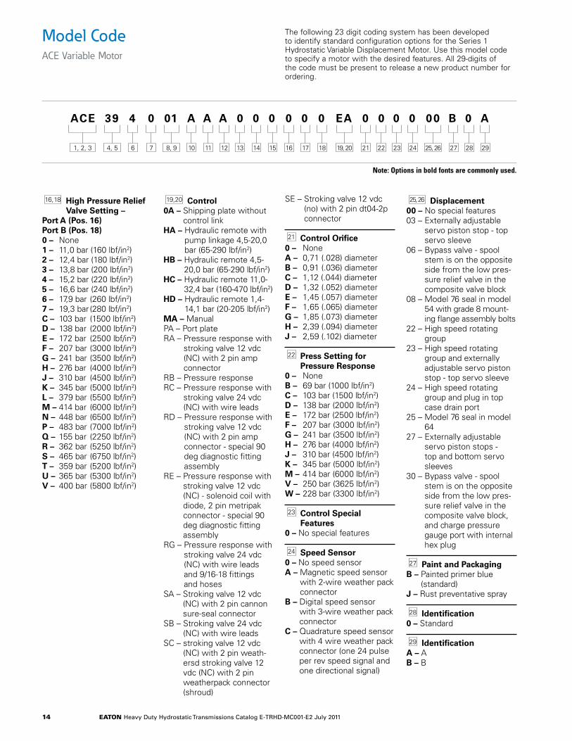
The following 23 digit coding system has been developed to identify standard configuration options for the Series 1 Hydrostatic Variable Displacement Motor. Use this model code to specify a motor with the desired features. All 29-digits of the code must be present to release a new product number for ordering.
Note: Options in bold fonts are commonly used.
eaton Heavy Duty Hydrostatic Transmissions Catalog E-TRHD-MC001-E2 July 2011 14
16, 18 High Pressure Relief Valve Setting –
Port A (Pos. 16) Port B (Pos. 18)0 – None1 – 11,0 bar (160 lbf/in2)2 – 12,4 bar (180 lbf/in2)3 – 13,8 bar (200 lbf/in2)4 – 15,2 bar (220 lbf/in2)5 – 16,6 bar (240 lbf/in2)6 – 17,9 bar (260 lbf/in2)7 – 19,3 bar (280 lbf/in2)C – 103 bar (1500 lbf/in2)D – 138 bar (2000 lbf/in2)E – 172 bar (2500 lbf/in2)F – 207 bar (3000 lbf/in2)G – 241 bar (3500 lbf/in2)H – 276 bar (4000 lbf/in2)J – 310 bar (4500 lbf/in2)K – 345 bar (5000 lbf/in2)L – 379 bar (5500 lbf/in2)M – 414 bar (6000 lbf/in2)N – 448 bar (6500 lbf/in2)P – 483 bar (7000 lbf/in2)Q – 155 bar (2250 lbf/in2)R – 362 bar (5250 lbf/in2)S – 465 bar (6750 lbf/in2)T – 359 bar (5200 lbf/in2)U – 365 bar (5300 lbf/in2)V – 400 bar (5800 lbf/in2)
19,20 Control0A – Shipping plate without
control linkHA – Hydraulic remote with
pump linkage 4,5-20,0 bar (65-290 lbf/in2)
HB – Hydraulic remote 4,5-20,0 bar (65-290 lbf/in2)
HC – Hydraulic remote 11,0-32,4 bar (160-470 lbf/in2)
HD – Hydraulic remote 1,4-14,1 bar (20-205 lbf/in2)
MA – ManualPA – Port plateRA – Pressure response with
stroking valve 12 vdc (NC) with 2 pin amp connector
RB – Pressure responseRC – Pressure response with
stroking valve 24 vdc (NC) with wire leads
RD – Pressure response with stroking valve 12 vdc (NC) with 2 pin amp connector - special 90 deg diagnostic fitting assembly
RE – Pressure response with stroking valve 12 vdc (NC) - solenoid coil with diode, 2 pin metripak connector - special 90 deg diagnostic fitting assembly
RG – Pressure response with stroking valve 24 vdc (NC) with wire leads and 9/16-18 fittings and hoses
SA – Stroking valve 12 vdc (NC) with 2 pin cannon sure-seal connector
SB – Stroking valve 24 vdc (NC) with wire leads
SC – stroking valve 12 vdc (NC) with 2 pin weath-ersd stroking valve 12 vdc (NC) with 2 pin weatherpack connector (shroud)
SE – Stroking valve 12 vdc (no) with 2 pin dt04-2p connector
21 Control Orifice0 – NoneA – 0,71 (.028) diameterB – 0,91 (.036) diameterC – 1,12 (.044) diameterD – 1,32 (.052) diameterE – 1,45 (.057) diameterF – 1,65 (.065) diameterG – 1,85 (.073) diameterH – 2,39 (.094) diameterJ – 2,59 (.102) diameter
22 Press Setting for Pressure Response
0 – NoneB – 69 bar (1000 lbf/in2)C – 103 bar (1500 lbf/in2)D – 138 bar (2000 lbf/in2)E – 172 bar (2500 lbf/in2)F – 207 bar (3000 lbf/in2)G – 241 bar (3500 lbf/in2)H – 276 bar (4000 lbf/in2)J – 310 bar (4500 lbf/in2)K – 345 bar (5000 lbf/in2)M – 414 bar (6000 lbf/in2)V – 250 bar (3625 lbf/in2)W – 228 bar (3300 lbf/in2)
23 Control Special Features
0 – No special features
24 Speed Sensor0 – No speed sensorA – Magnetic speed sensor
with 2-wire weather pack connector
B – Digital speed sensor with 3-wire weather pack connector
C – Quadrature speed sensor with 4 wire weather pack connector (one 24 pulse per rev speed signal and one directional signal)
25, 26 Displacement 00 – No special features03 – Externally adjustable
servo piston stop - top servo sleeve
06 – Bypass valve - spool stem is on the opposite side from the low pres-sure relief valve in the composite valve block
08 – Model 76 seal in model 54 with grade 8 mount-ing flange assembly bolts
22 – High speed rotating group
23 – High speed rotating group and externally adjustable servo piston stop - top servo sleeve
24 – High speed rotating group and plug in top case drain port
25 – Model 76 seal in model 64
27 – Externally adjustable servo piston stops - top and bottom servo sleeves
30 – Bypass valve - spool stem is on the opposite side from the low pres-sure relief valve in the composite valve block, and charge pressure gauge port with internal hex plug
27 Paint and PackagingB – Painted primer blue
(standard)J – Rust preventative spray
28 Identification0 – Standard
29 IdentificationA – AB – B
ACE 39 4 0 01 A A A 0 0 0 0 0 0 EA 0 0 0 0 00 B 0 A
6 7 1211 1810 1713 1514 16 21 22 2723 2824 291, 2, 3 4, 5 8, 9 19, 20 25, 26
Model CodeACE Variable Motor
The following 23 digit coding system has been developed to identify standard configuration options for the Series 1 Hydrostatic Variable Displacement Motor. Use this model code to specify a motor with the desired features. All 29-digits of the code must be present to release a new product number for ordering.
Note: Options in bold fonts are commonly used.
eaton Heavy Duty Hydrostatic Transmissions Catalog E-TRHD-MC001-E2 July 2011 15
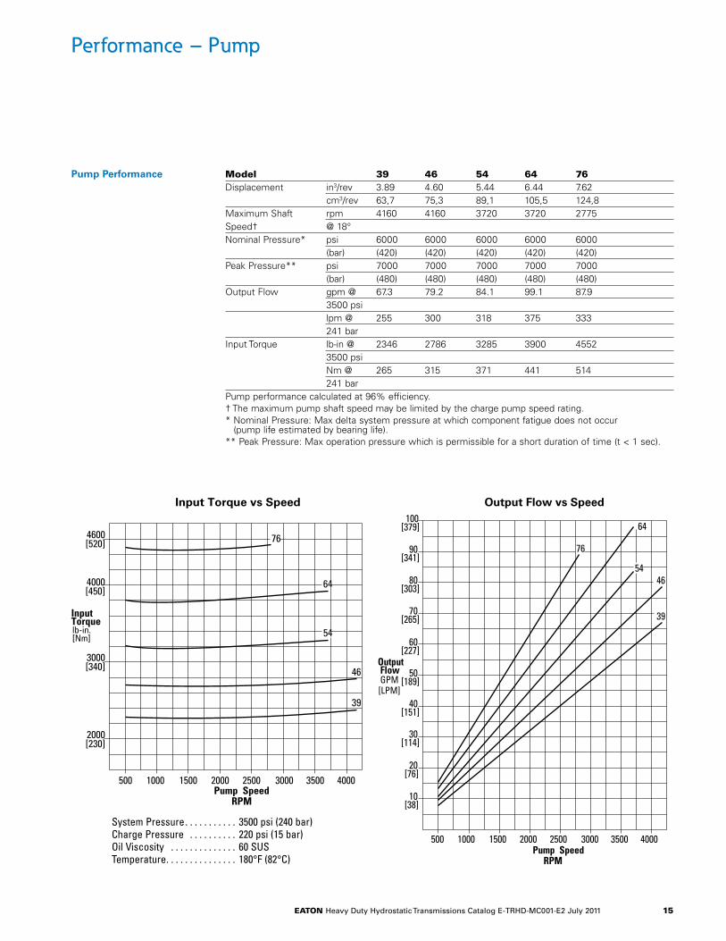
Performance – Pump
2000[230]
3000[340]
4000[450]
4600[520] 76
39
46
54
64
Pump SpeedRPM
Input
Input Torque vs Speed Output Flow vs Speed
Torquelb-in.[Nm]
500 1000 1500 2000 2500 3000 3500 4000
500 1000 1500 2000 2500 3000 3500 4000
76
54
64
10[38]
20[76]
30[114]
40[151]
50[189]
60[227]
70[265]
80[303]
90[341]
100[379]
39
46
Pump SpeedRPM
OutputFlowGPM[LPM]
Pump Performance Model 39 46 54 64 76Displacement in3/rev 3.89 4.60 5.44 6.44 7.62 cm3/rev 63,7 75,3 89,1 105,5 124,8Maximum Shaft rpm 4160 4160 3720 3720 2775Speed† @ 18°Nominal Pressure* psi 6000 6000 6000 6000 6000 (bar) (420) (420) (420) (420) (420)Peak Pressure** psi 7000 7000 7000 7000 7000 (bar) (480) (480) (480) (480) (480)Output Flow gpm @ 67.3 79.2 84.1 99.1 87.9 3500 psi lpm @ 255 300 318 375 333 241 barInput Torque lb-in @ 2346 2786 3285 3900 4552 3500 psi Nm @ 265 315 371 441 514 241 barPump performance calculated at 96% efficiency.† The maximum pump shaft speed may be limited by the charge pump speed rating.* Nominal Pressure: Max delta system pressure at which component fatigue does not occur
(pump life estimated by bearing life).** Peak Pressure: Max operation pressure which is permissible for a short duration of time (t < 1 sec).
System Pressure . . . . . . . . . . . 3500 psi (240 bar)Charge Pressure . . . . . . . . . . 220 psi (15 bar)Oil Viscosity . . . . . . . . . . . . . . 60 SUSTemperature . . . . . . . . . . . . . . . 180°F (82°C)
eaton Heavy Duty Hydrostatic Transmissions Catalog E-TRHD-MC001-E2 July 2011 16
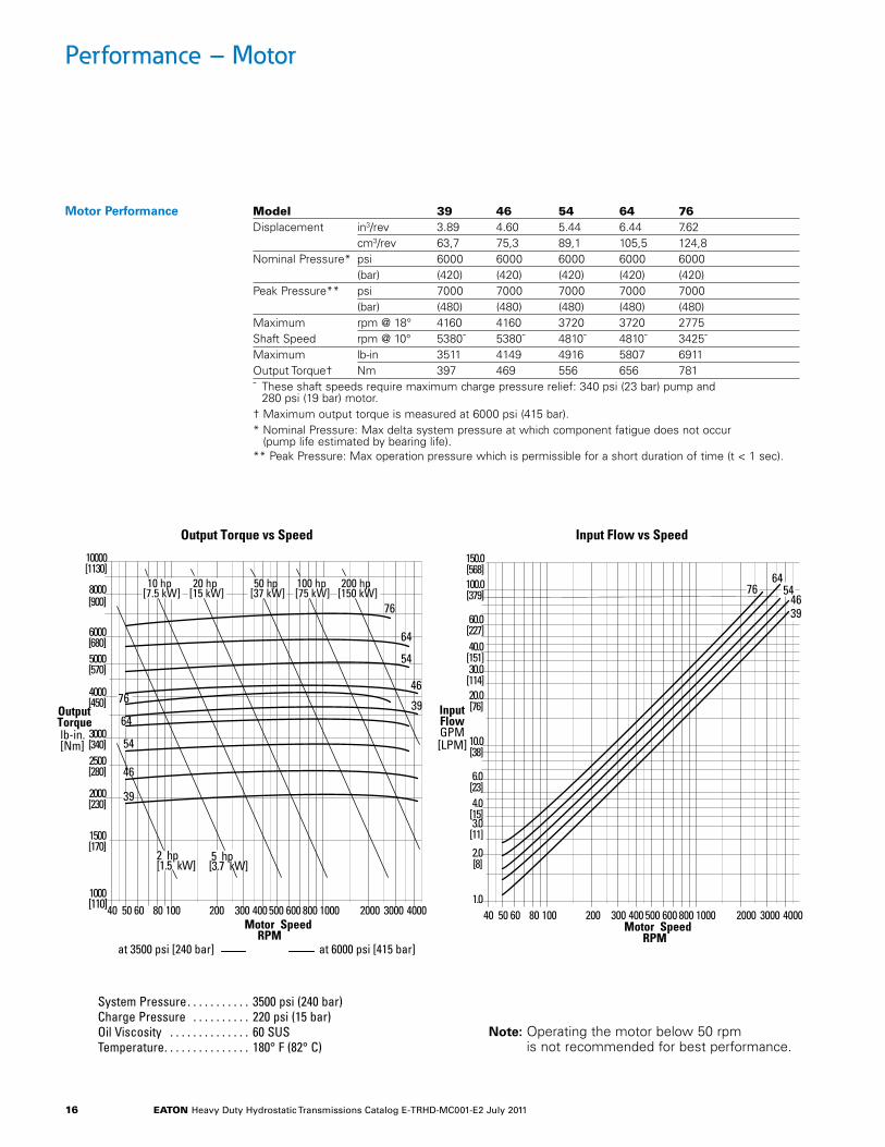
Performance – Motor
10080605040 1000800600500400300200 400030002000
10000[1130]
8000[900]
6000[680]5000[570]
4000[450]
3000[340]
2000[230]
1000[110]
1500[170]
2500[280]
Motor SpeedRPM
OutputTorquelb-in.[Nm]
50 hp[37 kW]
20 hp[15 kW]
10 hp[7.5 kW]
5 hp[3.7 kW]
2 hp[1.5 kW]
39
39
46
46
54
54
64
64
76
76
at 6000 psi [415 bar]at 3500 psi [240 bar]
200 hp[150 kW]
100 hp[75 kW]
Output Torque vs Speed Input Flow vs Speed
150.0[568]100.0[379]
60.0[227]40.0
[151]
20.0[76]
10.0[38]
6.0[23]4.0
[15]3.0
[11]
2.0[8]
1.0
Motor SpeedRPM
InputFlowGPM[LPM]
30.0[114]
3946
5464
76
10080605040 1000800600500400300200 400030002000
System Pressure . . . . . . . . . . . 3500 psi (240 bar)Charge Pressure . . . . . . . . . . 220 psi (15 bar)Oil Viscosity . . . . . . . . . . . . . . 60 SUSTemperature . . . . . . . . . . . . . . . 180° F (82° C)
Note: Operating the motor below 50 rpmis not recommended for best performance.
Model 39 46 54 64 76Displacement in3/rev 3.89 4.60 5.44 6.44 7.62 cm3/rev 63,7 75,3 89,1 105,5 124,8Nominal Pressure* psi 6000 6000 6000 6000 6000 (bar) (420) (420) (420) (420) (420) Peak Pressure** psi 7000 7000 7000 7000 7000 (bar) (480) (480) (480) (480) (480) Maximum rpm @ 18° 4160 4160 3720 3720 2775Shaft Speed rpm @ 10° 5380˜ 5380˜ 4810˜ 4810˜ 3425˜Maximum lb-in 3511 4149 4916 5807 6911Output Torque† Nm 397 469 556 656 781˜ These shaft speeds require maximum charge pressure relief: 340 psi (23 bar) pump and
280 psi (19 bar) motor.† Maximum output torque is measured at 6000 psi (415 bar).* Nominal Pressure: Max delta system pressure at which component fatigue does not occur
(pump life estimated by bearing life).** Peak Pressure: Max operation pressure which is permissible for a short duration of time (t < 1 sec).
Motor Performance
eaton Heavy Duty Hydrostatic Transmissions Catalog E-TRHD-MC001-E2 July 2011 17
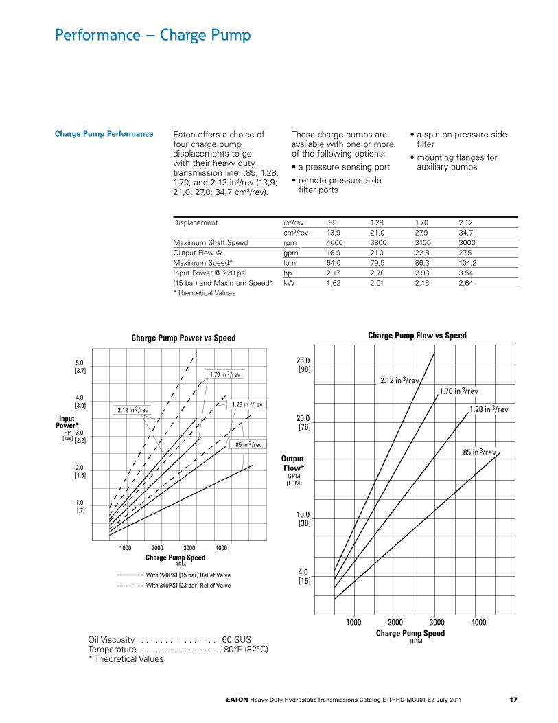
Performance – Charge Pump
Eaton offers a choice of four charge pump displacements to go with their heavy duty transmission line: .85, 1.28, 1.70, and 2.12 in3/rev (13,9; 21,0; 27,8; 34,7 cm3/rev).
These charge pumps are available with one or more of the following options:
• a pressure sensing port
• remote pressure side filter ports
• a spin-on pressure side filter
• mounting flanges for auxiliary pumps
1000 2000 3000 4000
20.0[76]
10.0[38]
OutputFlow*
GPM[LPM]
Charge Pump SpeedRPM
4.0[15]
26.0[98]
2.12 in 3/rev1.70 in 3/rev
1.28 in 3/rev
.85 in 3/rev
Charge Pump Flow vs SpeedCharge Pump Power vs Speed
1000 2000 3000 4000
5.0[3.7]
2.0[1.5]
InputPower*
HP[kW]
Charge Pump SpeedRPM
1.0[.7]
4.0[3.0]
3.0[2.2]
2.12 in 3/rev
1.70 in 3/rev
1.28 in 3/rev
.85 in 3/rev
With 220PSI [15 bar] Relief Valve
With 340PSI [23 bar] Relief Valve
Oil Viscosity . . . . . . . . . . . . . . . . 60 SUSTemperature . . . . . . . . . . . . . . . . 180°F (82°C)* Theoretical Values
Displacement in3/rev .85 1.28 1.70 2.12 cm3/rev 13,9 21,0 27,9 34,7Maximum Shaft Speed rpm 4600 3800 3100 3000Output Flow @ gpm 16.9 21.0 22.8 27.5Maximum Speed* lpm 64,0 79,5 86,3 104,2Input Power @ 220 psi hp 2.17 2.70 2.93 3.54(15 bar) and Maximum Speed* kW 1,62 2,01 2,18 2,64*Theoretical Values
Charge Pump Performance
eaton Heavy Duty Hydrostatic Transmissions Catalog E-TRHD-MC001-E2 July 2011 18
75,5(2.97)
90,8(3.58)
38,1(1.50)
20,3(.80)
66,6(2.62)
247,0(9.72)
NeutralAdjustment
Control Valve
1
2
Mounting Surface
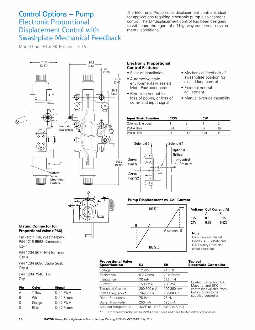
The Electronic Proportional displacement control is ideal for applications requiring electronic pump displacement control. The EP displacement control has been designed to withstand the rigors of off-highway equipment environ-mental conditions.
Control Options – PumpElectronic Proportional Displacement Control with Swashplate Mechanical FeedbackModel Code EJ & EK Position 15,16
• Ease of installation
• Automotive style environmentally sealed Metri-Pack connectors
• Return to neutral for loss of power, or loss of command input signal
• Mechanical feedback of swashplate position for closed loop control
• External neutral adjustment
• Manual override capability
Electronic Proportional Control Features
Pump Displacement vs. Coil Current
Solenoid 2
Servo Port S1
Servo Port S2
Control Pressure
Optional Orifice
Solenoid 1
A Current (A) B-B -A
100%
100%
Voltage Coil Current (A) A B12V 0.5 1.2524V 0.25 0.625
Mating Connector for Proportional Valve (IP66)
Packard 4 Pin, Weatherpack P/N 1218 6568 Connector, Qty 1
P/N 1204 8074 PIN Terminal, Qty 4
P/N 1204 8086 Cable Seal, Qty 4
P/N 1204 7948 TPA, Qty 1
Input Shaft Rotation CCW CW
Solenoid Energized 1 2 1 2Port A Flow Out In In OutPort B Flow In Out Out In
Proportional Valve typical Specification eJ eK electronic Controller
Voltage 12 VDC 24 VDC Resistance 5.2 Ohms 20.8 OhmsInductance 7.0 mH 27.7 mHCurrent 1500 mA 750 mAThreshold Current 200-600 mA 100-300 mAPWM Frequency* 70-200 Hz 70-200 HzDither Frequency 75 Hz 75 HzDither Amplitude 250 mA 125 mAAmbient Temperature -65°F to 140°F (-54°C to 60°C)
* 100 Hz recommended when PWM driver does not have built-in dither capabilities
Contact Eaton for TCA, Maestro, and EFX controller available from Eaton; or customer supplied controller.
Pin Color Signal
A Yellow Coil 1 PWMB White Coil 1 ReturnC Orange Coil 2 PWMD Black Coil 2 Return
Note: Coils have no internal Diodes. A-B Polarity and C-D Polarity Does Not affect operation
eaton Heavy Duty Hydrostatic Transmissions Catalog E-TRHD-MC001-E2 July 2011 19
Note: Coils have no internal Diodes. A-B Polarity and C-D Polarity Does Not affect operation
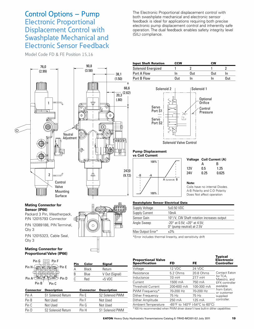
Input Shaft Rotation CCW CW
Solenoid Energized 1 2 1 2Port A Flow In Out Out InPort B Flow Out In In Out
Connector Description Connector Description
Pin A S1 Solenoid Return Pin E S2 Solenoid PWMPin B Not Used Pin F Not UsedPin C Not Used Pin G Not UsedPin D S2 Solenoid Return Pin H S1 Solenoid PWM
The Electronic Proportional displacement control with both swashplate mechanical and electronic sensor feedback is ideal for applications requiring both precise electronic pump displacement control and inherently safe operation. The dual feedback enables safety integrity level (SIL) compliance.
Control Options – PumpElectronic Proportional Displacement Control with Swashplate Mechanical and Electronic Sensor FeedbackModel Code FD & FE Position 15,16
typical Proportional Valve electronic Specification FD Fe Controller
Voltage 12 VDC 24 VDC Resistance 5.2 Ohms 20.8 OhmsInductance 7.0 mH 27.7 mHCurrent 1500 mA 750 mAThreshold Current 200-600 mA 100-300 mAPWM Frequency* 70-200 Hz 70-200 HzDither Frequency 75 Hz 75 HzDither Amplitude 250 mA 125 mAAmbient Temperature -65°F to 140°F (-54°C to 60°C)*100 Hz recommended when PWM driver doesn’t have built-in dither capabilities
Pin G
Pin B
Pin F
Pin C
Pin H Pin E
Pin A Pin D
76,0(2.99)
90,8(3.58)
38,1(1.50)
20,3(.80)
66,6(2.62)
247,0(9.72)
NeutralAdjustment
1
2
Control ValveMounting Surface
Contact Eaton for TCA, Maestro, and EFX controller available from Eaton; or customer supplied controller.
Mating Connector for Sensor (IP66)Packard 3 Pin, Weatherpack, P/N 12015793 Connector
P/N 12089188, PIN Terminal, Qty 3
P/N 12015323, Cable Seal, Qty 3
Mating Connector for Proportional Valve (IP66)
Solenoid 2
Servo Port S1
Servo Port S2
Solenoid Valve Control
Solenoid 1
Optional OrificeControl Pressure
A Current (A) B-B -A
100%
100%
Pin Color Signal
A Black ReturnB Blue V Out (Signal)C Red +5 VDC
Swatchplate Sensor electrical Data
Supply Voltage 5±0.50 VDCSupply Current 10mASensor Gain 10°/V, CW Shaft rotation increases outputAngle Sweep -20° at 0.5V; +20° at 4.5V;
0° (pump neutral) at 2.5VMax Output Error* ±3% *Error includes thermal linearity, and sensitivity drift
Voltage Coil Current (A)A B
12V 0 .5 1 .2524V 0 .25 0 .625
Pump Displacement vs Coil Current
eaton Heavy Duty Hydrostatic Transmissions Catalog E-TRHD-MC001-E2 July 2011 20
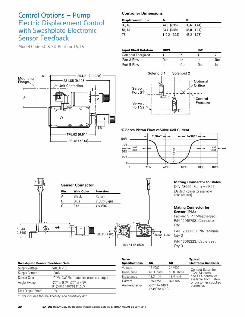
Control Options – Pump Electric Displacement Control with Swashplate Electronic Sensor FeedbackModel Code SC & SD Position 15,16
Mating Connector for Valve DIN 43650, Form A (IP65)(Deutsch connector available upon request)
Mating Connector for Sensor (IP66) Packard 3 Pin Weatherpack P/N 12015793, Connector Qty 1
P/N 12089188, PIN Terminal, Qty 3
P/N 12015323, Cable Seal, Qty 3
Input Shaft Rotation CCW CW
Solenoid Energized 1 2 1 2Port A Flow Out In In OutPort B Flow In Out Out In
AMounting Flange
254,71 (10.028)
B
Unit Centerline231,85 (9.128)
175,62 (6.914)
198,48 (7.814)
59,44(2.340)
143,51 (5.650)
29,21 (1.150) 26,92 (1.060)
2
1
Solenoid 1
Servo Port S1
Servo Port S2
Optional Orifice
ControlPressure
Solenoid 2
AMounting Flange
254,71 (10.028)
B
Unit Centerline231,85 (9.128)
175,62 (6.914)
198,48 (7.814)
59,44(2.340)
143,51 (5.650)
29,21 (1.150) 26,92 (1.060)
2
1
Solenoid 1
Servo Port S1
Servo Port S2
Optional Orifice
ControlPressure
Solenoid 2
Valve typical Specifications SC SD electronic Controller
Voltage 12 VDC 24 VDC Resistance 4.0 Ohms 16.0 OhmsInductance 12.3 mH 49.4 mHCurrent 1750 mA 875 mAAmbient Temp -65°F to 140°F (-54°C to 60°C)
Contact Eaton for TCA, Maestro, and EFX controller available from Eaton; or customer supplied controller.
Solenoid 1
Servo Port S1
Servo Port S2
Optional Orifice
ControlPressure
Solenoid 2
Displacement in3/r a B
39, 46 74,9 (2 .95) 36,6 (1 .44)54, 64 93,7 (3 .69) 45,0 (1 .77)76 110,2 (4 .34) 45,2 (1 .78)
Pin Wire Color Function
A Black ReturnB Blue V Out (Signal)C Red + 5 VDC
Sensor Connector
% Servo Piston Flow vs Valve Coil Current
Swashplate Sensor electrical Data
Supply Voltage 5±0.50 VDCSupply Current 10mASensor Gain 10°/V, CW Shaft rotation increases outputAngle Sweep -20° at 0.5V; +20° at 4.5V;
0° (pump neutral) at 2.5VMax Output Error* ±3% *Error includes thermal linearity, and sensitivity drift
Controller Dimensions
100%
DeadBand
DeadBand
Cent
er
75%
50%
25%
00 20% 40% 60% 80% 100%
S1/S2 T P S1/S2
eaton Heavy Duty Hydrostatic Transmissions Catalog E-TRHD-MC001-E2 July 2011 21
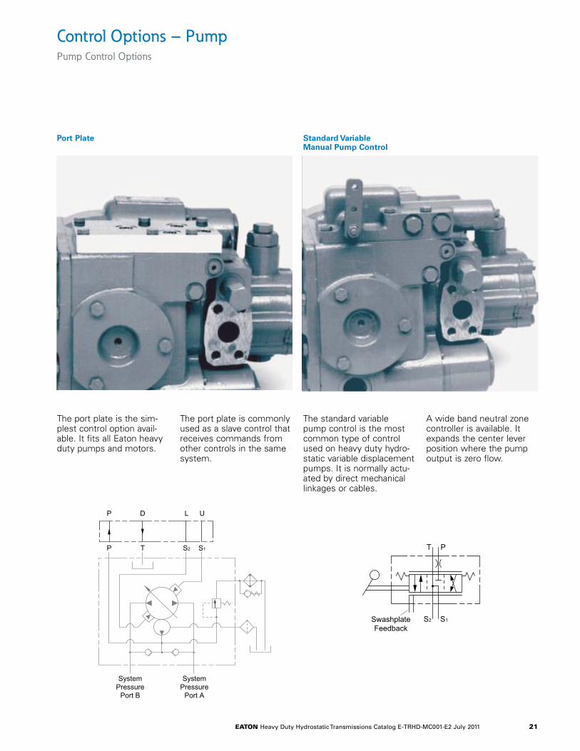
Control Options – PumpPump Control Options
Port Plate Standard Variable Manual Pump Control
The port plate is the sim-plest control option avail-able. It fits all Eaton heavy duty pumps and motors.
The port plate is commonly used as a slave control that receives commands from other controls in the same system.
The standard variable pump control is the most common type of control used on heavy duty hydro-static variable displacement pumps. It is normally actu-ated by direct mechanical linkages or cables.
A wide band neutral zone controller is available. It expands the center lever position where the pump output is zero flow.
Port Plate Standard VariablePump Control
PT
S1S2SwashplateFeedback
P T S1S2
SystemPressure
Port B
SystemPressure
Port A
P D UL
eaton Heavy Duty Hydrostatic Transmissions Catalog E-TRHD-MC001-E2 July 2011 22
Control Options – Pump
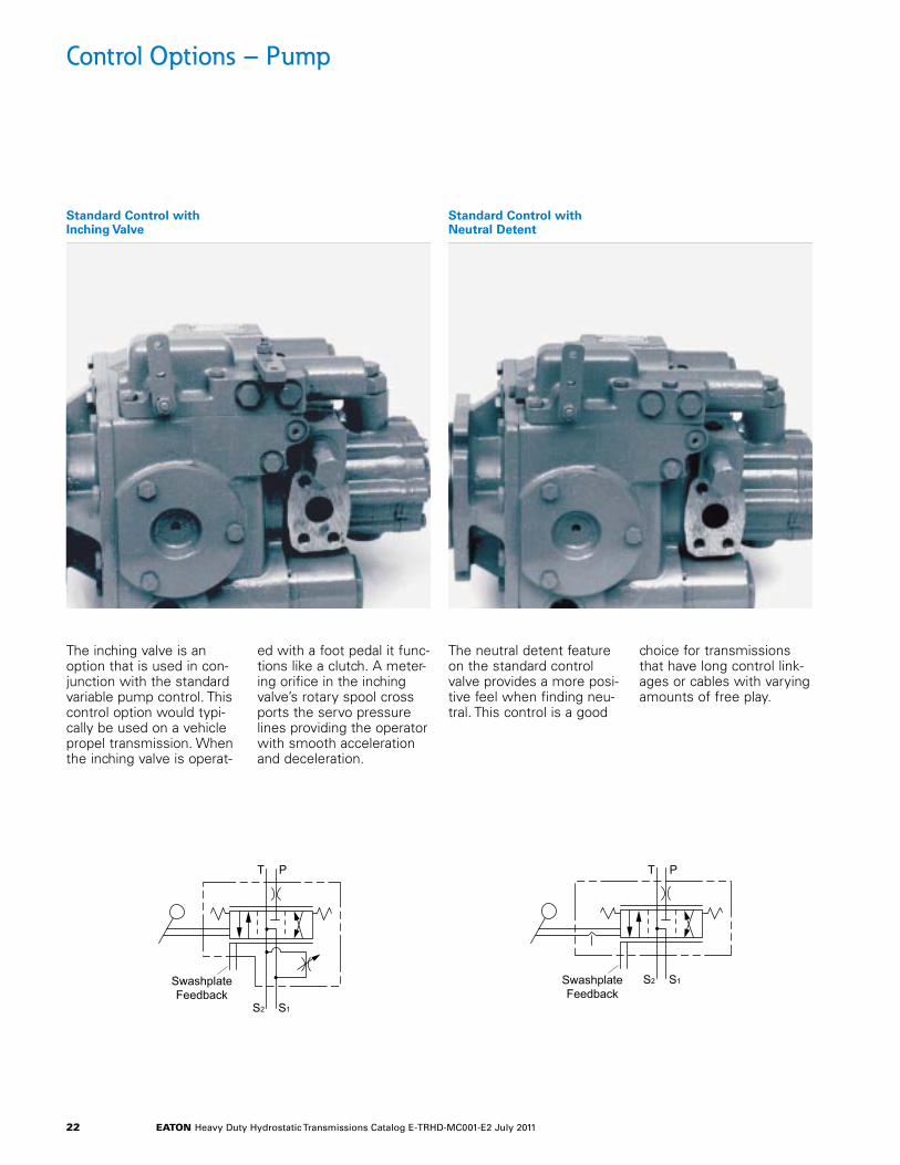
Standard Control with Inching Valve
Standard Control with Neutral Detent
The inching valve is an option that is used in con-junction with the standard variable pump control. This control option would typi-cally be used on a vehicle propel transmission. When the inching valve is operat-
ed with a foot pedal it func-tions like a clutch. A meter-ing orifice in the inching valve’s rotary spool cross ports the servo pressure lines providing the operator with smooth acceleration and deceleration.
The neutral detent feature on the standard control valve provides a more posi-tive feel when finding neu-tral. This control is a good
choice for transmissions that have long control link-ages or cables with varying amounts of free play.
Standard Control withInching Valve
Standard Control withNeutral Detent
PT
S1S2
SwashplateFeedback
PT
S1S2SwashplateFeedback
eaton Heavy Duty Hydrostatic Transmissions Catalog E-TRHD-MC001-E2 July 2011 23
Control Options – Pump
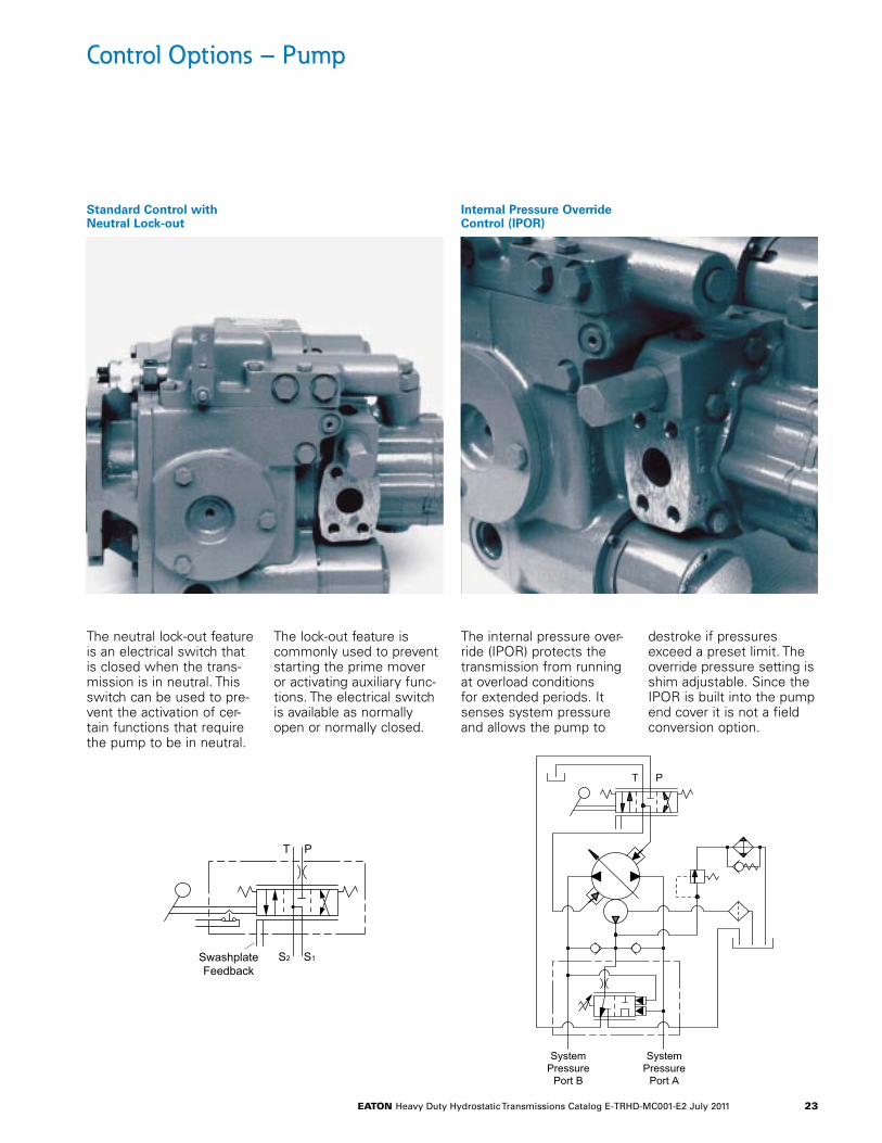
Standard Control with Neutral Lock-out
Internal Pressure Override Control (IPOR)
The neutral lock-out feature is an electrical switch that is closed when the trans-mission is in neutral. This switch can be used to pre-vent the activation of cer-tain functions that require the pump to be in neutral.
The lock-out feature is commonly used to prevent starting the prime mover or activating auxiliary func-tions. The electrical switch is available as normally open or normally closed.
The internal pressure over-ride (IPOR) protects the transmission from running at overload conditions for extended periods. It senses system pressure and allows the pump to
destroke if pressures exceed a preset limit. The override pressure setting is shim adjustable. Since the IPOR is built into the pump end cover it is not a field conversion option.
Internal Pressure OverrideControl (IPOR)
Standard Control withNeutral Lock-out
PT
S1S2SwashplateFeedback
P
SystemPressure
Port B
SystemPressure
Port A
T
eaton Heavy Duty Hydrostatic Transmissions Catalog E-TRHD-MC001-E2 July 2011 24
Control Options – Pump
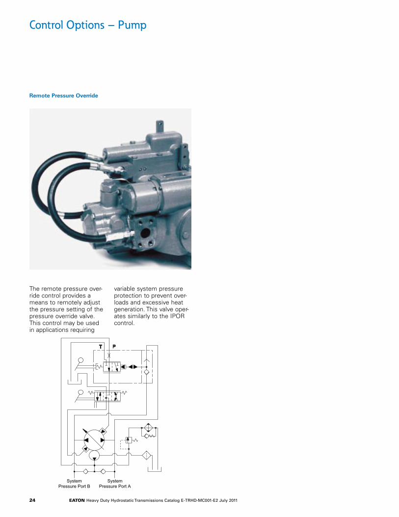
Remote Pressure Override
The remote pressure over-ride control provides a means to remotely adjust the pressure setting of the pressure override valve. This control may be used in applications requiring
variable system pressure protection to prevent over-loads and excessive heat generation. This valve oper-ates similarly to the IPOR control.
Remote PressureOverride
PT
SystemPressure Port B
SystemPressure Port A
eaton Heavy Duty Hydrostatic Transmissions Catalog E-TRHD-MC001-E2 July 2011 25
Control Option – Pump
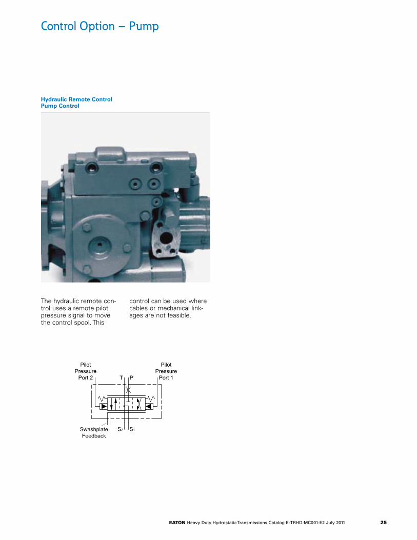
Hydraulic Remote Control Pump Control
The hydraulic remote con-trol uses a remote pilot pressure signal to move the control spool. This
control can be used where cables or mechanical link-ages are not feasible.
Hydraulic Remote ControlPump Control
PT
S1S2SwashplateFeedback
PilotPressure
Port 2
PilotPressure
Port 1

eaton Heavy Duty Hydrostatic Transmissions Catalog E-TRHD-MC001-E2 July 2011 26
Control Options – Pump
Destroke Control Destroke Solenoid
The heavy duty Destroke Control is a solenoid valve mounted on the standard variable pump control. When energized, the valve cross-ports control pres-sure allowing centering springs to bring the pump
out of stroke. It can be energized with a single switch, push-button, or dead man’s switch. The solenoid coil is available in 12 volt or 24 volt DC and normally open and normally closed configurations.
The heavy duty Destroke Solenoid is available to field convert the standard vari-able pump control into a destroke control.
An Anti-Stall Electronics Module is available to drive
a normally closed destroke valve. The electronic circuit monitors engine speed. When engine speed drops the anti-stall electronic reduce the pump’s dis-placement.
Anti-Stall Electronics Module
Anti-Stall Electronics Module
Destroke Control Destroke Solenoid
PT
S1S2
SwashplateFeedback
eaton Heavy Duty Hydrostatic Transmissions Catalog E-TRHD-MC001-E2 July 2011 27
Control Options – Variable Motor
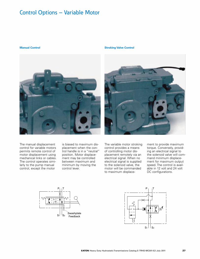
Manual Control Stroking Valve Control
The manual displacement control for variable motors permits remote control of motor displacement using mechanical links or cables. The control operates simi-larly to the pump manual control, except the motor
is biased to maximum dis-placement when the con-trol handle is in a “neutral” position. Motor displace-ment may be controlled between maximum and minimum by moving the control lever.
The variable motor stroking control provides a means of controlling motor dis-placement remotely via an electrical signal. When no electrical signal is supplied to the solenoid valve, the motor will be commanded to maximum displace-
ment to provide maximum torque. Conversely, provid-ing an electrical signal to the solenoid valve will com-mand minimum displace-ment for maximum output speed. The control is avail-able in 12 volt and 24 volt DC configurations.
Manual Control
P T
S1 S2
Stroking Valve Control
P T
S1 S2SwashplateFeedback
eaton Heavy Duty Hydrostatic Transmissions Catalog E-TRHD-MC001-E2 July 2011 28
Control Options – Variable Motor
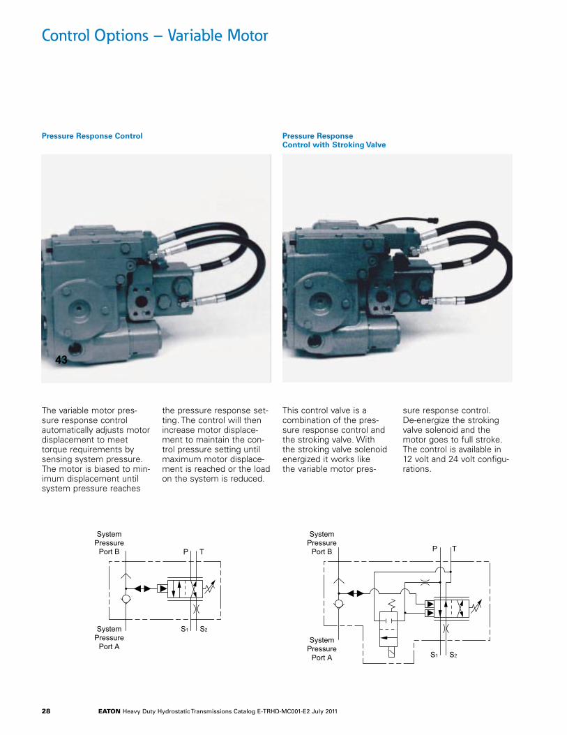
Pressure Response Control Pressure Response Control with Stroking Valve
The variable motor pres-sure response control automatically adjusts motor displacement to meet torque requirements by sensing system pressure. The motor is biased to min-imum displacement until system pressure reaches
the pressure response set-ting. The control will then increase motor displace-ment to maintain the con-trol pressure setting until maximum motor displace-ment is reached or the load on the system is reduced.
This control valve is a combination of the pres-sure response control and the stroking valve. With the stroking valve solenoid energized it works like the variable motor pres-
sure response control. De-energize the stroking valve solenoid and the motor goes to full stroke. The control is available in 12 volt and 24 volt configu-rations.
P T
S1 S2
SystemPressure
Port B
SystemPressure
Port A
Pressure Response Control
43
Pressure ResponseControl with Stroking Valve
P T
S1 S2
SystemPressure
Port B
SystemPressure
Port A
eaton Heavy Duty Hydrostatic Transmissions Catalog E-TRHD-MC001-E2 July 2011 29
Control Options – Variable Motor
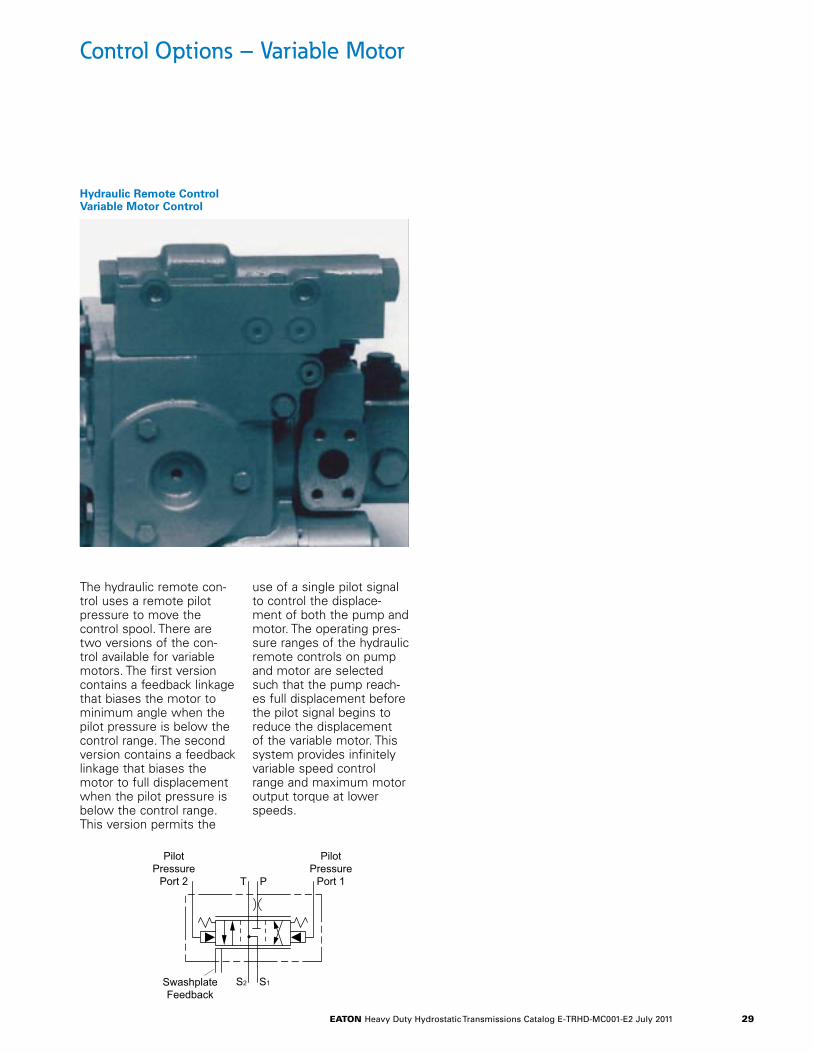
Hydraulic Remote Control Variable Motor Control
The hydraulic remote con-trol uses a remote pilot pressure to move the control spool. There are two versions of the con-trol available for variable motors. The first version contains a feedback linkage that biases the motor to minimum angle when the pilot pressure is below the control range. The second version contains a feedback linkage that biases the motor to full displacement when the pilot pressure is below the control range. This version permits the
use of a single pilot signal to control the displace-ment of both the pump and motor. The operating pres-sure ranges of the hydraulic remote controls on pump and motor are selected such that the pump reach-es full displacement before the pilot signal begins to reduce the displacement of the variable motor. This system provides infinitely variable speed control range and maximum motor output torque at lower speeds.
Hydraulic Remote ControlVariable Motor Control
PT
S1S2SwashplateFeedback
PilotPressure
Port 2
PilotPressure
Port 1
eaton Heavy Duty Hydrostatic Transmissions Catalog E-TRHD-MC001-E2 July 2011 30
*Refer to page 18 for for SAE B torque ratings.
29,0[1.14]
ChargePump
MountingSurface
57,2[2.25]
G19,1[.75]
Auxiliary Mounting Surface41,4 [1.63] MaximumAllowable Shaft ProtrusionGasket supplied as looseitem to be installed onmounting surface prior toassembly of auxiliarypump.
Spline to mate withinternal involute flatroot side fit, 13 tooth16/32 pitch, 30° pressureangle, per ANSI B-92.1-1970
73,02[2.875]
2 Places
146,05[5.750]
2 Places
Auxiliary mounting holes1/2-13 UNC-2B thread thru4 places.
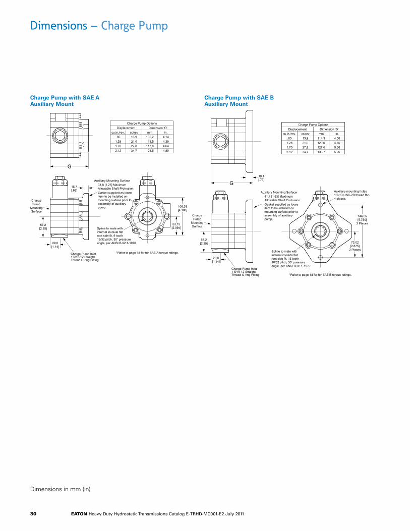
Charge Pump OptionsDisplacement Dimension 'G'
cu.in./rev. cc/rev in.mm.851.281.70
13,921,027,8
4.504.755.00
114,3120,6127,0
2.12 34,7 5.25133,7
Charge Pump Inlet1 5/16-12 StraightThread O-ring Fitting
Charge Pump with SAE B Auxiliary Mount
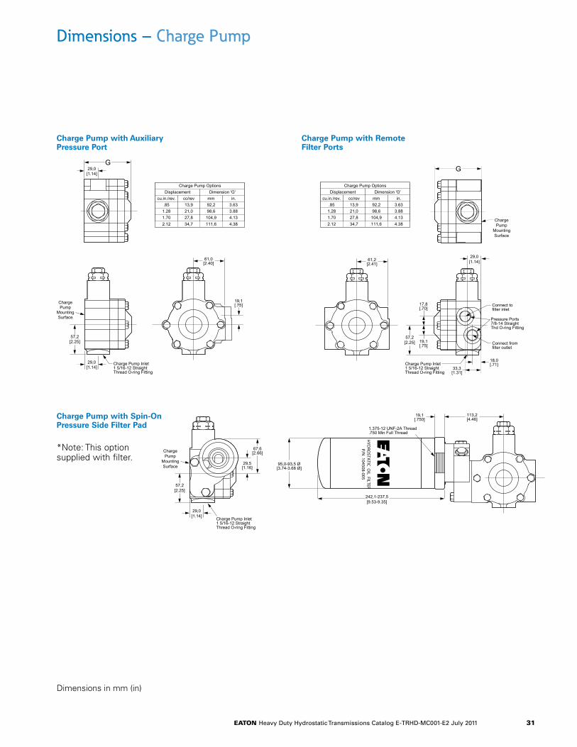
Dimensions – Charge Pump
Charge Pump with SAE A Auxiliary Mount
Charge Pump with SAE B Auxiliary Mount
Dimensions in mm (in)
29,0[1.14]
ChargePump
MountingSurface
57,2[2.25]
Charge Pump Inlet1 5/16-12 StraightThread O-ring Fitting
G
15,7[.62]
Auxiliary Mounting Surface
*Refer to page 18 for for SAE A torque ratings.
31,8 [1.25] MaximumAllowable Shaft ProtrusionGasket supplied as looseitem to be installed onmounting surface prior toassembly of auxiliarypump.
Spline to mate withinternal involute flatroot side fit, 9 tooth16/32 pitch, 30° pressureangle, per ANSI B-92.1-1970
53,19[2.094]
106,38[4.188]
Charge Pump OptionsDisplacement Dimension 'G'
cu.in./rev. cc/rev in.mm.851.281.70
13,921,027,8
4.144.394.64
105,2111,5117,8
2.12 34,7 4.89124,5
Charge Pump with SAE A Auxiliary Mount
eaton Heavy Duty Hydrostatic Transmissions Catalog E-TRHD-MC001-E2 July 2011 31
Dimensions – Charge Pump
Charge Pump with Auxiliary Pressure Port
Charge Pump with Remote Filter Ports
Charge Pump with Spin-On Pressure Side Filter Pad
*Note: This option supplied with filter.
Dimensions in mm (in)
Charge Pump OptionsDisplacement Dimension 'G'
cu.in./rev. cc/rev in.mm.851.281.70
13,921,027,8
3.633.884.13
92,298,6104,9
2.12 34,7 4.38111,6
29,0[1.14]
ChargePump
MountingSurface
57,2[2.25]
Charge Pump Inlet1 5/16-12 StraightThread O-ring Fitting
19,1[.75]
61,0[2.40]
29,0[1.14]
G
Charge Pump with Auxiliary Pressure Port
Charge Pump OptionsDisplacement Dimension 'G'
cu.in./rev. cc/rev in.mm.851.281.70
13,921,027,8
3.633.884.13
92,298,6104,9
2.12 34,7 4.38111,6ChargePump
MountingSurface
57,2[2.25]
Charge Pump Inlet1 5/16-12 StraightThread O-ring Fitting
17,8[.70]
61,2[2.41]
G
29,0[1.14]
18,0[.71]
33,3[1.31]
19,1[.75]
Pressure Ports7/8-14 StraightThd O-ring Fitting
Connect fromfilter outlet
Connect tofilter inlet
Charge Pump with Remote Filter Ports
HYD
ROSTA
TIC OIL FILTER
P/N 104508-005
Charge Pump with Spin-OnPressure Side Filter Pad*Note: This option suppliedwith filter.
29,0[1.14]
242,1-237,5[9.53-9.35]
ChargePump
MountingSurface
57,2[2.25]
Charge Pump Inlet1 5/16-12 StraightThread O-ring Fitting
19,1[.750]
113,2[4.46]
29,5[1.16]
67,6[2.66]
95,0-93,5 Ø[3.74-3.68 Ø]
1.375-12 UNF-2A Thread.750 Min Full Thread
eaton Heavy Duty Hydrostatic Transmissions Catalog E-TRHD-MC001-E2 July 2011 32
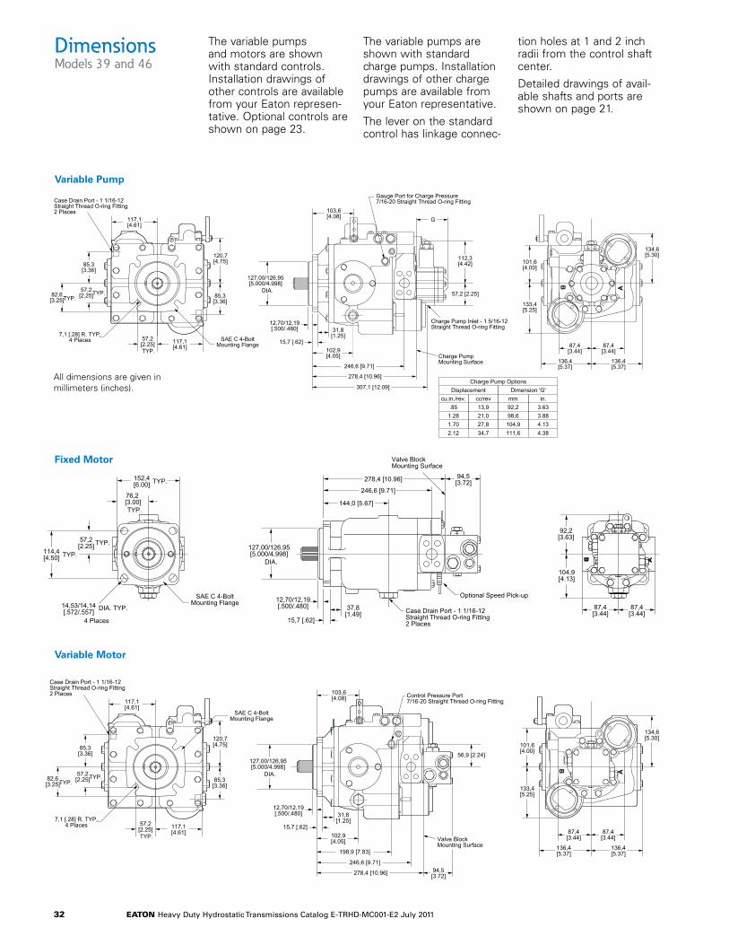
Variable Pump
Charge Pump OptionsDisplacement Dimension 'G'
cu.in./rev. cc/rev in.mm.85
1.281.70
13,921,027,8
3.633.884.13
92,298,6
104,92.12 34,7 4.38111,6
B
A
133,4[5.25]
134,6[5.30]
101,6[4.00]
127,00/126,95[5.000/4.998]
DIA.
12,70/12,19[.500/.480] 31,8
[1.25]15,7 [.62]
102,9[4.05]
246,6 [9.71]
278,4 [10.96]
307,1 [12.09]
Charge PumpMounting Surface
Charge Pump Inlet - 1 5/16-12Straight Thread O-ring Fitting
57,2 [2.25]
112,3[4.42]
G
Gauge Port for Charge Pressure7/16-20 Straight Thread O-ring Fitting
103,6[4.08]
57,2[2.25]TYP.
85,3[3.36]
82,6[3.25]TYP.
57,2[2.25]TYP.
117,1[4.61]
117,1[4.61]
7,1 [.28] R. TYP.4 Places SAE C 4-Bolt
Mounting Flange
Case Drain Port - 1 1/16-12Straight Thread O-ring Fitting2 Places
85,3[3.36]
120,7[4.75]
87,4[3.44]
87,4[3.44]
136,4[5.37]
136,4[5.37]
Dimensions Models 39 and 46
Variable Pump
Fixed Motor
Variable Motor
Fixed Motor
57,2[2.25]
114,4[4.50] TYP.
TYP.
76,2[3.00]TYP.
152,4[6.00] TYP.
14,53/14,14[.572/.557] DIA. TYP.
4 Places
127,00/126,95[5.000/4.998]
DIA.
Case Drain Port - 1 1/16-12Straight Thread O-ring Fitting2 Places
12,70/12,19[.500/.480]
15,7 [.62]
37,8[1.49]
144,0 [5.67]
246,6 [9.71]
278,4 [10.96] 94,5[3.72]
Valve BlockMounting Surface
Optional Speed Pick-up
B
A
87,4[3.44]
87,4[3.44]
92,2[3.63]
104,9[4.13]
SAE C 4-BoltMounting Flange
57,2[2.25]TYP.
85,3[3.36]
82,6[3.25]TYP.
57,2[2.25]TYP.
117,1[4.61]
117,1[4.61]
7,1 [.28] R. TYP.4 Places
Case Drain Port - 1 1/16-12Straight Thread O-ring Fitting2 Places
85,3[3.36]
120,7[4.75]
B
A
133,4[5.25]
101,6[4.00]
134,6[5.30]
127,00/126,95[5.000/4.998]
DIA.
12,70/12,19[.500/.480] 31,8
[1.25]15,7 [.62]
102,9[4.05]
246,6 [9.71]
278,4 [10.96]
198,9 [7.83]
Valve BlockMounting Surface
56,9 [2.24]
Control Pressure Port7/16-20 Straight Thread O-ring Fitting
103,6[4.08]
94,5[3.72]
SAE C 4-BoltMounting Flange
136,4[5.37]
136,4[5.37]
87,4[3.44]
87,4[3.44]
Variable Motor
The variable pumps and motors are shown with standard controls. Installation drawings of other controls are available from your Eaton represen-tative. Optional controls are shown on page 23.
The variable pumps are shown with standard charge pumps. Installation drawings of other charge pumps are available from your Eaton representative.
The lever on the standard control has linkage connec-
tion holes at 1 and 2 inch radii from the control shaft center.
Detailed drawings of avail-able shafts and ports are shown on page 21.
All dimensions are given in millimeters (inches).
eaton Heavy Duty Hydrostatic Transmissions Catalog E-TRHD-MC001-E2 July 2011 33
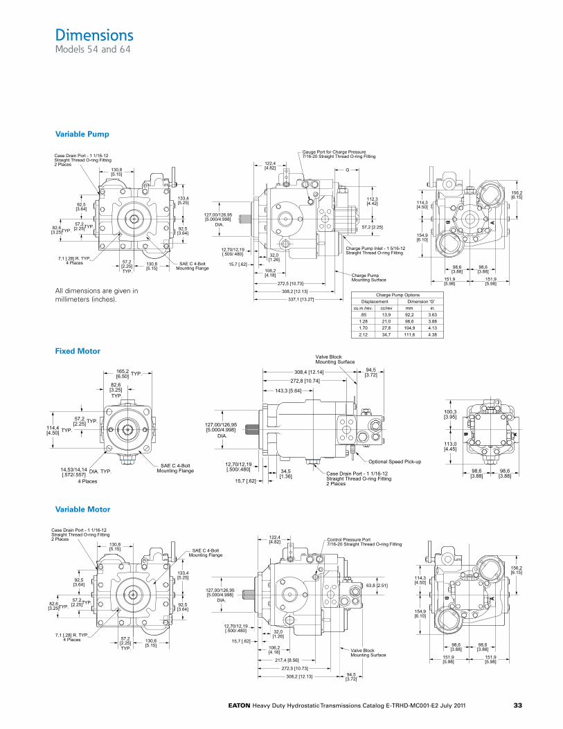
Dimensions Models 54 and 64
Variable Pump
Fixed Motor
Variable Motor
57,2[2.25]
114,4[4.50] TYP.
TYP.
82,6[3.25]TYP.
165,2[6.50] TYP.
14,53/14,14[.572/.557] DIA. TYP.
4 Places
127,00/126,95[5.000/4.998]
DIA.
Case Drain Port - 1 1/16-12Straight Thread O-ring Fitting2 Places
12,70/12,19[.500/.480]
15,7 [.62]
34,5[1.36]
143,3 [5.64]
272,8 [10.74]
308,4 [12.14] 94,5[3.72]
Valve BlockMounting Surface
B
A
98,6[3.88]
98,6[3.88]
100,3[3.95]
113,0[4.45]
Optional Speed Pick-upSAE C 4-Bolt
Mounting Flange
Fixed Motor
Variable Motor
57,2[2.25]TYP.
92,5[3.64]
82,6[3.25]TYP.
57,2[2.25]TYP.
130,6[5.15]
130,8[5.15]
7,1 [.28] R. TYP.4 Places
Case Drain Port - 1 1/16-12Straight Thread O-ring Fitting2 Places
92,5[3.64]
133,4[5.25]
B
A
154,9[6.10]
114,3[4.50]
156,2[6.15]
127,00/126,95[5.000/4.998]
DIA.
12,70/12,19[.500/.480] 32,0
[1.26]15,7 [.62]
106,2[4.18]
272,5 [10.73]
308,2 [12.13]
217,4 [8.56]
Valve BlockMounting Surface
63,8 [2.51]
Control Pressure Port7/16-20 Straight Thread O-ring Fitting
122,4[4.82]
94,5[3.72]
SAE C 4-BoltMounting Flange
98,6[3.88]
98,6[3.88]
151,9[5.98]
151,9[5.98]
Variable Pump
B
A
154,9[6.10]
156,2[6.15]
114,3[4.50]
127,00/126,95[5.000/4.998]
DIA.
12,70/12,19[.500/.480] 32,0
[1.26]15,7 [.62]
106,2[4.18]
272,5 [10.73]
308,2 [12.13]
337,1 [13.27]
Charge PumpMounting Surface
Charge Pump Inlet - 1 5/16-12Straight Thread O-ring Fitting
57,2 [2.25]
112,3[4.42]
G
Gauge Port for Charge Pressure7/16-20 Straight Thread O-ring Fitting
122,4[4.82]
57,2[2.25]TYP.
92,5[3.64]
82,6[3.25]TYP.
57,2[2.25]TYP.
130,8[5.15]
130,8[5.15]
7,1 [.28] R. TYP.4 Places
Case Drain Port - 1 1/16-12Straight Thread O-ring Fitting2 Places
92,5[3.64]
133,4[5.25]
Charge Pump OptionsDisplacement Dimension 'G'
cu.in./rev. cc/rev in.mm.851.281.70
13,921,027,8
3.633.884.13
92,298,6104,9
2.12 34,7 4.38111,6
SAE C 4-BoltMounting Flange 98,6
[3.88]98,6[3.88]
151,9[5.98]
151,9[5.98]
All dimensions are given in millimeters (inches).
eaton Heavy Duty Hydrostatic Transmissions Catalog E-TRHD-MC001-E2 July 2011 34
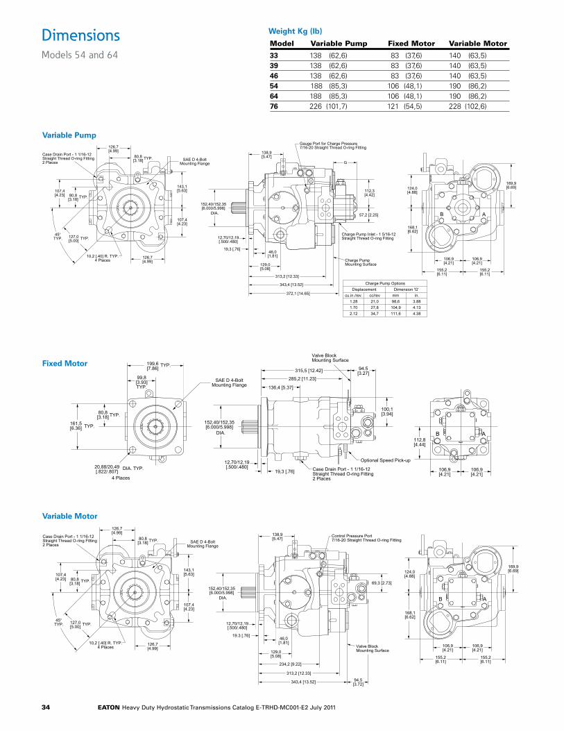
Dimensions Models 54 and 64
Variable Pump
Fixed Motor
Variable Motor
Fixed Motor199,6[7.86]
TYP.
99,8[3.93]TYP.
80,8[3.18] TYP.
161,5[6.36] TYP.
20,88/20,49[.822/.807]
DIA. TYP.
4 Places
152,40/152,35[6.000/5.998]
DIA.
12,70/12,19[.500/.480]
19,3 [.76]
136,4 [5.37]
285,2 [11.23]
315,5 [12.42] 94.5[3.27]
100,1[3.94]
Case Drain Port - 1 1/16-12Straight Thread O-ring Fitting2 Places
Valve BlockMounting Surface
B A
106,9[4.21]
106,9[4.21]
112,8[4.44]
Optional Speed Pick-up
SAE D 4-BoltMounting Flange
Variable Motor
127,0[5.00] TYP.
107,4[4.23] 80,8
[3.18] TYP.
45°TYP.
80,8[3.18]TYP.
126,7[4.99]
126,7[4.99]
107,4[4.23]
10,2 [.40] R. TYP.4 Places
143,1[5.63]
Case Drain Port - 1 1/16-12Straight Thread O-ring Fitting2 Places
B A
124,0[4.88]
168,1[6.62]
106,9[4.21]
106,9[4.21]
155,2[6.11]
155,2[6.11]
169,9[6.69]
152,40/152,35[6.000/5.998]
DIA.
12,70/12,19[.500/.480]
19.3 [.76]46,0[1.81]
129,0[5.08]
313,2 [12.33]
343,4 [13.52]
234,2 [9.22]
Valve BlockMounting Surface
138,9[5.47]
94,5[3.72]
69,3 [2.73]
Control Pressure Port7/16-20 Straight Thread O-ring FittingSAE D 4-Bolt
Mounting Flange
Variable Pump
127,0[5.00] TYP.
107,4[4.23] 80,8
[3.18] TYP.
45°TYP.
80,8[3.18]TYP.
126,7[4.99]
126,7[4.99]
107,4[4.23]
10,2 [.40] R. TYP.4 Places
143,1[5.63]
Case Drain Port - 1 1/16-12Straight Thread O-ring Fitting2 Places
152,40/152,35[6.000/5.998]
DIA.
12,70/12,19[.500/.480]
19,3 [.76]46,0[1.81]
129,0[5.08]
313,2 [12.33]
343,4 [13.52]
372,1 [14.65]
Charge PumpMounting Surface
Charge Pump Inlet - 1 5/16-12Straight Thread O-ring Fitting
Gauge Port for Charge Pressure7/16-20 Straight Thread O-ring Fitting
138,9[5.47]
G
112,3[4.42]
57,2 [2.25] B A
124,0[4.88]
168,1[6.62]
106,9[4.21]
106,9[4.21]
155,2[6.11]
155,2[6.11]
169,9[6.69]
Charge Pump OptionsDisplacement Dimension 'G'
cu.in./rev. cc/rev in.mm1.281.70
21,027,8
3.884.13
98,6104,9
2.12 34,7 4.38111,6
SAE D 4-BoltMounting Flange
Model Variable Pump Fixed Motor Variable Motor
33 138 (62,6) 83 (37,6) 140 (63,5)39 138 (62,6) 83 (37,6) 140 (63,5)46 138 (62,6) 83 (37,6) 140 (63,5)54 188 (85,3) 106 (48,1) 190 (86,2)64 188 (85,3) 106 (48,1) 190 (86,2)76 226 (101,7) 121 (54,5) 228 (102,6)
Heavy Duty Component Approximate Weights
lb (Kg)
Weight Kg (lb)
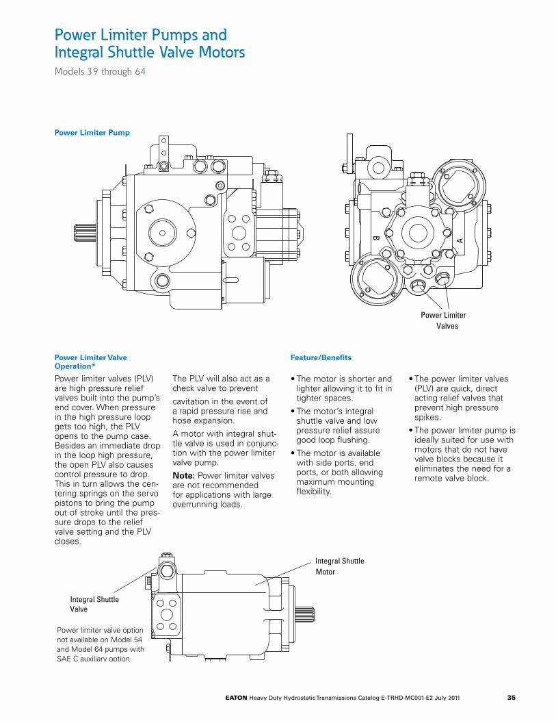
eaton Heavy Duty Hydrostatic Transmissions Catalog E-TRHD-MC001-E2 July 2011 35
Power Limiter Pumps and Integral Shuttle Valve Motors Models 39 through 64
Power Limiter Pump
Power limiter valves (PLV) are high pressure relief valves built into the pump’s end cover. When pressure in the high pressure loop gets too high, the PLV opens to the pump case. Besides an immediate drop in the loop high pressure, the open PLV also causes control pressure to drop. This in turn allows the cen-tering springs on the servo pistons to bring the pump out of stroke until the pres-sure drops to the relief valve setting and the PLV closes.
The PLV will also act as a check valve to prevent
cavitation in the event of a rapid pressure rise and hose expansion.
A motor with integral shut-tle valve is used in conjunc-tion with the power limiter valve pump.
Note: Power limiter valves are not recommended for applications with large overrunning loads.
B
A
Power LimiterValves
Power LimiterPump
• The motor is shorter and lighter allowing it to fit in tighter spaces.
• The motor’s integral shuttle valve and low pressure relief assure good loop flushing.
• The motor is available with side ports, end ports, or both allowing maximum mounting flexibility.
• The power limiter valves (PLV) are quick, direct acting relief valves that prevent high pressure spikes.
• The power limiter pump is ideally suited for use with motors that do not have valve blocks because it eliminates the need for a remote valve block.
Power Limiter Valve Operation*
Feature/Benefits
Integral ShuttleValve
Integral ShuttleMotor
Power limiter valve optionnot available on Model 54and Model 64 pumps withSAE C auxiliary option.
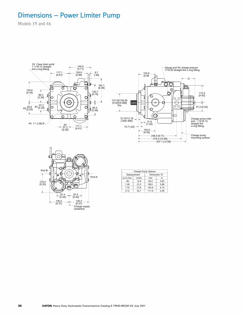
eaton Heavy Duty Hydrostatic Transmissions Catalog E-TRHD-MC001-E2 July 2011 36
Dimensions – Power Limiter Pump Models 39 and 46
Models 33, 39, and 46 Power Limiter Pumps
4X57.2[2.25]
57.2[2.25]
4X 7.1 [.28] R.
82.6[3.25]
85.3[3.36]
2X Case drain ports 1 1/16-12 straightthd o-ring fitting.
117.1[4.61]
134.6[5.30]
162.1[6.38]
120.7[4.75]
145.0[5.71]
126.0[4.96]
9.7[.38]
4X4X 85.3
[3.36]
117.1[4.61] 102.9
[4.05]
31.8[1.25]
246.6 [9.71]278.4 [10.96]
307.1 [12.09]
127.00/126.95[5.000/4.998]
Dia.
12.70/12.19[.500/.480]
15.7 [.62]
103.6[4.08
G
Gauge port for charge prssure.7/16-20 straight thd o-ring fitting.
Charge pumpmounting surface
Charge pump inletport. 1 5/16-12straight thdo-ring fitting.
57.2 [2.25]
112.3[4.42]
B
A
87.4[3.44]
87.4[3.44]
133.4[5.25]
136.4[5.37]
Port-A
Port-B
Charge supplycenterline
136.4[5.37]
Charge Pump OptionsDisplacement Dimension 'G'
cu.in./rev. cc/rev in.mm.851.281.70
13,921,027,8
3.633.884.13
92.298.6104.9
2.12 34,7 4.38111.6
Models 33, 39, and 46 Power Limiter Pumps
4X57.2
[2.25]
57.2[2.25]
4X 7.1 [.28] R.
82.6[3.25]
85.3[3.36]
2X Case drain ports 1 1/16-12 straightthd o-ring fitting.
117.1[4.61]
134.6[5.30]
162.1[6.38]
120.7[4.75]
145.0[5.71]
126.0[4.96]
9.7[.38]
4X4X 85.3
[3.36]
117.1[4.61] 102.9
[4.05]
31.8[1.25]
246.6 [9.71]278.4 [10.96]
307.1 [12.09]
127.00/126.95[5.000/4.998]
Dia.
12.70/12.19[.500/.480]
15.7 [.62]
103.6[4.08
G
Gauge port for charge prssure.7/16-20 straight thd o-ring fitting.
Charge pumpmounting surface
Charge pump inletport. 1 5/16-12straight thdo-ring fitting.
57.2 [2.25]
112.3[4.42]
B
A
87.4[3.44]
87.4[3.44]
133.4[5.25]
136.4[5.37]
Port-A
Port-B
Charge supplycenterline
136.4[5.37]
Charge Pump OptionsDisplacement Dimension 'G'
cu.in./rev. cc/rev in.mm.85
1.281.70
13,921,027,8
3.633.884.13
92.298.6
104.92.12 34,7 4.38111.6
Models 33, 39, and 46 Power Limiter Pumps
4X57.2[2.25]
57.2[2.25]
4X 7.1 [.28] R.
82.6[3.25]
85.3[3.36]
2X Case drain ports 1 1/16-12 straightthd o-ring fitting.
117.1[4.61]
134.6[5.30]
162.1[6.38]
120.7[4.75]
145.0[5.71]
126.0[4.96]
9.7[.38]
4X4X 85.3
[3.36]
117.1[4.61] 102.9
[4.05]
31.8[1.25]
246.6 [9.71]278.4 [10.96]
307.1 [12.09]
127.00/126.95[5.000/4.998]
Dia.
12.70/12.19[.500/.480]
15.7 [.62]
103.6[4.08
G
Gauge port for charge prssure.7/16-20 straight thd o-ring fitting.
Charge pumpmounting surface
Charge pump inletport. 1 5/16-12straight thdo-ring fitting.
57.2 [2.25]
112.3[4.42]
B
A
87.4[3.44]
87.4[3.44]
133.4[5.25]
136.4[5.37]
Port-A
Port-B
Charge supplycenterline
136.4[5.37]
Charge Pump OptionsDisplacement Dimension 'G'
cu.in./rev. cc/rev in.mm.851.281.70
13,921,027,8
3.633.884.13
92.298.6104.9
2.12 34,7 4.38111.6

eaton Heavy Duty Hydrostatic Transmissions Catalog E-TRHD-MC001-E2 July 2011 37
Dimensions – Power Limiter Pump Models 54 and 64
Models 54 and 64 Power Limiter Pumps
106.2[4.18]
32.0[1.26]
272.5 [10.73]308.2 [12.13]
337.1 [13.27]
127.00/126.95[5.000/4.998]
Dia.
12.70/12.19[.500/.480]
15.7 [.62]
122.4[4.82]
G
Charge pumpmounting surface
57.2 [2.25]
112.3[4.42]
Gauge port for charge prssure.7/16-20 straight thd o-ring fitting.
Charge pump inletport. 1 5/16-12straight thdo-ring fitting.4X
57.2[2.25]
57.2[2.25]
4X 7.5 [.30] R.
82.6[3.25]
92.5[3.64]
130.8[5.15]
156.2[6.15]
174.8[6.88]
133.4[5.25]
153.4[6.04]
134.4[5.29]
9.7[.38]
4X4X 92.5
[3.64]
130.8[5.15]
2X Case drain ports 1 1/16-12 straightthd o-ring fitting.
B
A
98.6[3.88]
98.6[3.88]
154.9[6.10]
151.9[5.98]
Port-A
Port-B
Charge supplycenterline
151.9[5.98]
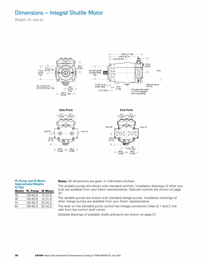
eaton Heavy Duty Hydrostatic Transmissions Catalog E-TRHD-MC001-E2 July 2011 38
Dimensions – Integral Shuttle Motor Models 39, and 46
CWCCW
B A
72.1[2.84]
72.1[2.84]
104.9[4.13]
Port 'A'Port 'B'
98.6[3.88]
98.6[3.88]
49[1.93]2X
End Ports
76.2[3.00]Typ.
Typ.152.4[6.00]
Typ.57.2[2.25]114.4
[4.50]Typ.
4X 14.53/14.14[.572/.557] Dia. Typ.
92.2[3.63]
B A
Port 'A'Port 'B'
72.1[2.84]
72.1[2.84]
104.9[4.13]
98.6[3.88]
98.6[3.88]
Side Ports
122.9[4.84]
37.8[1.49]
15.7 [.62]
12.70/12.19[.500/.480]
127.00/126.95[5.000/4.998]
Dia.
144.0 [5.67]246.6 [9.71]
285.9 [11.26]
2X case drain ports1 1/16-12 straightthd o-ring fitting.
Models 33, 39, and 46 Integral Shuttle Motors
Optional SpeedPick-up
Notes: All dimensions are given in millimeters (inches).
The variable pumps are shown with standard controls. Installation drawings of other con-trols are available from your Eaton representative. Optional controls are shown on page 23.
The variable pumps are shown with standard charge pumps. Installation drawings of other charge pumps are available from your Eaton representative.
The lever on the standard pump control has linkage connection holes at 1 and 2 inch radii from the control shaft center.
Detailed drawings of available shafts and ports are shown on page 21.
Model PL Pump IS Motor
39 138 (62,6) 70 (31,8)46 138 (62,6) 70 (31,8)54 188 (85,3) 93 (42,2)64 188 (85,3) 93 (42,2)
PL Pump and IS Motor Approximate Weights lb (Kg)
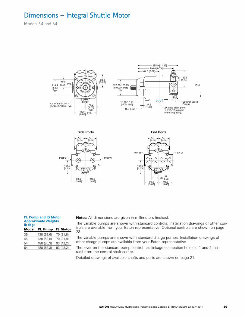
eaton Heavy Duty Hydrostatic Transmissions Catalog E-TRHD-MC001-E2 July 2011 39
Dimensions – Integral Shuttle Motor Models 54 and 64
CWCCW
B A
72.1[2.84]
72.1[2.84]
104.9[4.13]
Port 'A'Port 'B'
98.6[3.88]
98.6[3.88]
49[1.93]2X
End Ports
76.2[3.00]Typ.
Typ.152.4[6.00]
Typ.57.2[2.25]114.4
[4.50]Typ.
4X 14.53/14.14[.572/.557] Dia. Typ.
92.2[3.63]
B A
Port 'A'Port 'B'
72.1[2.84]
72.1[2.84]
104.9[4.13]
98.6[3.88]
98.6[3.88]
Side Ports
122.9[4.84]
37.8[1.49]
15.7 [.62]
12.70/12.19[.500/.480]
127.00/126.95[5.000/4.998]
Dia.
144.0 [5.67]246.6 [9.71]
285.9 [11.26]
2X case drain ports1 1/16-12 straightthd o-ring fitting.
Models 33, 39, and 46 Integral Shuttle Motors
Optional SpeedPick-up
Notes: All dimensions are given in millimeters (inches).
The variable pumps are shown with standard controls. Installation drawings of other con-trols are available from your Eaton representative. Optional controls are shown on page 23.
The variable pumps are shown with standard charge pumps. Installation drawings of other charge pumps are available from your Eaton representative.
The lever on the standard pump control has linkage connection holes at 1 and 2 inch radii from the control shaft center.
Detailed drawings of available shafts and ports are shown on page 21.
Model PL Pump IS Motor
39 138 (62,6) 70 (31,8)46 138 (62,6) 70 (31,8)54 188 (85,3) 93 (42,2)64 188 (85,3) 93 (42,2)
PL Pump and IS Motor Approximate Weights lb (Kg)
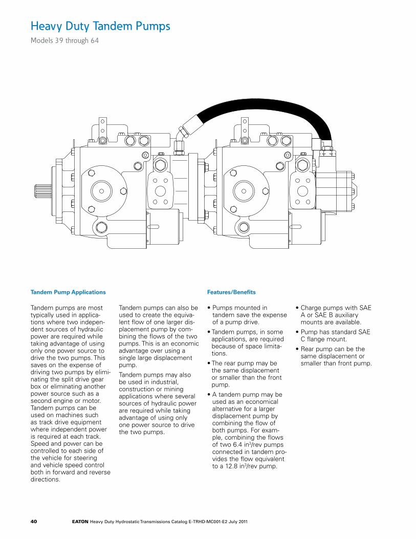
eaton Heavy Duty Hydrostatic Transmissions Catalog E-TRHD-MC001-E2 July 2011 40
Heavy Duty Tandem Pumps Models 39 through 64
Tandem Pump Applications Features/Benefits
Tandem pumps are most typically used in applica-tions where two indepen-dent sources of hydraulic power are required while taking advantage of using only one power source to drive the two pumps. This saves on the expense of driving two pumps by elimi-nating the split drive gear box or eliminating another power source such as a second engine or motor. Tandem pumps can be used on machines such as track drive equipment where independent power is required at each track. Speed and power can be controlled to each side of the vehicle for steering and vehicle speed control both in forward and reverse directions.
Tandem pumps can also be used to create the equiva-lent flow of one larger dis-placement pump by com-bining the flows of the two pumps. This is an economic advantage over using a single large displacement pump.
Tandem pumps may also be used in industrial, construction or mining applications where several sources of hydraulic power are required while taking advantage of using only one power source to drive the two pumps.
• Pumps mounted in tandem save the expense of a pump drive.
• Tandem pumps, in some applications, are required because of space limita-tions.
• The rear pump may be the same displacement or smaller than the front pump.
• A tandem pump may be used as an economical alternative for a larger displacement pump by combining the flow of both pumps. For exam-ple, combining the flows of two 6.4 in3/rev pumps connected in tandem pro-vides the flow equivalent to a 12.8 in3/rev pump.
• Charge pumps with SAE A or SAE B auxiliary mounts are available.
• Pump has standard SAE C flange mount.
• Rear pump can be the same displacement or smaller than front pump.
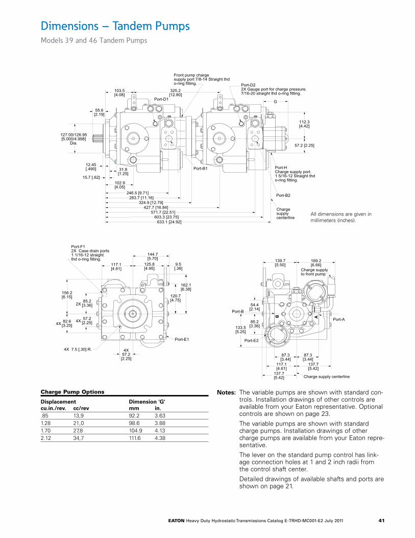
eaton Heavy Duty Hydrostatic Transmissions Catalog E-TRHD-MC001-E2 July 2011 41
Dimensions – Tandem PumpsModels 39 and 46 Tandem Pumps
Notes: The variable pumps are shown with standard con-trols. Installation drawings of other controls are available from your Eaton representative. Optional controls are shown on page 23.
The variable pumps are shown with standard charge pumps. Installation drawings of other charge pumps are available from your Eaton repre-sentative.
The lever on the standard pump control has link-age connection holes at 1 and 2 inch radii from the control shaft center.
Detailed drawings of available shafts and ports are shown on page 21.
B
A
137.7[5.42]
117.1[4.61]
87.3[3.44]
87.3[3.44]
133.5[5.25]
54.4[2.14]
85.2[3.36]
137.7[5.42]
Port-A
Port-B
Port-E2
139.7[5.50]
169.2[6.66]
Charge supplyto front pump
Charge supply centerline
246.5 [9.71]283.7 [11.16]
102.9[4.05]
31.8[1.25]
427.7 [16.84]571.7 [22.51]
603.3 [23.75]633.1 [24.92]
103.5[4.08]
325.2[12.80]
Port-D1
Port-D22X Gauge port for charge pressure.7/16-20 straight thd o-ring fitting.
Port-HCharge supply port.1 5/16-12 Straight thdo-ring fitting.
Chargesupplycenterline
57.2 [2.25]
112.3[4.42]
Port-B2
Port-B1
15.7 [.62]
12.45[.490]
127.00/126.95[5.000/4.998]
Dia.
55.6[2.19]
Front pump chargesupply port 7/8-14 Straight thdo-ring fitting.
324.9 [12.79]
G
Models 33, 39, and 46 Tandem Pumps
4X57.2[2.25]
57.2[2.25]
4X 7.5 [.30] R.
82.6[3.25]
85.2[3.36]
Port-F12X Case drain ports1 1/16-12 straightthd o-ring fitting.
117.1[4.61]
156.2[6.15]
2X
162.1[6.38]
120.7[4.75]
144.7[5.70]
125.8[4.95]
9.5[.38]
Port-E1
4X4X
Charge Pump options
Displacement Dimension 'G'cu.in./rev. cc/rev mm in..85 13,9 92.2 3.631.28 21,0 98.6 3.881.70 27,8 104.9 4.132.12 34,7 111.6 4.38
All dimensions are given in millimeters (inches).
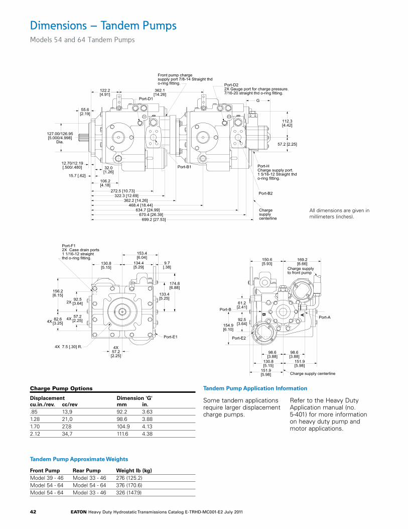
eaton Heavy Duty Hydrostatic Transmissions Catalog E-TRHD-MC001-E2 July 2011 42
Dimensions – Tandem PumpsModels 54 and 64 Tandem Pumps
Charge Pump options
Displacement Dimension 'G'cu.in./rev. cc/rev mm in..85 13,9 92.2 3.631.28 21,0 98.6 3.881.70 27,8 104.9 4.132.12 34,7 111.6 4.38
B
A
151.9[5.98]
130.8[5.15]
98.6[3.88]
98.6[3.88]
154.9[6.10]
61.2[2.41]
92.5[3.64]
151.9[5.98]
Port-A
Port-B
Port-E2
150.6[5.93]
169.2[6.66]
Charge supplyto front pump
Charge supply centerline
272.5 [10.73]322.3 [12.69]
106.2[4.18]
32.0[1.26]
468.4 [18.44]634.7 [24.99]
670.4 [26.39]699.2 [27.53]
122.2[4.91]
362.1[14.26]
Port-D1
Port-D22X Gauge port for charge pressure.7/16-20 straight thd o-ring fitting.
Port-HCharge supply port.1 5/16-12 Straight thdo-ring fitting.
Chargesupplycenterline
57.2 [2.25]
112.3[4.42]
Port-B2
Port-B1
15.7 [.62]
12.70/12.19[.500/.480]
127.00/126.95[5.000/4.998]
Dia.
55.6[2.19]
Front pump chargesupply port 7/8-14 Straight thdo-ring fitting.
362.2 [14.26]
G
Models 54 and 64 Tandem Pumps
4X57.2
[2.25]
57.2[2.25]
4X 7.5 [.30] R.
82.6[3.25]
92.5[3.64]
Port-F12X Case drain ports1 1/16-12 straightthd o-ring fitting.
130.8[5.15]
156.2[6.15]
2X
174.8[6.88]
133.4[5.25]
153.4[6.04]
134.4[5.29]
9.7[.38]
Port-E1
4X4X
Tandem Pump Approximate Weights
Front Pump Rear Pump Weight lb (kg)Model 39 - 46 Model 33 - 46 276 (125.2)Model 54 - 64 Model 54 - 64 376 (170.6)Model 54 - 64 Model 33 - 46 326 (147.9)
Tandem Pump Application Information
Some tandem applications require larger displacement charge pumps.
Refer to the Heavy Duty Application manual (no. 5-401) for more information on heavy duty pump and motor applications.
All dimensions are given in millimeters (inches).
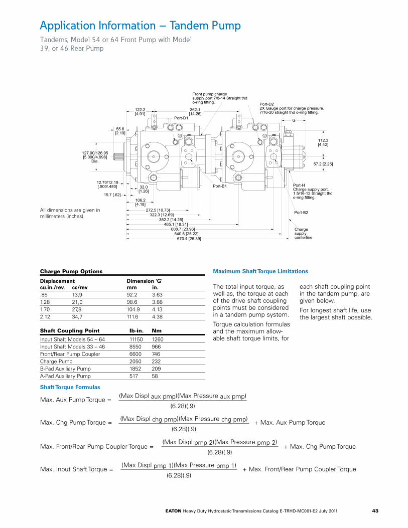
eaton Heavy Duty Hydrostatic Transmissions Catalog E-TRHD-MC001-E2 July 2011 43
Application Information – Tandem PumpTandems, Model 54 or 64 Front Pump with Model 39, or 46 Rear Pump
Maximum Shaft Torque Limitations
The total input torque, as well as, the torque at each of the drive shaft coupling points must be considered in a tandem pump system.
Torque calculation formulas and the maximum allow-able shaft torque limits, for
each shaft coupling point in the tandem pump, are given below.
For longest shaft life, use the largest shaft possible.
Shaft Coupling Point lb-in. nm
Input Shaft Models 54 – 64 11150 1260Input Shaft Models 33 – 46 8550 966Front/Rear Pump Coupler 6600 746Charge Pump 2050 232B-Pad Auxiliary Pump 1852 209A-Pad Auxiliary Pump 517 58
Shaft Torque Formulas
272.5 [10.73]322.3 [12.69]
106.2[4.18]
32.0[1.26]
465.1 [18.31]608.7 [23.96]
640.6 [25.22]670.4 [26.39]
122.2[4.91]
362.1[14.26]
Port-D1
Port-D22X Gauge port for charge pressure.7/16-20 straight thd o-ring fitting.
Port-HCharge supply port.1 5/16-12 Straight thdo-ring fitting.
Chargesupplycenterline
57.2 [2.25]
112.3[4.42]
Port-B2
Port-B1
15.7 [.62]
12.70/12.19[.500/.480]
127.00/126.95[5.000/4.998]
Dia.
55.6[2.19]
Front pump chargesupply port 7/8-14 Straight thdo-ring fitting.
362.2 [14.26]
G
Tandems, Model 54 or 64 Front Pump with Model 33, 39, or 46 Rear Pump
Charge Pump options
Displacement Dimension 'G'cu.in./rev. cc/rev mm in..85 13,9 92.2 3.631.28 21,0 98.6 3.881.70 27,8 104.9 4.132.12 34,7 111.6 4.38
Max. Aux Pump Torque =(Max Displ aux pmp)(Max Pressure aux pmp)
(6.28)(.9)
Max. Chg Pump Torque = + Max. Aux Pump Torque(Max Displ chg pmp)(Max Pressure chg pmp)
(6.28)(.9)
Max. Front/Rear Pump Coupler Torque =(Max Displ pmp 2)(Max Pressure pmp 2)
(6.28)(.9)+ Max. Chg Pump Torque
Max. Input Shaft Torque =(Max Displ pmp 1)(Max Pressure pmp 1)
(6.28)(.9)+ Max. Front/Rear Pump Coupler Torque
All dimensions are given in millimeters (inches).
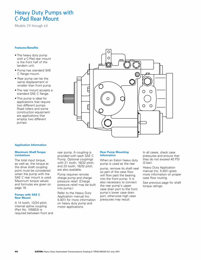
eaton Heavy Duty Hydrostatic Transmissions Catalog E-TRHD-MC001-E2 July 2011 44
Heavy Duty Pumps with C-Pad Rear Mount Models 39 through 64
Features/Benefits
• The heavy duty pump with a C-Pad rear mount is the front half of the tandem unit.
• Pump has standard SAE C flange mount.
• Rear pump can be the same displacement or smaller than front pump
• The rear mount accepts a standard SAE C flange.
• This pump is ideal for applications that require two different pumps. Road rollers and some construction equipment are applications that employ two different pumps.
Application Information
Maximum Shaft Torque Limitations
The total input torque, as well as, the torque at the drive shaft coupling point must be considered when the pump with the SAE C rear mount is used. Maximum torque values and formulas are given on page 18.
Pumps with SAE C Rear Mount
A 14 tooth, 12/24 pitch, internal spline coupling (Part No. 105853) is required between front and
rear pump. A coupling is provided with each SAE C Pump. Optional couplings with 21 tooth, 16/32 pitch; and 23 tooth, 16/32 pitch, are also available.
Pump requires remote charge pump and charge pressure relief. (Charge pressure relief may be built into pump.)
Refer to the Heavy Duty Application manual (no. 5-401) for more information on heavy duty pump and motor applications.
Rear Pump Mounting Information
When an Eaton heavy duty pump is used as the rear
pump, remove its shaft seal so part of the case flow will flow past the bearing into the front pump. It is also necessary to connect the rear pump's upper case drain port to the front pump's lower case drain port, otherwise high case pressures may result.
In all cases, check case pressures and ensure that they do not exceed 40 PSI (3 bar).
Heavy Duty Application manual (no. 5-401) gives more information on proper case flow routing.
See previous page for shaft torque ratings.
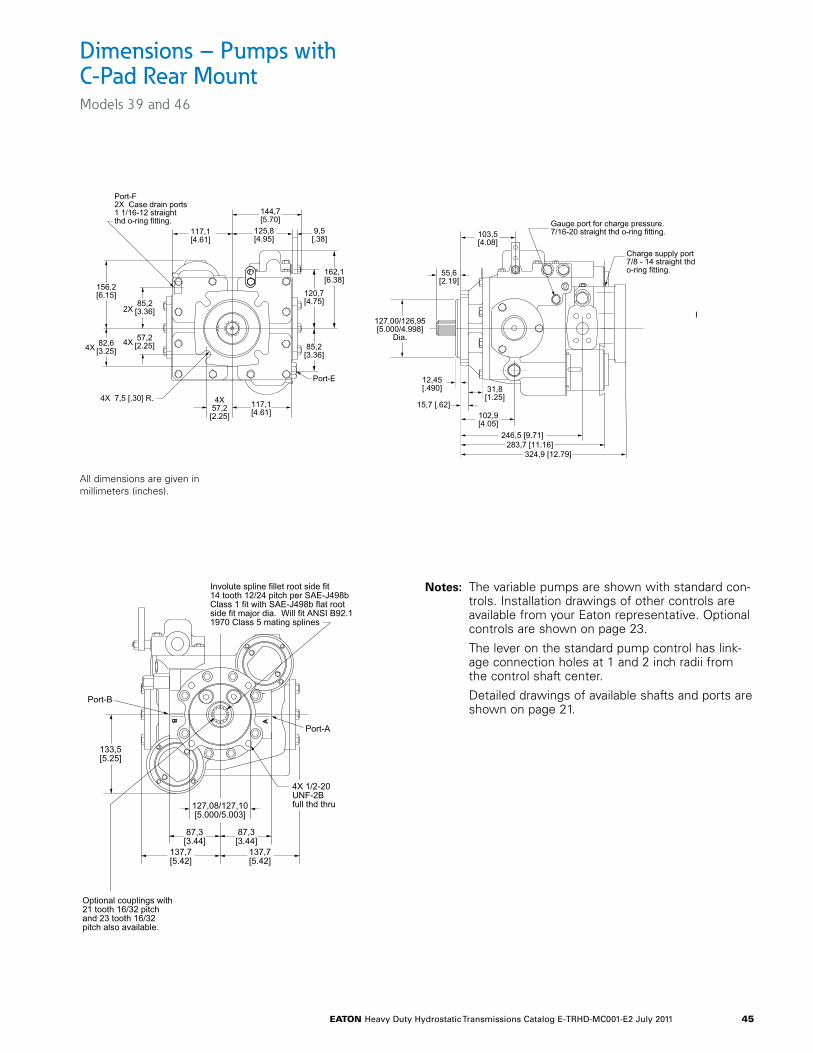
eaton Heavy Duty Hydrostatic Transmissions Catalog E-TRHD-MC001-E2 July 2011 45
Dimensions – Pumps with C-Pad Rear MountModels 39 and 46
Optional couplings with 21 tooth 16/32 pitch and 23 tooth 16/32 pitch also available.
A
B
Models 33, 39, and 46 Pumps with C-Pad Rear Mount
127,08/127,10[5.000/5.003]
4X 1/2-20UNF-2Bfull thd thru
Involute spline fillet root side fit14 tooth 12/24 pitch per SAE-J498bClass 1 fit with SAE-J498b flat rootside fit major dia. Will fit ANSI B92.11970 Class 5 mating splines
137,7[5.42]
87,3[3.44]
87,3[3.44]
133,5[5.25]
137,7[5.42]
Port-A
Port-B
4X57,2[2.25]
57,2[2.25]
4X 7,5 [.30] R.
82,6[3.25]
85,2[3.36]
Port-F2X Case drain ports1 1/16-12 straightthd o-ring fitting.
117,1[4.61]
156,2[6.15]
2X
162,1[6.38]
120,7[4.75]
144,7[5.70]
125,8[4.95]
9,5[.38]
Port-E
4X4X
117,1[4.61]
85,2[3.36]
246,5 [9.71]283,7 [11.16]
102,9[4.05]
31,8[1.25]
103,5[4.08]
Gauge port for charge pressure.7/16-20 straight thd o-ring fitting.
15,7 [.62]
12,45[.490]
127,00/126,95[5.000/4.998]
Dia.
55,6[2.19]
Charge supply port7/8 - 14 straight thdo-ring fitting.
324,9 [12.79]
Optional couplings with 21 tooth 16/32 pitch and 23 tooth 16/32 pitch also available.
A
B
Models 33, 39, and 46 Pumps with C-Pad Rear Mount
127,08/127,10[5.000/5.003]
4X 1/2-20UNF-2Bfull thd thru
Involute spline fillet root side fit14 tooth 12/24 pitch per SAE-J498bClass 1 fit with SAE-J498b flat rootside fit major dia. Will fit ANSI B92.11970 Class 5 mating splines
137,7[5.42]
87,3[3.44]
87,3[3.44]
133,5[5.25]
137,7[5.42]
Port-A
Port-B
4X57,2
[2.25]
57,2[2.25]
4X 7,5 [.30] R.
82,6[3.25]
85,2[3.36]
Port-F2X Case drain ports1 1/16-12 straightthd o-ring fitting.
117,1[4.61]
156,2[6.15]
2X
162,1[6.38]
120,7[4.75]
144,7[5.70]
125,8[4.95]
9,5[.38]
Port-E
4X4X
117,1[4.61]
85,2[3.36]
246,5 [9.71]283,7 [11.16]
102,9[4.05]
31,8[1.25]
103,5[4.08]
Gauge port for charge pressure.7/16-20 straight thd o-ring fitting.
15,7 [.62]
12,45[.490]
127,00/126,95[5.000/4.998]
Dia.
55,6[2.19]
Charge supply port7/8 - 14 straight thdo-ring fitting.
324,9 [12.79]
Notes: The variable pumps are shown with standard con-trols. Installation drawings of other controls are available from your Eaton representative. Optional controls are shown on page 23.
The lever on the standard pump control has link-age connection holes at 1 and 2 inch radii from the control shaft center.
Detailed drawings of available shafts and ports are shown on page 21.
All dimensions are given in millimeters (inches).
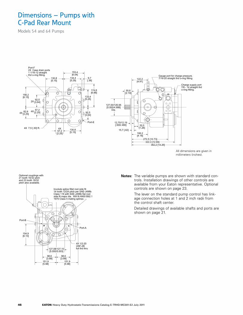
eaton Heavy Duty Hydrostatic Transmissions Catalog E-TRHD-MC001-E2 July 2011 46
Dimensions – Pumps with C-Pad Rear MountModels 54 and 64 Pumps
Notes: The variable pumps are shown with standard con-trols. Installation drawings of other controls are available from your Eaton representative. Optional controls are shown on page 23.
The lever on the standard pump control has link-age connection holes at 1 and 2 inch radii from the control shaft center.
Detailed drawings of available shafts and ports are shown on page 21.
Optional couplings with 21 tooth 16/32 pitch and 23 tooth 16/32 pitch also available.
Models 54 and 64 Pumps with C-Pad Rear Mount
4X57,2[2.25]
57,2[2.25]
4X 7,5 [.30] R.
82,6[3.25]
92,5[3.64]
Port-F2X Case drain ports1 1/16-12 straightthd o-ring fitting.
130,8[5.15]
156,2[6.15]
2X
174,8[6.88]
133,4[5.25]
153,4[6.04]
134,4[5.29]
9,7[.38]
Port-E
4X4X 92,5
[3.64]
130,8[5.15]
272,5 [10.73]322,3 [12.69]
106,2[4.18]
32,0[1.26]
122,2[4.91]
Gauge port for charge pressure.7/16-20 straight thd o-ring fitting.
15,7 [.62]
12,70/12,19[.500/.480]
127,00/126,95[5.000/4.998]
Dia.
55,6[2.19]
Charge supply port7/8 - 14 straight thdo-ring fitting.
362,2 [14.26]
A
B
127,08/127,10[5.000/5.003]
4X 1/2-20UNF-2Bfull thd thru
Involute spline fillet root side fit14 tooth 12/24 pitch per SAE-J498bClass 1 fit with SAE-J498b flat rootside fit major dia. Will fit ANSI B92.11970 Class 5 mating splines
151,9[5.98]
98,6[3.88]
98,6[3.88]
154,9[6.10]
151,9[5.98]
Port-A
Port-B
All dimensions are given in millimeters (inches).
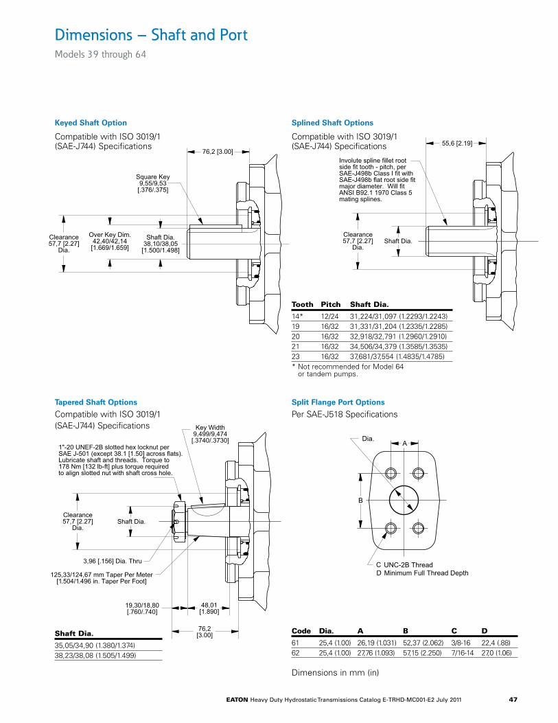
eaton Heavy Duty Hydrostatic Transmissions Catalog E-TRHD-MC001-E2 July 2011 47
Dimensions – Shaft and PortModels 39 through 64
76,2 [3.00]
Shaft Dia.38,10/38,05[1.500/1.498]
Over Key Dim.42,40/42,14[1.669/1.659]
Clearance57,7 [2.27]
Dia.
Square Key9,55/9,53[.376/.375]
Compatible with ISO 3019/1(SAE-J744) Specifications
Keyed Shaft Option
Keyed Shaft Option
Compatible with ISO 3019/1(SAE-J744) Specifications
Tapered Shaft Options
Compatible with ISO 3019/1(SAE-J744) Specifications
Splined Shaft Options
Compatible with ISO 3019/1(SAE-J744) Specifications
Clearance57,7 [2.27]
Dia.Shaft Dia.
55,6 [2.19]
Involute spline fillet rootside fit tooth - pitch, perSAE-J498b Class I fit withSAE-J498b flat root side fitmajor diameter. Will fitANSI B92.1 1970 Class 5mating splines.
Shaft Dia.Tooth Pitch14*
* Not recommended for Model 64 or tandem pumps.
19202123
12/2416/3216/3216/3216/32
31,224/31,097 [1.2293/1.2243]31,331/31,204 [1.2335/1.2285]32,918/32,791 [1.2960/1.2910]34,506/34,379 [1.3585/1.3535]37,681/37,554 [1.4835/1.4785]
Compatible with ISO 3019/1(SAE-J744) Specifications
Splined Shaft Options
tooth Pitch Shaft Dia.
14* 12/24 31,224/31,097 (1.2293/1.2243)19 16/32 31,331/31,204 (1.2335/1.2285)20 16/32 32,918/32,791 (1.2960/1.2910)21 16/32 34,506/34,379 (1.3585/1.3535)23 16/32 37,681/37,554 (1.4835/1.4785)* Not recommended for Model 64
or tandem pumps.
Shaft Dia.
35,05/34,90 (1.380/1.374)38,23/38,08 (1.505/1.499)
Clearance57,7 [2.27]
Dia.
48,01[1.890]
19,30/18,80[.760/.740]
76,2[3.00]
Shaft Dia.
125,33/124,67 mm Taper Per Meter[1.504/1.496 in. Taper Per Foot]
3,96 [.156] Dia. Thru
1"-20 UNEF-2B slotted hex locknut perSAE J-501 (except 38.1 [1.50] across flats).Lubricate shaft and threads. Torque to178 Nm [132 lb-ft] plus torque requiredto align slotted nut with shaft cross hole.
Key Width9,499/9,474[.3740/.3730]
Split Flange Port Options
Per SAE-J518 Specifications
A
B
C UNC-2B ThreadMinimum Full Thread DepthD
Dia.
Split Flange Port OptionsPer SAE-J518 Specifications
Code Dia. A B C25,4 [1.00]25,4 [1.00]
6162
26,19 [1.031]27,76 [1.093]
52,37 [2.062]57,15 [2.250]
3/8-167/16-14
22,4 [.88]27,0 [1.06]
D
Code Dia. a B C D
61 25,4 (1.00) 26,19 (1.031) 52,37 (2.062) 3/8-16 22,4 (.88)62 25,4 (1.00) 27,76 (1.093) 57,15 (2.250) 7/16-14 27,0 (1.06)
Dimensions in mm (in)
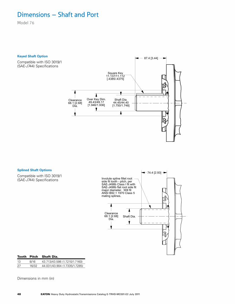
eaton Heavy Duty Hydrostatic Transmissions Catalog E-TRHD-MC001-E2 July 2011 48
Dimensions – Shaft and PortModel 76
Keyed Shaft Option
Compatible with ISO 3019/1(SAE-J744) Specifications
Splined Shaft Options
Compatible with ISO 3019/1(SAE-J744) Specifications
Clearance68.1 [2.68]
Dia.
Shaft Dia.44.45/44.40[1.750/1.748]
Over Key Dim.49.43/49.17
[1.946/1.936]
87.4 [3.44]
Square Key11.137/11.112[.4385/.4375]
Keyed Shaft OptionCompatible with ISO 3019/1(SAE-J744) Specifications
Clearance68.1 [2.68]
Dia.
Involute spline fillet rootside fit tooth - pitch, perSAE-J498b Class I fit withSAE-J498b flat root side fitmajor diameter. Will fitANSI B92.1 1970 Class 5mating splines.
Shaft Dia.
74.4 [2.93]
Shaft Dia.Tooth Pitch1327
8/1616/32
43.713/43.586 [1.7210/1.7160]44.031/43.904 [1.7335/1.7285]
Splined Shaft OptionsCompatible with ISO 3019/1(SAE-J744) Specifications
tooth Pitch Shaft Dia.
13 8/16 43.713/43.586 (1.7210/1.7160)27 16/32 44.031/43.904 (1.7335/1.7285)
Dimensions in mm (in)
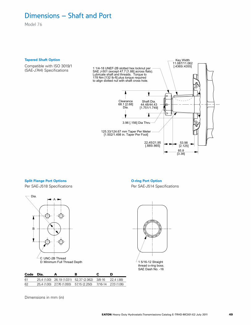
eaton Heavy Duty Hydrostatic Transmissions Catalog E-TRHD-MC001-E2 July 2011 49
Dimensions – Shaft and PortModel 76
Tapered Shaft Option
Compatible with ISO 3019/1(SAE-J744) Specifications
Split Flange Port Options
Per SAE-J518 SpecificationsO-ring Port Option
Per SAE-J514 Specifications
Dimensions in mm (in)
Clearance68.1 [2.68]
Dia.
125.33/124.67 mm Taper Per Meter[1.502/1.498 in. Taper Per Foot]
Shaft Dia.44.48/44.43[1.751/1.749]
1 1/4-18 UNEF-2B slotted hex locknut perSAE J-501 (except 47.7 [1.88] across flats).Lubricate shaft and threads. Torque to178 Nm [132 lb-ft] plus torque requiredto align slotted nut with shaft cross hole.
3.96 [.156] Dia Thru
85.8[3.38]
53.98[2.125]
22,45/21,95[.885/.865]
Key Width11.087/11.062[.4365/.4355]
Tapered Shaft OptionCompatible with ISO 3019/1(SAE-J744) Specifications
A
B
Dia.
C UNC-2B ThreadMinimum Full Thread DepthD
Split Flange Port OptionsPer SAE-J518 Specifications
Code Dia. A B C25.4 [1.00]25.4 [1.00]
6162
26.19 [1.031]27.76 [1.093]
52.37 [2.062]57.15 [2.250]
3/8-167/16-14
22.4 [.88]27.0 [1.06]
D
1 5/16-12 Straightthread o-ring boss.SAE Dash No. -16
O-ring Port OptionPer SAE-J514 Specifications
Code Dia. a B C D
61 25,4 (1.00) 26,19 (1.031) 52,37 (2.062) 3/8-16 22,4 (.88)62 25,4 (1.00) 27,76 (1.093) 57,15 (2.250) 7/16-14 27,0 (1.06)
eaton Heavy Duty Hydrostatic Transmissions Catalog E-TRHD-MC001-E2 July 2011 50
Application Information
Component DescriptionsThe Operational Diagram on page 46 shows a typical heavy duty hydrostatic transmission. The axial piston pump and axial piston motor are the main components. The filter, reservoir, heat exchanger, and oil lines make up the rest of the system. The function of each of these components is described below:
A separate energy source, such as an electric motor or internal combustion engine, turns the input shaft of the pump.
Variable Displacement Axial Piston PumpThe variable displacement pump provides a flow of high pressure oil. Pump output flow can be varied to obtain the desired motor output speed. For example, when the pump’s displacement is zero, no oil is pumped and the transmission’s motor output shaft is stopped. Conversely, maximum pump displacement produces maximum motor shaft speed. The direction of high pressure flow can also be reversed; doing so reverses the direction the motor output shaft rotates.
A charge pump is integrated into the piston pump and driven by the shaft of the piston pump. The drawing illustrates a suction filtration circuit. Eaton recommends a suction filter without a bypass valve. The charge pump has a Low Pressure Relief Valve that regulates the output pressure.
Power limiter valves and high pressure relief valves are available as options.
Fixed Displacement Axial Piston MotorThe motor uses the high pressure oil flow from the pump to produce transmission output. The high pressure oil comes to the motor through one of the high pressure lines. It enters the motor, turns the output shaft, then returns to the pump. Eaton piston motors integrate a hot oil shuttle and low pressure relief valve into the end cover. The shuttle valve and low pressure relief valve direct excess charge pump flow into the motor case. The shuttle valve is activated by high pressure and directs excess charge pump flow over the low pressure relief valve. This flushing action allows the charge pump to provide clean, cool oil to the closed loop circuit.
ReservoirThe reservoir is an important part of the hydrostatic transmission system. It should provide adequate oil storage and allow easy oil maintenance.
The reservoir must hold enough oil to provide a continuous oil supply to the charge pump inlet. It must also have enough room for the hydraulic oil to expand as the system warms up. Consider charge pump flow when sizing the reservoir: One half (.5) minute times (X) the maximum charge pump flow should be the minimum oil volume in
the reservoir. Maintaining this oil volume will give the oil a minimum of thirty (30) seconds in the reservoir. This will allow any entrained air to escape and contamination to settle out of the oil.
To allow for oil expansion, the reservoir’s total volume should be at least six tenths (.6) minute times (X) the maximum charge pump flow.
The reservoir’s internal structure should cut down turbulence and prevent oil aeration.
The line returning flow to the reservoir should be fitted with a diffuser to slow the incoming oil to 1 to 1.2 meters (3-4 feet) per second to help reduce turbulence. The return flow line should also be positioned so that returning oil enters the reservoir below the liquid surface. This will help reduce aeration and foaming of the oil.
The reservoir should have baffles between the return line and suction line. Baffles prevent return flow from immediately reentering the pump.
A sixty mesh screen placed across the suction chamber of the reservoir will act as a bubble separator. The screen should be placed at a thirty degree angle to the horizon.
The entrance to the suction line should be located well below the fluid surface so there is no chance of air being sucked into the charge pump inlet. However, the suction line entrance should not be located on the bottom of the reservoir where there may be a buildup of sediment. The suction line entrance should be flared and covered with a screen.
The reservoir should be easily accessible. The fill port should be designed to minimize the possibility of contamination during filling and to help prevent over filling. There should be a drain plug at the lowest point of the reservoir and it should also have a clean-out and inspection cover so the reservoir can be thoroughly cleaned after prolonged use. A vented reservoir should have a breather cap with a micronic filter.
Sealed reservoirs must be used at altitudes above 2500 feet. These reservoirs should be fitted with a two way micronic filter pressure cap to allow for fluid expansion and contraction.
In both cases the caps must be designed to prevent water from entering the reservoir during bad weather or machine washing.
A hydrostatic transmission with a well designed reservoir will run quieter, stay cleaner and last longer.
eaton Heavy Duty Hydrostatic Transmissions Catalog E-TRHD-MC001-E2 July 2011 51
Application Information
FilterA filter must be used to keep the hydraulic fluid clean. Either a suction filter or a pressure side filter may be used. The filter must be a no-bypass type. A suction filter is shown in the operational diagram on page 46 System oil particulate levels should not exceed ISO 18/13. Refer to Eaton Hydraulic Fluid Recommendations on page 54.
Recommended beta ratios for each filter type are listed below:
Suction Filter ß10 = 1.5 to 2.0
Pressure Side Filter ß10 = 10 to 20
When a suction filter is used, its flow capacity must be large enough to prevent an excessive pressure drop between the reservoir and charge pump inlet. The pressure at the charge pump inlet port must not be less than 0.8 bar (11.6 psi) absolute at normal continuous operating temperatures.
Charge Pump Inlet Line The inlet line to the charge pump should be large enough to keep the pressure drop between the reservoir and charge pump inlet within the limits described in the filter section. Fittings will increase the pressure drop, so their number should be kept to a minimum. It is best to keep fluid velocities below 1,25 meters (4 feet) per second.
Fluid and temperature compatibility must be considered when selecting the inlet line.
Pump and Motor Case Drain Lines The case drain lines should be large enough to limit the pump and motor case pressures to 2,8 bar (40 psi) at normal operating temperatures. Fluid and temperature compatibility must also be considered when selecting the case drain lines.
High Pressure Lines The high pressure lines that connect the pump and motor must be able to withstand the pressures generated in the high pressure loop.
Heat Exchanger Use of a heat exchanger is dependent on the transmis-sion’s duty cycle and on machine layout. The normal continuous operating fluid temperature measured in the pump and motor cases should not exceed 80°C (180°F) for most hydraulic fluids. The maximum fluid temperature should not exceed 105°C (220°F).
The heat exchanger should be sized to dissipate 25% of the maximum input power available to the transmission. It must also be sized to prevent the case pressures in the pump and motor from getting too high. Case pressure up to 2.8 bar (40 psi), at normal operating temperatures, are acceptable.
Heat Exchanger Bypass Valve The heat exchanger bypass valve is a pressure and/or temperature valve in parallel with the heat exchanger. Its purpose is to prevent case pressures from getting too high. The heat exchanger bypass valve opens when the oil is thick, especially during cold starts.
Reservoir Return Line The same general requirements that apply to case drain lines apply to the reservoir return line.
eaton Heavy Duty Hydrostatic Transmissions Catalog E-TRHD-MC001-E2 July 2011 52
Application Information
Shaft Couplings and Mounting Brackets Shaft couplings must be able to with stand the torque that will be transmitted to the pump or motor. If the pump or motor is to be directly coupled to the drive, the misalignment should not exceed .050 mm (.002 in.) total indicator run-out for the combination of perpen-dicularity and concentricity measurements.
The hardness of the couplings connected to Eaton pump or motor shafts should be 35 Rc for tapered or straight keyed shafts and 50-55 Rc for splined shafts.
Open Loop Circuits Eaton heavy duty pumps and heavy duty motors may be used in open loop circuits under certain operating conditions. Consult your Eaton repre-sentative for details.
Orientation The mounting orientation of Eaton heavy duty pumps and motors is unrestricted. The case drain line that carries the flow leaving the pump or motor should be connected to the highest drain port on each of the units. This assures that the pump and motor cases remain full.
Multiple Pump or Motor Circuits Multiple pumps or motors can be combined in the same circuit. When two pumps are used in a parallel circuit, their swashplate controls can be operated in phase or in sequence. The following precautions should be observed whenever multiple pumps and/or motors are connected in the same circuit:
1. Charge pump flow must be greater than the sum of the charge pump flow requirements of the individual units.
2. The possibility of motor overspeeding increases in multiple motor circuits. The parallel motor circuit will act as a frictionless differential. Should one of the motors stall the other could overspeed. The motors used in parallel circuits should, therefore, be sized to prevent overspeeding. Valves that will limit the flow to each of the motors may be used to prevent overspeeding. This will allow the use of smaller motors, however the flow limiting valves will create heat.
3. When using one pump with multiple motors, the case drain lines should be connected in series. The case flow should be routed from the most distant motor, through the remaining motors, to the pump, and finally back to the reservoir. The
most distant motor should have the valve block or integral shuttle valve while the additional motors do not need a valve block or integral shuttle valve. A remote valve block is also available for multiple motor circuits. A series-parallel drain line circuit may be needed for the high case flow created in multiple pump circuits. In either case, each pump and motor should be checked for proper cooling when testing the prototype circuit.
4. Series circuits present a unique problem for axial piston motors. Pressure applied to the input port and discharge port are additive as regards to the load and life of the drive shaft and the drive shaft bearings. Please consult with your Eaton repre-sentative regarding series circuits.
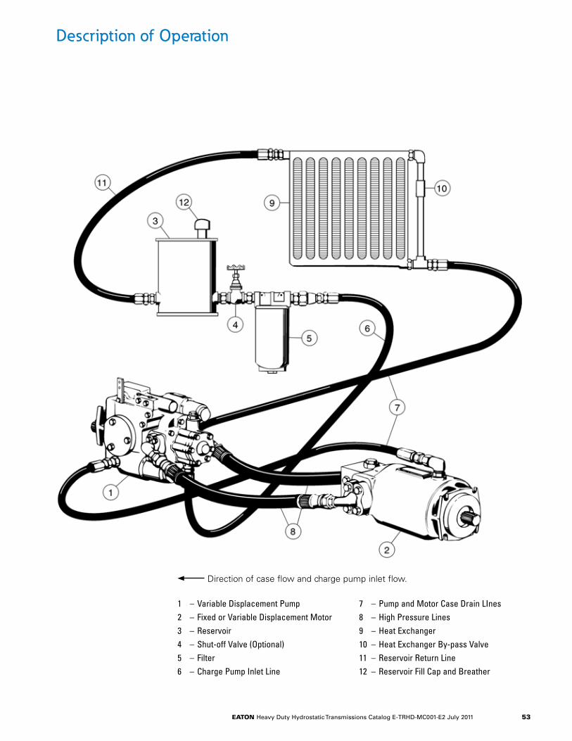
eaton Heavy Duty Hydrostatic Transmissions Catalog E-TRHD-MC001-E2 July 2011 53
Description of Operation
1 – Variable Displacement Pump2 – Fixed or Variable Displacement Motor3 – Reservoir4 – Shut-off Valve (Optional)5 – Filter6 – Charge Pump Inlet Line
7 – Pump and Motor Case Drain LInes8 – High Pressure Lines9 – Heat Exchanger10 – Heat Exchanger By-pass Valve11 – Reservoir Return Line12 – Reservoir Fill Cap and Breather
Direction of case flow and charge pump inlet flow.
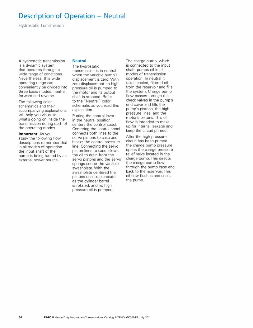
eaton Heavy Duty Hydrostatic Transmissions Catalog E-TRHD-MC001-E2 July 2011 54
A hydrostatic transmission is a dynamic system that operates through a wide range of conditions. Nevertheless, this wide operating range can conveniently be divided into three basic modes: neutral, forward and reverse.
The following color schematics and their accompanying explanations will help you visualize what’s going on inside the transmission during each of the operating modes.
Important: As you study the following flow descriptions remember that in all modes of operation the input shaft of the pump is being turned by an external power source.
Neutral The hydrostatic transmission is in neutral when the variable pump’s displacement is zero. With zero displacement no high pressure oil is pumped to the motor and its output shaft is stopped. Refer to the “Neutral” color schematic as you read this explanation.
Putting the control lever in the neutral position centers the control spool. Centering the control spool connects both lines to the serve pistons to case and blocks the control pressure line. Connecting the servo piston lines to case allows the oil to drain from the servo pistons and the servo springs center the variable swashplate. With the swashplate centered the pistons don’t reciprocate as the cylinder barrel is rotated, and no high pressure oil is pumped.
The charge pump, which is connected to the input shaft, pumps oil in all modes of transmission operation. In neutral it takes cooled, filtered oil from the reservoir and fills the system. Charge pump flow passes through the check valves in the pump’s end cover and fills the pump’s pistons, the high pressure lines, and the motor’s pistons. This oil flow is intended to make up for internal leakage and keep the circuit primed.
After the high pressure circuit has been primed the charge pump pressure opens the charge pressure relief valve located in the charge pump. This directs the charge pump flow through the pump case and back to the reservoir. This oil flow flushes and cools the pump.
Description of Operation – NeutralHydrostatic Transmission
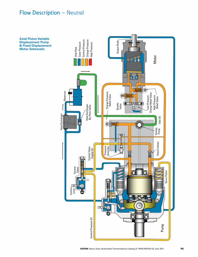
eaton Heavy Duty Hydrostatic Transmissions Catalog E-TRHD-MC001-E2 July 2011 55
Char
gePu
mp
Inle
t Oil
Chec
k Va
lves
Shut
tleVa
lve
Low
Pre
ssur
eCh
arge
Rel
ief V
alve
High
Pre
ssur
eRe
lief V
alve
Char
ge P
ress
ure
Relie
f Val
ve
Heat
Exc
hang
er
Heat
Exc
hang
erBy
-Pas
s Va
lve
Cont
rol
Leve
rCo
ntro
l Va
lve
Cont
rol V
alve
Supp
ly O
ilCo
ntro
l Pre
ssur
e Oi
l
Serv
o Pi
ston
Mot
or
Pum
p
Inle
t Flo
wCa
se P
ress
ure
Cont
rol P
ress
ure
Char
ge P
ress
ure
High
Pre
ssur
e
Rese
rvoi
r
Outp
ut S
haft
Pres
sure
Ov
errid
e
Flow Description – Neutral
Axial Piston Variable Displacement Pump & Fixed Displacement Motor Schematic
eaton Heavy Duty Hydrostatic Transmissions Catalog E-TRHD-MC001-E2 July 2011 56
Description of Operation – Forward/ReverseHydrostatic Transmission
The forward mode and the reverse mode are similar, so hence forth they will be grouped and called the forward/reverse mode.
Forward/Reverse The hydrostatic transmission is in forward/reverse mode when flow in the high pressure circuit causes the motor shaft to rotate. Refer to the forward/reverse color schematic as you can read this explanation.
Flow in the high pressure circuit is created by tilting the pump’s variable swashplate from its center, or neutral, position. With the swashplate tilted the pistons reciprocate as the cylinder barrel rotates and flow is generated.
The swashplate may be tilted to either side of center. Tilting it one way generates flow that makes the transmission go forward. And tilting it the other way reverses flow and the motor shaft rotates in the opposite direction.
Besides controlling direction, the swashplate angle also controls output speed. Swashplate angle affects speed by changing the pump’s displacement. The largest swashplate angle produces the largest displacement and the fastest motor speed.
The standard control circuit has a single lever that sets both speed and direction. Center the lever for neutral. Move it to one side of center for forward, the other side for reverse. Motor speed is controlled by how far the lever is moved.
The control circuit varies the swashplate angle by directing control pressure to either of the servo pistons. Control pressure, at the charge pressure relief valve setting, is supplied to the control valve by the charge pump. In the forward/reverse schematic control pressure is directed to the lower servo piston which causes the swashplate to tilt. Oil in the upper servo sleeve drains to case, through the control valve, as the swashplate tilts.
The follow-up link, between the swashplate and control valve, holds the swashplate at the angle set by the control lever. As the swashplate moves to the desired angle the follow-up link moves the control spool so that it opens/closes the lines to the servo pistons. The swashplate will hold that position until the control lever is moved.
Charge pump flow that is not used by the control circuit passes through the end cover check valve into the low pressure side of the loop. There it provides back pressure to the motor pistons.
The spring centered shuttle valve, located in the motor’s valve block, moves to connect the low pressure side of the loop to the charge pressure relief valve. When back pressure gets high enough the charge pressure relief valve, in the valve block, opens and charge pump flow enters the motor case.
Case flow flushes the pump and motor cases and helps keep the transmission cool. The charge pressure relief valve in the motor’s valve block typically has a lower setting than the charge pressure relief valve in the charge pump. This is so case flow will begin at the motor, go to the pump, and return to the reservoir. The arrows on the drawing a A Typical Heavy Duty Hydrostatic Transmission, page 4, show case flow’s path.
The charge pressure relief valve in the charge pump opens when the transmission is in neutral and the shuttle valve is centered. Compare the shuttle valve in each of the color schematics to better understand its operation.
The high pressure relief valves in the motor’s valve block open to connect the high pressure side of the loop to the low pressure side if the motor stalls and the pressure gets too high. There are two high pressure relief valves; one works in forward the other in reverse.
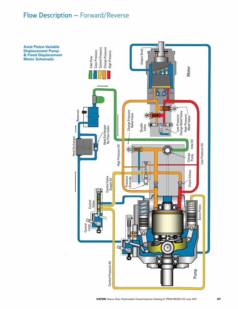
eaton Heavy Duty Hydrostatic Transmissions Catalog E-TRHD-MC001-E2 July 2011 57
Flow Description – Forward/Reverse
Axial Piston Variable Displacement Pump & Fixed Displacement Motor Schematic
Char
gePu
mp
Inle
t Oil
Chec
k Va
lves
Shut
tleVa
lve
Low
Pre
ssur
eCh
arge
Rel
ief V
alve
High
Pre
ssur
eRe
lief V
alve
Char
ge P
ress
ure
Relie
f Val
ve
Heat
Exc
hang
er
Heat
Exc
hang
erBy
-Pas
s Va
lve
Cont
rol
Leve
rCo
ntro
l Va
lve
Cont
rol V
alve
Supp
ly O
il
High
Pre
ssur
e Oi
l
Pres
sure
Ov
errid
e
Low
Pre
ssur
e Oi
l
Cont
rol P
ress
ure
Oil
Serv
o Pi
ston
Mot
orPu
mp
Outp
ut S
haft
Inle
t Flo
wCa
se P
ress
ure
Cont
rol P
ress
ure
Char
ge P
ress
ure
High
Pre
ssur
e
Rese
rvoi
r
eaton Heavy Duty Hydrostatic Transmissions Catalog E-TRHD-MC001-E2 July 2011 58
Hydraulic Fluid Recommendations
ObjectiveThe ability of Eaton hydrostatic components to provide the desired performance and life expectancy depends largely on the fluid used. The purpose of this document is to provide readers with the knowledge required to select the appropriate fluids for use in systems that employ Eaton hydrostatic components.
Selecting a Hydraulic FluidThe hydraulic fluids in hydraulic systems are bound to perform in different dimensions. They serve as the power transmission medium, lubricate the moving components and carry away the heat produced within the system. Therefore the fluids must have adequate properties to give the assurance of adequate wear protection, effective power transmission and excellent chemical stability under the most adverse operating conditions. The multi dimensional performance establishes that the hydraulic fluid is a vital factor in a hydraulic system; proper selection of oil assures satisfactory life and operation of the system components / lubricants.
ViscosityThe most important charac-teristics to consider when choosing a fluid to be used in a hydraulic system are viscosity. The fluid must be thin enough to flow easily but thick enough to seal and maintain a lubricating film between bearing and sealing surfaces. Viscosity requirements for Eaton’s Heavy Duty Hydrostatic product line are specified later in this document
Viscosity and TemperatureTemperature and viscosity are related inversely. As the fluid warms it gets thinner and its viscosity decreases. When fluid cools the fluid viscosity increases. It is important to consider the entire operating temperature window for selecting the right viscosity for a hydraulic system. Calculate the viscosity of the fluid temperatures at start up, normal operating conditions and maximum possible point, and compare the same with the recommendation of the hydraulic system.
Generally, the fluid is thick when the hydraulic system is started. With movement, the fluid warms to a point where the cooling system begins to operate. From then on, the fluid is maintained at the temperature for which the hydrostatic system was designed. In actual applications this sequence varies; hydrostatic systems are used in many environments from very cold to very hot. Cooling systems also vary from very elaborate to very simple, so ambient temperature may affect operating temperature. Equipment manufac-turers who use Eaton hydrostatic components in their products should anticipate temperature in their designs and make the appropriate fluid rec-ommendations to their customers.
In general, a lower ISO viscosity grade fluid is recommended for operation in cold to moderate climates. Higher ISO viscosity grade fluid is recommended for operation in moderate to hot climates.
CleanlinessCleanliness of the fluid in a hydrostatic system is extremely important. Eaton recommends that the fluid used in its hydrostatic components be maintained at ISO Cleanliness Code 18/13 per SAE J1165. This code allows a maximum of 2500 particles per milliliter greater than 5 µm and a maximum of 80 particles per milliliter greater than 15 µm. When components with different cleanliness requirements are used in the same system, the cleanest standard should be applied. OEM’s and distributors who use Eaton hydrostatic components in their products should provide for these requirements in their designs. A reputable filter supplier can supply filter information.
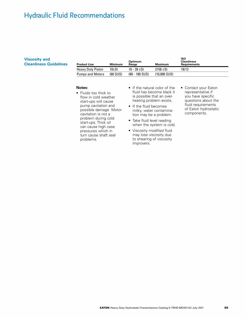
eaton Heavy Duty Hydrostatic Transmissions Catalog E-TRHD-MC001-E2 July 2011 59
Hydraulic Fluid Recommendations
Viscosity and Cleanliness Guidelines
ISO Optimum Cleanliness Product Line Minimum Range Maximum Requirements
Heavy Duty Piston 10cSt 16 - 39 cSt 2158 cSt 18/13Pumps and Motors (60 SUS) (80 - 180 SUS) (10,000 SUS)
Notes: • Fluids too thick to
flow in cold weather start-ups will cause pump cavitation and possible damage. Motor cavitation is not a problem during cold start-ups. Thick oil can cause high case pressures which in turn cause shaft seal problems.
• If the natural color of the fluid has become black it is possible that an over-heating problem exists.
• If the fluid becomes milky, water contamina-tion may be a problem.
• Take fluid level reading when the system is cold.
• Viscosity modified fluid may lose viscosity due to shearing of viscosity improvers.
• Contact your Eaton representative if you have specific questions about the fluid requirements of Eaton hydrostatic components.
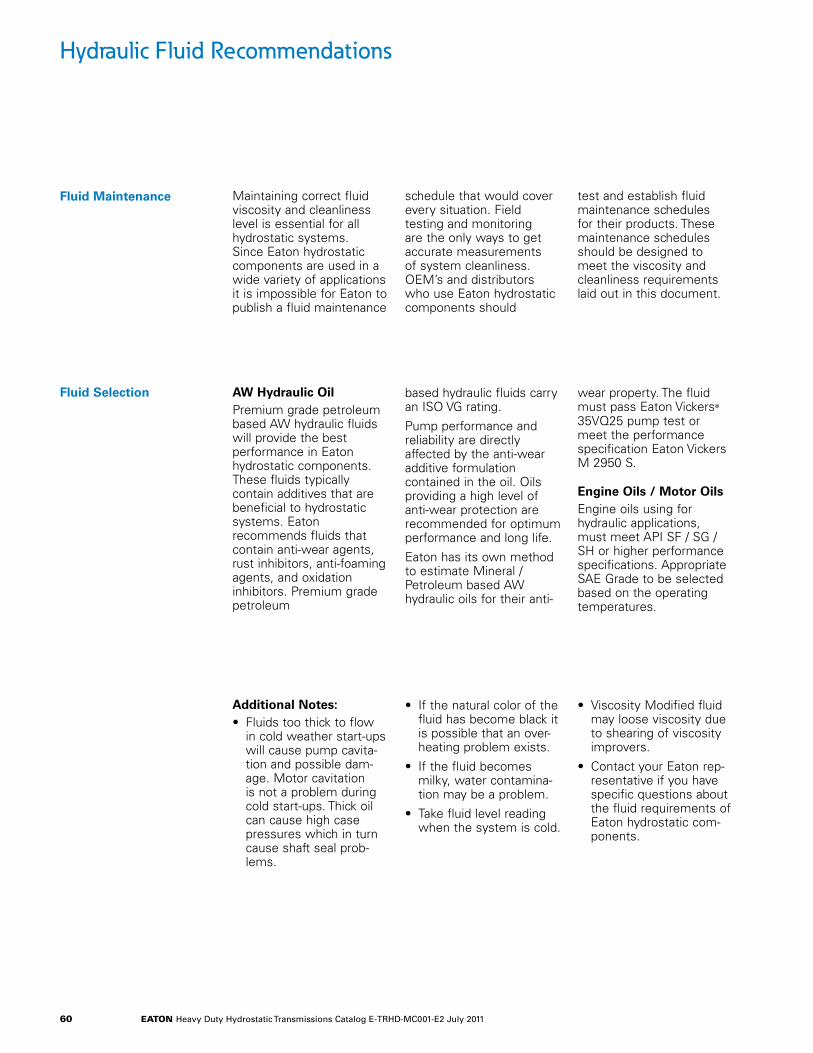
eaton Heavy Duty Hydrostatic Transmissions Catalog E-TRHD-MC001-E2 July 2011 60
Maintaining correct fluid viscosity and cleanliness level is essential for all hydrostatic systems. Since Eaton hydrostatic components are used in a wide variety of applications it is impossible for Eaton to publish a fluid maintenance
schedule that would cover every situation. Field testing and monitoring are the only ways to get accurate measurements of system cleanliness. OEM’s and distributors who use Eaton hydrostatic components should
test and establish fluid maintenance schedules for their products. These maintenance schedules should be designed to meet the viscosity and cleanliness requirements laid out in this document.
Additional Notes:• Fluids too thick to flow
in cold weather start-ups will cause pump cavita-tion and possible dam-age. Motor cavitation is not a problem during cold start-ups. Thick oil can cause high case pressures which in turn cause shaft seal prob-lems.
• If the natural color of the fluid has become black it is possible that an over-heating problem exists.
• If the fluid becomes milky, water contamina-tion may be a problem.
• Take fluid level reading when the system is cold.
• Viscosity Modified fluid may loose viscosity due to shearing of viscosity improvers.
• Contact your Eaton rep-resentative if you have specific questions about the fluid requirements of Eaton hydrostatic com-ponents.
Fluid Maintenance
AW Hydraulic OilPremium grade petroleum based AW hydraulic fluids will provide the best performance in Eaton hydrostatic components. These fluids typically contain additives that are beneficial to hydrostatic systems. Eaton recommends fluids that contain anti-wear agents, rust inhibitors, anti-foaming agents, and oxidation inhibitors. Premium grade petroleum
based hydraulic fluids carry an ISO VG rating.
Pump performance and reliability are directly affected by the anti-wear additive formulation contained in the oil. Oils providing a high level of anti-wear protection are recommended for optimum performance and long life.
Eaton has its own method to estimate Mineral / Petroleum based AW hydraulic oils for their anti-
wear property. The fluid must pass Eaton Vickers@ 35VQ25 pump test or meet the performance specification Eaton Vickers M 2950 S.
Engine Oils / Motor OilsEngine oils using for hydraulic applications, must meet API SF / SG / SH or higher performance specifications. Appropriate SAE Grade to be selected based on the operating temperatures.
Fluid Selection
Hydraulic Fluid Recommendations
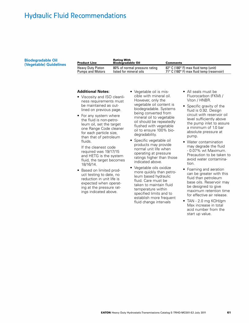
eaton Heavy Duty Hydrostatic Transmissions Catalog E-TRHD-MC001-E2 July 2011 61
Biodegradable Oil (Vegetable) Guidelines
Rating With Product Line Biodegradable oil Comments
Heavy Duty Piston 80% of normal pressure rating 82° C (180° F) max fluid temp (unit) Pumps and Motors listed for mineral oils 71° C (160° F) max fluid temp (reservoir)
Additional Notes:• Viscosity and ISO cleanli-
ness requirements must be maintained as out-lined on previous page.
• For any system where the fluid is non-petro-leum oil, set the target one Range Code cleaner for each particle size, than that of petroleum fluids.
If the cleanest code required was 19/17/15 and HETG is the system fluid, the target becomes 18/16/14.
• Based on limited prod-uct testing to date, no reduction in unit life is expected when operat-ing at the pressure rat-ings indicated above.
• Vegetable oil is mis-cible with mineral oil. However, only the vegetable oil content is biodegradable. Systems being converted from mineral oil to vegetable oil should be repeatedly flushed with vegetable oil to ensure 100% bio-degradability.
• Specific vegetable oil products may provide normal unit life when operating at pressure ratings higher than those indicated above.
• Vegetable oils oxidize more quickly than petro-leum based hydraulic fluid. Care must be taken to maintain fluid temperature within specified limits and to establish more frequent fluid change intervals
• All seals must be Fluorocarbon (FKM) / Viton / HNBR.
• Specific gravity of the fluid is 0.92. Design circuit with reservoir oil level sufficiently above the pump inlet to assure a minimum of 1.0 bar absolute pressure at pump.
• Water contamination may degrade the fluid - 0.07% wt Maximum. Precaution to be taken to avoid water contamina-tion.
• Foaming and aeration can be greater with this fluid than petroleum base oils. Reservoir may be designed to give maximum retention time for effective air release.
• TAN - 2.0 mg KOH/gm Max increase in total acid number from the start up value.
Hydraulic Fluid Recommendations

eaton Heavy Duty Hydrostatic Transmissions Catalog E-TRHD-MC001-E2 July 2011 62
Notes
EatonHydraulics Group USA14615 Lone Oak RoadEden Prairie, MN 55344USATel: 952-937-9800Fax: 952-294-7722www.eaton.com/hydraulics
EatonHydraulics Group EuropeRoute de la Longeraie 71110 MorgesSwitzerlandTel: +41 (0) 21 811 4600Fax: +41 (0) 21 811 4601
Eaton Hydraulics Group Asia PacificEaton Building4th Floor, No. 3 Lane 280 Linhong Rd. Changning DistrictShanghai 200335ChinaTel: (+86 21) 5200 0099Fax: (+86 21) 5200 0400
© 2011 Eaton CorporationAll Rights ReservedPrinted in USADocument No. E-TRHD-MC001-E2Supersedes E-TRHD-MC001-E1July 2011