series 2, 3, 4, & 5 aluminum - accessories 2, 3, 4, & 5 aluminum green= fastest shipped...
TRANSCRIPT
Series 2, 3, 4, &
5 Alum
inum
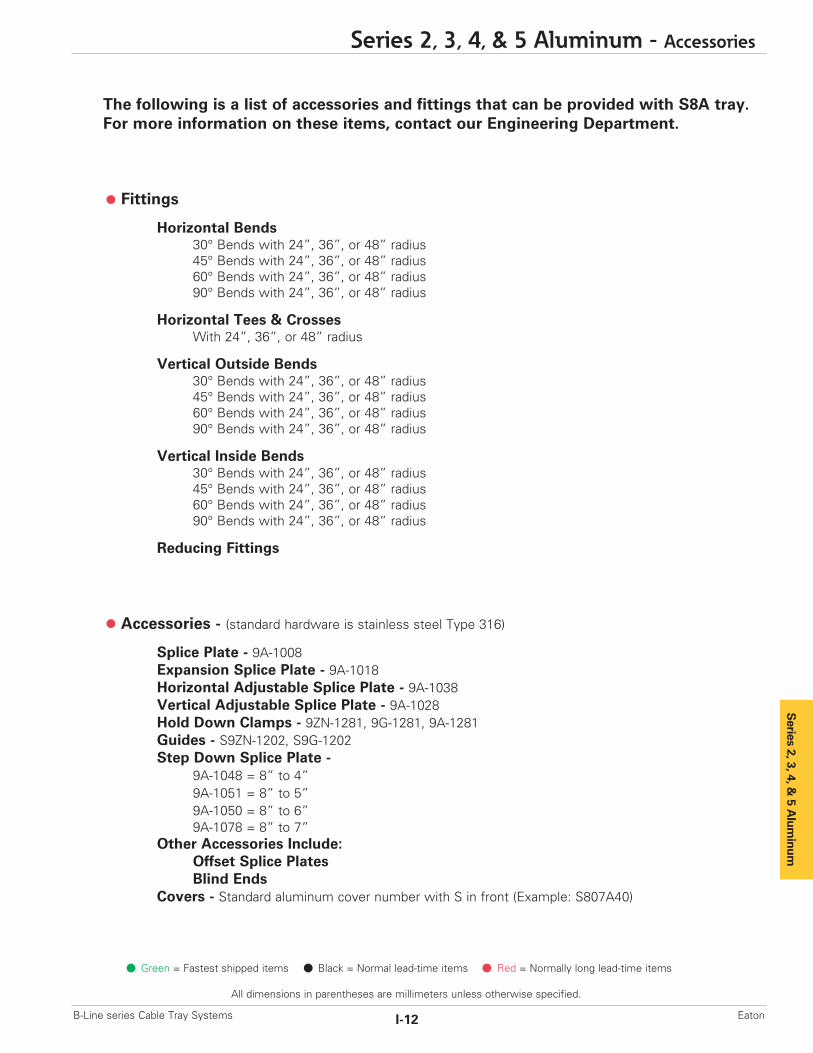
The following is a list of accessories and fittings that can be provided with S8A tray.For more information on these items, contact our Engineering Department.
Fittings
Horizontal Bends30° Bends with 24”, 36”, or 48” radius45° Bends with 24”, 36”, or 48” radius60° Bends with 24”, 36”, or 48” radius90° Bends with 24”, 36”, or 48” radius
Horizontal Tees & CrossesWith 24”, 36”, or 48” radius
Vertical Outside Bends30° Bends with 24”, 36”, or 48” radius45° Bends with 24”, 36”, or 48” radius60° Bends with 24”, 36”, or 48” radius90° Bends with 24”, 36”, or 48” radius
Vertical Inside Bends30° Bends with 24”, 36”, or 48” radius45° Bends with 24”, 36”, or 48” radius60° Bends with 24”, 36”, or 48” radius90° Bends with 24”, 36”, or 48” radius
Reducing Fittings
Accessories - (standard hardware is stainless steel Type 316)
Splice Plate - 9A-1008Expansion Splice Plate - 9A-1018Horizontal Adjustable Splice Plate - 9A-1038Vertical Adjustable Splice Plate - 9A-1028Hold Down Clamps - 9ZN-1281, 9G-1281, 9A-1281Guides - S9ZN-1202, S9G-1202Step Down Splice Plate -
9A-1048 = 8” to 4”9A-1051 = 8” to 5”9A-1050 = 8” to 6”9A-1078 = 8” to 7”
Other Accessories Include:Offset Splice PlatesBlind Ends
Covers - Standard aluminum cover number with S in front (Example: S807A40)
Green = Fastest shipped items Black = Normal lead-time items Red = Normally long lead-time items
Series 2, 3, 4, & 5 Aluminum - Accessories
I-12B-Line series Cable Tray Systems Eaton
All dimensions in parentheses are millimeters unless otherwise specified.

Catalog No. Heightin. mm
9A-1004 4 (101)9A-1005 5 (127)9A-1006 6 (152)9A-1007 7 (178)
Series 2, 3, 4, & 5 Aluminum
Catalog No. Heightin. mm
9A-1014 4 (101)9A-1015 5 (127)9A-1016 6 (152)9A-1017 7 (178)
Catalog No. Heightin. mm
9A-1004-1/2 4 (101)9A-1005-1/2 5 (127)9A-1006-1/2 6 (152)9A-1007-1/2 7 (178)
Catalog No. Heightin. mm
9A-1045 5 to 4 (127 to 101)9A-1046 6 to 4 (152 to 101)9A-1060 6 to 5 (152 to 127)9A-1047 7 to 4 (178 to 101)9A-1061 7 to 5 (178 to 127)9A-1062 7 to 6 (178 to 152)
Catalog No. Heightin. mm
9A-1024 4 (101)9A-1025 5 (127)9A-1026 6 (152)9A-1027 7 (178)
Catalog No. TraySeries
9A-6006 H46A9A-6007 H47A, 57A
Requires supports within 24” onboth sides, per NEMA VE 2.
Green = Fastest shipped items Black = Normal lead-time items Red = Normally long lead-time items
All dimensions in parentheses are millimeters unless otherwise specified.
Series 2, 3, 4, & 5 Aluminum - Accessories
I-13 B-Line series Cable Tray SystemsEaton
Wedge Lock Splice Plates
• Furnished in pairs with 1/4" hardware.• Standard 4-hole pattern.• Furnished in pairs, with hardware.• One pair including hardware provided with each section.(Expansion splice quantity subtracted)
• Boxed in pairs with hardware.• For field installation drill 13/32" hole.
Expansion Splice Plates
• Expansion plates allow for one inch expansion or contraction of the cable tray, or where expansion joints occur in thesupporting structure.
• Furnished in pairs with hardware.• Bonding Jumpers are required on each siderail.Order Separately.
For heavy duty expansion splice plates see page APP-3.
Universal Splice Plates
• Furnished in pairs with 1/4" hardware.• UL Classified.
Step Down Splice Plates
• These splice plates are offered for connecting cable tray sections having side rails of different heights.
• Furnished in pairs with hardware.
H46A, H47A and 57A Mid-Span Splice
• Furnished in pairs with 1/4" hardware.• Standard for H46A, H47A and 57A straight sections.• Six bolt design 1/2" Stainless Steel Type 316 hardware standard.
• Available on ladder bottoms only. 09 and 12" rung spacing.• Furnished in pairs with hardware.
Vertical Adjustable Splice Plates
• These plates provide for changes in elevation thatdo not conform to standard vertical fittings.
• Furnished in pairs with hardware.• Bonding Jumpers not required.

Series 2, 3, 4, &
5 Alum
inum
Green = Fastest shipped items Black = Normal lead-time items Red = Normally long lead-time items
Series 2, 3, 4, & 5 Aluminum - Accessories
I-14B-Line series Cable Tray Systems Eaton
All dimensions in parentheses are millimeters unless otherwise specified.
Offset Reducing Splice Plate
• This plate is used for joining cable trays having different widths.When used in pairs they form a straight reduction; when usedsingly with a standard splice plate, they form an offset reduction.
• Furnished as one plate with hardware.• (‡) Insert reduction
Frame Type Box Connector• Designed to attach the end of a cable tray run to a distributioncabinet or control center to help reinforce the box at thepoint of entry.
• Furnished with tray connection hardware.
Blind End• This plate forms a closure for a dead end cable tray.• Furnished as one plate with hardware.• (‡) Insert tray width
Tray to Box Splice Plates• Used to attach the end of a cable tray run to a distributionbox or control panel.
• Furnished in pairs with hardware
Horizontal Adjustable Splice Plates• Offered to adjust a cable tray run for changes indirection in a horizontal plane that do not conform to standard horizontal fittings.
• Furnished in pairs with hardware.• Bonding jumpers not required.• (X) Insert 4, 5, 6 or 7 for side rail height.
Branch Pivot Connectors• Branch from existing cable tray runs at any point.• Pivot to any required angle.• UL Classified for grounding (bonding jumpers not required).
• Furnished in pairs with hardware.
Catalog Cable Tray Thru Tray Width ‘L’No. End Cut in. (mm) in. (mm)
9A-103(X) Mitered 36 (914) N/A (NA)9A-103(X)-12 Not mitered 12 (305) 16 (406)9A-103(X)-36 Not mitered 36 (914) 41 (1041)
9A-103(X)Splice only
9A-103(X)-12 or 9A-103(X)-36One pair splice plates with extensions.
LL
Requires supports within 24” onboth sides, per NEMA VE 2.
Catalog No. Heightin. mm
9A-2044 4 (101)9A-2045 5 (127)9A-2046 6 (152)9A-2047 7 (178)
Catalog No. Heightin. mm
9A-1054 4 (101)9A-1055 5 (127)9A-1056 6 (152)9A-1057 7 (178)
Catalog No. Heightin. mm
9A-1064-(‡) 4 (101)9A-1065-(‡) 5 (127)9A-1066-(‡) 6 (152)9A-1067-(‡) 7 (178)
Catalog No. Heightin. mm
9A-1084-(‡) 4 (101)9A-1085-(‡) 5 (127)9A-1086-(‡) 6 (152)9A-1087-(‡) 7 (178)
Catalog No. Heightin. mm
9A-1074-(‡) 4 (101)9A-1075-(‡) 5 (127)9A-1076-(‡) 6 (152)9A-1077-(‡) 7 (178)

Series 2, 3, 4, & 5 Aluminum
All dimensions in parentheses are millimeters unless otherwise specified.
Series 2, 3, 4, & 5 Aluminum - Accessories
I-15 B-Line series Cable Tray SystemsEaton
Catalog No. Description
SNCB 3/8” x 3/4” ZN Square Neck Carriage Bolt ASTM A307 Grade A
SFHN 3/8”-16 ZN Serrated Flange Hex Nut ASTM A563 Grade A
Catalog No.
9A-1240
Catalog No.
9ZN-1150-(‡)
Catalog No.
9ZN-1155-(‡)
Catalog No.
99-2125-15
Catalog No. Conduit Sizein. mm
9G-1158-1/2, 3/2 1/2, 3/4 (15, 20)9G-1158-1, 11/4 1, 11/4 (25, 32)9G-1158-11/2, 2 11/2, 2 (40, 50)9G-1158-21/2, 3 21/2, 3 (65, 80)9G-1158-31/2, 4 31/2, 4 (90, 100)
Green = Fastest shipped items Black = Normal lead-time items Red = Normally long lead-time items
Standard Tray Hardware (for field installation drill 13/32” hole)
• Finish: Zinc Plated ASTM B633 SC1
Cross Connector Bracket
• For field connecting crossing section.• Furnished in pairs with 3/8" hardware.
Conduit to Cable Tray Adaptor
• For easy attachment of conduit terminatingat a cable tray.
• Use on aluminum or steel cable trays.
Conduit to Cable Tray Adaptor
• Assembly required.• Mounting hardware included.• Conduit clamps provided.• (‡) = Insert conduit size (1/2" thru 4").
Cable Tie (Ladder Tray)
• Nylon ties provide easy attachment of cable to ladder rungs; maximum cable O.D. is 3" (76mm).
Conduit to Cable Tray Adaptor
• Assembly required.• Conduit clamps included.• (‡) = Insert conduit size (1/2" thru 4").
Catalog No. Description
SNCB 3/8” x 3/4” SS6 Square Neck Carriage Bolt AISI 316 Stainless Steel
SFHN 3/8”-16 SS6 Serrated Flange Hex Nut AISI 316 Stainless Steel
Optional Tray Hardware (for field installation drill 13/32” hole)
• To order 316 stainless steel hardwareadd SS6 suffix to catalog number -Example: 9A1004SS6
AluminumI-Beam
Overall Length 15" (381mm)
Series 2, 3, 4, &
5 Alum
inum
Series 2, 3, 4, & 5 Aluminum - Accessories
I-16B-Line series Cable Tray Systems Eaton
All dimensions in parentheses are millimeters unless otherwise specified.
Green = Fastest shipped items Black = Normal lead-time items Red = Normally long lead-time items
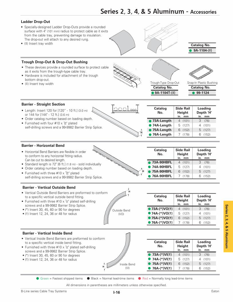
Barrier - Straight Section
• Length: Insert 120 for [120” - 10 ft.] (3.0 m)or 144 for [144" - 12 ft.] (3.6 m)
• Order catalog number based on loading depth.• Furnished with four #10 x 1/2" platedself-drilling screws and a 99-9982 Barrier Strip Splice.
Barrier - Vertical Outside Bend• Vertical Outside Bend Barriers are preformed to conformto a specific vertical outside bend fitting.
• Furnished with three #10 x 1/2" plated self-drilling screws and a 99-9982 Barrier Strip Splice.
• (*) Insert 30, 45, 60 or 90 for degrees• (†) Insert 12, 24, 36 or 48 for radius
Barrier - Vertical Inside Bend• Vertical Inside Bend Barriers are preformed to conformto a specific vertical inside bend fitting.
• Furnished with three #10 x 1/2" plated self-drilling screws and a 99-9982 Barrier Strip Splice.
• (*) Insert 30, 45, 60 or 90 for degrees• (†) Insert 12, 24, 36 or 48 for radius
Barrier - Horizontal Bend
• Horizontal Bend Barriers are flexible in order to conform to any horizontal fitting radius. Can be cut to desired length.
• Standard length is 72" [6 ft.] (1.8 m) - sold individually• Order catalog number based on loading depth.• Furnished with three #10 x 1/2" platedself-drilling screws and a 99-9982 Barrier Strip Splice.
Ladder Drop-Out• Specially-designed Ladder Drop-Outs provide a rounded surface with 4" (101 mm) radius to protect cable as it exits from the cable tray, preventing damage to insulation.The drop-out will attach to any desired rung.
• (‡) Insert tray width
Trough Drop-Out & Drop-Out Bushing• These devices provide a rounded surface to protect cableas it exits from the trough-type cable tray.
• Hardware is included for attachment of the troughbottom drop-out.
• (‡) Insert tray width Snap-In Plastic BushingTrough-Type Drop-Out
Catalog No.
9A-1104-(‡)
Catalog No.
99-1124
Catalog No.
9A-1104T-(‡)
Catalog Side Rail LoadingNo. Height Depth 'H'
in. mm in. mm
73A-Length 4 (101) 3 (76)74A-Length 5 (127) 4 (101)75A-Length 6 (152) 5 (127)76A-Length 7 (178) 6 (152)
H
H
Catalog Side Rail LoadingNo. Height Depth 'H'
in. mm in. mm
73A-90HBFL 4 (101) 3 (76)74A-90HBFL 5 (127) 4 (101)75A-90HBFL 6 (152) 5 (127)76A-90HBFL 7 (178) 6 (152)
Catalog Side Rail LoadingNo. Height Depth 'H'
in. mm in. mm
73A-(*)VO(†) 4 (101) 3 (76)74A-(*)VO(†) 5 (127) 4 (101)75A-(*)VO(†) 6 (152) 5 (127)76A-(*)VO(†) 7 (178) 6 (152)
Catalog Side Rail LoadingNo. Height Depth 'H'
in. mm in. mm
73A-(*)VI(†) 4 (101) 3 (76)74A-(*)VI(†) 5 (127) 4 (101)75A-(*)VI(†) 6 (152) 5 (127)76A-(*)VI(†) 7 (178) 6 (152)
Outside Bend(VO)
Inside Bend(VI)
H
H

Series 2, 3, 4, & 5 Aluminum
All dimensions in parentheses are millimeters unless otherwise specified.
Series 2, 3, 4, & 5 Aluminum - Accessories
I-17 B-Line series Cable Tray SystemsEaton
Screw slot forsheet metal screw
Rung
B655Rod Coupling
BarrierFlange
Catalog No.
99-9982
Green = Fastest shipped items Black = Normal lead-time items Red = Normally long lead-time items
Barrier Strip Clip
• Provides attachment to rung.• Allows for installed barrier adjustment.• Asymmetrical clip provides a wide range for screw location.• Barriers strip clips not included with barriers.(Must be ordered separately)
Barrier Strip Splice
• Plastic splice holds adjoining barrier strips in straight alignment.• 3” (76mm) long.
Bonding Jumper
Use at each expansion splice and where the cable tray is not mechanically/electrically continuous to ground. Sold individually.• Hardware included.• See table 392.6(B)(2) on page CTS-9 for amperage ratingsrequired to match the UL cross-sectional area of the tray.
• See tray loading chart for UL cross-sectional area.• Bonding jumper is 141/2" (368mm) long.
Grounding Clamp
Eaton’s B-Line series cable tray is UL® classified as to its suitabilityas an equipment grounding conductor. If a separate conductor foradditional grounding capability is desired, B-Line offers this clamp for bolting the conductor at least once to each cable tray section.• Accepts #6 AWG to 250 MCM.
Thread Rod (ATR) & Rod CouplingsLoading based on safety factor 5.Standard Finish: Zinc platedSee B-Line series Strut Systems Catalogfor other sizes and finishes.
Ground Wire Clamp
• Mechanically attaches grounding cables to cable tray.• Hardware included.• (*) Insert or
Catalog No.
9A-RBC
Catalog No. Material9A-2130 Tin Plated Aluminum
Catalog No. Copper Wire Size Ampacity
99-N1 #1 60099-40 4/0 160099-1620 250 MCM 2000
Size Catalog No. Available Length Loading
All Threaded Rod3/8”-16 ATR 3/8” x Length 36”, 72”, 120”, 144” 730 lbs.1/2”-13 ATR 1/2” x Length 36”, 72”, 120”, 144” 1350 lbs.
Rod Coupling3/8”-16 B655-3/8” NA 730 lbs.1/2”-13 B655-1/2” NA 1350 lbs.
Catalog No. Material9(*)-2351 #1 thru 2/09(*(-2352 3/0 thru 250 MCM
ZN SS4
ATRAll Threaded Rod

Catalog No. Cable Sizein. mm
BP081SS .250 - .840 (6.4 - 21.3)
BP110SS .810 - 1.100 (20.6 - 28.0)
BP135SS .850 - 1.350 (21.6 - 34.8)
BP175SS 1.250 - 1.750 (31.8 - 44.5)
BP205SS 1.550 - 2.050 (39.4 - 52.1)
BP250SS 2.000 - 2.500 (50.8 - 63.5)
BP300SS 2.500 - 3.000 (63.5 - 76.2)
BP325SS 2.750 - 3.250 (69.9 - 82.6)
BP375SS 3.250 - 3.750 (82.6 - 95.3)
BP425SS 3.750 - 4.250 (95.3 - 108.0)
BP475SS 4.250 - 4.750 (108.0 - 120.7)
Series 2, 3, 4, &
5 Alum
inum
Refer to Section CFCable Fixing
Series 2, 3, 4, & 5 Aluminum - Accessories
I-18B-Line series Cable Tray Systems Eaton
All dimensions in parentheses are millimeters unless otherwise specified.
Green = Fastest shipped items Black = Normal lead-time items Red = Normally long lead-time items
Isolator Pad• Use as a friction reducer and/or as a dissimilar metal isolator barrier.• UV resistant HDPE.• Temperature range: -100 to 160° F.• Designed to use with 9(*)-1205 or 9(*)-1208 clamp/guide.• Color - White.
Cable Tray Clamp/Guide• Features a no-twist design.• Has four times the strength of the traditional design.• Each side is labeled to ensure proper installation.• Furnished in pairs, with or without hardware.• Not recommended for vertical support.
Stainless Steel Cable Clamp ‘P’• Fits with series 2, 3, & 4 rungs.• Attaches to rung at any point.• 14 gauge Type 316 stainless steel material to minimizecorrosion and induction heating.
• Plated steel and aluminum also available.
Catalog No.
99-PE34
Hanger Rod Clamp
• For 1/2" ATR.• Furnished in pairs.• Order ATR and hex nuts separately.• Two-piece "J"-hanger design.• 1500 lbs./pair capacity safety factor 3. • (*) Insert orZN G
Catalog No. Heightin. mm
9(*)-5324 4 (101)9(*)-5325 5 (127)9(*)-5326 6 (152)9(*)-5327 7 (178)
Note: For heavy duty or vertical applications see 9(*)-1241 or 9(*)-1242 page HAT-20
Catalog No.Without With Overall HardwareHardware Hardware Length Size Finish
in. (mm) in.
9ZN-1204 9ZN-1204NB 11/2 (38) 1/4" G909ZN-1208 9ZN-1208NB 21/4 (57) 3/8" G909A-1205 -- 21/4 (57) 1/2" Alum.9G-1205 -- 21/4 (57) 1/2" HDGAF9SS6-1205 -- 21/4 (57) 1/2" 316SS9ZN-1205 -- 21/4 (57) 1/2" G909ZN-1204 shown.
Installed as a guide.9ZN-1208 shown.Installed as a clamp.
Patent # RE35479
11/2"(39mm)
21/4"(57mm)
Isolation pad shown aswhen used with a guide.
Isolation pad shown with topflange doubled under forclamp application.

1/8"(3mm)
3"(76mm)
6"(152mm)
Series 2, 3, 4, & 5 Aluminum
All dimensions in parentheses are millimeters unless otherwise specified.
Series 2, 3, 4, & 5 Aluminum - Accessories
I-19 B-Line series Cable Tray SystemsEaton
Green = Fastest shipped items Black = Normal lead-time items Red = Normally long lead-time items
Cable Tray Clamp
• Hold-down clamps for single or double cable tray runs.• No drilling of support I-beam or channel is required.• Sold in pieces - two clamps are required per tray.• Maximum beam flange thickness 11/8" (28.58 mm).
Cable Tray Guide
• Expansion guide for single or double cable tray runs.• Guide allows for longitudinal movement of the cable tray.• No field drilling of support I-beam or channel is required.• Guides are required on both sides of cable tray to preventlateral movement - can be placed on either the inside oroutside flange of cable tray.
• Guides are sold in pieces - two guides are required per tray.• Maximum flange thickness 11/8" (28.58 mm).
Nylon Pad
• Use for friction reduction.• Hardness: Shore D80.• Low friction coefficient.• UV resistant.• Excellent weatherability.• UL - 94HB.
Neoprene Roll
• Use for material isolation.• 1/8" x 2" x 25' roll.• Hardness: Shore A60.• Good weatherability.
DURA-BLOK™ Rooftop Support Bases with B22 Channel• Designed as a superior rooftop supportfor cable tray,
• UV resistant and approved for mostroofing material or other flat surfaces.
• Can be used with any of B-Line series cable tray clamps and guides.
• Ultimate Load Capacity:1,000 lbs. (uniform load)
Catalog No.
99-PE36
Catalog No.
99-NP300
Catalog No. Finish9ZN-1249HD Znplt
9G-1249HD HDGAF
Catalog No. Finish9ZN-1249 Znplt
9G-1249 HDGAF
Catalog No. Height x Width x Lengthin. (mm)
DB10-28 55/8 x 6 x 28.0 (143 x 152 x 711)
DB10-36 55/8 x 6 x 36.0 (143 x 152 x 914)
DB10-42 55/8 x 6 x 42.0 (143 x 152 x 1067)
DB10-50 55/8 x 6 x 50.0 (143 x 152 x 1270)
DB10-60 55/8 x 6 x 60.0 (143 x 152 x 1524)
LEEDS credit available, base made from 100% recycled material.
General Note: Consult roofing manufacturer or engineer for roof loadcapacity. The weakest point may be the insulation board beneaththe rubber membrane.

Series 2, 3, 4, &
5 Alum
inum
Series 2, 3, 4, & 5 Aluminum - Accessories
I-20B-Line series Cable Tray Systems Eaton
All dimensions in parentheses are millimeters unless otherwise specified.
Green = Fastest shipped items Black = Normal lead-time items Red = Normally long lead-time items
• (*) Insert or• (†) Insert 3/8 for 3/8" threaded rod hardware.Safety factor of 3.0 on all loads.
• (*) Insert or
Safety factor of 3.0 on all loads.
Catalog Tray Channel UniformNo. Width Length Load
in. mm in. mm lbs kN
9(*)-5506-22SH(†) 6 (152) 16 (406) 1350 (6.00)
9(*)-5509-22SH(†) 9 (229) 18 (457) 1250 (5.56)
9(*)-5512-22SH(†) 12 (305) 22 (559) 1125 (5.00)
9(*)-5518-22SH(†) 18 (457) 28 (711) 865 (3.85)
9(*)-5524-22SH(†) 24 (610) 34 (864) 700 (3.11)
9(*)-5530-22SH(†) 30 (762) 40 (1016) 590 (2.62)
9(*)-5536-22SH(†) 36 (914) 46 (1168) 510 (2.27)
9(*)-5542-22SH(†) 42 (1067) 52 (1321) 450 (2.00)(1) B22 Channel cutto the required length
(2) 9ZN-1205Hold-Down Guide Clamp
(4) B202Square Washer
(2) N525WOChannel Nut
(2) 1/2" x 7/8" HexHead Cap Screw
(4) 1/2" Hex Nut
Catalog No. 9ZN-5500-1/2 9G-5500-1/2
1 pr. 9ZN-1205 1 pr. 9G-12052 HHC Screw 1/2 x 7/8 ZN 2 HHC Screw 1/2 x 7/8 SS62 N525 WO ZN 2 N525 WO SS64 B202 ZN 1/2" sq washer 4 B202 HDG 1/2" sq washer4 HN 1/2 ZN 4 HN 1/2" SS6
In plastic bag
Catalog Tray Channel UniformNo. Width Length Load
in. mm in. mm lbs kN
9(*)-5506-22SHA 6 (152) 16 (406) 1350 (6.00)
9(*)-5509-22SHA 9 (229) 18 (457) 1350 (6.00)
9(*)-5512-22SHA 12 (305) 22 (559) 1350 (6.00)
9(*)-5518-22SHA 18 (457) 28 (711) 1350 (6.00)
9(*)-5524-22SHA 24 (610) 34 (864) 1350 (6.00)
9(*)-5530-22SHA 30 (762) 40 (1016) 1350 (6.00)
9(*)-5536-22SHA 36 (914) 46 (1168) 1350 (6.00)
9(*)-5542-22SHA 42 (1067) 52 (1321) 1350 (6.00)
Trapeze Hardware Kit
Heavy Duty Trapeze Support Kit• Eaton’s B-Line series trapeze kits provide the components required for a single trapeze support in one package. These kits are available in pre-galvanized steel with zinc-plated hardware, hot dip galvanized steel with 316 stainless steel hardware, orDURA GREEN™ painted steel with zinc-plated hardware.
• The SH channel provides the convenience of pre-punched slots,which eliminates the need for field drilling.
• The illustrated hardware is sealed in a plastic bag and boxed with thechannel, which is pre-cut to the appropriate length as shownin the chart.
• Designed for use with1/2" threaded rod. Order rod separately.
Trapeze Support Kit• Eaton’s B-Line series trapeze kits provide the componentsrequired for a single trapeze support in one package. These kits are available in pre-galvanized steel with zinc-plated hardware, hot dip galvanized steel with 316 stainless steel hardware, or DURA GREEN™ painted steel with zinc-plated hardware.
• The SH channel provides the convenience of pre-punchedslots, which eliminate the need for field drilling.
• The illustrated hardware is sealed in a plastic bag and boxedwith the channel, which is pre-cut to the appropriate lengthas shown in the chart.
• Designed for use with1/2" threaded rod. Order rod separately.
(2) 9ZN-1205Hold-Down Guide Clamp
(4) 1/2" Hex Nut
(2) 1/2" x 7/8" HexHead Cap Screw
(1) B22 Channel cut tothe required length
(4) B202 Square Washer
(2) N525WOChannel Nut
GRNGP
GRNGP

Catalog Tray ChannelNo. Width Length
in. (mm) in. (mm)
9ZN-5212 6", 9", 12" (152, 228, 305) 18" (457)9ZN-5224 18", 24" (457, 609) 30" (762)
(1) 9/16" Inside diameter steeltubing welded to strut
Series 2, 3, 4, & 5 Aluminum
Green = Fastest shipped items Black = Normal lead-time items Red = Normally long lead-time items
All dimensions in parentheses are millimeters unless otherwise specified.
Series 2, 3, 4, & 5 Aluminum - Accessories
I-21 B-Line series Cable Tray SystemsEaton
Center Hung Tray Support
• Center Hung Cable Tray Support allowscable to be laid-in from both sides.
• Eliminates costly cable pulling and fieldcutting of cable tray supports. Labor costs are dramatically reduced.
• Required hardware and threaded rodmaterial for trapeze assemblies arereduced by up to 50%.
• Designed for use with 1/2" threaded rod. (Order rod separately)
• Use with all aluminum and steel cable trays through 24" width.
• Load capacity is 700 lbs. (311kN) per support.Safety factor of 3.0.Eccentric loading is not to exceed a60% vs. 40% load differential.
• The maximum recommended unsupportedspan length is 144"/12 ft. (3.66 m).
• Hardware shown is furnished.• Finish available: Zinc Plated
Center Hung Support Hardware Kit
Bracket (12” - 48”)
• (*) Insert available finish:or
• Safety Load Factor 2.5
Cantilever Bracket• (*) Insert available finish:
or• Safety Load Factor 2.5
ZN GRN HDG
Catalog No. 9ZN-5200
1 pr. 9ZN-12052 HHC Screw 1/2 x 7/8 ZN2 N525 WO ZN1 B202 ZN 1/2" sq washer4 HN 1/2 ZN
In plastic bag
(2) 9ZN-1205Hold-DownGuide Clamp
(2) 1/2" Hex Nut (2) 1/2" x 7/8" HexHead Cap Screw
(1) B22 Channel cut tothe required length
(1) B202 Square Washer
(2) N525WOChannel Nut
Catalog No. Uniform Load Tray Width 'A'lbs kN in. mm in. mm
B409-12 960 (4.27) 6 & 9 (152 & 229) 12 (305)
B409-18 640 (2.84) 12 (305) 18 (457)
B409-24 480 (2.13) 18 (457) 24 (610)
A
ZN GRN HDG SS4 SS6
AH
Catalog Uniform Load Tray Width 'A' 'H'No. lbs (kN) in. (mm) in. (mm) in. (mm)
B494-12 2500 (11.12) 6 & 9 (152 & 229) 12 (305) 83/4 (222)
B494-18 1700 (7.56) 12 (305) 18 (457) 83/4 (222)
B494-24 1300 (5.78) 18 (457) 24 (610) 83/4 (222)
B494-30 1600 (7.11) 24 (610) 30 (762) 111/4 (286)
B494-36 1100 (4.89) 30 (762) 36 (914) 111/4 (286)
B494-42 980 (4.36) 36 (914) 42 (1067) 16 (406)
B494-48 980 (4.36) 42 (1067) 48 (1219) 16 (406)Bottom brace is B42 channel on
B494-24 and smaller andB22 channel on B494-30 and larger
For more dimensional data see Strut Systems catalog

A
A
71/2"(190mm)
A
Catalog No. Outside 'A'Cable Tray Ht. in. (mm)
9A-1224 4" 3.84 (97.54)
9A-1225 5" 4.73 (120.14)
9A-1226 6" 5.84 (148.34)
9A-1227 7" 6.84 (173.74)
U-Bolt Size Fits Pipe O.D.
B501-3/4 .841 - 1.050B501-1 1.051 - 1.315B501-11/4 1.316 - 1.660B501-11/2 1.661 - 1.900B501-2 1.901 - 2.375B501-21/2 2.376 - 2.875
Series 2, 3, 4, &
5 Alum
inum
Series 2, 3, 4, & 5 Aluminum - Accessories
I-22B-Line series Cable Tray Systems Eaton
All dimensions in parentheses are millimeters unless otherwise specified.
Green = Fastest shipped items Black = Normal lead-time items Red = Normally long lead-time items
Heavy Duty Hold Down Bracket• Design load is 2000 lbs (8.89kN) per pair.• Two bolt design.• Sold in pairs.• 3/8" cable tray attachment hardware provided.• 1/2" support attachment hardware not provided.• (*) Insert or• Recommended for support of vertical trays.
Cantilever Bracket• (*) Insert available finish:
or• Safety Load Factor 2.5
Catalog No. Uniform Load Tray Width 'A'lbs kN in. mm in. mm
B297-12 1660 (7.38) 6 & 9 (152 & 229) 12 (305)B297-18 1100 (4.89) 12 (305) 18 (457)B297-24 835 (3.71) 18 (457) 24 (610)B297-30 665 (2.93) 24 (610) 30 (762)B297-36 550 (2.44) 30 (762) 36 (914)B297-42 465 (2.06) 36 (914) 42 (1067)
ZN GRN HDG SS4
Underfloor Support (U-Bolts not included)• Finishes available: • Safety Load Factor 2.5
Catalog No. Uniform Load Tray Width 'A'lbs (kN) in. (mm) in. (mm)
B409UF-12 800 (3.56) 6 & 9 (152 & 229) 12 (305)
B409UF-21 450 (2.00) 12 & 18 (305 & 457) 21 (533)
ZN
Vertical Hanger Splice Plates• Design load is 1500 lbs (6.67kN) per pair.• Safety Factor of 2.5• Furnished in pairs.• Hole size: 9/16” (14mm) for
1/2” threaded rod.
ZN SS4 SS6 Catalog No.
9(*)-1241
Heavy Duty Hold Down Bracket• Design load is 4000 lbs (17.79kN) per pair.• Four bolt design.• Sold in pairs.• 3/8" cable tray attachment hardware provided• 1/2" support attachment hardware not provided.• (*) Insert or• Recommended for support of vertical trays.
ZN SS4 SS6
Catalog No.
9(*)-1242
Beam Clamp
• Finishes available: or• Sold in pieces.• Design load is 1200 lbs (5.34kN) per pair.• Safety Load Factor 5.0.• Order HHCS and Channel Nuts separately.
ZN GRN HDG SS4
Catalog No.
B355

Catalog No. Flange Widthin. (mm)
B312-6 Up to 6 (Up to 152)B312-9 6 - 9 (152 to 228)B312-12 9 - 12 (228 to 305)
Catalog 'A' 'TL' Wt./CNo. in. (mm ) in. (mm) lbs (kg)
B700-J4 81/2 (215.9) 5 (127.0) 44 (19.9)
B700-J6 111/2 (292.1) 6 (152.4) 53 (24.0)
B700-J9 121/4 (368.3) 6 (152.4) 63 (28.6)
B700-J12 171/2 (444.5) 6 (152.4) 78 (35.4)
Catalog Rod B C D E F T Design LoadNo. Size A in. (mm) in. (mm) in. (mm) in. (mm) in. (mm) lbs (kN)
B305 3/8"-16 3/8"-16 25/16 (58.7) 7/8 (22.2) 11/8 (28.6) 21/2 (63.5) 11 Ga. (3.0) 600 (2.67)
B306 3/8"-16 1/2"-13 27/16 (61.9) 7/8 (22.2) 11/8 (28.6) 21/2 (63.5) 7 Ga. (4.5) 1100 (4.90)
B307 1/2"-13 1/2"-13 27/16 (61.9) 7/8 (22.2) 11/8 (28.6) 21/2 (63.5) 7 Ga. (4.5) 1100 (4.90)
B308 1/2"-13 1/2"-13 29/16 (65.1) 7/8 (22.2) 11/8 (28.6) 21/2 (63.5) 1/4 (6.3) 1500 (6.68)
B321-1 3/8"-16 1/2"-13 39/16 (90.5) 111/16 (42.9) 15/8 (41.3) 31/4 (82.5) 1/4 (6.3) 1300 (5.79)
B321-2 1/2"-13 1/2"-13 39/16 (90.5) 111/16 (42.9) 15/8 (41.3) 31/4 (82.5) 1/4 (6.3) 1400 (6.23)
Catalog No. B212-1/4 B212-3/8
Design Load * 600 lbs. (2.67kN) 1000 lbs. (4.45 kN)Max. Flange Thick 3/4" (19 mm) 11/8" (28.6 mm)Mat'l. Thickness 1/4" (6.3 mm) 3/8" (9.5 mm)
B
ED
C
F T
A
Material: 7 Gauge (4.6)
1/2"-13 Rod & Hex Nut SoldSeparately
1/2"-13 Threads
11/2"(38.1)
‘A’
‘TL’Thread Length
17/8"(47.6)
J-Hook & Hex Nut Included
Catalog For Flange Width Wt./CNo. in. (mm) lbs (kg)
B750-J4 3 - 6 (76.2 - 152.4) 109 (49.4)
B750-J6 5 - 9 (127.0 - 288.6) 124 (56.2)
B750-J9 8 - 12 (203.2 - 304.8) 135 (61.,2)
B750-J12 11 - 15 (279.4 - 381.0) 147 (66.7)
Series 2, 3, 4, & 5 Aluminum
ZN HDG
ZN GRN HDG
ZN
ZN HDG
ZN
ZN
All dimensions in parentheses are millimeters unless otherwise specified.
Series 2, 3, 4, & 5 Aluminum - Accessories
I-23 B-Line series Cable Tray SystemsEaton
Catalog No. Design Load ‘A’lbs (kN) in. (mm)
B441-22 1200 (5.34) 33/8 (86)B441-22A 1200 (5.34) 5 (127)
Green = Fastest shipped items Black = Normal lead-time items Red = Normally long lead-time items
Beam Clamp
• Finishes available: or• Sold in pieces.• *Design load when used in pairs.Safety Load Factor 5.0
Anchor Strap - for B305 thru B308 & B321 Series
• Finish available:• For a maximum beam thickness of 3/4" (19mm).• For thicker beams, step up one flange width size.
Beam Clamp• Finish available: • Design Load 500 lbs. (2.22 kN)• Safety Load Factor 5.0• Recommended torque: 'J'-Hook Nut 125 In.-Lbs. (14.1 kN/m)
• Maximum flange thicknessof 3/4" (19mm).
B305 Thru B308 & B321 Series Beam Clamps• Finishes available: or• Setscrew included.• Safety Load Factor 5.0
Beam Clamp
• Finishes available: or• Sold in pieces.• *Design load when used in pairs.Safety Load Factor 5.0
‘J’-Hook• Finishes available: • Hex Nut included.
A