september 21, 2018...september 21, 2018 town of groton 45 fort hill road groton, ct 06340 attn: mr....
TRANSCRIPT

September 21, 2018
Town of Groton
45 Fort Hill Road
Groton, CT 06340
Attn: Mr. Harold Clark
Ref: In-Service Inspection
Tank No.Sludge
Dear Sir:
Please the enclosed report on the STI - SP001
In-Service Inspection of the Sludge Tank
at the Town of Groton facility in Groton, CT 06340.
We trust the enclosed to be complete and satisfactory;
however, should there be any questions or if additional
information is required, please do not hesitate to contact us.
Very truly yours,
________________________
Bertram Jay Phillips
PCA Job No.35446
STI SP001 IN-SERVICE INSPECTION
PCA JOB NO.: 35446
September 13, 2018Date of Inspection -
Town of Groton
Water Pollution Control Facility
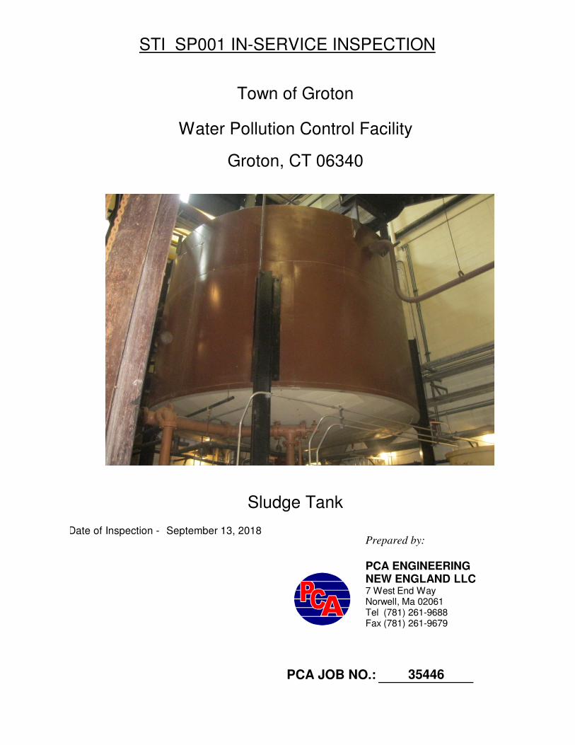
Sludge Tank
Groton, CT 06340
Prepared by:
PCA ENGINEERINGNEW ENGLAND LLC7 West End WayNorwell, Ma 02061Tel (781) 261-9688 Fax (781) 261-9679

Section I: Summary of Findings & Suitability for Service
Section II: Inspection Information & Tank Overview
Section III: Checklist
Section IV: Shell Drawing & Ultrasonic Thickness Data
Section V: Photographs
TABLE OF CONTENTS
PCA ENGINEERING NE LLC

SUMMARY OF FINDINGS
SECTION I:

SUMMARY OF RESULTS
Tank Description: The sludge tank is a 16, 000 gallon vertically oriented storage tank reported to be installed in 1972. It was originally designed as a Decant tank but was converted. It is constructed of welded carbon steel and is currently storing Sludge. The tank is installed within a building using steel legs on a concrete floor.
Containment:
There is no immediate containment for this tank. The contents would be directed to a tunnel system with drains and sumps that would return the product to the Raw Influent Well.
Shell & Roof & Bottom Plates:
There are several pinholes in the shell plates as a result of internal corrosion. There are two horizontal brackets installed on the shell interior that have trapped product creating a condition for corrosion.
With exception to the isolated areas of corrosion, the ultrasonic thickness
measurements were within 5% of the original nominal thickness of the plates. The shell original thickness is 0.281” and the minimum thickness obtained
measured 0.148” at the area of corrosion. The original thickness for the roof plates is 0.187” and the minimum reading obtained measured 0.200”. The original thickness for the bottom plates is 0.250” and the minimum reading obtained measured 0.237”. Original thicknesses are assumed.
The tank steel supports and concrete footings are in good condition.
Accessories: Inspection of the appurtenances found no unusual conditions. General Findings: An isolated band of corrosion was located on the shell approximately 15” to 21” from the top of the tank corresponding to internal brackets attached to the shell. Recommendations: Repair areas of corrosion on the shell using the following three (3) lap weld patch plates: .
1. 12” x 18” x ¼” 2. 12” x 12” x ¼” 3. 12” x 48” x ¼”
Remove the brackets attached to the shell interior.
PCA ENGINEERING NE LLC

&
INSPECTION INFORMATION
SECTION II
TANK OVERVIEW

Inspection Company:
Address :
Date of Inspection: 9/13/2018 Tank No.:
Previous Inspection: 35446
Inspector:
API-653 Certification No. 24662
INSPECTIONS PERFORMED:
X General Inspection of Tank using STI SP001 Annual Inspection Checklist
X Ultrasonic Thickness Measurements of Shell Plates
Other:
Comments:
Bert PhillipsDrew Lawrence
PCA Job No.:
Reviewed By:
INSPECTION INFORMATION
7 West End Way
PCA Engineering NE LLC
Norwell, MA 02061
Sludge
PCA ENGINEERING NE LLC

TEST PROCEDURES Ultrasonic Thickness and Pit Depth Measurements: An Olympus model 45M ultrasonic thickness gauge with a 0o - 5 MHz dual crystal transducer was used to obtain ultrasonic thickness measurements on the plates. The 45M has A-Scan and B-Scan Verification capabilities.
Measurements were obtained in a grid pattern at representative access
locations on the shell & end plates. Multi-Echo modes were utilized to minimize the effects of coated surfaces.
Areas to be measured were cleaned using a wire brush and then an UltraGel couplant applied to afford an acoustical connection between the probe and steel.
Pit depths were measured using a Thorpe Pit Gauge.
The results of the above tests are listed in Thickness Data Tables and the enclosed PCA Drawings.
PCA ENGINEERING NE LLC

Name Name Name
Number and Street Number and Street Number and Street
00000
City, State, Zip Code City, State, Zip Code City, State, Zip Code
TANK ID
SPECIFICATION:
DESIGN: UL SWRI Horizontal Rectangular
API Other
Manufacturer: Last Repair/Reconstruction Date:
Dimensions (ft): Diameter 16.00 Height 10.00 Width Length Cone 1.00 Capacity: 15541
Construction: Bare Steel Cathodically Protected (Check one A. Galvanic or B. Impressed Current) Date Installed:
Coated Steel Concrete Plastic/Fiberglass 16,000
Double Bottom Double Wall Lined Date Installed:
Containment: Earthen Dike Steel Dike Concrete Synthetic Liner Other Common Holding Area
Manifolded to another containment? Yes No
Dimensions (ft): Diameter Height Width Length Capacity: gallons
CDRM: Type:
Release Prevention Barrier Type:
gallons Last Change of Service Date:
Groton, CT 06340 170 Gary Court
Sludge
Unknown
Vertical
Date Installed:
1/1/1972
Date Installed:
Contents: Sludge Construction Date:Unknown
0
Rated capacity is gallons
STI SP001 AST RECORD
Town of Groton Town of Groton
INSTALLER INFORMATIONOWNER INFORMATION FACILITY INFORMATION
Water Pollution Control Facility45 Fort Hill Road
PCA ENGINEERING NE LLC

CHECKLIST
SECTION III

General Inspection Information:
Retain Until Date: (36 months from inspection date)
Inspector Name:
Tank Inspected (ID #):
For equipment not included in this standard, follow the manufacturer recommended inspection/testing schedules and procedures.
The periodic AST Inspection is intended for monitoring the external AST condition and its containment structure. This visual inspection does not require
a certified inspector. It shall be performed by an owner's inspector who is familiar with the site and can identify changes and developing problems.
Remove promptly upon discovery standing water or liquid in the primary tank, secondary containment area, interstice or spill container. Before discharge to the
environment, inspect the liquids for regulated products or other contaminants and dispose of it properly.
In order to comply with EPA SPCC (Spill Prevention, Control and Countermeasure) rules, a facility must regularly test liquid level sensing devices to ensure proper
operation (40 CFR 112.8(8)(v)).
(*) designates an item in a non-conformance status. This indicates that action is required to address a problem.
Non-conforming items important to tank or containment integrity require evaluation by an engineer experienced in AST design, a certified inspector, or a tank
manufacturer who will determine the corrective action. Note the non-conformance and corresponding corrective action in the comment section.
Retain the completed checklists for 36 months.
Complete this checklist on an annual basis supplemental to the owner monthly-performed inspection lists.
Note: If a change has occurred to the tank system or containment that may effect the SPCC plan, the condition should be evaluated against
then current plan requirement by a Professional Engineer knowledgeable in SPCC development and implementation.
Task
1.1 Containment Check for: Yes No* N/A
structure • Holes or cracks in
containment wall or
floor
• Washout
• Liner Degradation
• Corrosion
• Leakage
• Paint Failure
• Tank Settling
2.1 Foundation Settlement or
foundation washout?
Yes* No
2.2 Concrete pad Cracking or spalling? Yes* No N/A
or ring wall?
Not Applicable
Drew Lawrence
Inspection Guidance:
Item
Inspection Date:
No containment area
STI SP001 ANNUAL INSPECTION CHECKLIST
2.0 Tank Foundation and Supports
1.0 Tank Containment
Prior Inspection Date:
9/13/2021
Sludge
Comments
9/13/2018
Status
AST Inspection Standard September 2011

TaskItem CommentsStatus2.3 Supports Check for corrosion Yes No* N/A
paint failure, etc.
2.4 Water drainage Water drains away
from tank?
Yes No* N/A
2.5 Tank grounding Strap secured and in
good condition?
Yes No* N/A
3.1 Confirm the system is
functional, includes the
wire connections for
galvanic systems
Yes No* N/A
3.2 a. inspect the
operational
components (power
switch, meters, and
alarms).
Yes No* N/A
b. Record hour meter,
ammeter and
voltmeter readings
Yes No* N/A
4.1 Coating Check for coating
failure
Yes* No
4.2 Check for:
• Dents
• Buckling
• Bulging
• Corrosion
• Cracking
Yes* No
4.3 Roof slope Check for low points
and standing water
Yes* No N/A
5.1 Vents Verify that
components are
moving freely and vent
passages are not
obstructed for:
• Emergency vent
covers
• Pressure/vacuum
vent poppets
• Other moving vent
components
Yes* No
Steel
condition
Galvanic
cathodic
protection
system
4.0 Tank Shell, Heads, Roof
Coating system is in god condition
5.0 Tank Equipment
Vent is in good condition, penetrates roof
No dents located
Tank is inside a building
Impressed
current
system
3.0 Cathodic Protection
Tank supports are in good condition
Tank is inside a building
AST Inspection Standard September 2011

TaskItem CommentsStatus5.2 Valves Check the condition of
all valves for leaks,
corrosion and
damage.
Yes* No
5.2.1 Cycle the valve open
and closed and check
for proper operation
Yes No* N/A
5.5.2 Check for proper
operation. (Note that
there may be small , 1/4
inch drain plugs in the
bottom of the valve that
are not visible by
looking from above
only)
Yes No* N/A
5.2.3 Check that the valve is
in proper orientation.
(Note that fuel must be
discharged back to the
tank via a separate pipe
or tubing.)
Yes No* N/A
5.2.4 Check that the valve to
check operation.
(Electric solenoids
can be verified by
listening to the plunger
opening and closing. If
no audible confirmation,
the valve should be
inspected for the
presence and operation
of the
plunger.)
Yes No* N/A
5.2.5 a. Manually cycle the
valve to ensure
components are moving
freely and that the valve
handle or lever has
clearance to allow valve
to close
completely.
Yes No* N/A
b. Valves must not be
wired in open position.
Yes No* N/A
Anti-siphon,
check and
gate valves
Pressure
regulator
valve
No leaks or corrosion around tank valves
Expansion
relief valve
Solenoid
valves
Fire and
shear valves
AST Inspection Standard September 2011

TaskItem CommentsStatusc. Make sure fusible
element is in place and
correctly
positioned.
Yes No* N/A
d. Be sure test ports
are sealed with plug
after testing
is complete and no
temporary test fixture
or component remains
connected to valve.
Yes No* N/A
5.3 Check condition of
equipment, including:
• The window is
clean and clear in
sight leak gauges.
• The wire
connections of
electronic gauges
for tightness and
corrosion
• Activate the test
button, if
applicable.
Yes No* N/A
5.4 a. If corrosion damage,
or water has
compromised the ability
of the unit to perform
spill
containment functions,
replace the unit.
Yes* No N/A
b. Inspect the
connections to the AST
for tightness, as well as
the bolts,
nuts, washers for
condition and replace
if necessary.
Yes* No N/A
c. Drain valves must
be operable and
closed
Yes* No N/A
5.5 a. Check that the
strainer is clean and in
good condition.
Yes No* N/A
Spill
containment
boxes on fill
pipe
Interstitial
leak detection
equipment
Strainer
AST Inspection Standard September 2011

TaskItem CommentsStatusb. Access strainer
basket and check cap
and gasket seal as well
as bolts.
Yes No* N/A
5.6 a. Check that the filter is
in good condition and is
within the
manufacturer's expected
service life. Replace if
necessary.
Yes No* N/A
b. Check for leaks and
decreased fuel flow
Yes No* N/A
5.7 Follow manufacturer's
instructions. Check for
corrosion and
blockage of air
passages.
Yes* No N/A
5.8 Test according to
manufacturer's
instructions and
authority having
jurisdiction (AHJ). Verify
leak detectors are suited
and properly installed
for aboveground use.
Yes No* N/A
5.9 a. Has the equipment
been tested to ensure
proper operation?
Yes No* N/A
b. Does equipment
operate as required?
Yes No* N/A
c. Follow
manufacturer's
instructions.
Yes No* N/A
5.10 a. Follow
manufacturer's
instructions and
regulatory
requirements for
inspection and
functionality
verification.
Yes No* N/AOverfill
equipment
Leak detector
for
submersible
pump
systems
Liquid level
equipment
Filter
Flame
arrestors
AST Inspection Standard September 2011

TaskItem CommentsStatusb. Confirm device is
suited for above
ground use by the
manufacture
Yes No* N/A
6.0 Insulated Tanks
6.1 Check condition of
insulation for:
•Missing sections
•Areas of moisture
•Mold
•Damage
Yes* No N/A
6.2 Check for damage that
will allow water intrusion
Yes* No N/A
7.0 Miscellaneous
7.1 Are they in good
condition?
Yes No* N/A
7.2 Ensure that all labels
and tags are intact and
readable.
Yes No* N/A
Additional Comments:
Insulation
cover or
jacket
Labels and
tags
Electrical
wiring and boxes
Insulation
AST Inspection Standard September 2011

&
DRAWINGS
ULTRASONIC THICKNESS DATA
SECTION IV:

16.00
Tank Dimensions in (ft)
-01
NTS
1.00
10.00
Groton, CT 06340
NORWELL, MA 02061 Tel (781) 261-9688 SludgeTank No.
PCA ENGINEERING NE LLC OVERVIEW
9/13/18
35446
7 WEST END WAY Town of Groton
6" Nozzle
DRAWN BY:
BPDESIGN BY: APPROVED BY:
DATE: SCALE: DATE:
DRAWING NUMBER:
DRAWING TITLE:
Roof Plates
Access Hatch
Manway
3" PLG
4" Vent
6" Fill
8" Nozzle
6" Nozzle
12" X 18" Patch Plate
(recommended)
12" X 12" Patch Plate (recommended)
12" X 48" Patch Plate
(recommended)

Bottom Plates
Average
Maximum Repairs Are Required
Minimum
Original Tank Dimensions in (ft)
ULTRASONIC THICKNESS MEASUREMENTS
-01
1 '
Town of Groton Groton, CT 06340
SludgeTank No.
9/13/18 35446
PCA ENGINEERING NE LLC
NORWELL, MA 02061 Tel (781) 261-9688
7 WEST END WAY
0.148
0.281 0.187 0.250
0.247
0.258
0.2370.200
Shell Plates Roof Plates
0.218
0.2470.279
0.279
10 '
1 2 3 4 56 7 8
Roof Plates
Bottom Plates
DRAWN BY:
BPDESIGN BY: APPROVED BY:
DATE: SCALE:
N.T.S.DATE:
DRAWING NUMBER:
DRAWING TITLE:
9
10
11
Pinholes

1. 3. 5. 7. 9.
2. 4. 6. 8. 10.
11.
0.261 0.258
ULTRASONINC THICKNESS MEASUREMENTS (in)
0.221
AREA No. AREA No. AREA No. AREA No.
0.260
0.201 0.198 0.242 0.244
AREA No.
0.210 0.249
0.256
0.174 0.148 0.259 0.261
0.260 0.261
0.260 0.261 0.259 0.258
0.241 0.259
0.248
0.261
0.235
0.260
0.260 0.260 0.278 0.247
0.276
0.246 0.247 0.229 0.235
0.255 0.240
0.261 0.259 0.260 0.247
0.240 0.247
0.240
0.237
0.243 0.244 0.260 0.261
0.2450.219 0.261
0.200 0.246 0.244 0.275
0.249 0.259
0.261
0.243
0.209
0.151 0.251 0.258 0.259
0.208
0.261 0.247 0.250 0.247
0.259 0.248
0.261 0.279 0.247 0.259
0.259 0.247
0.247
0.213
0.235
0.261 0.259 0.234 0.247
0.216
0.255 0.240 0.255 0.276
0.275 0.260
0.243 0.256 0.261 0.261
0.251 0.260
0.213
0.258
0.255
0.258
0.241
0.242
0.242
0.242
0.254
0.242
0.237

270O
0.249
180O
0.249
90O
0.249
0O
0.2648" Suction
0.162
0.250
0.280
0.197
0.162
0.249
0.280
0.197
0.279
0.196
BOTTOM APPURTENANCES
0O
0.182
0.249
0.280
0.195
6" Nozzle
6" Nozzle
Old Decant Nozzle
SHELL APPURTENANCES
8" Nozzle
90O
180O
270O
0.168
0.148
0.126
0.1230.121
0.169
0.127
0.122
0.168
0.126
0.122
20" Manway w/ 6" Nozzle
3" Product Level Gauge
4" Vent
0.249
90O
ROOF APPURTENANCES 0O
180O
270O
0.152
0.124
ULTRASONINC THICKNESS MEASUREMENTS (in)
0o
90o
180o
270o

PHOTOGRAPHS
SECTION V:

Top of tank-appurtenances
PHOTO NO. 1
Sludge Tank
PHOTO NO. 2
PCA ENGINEERING NE LLC

Bottom of tank
PHOTO NO. 4
Shell apputenances
PHOTO NO. 3
PCA ENGINEERING NE LLC

Areas of corrosion and leaking located on shell
PHOTO NO. 6
Interior corrosion area on shell-pinholes
PHOTO NO. 5
PCA ENGINEERING NE LLC

PHOTO NO. 7
Recommended lap patch plate repairs
PCA ENGINEERING NE LLC

Notwithstanding anything contained in this report, nothing herein shall be construed as a representation,
warranty or guarantee, either expressed or implied, regarding the future structural integrity or future life
expectency of any of the items tested. This report and any analysis provided is in all rerspects subject to and
shall be interpreted within the limitations and parameters of the test procedures performed. In the event
testing is performed using a sampling procedure, this report and any analysis shall be limited to those areas
actually tested and the type of tesrt conducted, and the customer is cautioned not to extrapolate the results
of the test samples.