september 2017 doc.: ieee 802.11-17/1321r0 features ... formmwdistribution networkuse case ......
TRANSCRIPT
Submission
doc.: IEEE 802.11-17/1321r0September 2017
Djordje Tujkovic, FacebookSlide 1
Features for mmW Distribution Network Use Case
Date: 2017-10-13
Name Affiliations Address Phone email Djordje Tujkovic Facebook 1 Hacker Way, Menlo Park, CA
94025, USA +1-650-796-9812 [email protected]
Krishna Gomadam Facebook 1 Hacker Way, Menlo Park, CA 94025, USA
+1408-922-1907 [email protected]
Nabeel Ahmed Facebook 1 Hacker Way, Menlo Park, CA 94025, USA
+1-650-739-9764 [email protected]
Michael Grigat
Deutsche Telekom AG Deutsche-Telekom-Allee 7, 64372 Darmstadt, Germany
+49 6151 58 33533
Christoph Lange
Deutsche Telekom AG
Winterfeldtstr. 21, 10781 Berlin, Germany;
+49 30 835358847
Authors:

Submission
doc.: IEEE 802.11-17/1321r0September 2017
Djordje Tujkovic, FacebookSlide 2
Abstract
• Contribution in [1] introduced the initial set of changes to IEEE 802.11ay [2] in support of mmW distribution network use cases [3]
• This presentation introduces additional details to illustrate example L2 features important for [3]• TDD/TDM slot structure and dynamic L2 scheduling support• Beamforming (BF) acquisition for network (NW) initialization• Periodic Beamforming and Interference scan
• We are soliciting feedback to enhance these features and encourage technical contributions to help the standardization of mmW distribution network use case

Submission
doc.: IEEE 802.11-17/1321r0
Djordje Tujkovic, FacebookSlide 3
mmWave Distribution Network Use Cases [3]
September 2017
Small cell
Wi-Fi AP Fiber PoP
(cabinet)
WTTH Small cell
WTTHWi-Fi-
APAlternative:
Wireless inhouse
RGW
mmWave Distribution Network• LOS 60 GHz narrow beam system • Own management and control per
mmWave wireless access area• Route control protocol supports re-
routing over radio links • Auto-alignment installations via
adaptive beamforming• Redundancy of active equipment at
“first” pole next to fiber PoP or via connections to 2 or more fiber PoPs
• Radio link degradation and outage recognition w/ failure localisation
Use case c) WiFi AP / SC
fiber
ProviderNetwork
mmWave APmmWave link
Fiber PoP (to Provider
Network)
Use casea) WTTH
Use caseb) WTTB

Submission
doc.: IEEE 802.11-17/1321r0
Djordje Tujkovic, FacebookSlide 4
High Level NW Architecture
September 2017
Cloud controller
Transport
Internet
Distribution Nodes (DNs)
Client Nodes (CNs)
Datacenter
Small cell WiFi AP Ethernet
POP
• E2E Cloud controller• Self-organizing aspect of NW operation • Improves service quality based on real-
time analytics and anomaly detection• Optimal transport resource utilization to
simplify network planning, deployment and operation
• NW initialization, SW upgrades, interference management, traffic engineering/ SLA, congestion control, security, failure recovery, NMS, VN, etc
• L2 features • Developed on embedded processor based
on PHY/MAC FW/Driver APIs
• NPU user space • E2E client, L3 routing and NMS agents

Submission
doc.: IEEE 802.11-17/1321r0
Djordje Tujkovic, FacebookSlide 5
Main NW States With Impact to L2
September 2017
NW planning
and installation
Add new nodes/ NW extension
NW initialization
Steady state
Catastrophic failure
recovery

Submission
doc.: IEEE 802.11-17/1321r0
Djordje Tujkovic, FacebookSlide 6
Slot Structure in Steady State
September 2017
Time Period Typical Duration DescriptionSlot 66us Unidirectional (Tx or Rx), unequal length in general. Guard periods
(4-8usec) in-between slots to ensure synchronization jitter and propagation delay don’t degrade performance
Frame 400us Consists of one Tx subframe and one Rx subframe. Typical 3 slots per subframe.
Superframe 1.6ms Events across nodes in a network are synchronized to super-frameboundaries and numbers. Typical 4 frames per superframe.
BWGD 25.6ms Bandwidth grant duration. Schedule (slot allocation bitmap)exchanged once every BWGD (retransmission upon failure). Typical 16 superframes per BWGD.
IntelSlide 6
Superframe 0
Frame 0
Slot 0 Slot 1 Slot 2 Slot 3 Slot 4 Slot 5
……
BWGD n+1
Superframe 1 Superframe K-1
Frame 1 Frame L-1 ……
BWGD n

Submission
doc.: IEEE 802.11-17/1321r0
Djordje Tujkovic, FacebookSlide 7
Data and Management plane
September 2017
IntelSlide 7
• DN nodes synchronized via GPS for TDD sub-frame level timing alignment across the network (NW) [1]• CNs track timing from serving DN• 1usec maximum drift any given time (TSF resolution)
• Service Periods (SP) as slots for TDD/TDM access• Data plane
• Standard 802.11ad/ay frames• (B)ACK delayed to next available slot in opposite direction
• Management plane based on new set of IEs exchanged via action or announcement frames• Custom payload to support new L1/L2 procedures

Submission
doc.: IEEE 802.11-17/1321r0
Djordje Tujkovic, FacebookSlide 8
Keep-alive (KA) signaling
• One or more IE’s to provide support for:• Bandwidth (BW) requests from CN to DN and DN to DN• Exchange of slot allocation bitmaps• Link quality measurement feedback (eg, SNR, PER, RSSI, etc) for
MCS selection and Tx power control • Acknowledgement of KA frame reception in opposite direction• Optionally includes 802.11ad/ay time stamps for OTA timing
synchronization of CNs• Typically periodic exchange (e.g., once per BWGD)
September 2017

Submission
doc.: IEEE 802.11-17/1321r0
Djordje Tujkovic, FacebookSlide 9
Odd and Even Node Polarity
September 2017
IntelSlide 9
First TDD sub-frame Second TDD sub-frame
O
O
OO
O
O
OO
E E
E
E
E E
E
E
• Even (E) nodes are transmiting (receiving) only in the first (second) TDD subframe• Odd (O) nodes are receiving (transmitting) only in first (second) TDD subframe
Sim
ulta
neou
s
Submission
doc.: IEEE 802.11-17/1321r0
Djordje Tujkovic, FacebookSlide 10
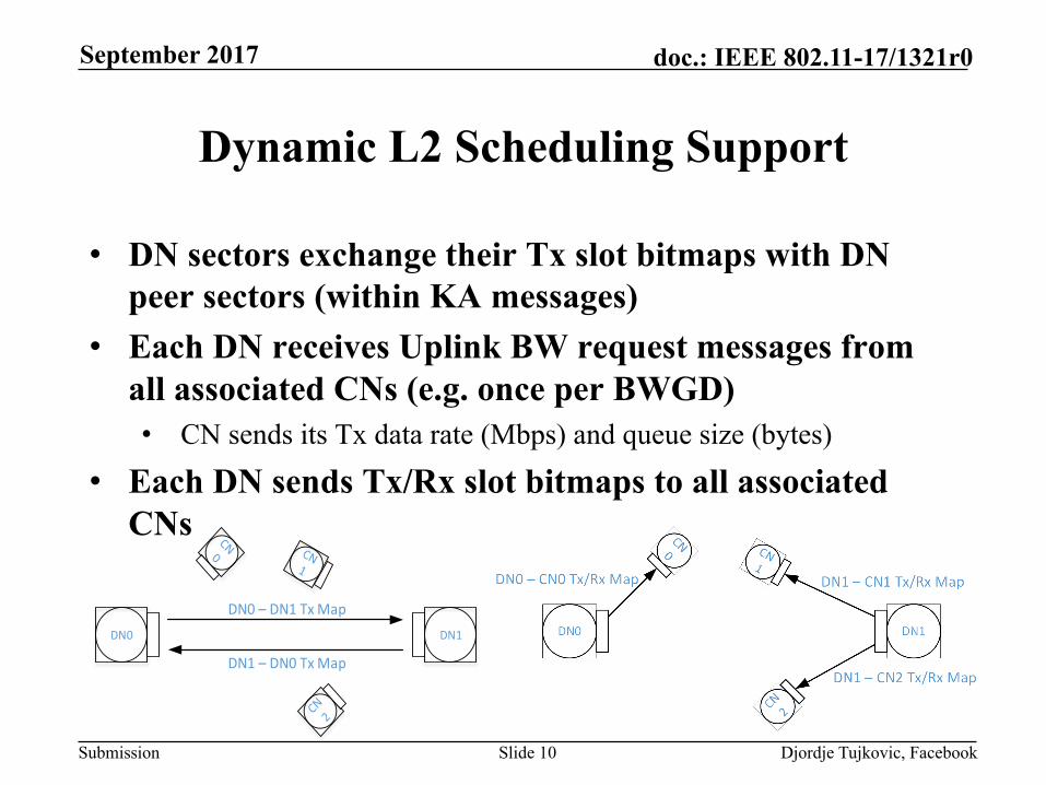
Dynamic L2 Scheduling Support
• DN sectors exchange their Tx slot bitmaps with DN peer sectors (within KA messages)
• Each DN receives Uplink BW request messages from all associated CNs (e.g. once per BWGD)• CN sends its Tx data rate (Mbps) and queue size (bytes)
• Each DN sends Tx/Rx slot bitmaps to all associated CNs
September 2017
DN0 DN1
DN0–DN1TxMap
DN1–DN0TxMap

Submission
doc.: IEEE 802.11-17/1321r0
Djordje Tujkovic, FacebookSlide 11
NW Initialization
• Controller orchestrated multi-cycle process of establishing individual links in the pre-planned mesh topology• Via BF acquisition followed
by OTA node configuration • MAC address of each sector in
mesh topology known to controller prior to initialization• Bar-code on DN/CN sector
box scanned before mounting and sent to controller database via out-of-band (installer app)
September 2017
• Sectors of same DN are wired together and establish IP connection upon boot-up
DN DN DN DN
DNDNPOP
DN DN
CN
DN DN DN
CN
Established link
BF acquisition and OTA configurationNW planned link (to be established)
InitiatorResponder
InitiatorResponder
Init cycle #0
Init cycle #1

Submission
doc.: IEEE 802.11-17/1321r0
Djordje Tujkovic, FacebookSlide 12
Link Establishment
• Newly installed sector boots up in responder mode continuously sweeping beams in Rx mode• Responder does not have information about configuration (e.g., slot
structure, polarity assignment, Golay code assignment or DN/CN role)
• In each initialization cycle, a sector with already established connection to controller is instructed to switch to initiator mode and start BF acquisition with targeted MAC address responder• Initiator starts sweeping of Tx beams with BF training request
(urTrnReq) and using default 802.11ad/ay Golay code• No blind discovery• No broadcast MAC transmission or promiscuous mode reception
September 2017

Submission
doc.: IEEE 802.11-17/1321r0
Djordje Tujkovic, FacebookSlide 13
BF Acquisition Requirements
• Directional beams on both sides of link • Compensate for long distance, i.e., no quasi-omni antennas• Assume reciprocity on reverse link for initiator to receive BF
training response (urTrnRes) from responder
• Initiator could have active traffic with other nodes while instructed to initialize new DN/CN sector• Add new nodes in point-to-multipoint (P2MP) configuration
• CN’s timing unsynchronized with rest of NW• Start with asynchronous scan• Upon the first successful detection of BF training request by
responder, switch to synchronous scan
September 2017
Submission
doc.: IEEE 802.11-17/1321r0
Djordje Tujkovic, FacebookSlide 14
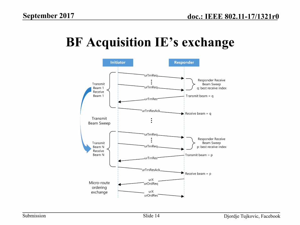
BF Acquisition IE’s exchange
September 2017

Submission
doc.: IEEE 802.11-17/1321r0
Djordje Tujkovic, FacebookSlide 15
Asynchronous Scan Example
September 2017
• Initiator uses only the first slot in each Tx sub-frame per its polarity assignment to transmit urTrnReq
• Allows to maintain traffic on existing links (P2MP) while initializing new ones
~50usec
~20us ~20us~5us

Submission
doc.: IEEE 802.11-17/1321r0
Djordje Tujkovic, FacebookSlide 16
Synchronous Scan Example
September 2017
• Initiator behavior does not change relative to asynchronous scan
• Responder synchronizes its Rx beam switching to overlap with initiator transmission in the first slot of its Rx TDD subframe
• This is not very important for BF acquisition stage (nothing to be saved in Rx slot occupancy) but it is crucial for periodic BF scan in steady state

Submission
doc.: IEEE 802.11-17/1321r0
Djordje Tujkovic, FacebookSlide 17
Over the Air Configuration
• Upon completion of synchronous sweep for all configured transmit beams, initiator sets the flag in urTrnReq to stop further training• Responder and initiator subsequently exchange the best beam indexes
to be used in each direction (urOrdReq and urOrdR exchange)
• Before entering steady state where responder is ready to receive/ transmit user traffic, another 3-way handshake occurs to configure newly ignited sector with:• Slot structure, security keys, polarity assignment, Golay code
assignment and DN/CN role• This can be viewed as light Association/ Authentication• 3-way handshake uses also the first slot only
September 2017

Submission
doc.: IEEE 802.11-17/1321r0
Djordje Tujkovic, FacebookSlide 18
Periodic BF and Interference Scan
• Periodic BF scan is equivalent to Sync BF Acquisition • As a result of BF scan, each side of link can decide to unilaterally
refine its Tx and/or Rx beams in vicinity of operating BF indexes (aka BF refinement)
• Large BF index changes (aka BF switching) are coordinated to occur at the same super-frame boundary on both sides of link
• Interference scan is largely equivalent to Synchronous BF Acquisition with few exceptions• Initiator simultaneously trains multiple responders which are in
steady state but not associated with given initiator • Training involves broadcast-MAC address• Each responder sends measurement results back to controller
September 2017

Submission
doc.: IEEE 802.11-17/1321r0September 2017
Djordje Tujkovic, FacebookSlide 19
Summary
• This presentation introduced additional details to illustrate example L2 features important for mmWdistribution network use cases concept [3]• TDD/TDM slot structure and dynamic L2 scheduling support• Beamforming (BF) acquisition for network (NW) initialization• Periodic Beamforming and Interference scan
• We are soliciting feedback to enhance these features and encourage technical contributions to help the standardization of newly introduced mmW distribution network use cases
Submission
doc.: IEEE 802.11-17/1321r0
Djordje Tujkovic, FacebookSlide 20
References
[1] IEEE 802.11-17/1022r0 “Changes to IEEE 802.11ay in support of mmW Distribution Network Use Cases” , Berlin (Germany), July 2017
[2] IEEE P802.11ayTM/D0.3, March 2017 [3] IEEE 802.11-17/1019r2 “mmWave Mesh Network Usage
Model”, Berlin (Germany), July 2017
September 2017
Submission
doc.: IEEE 802.11-17/1321r0
Djordje Tujkovic, FacebookSlide 21
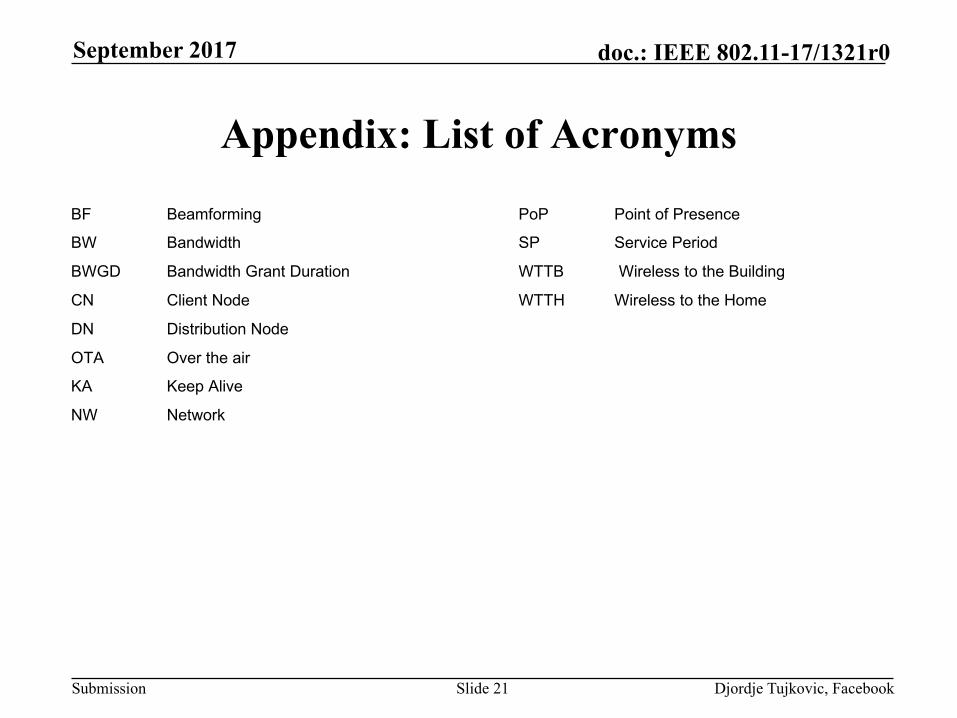
Appendix: List of Acronyms
September 2017
PoP Point of Presence
SP Service Period
WTTB Wireless to the Building
WTTH Wireless to the Home
BF Beamforming
BW Bandwidth
BWGD Bandwidth Grant Duration
CN Client Node
DN Distribution Node
OTA Over the air
KA Keep Alive
NW Network

Submission
doc.: IEEE 802.11-17/1321r0
Djordje Tujkovic, FacebookSlide 22
Appendix: Unequal Slot Length Example
• Separate BA from Data and Management frames via dedicated BA slot• Improves efficiency of slot packing for asymmetric UL/ DL traffic• Prevents stalling of Tx link when no corresponding Rx slot
allocation for sending BACK available • Any received data frames immediately acknowledged in the next
sub-frame• Prioritize Management + ACK over Data frames within slot • For Point-to-Point, combine everything into single slot to
minimize guard period overhead
September 2017
Management, ACK, Data Management, ACK, Data BA
Slot 1 Slot 2 Slot 3