sepia – a new single pixel receiver at the apex telescope · v. belitsky et al.: sepia – a new...
TRANSCRIPT

Astronomy & Astrophysics manuscript no. SEPIA c©ESO 2017December 21, 2017
SEPIA – a New Single Pixel Receiver at the APEX TelescopeV. Belitsky1, 2, I. Lapkin1, 2, M. Fredrixon1, 2, D. Meledin1, 2, E. Sundin1, 2, B. Billade2, S.-E. Ferm1, 2, A. Pavolotsky1, 2,
H. Rashid1, M. Strandberg1, 2, V. Desmaris1, A. Ermakov1, S. Krause1, M. Olberg2, P. Aghdam1, 2, S. Shafiee1, 2, P.Bergman2, E. De Beck2, H. Olofsson2, J. Conway2, C. De Breuck3, K. Immer3, P. Yagoubov3, F.M.
Montenegro-Montes4, K. Torstensson4, J.-P. Pérez-Beaupuits4, T. Klein4, W. Boland5, A. M. Baryshev5, R. Hesper5, J.Barkhof5, J. Adema5, M. E. Bekema5, and A. Koops5
(Affiliations can be found after the references)
Received; accepted
ABSTRACT
Context. We describe the new SEPIA (Swedish-ESO PI Instrument for APEX) receiver, which was designed and built by GARD OSO in collabo-ration with ESO. It was installed and commissioned at the APEX telescope during 2015 with an ALMA Band 5 receiver channel and updated witha new frequency channel (ALMA Band 9) in February 2016.Aims. This manuscript provides a reference for observers who use the SEPIA receiver in terms of the hardware description, optics and performanceas well as the commissioning results.Methods. Out of three available receiver cartridge positions in SEPIA, the two current frequency channels, corresponding to ALMA Band 5,the RF band 158–211 GHz, and Band 9, the RF band 600–722 GHz, provide state-of-the-art dual polarization receivers. The Band 5 frequencychannel uses 2SB SIS mixers with an average SSB noise temperature around 45 K with IF (intermediate frequency) band 4–8 GHz for eachsideband providing total 4 × 4 GHz IF band. The Band 9 frequency channel uses DSB SIS mixers with a noise temperature of 75–125 K with IFband 4–12 GHz for each polarization.Results. Both current SEPIA receiver channels are available to all APEX observers.
Key words. Instrumentation: detectors, Techniques: spectroscopic, Submillimeter: general
1. Introduction
APEX, the Atacama Pathfinder Experiment telescope, is a col-laboration between the Onsala Space Observatory (OSO), theEuropean Southern Observatory (ESO), and the Max-Planck-Institut für Radioastronomie (MPIfR) to construct and oper-ate a modified ALMA prototype antenna as a single dish onthe high altitude site (5105 m) of the Llano Chajnantor, Chile.The telescope was manufactured by VERTEX Antennentechnikin Duisburg, Germany and is a 12 m diameter Cassegrain an-tenna with a surface r.m.s. better than 15 µm, two Nasmyth anda central Cassegrain cabins for instrumentation. Details on thetelescope, site, and instruments can be found at http://www.apex-telescope.org/ and in Güsten et al. (2006). The newSEPIA (Swedish-ESO PI Instrument for the APEX telescope)receiver was brought to APEX in the beginning of 2015 via ajoint effort from GARD OSO and ESO. GARD performed theoptics and cryostat design and construction and the refurbish-ing of the Band 5 pre-production cartridge (owned by ESO, ear-lier built by GARD under European Community FP6 fundedproject) with the full-production LO system and Warm CartridgeAssembly, both provided by NRAO via ESO. GARD has builtthe control system and software, installed the SEPIA receiverin the APEX Cabin A and performed technical commissioning.Initially, the SEPIA receiver contained only an updated ALMABand 5 pre-production receiver cartridge (Billade et al. 2012) toaddress the growing interest in future observations with Band 5at ALMA (first available during cycle 5). The ALMA Band 5center frequency nearly coincides with the 183.3 GHz water ab-sorption line. The key applications of the Band 5 receivers forALMA range from observations of the 313 − 220 H2O line at
183.310 GHz in both Galactic objects and nearby galaxies (e.g.Humphreys et al. 2017) to the 158 µm emission line of C+ fromhigh redshift galaxies (Laing et al. 2010). In the beginning of2016, SEPIA was equipped with an additional ALMA Band 9cartridge (Baryshev et al. 2015), providing observers with twostate-of-the-art, single-pixel, dual polarization receivers deliver-ing each a total 16 GHz IF band. The realization of the SEPIAreceiver project took about one year from the moment the deci-sion was taken, February-March 2014, to the time SEPIA wasinstalled at APEX in February 2015. The success of the SEPIAproject was guaranteed by ESO, providing optical windows andfilters, access to hardware from ALMA, support from NRAOby providing local oscillator (LO), Band 5 warm cartridge as-sembly (WCA) and FE bias electronics – all purchased by ESO.GARD OSO expertise in designing and constructing mm-wavereceivers, in particular the ALMA Band 5 receiver and a longtime heritage of APEX instrumentation, allowed the success-ful completion of the entire project over this short time. In thismanuscript, the SEPIA receiver design, the receiver channel per-formance and the commissioning results are described.
2. SEPIA Receiver design
2.1. Optics
One of the major challenges of bringing the SEPIA receiver withinstalled ALMA cartridges to the APEX telescope is the neces-sity to implement tertiary optics, which should not only providethe required and frequency independent illumination of the sec-ondary but also be compatible with the existing optical layout ofthe APEX Cabin A where all single-pixel heterodyne receivers
Article number, page 1 of 12
arX
iv:1
712.
0739
6v1
[as
tro-
ph.I
M]
20
Dec
201
7
A&A proofs: manuscript no. SEPIA
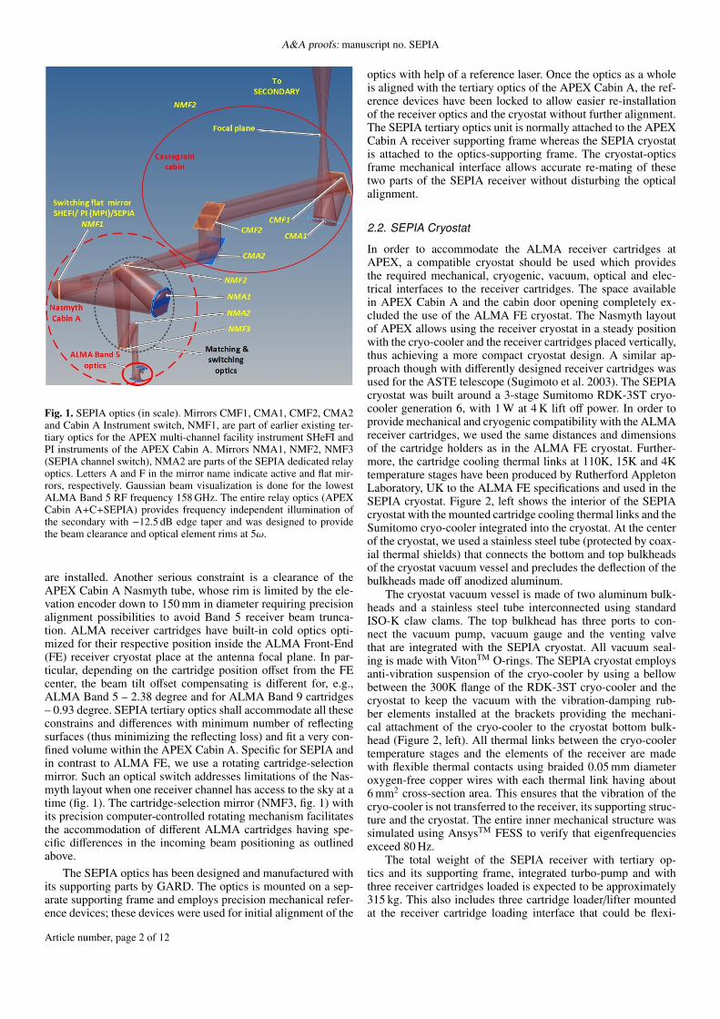
Fig. 1. SEPIA optics (in scale). Mirrors CMF1, CMA1, CMF2, CMA2and Cabin A Instrument switch, NMF1, are part of earlier existing ter-tiary optics for the APEX multi-channel facility instrument SHeFI andPI instruments of the APEX Cabin A. Mirrors NMA1, NMF2, NMF3(SEPIA channel switch), NMA2 are parts of the SEPIA dedicated relayoptics. Letters A and F in the mirror name indicate active and flat mir-rors, respectively. Gaussian beam visualization is done for the lowestALMA Band 5 RF frequency 158 GHz. The entire relay optics (APEXCabin A+C+SEPIA) provides frequency independent illumination ofthe secondary with −12.5 dB edge taper and was designed to providethe beam clearance and optical element rims at 5ω.
are installed. Another serious constraint is a clearance of theAPEX Cabin A Nasmyth tube, whose rim is limited by the ele-vation encoder down to 150 mm in diameter requiring precisionalignment possibilities to avoid Band 5 receiver beam trunca-tion. ALMA receiver cartridges have built-in cold optics opti-mized for their respective position inside the ALMA Front-End(FE) receiver cryostat place at the antenna focal plane. In par-ticular, depending on the cartridge position offset from the FEcenter, the beam tilt offset compensating is different for, e.g.,ALMA Band 5 – 2.38 degree and for ALMA Band 9 cartridges– 0.93 degree. SEPIA tertiary optics shall accommodate all theseconstrains and differences with minimum number of reflectingsurfaces (thus minimizing the reflecting loss) and fit a very con-fined volume within the APEX Cabin A. Specific for SEPIA andin contrast to ALMA FE, we use a rotating cartridge-selectionmirror. Such an optical switch addresses limitations of the Nas-myth layout when one receiver channel has access to the sky at atime (fig. 1). The cartridge-selection mirror (NMF3, fig. 1) withits precision computer-controlled rotating mechanism facilitatesthe accommodation of different ALMA cartridges having spe-cific differences in the incoming beam positioning as outlinedabove.
The SEPIA optics has been designed and manufactured withits supporting parts by GARD. The optics is mounted on a sep-arate supporting frame and employs precision mechanical refer-ence devices; these devices were used for initial alignment of the
optics with help of a reference laser. Once the optics as a wholeis aligned with the tertiary optics of the APEX Cabin A, the ref-erence devices have been locked to allow easier re-installationof the receiver optics and the cryostat without further alignment.The SEPIA tertiary optics unit is normally attached to the APEXCabin A receiver supporting frame whereas the SEPIA cryostatis attached to the optics-supporting frame. The cryostat-opticsframe mechanical interface allows accurate re-mating of thesetwo parts of the SEPIA receiver without disturbing the opticalalignment.
2.2. SEPIA Cryostat
In order to accommodate the ALMA receiver cartridges atAPEX, a compatible cryostat should be used which providesthe required mechanical, cryogenic, vacuum, optical and elec-trical interfaces to the receiver cartridges. The space availablein APEX Cabin A and the cabin door opening completely ex-cluded the use of the ALMA FE cryostat. The Nasmyth layoutof APEX allows using the receiver cryostat in a steady positionwith the cryo-cooler and the receiver cartridges placed vertically,thus achieving a more compact cryostat design. A similar ap-proach though with differently designed receiver cartridges wasused for the ASTE telescope (Sugimoto et al. 2003). The SEPIAcryostat was built around a 3-stage Sumitomo RDK-3ST cryo-cooler generation 6, with 1 W at 4 K lift off power. In order toprovide mechanical and cryogenic compatibility with the ALMAreceiver cartridges, we used the same distances and dimensionsof the cartridge holders as in the ALMA FE cryostat. Further-more, the cartridge cooling thermal links at 110K, 15K and 4Ktemperature stages have been produced by Rutherford AppletonLaboratory, UK to the ALMA FE specifications and used in theSEPIA cryostat. Figure 2, left shows the interior of the SEPIAcryostat with the mounted cartridge cooling thermal links and theSumitomo cryo-cooler integrated into the cryostat. At the centerof the cryostat, we used a stainless steel tube (protected by coax-ial thermal shields) that connects the bottom and top bulkheadsof the cryostat vacuum vessel and precludes the deflection of thebulkheads made off anodized aluminum.
The cryostat vacuum vessel is made of two aluminum bulk-heads and a stainless steel tube interconnected using standardISO-K claw clams. The top bulkhead has three ports to con-nect the vacuum pump, vacuum gauge and the venting valvethat are integrated with the SEPIA cryostat. All vacuum seal-ing is made with VitonTM O-rings. The SEPIA cryostat employsanti-vibration suspension of the cryo-cooler by using a bellowbetween the 300K flange of the RDK-3ST cryo-cooler and thecryostat to keep the vacuum with the vibration-damping rub-ber elements installed at the brackets providing the mechani-cal attachment of the cryo-cooler to the cryostat bottom bulk-head (Figure 2, left). All thermal links between the cryo-coolertemperature stages and the elements of the receiver are madewith flexible thermal contacts using braided 0.05 mm diameteroxygen-free copper wires with each thermal link having about6 mm2 cross-section area. This ensures that the vibration of thecryo-cooler is not transferred to the receiver, its supporting struc-ture and the cryostat. The entire inner mechanical structure wassimulated using AnsysTM FESS to verify that eigenfrequenciesexceed 80 Hz.
The total weight of the SEPIA receiver with tertiary op-tics and its supporting frame, integrated turbo-pump and withthree receiver cartridges loaded is expected to be approximately315 kg. This also includes three cartridge loader/lifter mountedat the receiver cartridge loading interface that could be flexi-
Article number, page 2 of 12
V. Belitsky et al.: SEPIA – a New Single Pixel Receiver at the APEX Telescope
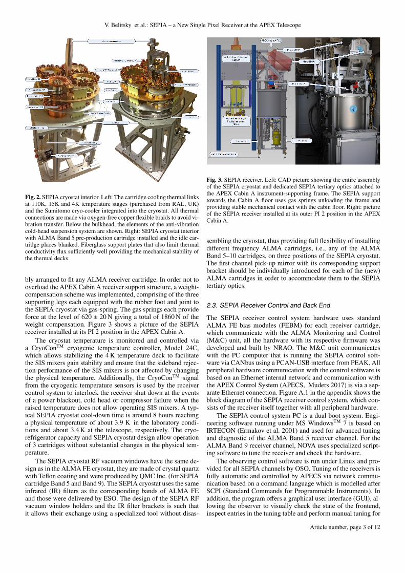
Fig. 2. SEPIA cryostat interior. Left: The cartridge cooling thermal linksat 110K, 15K and 4K temperature stages (purchased from RAL, UK)and the Sumitomo cryo-cooler integrated into the cryostat. All thermalconnections are made via oxygen-free copper flexible braids to avoid vi-bration transfer. Below the bulkhead, the elements of the anti-vibrationcold-head suspension system are shown. Right: SEPIA cryostat interiorwith ALMA Band 5 pre-production cartridge installed and the idle car-tridge places blanked. Fiberglass support plates that also limit thermalconductivity flux sufficiently well providing the mechanical stability ofthe thermal decks.
bly arranged to fit any ALMA receiver cartridge. In order not tooverload the APEX Cabin A receiver support structure, a weight-compensation scheme was implemented, comprising of the threesupporting legs each equipped with the rubber foot and joint tothe SEPIA cryostat via gas-spring. The gas springs each provideforce at the level of 620 ± 20 N giving a total of 1860 N of theweight compensation. Figure 3 shows a picture of the SEPIAreceiver installed at its PI 2 position in the APEX Cabin A.
The cryostat temperature is monitored and controlled viaa CryoConTM cryogenic temperature controller, Model 24C,which allows stabilizing the 4 K temperature deck to facilitatethe SIS mixers gain stability and ensure that the sideband rejec-tion performance of the SIS mixers is not affected by changingthe physical temperature. Additionally, the CryoConTM signalfrom the cryogenic temperature sensors is used by the receivercontrol system to interlock the receiver shut down at the eventsof a power blackout, cold head or compressor failure when theraised temperature does not allow operating SIS mixers. A typ-ical SEPIA cryostat cool-down time is around 8 hours reachinga physical temperature of about 3.9 K in the laboratory condi-tions and about 3.4 K at the telescope, respectively. The cryo-refrigerator capacity and SEPIA cryostat design allow operationof 3 cartridges without substantial changes in the physical tem-perature.
The SEPIA cryostat RF vacuum windows have the same de-sign as in the ALMA FE cryostat, they are made of crystal quartzwith Teflon coating and were produced by QMC Inc. (for SEPIAcartridge Band 5 and Band 9). The SEPIA cryostat uses the sameinfrared (IR) filters as the corresponding bands of ALMA FEand those were delivered by ESO. The design of the SEPIA RFvacuum window holders and the IR filter brackets is such thatit allows their exchange using a specialized tool without disas-
Fig. 3. SEPIA receiver. Left: CAD picture showing the entire assemblyof the SEPIA cryostat and dedicated SEPIA tertiary optics attached tothe APEX Cabin A instrument-supporting frame. The SEPIA supporttowards the Cabin A floor uses gas springs unloading the frame andproviding stable mechanical contact with the cabin floor. Right: pictureof the SEPIA receiver installed at its outer PI 2 position in the APEXCabin A.
sembling the cryostat, thus providing full flexibility of installingdifferent frequency ALMA cartridges, i.e., any of the ALMABand 5–10 cartridges, on three positions of the SEPIA cryostat.The first channel pick-up mirror with its corresponding supportbracket should be individually introduced for each of the (new)ALMA cartridges in order to accommodate them to the SEPIAtertiary optics.
2.3. SEPIA Receiver Control and Back End
The SEPIA receiver control system hardware uses standardALMA FE bias modules (FEBM) for each receiver cartridge,which communicate with the ALMA Monitoring and Control(M&C) unit, all the hardware with its respective firmware wasdeveloped and built by NRAO. The M&C unit communicateswith the PC computer that is running the SEPIA control soft-ware via CANbus using a PCAN-USB interface from PEAK. Allperipheral hardware communication with the control software isbased on an Ethernet internal network and communication withthe APEX Control System (APECS, Muders 2017) is via a sep-arate Ethernet connection. Figure A.1 in the appendix shows theblock diagram of the SEPIA receiver control system, which con-sists of the receiver itself together with all peripheral hardware.
The SEPIA control system PC is a dual boot system. Engi-neering software running under MS WindowsTM 7 is based onIRTECON (Ermakov et al. 2001) and used for advanced tuningand diagnostic of the ALMA Band 5 receiver channel. For theALMA Band 9 receiver channel, NOVA uses specialized script-ing software to tune the receiver and check the hardware.
The observing control software is run under Linux and pro-vided for all SEPIA channels by OSO. Tuning of the receivers isfully automatic and controlled by APECS via network commu-nication based on a command language which is modelled afterSCPI (Standard Commands for Programmable Instruments). Inaddition, the program offers a graphical user interface (GUI), al-lowing the observer to visually check the state of the frontend,inspect entries in the tuning table and perform manual tuning for
Article number, page 3 of 12
A&A proofs: manuscript no. SEPIA
testing purposes. The GUI also provides a plot of the typical at-mospheric transmission at Chajnantor over the frequency bandof the receiver, and marks current LO tuning and sideband lo-cations. Furthermore, a log of all SCPI commands as well as atabular view of raw CANbus readings are provided for debug-ging purposes.
At present, the band 5 and band 9 receivers are controlled viatwo independent programs, which share most of their code base,but differ in parameters and hardware addressing.
The SEPIA receiver uses the XFFTS spectrometer (Kleinet al. 2012) provided as part of the APEX collaboration byMPIfR. The spectrometer has 4–8 GHz × 4 bandwidth, whichcovers 100% of the SEPIA ALMA Band 5 receiver channel IFband and only 4–8 GHz × 2 of the IF band of the SEPIA ALMABand 9 receiver channel whereas the IF band 8–12 GHz is notavailable in the current configuration. An upgrade of the IF sys-tem is planned for late 2018, which will cover 4–12 GHz IFbandwidth.
2.4. SEPIA ALMA Band 5 Receiver Channel
ALMA Band 5 receivers have been developed, designed andsix pre-production cartridges have been built under EC FP 6“Infrastructure Enhancement Program”1. The details of the re-ceiver cartridge design and performance can be found in Billadeet al. (2012). The produced pre-production ALMA Band 5 car-tridges have been delivered to ALMA via ESO. When ALMABand 5 full production started, it was decided to spare the pre-production cartridges and one of those was made available byESO for the APEX SEPIA receiver. Several important modifica-tions have been made by GARD to the pre-production ALMABand 5 cartridge to bring it up-to-date. The most serious up-grade was done to the LO and WCA (Bryerton et al. 2013), thehardware version produced by NRAO for full ALMA Band 5production was used with appropriate changes in the cartridgedesign.
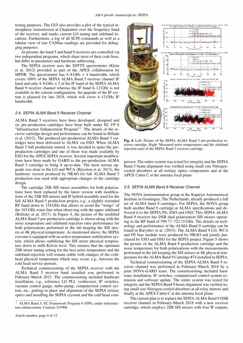
The cartridge 2SB SIS mixer assemblies for both polariza-tions have been replaced by the latest version with modifica-tions of the 2SB SIS mixers and IF hybrid assembly used for thefull ALMA Band 5 production project, e.g., a slightly extendedRF band down to 158 GHz that allows to avoid the “wings” ofthe 183 GHz water line when observing with the upper sideband(Belitsky et al. 2017). In Figure 4, the picture of the modifiedALMA Band 5 pre-production cartridge is shown along with thenoise temperature and sideband rejection ratio performance forboth polarizations performed in the lab keeping the SIS mix-ers at 4K physical temperature. As mentioned above, the SEPIAcryostat is equipped with an active temperature stabilization sys-tem, which allows stabilizing the SIS mixer physical tempera-ture down to milli-Kelvin level. This ensures that the optimum2SB mixer tuning setting for the best noise temperature and thesideband-rejection will remain stable with changes of the cold-head physical temperature which may occur, e.g., between thecold head service periods.
Technical commissioning of the SEPIA receiver with theALMA Band 5 receiver band installed was performed inFebruary-March 2015. The commissioning included hardwareinstallation, e.g., reference LO PLL synthesizer, IF switches,vacuum control gauge, turbo-pump, computerized control sys-tem, etc., putting in place and alignment of the SEPIA tertiaryoptics and installing the SEPIA cryostat and the cold head com-
1 ALMA Band 5, EC Framework Program 6 (FP6), under infrastruc-ture enhancement, Contract 515906
Fig. 4. Left: Picture of the SEPIA ALMA Band 5 pre-production re-ceiver cartridge. Right: Measured noise temperatures and the sidebandrejection ratio of the SEPIA Band 5 receiver cartridge.
pressor. The entire system was tested for integrity and the SEPIABand 5 beam alignment was verified using small size Nitrogen-cooled absorbers at all tertiary optics components and at theAPEX Cabin C at the antenna focal plane.
2.5. SEPIA ALMA Band 9 Receiver Channel
The NOVA instrumentation group at the Kapteyn AstronomicalInstitute in Groningen, The Netherlands, already produced a fullset of ALMA band 9 cartridges. For SEPIA, the NOVA groupbuilt another Band 9 cartridge at ALMA specifications and de-livered it to the SEPIA PIs, ESO and OSO. This SEPIA ALMABand 9 receiver has DSB dual polarization SIS mixers operat-ing in the RF band of 599.77–722.15 GHz. The details on tech-nology and performance of the ALMA Band 9 cartridge can befound in Baryshev et al. (2015). The ALMA Band 9 LO, WCAand FE bias module were produced by NRAO and jointly pur-chased by ESO and OSO for the SEPIA project. Figure 5 showsthe picture of the ALMA Band 9 production cartridge and thenoise temperature for both polarizations with the measurementsperformed in the lab keeping the SIS mixers at 4K physical tem-perature for the ALMA Band 9 Cartridge #74 installed in SEPIA.
Technical commissioning of the SEPIA ALMA Band 9 re-ceiver channel was performed in February–March 2016 by ajoint NOVA-GARD team. The commissioning included hard-ware installation, IF switches, computerized control system ex-tension and software update. The entire system was tested forintegrity and the SEPIA Band 9 beam alignment was verified us-ing small size Nitrogen-cooled absorbers at all relay mirrors andfinally at the APEX Cabin C at the antenna focal plane.
The current plan is to replace the SEPIA ALMA Band 9 DSBreceiver channel in February-March 2018 with a new receivercartridge, which employs 2SB SIS mixers with four IF outputs,
Article number, page 4 of 12
V. Belitsky et al.: SEPIA – a New Single Pixel Receiver at the APEX Telescope
Table 1. Summary of the SEPIA ALMA Band 5 specifications and performance.
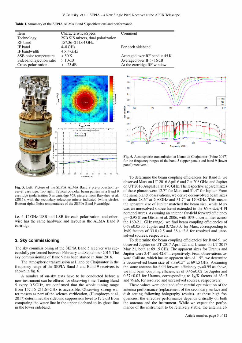
Item Characteristics/Specs CommentTechnology 2SB SIS mixers, dual polarizationRF band 157.36–211.64 GHzIF band 4–8 GHz For each sidebandIF bandwidth 4 × 4 GHzSSB noise temperature < 50 K Averaged over RF band < 45 KSideband rejection ratio > 10 dB Averaged over IF > 16 dBCross-polarization < −23 dB At the cartridge RF window
Fig. 5. Left: Picture of the SEPIA ALMA Band 9 pre-production re-ceiver cartridge. Top right: Typical co-polar beam pattern in a Band 9cartridge (polarization 0 in cartridge #63, picture from Baryshev et al.(2015), with the secondary telescope mirror indicated (white circle).Bottom right: Noise temperatures of the SEPIA Band 9 cartridge.
i.e. 4–12 GHz USB and LSB for each polarization, and other-wise has the same hardware and layout as the ALMA Band 9cartridge.
3. Sky commissioning
The sky commissioning of the SEPIA Band 5 receiver was suc-cessfully performed between February and September 2015. Thesky commissioning of Band 9 has been started in June 2016.
The atmospheric transmission at Llano de Chajnantor in thefrequency range of the SEPIA Band 5 and Band 9 receivers isshown in fig. 6.
A number of on-sky tests have to be conducted before anew instrument can be offered for observing time. Tuning Band5 every 0.5 GHz, we confirmed that the whole tuning rangefrom 157.36–211.64 GHz is accessible. Observing strong wa-ter masers as part of the science verification, (Humphreys et al.2017) determined the sideband suppression level to 17.7 dB fromcomparing the water line in the upper sideband to its ghost linein the lower sideband.
Fig. 6. Atmospheric transmission at Llano de Chajnantor (Paine 2017)for the frequency ranges of the band 5 (upper panel) and band 9 (lowerpanel) receivers.
To determine the beam coupling efficiencies for Band 5, weobserved Mars on UT 2016 April 6 and 7 at 208 GHz, and Jupiteron UT 2016 August 11 at 170 GHz. The respective apparent sizesof these planets were 12.7′′ for Mars and 31.4′′ for Jupiter. Fromthe same planet observations, we derive deconvolved beam sizesof about 28.6′′ at 208 GHz and 31.7′′ at 170 GHz. This meansthe apparent size of Jupiter matched the beam size, while Marswas an unresolved source (semi-extended in the Herschel/HIFInomenclature). Assuming an antenna far-field forward efficiencyη f =0.95 (from Güsten et al. 2006, with 10% uncertainties acrossthe 160-211 GHz range), we find beam coupling efficiencies of0.67±0.05 for Jupiter and 0.72±0.07 for Mars, corresponding toJy/K factors of 33.8±2.5 and 38.4±2.8 for resolved and unre-solved sources, respectively.
To determine the beam coupling efficiencies for Band 9, weobserved Jupiter on UT 2017 April 22, and Uranus on UT 2017May 21, both at 691.5 GHz. The apparent sizes for Uranus andJupiter were 3.4′′ and 42.6′′, respectively. From observations to-ward Callisto, which has an apparent size of 1.5′′, we determinea deconvolved beam size of 8.8±0.5′′ at 691.5 GHz. Assumingthe same antenna far-field forward efficiency η f =0.95 as above,we find beam coupling efficiencies of 0.46±0.02 for Jupiter and0.37±0.03 for Uranus, corresponding to Jy/K factors of 63±3and 79±6, for resolved and unresolved sources, respectively.
These values were obtained after careful optimization of theantenna performance (replacement of the secondary surface anddish setting following holography results). At these high fre-quencies, the effective performance depends critically on boththe antenna and the instrument. While we expect the perfor-mance of the instrument to be relatively stable, the antenna ef-
Article number, page 5 of 12
A&A proofs: manuscript no. SEPIA
Table 2. Summary of the SEPIA ALMA Band 9 specifications and performance.
Item Characteristics/Specs CommentTechnology DSB SIS mixers, dual polarizationRF band 599.77–722.15 GHzIF band 4–12 GHz DSB operationIF bandwidth 2 × 8 GHz Currently limited by the FFTS to 2 × 4 GHzDSB noise temperature 75–125 K Averaged over RF band ≈100 KCross-polarization −15.5 dB At the cartridge RF window
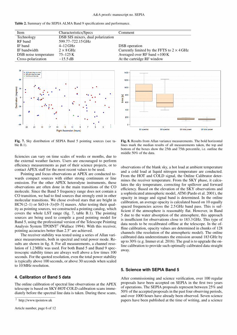
Fig. 7. Sky distribution of SEPIA Band 5 pointing sources (see ta-ble B.1).
ficiencies can vary on time scales of weeks or months, due tothe external weather factors. Users are encouraged to performefficiency measurements as part of their science projects, or tocontact APEX staff for the most recent values to be used.
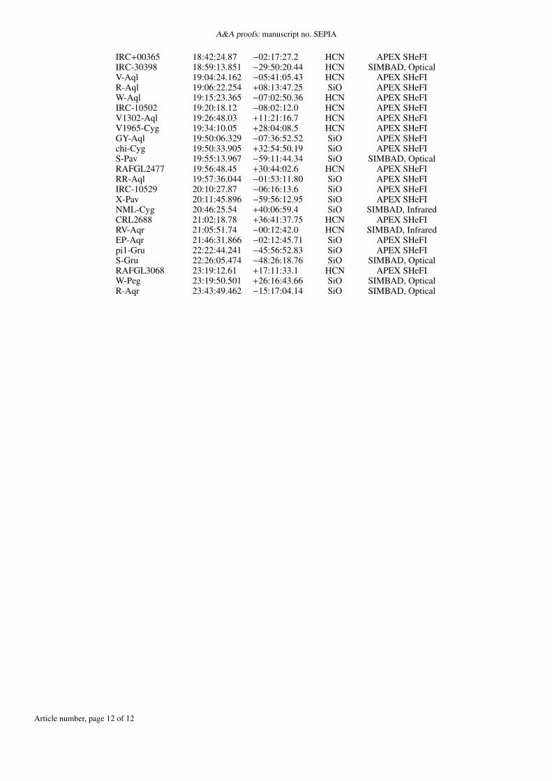
Pointing and focus observations at APEX are conducted to-wards compact sources with either strong continuum or lineemission. For the other APEX heterodyne instruments, theseobservations are often done in the main transitions of the COmolecule. Since the Band 5 frequency range does not contain aCO transition, we had to find sources that strongly emit in othermolecular transitions. We chose evolved stars that are bright inHCN (2–1) or SiO (4–3)v[0–3] masers. After testing their qual-ity as pointing sources, we constructed a pointing catalog, whichcovers the whole LST range (fig. 7, table B.1). The pointingsources are being used to compile a good pointing model forBand 5, using the professional version of the Telescope PointingAnalysis System TPOINT2 (Wallace 1994). With this receiver,pointing accuracies better than 2.5" are achieved.
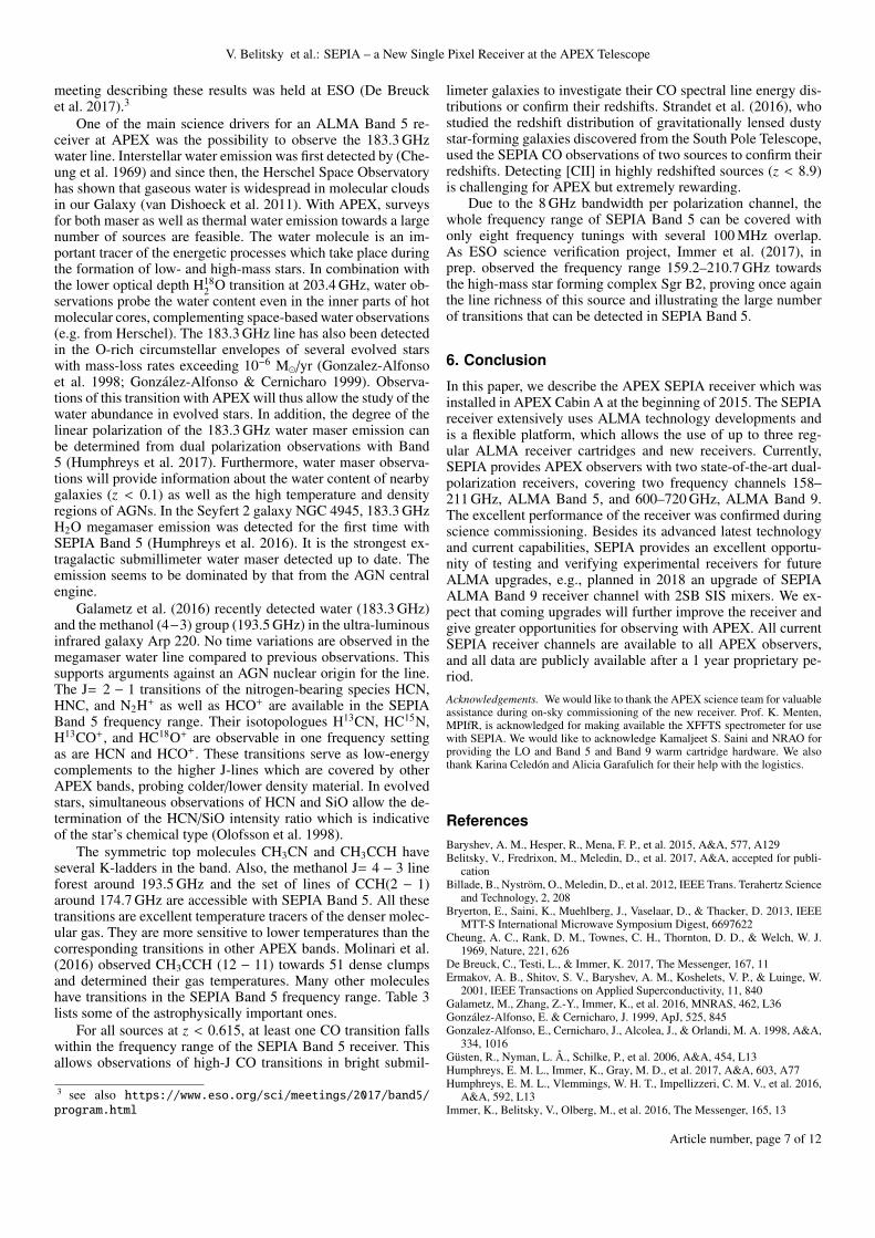
The receiver stability was tested using a series of Allan vari-ance measurements, both in spectral and total power mode. Re-sults are shown in fig. 8. For all measurements, a channel reso-lution of 1.2 MHz was used. For both Band 5 and Band 9 spec-troscopic stability times are always well above a few times 100seconds. For the quoted resolution, even the total power stabilityis typically above 100 seconds, or above 30 seconds when scaledto 10 MHz resolution.
4. Calibration of Band 5 data
The online calibration of spectral line observations at the APEXtelescope is based on SKY-HOT-COLD calibration scans imme-diately before the spectral line data is taken. During these scans,2 http://www.tpointsw.uk
Fig. 8. Results from Allan variance measurements. The bold horizontallines mark the median results of all measurements taken, the top andbottom of the boxes show the 25th and 75th percentile, i.e. outline themiddle 50% of the data.
observations of the blank sky, a hot load at ambient temperatureand a cold load at liquid nitrogen temperature are conducted.From the HOT and COLD signal, the Online Calibrator deter-mines the receiver temperature. From the SKY phase, it calcu-lates the sky temperature, correcting for spillover and forwardefficiency. Based on the elevation of the SKY observations anda sophisticated atmospheric model, ATM (Pardo et al. 2001), theopacity in image and signal band is determined. In the onlinecalibration, an average opacity is calculated based on 10 equallyspaced frequencies across the 2.5 GHz band pass. This is suf-ficient if the atmosphere is reasonably flat. However, in Band5 due to the water absorption of the atmosphere, this approachis insufficient for observations close to 183.3 GHz. This type ofdata needs to be recalibrated offline at the telescope. In the of-fline calibration, opacity values are determined in chunks of 128channels (the resolution of the atmospheric model). The onlinecalibrated data underestimates the emission around 183 GHz byup to 30% (e.g. Immer et al. 2016). The goal is to upgrade the on-line calibration to provide such optimally calibrated data straightaway.
5. Science with SEPIA Band 5
After commissioning and science verification, over 100 regularproposals have been accepted on SEPIA in the first two yearsof operations. The SEPIA proposals represent between 25% and50% of the accepted proposals in the past four observing periods,and over 1000 hours have already been observed. Seven sciencepapers have been published at the time of writing, and a science
Article number, page 6 of 12
V. Belitsky et al.: SEPIA – a New Single Pixel Receiver at the APEX Telescope
meeting describing these results was held at ESO (De Breucket al. 2017).3
One of the main science drivers for an ALMA Band 5 re-ceiver at APEX was the possibility to observe the 183.3 GHzwater line. Interstellar water emission was first detected by (Che-ung et al. 1969) and since then, the Herschel Space Observatoryhas shown that gaseous water is widespread in molecular cloudsin our Galaxy (van Dishoeck et al. 2011). With APEX, surveysfor both maser as well as thermal water emission towards a largenumber of sources are feasible. The water molecule is an im-portant tracer of the energetic processes which take place duringthe formation of low- and high-mass stars. In combination withthe lower optical depth H18
2 O transition at 203.4 GHz, water ob-servations probe the water content even in the inner parts of hotmolecular cores, complementing space-based water observations(e.g. from Herschel). The 183.3 GHz line has also been detectedin the O-rich circumstellar envelopes of several evolved starswith mass-loss rates exceeding 10−6 M�/yr (Gonzalez-Alfonsoet al. 1998; González-Alfonso & Cernicharo 1999). Observa-tions of this transition with APEX will thus allow the study of thewater abundance in evolved stars. In addition, the degree of thelinear polarization of the 183.3 GHz water maser emission canbe determined from dual polarization observations with Band5 (Humphreys et al. 2017). Furthermore, water maser observa-tions will provide information about the water content of nearbygalaxies (z < 0.1) as well as the high temperature and densityregions of AGNs. In the Seyfert 2 galaxy NGC 4945, 183.3 GHzH2O megamaser emission was detected for the first time withSEPIA Band 5 (Humphreys et al. 2016). It is the strongest ex-tragalactic submillimeter water maser detected up to date. Theemission seems to be dominated by that from the AGN centralengine.
Galametz et al. (2016) recently detected water (183.3 GHz)and the methanol (4−3) group (193.5 GHz) in the ultra-luminousinfrared galaxy Arp 220. No time variations are observed in themegamaser water line compared to previous observations. Thissupports arguments against an AGN nuclear origin for the line.The J= 2 − 1 transitions of the nitrogen-bearing species HCN,HNC, and N2H+ as well as HCO+ are available in the SEPIABand 5 frequency range. Their isotopologues H13CN, HC15N,H13CO+, and HC18O+ are observable in one frequency settingas are HCN and HCO+. These transitions serve as low-energycomplements to the higher J-lines which are covered by otherAPEX bands, probing colder/lower density material. In evolvedstars, simultaneous observations of HCN and SiO allow the de-termination of the HCN/SiO intensity ratio which is indicativeof the star’s chemical type (Olofsson et al. 1998).
The symmetric top molecules CH3CN and CH3CCH haveseveral K-ladders in the band. Also, the methanol J= 4 − 3 lineforest around 193.5 GHz and the set of lines of CCH(2 − 1)around 174.7 GHz are accessible with SEPIA Band 5. All thesetransitions are excellent temperature tracers of the denser molec-ular gas. They are more sensitive to lower temperatures than thecorresponding transitions in other APEX bands. Molinari et al.(2016) observed CH3CCH (12 − 11) towards 51 dense clumpsand determined their gas temperatures. Many other moleculeshave transitions in the SEPIA Band 5 frequency range. Table 3lists some of the astrophysically important ones.
For all sources at z < 0.615, at least one CO transition fallswithin the frequency range of the SEPIA Band 5 receiver. Thisallows observations of high-J CO transitions in bright submil-
3 see also https://www.eso.org/sci/meetings/2017/band5/program.html
limeter galaxies to investigate their CO spectral line energy dis-tributions or confirm their redshifts. Strandet et al. (2016), whostudied the redshift distribution of gravitationally lensed dustystar-forming galaxies discovered from the South Pole Telescope,used the SEPIA CO observations of two sources to confirm theirredshifts. Detecting [CII] in highly redshifted sources (z < 8.9)is challenging for APEX but extremely rewarding.
Due to the 8 GHz bandwidth per polarization channel, thewhole frequency range of SEPIA Band 5 can be covered withonly eight frequency tunings with several 100 MHz overlap.As ESO science verification project, Immer et al. (2017), inprep. observed the frequency range 159.2–210.7 GHz towardsthe high-mass star forming complex Sgr B2, proving once againthe line richness of this source and illustrating the large numberof transitions that can be detected in SEPIA Band 5.
6. Conclusion
In this paper, we describe the APEX SEPIA receiver which wasinstalled in APEX Cabin A at the beginning of 2015. The SEPIAreceiver extensively uses ALMA technology developments andis a flexible platform, which allows the use of up to three reg-ular ALMA receiver cartridges and new receivers. Currently,SEPIA provides APEX observers with two state-of-the-art dual-polarization receivers, covering two frequency channels 158–211 GHz, ALMA Band 5, and 600–720 GHz, ALMA Band 9.The excellent performance of the receiver was confirmed duringscience commissioning. Besides its advanced latest technologyand current capabilities, SEPIA provides an excellent opportu-nity of testing and verifying experimental receivers for futureALMA upgrades, e.g., planned in 2018 an upgrade of SEPIAALMA Band 9 receiver channel with 2SB SIS mixers. We ex-pect that coming upgrades will further improve the receiver andgive greater opportunities for observing with APEX. All currentSEPIA receiver channels are available to all APEX observers,and all data are publicly available after a 1 year proprietary pe-riod.Acknowledgements. We would like to thank the APEX science team for valuableassistance during on-sky commissioning of the new receiver. Prof. K. Menten,MPIfR, is acknowledged for making available the XFFTS spectrometer for usewith SEPIA. We would like to acknowledge Kamaljeet S. Saini and NRAO forproviding the LO and Band 5 and Band 9 warm cartridge hardware. We alsothank Karina Celedón and Alicia Garafulich for their help with the logistics.
ReferencesBaryshev, A. M., Hesper, R., Mena, F. P., et al. 2015, A&A, 577, A129Belitsky, V., Fredrixon, M., Meledin, D., et al. 2017, A&A, accepted for publi-
cationBillade, B., Nyström, O., Meledin, D., et al. 2012, IEEE Trans. Terahertz Science
and Technology, 2, 208Bryerton, E., Saini, K., Muehlberg, J., Vaselaar, D., & Thacker, D. 2013, IEEE
MTT-S International Microwave Symposium Digest, 6697622Cheung, A. C., Rank, D. M., Townes, C. H., Thornton, D. D., & Welch, W. J.
1969, Nature, 221, 626De Breuck, C., Testi, L., & Immer, K. 2017, The Messenger, 167, 11Ermakov, A. B., Shitov, S. V., Baryshev, A. M., Koshelets, V. P., & Luinge, W.
2001, IEEE Transactions on Applied Superconductivity, 11, 840Galametz, M., Zhang, Z.-Y., Immer, K., et al. 2016, MNRAS, 462, L36González-Alfonso, E. & Cernicharo, J. 1999, ApJ, 525, 845Gonzalez-Alfonso, E., Cernicharo, J., Alcolea, J., & Orlandi, M. A. 1998, A&A,
334, 1016Güsten, R., Nyman, L. Å., Schilke, P., et al. 2006, A&A, 454, L13Humphreys, E. M. L., Immer, K., Gray, M. D., et al. 2017, A&A, 603, A77Humphreys, E. M. L., Vlemmings, W. H. T., Impellizzeri, C. M. V., et al. 2016,
A&A, 592, L13Immer, K., Belitsky, V., Olberg, M., et al. 2016, The Messenger, 165, 13
Article number, page 7 of 12

A&A proofs: manuscript no. SEPIA
Table 3. Astrophysically important molecular transitions within the frequency coverage of SEPIA Band 5.
Molecule Transition Frequency (GHz) CommentCH3CN J=9−8 165.60 Several K-components
H2S JKa,Kc = 11,1−10,1 168.76HC18O+ J=2−1 170.32CH3CCH J=10−9 170.90 Several K-componentsSiO, v=2 J=4−3 171.28HC15N J=2−1 172.11
SiO, v=1 J=4−3 172.48H13CN J=2−1 172.68H13CO+ J=2−1 173.51SiO, v=0 J=4−3 173.69
CCH N=2−1 174.70 Several linesHCN J=2−1 177.26HCO+ J=2−1 178.38HNC J=2−1 181.32H2O JKa,Kc = 31,3−22,0 183.31
CH3CN J=10−9 183.90 Several K-components13CS J=4−3 184.98N2H+ J=2−1 186.34
CH3CCH J=11−10 187.90 Several K-componentsC34S J=4−3 192.82
CH3OH J=4−3 193.50 Several linesCS J=4−3 195.95
CH3CN J=11−10 202.30 Several K-componentsH18
2 O JKa,Kc = 31,3−22,0 203.41CH3CCH J=12−11 205.00 Several K-components
Klein, B., Hochgürtel, S., Krämer, I., et al. 2012, A&A, 542, L3Laing, R., Maiolino, R., Rykaczewski, H., & Testi, L. 2010, The Messenger, 141Molinari, S., Merello, M., Elia, D., et al. 2016, ApJ, 826, L8Muders, D. 2017, APECS User Manual, Tech. Rep. APEX-MPI-MAN-0011Olofsson, H., Lindqvist, M., Nyman, L.-A., & Winnberg, A. 1998, A&A, 329,
1059Paine, S. 2017, The am atmospheric model (v. 9.2)Pardo, J. R., Cernicharo, J., & Serabyn, E. 2001, IEEE Transactions on Antennas
and Propagation, 49, 1683Strandet, M. L., Weiss, A., Vieira, J. D., et al. 2016, ApJ, 822, 80Sugimoto, M., Sekimoto, Y., Yokogawa, S., et al. 2003, in Fourteenth Interna-
tional Symposium on Space Terahertz Technology, ed. C. Walker & J. Payne,535
van Dishoeck, E. F., Kristensen, L. E., Benz, A. O., et al. 2011, PASP, 123, 138Wallace, P. T. 1994, Starlink User Note, 100
1 Group for Advanced Receiver Development (GARD), Department ofSpace, Earth and Environment, Chalmers University of Technology,41296 Gothenburg, Swedene-mail: [email protected]
2 Department of Space, Earth and Environment, Chalmers Universityof Technology, Onsala Space Observatory (OSO), 43992 Onsala,Sweden
3 European Southern Observatory (ESO), Karl-Schwarzschild-Str. 2,85748 Garching bei München, Germany
4 European Southern Observatory, Alonso de Córdova 3107, Vitacura,Casilla 19001, Santiago de Chile, Chile
5 Netherlands Research School for Astronomy (NOVA), Kapteyn As-tronomical Institute, Landleven 12, 9747 AD Groningen, The Nether-lands
Article number, page 8 of 12
V. Belitsky et al.: SEPIA – a New Single Pixel Receiver at the APEX Telescope
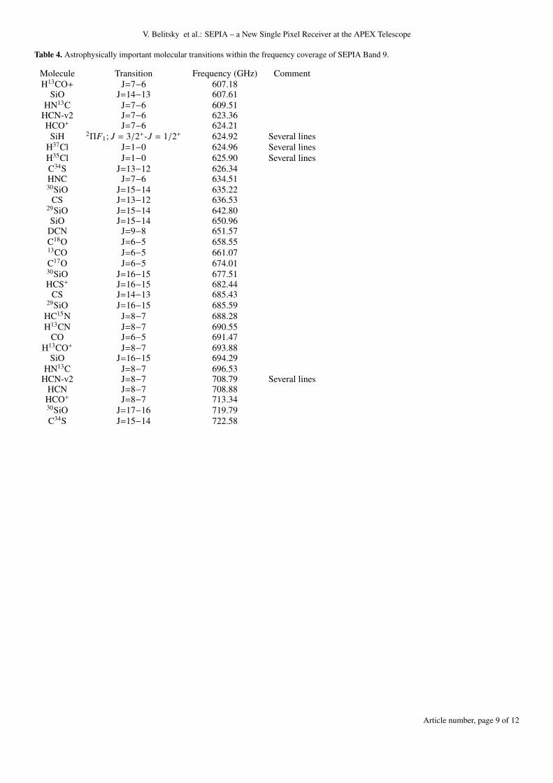
Table 4. Astrophysically important molecular transitions within the frequency coverage of SEPIA Band 9.
Molecule Transition Frequency (GHz) CommentH13CO+ J=7−6 607.18
SiO J=14−13 607.61HN13C J=7−6 609.51
HCN-v2 J=7−6 623.36HCO+ J=7−6 624.21
SiH 2ΠF1; J = 3/2+-J = 1/2+ 624.92 Several linesH37Cl J=1−0 624.96 Several linesH35Cl J=1−0 625.90 Several linesC34S J=13−12 626.34HNC J=7−6 634.5130SiO J=15−14 635.22
CS J=13−12 636.5329SiO J=15−14 642.80SiO J=15−14 650.96
DCN J=9−8 651.57C18O J=6−5 658.5513CO J=6−5 661.07C17O J=6−5 674.0130SiO J=16−15 677.51HCS+ J=16−15 682.44
CS J=14−13 685.4329SiO J=16−15 685.59
HC15N J=8−7 688.28H13CN J=8−7 690.55
CO J=6−5 691.47H13CO+ J=8−7 693.88
SiO J=16−15 694.29HN13C J=8−7 696.53
HCN-v2 J=8−7 708.79 Several linesHCN J=8−7 708.88HCO+ J=8−7 713.3430SiO J=17−16 719.79C34S J=15−14 722.58
Article number, page 9 of 12

A&A proofs: manuscript no. SEPIA
Appendix A: Block diagram
Fig. A.1. Block diagram of the SEPIA receiver control system with allperipheral hardware.
Appendix B: Pointing sources
Article number, page 10 of 12
V. Belitsky et al.: SEPIA – a New Single Pixel Receiver at the APEX Telescope
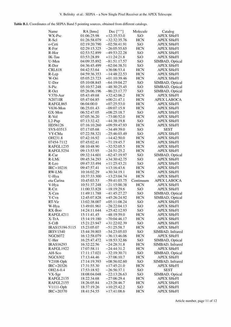
Table B.1. Coordinates of the SEPIA Band 5 pointing sources, obtained from different catalogs.
Name RA [hms] Dec [◦′ ′′] Molecule CatalogWX-Psc 01:06:25.98 +12:35:53.0 SiO APEX SHeFIR-Scl 01:26:58.079 −32:32:35.76 HCN APEX SHeFIo-Ceti 02:19:20.790 −02:58:41.91 SiO APEX SHeFIR-For 02:29:15.325 −26:05:55.65 HCN APEX SHeFIR-Hor 02:53:52.899 −49:53:22.28 SiO APEX SHeFIIK-Tau 03:53:28.89 +11:24:21.8 SiO APEX SHeFIU-Men 04:09:35.892 −81:51:17.57 SiO SIMBAD, OpticalR-Dor 04:36:45.499 −62:04:38.51 SiO APEX SHeFICRL618 04:42:53.64 +36:06:53.4 HCN APEX SHeFIR-Lep 04:59:36.353 −14:48:22.53 HCN APEX SHeFIW-Ori 05:05:23.723 +01:10:39.46 HCN APEX SHeFIU-Dor 05:10:08.845 −64:19:04.27 SiO SIMBAD, OpticalS-Pic 05:10:57.248 −48:30:25.45 SiO SIMBAD, OpticalR-Oct 05:26:06.196 −86:23:17.77 SiO SIMBAD, OpticalV370-Aur 05:43:49.68 +32:42:06.2 HCN APEX SHeFIN2071IR 05:47:04.85 +00:21:47.1 HCN APEX LABOCARAFGL865 06:04:00.0 +07:25:53.0 HCN APEX SHeFIV636-Mon 06:25:01.43 −09:07:15.9 HCN APEX SHeFIGX-Mon 06:52:47.05 +08:25:18.7 SiO APEX SHeFIR-Vol 07:05:36.20 −73:00:52.0 HCN APEX SHeFIL2-Pup 07:13:32.42 −44:38:19.8 SiO APEX SHeFIHD56126 07:16:10.260 +09:59:47.93 HCN APEX SHeFISVS-03513 07:17:05.68 −34:49:39.0 SiO SESTVY-CMa 07:22:58.321 −25:46:03.49 SiO APEX SHeFIOH231.8 07:42:16.92 −14:42:50.0 HCN APEX SHeFI07454-7112 07:45:02.41 −71:19:45.7 HCN APEX SHeFIRAFGL1235 08:10:48.90 −32:52:05.5 HCN APEX SHeFIRAFGL5254 09:13:53.95 −24:51:25.2 HCN APEX SHeFIR-Car 09:32:14.601 −62:47:19.97 SiO SIMBAD, OpticalR-LMi 09:45:34.293 +34:30:42.75 SiO APEX SHeFIR-Leo 09:47:33.494 +11:25:43.21 SiO APEX SHeFIIRC+10216 09:47:57.41 +13:16:43.6 HCN APEX SHeFIRW-LMi 10:16:02.29 +30:34:19.1 HCN APEX SHeFIU-Hya 10:37:33.300 −13:23:04.74 HCN APEX SHeFIeta Carina 10:45:03.53 −59:41:03.75 Continuum APEX LABOCAV-Hya 10:51:37.248 −21:15:00.38 HCN APEX SHeFIR-Crt 11:00:33.828 −18:19:29.6 SiO APEX SHeFIX-Cen 11:49:11.788 −41:45:27.27 SiO SIMBAD, OpticalY-Cvn 12:45:07.828 +45:26:24.92 HCN SIMBAD, OpticalRT-Vir 13:02:38.007 +05:11:08.24 SiO APEX SHeFIW-Hya 13:49:01.961 −28:22:04.13 SiO APEX SHeFIRX-Boo 14:24:11.644 +25:42:12.93 SiO APEX SHeFIRAFGL4211 15:11:41.45 −48:19:59.0 HCN APEX SHeFIX-TrA 15:14:19.180 −70:04:46.17 HCN APEX SHeFIS-CrB 15:21:23.947 +31:22:02.39 SiO APEX SHeFIIRAS15194-5115 15:23:05.07 −51:25:58.7 HCN APEX SHeFIIRSV1540 15:44:39.803 −54:23:05.03 SiO SIMBAD, InfraredNGC6072 16:12:58.079 −36:13:46.06 HCN APEX SHeFIU-Her 16:25:47.472 +18:53:32.86 SiO SIMBAD, OpticalIRAS16293 16:32:22.56 −24:28:31.8 HCN SIMBAD, InfraredRAFGL1922 17:07:58.11 −24:44:31.2 HCN APEX SHeFIAH-Sco 17:11:17.021 −32:19:30.71 SiO SIMBAD, OpticalNGC6302 17:13:44.46 −37:06:10.7 HCN APEX SHeFIV2108-Oph 17:14:19.393 +08:56:02.60 SiO SIMBAD, InfraredIRC+20326 17:31:55.30 +17:45:21.0 HCN APEX SHeFIOH2.6-0.4 17:53:18.92 −26:56:37.1 SiO SESTVX-Sgr 18:08:04.048 −22:13:26.63 SiO SIMBAD, OpticalRAFGL2135 18:22:34.68 −27:06:29.4 HCN APEX SHeFIRAFGL2155 18:26:05.84 +23:28:46.7 HCN APEX SHeFIV1111-Oph 18:37:19.26 +10:25:42.2 SiO APEX SHeFIIRC+20370 18:41:54.55 +17:41:08.6 HCN APEX SHeFI
Article number, page 11 of 12
A&A proofs: manuscript no. SEPIA
IRC+00365 18:42:24.87 −02:17:27.2 HCN APEX SHeFIIRC-30398 18:59:13.851 −29:50:20.44 HCN SIMBAD, OpticalV-Aql 19:04:24.162 −05:41:05.43 HCN APEX SHeFIR-Aql 19:06:22.254 +08:13:47.25 SiO APEX SHeFIW-Aql 19:15:23.365 −07:02:50.36 HCN APEX SHeFIIRC-10502 19:20:18.12 −08:02:12.0 HCN APEX SHeFIV1302-Aql 19:26:48.03 +11:21:16.7 HCN APEX SHeFIV1965-Cyg 19:34:10.05 +28:04:08.5 HCN APEX SHeFIGY-Aql 19:50:06.329 −07:36:52.52 SiO APEX SHeFIchi-Cyg 19:50:33.905 +32:54:50.19 SiO APEX SHeFIS-Pav 19:55:13.967 −59:11:44.34 SiO SIMBAD, OpticalRAFGL2477 19:56:48.45 +30:44:02.6 HCN APEX SHeFIRR-Aql 19:57:36.044 −01:53:11.80 SiO APEX SHeFIIRC-10529 20:10:27.87 −06:16:13.6 SiO APEX SHeFIX-Pav 20:11:45.896 −59:56:12.95 SiO APEX SHeFINML-Cyg 20:46:25.54 +40:06:59.4 SiO SIMBAD, InfraredCRL2688 21:02:18.78 +36:41:37.75 HCN APEX SHeFIRV-Aqr 21:05:51.74 −00:12:42.0 HCN SIMBAD, InfraredEP-Aqr 21:46:31.866 −02:12:45.71 SiO APEX SHeFIpi1-Gru 22:22:44.241 −45:56:52.83 SiO APEX SHeFIS-Gru 22:26:05.474 −48:26:18.76 SiO SIMBAD, OpticalRAFGL3068 23:19:12.61 +17:11:33.1 HCN APEX SHeFIW-Peg 23:19:50.501 +26:16:43.66 SiO SIMBAD, OpticalR-Aqr 23:43:49.462 −15:17:04.14 SiO SIMBAD, Optical
Article number, page 12 of 12