sensor integration module - amazon s3 · the sim2 sensor integration module is designed to provide...
TRANSCRIPT
SIM2SENSOR INTEGRATION MODULE
2428 Palumbo Dr. Lexington, KY USA 40509
Voice 859-269-7760Tech Support 800-622-3526www.elanhomesystems.com

© ELAN Home Systems 2006 • All rights reserved. Page 1
ELAN HOME SYSTEMS SIM2 INSTALLATION MANUAL
Contents
Introduction ....................................................... 2
Connections ...................................................... 4
DIP Switch Settings ......................................... 7
Applications ....................................................... 8
Warranty ............................................. Back Page
Page 2 © ELAN Home Systems 2006 • All rights reserved.
SIM2 INSTALLATION MANUAL ELAN HOME SYSTEMS
IntroductionThe SIM2 Sensor Integration Module is designed to provide dry contact closure or 12 VDC output in response to input status from ELAN®SENSE Automation Sensors in home automation applications. Capable of being used as a stand-alone device, the SIM2 integrates four sensor inputs with two relay outputs and provides simple setup and operation with no programming required. Relays respond to sensor triggers differently based on conditional logic DIP switch settings.
Features
• Stand-Alone Interface for ELANSENSE Automation Sensors
• Any ELANSENSE Sensor Can Trigger Either Of Two On-board Relays
• All Four Sense Inputs Can Be Linked To One Relay
• Conditional Logic AND/OR Settings
• Simple Setup & Operation-No Software Required
Specifi cations
Sense Inputs (x4) .............................................. 3.5mm Stereo Mini Plug
Relay Outputs (x2) ............................................ 8 pin WECO Connection
NO, NC, COM, GND,12VDC
Accepts 24 AWG (Cat-5) Wire
Rated Load ................................................ .5A @ 120VAC or 1A @ 24VDC
Power Output ................................................................. 12VDC @ 650ma
Power Requirements .................................................... 12VDC 2.1 Amps
PWR3 Power Supply Included
Mounting ........................ Adhesive Strip and Mounting Screws Included
© ELAN Home Systems 2006 • All rights reserved. Page 3
ELAN HOME SYSTEMS SIM2 INSTALLATION MANUAL
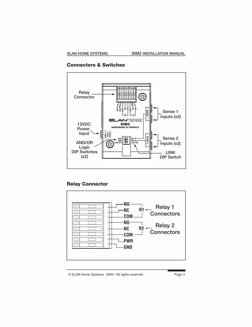
Sense 1Inputs (x2)
AND/ORLogic
DIP Switches(x2)
12VDCPower Input
LINKDIP Switch
RelayConnector
Sense 2Inputs (x2)
Relay 1Connectors
Relay 2Connectors
Relay Connector
Connectors & Switches
Page 4 © ELAN Home Systems 2006 • All rights reserved.
SIM2 INSTALLATION MANUAL ELAN HOME SYSTEMS
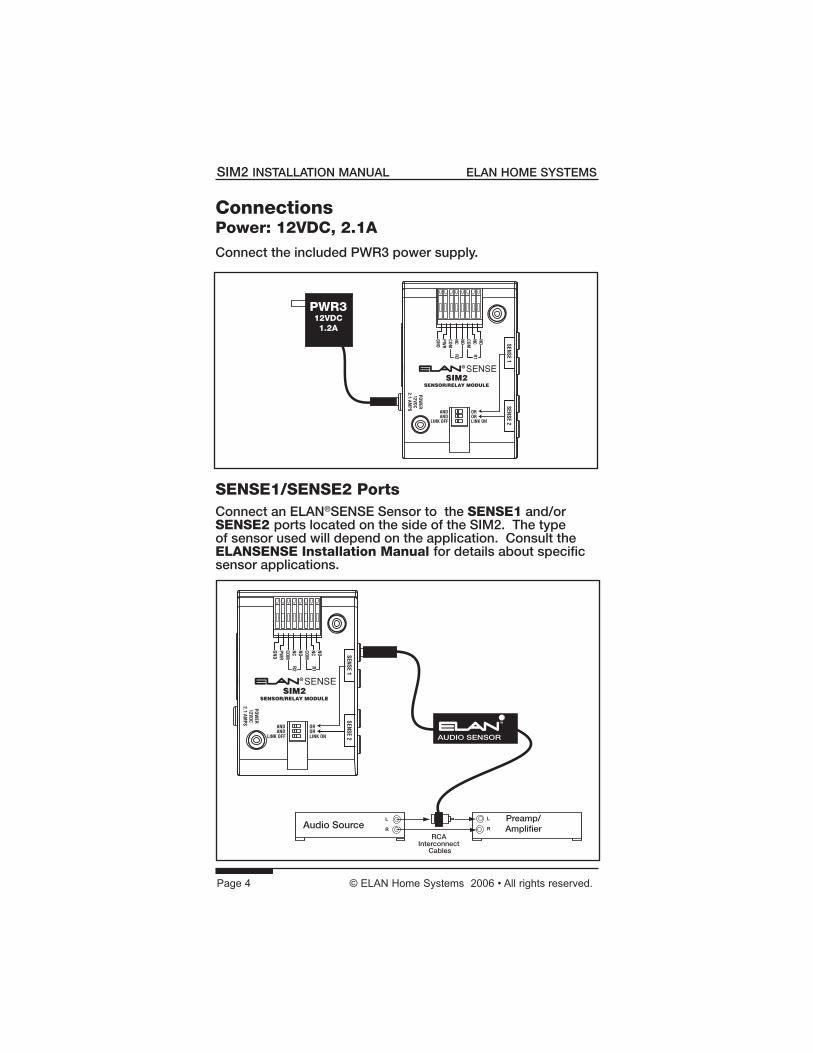
ConnectionsPower: 12VDC, 2.1A
Connect the included PWR3 power supply.
SENSE1/SENSE2 PortsConnect an ELAN®SENSE Sensor to the SENSE1 and/or SENSE2 ports located on the side of the SIM2. The type of sensor used will depend on the application. Consult the ELANSENSE Installation Manual for details about specific sensor applications.
L
R
L
R
Preamp/Amplifier
RCA Interconnect
Cables
AUDIO SENSOR
Audio Source
PWR312VDC1.2A
© ELAN Home Systems 2006 • All rights reserved. Page 5
ELAN HOME SYSTEMS SIM2 INSTALLATION MANUAL
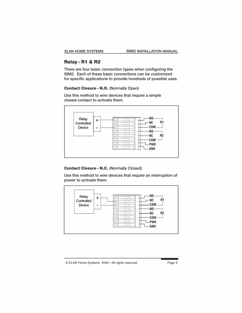
Relay - R1 & R2
There are four basic connection types when confi guring the SIM2. Each of these basic connections can be customized for specifi c applications to provide hundreds of possible uses.
Contact Closure - N.O. (Normally Open)
Use this method to wire devices that require a simple closed-contact to activate them.
Contact Closure - N.C. (Normally Closed)
Use this method to wire devices that require an interruption of power to activate them.
-
+RelayControlled
Device
-
+RelayControlled
Device
Page 6 © ELAN Home Systems 2006 • All rights reserved.
SIM2 INSTALLATION MANUAL ELAN HOME SYSTEMS
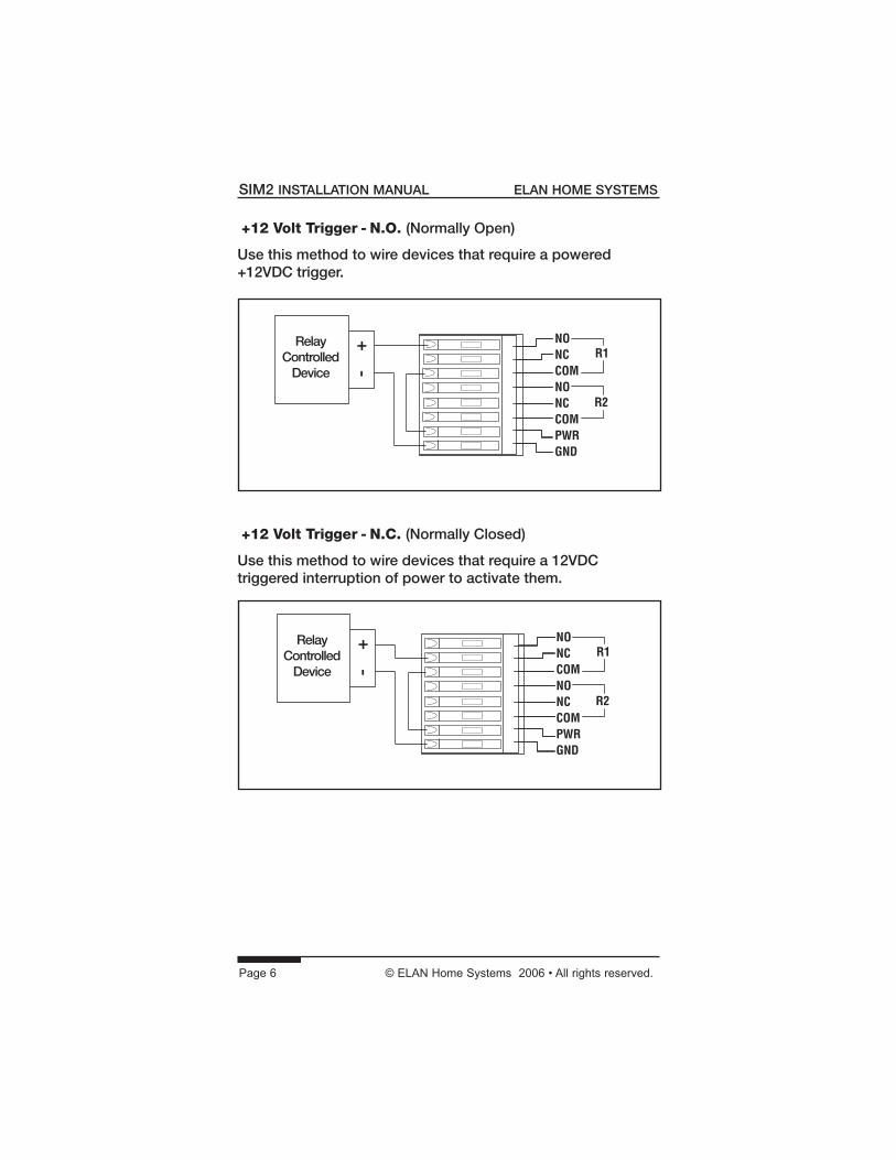
+12 Volt Trigger - N.O. (Normally Open)
Use this method to wire devices that require a powered +12VDC trigger.
-
+RelayControlled
Device
+12 Volt Trigger - N.C. (Normally Closed)
Use this method to wire devices that require a 12VDC triggered interruption of power to activate them.
-
+RelayControlled
Device
© ELAN Home Systems 2006 • All rights reserved. Page 7
ELAN HOME SYSTEMS SIM2 INSTALLATION MANUAL
DIP Switch SettingsThere are two DIP switches on the SIM2 that provideAND/OR logic functionality for each pair of Sense Inputs, and one DIP switch that links the two Relay Outputs.
AND/OR Logic DIP Switches
Each Sense Input (SENSE1 and SENSE2) has two ports. If a single sensor is connected to a Sense Input, select OR for that input. If a sensor is connected to both ports of a Sense Input, use the AND/OR DIP switch to determine the function-ality as follows:
• AND - Relay will trip only if both of the connected sensors are active.
• OR - Relay will trip if either of the connected sensors is active.
LINK OFF/LINK ON Switch
The LINK OFF/LINK ON DIP switch links the two Relay Out-puts (R1 & R2). If the switch is set to LINK OFF, the sensors connected to SENSE1 control Relay 1 and the sensors con-nected to SENSE2 control Relay 2. If the switch is set to LINK ON, either Sense Input will trigger both R1 and R2. The AND/OR DIP switches determine whether one or both individual inputs of SENSE1 or SENSE2 activate the relay(s). Examples:
• SENSE1/R1/LINK OFF AND - R1 active if BOTH connected sensors are active OR - R1 active if EITHER connected sensor is active
• SENSE2/R2/LINK OFF AND - R2 active if BOTH connected sensors are active OR - R2 active if EITHER connected sensor is active
• SENSE1/LINK ON AND - R1 & R2 active if BOTH connected sensors are active OR - R1 & R2 active if EITHER connected sensor is active
• SENSE2/LINK ON AND - R1 & R2 active if BOTH connected sensors are active OR - R1 & R2 active if EITHER connected sensor is active
Page 8 © ELAN Home Systems 2006 • All rights reserved.
SIM2 INSTALLATION MANUAL ELAN HOME SYSTEMS
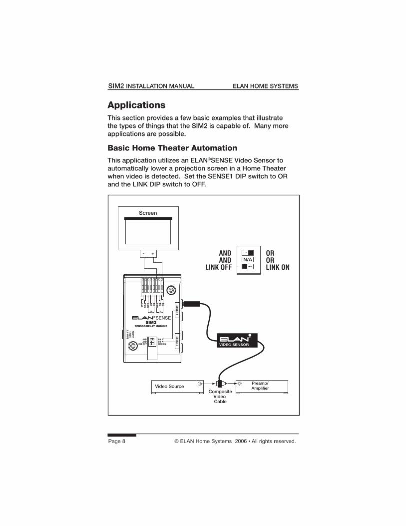
ApplicationsThis section provides a few basic examples that illustrate the types of things that the SIM2 is capable of. Many more applications are possible.
Basic Home Theater Automation This application utilizes an ELAN®SENSE Video Sensor to automatically lower a projection screen in a Home Theater when video is detected. Set the SENSE1 DIP switch to OR and the LINK DIP switch to OFF.
Screen
- +
Preamp/Amplifier
CompositeVideo Cable
VIDEO SENSOR
Video Source
N/A
© ELAN Home Systems 2006 • All rights reserved. Page 9
ELAN HOME SYSTEMS SIM2 INSTALLATION MANUAL
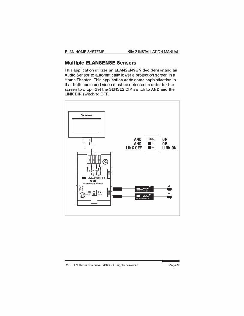
Multiple ELANSENSE Sensors This application utilizes an ELANSENSE Video Sensor and an Audio Sensor to automatically lower a projection screen in a Home Theater. This application adds some sophistication in that both audio and video must be detected in order for the screen to drop. Set the SENSE2 DIP switch to AND and the LINK DIP switch to OFF.
Screen
- +
AUDIO SENSOR
VIDEO SENSOR
N/A
Page 10 © ELAN Home Systems 2006 • All rights reserved.
SIM2 INSTALLATION MANUAL ELAN HOME SYSTEMS
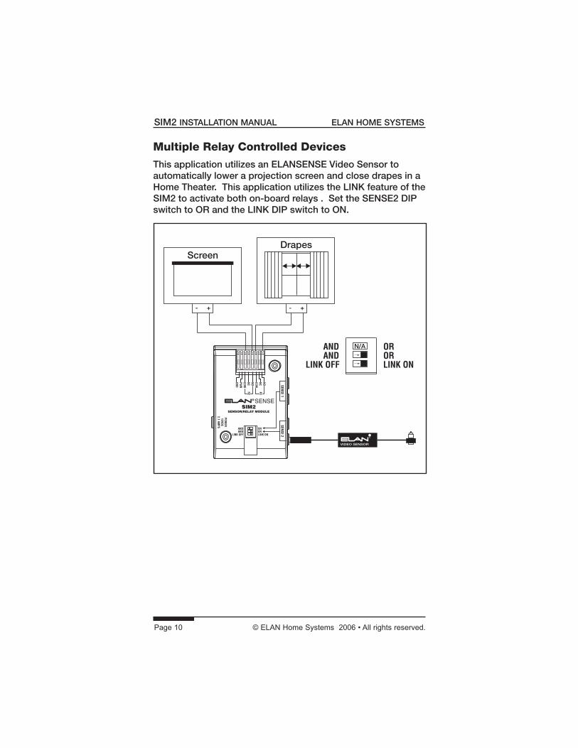
Multiple Relay Controlled Devices This application utilizes an ELANSENSE Video Sensor to automatically lower a projection screen and close drapes in a Home Theater. This application utilizes the LINK feature of the SIM2 to activate both on-board relays . Set the SENSE2 DIP switch to OR and the LINK DIP switch to ON.
Screen
- +
VIDEO SENSOR
Drapes
- +
N/A
© ELAN Home Systems 2006 • All rights reserved. Page 11
ELAN HOME SYSTEMS SIM2 INSTALLATION MANUAL
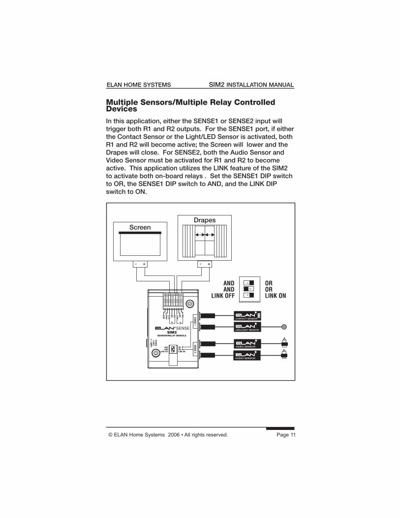
Multiple Sensors/Multiple Relay Controlled Devices In this application, either the SENSE1 or SENSE2 input will trigger both R1 and R2 outputs. For the SENSE1 port, if either the Contact Sensor or the Light/LED Sensor is activated, both R1 and R2 will become active; the Screen will lower and the Drapes will close. For SENSE2, both the Audio Sensor and Video Sensor must be activated for R1 and R2 to become active. This application utilizes the LINK feature of the SIM2 to activate both on-board relays . Set the SENSE1 DIP switch to OR, the SENSE1 DIP switch to AND, and the LINK DIP switch to ON.
Screen
- +
AUDIO SENSOR
Drapes
- +
VIDEO SENSOR
LED/LIGHT SENSOR
CONTACT SENSOR
Page 12 © ELAN Home Systems 2006 • All rights reserved.
SIM2 INSTALLATION MANUAL ELAN HOME SYSTEMS
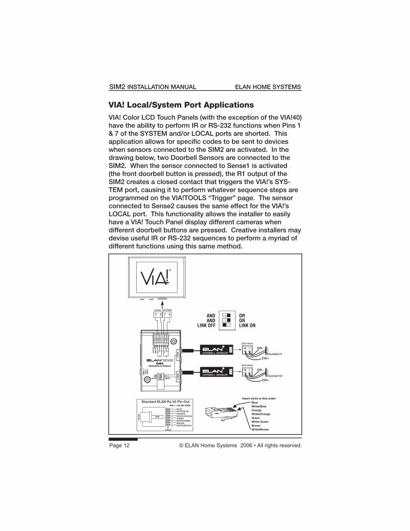
VIA! Local/System Port Applications
VIA! Color LCD Touch Panels (with the exception of the VIA!40) have the ability to perform IR or RS-232 functions when Pins 1 & 7 of the SYSTEM and/or LOCAL ports are shorted. This application allows for specific codes to be sent to devices when sensors connected to the SIM2 are activated. In the drawing below, two Doorbell Sensors are connected to the SIM2. When the sensor connected to Sense1 is activated (the front doorbell button is pressed), the R1 output of the SIM2 creates a closed contact that triggers the VIA!’s SYS-TEM port, causing it to perform whatever sequence steps are programmed on the VIA!TOOLS “Trigger” page. The sensor connected to Sense2 causes the same effect for the VIA!’s LOCAL port. This functionality allows the installer to easily have a VIA! Touch Panel display different cameras when different doorbell buttons are pressed. Creative installers may devise useful IR or RS-232 sequences to perform a myriad of different functions using this same method.
+ -Doorbell #1
(End View)
DORBELL SENSOR
DB-
DB+
+ -Doorbell #2
(End View)
DORBELL SENSOR
DB-
DB+
Insert wires in this order:BlueWhite/BlueOrangeWhite/OrangeGreenWhite GreenBrownWhite/Brown
BLUEWHITE/BLUEORANGEWHITE/ORANGEGREENWHITE/GREENBROWNWHITE/BROWN
12345678
PIN # COLOR CODE
FR
ON
T
CABLE
Standard ELAN RJ-45 Pin-Out
TAB
SYSLOC
SYSTEMLOCAL
17 17


Limited WarrantyELAN HOME SYSTEMS L.L.C. (“ELAN”) warrants the SIM2 Sensor Integration Module to be free from defects in materials and workman-ship for the period of two years (2 years) from date of purchase. If within the applicable warranty period above purchaser discovers that such item was not as warranted above and promptly notifi es ELAN in writing, ELAN shall repair or replace the item at the company’s option. This warranty shall not apply (a) to equipment not manufactured by ELAN, (b) to equipment which shall have been installed by other than an ELAN authorized installer, (c) to installed equipment which is not installed to ELAN’s specifi cations, (d) to equipment which shall have been repaired or altered by others than ELAN, (e) to equipment which shall have been subjected to negligence, accident, or damage by circumstances beyond ELAN’s control, including, but not limited to, lightning, fl ood, electrical surge, tornado, earthquake, or other catastrophic events beyond ELAN’s control, or to improper operation, maintenance or storage, or to other than normal use of service. With respect to equipment sold by, but not manufactured by ELAN, the warranty obligations of ELAN shall in all respects conform to the warranty actually extended to ELAN by its sup-plier. The foregoing warranties do not cover reimbursement for labor, transportation, removal, installation or other expenses which may be incurred in connection with repair or replacement.
Except as may be expressly provided and authorized in writing by ELAN, ELAN shall not be subject to any other obligations or liabilities what-soever with respect to equipment manufactured by ELAN or services rendered by ELAN.
THE FOREGOING WARRANTIES ARE EXCLUSIVE AND IN LIEU OF ALL OTHER EXPRESSED AND IMPLIED WARRANTIES EXCEPT WARRAN-TIES OF TITLE, INCLUDING BUT NOT LIMITED TO IMPLIED WAR-RANTIES OF MERCHANTABILITY AND FITNESS FOR A PARTICULAR PURPOSE.
ATTENTION: TO OUR VALUED CONSUMERSTo ensure that consumers obtain quality pre-sale and after-sale support and service, ELAN Home Systems products are sold exclusively through authorized dealers. ELAN products are not sold online. The warranties on ELAN products are NOT VALID if the products have been purchased from an unauthorized dealer or an online E-tailer. To determine if your ELAN reseller is authorized, please call ELAN Home Systems at (859) 269-7760.
P/N 9900783 REV:B