sensor for monitoring the moisture in porous materials
TRANSCRIPT
Int J ThermophysDOI 10.1007/s10765-013-1493-0
Sensor for Monitoring the Moisture in Porous Materials
D. Fidríková · V. Vretenár · I. Šimková ·V. Greif · J. Vlcko · P. Dieška · L’. Kubicár
Received: 20 August 2012 / Accepted: 29 July 2013© Springer Science+Business Media New York 2013
Abstract A new principle of a sensor for monitoring of moisture in porous materials ispresented. The sensor utilizes changes of the thermal conductivity of a porous structurewhen pores are filled with the air/vapor, water, or ice depending on thermodynamicconditions. A hot-ball method is used for measuring the thermal conductivity. Themoisture sensor is made of the cylindrical core drilled from the parent material. Thesignal of the sensor is not sensitive to ionic radicals of the pore medium. The methodof sensor calibration is presented, as well. Then the moisture sensor (hot ball) isinserted back into the drilled hole of the material to ensure that the porous structureof both the sensor and the investigated material are identical. Sensors can be made ofporous materials in the range of porosities from 0.3 % up to 70 %. A simple device isconstructed that allows monitoring of moisture in real conditions.
Keywords Hot-ball method · Moisture sensor · Porous materials ·Thermal conductivity
D. Fidríková · V. Vretenár · L’. Kubicár (B)Institute of Physics SAS, Dúbravska Cesta 9,845 11 Bratislava , Slovakiae-mail: [email protected]
I. Šimková · V. Greif · J. VlckoDepartment of Engineering Geology, Faculty of Natural Sciences, Comenius University,Mlynská dolina G, 842 15 Bratislava 4, Slovakia
P. DieškaInstitute of Nuclear Science and Physical Engineering, Faculty of Electrical Engineering,STU, Ilkovicova 3, 812 19 Bratislava, Slovakia
123

Int J Thermophys
1 Introduction
Buildings are constructed from construction materials with a porous structure. Suchobjects, in real environments, are attacked by atmospheric moisture, precipitation, andgroundwater [1]. The absorption and transport of water in porous materials, perhapsalso combined with the effects of air/vapor movement through foundations and build-ing walls within various types of structures, are complex processes. Moisture in thewalls has a destructive deterioration effect that is caused by natural or human-inducedcycles of drying—wetting and freezing—thawing. Modern building technology cansignificantly suppress the diffusion of moisture into any type of structure. The sup-pression of moisture in historic buildings requires protective measures. However, thereremains an open question related to the effectiveness of the available measures. Thisquestion can be answered by appropriate moisture monitoring, e.g., [2]. Therefore, theissue of moisture monitoring has recently assumed a high priority in materials science.
The measurement of moisture in porous materials uses sensors based on differentprinciples. Most sensors are based on electrical or electromagnetic principles [3–5]. Electrical properties of materials can be very sensitive to the presence of water;however, measurement reliability is limited by a set of factors such as electrical contactsof a sensor with the porous structure, the presence of dissolved salts in the poresolution, etc. Techniques give comparative data, but without further calibration, theycannot give accurate absolute data. Commercial devices are often calibrated to give anabsolute moisture content reading for a particular material. Microwave moisture metersof various constructions are available which measure the dielectric constant of themedium in contact with the sensor. However, the presence of metallic components andcertain ionic radicals within the measured volume can give misleading results. A moresophisticated technique, time domain reflectometry (TDR), relies on the fundamentalphysical principle of the propagation of electromagnetic signals along a waveguide [6].The signal velocity is related to the dielectric constant of the surrounding media thatis influenced by moisture content. Calibration can be achieved through comparativemeasurements of the sensors in liquids with well defined dielectric properties. Thistechnique measures the average moisture content along the length of the waveguide thatis inserted in a hole drilled into the porous structure. A set of limiting factors reduces themeasurement accuracy. The sensor signal is strongly influenced by chemical radicalsin the media pores. Recently, thermophysical sensors have been developed, which dueto their appropriate design, can be used in a monitoring mode. Sensors operating onthe principle of the thermal field are not affected by chemical radicals in media [7].The dual-probe heat-pulse method (DPHPM) is among the candidates for monitoringof moisture in a porous structure. Unlike electrical and electromagnetic methods, thismethod is not sensitive to ionic radicals. The signal of the DPHPM method is correlatedwith the heat capacity of the tested material, which for a water-saturated structure issignificantly higher due to the high heat capacity of water, 4187 J · kg−1 · K−1. Thesensor is shaped in the form of a needle.
This paper discusses the design of a moisture sensor based on the principle ofmeasuring the thermal conductivity of porous structures. The hot-ball method formeasuring the thermal conductivity is used. Briefly, the theory of the hot-ball methodis discussed and construction and calibration of the moisture sensor is described.
123

Int J Thermophys
2 Principle of Moisture Sensor
The principle of the moisture sensor is based on the measurement of the thermalconductivity of porous media. The thermal conductivity of porous media is a functionof the matrix and the pore content. Figure 1 shows differences in thermal conductivityof a broad range of materials for dry and water-saturated conditions. Materials includeporous structures with a porosity in the range from 0.3 % up to 70 %. The changesin thermal conductivity are considerable. It should be noted that additional effectsinfluence the value of the thermal conductivity for a low porosity [8].
In a real environment, the pores can be filled with air/vapor, water, or ice, depend-ing on the thermodynamic state. Table 1 gives the basic characteristics of the abovementioned media. The data in the table show the wide range of thermal-conductivityvalues.
Generally, a porous structure is composed of several components. A schematicdiagram of a porous structure is shown in Fig. 2a while a detailed configuration of thecomponents is shown in Fig. 2b. We limit our consideration to two main components,the matrix and pores. Then the resulting thermal conductivity is designated as theeffective thermal conductivity. Experimentally, the effective thermal conductivity ofsuch a structure is determined by direct measurement. Estimation of the expectedchanges in the effective thermal conductivity due to the presence of moisture can
-10 0 10 20 30 40 50 60 70 800.1
1
AA
C [
21]
San
der
San
dsto
ne [1
7]
Vin
cenz
ea A
rcar
i [20
]
Mar
ble
Gio
ia [8
] saturated dry
The
rmal
con
duct
ivity
, W⋅m
-1⋅K
-1
Porosity, %
Fig. 1 Thermal conductivity of a range of porous structures for dry and water-saturated conditions. Auto-claved aerated concrete (AAC) is saturated to 20 %
Table 1 Basic thermophysical characteristics of media in pores [18]
Parameter Air-dry Water Ice
Thermal diffusivity (10−6 m2 · s−1) 27 0.14 1.18Thermal conductivity (W · m−1 · K−1) 0.025 0.59 2.22Specific heat (J · kg−1 · K−1) 1005 4226 2050Density (kg · m−3) 1.29 1000 920
123

Int J Thermophys
(a) (b)
liquid
solid
phaseboundary gas
Fig. 2 (a) Schematic diagram of the porous structure together with percolation paths and (b) details of theinner structure of the pore
be carried out using appropriate models. The Maxwell model for a two-componentsystem has the form [9],
λeff = λ2 [2λ2 + λ1 − 2w1 (λ2 − λ1)]
2λ2 + λ1 + w1 (λ2 − λ1)(1)
and the Babanov model [10],
λeff =λ2
[λ2 + w
2/31 (λ1 − λ2)
]
λ2 + w2/31 (λ1 − λ2)
(1 − w
1/31
) (2)
where λeff is the effective thermal conductivity, λ1 is the thermal conductivity of thepore content, λ2 is the thermal conductivity of the matrix, and w1 is the porosity. Bothmodels are tested for porous structures as shown in Fig. 2. Reliability of the modelsis tested by the calculation of the thermal conductivity of the matrix component.Input data are the effective thermal conductivity measured for dry conditions and theporosity (Table 2). The difference in the thermal conductivity of the matrix betweenmodels increases with increasing porosity. The calculated data of the effective thermalconductivity for materials with water or ice present in the pores are given in Table 2.These data were calculated using Eqs. 1 and 2 and the mean values of the thermalconductivities of the matrix given by both models. The largest deviation between thecalculated effective thermal conductivities (see Table 2) and measured values (Fig. 1)was found for AAC. Experimentally, the effective thermal conductivity of AAC wasdetermined for 20 % saturation only. Calculated data correspond theoretically to fullsaturation of the tested specimen.
Generally data on the effective thermal conductivity of commercially purchasedporous materials can be found in the data sheets given by producers. Then it is easyto estimate changes in the effective thermal conductivity using the above describedprocedure for water-saturated condition. This estimation helps us in design of the elec-tronic devices considering changes in measuring signals. The hot-ball method is usedfor measuring the thermal conductivity [11]. It should be stressed that functionalityof the moisture sensor needs an open porous structure. The working regime of themoisture sensor depends on the appropriate design of the hot-ball sensing element. Itstheory and technical realization will be described in the next paragraph.
123
Int J Thermophys
Table 2 Measured and calculated data of thermal conductivity (W · m−1 · K−1) in used for estimation ofthe role of porous media in different materials
Material Porosity(%)
Measuredin dry airλeff
Dry air Water Ice
Babanov Maxwell Babanov Maxwell Babanov Maxwellλmatrix λmatrix λeff λeff λeff λeff
Marble Gioia 0.3 2.25 2.32 2.35 2.27 2.26 2.33 2.33
Sander Sandstone 17 1.89 2.35 2.45 2.06 2.01 2.37 2.37
Arcari Vincezea 27 1.1 1.62 1.7 1.34 1.32 1.81 1.8
AAC 70 0.126 0.32 0.46 0.524 0.523 1.31 1.26
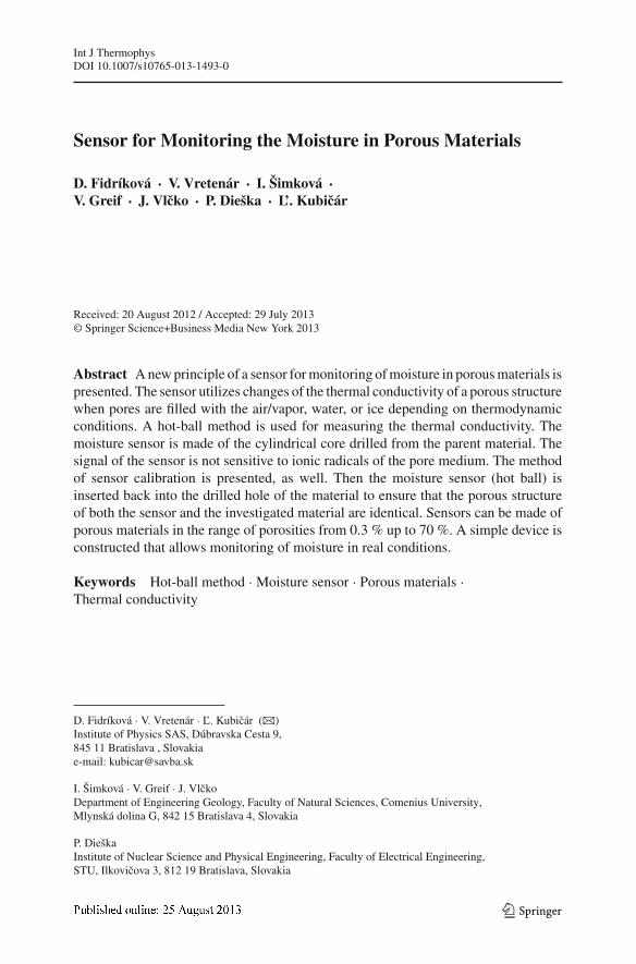
3 Theory of the Hot-Ball Method
Optimal functionality of the moisture sensor depends on an appropriate method formeasuring the thermal conductivity of a body constructed of porous materials. Weuse the hot-ball method for measuring thermophysical properties. The method makesuse of a small ball that generates a transient temperature field in its vicinity andsimultaneously measures the temperature. The ball temperature is a measure of thethermal conductivity of the surrounding material.
Different models can be employed for description of the hot-ball method. All mod-els give the same working equation in the long time span. Here we present a modelthat exploits a negligible heat capacity of the ball—the model of the empty sphere[11]. A sketch of an embedded hot-ball sensor is shown in Fig. 3a. A heat source inthe form of a small ball starts to produce heat with a constant rate and simultaneouslymeasures the temperature response of the surrounding medium (Fig. 3b). The tem-perature response stabilizes at a constant value Tm over time. Tm is used to determinethe thermal conductivity of the surrounding medium. Heat penetrates to a sphere withradius R during the temperature stabilization to Tm. Thus, the determined thermalconductivity corresponds to the material property within the sphere.
(a) (b) Time
Tem
pera
ture
Tm
rb R
Fig. 3 (a) Model of the hot-ball and (b) temperature response for constant production of heat q0 = constfor t > 0. Black region hot-ball area, gray region area penetrated by heat
123

Int J Thermophys
The working equation of the hot-ball sensor is based on a model, which assumes aconstant heat flux q0 from the surface of the ball of radius rb into the infinite medium.Then for the negligible heat capacity and high thermal conductivity of the ball, thetemperature distribution within the medium is characterized by the function [12],
T (r, t) = q0
4πλr
[erfc
(r − rb
2√
at
)− exp
(r − rb
rb+ at
r2b
)× erfc
(r − rb
2√
at+
√at
r
)]
(3)
erfc (x) = 1 − 2√π
x∫
0
exp(−ζ 2
)dζ (4)
where erfc(x) is the complementary error function defined by Eq. 4 and λ and a are thethermal conductivity and thermal diffusivity of the surrounding medium, respectively.Equation 3 is a solution of the partial differential equation for heat conduction forr ≥ rb considering the following boundary and initial conditions:
−λ∂T (r, t)
∂r= q0
4πr2b
1(t), for r = rb
T (r, t) = 0, T (r, 0) = 0 for r → ∞
where 1(t) is a unit step function. Then for long times (t → ∞), and r = rb, the
first term in brackets on the right-hand side in Eq. 3 tends to erfc(
r−rb2√
at
)→ 1 and
the second term on the right-hand side to exp
(r−rb
rb+ at
r2b
)× erfc
(r−rb2√
at
)→ 0. One
obtains the following working equation of the measuring method:
λ = q0
4πrbTm(5)
where Tm is the stabilized value of the temperature response at r = rb (Fig. 3b). Thehollow sphere represents an ideal hot ball of radius rb.
The measuring method based on Eq. 5 belongs, in fact, to the class of transientmethods. However, the hot-ball method has two regimes: transient and steady state,using either Eq. 3 or 5, respectively. Heat sources of spherical symmetry possess aspecial feature, i.e., they yield the steady state in long time. In our case Eq. 5 is usedfor evaluation of the thermal conductivity.
3.1 Hot-Ball Construction
A hot-ball sensor is shown in Fig. 4a. The sensor has been constructed of two elements,a heater and a thermistor (patented). Both elements are fixed in the ball using epoxyresin. The diameter of the ball ranges from 1.8 mm to 2.3 mm. A simple instrumentRTM (Transient MS, s.r.o.) depicted in Fig. 4b was constructed that consists of a data
123

Int J Thermophys
(a) (b)
Hot-ball sensor
power source
A/D
D/A
µP + data logger
RS 232
Fig. 4 (a) Photo of hot-ball sensor and (b) schematic of the RTM instrument for monitoring thermalconductivity
logger, a microcontroller connected with an A/D converter for temperature measure-ment, and a D/A converter in connection with a current source for heat generation.The instrument can be pre-programmed over the USB channel by a PC. The device isconstructed for use in a harsh environment.
A typical measurement is shown in Fig. 5 along with characteristic points usedfor the calculation of the thermal conductivity. The measuring procedure consists ofthe specimen temperature measurement representing the baseline, switching on theheating and simultaneously scanning the ball temperature. When the ball temperaturestabilizes, the heating is interrupted and a period of temperature equilibration follows.When the temperature in the specimen is stabilized to the value prior to heat generation,the next measurement starts. The repeatability rate of the measurements depends onthe thermal conductivity, and it takes from 5 min up to several hundreds of minutes. Ameasurement itself takes from 50 s up to 400 s depending on the thermal conductivityof the investigated material. For rocks, it ranges from 80 s up to 150 s.
A set of disturbing factors influence measurement accuracy by the hot-ball method.Two of them are essential, namely, the connecting wires to the hot ball and the ther-mophysical properties of the ball material. Whereas the first factor affects the heatbalance of the hot ball [11,13], the second distorts the temperature reaction [11,14]. Itshould be noted that the evaluation of the measurement can be done using Eq. 5 or byfitting a suitable temperature function [14]. The latest version of the hot-ball design,which is based on a metallic ball with a diameter of 3 mm [15] achieves the followingaccuracies of the thermophysical parameters: thermal conductivity 3 %, thermal dif-fusivity 5 %, and specific heat 5 %. Quoted accuracies were achieved when measuringdistilled water ( λ = 0.58 W · m−1 · K−1) and glycerol (λ = 0.28 W · m−1 · K−1).It is assumed that the thermal contact resistance plays a mirror role for fluids duringmeasurements. However, the difference in measurements between the fluids and thesolids is in the contact thermal resistance that for solids always exists. As the hot ballis fixed in the moisture sensor body, the system hot ball and the surrounding body arecalibrated for dry and water-saturated conditions to avoid the negative influence of thedisturbing factors.
4 Moisture Sensor
The moisture sensor is composed of a cylindrical body with a diameter and lengtharound 20 mm corresponding to the parent porous material. A hole with a diameter of2 mm is drilled in the axis of the cylinder, where the hot ball is inserted and fixed by
123

Int J Thermophys
-20 0 20 40 60 80 100 120 14020.8
21.0
21.2
21.4
21.6
21.8
22.0
0
2
4
6
8
10
12
14
16
Tm
temperature response
Out
put p
ower
, mW
Tem
pera
ture
, o C
Time, s
base line
output power
Fig. 5 Measurement signal (empty circle) and heat output of the hot ball (red line) (Color figure online)
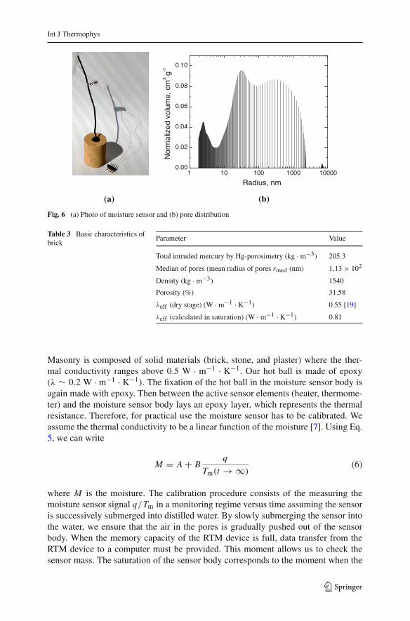
epoxy resin. Minimum dimensions of the moisture sensor are given by the penetrationdepth. The penetration depth is determined by the time needed to stabilize the signalto a value of Tm, i.e., dimensions of the sensor must be such that the transport of heatgenerated by the hot ball is not affected by the surfaces of the body sensor (Fig. 3a),and so the hot ball must work in an infinite medium [16]. The moisture sensor is shownin Fig. 6a.
The sensor body is made from a core taken from the borehole drilled in the porousmaterial in which the moisture will be monitored. The core drill inserted back in theborehole exactly at the same position ensures that the properties of the sensor andthe porous material are identical. In our case a porous material is represented by abrick. The porous structure of the sensor body was analyzed by mercury porosimetry.Figure 6b shows the pore size distribution. Basic characteristics of the porous structureare given in Table 3. The distribution has several peaks around 4 nm, 32 nm, and368 nm.
Using Eq. 1, we determined the thermal conductivity of the matrix λ2 (0.92 W ·m−1 · K−1) and then the effective thermal conductivity of the water-saturated brick(0.81 W · m−1 · K−1) is calculated by the procedure described in Sect. 2. Then thedifference between the dry and saturated stages gives the possible range of the sensorsignal changes. For temperatures below zero, the transition effect of freezing/meltingcan be recorded by the sensor due to latent heat [17].
4.1 Calibration of the Moisture Sensor
The accuracy of the thermal conductivity is limited by many factors [11,13,14]. More-over, the theory of the method assumes the form of a hot ball to be an ideal emptysphere. The real hot ball is different in shape and ball material (see Figs. 3a, 4a). Ameasurement uncertainty of the thermal conductivity of approximately 3 % can beattained for fluids when its thermal conductivity is below 0.5 W · m−1 · K−1 [11,15].
123
Int J Thermophys
1 10 100 1000 100000.00
0.02
0.04
0.06
0.08
0.10
Nor
mal
ized
vol
ume,
cm
3 ⋅g-1
Radius, nm
(a) (b)
Fig. 6 (a) Photo of moisture sensor and (b) pore distribution
Table 3 Basic characteristics ofbrick
Parameter Value
Total intruded mercury by Hg-porosimetry (kg · m−3) 205.3
Median of pores (mean radius of pores rmed (nm) 1.13 × 10²
Density (kg · m−3) 1540
Porosity (%) 31.58
λeff (dry stage) (W · m−1 · K−1) 0.55 [19]
λeff (calculated in saturation) (W · m−1 · K−1) 0.81
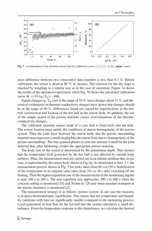
Masonry is composed of solid materials (brick, stone, and plaster) where the ther-mal conductivity ranges above 0.5 W · m−1 · K−1. Our hot ball is made of epoxy(λ ∼ 0.2 W · m−1 · K−1). The fixation of the hot ball in the moisture sensor body isagain made with epoxy. Then between the active sensor elements (heater, thermome-ter) and the moisture sensor body lays an epoxy layer, which represents the thermalresistance. Therefore, for practical use the moisture sensor has to be calibrated. Weassume the thermal conductivity to be a linear function of the moisture [7]. Using Eq.5, we can write
M = A + Bq
Tm(t → ∞)(6)
where M is the moisture. The calibration procedure consists of the measuring themoisture sensor signal q/Tm in a monitoring regime versus time assuming the sensoris successively submerged into distilled water. By slowly submerging the sensor intothe water, we ensure that the air in the pores is gradually pushed out of the sensorbody. When the memory capacity of the RTM device is full, data transfer from theRTM device to a computer must be provided. This moment allows us to check thesensor mass. The saturation of the sensor body corresponds to the moment when the
123
Int J Thermophys
7.8
8.0
8.2
8.4
8.6
8.8
9.0
9.2
9.4
Water saturated
Dry
Mas
s, g
q/T m
, J⋅K
-1
Time, h
21
22
23
24
25
26
0 20 40 60 80 7.8 8.0 8.2 8.4 8.6 8.8
0
20
40
60
80
100
Moi
stur
e, %
q/Tm, J⋅K-1
(a) (b)
Fig. 7 (a) Saturation of the moisture sensor and (b) calibration curve, © © ©—q/Tm, ���—mass
mass difference between two consecutive data transfers is less than 0.1 %. Beforecalibration, the sensor is dried at 80 ◦C in vacuum. The criterion for the dry stage ischecked by weighing in a similar way as in the case of saturation. Figure 7a showsthe results of the saturation experiment, while Fig. 7b shows the calculated calibrationcurve M =119·(q/Tm) − 946.
Signal changes (q/Tm) are in the range of 10 %, mass changes about 21 %, and the-oretical estimations on thermal-conductivity changes have shown that changes shouldbe in the range of 40 %. Differences found are caused by imperfections in the hot-ball construction and fixation of the hot ball in the sensor body. In addition, the useof the simple model of the porous structure causes overestimations of the thermal-conductivity changes.
The calibrated moisture sensor made of a core drill is fixed back into the hole.The sensor fixation must satisfy the conditions of macro-homogeneity of the poroussystem. Then the joint layer between the sensor body and the porous surroundingmaterial must represent a small (negligible) deviation from macro-homogeneity of theporous surroundings. The fine-grained plaster or concrete mixture is used for the jointmaterial that, after hardening, creates the appropriate porous structure.
The body size of the sensor is determined by the penetration depth. This ensuresthat the temperature field generated by the hot ball is not affected by outside bodysurfaces. Thus, the measurement runs are carried out in an infinite medium that, in ourcase, is represented by the sensor body shown in Fig. 6a. As mentioned in Sect. 3.1, themeasurement process shown in Fig. 5 for rocks takes from 80 s to 150 s. Stabilizationof the temperature to its original value takes from 10 s to 30 s after switching off theheating. Then the highest repetition rate of the measurements in the monitoring regimeis near 100 s to 200 s. The real repetition rate approaches 300 s to 600 s when theconcrete setting is monitored [15] and 30 min to 120 min when moisture transport inthe porous structures is monitored [2].
The measurement strategy is as follows: porous system, in our case the masonry,is in quasi-thermodynamic equilibrium. This means that the temperature and humid-ity variations with time are significantly smaller compared to the measuring process.Local generation of heat flow by the hot ball into the system introduces a small dis-turbance. From the temperature response to this disturbance, we calculate the thermal
123

Int J Thermophys
conductivity and the moisture of a porous system is established through calibration.Heat flow from the hot ball ranges from 10 mW to 20 mW into 4π space. The magni-tude of the corresponding temperature response (rise of the temperature at the sensorsurface) ranges from 1 K to 2 K during a time interval from 5 s to 10 s. Thus, thedisturbance quickly dies down. We say that the disturbance is well localized in spaceand time. Thus, the recorded information corresponds to local thermodynamic equi-librium.
The accuracy of the moisture determination is determined by the precision of thecalibration. In our case, we use a linear approximation M = a + bλ, where a and bare constants determined from the dry and water-saturated states. In the real case, thethermal conductivity may be a nonlinear function of moisture. Therefore, the extentof the nonlinearity contributes to the moisture error. Reducing the measuring rangeof the moisture sensor, i.e., from 30 % to 80 %, we can increase the accuracy of themoisture determination. The moisture range of 30 % to 80 % for our meteorologicalconditions is most common.
5 Conclusions
A new principle of a sensor for monitoring of moisture in porous materials is presented.The sensor utilizes changes of the thermal conductivity of a porous structure whenpores are filled by air/vapor, water, or ice, depending on thermodynamic conditions.A hot-ball method is used for measuring the thermal conductivity. The method isbased on a small ball that generates heat in a step-wise regime, and simultaneouslyit measures its temperature. The transport of heat from the ball into the surroundingporous material is a measure of the thermal conductivity. The output power of the hotball ranges up to 20 mW, and the temperature response ranges up to 2 K. The diameterof the hot-ball sensor itself is about 2 mm. The ball is inserted into the core drill takenfrom the porous material that is under investigation. The signal of the sensor is notsensitive to ionic radicals of the pore medium. The moisture sensor is calibrated for dryand water-saturated conditions. The sensors can be made of materials with porositiesranging from 0.3 % up to 70 %. A simple device is constructed that allows monitoringof the moisture in real conditions. Both the hot-ball sensor and the moisture sensors,manufactured from artificial (brick) or natural (rocks), have broad applications in theresearch of porous materials used in industry.
Acknowledgments Authors would like to express thanks to Mr. Markovic for technical assistance. Thework was supported by APVV grand agency under contracts LPP 0442-09, APVV 0641-10, and APVV0330-10.
References
1. R.J. Gummerson, C. Hall, W.D. Hoff, R. Hawkes, G.N. Holland, W.S. Moore, Nature 281, 56 (1979)2. L’. Kubicár, V. Vretenár, V. Štofanik, V. Bohác, P. Tiano, in Proceedings of the In situ Monitoring of
Monumental Surfaces—SMW08, ed. by P. Tiano (Florence, Italy, 2008), p. 533. S. Roels, J. Carmeliet, H. Hens, O. Adan, H. Brocken, R. Cerny, Z. Pavlik, A.T. Ellis, C. Hall, K.
Kumaran, L. Pel, R. Plagge, J. Therm. Envel. Build. Sci. 27, 307 (2004)4. M.C. Phillipson, P.H. Baker, M. Davies, Z. Ye, A. McNaughtan, G.H. Galbraith, R.C. McLean, Build.
Serv. Eng. Res. Technol. 28, 303 (2007)
123

Int J Thermophys
5. R.J. Ball, G.C. Allen, J. Phys. D Appl. Phys. 43, 1 (2010). doi:10.1088/0022-3727/43/10/1055036. M.C. Phillipson, P.H. Baker, M. Davies, Z. Ye, G.H. Galbraith, R.C. McLean, Build. Serv. Eng. Res.
Technol. 29, 261 (2008)7. G.S. Campbell, C. Calissendorff, J.H. Williams, Soil Sci. Soc. Am. J. 55, 291 (1991)8. V. Vretenár, L’. Kubicár, V. Bohác, P. Tiano, Int. J. Thermophys. 28, 1522 (2007)9. J.C.A. Maxwell, Treatise of Electricity and Magnetism, vol. 1, 3rd edn. (Clarendon Press, Oxford,
1904), p. 44010. A.A. Babanov, Sov. Phys. Technol. Phys. 2, 476 (1957)11. L’. Kubicár, V. Vretenár, V. Štofanik, V. Bohác, Int. J. Thermophys. 31, 1904 (2010)12. H.S. Carslaw, J.C. Jaeger, Conduction of Heat in Solids (Clarendon Press, Oxford, 1956)13. A.G. Ruiz, L’. Kubicár, V. Vretenár, in Proceedings of 17th International Meeting of the Thermophys-
ical Society, ed. by O. Zmeskal (Podkylava, Slovakia, 2012), p. 48, http://www.fch.vutbr.cz/lectures/thermophysics/2012/Proceedings.php
14. L’. Kubicár, U. Hammerschmidt, D. Fidriková, P. Dieška, V. Vretenár, in Proceedings of 17th Interna-tional Meeting of the Thermophysical Society, ed. by O. Zmeskal (Podkylava, Slovakia, 2012), p. 166,http://www.fch.vutbr.cz/lectures/thermophysics/2010/pdf/Thermophysics_2010_Proceedings.pdf
15. V. Vretenár, L’. Kubicár, V. Bohác, in Proceedings of 17th International Meeting of the ThermophysicalSociety, ed. by O. Zmeskal (Podkylava, Slovakia, 2012), p. 251, http://www.fch.vutbr.cz/lectures/thermophysics/2012/Proceedings.php
16. U. Hammerschmidt, in Proceedings of the Thirtieth International Thermal Conductivity Conference,and the Eigteenth Thermal Expansion Symposium, ed. by D.S. Gaal, P.S. Gaal (DEStech PublicationInc., Lancaster, PA, 2010), p. 258
17. L’. Kubicár, V. Vretenár, V. Bohác, P. Tiano, Int. J. Thermophys. 27, 200 (2006)18. Thermophysical properties water, air, ice. http://www.engineeringtoolbox.com19. O. Koronthalyová, P. Matiašovský, in Proceedings of 11th International Meeting of the Thermophysical
Society, ed. by J. Leja (STU, Bratislava, Slovakia, 2007), p. 100, http://www.tpl.fpv.ukf.sk/engl_vers/thermophys/2007/Paper14.pdf
20. “Effects of the Weathering on Stone Materials: Assessment of their Mechanical Durability (McDUR)”,Project MCDUR G6RD-CT2000-00266, ACOUTHERM GRD3-2001-60001, (European CommissionCommunity Research and Development Information Service (CORDIS), 2005), http://cordis.europa.eu/search/index.cfm?fuseaction=proj.document&PJ_RCN=5057857
21. “Thermophysical Analysis of Autoclaved Aerated Concrete,” Report Institute of Physics (Bratislava,Slovakia, 2008) [in Slovak]
123