sensaguard 18 mm plastic barrel unique coded installation ... · 18 mm plastic barrel unique coded...
TRANSCRIPT

SensaGuardTM
18 mm Plastic BarrelUnique Coded
Installation Instructions
Certifications
IMPORTANT:SAVE THESE INSTRUCTIONS FOR FUTURE USE
Note: Refer to Technical Specifications for Certification information and ratings.
PN-46045 10000054879 Ver 00 October 2009

Table of ContentsInstallation Instructions 3Warnings 3Technical Specification 3Operating Characteristics 3Outputs (internally fused) 3Environmental 3Protection 4Dimensions 4Mode of Operation 4
Status Indicators 4Mounting Information 4
Nut Torque Specification 4Minimum Distance Between Sensors 5
Misalignment Curve 5Wiring Diagram 5
Recommended Mating Cable 5Diagnostics 5Troubleshooting 6Application Wiring Examples 8List of Recommended Relays 12Maintenance 12Repair 12Declaration of Conformity 12
PN-46045 10000054879 Ver 00 October 2009
2 SensaGuardTM 18 mm Plastic Barrel Installation Instructions
ENGLISH: This instruction sheet is available in multiple languages at www.rockwellautomation.com/literature. Select publication language and type "SensaGuard" in the search field.
GERMAN: Dieses Instruktionsblatt kann in mehreren Sprachen unter www.rockwellautomation.com/literature gelesen werden. Bitte Ihre Sprache anwählen und "SensaGuard" im Suchfeld eintippen.
FRENCH: Ces instructions sont disponibles dans différentes langues à l'adresse suivante www.rockwellautomation.com/literature.Sélectionner la langue puis taper “SensaGuard” dans le champ de recherche.
ITALIAN: La presente scheda d'istruzione è disponibile in varie lingue sul sito www.rockwellautomation.com/literature. Selezionare la lingua desiderata e digitare "SensaGuard" nel campo di ricerca.
SPANISH: Puede encontrar esta hoja de instrucciones en varios idiomas en www.rockwellautomation.com/literature. Seleccione el idioma de publicación y escriba "SensaGuard" en el campo de búsqueda.
PORTUGUESE: Esta folha de instruções está disponível em várias línguas em www.rockwellautomation.com/literature.Seleccione a língua de publicação e entre com "SensaGuard" no espaço de busca.
POLISH: Ta kartka z instrukcjami jest dostepna w wielu jezykach na stronie: www.rockwellautomation.com/literatureWybierz jezyk publikacji i wpisz w polu poszukiwania "SensaGuard".
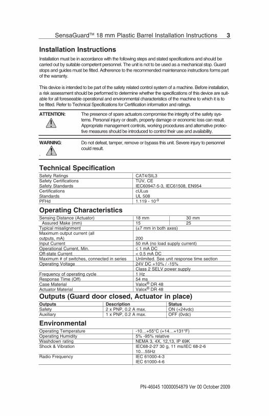
Installation InstructionsInstallation must be in accordance with the following steps and stated specifications and should becarried out by suitable competent personnel. The unit is not to be used as a mechanical stop. Guardstops and guides must be fitted. Adherence to the recommended maintenance instructions forms partof the warranty.
This device is intended to be part of the safety related control system of a machine. Before installation,a risk assessment should be performed to determine whether the specifications of this device are suit-able for all foreseeable operational and environmental characteristics of the machine to which it is tobe fitted. Refer to Technical Specifications for Certification information and ratings.
ATTENTION: The presence of spare actuators compromise the integrity of the safety sys-tems. Personal injury or death, property damage or economic loss can result.Appropriate management controls, working procedures and alternative protec-tive measures should be introduced to control their use and availability.
WARNING: Do not defeat, tamper, remove or bypass this unit. Severe injury to personnelcould result.
.
Technical SpecificationSafety Ratings CAT4/SIL3Safety Certifications TÜV, CESafety Standards IEC60947-5-3, IEC61508, EN954Certifications cULusStandards UL 508PFHd 1.119 - 10-9
Operating CharacteristicsSensing Distance (Actuator) 18 mm 30 mm
Assured Make (mm) 15 25Typical misalignment (±7 mm in both axes)Maximum output current (alloutputs, mA) 200Input Current 50 mA (no load supply current)Operational Current, Min. ≤ 1 mA DCOff-state Current < 0.5 mA DCMaximum # of switches, connected in series Unlimited. See unit response time section Operating Voltage 24V DC +10% / -15%
Class 2 SELV power supplyFrequency of operating cycle 1 HzResponse Time (Off) 54 msCase Material Valox® DR 48Actuator Material Valox® DR 48
Outputs (Guard door closed, Actuator in place)Outputs Description StatusSafety 2 x PNP, 0.2 A max. ON (+24vdc)Auxiliary 1 x PNP, 0.2 A max. OFF (0vdc)
EnvironmentalOperating Temperature -10…+55°C (+14…+131°F)Operating Humidity 5% -95% relativeWashdown rating NEMA 3, 4X, 12,13, IP 69KShock & Vibration IEC68-2-27 30 g, 11 ms/IEC 68-2-6
10…55HzRadio Frequency IEC 61000-4-3
IEC 61000-4-6
PN-46045 10000054879 Ver 00 October 2009
SensaGuardTM 18 mm Plastic Barrel Installation Instructions 3

ProtectionShort-Circuit Protection IncorporatedCurrent limitation IncorporatedOverload Protection IncorporatedFalse Pulse Protection IncorporatedTransient Noise Protection IncorporatedReverse Polarity Protection IncorporatedOvervoltage protection IncorporatedThermal shutdown/restart IncorporatedElectrical Life 10 x 106
Dimensions - mm (inches)
Mode of OperationStatus indicators:• “Power/Fault” LED illuminates Green - The unit is ready for operation.• “Power/Fault” LED illuminates Red: - Door/Guard open. The unit is not ready for operation.• “Power/Fault” LED illuminates flashes Red or Green: - Unit failure. See Diagnostic section below.
Mounting Information
Use non-removable screws, bolts, or nuts to mount the switch andactuator. Do not over torque the mounting hardware.
Position the switch and actuator so they are aligned with each other.
Mount the switch and actuator to removable guard, door or gate.Keep the switch and actuator within the sensing range below.
Nut Torque Specification
Plastic Barrel Switch: 2.26 N•M (20 in•lbs)Plastic Actuators: 2.26 N•M (20 in•lbs)
PN-46045 10000054879 Ver 00 October 2009
4 SensaGuardTM 18 mm Plastic Barrel Installation Instructions
30 mm Actuator
48.92[1.926]
19.81[0.78]
22.22[0.875]
48.92[1.926]
19.81[0.78]
22.22[0.875]
30.40[1.197]
16.84[0.663]
3.17[0.125]
4.57[0.18] DIA
2 PLACES
Sensor18 mm Actuator
67.06[2.640]2.03
[.080]
M18X1
36.47[1.436]
13.72[0.54] 15.87
[0.625]
36.47[1.436]
13.72[0.54]
15.87[0.625]
4.57[0.180] DIA
19.81[0.78]
3.17[0.125]
15.42[0.607]
2 PLACES

Minimum Distance Between Sensors
Misalignment Curve
18 mm Unit with 18 mm Target 18 mm Unit with 30 mm Target
Note: There must be a minimum spacing of 4 mm(0.157 in) if actuator and sensor face approacheslaterally. This will prevent false triggering due to theside lobe areas.
Wiring DiagramPin # Wire Color Signal
1 White Aux Outputs2 Brown +24V3 Green NA4 Yellow OSSD 2, +24V Input5 Grey OSSD 16 Pink OSSD 27 Blue 0V8 Red OSSD 1, +24V Input
Recommended mating cable, 2 m (6.5 ft). 889D-F8AB-2. Lengths are available up to 30 m (98.4 ft)
DiagnosticUnit Indicators (per IEC 60073)
State Status TroubleshootingOff Not Powered NA
Device Output Red Not Safe, OSSD not active NALED Green Safe, OSSD active NA
Green flash Power up test or OSSD Check 24V DC or OSSD inputsinputs not valid (yellow and red wire)
Red Flash 1 Hz Flash Recoverable Fault Recoverable fault —check OSSD4 Hz Flash Non-recoverable Fault outputs are not shorted to GND,
24V DC or each other. Cycle power.
PN-46045 10000054879 Ver 00 October 2009
SensaGuardTM 18 mm Plastic Barrel Installation Instructions 5
18 mm Actuator
75 mm
Sensor1
Sensor2
30 mm Actuator
100 mm
Sensor1
Sensor2
Lateral Misalignment Tolerance—mm (in)
Face
to F
ace
Dist
ance
—m
m
-15 (-0.59)
-10 (-0.39)
-5 (-0.19)
0 5 (0.19)
10 (0.39)
15 (0.59)
0
5
10
15
20
25
-25 (-0.98)
-20 (-0.787)
20 (0.787)
25 (0.98)
Side Lobe Side Lobe
Assured SensingDistance
OFF OFF
ON
0
5
10
15
20
25
30
35
-30(-1.18)
-20(-0.787)
-10(-0.39)
0 10(0.39)
20(0.787)
30(1.18)
Face
to F
ace
Dist
ance
—m
m
Side Lobe Side Lobe
Assured SensingDistanceOFF OFF
ON
Lateral Misalignment Tolerance—mm (in)
Note: There must be a minimum spacing of 7mm (0.275 in) if actuator and sensor faceapproaches laterally. This will prevent false triggering due to the side lobe areas.
47
68
1
5
23
Brown
White
Blue
Pink
Grey
Green
Red
Yellow
Note: Refer to Technical Specifications for Certification information and ratings.
PN-46045 10000054879 Ver 00 October 2009
6 SensaGuardTM 18 mm Plastic Barrel Installation Instructions
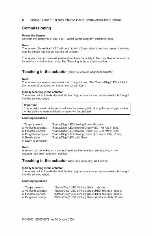
Commissioning
Power the SensorConnect the sensor to 24Vdc. See "Typical Wiring Diagram" section for help.
Note:The sensor "Status/Diag" LED will begin to blink Green eight times then repeat, indicatingthat the sensor has not yet learned an actuator.
The sensor can be commissioned to either have the ability to learn another actuator or belocked for a one time learn only. See ‘Teaching in the actuator’ section.
Teaching in the actuator (Ability to learn an additional actuator)
Note:The sensor can learn a new actuator up to eight times. The "Status/Diag" LED will blinkthe number of actuators left that an sensor can learn.
Initially teaching in the actuatorThe sensor will automatically start the learning process as soon as an actuator is broughtinto the sensing range.
Important!The actuator must not be removed from the sensing field during the learning procedureor the ability to learn additional actuator will be disabled.
Learning Sequence
1.Target present: "Status/Diag" LED blinking Green 1Hz rate2. Verifying actuator: "Status/Diag" LED blinking Green/RED 1Hz rate (15sec)3. Program Sensor: "Status/Diag" LED blinking Green/RED 4Hz rate (15sec)4. Program Complete: "Status/Diag" LED blinking Green (# of learns left) (15 sec)5. Ready state: "Status/Diag" LED solid Green6. Learn is complete
Note:A sensor can be locked so it can not learn another actuator; see teaching in the actuator (one time learn only) section.
Teaching in the actuator (One time learn only; Unit locked)
Initially teaching in the actuatorThe sensor will automatically start the learning process as soon as an actuator is broughtinto the sensing range.
Learning Sequence
1. Target present: "Status/Diag" LED blinking Green 1Hz rate2. Verifying actuator: "Status/Diag" LED blinking Green/RED 1Hz rate (15sec)3. Program Sensor: "Status/Diag" LED blinking Green/RED 4Hz rate (15sec)4. Program Locking: "Status/Diag" LED blinking Green (# of learn left) (15 sec)

PN-46045 10000054879 Ver 00 October 2009
SensaGuardTM 18 mm Plastic Barrel Installation Instructions 7
During the Program Locking Stage, perform the following steps:a. Remove the actuator from the sensing field, until the "Status/Diag" LED changes to
solid Red.b. Replace the actuator back into the sensing field and the "Status/Diag" LED will
continue blinking Green (# of learns left).
Note: The program locking sequence must be completed within the 15 secondprogram locking window.
5. Ready state: "Status/Diag" LED solid Green
6. Learn is complete
Learning a new actuator:
To learn a replacement actuator; bring the actuator to be taught into the sensing range ofthe safety switch.
The learn sequence is same as the sequence for commissioning the first actuator.
Note: A sensor can be locked so it can not learn another actuator by removing the actuatorfrom the sensing field during the 15 sec "Program Complete" sequence.
A sensor can not re-learn a previously learned actuator or a standard SensaGuard actuator.
Unique Coded Diagnostic:Error codes for learning process - Repeat until unit is power cycled
Status/Diag LED - Flashes (4Hz) Error Code
Green OSSD inputs not valid
Red-Red-Red-Green Can not learn a standard SensaGuard Actuator
Red-Red-Red-Green-Green Actuator already learned
Red-Red-Red-Green-Green-Green Bad RFID; Target moved out of range
Red-Red-Red-Green-Green-Green-Green Exceeded learning 8 actuators
Red-Red-Red-Green-Green-Green-Green-Green Unit locked: Can not learn another actuator

PN-46045 10000054879 Ver 00 October 2009
8 SensaGuardTM 18 mm Plastic Barrel Installation Instructions
TroubleshootingSeries Circuit
Yel
Red
Brown
Gray
Pink
Blu
e
24V
DC
Pow
erS
upp
ly
1606
-XL1
20D
Sw
itch
1
+24
RTN
Sw
itch
2
White
Whit
eYel
Red
Brown
Gray
Pink
Blu
e
Act
uato
r 1
Act
uato
r 2
Sw
itch
3
Whit
eYel
Red
Brown
Gray
Pink
Blu
e
Act
uato
r 3
Sw
itch
4
Whit
eYel
Red
Brown
Gray
Pink
Blu
e
Act
uato
r 4
Sw
itch
5
Whit
eYel
Red
Brown
Gray
Pink
Blu
e
Act
uato
r 5
+24
V+
24 V
+24
V+
24 V
+0
V+
0 V
+0
V+
0 V
+0
V+
0 V
Act
uato
r 2
is in
sen
sing
ran
ge.
Sw
itch
2 is
func
tioni
ng p
rop
erly
OS
SD
s ar
e en
ergi
ze t
o 24
VG
reen
LE
D is
ON
.
Act
uato
r 3
is in
sen
sing
ran
ge.
Sw
itch
3 ha
s fa
ult.
See
Tab
le A
bov
e—R
ed L
ED
is fl
ashi
ng
Act
uato
r 1
is in
sen
sing
ran
ge.
Sw
itch
1 is
func
tioni
ng p
rop
erly
OS
SD
s ar
e en
ergi
ze t
o 24
VG
reen
LE
D is
ON
.
Act
uato
r 4
is in
sen
sing
ran
ge.
Sw
itch
4 is
func
tioni
ng p
rop
erly
.S
erie
s in
put
s ar
e 0
V.
OS
SD
s ar
e d
e-en
ergi
zed
to
0V.
Gre
en L
ED
is F
lash
ing
to in
dic
ate
Ser
ies
inp
uts
are
not
24V.
Act
uato
r 5
is in
sen
sing
ran
ge.
Sw
itch
5 is
func
tioni
ng p
rop
erly
.S
erie
s in
put
s ar
e 0
V.
OS
SD
s ar
e d
e-en
ergi
zed
to
0V
.G
reen
LE
D is
Fla
shin
g to
ind
icat
eS
erie
s in
put
s ar
e no
t 24
V.
OS
SD
’s a
re O
FFR
ecov
erab
le fa
ult
Note: Refer to Technical Specifications for Certification information and ratings.

PN-46045 10000054879 Ver 00 October 2009
SensaGuardTM 18 mm Plastic Barrel Installation Instructions 9
Unit Response Time (does not include safety relay response time)
Yel
Red
Whi
teG
ray
Pink
Blue
24V
DCPo
wer
Supp
ly
1606
Sensor 1
+24
RT
Sensor 2
Brow
n
Brown
Gra
yPi
nkW
hite
Yel
Red
Blue
Sensor 3
Brown
Yel
Red
Whi
teG
ray
Pink
Blue
A1 S21
S11
4133
2313
S12
S52
4234
2414
A2S3
4S2
2
440R
-N23
126
Actuator 1
Actuator 2
Actuator 3
Initi
al C
ondi
tions
:Al
l act
uato
rs a
re in
sen
sing
dist
ance
.
Actu
ator
1 is
mov
ed o
ut o
fse
nsin
g ra
nge.
Sens
or 2
dro
ps th
e 24
vol
ts
(red
and
yello
w) f
rom
Sen
sor 1
O
SSD
outp
uts.
Gre
en L
ED fl
ashe
s.
Sens
or 3
dro
ps th
e 24
vol
ts
(red
and
yello
w) f
rom
Sen
sor 2
O
SSD
outp
uts.
Gre
en L
ED fl
ashe
s.
0 m
S54
mS
72 m
S90
mS
Actu
ator
1 is
out
of s
ensin
g ra
nge.
Actu
ator
2 a
nd 3
are
in
sens
ing
rang
e.
Actu
ator
1 is
mov
ed in
to s
ensin
g ra
nge.
Sens
or 1
OSS
D ou
tput
s ar
e en
ergi
zed.
Sens
or 2
OSS
D in
puts
(red
and
yel
low
) tra
nsiti
on to
24V
DC
from
Sen
sor 1
O
SSD
outp
uts.
Sens
or 2
OSS
D ou
tput
s ar
e en
ergi
zed
Sens
or 3
OSS
D in
puts
(red
and
ye
llow
) tra
nsiti
on to
24V
DC
from
Se
nsor
2 O
SSD
outp
uts.
Sens
or 3
OSS
D ou
tput
s ar
e en
ergi
zed.
0 m
S36
0 m
S37
8 m
S39
6 m
S
OFF ON
Note: Refer to Technical Specifications for Certification information and ratings.
PN-46045 10000054879 Ver 00 October 2009
10 SensaGuardTM 18 mm Plastic Barrel Installation Instructions
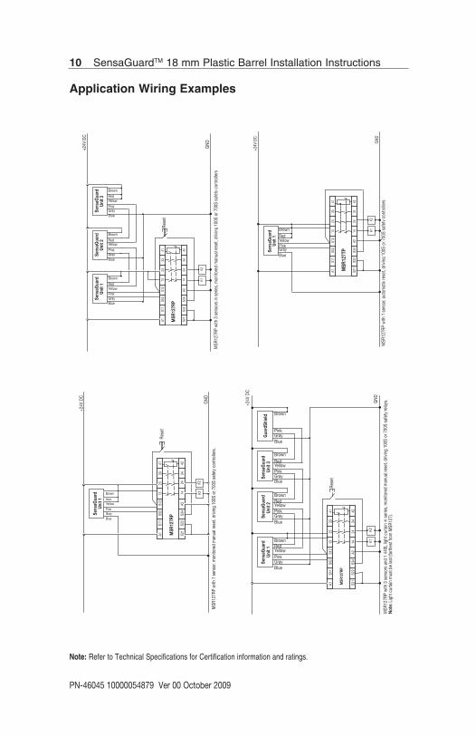
Application Wiring Examples
K1
+24V
DC
MSR
127R
P w
ith 1
sen
sor,
mon
itore
d m
anua
l res
et, d
rivin
g 10
0S o
r 700
S sa
fety
con
trolle
rs.
A1S1
1S5
2S1
213
2333
41
S21
S22
S34
A214
2434
42
MSR
127R
P
Rese
t
GND
BlueGrayPink
YellowRed
Brown
Sens
aGua
rdUn
it 1
K2
+24V
DC
GND
MSR
127R
P w
ith 3
sen
sors
in s
erie
s, m
onito
red
man
ual r
eset
, driv
ing
100S
or 7
00S
safe
ty c
ontro
llers
BlueGrayPinkYellowRed
Brown
Sens
aGua
rdUn
it 1
Sens
aGua
rdUn
it 2
Sens
aGua
rdUn
it 3
K1
A1S1
1S5
2S1
213
2333
41
S21
S22
S34
A214
2434
42
MSR
127R
P
Rese
t
K2
BlueGrayPinkYellowRed
Brown
BlueGrayPink
YellowRedBrown
MSR
127R
P w
ith 3
sen
sors
and
1 4
40L
light
cur
tain
in s
erie
s, m
onito
red
man
ual r
eset
, driv
ing
100S
or 7
00S
safe
ty re
lays
.No
te: L
ight
cur
tain
mus
t be
last
(far
thes
t fro
m M
SR12
7).
GND
A1S1
1S5
2S1
213
2333
41
S21
S22
S34
A214
2434
42
MSR
127R
P
Rese
t
K1K2
+24V
DC
BlueGrayPinkYellowRedBrown
Sens
aGua
rdUn
it 1
Sens
aGua
rdUn
it 2
Sens
aGua
rdUn
it 3
Gua
rdSh
ield
BlueGrayPinkYellowRedBrown
BlueGrayPinkYellowRedBrown
BlueGrayPink
Brown
A1S1
1S5
2S1
213
2333
41
S21
S22
S34
A214
2434
42
MSR
127T
P
GND
MSR
127R
P w
ith 1
sen
sor,
auto
mat
ic re
set,
drivi
ng 1
00S
or 7
00S
safe
ty c
ontro
llers
+24V
DC
Sens
aGua
rdUn
it 1
K1K2
BlueGrayPinkYellowRedBrown
Note: Refer to Technical Specifications for Certification information and ratings.

PN-46045 10000054879 Ver 00 October 2009
SensaGuardTM 18 mm Plastic Barrel Installation Instructions 11
Application Wiring Examples
MSR
127T
P w
ith 3
sen
sors
in s
erie
s, a
utom
atic
rese
t, dr
iving
100
S or
700
S re
lays
.
MSR
127T
P
+24V
DC
GND
Blue
GrayPink
YellowRed
Brown
Sens
aGua
rdUn
it 1
K1
A1S1
1S5
2S1
213
2333
41
S21
S22
S34
A214
2434
42
K2
Blue
GrayPink
YellowRed
Brown
Blue
GrayPink
YellowRed
Brown
Sens
aGua
rdUn
it 3
Sens
aGua
rdUn
it 2
MSR
127T
P w
ith 3
sen
sors
and
1 4
40L
light
cur
tain
in s
erie
s, a
utom
atic
rese
t, dr
iving
100
S or
700
S sa
fety
con
tact
ors.
Note
: Lig
ht c
urta
in m
ust b
e la
st (f
arth
est f
rom
MSR
127)
MSR
127T
P
GND
A1S1
1S5
2S1
213
2333
41
S21
S22
S34
A214
2434
42
K1K2
+24V
DC
Blue
GrayPink
YellowRed
Brown
Blue
GrayPink
YellowRed
Brown
Blue
GrayPink
YellowRed
Brown
Blue
GrayPink
Brown
Gua
rdSh
ield
Sens
aGua
rdUn
it 1
Sens
aGua
rdUn
it 3
Sens
aGua
rdUn
it 2
Note: Refer to Technical Specifications for Certification information and ratings.

12 SensaGuardTM 18 mm Plastic Barrel Installation Instructions
Application Wiring Examples
MSR
200
serie
s w
ith 3
sen
sors
and
1 4
40L
light
cur
tain
, aut
omat
ic re
set,
drivi
ng 1
00S
or 7
00S
safe
ty c
onta
ctor
s.No
te: L
i ght
cur
tain
can
be
atta
ched
to a
ny in
put
Gua
rdSh
ield
+24V
DC
GND
440R
-H23
177
Y40
Y41
S51
S12
S20
S32
S11
S21
S31
S41
1323
31Y4
2A1
S32
S20
S12
S42
S50
S62
S34
Y1Y2
Y314
2432
Y32
Y33
Y30
A2S6
2S5
0S4
2440R
-H23
179
K1
S32
S20
S12
S62
S50
S42
S32
S32
440R
-H23
180
MSR
221P
MSR
211P
MSR
230P
K2K1 K2
K3
K4
Sens
aGua
rd
Blue
Brown
Gra
yPi
nk
Blue
Brown
Yellow
Red
Gra
yPi
nk
Sens
aGua
rdSe
nsaG
uard
Gra
yPi
nkG
ray
Pink
Blue
Brown
Yellow
Red
Blue
Brown
Yellow
RedM
SR20
0 se
ries
with
3 s
enso
rs a
nd 1
440
L lig
ht c
urta
in, m
anua
l res
et, d
rivin
g 10
0S o
r 700
S sa
fety
con
tact
ors.
Note
: Lig
ht c
urta
in c
an b
e at
tach
ed to
any
inpu
t.
Rese
t
Gua
rdSh
ield
+24V
DC
GND
440R
-H23
177
Y40
Y41
S51
S12
S20
S32
S11
S21
S31
S41
1323
31Y4
2A1
S32
S20
S12
S42
S50
S62
S34
Y1Y2
Y314
2432
Y32
Y33
Y30
A2S6
2S5
0S4
2440R
-H23
179
K1
S32
S20
S12
S62
S50
S42
S32
S32
440R
-H23
180
MSR
221P
MSR
211P
MSR
230P
K2K1 K2
K3
K4
Sens
aGua
rd
Blue
Brown
Gra
yPi
nk
Blue
Brown
Yellow
Red
Gra
yPi
nk
Sens
aGua
rdSe
nsaG
uard
Gra
yPi
nkG
ray
Pink
Blue
Brown
Yellow
Red
Blue
Brown
Yellow
Red
Note: Refer to Technical Specifications for Certification information and ratings.
PN-46045 10000054879 Ver 00 October 2009

PN-46045 10000054879 Ver 00 October 2009
SensaGuardTM 18 mm Plastic Barrel Installation Instructions 13
Application Wiring Examples
MSR
200
serie
s w
ith 4
sen
sors
, aut
omat
ic re
set,
drivi
ng 1
00S
or 7
00S
safe
ty c
onta
ctor
s.
Yellow
Red
+24V
DC
GND
440R
-H23
177
Y40
Y41
S51
S12
S20
S32
S11
S21
S31
S41
1323
31Y4
2A1
S32
S20
S12
S42
S50
S62
S34
Y1Y2
Y314
2432
Y32
Y33
Y30
A2S6
2S5
0S4
2440R
-H23
179
K1
S32
S20
S12
S62
S50
S42
S32
S32
440R
-H23
180
MSR
221P
MSR
211P
MSR
230P
K2K1 K2
K3
K4
Sens
aGua
rdSe
nsaG
uard
Blue
Brown
Gra
yPi
nk
Blue
Brown
Yellow
Red
Gra
yPi
nk
Sens
aGua
rdSe
nsaG
uard
Gra
yPi
nkG
ray
Pink
Blue
Brown
Yellow
Red
Blue
Brown
Yellow
Red
MSR
200
serie
s w
ith 4
sen
sors
, man
ual r
eset
, driv
ing
100S
or 7
00S
safe
ty c
onta
ctor
s.
Rese
t
+24V
DC
GND
440R
-H23
177
Y40
Y41
S51
S12
S20
S32
S11
S21
S31
S41
1323
31Y4
2A1
S32
S20
S12
S42
S50
S62
S34
Y1Y2
Y314
2432
Y32
Y33
Y30
A2S6
2S5
0S4
2440R
-H23
179
K1
S32
S20
S12
S62
S50
S42
S32
S32
440R
-H23
180
MSR
221P
MSR
211P
MSR
230P
K2K1 K2
K3
K4
Sens
aGua
rdSe
nsaG
uard
Blue
Brown
Gra
yPi
nk
Blue
Brown
Yellow
Red
Yellow
Red
Gra
yPi
nk
Sens
aGua
rdSe
nsaG
uard
Gra
yPi
nkG
ray
Pink
Blue
Brown
Yellow
Red
Blue
Brown
Yellow
Red
Note: Refer to Technical Specifications for Certification information and ratings.

14 SensaGuardTM 18 mm Plastic Barrel Installation Instructions
List of recommended relays
MSR126, MSR127, MSR123, MSR124, MSR131, MSR138, MSR211, MSR121, MSR320, MSR200Family (Except MSR210), MSR300 Family, SmartGuard, 1791 DS DeviceNet™ Safety I/O.
Relay must have light curtain inputs.
MaintenanceEvery week.Check the correct operation of the switching circuit. Also check for signs of abuse or tampering.Inspect the switch casing for damage
RepairIf there is any malfunction or damage, no attempts at repair should be made. The unit should bereplaced before machine operation is allowed.
Declaration of ConformityThis is to declare that the products shown on this document conforms with the Essential Health andSafety Requirements (EHSR’s) of the European Machinery Directive (73/23/EEC as amended by93/68/EEC). These products also conform to EN 60947-5-3, EN 1088, EN292, EN 60204-1 and haveThird Party Approval.
For a comprehensive certificate please visit: www.ab.com/safety.
PN-46045 10000054879 Ver 00 October 2009
Check the machine is isolated and stopped whenever the interlocked guard door is open.
IMPORTANT: Afterinstallation and commissioning, the actuator, switch and switch lid fixing screws should be coated with tamper evident varnish or similar compound.
R
Copyright © 2012 Rockwell Automation, Inc. All Rights Reserved.