senior design team 05910 rmsc robotics display mentor: bill scarbrough team leader: amy tatro (me)...
Post on 20-Dec-2015
217 views
TRANSCRIPT
Senior Design TeamSenior Design Team0591005910
RMSC Robotics DisplayRMSC Robotics Display
Senior Design TeamSenior Design Team0591005910
RMSC Robotics DisplayRMSC Robotics Display
Mentor: Bill ScarbroughMentor: Bill ScarbroughTeam Leader: Amy Tatro (ME)Team Leader: Amy Tatro (ME)
Mary Beth Belczak (ME)Mary Beth Belczak (ME)Matt Boecke (EE)Matt Boecke (EE)John Byrne (ME)John Byrne (ME)Mike Rhault (ME)Mike Rhault (ME)

Project Overview• Project Background
– The Rochester Museum and Science Center has demonstrated an interest in changing their image.
– Recent developments have changed the museum from a place of observation to an interactive learning center.
– The Rochester Museum and Science Center would like to increase the amount of hands-on exhibits at the center.
Project Overview• Project Background (cont’d)
− The mission of this project is to create an interactive robotics display for the Rochester Museum and Science Center.
− RMSC stressed that the project must meet eight basic requirements.

Project Overview• Needs Assessment
−The display must be geared towards children ages 8-14.
−The exhibit must carry a high attractor factor.
−The display must allow the patron to interact with the exhibit.
−People who are not using the exhibit must be able to watch and be entertained.

Project Overview• Needs Assessment (cont’d)
– Prototyping will be a necessary step to eliminate the “Human Factor”.
– The experience at the exhibit does not have to be entirely educational.
– The exhibit should be easy to use without much instruction.
– A service manual should be provided for maintenance.
Design Process• Concept Development
– Two phase concept development.– Eight initial proposals were delivered to
RMSC for review.– After proposal was chosen, more detailed
design ideas were discussed.

Design Process• Final Design
– A small robotic arm assembles a gear train for a clock.
– A manually operated arm is available for patron use.
– The user can assemble gears with the arm through the use of a control panel.
– The user can race the clock by attempting to build a gear train of their own in the allotted time.

Design Process• Project Schedule
– Senior Design I• Week 1: Project Selection• Week 2: Project Assignment• Week 3: Brainstorming• Week 4: Needs Assessment• Week 5: Preliminary Concept Development• Week 6: Preliminary Design for Air Hockey Robot• Week 7: Final Project Selected, Brainstorming• Week 8: Final Concept Development• Week 9: Preliminary Design, Feasibility• Week 10: Final Proposal Modification, PDR Preparation

Design Process• Project Schedule
– Winter Quarter• Design Development• Selection of Major Components• Robotic arm Acquisition• Preliminary Programming
– Senior Design II• Week 1: Final Design, Selection of Most Components• Week 2: BOM finalization, component purchasing• Week 3: Fabrication and Programming• Week 4: Fabrication and Programming• Week 5: Fabrication and Programming• Week 6: Assembly, Fabrication, and Programming• Week 7: Assembly, Fabrication, and Programming• Week 8: Assembly, Fabrication, Programming, Conference Paper,
Poster, and Website• Week 9: Assembly, Fabrication, Programming, Website, and CDR
Preparation• Week 10: Assembly, Fabrication, Programming, Website, and CDR
Preparation

Major Design Challenges
• Components were tailored made to enhance the visual appeal of the exhibit, resulting in an extensive fabrication phase.
• Electrical and Programming demands exceeded the capacity of the team.
• Finding robust, inexpensive robotic arms.• Programming exhibit modules to
communicate to each other.• Designing a robust exhibit that can withstand
many uses without repair.

Final Design• Overview
– User selects difficulty level.– Automated robotic arm places gears in path.– Clock starts timing users.– Users manually control robotic arm to assemble
gears.– When time is up, gears are reset on automated and
user’s sides.

Final Design• Automated side
– Robot– Rail System– Gear Train and Clock
• User’s Side– Robot– Sweeper System– Gears– Motorized Peg System
• Controls– Touch-Screen– Microcontroller– Control Panel

Final Design• Automated Side
– Robot• High quality non-industrial robot• Max Specs: 12” Reach, 0.89lb Payload• End-Effector: Electromagnet with 28 lbs of lift• Driven by microcontroller• Reach extended by Rail System

Final Design• Automated Side
– Rail System• Gives automated robot larger reach envelope• Driven by rack and pinion components• Stepper motor used for precise movement along
rails

Final Design• Automated Side
– Rail System• Displacement Analysis
Final Design• Automated Side
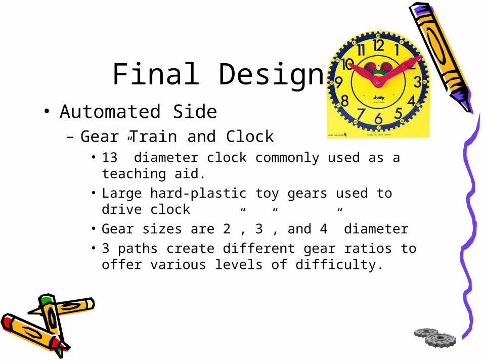
– Gear Train and Clock• 13” diameter clock commonly used as a teaching
aid.• Large hard-plastic toy gears used to drive clock• Gear sizes are 2”, 3”, and 4” diameter• 3 paths create different gear ratios to offer
various levels of difficulty.

Final Design• Automated Side
– Gear Train and Clock
Beginner Intermediate Advanced

Final Design• User’s Side
– Robot• Physical specifications of the robot are the same
as automatic side.• Controlled by the control panel interface.• Base is fixed resulting in no lateral movement, for
simplicity.
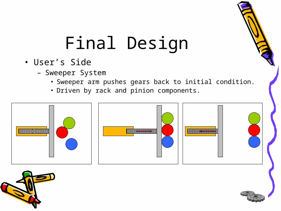
Final Design• User’s Side
– Sweeper System• Sweeper arm pushes gears back to initial condition.• Driven by rack and pinion components.

Final Design• User’s Side
– Gears• One size gear is used so that they can be placed
on any peg.• Gears are within reach of robot and robot does
not reach beyond the sweeper arm.• Sensors under each gear determine when a user
successfully completes the task.• When task is completed, DC motor driven gear
spins gears.

Final Design• User’s Side
– Motorized Peg System• Lowers pegs and drive gear below the surface of
the Plexiglas®.• Stepper motor drives cams to compress spring
loaded system.
Final Design• Controls
– Touch-Screen• 433 MHz embedded Celeron® Processor• 256 MB PC100 RAM• 20 Gig Fujitsu Hard drive• 3 Serial COM ports• 800x600 Screen resolution• 2 PC card slot expansions
Final Design• Controls
– Microcontroller• 8051 based architecture• 100 MHz processing speed• 6 PWM lines• 2 UARTS• 8k RAM• 64 I/O lines• Supports C language

Final Design• Controls
– Control Panel• 9 Buttons• 8 control the direction of servos on the robot.• 1 button dedicated to electromagnet control.
Shoulder
Elbow Wrist Base
Magnet

Conclusion• Exhibit draws patrons with bright colors, motion, and
mechanical sounds.• Components are heavy duty to withstand continued use.• Exaggerated components appeal to people of all ages. • Patrons nearby the exhibit are entertained along with
the user.• Exhibit is safe for user’s since it will be encased with
Plexiglas.• Testing phase was not completed due to time
constraints.

Acknowledgements• Dave, Steve, and Rob for their help in
the machine shop.• Professor Scarbrough for his guidance.• Marc Check, Rich Smith, and RMSC for
all their insight and assistance.• Jason Kelly and Eric Schreiber for their
support on this project without receiving school credit.

Questions?