semi e5-0301 semi equipment communications …zb.guaihou.com/stdpool/semi e5-0301 semi equipment...
TRANSCRIPT

SEMI E5-0301 © SEMI 1982, 20011
SEMI E5-0301SEMI EQUIPMENT COMMUNICATIONS STANDARD 2 MESSAGECONTENT (SECS-II)
This standard was technically approved by the Global Information & Control Committee and is the directresponsibility of the North American Information & Control Committee. Current changes approved by theJapanese Regional Standards Committee on December 1, 2000. Initially available at www.semi.org January2001; to be published March 2001. Originally published in 1982; previously published October 2000.
NOTICE: The user’s attention is called to thepossibility that some implementations of this standard,particularly those related to the use of Stream 4, mayinvolve the use of inventions covered by U.S. patents4,884,674 and 5,216,613, and by other patents issued orpending, held by Texas Instruments Incorporated. Bypublication of this standard, SEMI takes no positionrespecting either the applicability or the validity ofthese or other patent rights asserted in connection withany item mentioned in this standard. Users of thisstandard are expressly advised that determination ofany such patent rights, and the risk of infringement ofsuch rights, are entirely their own responsibility.
CONTENTS
1 Introduction1.1 Intent1.2 Overview1.3 Application1.4 Applicable Documents
2 Selected Definitions
3 The Message Transfer Protocol3.1 Intent3.2 Messages3.2 Blocking Requirements3.2 Message Header3.2 The Transaction Timeout3.2 Multiple Open Transaction
4 Streams and Functions4.1 Streams4.2 Functions4.3 Stream and Function Allocation
5 Transaction and Conversation Protocols5.1 Intent5.2 Transaction Definition5.3 Transaction Level Requirements5.4 Conversation Protocols
6 Data Structures6.1 Intent6.2 Item
6.3 List6.4 Localized Character String Items6.5 Example Data Structures6.6 Data Item Dictionary6.7 Variable Item Dictionary6.8 Object Dictionary
7 Message Detail7.1 Intent7.4 Stream 0 and Function 07.5 Stream 1 Equipment Status
S1,F0 Abort Transaction (S1F0)S1,F1 Are You There Request (R)S1,F2 On Line Data (D)S1,F3 Selected Equipment Status Request
(SSR)S1,F4 Selected Equipment Status Data (SSD)S1,F5 Formatted Status Request (FSR)S1,F6 Formatted Status Data (FSD)S1,F7 Fixed Form Request (FFR)S1,F8 Fixed Form Data (FFD)S1,F9 Material Transfer Status Request (TSR)S1,F10 Material Transfer Status Data (TSD)S1,F11 Status Variable NameList Request
(SVNR)S1,F12 Status Variable NameList Reply
(SVNRR)S1,F13 Establish Communications Request (CR)S1,F14 Establish Communications Request
Acknowledge (CRA)S1,F15 Request OFF-LINE (ROFL)S1,F16 OFF-LINE Acknowledge (OFLA)S1,F17 Request ON-LINE (RONL)S1,F18 ON-LINE Acknowledge (ONLA)
Macro Level MessagesS1,F19 Get Attribute (GA)S1,F20 Attribute Data (AD)
7.6 Stream 2 Equipment Control and DiagnosticsS2,F0 Abort Transaction (S2F0)S2,F1 Service Program Load Inquire (SPI)S2,F2 Service Program Load Grant (SPG)S2,F3 Service Program Send (SPS)S2,F4 Service Program Send Acknowledge
(SPA)S2,F5 Service Program Load Request (SPR)

SEMI E5-0301 © SEMI 1982, 2001 2
S2,F6 Service Program Load Data (SPD)S2,F7 Service Program Run Send (CSS)S2,F8 Service Program Run Acknowledge
(CSA)S2,F9 Service Program Results Request (SRR)S2,F10 Service Program Results Data (SRD)S2,F11 Service Program Directory Request
(SDR)S2,F12 Service Program Directory Data (SDD)S2,F13 Equipment Constant Request (ECR)S2,F14 Equipment Constant Data (ECD)S2,F15 New Equipment Constant Send (ECS)S2,F16 New Equipment Constant Acknowledge
(ECA)S2,F17 Date and Time Request (DTR)S2,F18 Date and Time Data (DTD)S2,F19 Reset/Initialize Send (RIS)S2,F20 Reset Acknowledge (RIA)S2,F21 Remote Command Send (RCS)S2,F22 Remote Command Acknowledge (RCA)S2,F23 Trace Initialize Send (TIS)S2,F24 Trace Initialize Acknowledge (TIA)S2,F25 Loopback Diagnostic Request (LDR)S2,F26 Loopback Diagnostic Data (LDD)S2,F27 Initiate Processing Request (IPR)S2,F28 Initiate Processing Acknowledge (IPA)S2,F29 Equipment Constant Namelist Request
(ECNR)S2,F30 Equipment Constant Namelist (ECN)S2,F31 Date and Time Set Request (DTS)S2,F32 Date and Time Set Acknowledge (DTA)S2,F33 Define Report (DR)S2,F34 Define Report Acknowledge (DRA)S2,F35 Link Event Report (LER)S2,F36 Link Event Report Acknowledge
(LERA)S2,F37 Enable/Disable Event Report (EDER)S2,F38 Enable/Disable Event Report
Acknowledge (EERA)S2,F39 Multi-block Inquire (DMBI)S2,F40 Multi-block Grant (DMBG)S2,F41 Host Command Send (HCS)S2,F42 Host Command Acknowledge (HCA)S2,F43 Reset Spooling Streams and Functions
(RSSF)S2,F44 Reset Spooling Acknowledge (RSA)S2,F45 Define Variable Limit Attributes
(DVLA)S2,F46 Variable Limit Attribute Acknowledge
(VLAA)S2,F47 Variable Limit Attribute Request
(VLAR)S2,F48 Variable Limit Attribute Send (VLAS)S2,F49 Enhanced Remote CommandS2,F50 Enhanced Remote Command
Acknowledge
7.7 Stream 3 Material StatusS3,F0 Abort Transaction (S3F0)S3,F1 Material Status Request (MSR)S3,F2 Material Status Data (MSD)S3,F3 Time to Completion Request (TCR)S3,F4 Time to Completion Data (TCD)S3,F5 Material Found Send (MFS)S3,F6 Material Found Acknowledge (MFA)S3,F7 Material Lost Send (MLS)S3,F8 Material Lost Acknowledge (MLA)S3,F9 Material ID Equate Send (IES)S3,F10 Material ID Equate Acknowledge (IEA)S3,F11 Material ID Request (MIDR)S3,F12 Material ID Request Acknowledge
(MIRA)S3,F13 Material ID Send (MIS)S3,F14 Material ID Acknowledge (MIA)S3,F15 Materials Multi-Block Inquire (MMBI)S3,F16 Materials Multi-Block Grant (MMBG)S3,F17 Carrier Action RequestS3,F18 Carrier Action AcknowledgeS3,F19 Cancel All Carrier Out RequestS3,F20 Cancel All Carrier Out AcknowledgeS3,F21 Port Group DefinitionS3,F22 Port Group Definition AcknowledgeS3,F23 Port Group Action RequestS3,F24 Port Group Action AcknowledgeS3,F25 Port Action RequestS3,F26 Port Action Acknowledge
7.8 Stream 4 Material ControlS4,F0 Abort Transaction (S4F0)S4,F1 Ready to Send Material (RSN)S4,F2 Ready to Send Acknowledge (RSA)S4,F3 Send Material (SMN)S4,F4 Not UsedS4,F5 Handshake Complete (HCN)S4,F6 Not UsedS4,F7 Not Ready to Send (ABN)S4,F8 Not UsedS4,F9 Stuck in Sender (SSN)S4,F10 Not UsedS4,F11 Stuck in Receiver (SRN)S4,F12 Not UsedS4,F13 Send Incomplete Timeout (SIN)S4,F14 Not UsedS4,F15 Material Received (MRN)S4,F16 Not UsedS4,F17 Request to Receive (RTR)S4,F18 Request to Receive Acknowledge (RRA)
Macro Level MessagesS4,F19 Transfer Job Create (TJ)S4,F20 Transfer Job Acknowledge (TJA)S4,F21 Transfer Job Command (TJC)S4,F22 Transfer Command Acknowledge (TCA)S4,F23 Transfer Job Alert (TJA)

SEMI E5-0301 © SEMI 1982, 20013
S4,F24 Transfer Alert Acknowledge (TLA)S4,F25 Multi-Block Inquire (MBI4)S4,F26 Multi-Block Grant (MBG4)
Micro Level MessagesS4,F27 Handoff Ready (HR)S4,F28 Not UsedS4,F29 Handoff Command (HC)S4,F30 Not UsedS4,F31 Handoff Command Complete (HCC)S4,F32 Not UsedS4,F33 Handoff Verify (HV)S4,F34 Not UsedS4,F35 Handoff Cancel Ready (HCR)S4,F36 Not UsedS4,F37 Handoff Cancel Ready Acknowledge
(HCA)S4,F38 Not UsedS4,F39 Handoff Halt (HH)S4,F40 Not UsedS4,F41 Handoff Halt Acknowledge (HHA)S4,F42 Not Used
7.9 Stream 5 Exception HandlingS5,F0 Abort Transaction (S5F0)S5,F1 Alarm Report Send (ARS)S5,F2 Alarm Report Acknowledge (ARA)S5,F3 Enable/Disable Alarm Send (EAS)S5,F4 Enable/Disable Alarm Acknowledge
(EAA)S5,F5 List Alarms Request (LAR)S5,F6 List Alarm Data (LAD)S5,F7 List Enabled Alarm Request (LEAR)S5,F8 List Enabled Alarm Data (LEAD)S5,F9 Exception Post Notify (EXPN)S5,F10 Exception Post Confirm (EXPC)S5,F11 Exception Clear Notify (EXCN)S5,F12 Exception Clear Confirm (EXCC)S5,F13 Exception Recover Request (EXRR)S5,F14 Exception Recover Acknowledge
(EXRA)S5,F15 Exception Recovery Complete Notify
(EXRCN)S5,F16 Exception Recovery Complete Confirm
(EXRCC)S5,F17 Exception Recovery Abort Request
(EXRAR)S5,F18 Exception Recovery Abort Acknowledge
(EXRAA)
7.10 Stream 6 Data CollectionS6,F0 Abort Transaction (S6F0)S6,F1 Trace Data Send (TDS)S6,F2 Trace Data Acknowledge (TDA)S6,F3 Discrete Variable Data Send (DVS)S6,F4 Discrete Variable Data Acknowledge
(DVA)
S6,F5 Multi-block Data Send Inquire (MBI)S6,F6 Multi-block Grant (MBG)S6,F7 Data Transfer Request (DDR)S6,F8 Data Transfer Data (DDD)S6,F9 Formatted Variable Send (FVS)S6,F10 Formatted Variable Acknowledge (FVA)S6,F11 Event Report Send (ERS)S6,F12 Event Report Acknowledge (ERA)S6,F13 Annotated Event Report Send (AERS)S6,F14 Annotated Event Report Acknowledge
(AERA)S6,F15 Event Report Request (ERR)S6,F16 Event Report Data (ERD)S6,F17 Annotated Event Report Request
(AERR)S6,F18 Annotated Event Report Data (AERD)S6,F19 Individual Report Request (IRR)S6,F20 Individual Report Data (IRD)S6,F21 Annotated Individual Report (AIR)S6,F22 Annotated Individual Report Data
(AIRD)S6,F23 Request Spooled Data (RSD)S6,F24 Request Spooled Data
Acknowledgement Send (RSDAS)S6,F25 Notification Report SendS6,F26 Notification Report Send AcknowledgeS6,F27 Trace Report Send (TRS)S6,F28 Trace Report Send Acknowledge
(TRSA)
S6,F29 Trace Report Request (TRR)S6,F30 Trace Report Data (TRD)
7.11 Stream 7 Process Program ManagementS7,F0 Abort Transaction (S7F0)S7,F1 Process Program Load Inquire (PPI)S7,F2 Process Program Load Grant (PPG)S7,F3 Process Program Send (PPS)S7,F4 Process Program Acknowledge (PPA)S7,F5 Process Program Request (PPR)S7,F6 Process Program Data (PPD)S7,F7 Process Program ID Request (PIR)S7,F8 Process Program ID Data (PID)S7,F9 M/P M Request (MMR)S7,F10 M/P M Data (MMD)S7,F11 M/P M Update Send (UMS)S7,F12 M/P M Update Acknowledge (UMA)S7,F13 Delete M/P M Entry Send (DES)S7,F14 Delete M/P M Entry Acknowledge
(DEA)S7,F15 Matrix Mode Select Send (MMS)S7,F16 Matrix Mode Select Acknowledge
(MMA)S7,F17 Delete Process Program Send (DPS)S7,F18 Delete Process Program Acknowledge
(DPA)S7,F19 Current EPPD Request (RER)

SEMI E5-0301 © SEMI 1982, 2001 4
S7,F20 Current EPPD Data (RED)S7,F21 Equipment Process Capabilities Request
(PCR)S7,F22 Equipment Process Capabilities Data
(PCD)S7,F23 Formatted Process Program Send (FPS)S7,F24 Formatted Process Program
Acknowledge (FPA)S7,F25 Formatted Process Program Request
(FPR)S7,F26 Formatted Process Program Data (FPD)S7,F27 Process Program Verification Send
(PVS)S7,F28 Process Program Verification
Acknowledge (PVA)S7,F29 Process program Verification Inquire
(PVI)S7,F30 Process Program Verification Grant
(PVG)S7,F31 Verification Request Send (VRS)S7,F32 Verification Request Acknowledge
(VRA)S7,F33 Process Program Available Request
(PAR)S7,F34 Process Program Availability Data
(PAD)S7,F35 Process Program for MID Request
(PPMR)S7,F36 Process Program for MID Data (PPMD)
7.12 Stream 8 Control Program TransferS8,F0 Abort Transaction (S8F0)S8,F1 Boot Program Request (BPR)S8,F2 Boot Program Data (BPD)S8,F3 Executive Program Request (EPR)S8,F4 Executive Program Data (EPD)
7.13 Stream 9 System ErrorsS9,F0 Abort Transaction (S9F0)S9,F1 Unrecognized Device ID (UDN)S9,F2 Not UsedS9,F3 Unrecognized Stream Type (USN)S9,F4 Not UsedS9,F5 Unrecognized Function Type (UFN)S9,F6 Not UsedS9,F7 Illegal Data (IDN)S9,F8 Not UsedS9,F9 Transaction Timer Timeout (TTN)S9,F10 Not UsedS9,F11 Data Too Long (DLN)S9,F12 Not UsedS9,F13 Conversation Timeout (CTN)S9,F14 Not Used
7.14 Stream 10 Terminal ServicesS10,F0 Abort Transaction (S10F0)S10,F1 Terminal Request (TRN)
S10,F2 Terminal Request Acknowledge (TRA)S10,F3 Terminal Display, Single (VTN)S10,F4 Terminal Display, Single Acknowledge
(VTA)S10,F5 Terminal Display, Multi-block (VTN)S10,F6 Terminal Display, Multi-block
Acknowledge (VMA)S10,F7 Multi-block Not Allowed (MNN)S10,F8 Not UsedS10,F9 Broadcast (BCN)S10,F10 Broadcast Acknowledge (BCA)
7.15 Stream 11 Host File Services (Deleted)
7.16 Stream 12 Wafer MappingS12,F0 Abort Transaction (S12F0)S12,F1 Map Set-Up Data Send (MSDS)S12,F2 Map Set-up Data Acknowledge(MSDA)S12,F3 Map Set-up Data Request (MSDR)S12,F4 Map Set-up Data (MSD)S12,F5 Map Transmit Inquire (MAPTI)S12,F6 Map Transmit Grant (MAPTG)S12,F7 Map Data Send Type 1 (MDS1)S12,F8 Map Data Acknowledge Type 1
(MDA1)S12,F9 Map Data Send Type 2 (MDS2)S12,F10 Map Data Acknowledge Type 2
(MDA2)S12,F11 Map Data Send Type 3 (MDS3)S12,F12 Map Data Acknowledge 3 (MDA3)S12,F13 Map Data Request Type 1 (MDR1)S12,F14 Map Data Type 1 (MD1)S12,F15 Map Data Request Type 2 (MDR2)S12,F16 Map Data Type 2 (MD2)S12,F17 Map Data Request Type 3 (MDR3)S12,F18 Map Data Type 3 (MD3)S12,F19 Map Error Report Send (MERS)S12,F20 Not Used
7.17 Stream 13 Data Set TransfersS13,F0 Abort Transaction (S13F0)S13,F1 Send Data Set Send (DSSS)S13,F2 Send Data Set Acknowledge (DSSA)S13,F3 Open Data Set Request (DSOR)S13,F4 Open Data Set Data (DSOD)S13,F5 Read Data Set Request (DSRR)S13,F6 Read Data Set Data (DSRD)S13,F7 Close Data Set Send (DSCS)S13,F8 Close Data Set Acknowledge (DSCA)S13,F9 Reset Data Set Send (DSRS)S13,F10 Reset Data Set Acknowledge (DSRA)S13,F11 Data Set Object Multi-Block Inquire
(DSOMGI)S13,F12 Data Set Object Multi-Block Grant
(DSOMBG)S13,F13 Table Data Send (TDS)

SEMI E5-0301 © SEMI 1982, 20015
S13,F14 Table Data Acknowledge (TDA)S13,F15 Table Data Request (TDR)S13,F16 Table Data (TD)
7.18 Stream 14 Object ServicesS14,F0 Abort Transaction (S14F0)S14,F1 GetAttr Request (GAR)S14,F2 GetAttr Data (GAD)S14,F3 SetAttr Request (SAR)S14,F4 SetAttr Data (SAD)S14,F5 GetType Request (GTR)S14,F6 GetType Data (GTD)S14,F7 GetAttrName Request (GANR)S14,F8 GetAttrName Data (GAND)S14,F9 Create Object Request (COR)S14,F10 Create Object Acknowledge (CAO)S14,F11 Delete Object RequestS14,F12 Delete Object Acknowledge (DOA)S14,F13 Object Attach Request (OAR)S14,F14 Object Attach Acknowledge (OAA)S14,F15 Attached Object Action Request
(AOAR)S14,F16 Attached Object Action Acknowledge
AOAA)S14,F17 Supervised Object Action Request
SOAR)S14,F18 Supervised Object Action
Acknowledge (SOAA)S14,F19 Generic Service Request (GSR)S14,F20 Generic Service Acknowledge (GSA)S14,F21 Generic Service Completion
Information (GSCI)S14,F22 Generic Service Completion
Acknowledge (GSCA)S14,F23 Multi-block Generic Service Data
Inquire (GSDI)S14,F24 Multi-block Generic Service Data
Grant (GSDG)S14,F25 Get Service Name Request (GSNR)S14,F26 Get Service Name Data (GSND)S14,F27 Get Service Parameter Name Request
(GPNR)S14,F28 Get Service Parameter Name Request
(GPND)
7.19 Stream 15 Recipe ManagementS15,F0 Abort Transaction (S15F0)S15,F1 Recipe Management Multi-block
InquireS15,F2 Recipe Management Multi-block
GrantS15,F3 Recipe Namespace Action RequestS15,F4 Recipe Namespace Action
AcknowledgeS15,F5 Recipe Namespace Rename RequestS15,F6 Recipe Namespace Rename
Acknowledge
S15,F7 Recipe Space RequestS15,F8 Recipe Space DataS15,F9 Recipe Status RequestS15,F10 Recipe Status DataS15,F11 Recipe Version RequestS15,F12 Recipe Version DataS15,F13 Recipe Create RequestS15,F14 Recipe Create AcknowledgeS15,F15 Recipe Store RequestS15,F16 Recipe Store AcknowledgeS15,F17 Recipe Retrieve RequestS15,F18 Recipe Retrieve DataS15,F19 Recipe Rename RequestS15,F20 Recipe Rename AcknowledgeS15,F21 Recipe Action RequestS15,F22 Recipe Action AcknowledgeS15,F23 Recipe Descriptor RequestS15,F24 Recipe Descriptor DataS15,F25 Recipe Parameter Update RequestS15,F26 Recipe Parameter Update
AcknowledgeS15,F27 Recipe Download RequestS15,F28 Recipe Download AcknowledgeS15,F29 Recipe Verify RequestS15,F30 Recipe Verify AcknowledgeS15,F31 Recipe Unload RequestS15,F32 Recipe Unload DataS15,F33 Recipe Select RequestS15,F34 Recipe Select AcknowledgeS15,F35 Recipe Delete RequestS15,F36 Recipe Delete AcknowledgeS15,F37 DRNS Segment Approve Action
RequestS15,F38 DRNS Segment Approve Action
AcknowledgeS15,F39 DRNS Recorder Segment RequestS15,F40 DRNS Recorder Segment
AcknowledgeS15,F41 DRNS Recorder Modify RequestS15,F42 DRNS Recorder Modify AcknowledgeS15,F43 DRNS Get Change RequestS15,F44 DRNS Get Change Request DataS15,F45 DRNS Manager Segment Change
Approval RequestS15,F46 DRNS Manager Segment Approval
AcknowledgeS15,F47 DRNS Manager Rebuild RequestS15,F48 DRNS Manager Rebuild Acknowledge
7.20 Stream 16 Processing ManagementS16,F0 Abort Transaction (S16F0)S16,F1 Multi-block Process Job Data Inquire
(PRJI)S16,F2 Multi-block Process Job Data Grant
(PRJG)S16,F3 Process Job Create Request (PRJCR)

SEMI E5-0301 © SEMI 1982, 2001 6
S16,F4 Process Job Create Acknowledge(PRJCA)
S16,F5 Process Job Command Request(PRJCMDR)
S16,F6 Process Job Command Acknowledge(PRJCMDA)
S16,F7 Process Job Alert Notify (PRJA)S16,F8 Process Job Alert Confirm (PRJAC)S16,F9 Process Job Event Notify (PRJE)S16,F10 Process Job Event Confirm (PRJEC)S16,F11 PRJobCreateEnhS16,F12 PRJobCreateEnh AcknowledgeS16,F13 PRJobDuplicateCreateS16,F14 PRJobDuplicateCreate AcknowledgeS16,F15 PRJobMultiCreateS16,F16 PRJobMultiCreate AcknowledgeS16,F17 PRJobDequeueS16,F18 PRJobDequeue AcknowledgeS16,F19 PRGetAllJobsS16,F20 PRGetAllJobs SendS16,F21 PRGetSpaceS16,F22 PRGetSpace SendS16,F23 PRJobSetRecipeVariableS16,F24 PRJobSetRecipeVariable
AcknowledgeS16,F25 PRJobSetStartMethodS16,F26 PRJobSetStartMethod AcknowledgeS16,F27 Control Job Command RequestS16,F28 Control Job Command AcknowledgeS16,F29 PRSetMtrlOrder (PRJSMO)S16,F30 PRSetMtrlOrder Acknowledge
(PRJSMOA)
7.21 Stream 17 Equipment Control and DiagnosticsS17,F0 Abort Transaction (S17F0)S17,F1 Data Report Create Request (DRC)S17,F2 Data Report Create Acknowledge
(DRCA)S17,F3 Data Report Delete Request (DRD)S17,F4 Data Report Delete Acknowledge
(DRDA)S17,F5 Trace Create Request (TRC)S17,F6 Trace Create Acknowledge (TRCA)S17,F7 Trace Delete Request (TRD)S17,F8 Trace Delete Acknowledge (TRDA)S17,F9 Collection Event Link Request
(CELR)
S17,F10 Collection Event Link Acknowledge(CELA)
S17,F11 Collection Event Unlink Request(CEUR)
S17,F12 Collection Event Unlink Acknowledge(CEUA)
S17,F13 Trace Reset Request (TRR)S17,F14 Trace Report Reset Acknowledge
(TRRA)
7.22 Stream 18 Subsystem Control and DataS18,F1 Read Attribute Request (RAR)S18,F2 Read Attribute Data (RAD)S18,F3 Write Attribute Request (WAR)S18,F4 Write Attribute Acknowledge (WAA)S18,F5 Read Request (RR)S18,F6 Read Data (RD)S18,F7 Write Data Request (WDR)S18,F8 Write Data Acknowledge (WDA)S18,F9 Read ID Request (RIR)S18,F10 Read ID Data (RID)S18,F11 Write ID Request (WIR)S18,F12 Write ID Acknowledge (WIA)S18,F13 Subsystem Command Request (SCR)S18,F14 Subsystem Command Acknowledge
(SCA)
8 Message Documentation8.1 Intent8.2 Standard Form SECS-II Document
9 Units of Measure9.1 Intent9.2 Units Symbol9.3 Compliance9.4 SECS-II Units of Measure Identifiers
Application NotesA1. The General Node Transaction ProtocolA2. Some Suggested Message UsageA3. Notes on SECS-II Data TransfersA4. Process ProgramsA5. Suggested Baseline SECS Equipment
Implementation

SEMI E5-0301 © SEMI 1982, 20017
SEMI E5-0301SEMI EQUIPMENT COMMUNICATIONS STANDARD 2 MESSAGECONTENT (SECS-II)
This standard was technically approved by the Global Information & Control Committee and is the directresponsibility of the North American Information & Control Committee. Current changes approved by theJapanese Regional Standards Committee on December 1, 2000. Initially available at www.semi.org January2001; to be published March 2001. Originally published in 1982; previously published October 2000.
NOTICE: The user’s attention is called to thepossibility that some implementations of this standard,particularly those related to the use of Stream 4, mayinvolve the use of inventions covered by U.S. patents4,884,674 and 5,216,613, and by other patents issued orpending, held by Texas Instruments Incorporated. Bypublication of this standard, SEMI takes no positionrespecting either the applicability or the validity ofthese or other patent rights asserted in connection withany item mentioned in this standard. Users of thisstandard are expressly advised that determination ofany such patent rights, and the risk of infringement ofsuch rights, are entirely their own responsibility.
1 Introduction1.1 Intent — The SEMI Equipmen t CommunicationsStandard Part 2 (SECS-II) defines the details of theinterpretation of messages exchanged betweenintelligent equipment and a host. This specification hasbeen developed in cooperation with the JapanElectronic Industry Development AssociationCommittee 12 on Equipment Communications.
1.1.1 It is the intent of this standard to be fullycompatible with SEMI Equipment CommunicationsStandard E4 (SECS-I). It is also the intent to allow forcompatibility with alternative message transferprotocols. The details of the message transfer protocolrequirements are contained in Section 3.
1.1.2 It is the intent of this standard to define messagesto such a level of detail that some consistent host soft-ware may be constructed with only minimal knowledgeof individual equipment. The equipment, in turn, maybe constructed with only minimal knowledge of thehost.
1.1.3 The messages defined in the st andard support themost typical activities required for IC manufacturing.The standard also provides for the definition of equip-ment-specific messages to support those activities notcovered by the standard messages. While certain activ-ities can be handled by common software in the host, itis expected that equipment-specific host software maybe required to support the full capabilities of theequipment.
1.2 Overview — SECS-II gives fo rm and meaning tomessages exchanged between equipment and host usinga message transfer protocol, such as SECS-I.
1.2.1 SECS-II defines the method of conveyinginformation between equipment and host in the form ofmessages. These messages are organized into categoriesof activities, called streams, which contain specificmessages, called functions. A request for informationand the corresponding data transmission is an exampleof such an activity.
1.2.2 SECS-II defines the structure o f messages intoentities called items and lists of items. This structureallows for a self-describing data format to guaranteeproper interpretation of the message.
1.2.3 The interchange of messages i s governed by aset of rules for handling messages called the transactionprotocol. The transaction protocol places some mini-mum requirements on any SECS-II implementation.
1.3 Application — SECS-II applie s to equipment andhosts used in the manufacturing of semiconductordevices. Examples of the activities supported by thestandard are: transfer of control programs, materialmovement information, measurement data, summarizedtest data, and alarms.
1.3.1 The minimum compliance to this standardinvolves meeting the few constraints outlined in Section5. It is expected that a given piece of equipment willrequire only a subset of the functions described in thisstandard. The number of functions and the selection offunctions will depend upon the equipment capabilitiesand requirements. For each piece of equipment, theexact format for each function provided must be docu-mented according to the form outlined in Section 7.
1.3.2 It is assumed that the equipment will define themessages used in a particular implementation of SECS-II. It is assumed the host will support equipmentimplementation.

SEMI E5-0301 © SEMI 1982, 2001 8
1.4 Applicable Documents
1.4.1 ANSI1
X3.4-1977 — Code for Information Interchange(ASCII)
1.4.2 IEEE2
754 — Standard for Binary Floating Point Arithmetic
1.4.3 SEMI Standards3
SEMI E4 — SEMI Equipment CommunicationsStandard 1 Message Transfer (SECS-I)
SEMI E6 — Facilities Interface SpecificationsGuideline and Format
1.4.4 The Japan Electronic Industry DevelopmentAssociation (JEIDA) has requested that the SECS-IIstandard incorporate support for the JIS-8 codes fordata exchange. This code would allow support forkatakana characters in Japanese implementations ofSECS-II.JIS 8-bit Coded Character Set (JIS-6226) forinformation Interchange, Japanese Industrial Standards.
NOTE 1: As listed or revised, all documents cited shall be thelatest publications of adopted standards.
1.5 This standard does not purport to address safetyissues, if any, associated with its use. It is theresponsibility of the users of this standard to establishappropriate safety and health practices and determinethe applicability of regulatory limitations prior to use.
2 Selected Definitions2.1 The following brief definitions refer to sectionsproviding further information.
2.1.1 block — a physical division of a message usedby the message transfer protocol (see Section 3.3).
2.1.2 conversation — a sequence of related messages(see Section 5.4).
2.1.3 conversation timeout — an ind ication that aconversation has not completed properly (see Section5.4.1).
2.1.4 device ID — a number between 0 and 32767used in identifying the particular piece of equipmentcommunicating with a host (see Section 3.4.1).
2.1.5 equipment — the intelligent system whichcommunicates with a host.
1 ANSI, 1430 Broadway, New York, NY 100182 IEEE Service Center, 445 Hoe Lane, Piscataway, NJ 088543 SEMI, 805 E. Middlefield Road, Mountain View, CA 94043
2.1.6 function — a specific message for a specificactivity within a stream (see Section 4.2).
2.1.7 host — the intelligent system whichcommunicates with the equipment.
2.1.8 interpreter — the system that interprets aprimary message and generates a reply when requested(see Section 3.2).
2.1.9 item — a data element within a message (seeSection 6.2).
2.1.10 item format — a code used to identify the datatype of an item (see Section 6.2).
2.1.11 list — a group of items (see Section 6.3).
2.1.12 message — a complete unit of communication(see Section 3.2).
2.1.13 message header — informatio n about themessage passed by the message transfer protocol (seeSection 3.4).
2.1.14 multi-block message — a message sent in morethan one block by the message transfer protocol (seeSection 3.3.2).
2.1.15 originator — the creator of a p rimary message(see Section 3.2).
2.1.16 packet — a physical division o f a message usedby the message transfer protocol (see Section 3.3).
2.1.17 primary message — an odd nu mbered message.Also, the first message of a transaction (see Sections3.2 and 4.2).
2.1.18 reply — the particular secondary messagecorresponding to a primary message (see Sections 3.2and 4.2).
2.1.19 secondary message — an even-numberedmessage. Also the second message of a transaction (seeSections 3.2 and 4.2).
2.1.20 single-block message — a message sent in oneblock by the message transfer protocol (see Section3.3.1).
2.1.21 stream — a category of messages (see Section4.1).
2.1.22 transaction — a primary message and itsassociated secondary message, if any (see Section 5.2).
2.1.23 transaction timeout — an indication from themessage transfer protocol that a transaction has notcompleted properly (see Section 3.5).
3 The Message Transfer Pro tocol3.1 Intent — SECS-II is fully compatible with themessage transfer protocol defined by SECS-I. It is the

SEMI E5-0301 © SEMI 1982, 20019
intent of this standard to allow for compatibility withalternative message transfer protocols. The purpose ofthis section is to define the requirements of theinteraction between an application using SECS-II andthe message transfer protocol. The methods used toimplement these requirements are not covered as a partof this standard. The terms used in this standard arethose used by SECS-I. Equivalent terms may bedifferent for other message transfer protocols.
3.2 Messages — The message transfer protocol is usedto send messages between equipment and host. Themessage transfer protocol must be capable of sending aprimary message, indicating whether a reply isrequested; and, if a reply is requested, it must becapable of associating the corresponding secondarymessage or reply message with the original primarymessage. The term originator will refer to the creator ofthe original primary message. The term interpreter willrefer to the entity that interprets the primary message atits destination and generates a reply when requested.
3.3 Blocking Requirements — The message transferprotocol must support the following SECS-II messageblocking requirements.
3.3.1 Single-Block Messages — SECS-II requires thatcertain messages be sent in a single block or singlepacket by the message transfer protocol. Thosemessages defined in this standard as single-blockSECS-II messages must be sent in a single-block orpacket. The method used by the application software totell the message transfer protocol that a particularmessage must be sent as a single block is not covered aspart of this standard. For compatibility with SECS-I, themaximum length allowed for a single-block SECS-IImessage is 244 bytes. The minimum requirement forthe message transfer protocol is to be able to sendsingle-block SECS-II messages.
3.3.2 Multi-Block Messages — For compatibility withSECS-I, SECS-II messages that are longer than 244bytes are referred to as multi-block messages. Also,certain SECS-II messages are allowed to be multi-blockmessages even if they otherwise meet the single-blocklength requirements. Certain older implementationsmay impose application-specific requirements on blocksizes for certain incoming messages. Beginning withthe 1988 revision of the standard, new applications maynot impose application-specific requirements onincoming block sizes. Applications implemented before1988 may impose such requirements.
3.4 Message Header — The message transfer protocolmust provide the following information, called themessage header, with every message. Only the contentof the message header is defined by this standard. Theexact format of the message header passed between the
application and the message transfer protocol is notcovered as part of this standard.NOTE 2: In SECS-I, this information is contained in the 10-byte header of each block of a message.
3.4.1 Device ID — The message transfer protocolmust be capable of identifying the device ID (0-32767)which indicates the source or destination of a message.
3.4.2 Stream and Function — The message transferprotocol must be capable of identifying to SECS-II aminimum15-bit message identification code. In SECS-II, messages are identified by a stream code (0-127, 7bits) and a function code (0-255, 8 bits). Eachcombination of stream and function represents a distinctmessage identification.
3.4.3 Reply Requested — The message transferprotocol must be capable of identifying whether a replyis requested to a primary message.
3.5 Transaction Timeout — It is p resumed that themessage transfer protocol will notify SECS-II in theevent of failure to receive an expected reply messagewithin a specified transaction timeout period.NOTE 3: In SECS-I, a transaction timeout occurs if either thereply timeout (T3) is exceeded before the first block of a replymessage is received or if the inter-block timeout (T4) isexceeded before an expected block of a multi-block messageis received.
3.6 Multiple Open Transactions — This standardallows, but does not require, the support of more thanone concurrent open transaction.
4 Streams and Functions4.1 Streams — A stream is a category of messagesintended to support similar or related activities.
4.2 Functions — A function is a specific message fora specific activity within a stream. All the functionsused in SECS-II will follow a numbering conventioncorresponding to primary and secondary message pairs.All primary messages will be given an odd- numberedfunction code. The reply message function code isdetermined by adding one to the primary messagefunction code. The even-numbered function following aprimary message which requests no reply is reservedand is not to be used. Function code 0 is reserved in allstreams for aborting transactions as described inSection 7.4.
4.3 Stream and Function Allocation — Some of thestream and function code combinations are reserved forthis standard, while others are available for userdefinition. The stream and function codes reserved forthis standard are as follows:In Stream 0, Functions 0-255.

SEMI E5-0301 © SEMI 1982, 2001 10
In Streams 1-63, Functions 0-63.
In Streams 64-127, Function 0.
The stream and function codes available for userdefinition are as follows:
In Streams 1-63, Functions 64-255.
In Streams 64-127, Functions 1-255.
4.3.1 The stream and function code assignment canalso be represented by the diagram shown in Figure 1.
Figure 1Stream and Function Allocation
4.3.2 The reserved codes assigned b y this standard arelisted in Section 7. It is recognized that there will beuser needs beyond the specific definitions given in thisstandard. In these situations, the streams and functionsreserved for user definition should be used subject tothe guidelines for minimum compliance outlined inSection 5.
5 Transaction and Conversa tion Protocols5.1 Intent — For an implementatio n to be incompliance with SECS-II, it must meet the minimumtransaction requirements outlined in this section. Theconversation protocols serve to further define the useand interaction between transactions.
5.2 Transaction Definition — A tr ansaction forms thebasis for all information exchanges in SECS-II. Atransaction consists of either a primary message forwhich no reply is requested, or a primary messagewhich requests a reply together with its correspondingsecondary message. Secondary messages cannot requesta reply.
5.3 Transaction Level Requiremen ts — The followingare the requirements to comply with the SECS-IIprotocol at the transaction level:
1. Respond to S1F1 with S1F2 as described in Section7.5.
2. For any received message that cannot be processedby the equipment, send the appropriate errormessage on Stream 9. As described in Section 7.13,S9-F1, F3, F5, F7, or F11 are possible.
3. Format any other supported messages according toSection 7.
4. Upon detection of a transaction timeout at theequipment, send S9F9 to the host.
5. Upon receipt of function 0 as a reply to a primarymessage, terminate the related transaction. No errormessage should be sent to the host by theequipment.
5.4 Conversation Protocols — A conversation is aseries of one or more related transactions used tocomplete a specific task. A conversation should includeall transactions necessary to accomplish the task andleave both the originator and interpreter free of resourcecommitments at its conclusion.
5.4.1 Conversation Timeout — A co nversationtimeout is used to indicate that a conversation has notcompleted properly. A conversation timeout isapplication-dependent, and the methods used fordetecting conversation timeouts are not covered as partof this standard. A conversation timeout will terminatefurther action on the conversation, and will allow forthe clearing of any committed resources. Upondetection of a conversation timeout at the equipment,S9F13 should be sent to the host.
5.4.2 Types of Conversations — There are seven typesof conversations which characterize all informationexchanges in SECS-II:1. A primary message with no reply is the simplest
conversation. This message must be a single-blockSECS-II message. The originator must assume thatthe interpreter responds to the message. Thisconversation is used where the originator can donothing if the message is rejected.
2. If the interpreter has data that the originator wants,the data are requested with a primary message andthe data returned to the originator as a replymessage. It is assumed that the originator requestingthe data is prepared to receive the amount of datareturned. This is the request/data conversation.
3. If the originator wishes to send data in a single-block SECS-II message to the interpreter, then theoriginator sends the data and expects anacknowledgment from the interpreter. This is thesend/acknowledge conversation.

SEMI E5-0301 © SEMI 1982, 200111
4. If the originator has a multi-block SECS-II messageto send for a particular exchange, then the originatormust receive permission from the interpreter prior tosending the data. The first transaction requestspermission to send, and the interpreter either grantsor denies permission. If permission is granted, theoriginator sends the data and the interpreter repliesappropriately. This is the inquire/grant/send/ack-nowledge conversation. Between the inquire and thesend, the interpreter may commit some resources inpreparation for the data. Consequently, a conversa-tion timeout may be set by the interpreter at a timedependent upon the application, at which time theinterpreter will free its resources and send an S9,F13error message to the originator. Note that under thedefinition of S9,F13 in this standard, only theequipment should generate an error message to thehost under these conditions.
5. There is a conversation related to the transfer ofunformatted data sets between equipment and host.This conversation is described in detail in Stream13. (See Section 7.17)
6. There is a conversation related to the handling ofmaterial between equipment. This conversation isdescribed in detail in Stream 4. (See Section 7.8)
7. The originator may request information from theinterpreter which requires some time to obtain (e.g.,operator input is required). The first transactionrequests the information and the interpreter respondsin one of three ways: 1) the information is returned,2) the interpreter indicates that the informationcannot or will not be obtained, or 3) the interpreterindicates that the information will be obtained andreturned in a subsequent transaction, as specified forthis conversation. For case number 3, the interpreterwill initiate the subsequent transaction when theinformation is available.
Case 3 is the request/acknowledge/send/acknowledgetransaction.
The originator of the request/acknowledge/send/acknowledge conversation may commit some resourcesin anticipation of the send/acknowledge transaction.Consequently, a conversation timeout may be set by theoriginator at a time dependent on the application. Ontimeout, the originator will free its resources and restartthe conversation with the ‘request', or send an S9,F13error message. Note that under the definition of S9,F13in this standard, only the equipment should generate anerror message to the host under these conditions.
5.4.3 The key words, request, data, send, acknow-ledge, inquire, and grant are used in the function namesas an aid to understanding the relationship between the
messages and the conversation. Single message trans-actions do not use these words.
6 Data Structures6.1 Intent — All information trans mitted according tothis standard will be formatted using two data struc-tures, items and lists. These data structures define thelogical divisions of the message, as distinct from thephysical divisions of the message transfer protocol.They are intended to provide a self-describing internalstructure to messages passed between equipment andhost.
6.2 Item — An item is an informa tion packet whichhas a length and format defined by the first 2, 3, or 4bytes of the item. These first bytes are called the itemheader (IH). The item header consists of the format byteand the length byte(s) as shown in Figure 2. Bits oneand two of the item header tell how many of thefollowing bytes refer to the length of the item. Thisfeature allows for long items without requiring the byteoverhead for shorter items. The item length refers to thenumber of bytes following the item header, called theitem body (IB), which is the actual data of the item. Theitem length refers only to the item body not includingthe item header, so the actual number of bytes in themessage for one item is the item length plus 2, 3, or 4bytes for the item header. All bytes in the item body arein the format specified in the format byte.
Figure 2Item and List Header
6.2.1 A zero-length in the format byte is illegal andproduces an error. A zero-length in the item lengthbytes has a special meaning as defined in the detailedmessage definitions.
6.2.2 Bits 3 through 8 of the format byte of the itemheader define the format of the data which follows. Ofthe 64 possible formats, 15 are defined as shown inTable 1. Format code 0 is called a list and is defined in

SEMI E5-0301 © SEMI 1982, 2001 12
E5 6.3. Format code 22 (octal) is called a localizedstring and is defined in SEMI E5 Section 6.4. Theremaining 14 item formats define unspecified binary,code 10 (octal); Boolean, code 11 (octal); ASCII char-acter strings, code 20 (octal); JIS-8 character strings,code 21 (octal) signed integer, codes 30, 31, 32, 34(octal); floating point, codes 40, 44 (octal); andunsigned integer, codes 50, 51, 52, 54 (octal). Theseformats are used for groups of data which have thesame representation in order to save repeated itemheaders. Signed integers will be two's complementvalues. Floating point numbers will conform to theIEEE standard 754. Boolean values will be bytequantities, with zero being equivalent to false, and non-zero being equivalent to true.
6.3 List — A list is an ordered set of elements, wherean element can be either an item (6.2) or a list. The listheader (LH) has the same form as an item header withformat type 0. However, the length bytes refer to thenumber of elements in the list rather than to the numberof bytes. The list structure allows grouping items ofrelated information which may have different formatsinto a useful structure.
6.3.1 A zero-length in the format byte is illegal andproduces an error. A zero-length in the list length byteshas a special meaning, which is defined in the detailedmessage definitions.
Format Code Meaning
Binary The data after the headingBit 876543 Octal has the following form000000 00 LIST (length in elements)001000 10 Binary001001 11 Boolean010000 20 ASCII1
010001 21 JIS-8010010 22 2-byte character2, 4
011000 30 8-byte integer (signed)2
011001 31 1-byte integer (signed)011010 32 2-byte integer (signed)2
011100 34 4-byte integer (signed)2
100000 40 8-byte floating point3
100100 44 4-byte floating point3
101000 50 8-byte integer (unsigned)2
101001 51 1-byte integer (unsigned)101010 52 2-byte integer (unsigned)2
101100 54 4-byte integer (unsigned)2
1Non-printing characters are equipment-specific.2Most significant byte sent first.3IEEE 754. The byte containing the sign bit is sent first.4The code for Multi-byte character must be specified in the data in thefirst 2 bytes of the TEXT item.NOTE: Changes in integer format codes may conflict with earlierimplementations.
6.4 Localized Character String Items — A localizedcharacter string is an item which is used for repre-senting a string of multi-byte character. Because thereare many different encoding schemes and the informa-tion could be in any one of a number of languages,these characteristics must also be included in the item.Thus for localized character strings which use itemformat code 22 (octal), there is an additional localizedstring header (LSH) .This localized string header follows the item header andprecedes the string. The localized string header is partof the item data, thus the length of the header (2 bytes)is included in the length in the item header. The lengthof the localized string itself is the number of bytes thatit occupies, regardless of the number of characters thatrepresents the string. The localized string headerfollowed by the string together comprise the localizedstring item. For example, a 2 byte localized string(which may represent a single character), because of the2 byte length of the localized string header, will have a4 byte length in the item header.
The LSH is a 16 bit number which specifies theencoding method used for the string. Defined valuesfor the encoding are as follows:
EncodingCode
(Decimal)
Encoding Scheme Notes
0 none reserved1 ISO 10646 UCS-2 Unicode 2.02 UTF-8 Transformation of
ISO 10646 UCS-23 ISO 646-1991 ASCII, 7-bit4 ISO 8859-1 ISO Latin-1,
Western Europe5 ISO 8859-11 (proposed) Thai6 TIS 620 Thai (will be
supported by ISO8859-11)
7 IS 13194 (1991) ISCII8 Shift JIS9 Japanese EUC-JP10 Korean EUC-KR11 Simplified Chinese GB12 Simplified Chinese
EUC-CN13 Traditional Chinese
Big514 Traditional Chinese
EUC-TW
Encoding Codes from 15 to 32767 are reserved forfuture expansion. Encoding codes from 32768 to 65535are available for custom purposes.

SEMI E5-0301 © SEMI 1982, 200113
6.5 Example Data Structures — T he data structures for different types of items are illustrated in the followingexamples:a. An item contains one binary code 10101010.
bit87654321
00100001 Item, binary, 1 length byte00000001 1 byte long10101010 data byte
b. An item contains three ASCII characters ABC.
01000001 Item ASCII, 1 length byte00000011 Three bytes long01000001 ASCII A01000010 ASCII B01000011 ASCII C
c. An item contains three binary numbers in 2-byte signed integer form.
01101001 Item, 2-byte integers00000110 6 bytes total (6/2=3 integers)
xxxxxxxx MSByte number xxxxxxxxx LSByte number xyyyyyyyy MSByte number yyyyyyyyy LSByte number yzzzzzzzz MSByte number zzzzzzzzz LSByte number z
d. An item contains one 4-byte IEEE floating point number.
10010001 Item, 4-byte floating point00000100 4 bytes (4/4=1 number)ffffffffffffffff Floating point numberffffffff in IEEE 754ffffffff

SEMI E5-0301 © SEMI 1982, 2001 14
e. A message is sent from device 66 telling the host that the temperature at point T1 has exceeded a preset processlimit. The message ID is stream 5, function 1, and the data consists of a list of three items. The first item is acode for the alarm set and the alarm category code. The second item is the equipment-specific alarm number forthis alarm (e.g., 17). The third item is a string of text giving a brief description of the alarm (e.g., "T1 HIGH.")No reply is requested. The complete message including the header is as follows:
10000000 R=1 (to the host)00101110 Device Code=6600000101 Stream 5, W=000000001 Function 110000000 E=100000001 Block 10000000000000000 System bytes=0000000000000000000000001 List00000011 3 Elements00100001 Binary Item next byte length00000001 1 byte long00000100 Alarm set, category 401100101 Item, 1-byte integer, next byte length00000001 1 byte long00010001 Alarm 1701000001 Item, ASCII, next byte length00000111 7 characters01010100 ASCII T00110001 ASCII 100100000 ASCII space01001000 ASCII H01001001 ASCII I01000111 ASCII G01001000 ASCII H
The entire message contains 17 bytes of data, 1-byte length (not shown), 10 bytes of header, and 2 bytes checksum(not shown) for a total of 30 bytes. At 9600 baud transmission, the message would be sent in 31 milliseconds.
6.6 Data Item Dictionary — This section defines the data items used in the standard SECS-II messages describedin Section 7, Message Detail.Name: A unique mnemonic name for this data item. This name is used in message definitions.
Format: The allowable item format codes which can be used for this standard data item. Item format codes areshown in octal, as described in Table 1, Item Format Codes. The notation "3()" indicates any of the signed integerformats (30, 31, 32, 34). The notation "4()" indicates any of the floating point formats (40, 44). The notation "5()"indicates any of the unsigned integer formats (50, 51, 52, 54). The notation "0" indicates that a list with user-definedstructure may be used. Where more than one format is shown, a given implementation can use any of the formatsspecified.
Description: A description of the data item, with the meanings of specific values.
Where Used: The standard messages in which this data item appears.
ABS Format: 10
Any binary string
Where Used: S2F25, F26

SEMI E5-0301 © SEMI 1982, 200115
ACDS Format: 32, 52
After Command Codes
Vector of all command codes which defined command must succeed within thesame block.
Where Used: S7F22
ACKA Format: 11
Indicates success of a request:
TRUE is successful else FALSE
Where Used: S5F14, F15, F18; S16F2, F4, F6, F12, F14, F16, F18, F24, F26, F28, F30; S17F4, F8, F14
ACKC3 Format: 10
Acknowledge code, 1 byte
0 = Accepted>0 = Error, not accepted1-63 Reserved
Where Used; S3F6, F8, F10
ACKC5 Format: 10
Acknowledge code, 1 byte
0 = Accepted>0 = Error, not accepted1-63 Reserved
Where Used; S5F2, F4
ACKC6 Format: 10
Acknowledge code, 1 byte
0 = Accepted>0 = Error, not accepted1-63 Reserved
Where Used; S6F2, F4, F10, F12, F14

SEMI E5-0301 © SEMI 1982, 2001 16
ACKC7 Format: 10
Acknowledge code, 1 byte
0 = Accepted1 = Permission not granted2 = Length error3 = Matrix overflow4 = PPID not found5 = Mode unsupported>5 = Other error6-63 Reserved
Where Used: S7F4, F12, F14, F16, F18, F24, F32
ACKC7A Format: 31, 51
Acknowledge Code, 1 byte
0 = Accepted1 = MDLN is inconsistent2 = SOFTREV is inconsistent3 = Invalid CCODE4 = Invalid PPARM value5 = Other error (described by ERRW7)6-63 Reserved
Where Used: S7F27
ACKC10 Format: 10
Acknowledge Code, 1 byte
0 = Accepted for display1 = Message will not be displayed2 = Terminal not available3-63 Reserved
Where Used: S10F2, F4, F6, F10
ACKC13 Format: 10
Return code for secondary messages 1 byte.
0 = O.K.1 = ERROR: Try Later2 = ERROR: Unknown Data Set name3 = ERROR: Illegal Checkpoint value4 = ERROR: Too many open Data Sets5 = ERROR: Data set open too many times6 = ERROR: No open Data Set7 = ERROR: Cannot continue8 = ERROR: End of Data9 = ERROR: Handle in Use>10 = ERROR: Pending Transaction11-127 Reserved
Where Used: S13F2, F4, F6, F8

SEMI E5-0301 © SEMI 1982, 200117
AGENT Format: 20
Where Used: S15F11, 12, 21, 22, 25
ALCD Format: 10
Alarm code byte
bit 8 = 1 means alarm setbit 8 = 0 means alarm clearedbit 7-1 is alarm category0 = Not used1 = Personal safety2 = Equipment safety3 = Parameter control warning4 = Parameter control error5 = Irrecoverable error6 = Equipment status warning7 = Attention flags8 = Data integrity>8 = Other categories9-63 Reserved
Where Used: S5F1, F6
ALED Format: 10
Alarm enable/disable code, 1 byte
bit 8 = 1 means enable alarmbit 8 = 0 means disable alarm
Where Used: S5F3
ALID Format: 3(), 5()
Alarm identification
Where Used: S5F1, F3, F5, F6
ALTX Format: 20
Alarm text limited to 40 characters
Where Used: S5F1, F6
ATTRDATA Format: 0, 10, 20, 3(), 4(), 5()
Contains a specific attribute value for a specific object.
Where Used: S1F20; S13F14, F16; S14F1, F2, F3, F4, F9, F10, F11, F12, F13, F14, F15, F16, F17, F18; S18F2, F3

SEMI E5-0301 © SEMI 1982, 2001 18
ATTRID Format: 20, 5()
Identifier for an attribute for a specific type of object.
Where Used: S1F19; S13F14, F16; S14F1, F2, F3, F4, F8, F9, F10, F11, F12, F13, F14, F15, F16, F17, F18; S18F1,F3
ATTRRELN Format: 51
The relationship that a specified qualifying value has to the value of an attribute of an object instance (the value ofinterest):
0 = The qualifying value is equal to the value of interest,1 = The qualifying value is not equal to the value of interest,2 = The qualifying value is less than the value of interest,3 = The qualifying value is less than or equal to the value of interest,4 = The qualifying value is greater than the value of interest,5 = The qualifying value is greater than or equal to the value of
interest,6 = The qualifying value is present (contained in the set of) the value
of interest,7 = The qualifying value is absent (not contained in the set of) the
value of interest,>7 = Reserved.
Where Used: S14F1
BCDS Format: 32, 52
Before Command Codes
Vector of all command codes which defined command must precede within thesame block.
Where Used: S7F22
BCEQU Format: 20, 51
Bin code equivalents
Array of all codes that are to be processed. Must be the same format as BINLTand NULBC. Zero length indicates all codes be sent.
Where Used: S12F3, F4
BINLT Format: 20, 51
The Bin List
Is an array of bin values. Format must be the same as used in NULBC andBCEQU.
Where Used: S12F7, F9, F11, F14, F16, F18

SEMI E5-0301 © SEMI 1982, 200119
BLKDEF Format: 31, 51
Block Definition
Blocks define the range for before/after code checking (specified by BCDS,IBCDS, NBCDS, ACDS, IACDS, and NACDS). BLKDEF specifies whether the commandbeing defined starts a block (+1), terminates a block (-1), or is within thebody of a block (0). All other values are invalid. The outermost block ofa process program is implicit, and is bounded by the first and last commandof the process program. Before/after checks for a particular command are per-formed with all other commands in the same block and at the same nestinglevel. For the purpose of before/after checking, a set of commands making upa block is considered to be a single body command of its containing block.This command has the before/after restrictions of the start block commandwhich begins the block.
Where Used: S7F22
BPD Format: 10
Boot program Data
Where Used: S8F2
BYTMAX Format: 3(), 5()
Byte Maximum
Maximum length of process program. A value of zero indicates no limit.Negative values are invalid.
Where Used: S7F22
CAACK Format: 51
Carrier Action Acknowledge Code. One byte.
0 = Acknowledge, command has been performed.1 = Invalid command2 = Can not perform now3 = Invalid data or argument4 = Acknowledge, request will be performed with completion signaled later
by an event.5 = Rejected. Invalid state.6-63 reserved.
Where Used: S3F18, F20, F22, F24, F26
CARRIERACTION Format: 20
Specifies the action requested for a carrier.
Where Used: S3F17

SEMI E5-0301 © SEMI 1982, 2001 20
CARRIERID Format: 20
The identifier of a carrier.
CARRIERSPEC Format: 20
The object specifier for a carrier. Conforms to OBJSPEC.
Where Used: S3F17
CATTRDATA Format: 0, 10, 20, 3(), 4(), 5()
The value of a carrier attribute.
Where Used: S3F17
CATTRID Format: 20
The name of a carrier attribute.
Where Used: S3F17
CCODE Format: 32, 52
Command Code
Each command code corresponds to a unique process operation the machineis capable of performing.
Where Used: S7F22, F23, F26, F31
CEED Format: 11
Collection event or trace enable/disable code, 1 byte
FALSE = DisableTRUE = Enable
Where Used: S2F37; S17F5
CEID Format: 20, 3(), 5()
Collected event ID
Where Used: S2F35, F37; S6F3, F8, F9, F11, F13, F15, F17; S17F5, F9, F10, F11, F12

SEMI E5-0301 © SEMI 1982, 200121
CEPACK Format: 0, 51
Command Enhanced Parameter Acknowledge. If a specific value of CPNAME is defined to have a CEPVAL that isa LIST, then CEPACK shall have the same structure as the corresponding list format of CEPVAL as used in S2,F49.Otherwise CEPACK will be a 1 byte integer. Enumerated:
0 = No error1 = Parameter name (CPNAME) does not exist2 = Illegal value specified for CEPVAL3 = Illegal format specified for CEPVAL4 = Parameter name (CPNAME) not valid as used5-63 Reserved
Where Used: S2F50
CEPVAL Format: 0, 10, 11, 20, 21, 3(), 4(), 5()
Command Enhanced Parameter Value. A specific application of CEPVAL shall always be identified with a specificvalue of CPNAME. A CEPVAL has the following forms: a single (non-list) value (e.g., CPVAL), a list of singleitems of identical format and type, or a list of items of the form.
L,21. CPNAME2. CEPVAL
Where Used: S2F49
CKPNT Format: 54
Checkpoint as defined by the sending system
Where Used: S13F3, F6
CMDA Format: 31, 51
Command acknowledge code
0 = Completed or done1 = Command does not exist2 = Cannot perform now>2 = Other equipment-specific error3-63 Reserved
Where Used: S2F22, F28
CMDMAX Format: 3(), 5()
Command Maximum
Maximum number of commands to be allowed in a process program. A value ofzero indicates no limit. Negative values are invalid.
Where Used: S7F22

SEMI E5-0301 © SEMI 1982, 2001 22
CNAME Format: 20
Command Name = 16 characters
Text string unique among other CNAMEs in PCD which describes the processingdone by the equipment for the corresponding CCODE.
Where Used: S7F22
COLCT Format: 5()
Column count in die increments
Where Used: S12F1, F4
COLHDR Format: 20
Text description of contents of TBLELT. 1 - 20 characters
Where Used: S13F13, F16
COMMACK Format: 10
Establish Communications Acknowledge Code, 1 byte
0 = Accepted1 = Denied, Try Again2-63 Reserved
Where Used: S1F14
CPACK Format: 10
Command Parameter Acknowledge Code, 1 byte
1 = Parameter Name (CPNAME) does not exist2 = Illegal Value specified for CPVAL3 = Illegal Format specified for CPVAL>3 = Other equipment-specific error4-63 Reserved
Where Used: S2F42
CPNAME Format: 20, 3(), 5()
Command Parameter Name
Where Used: S2F41, F42, F49, F50; S4F21, F29; S16F5, F27
CPVAL Format: 10, 11, 20, 21, 3(), 5()
Command Parameter Value
Where Used: S2F41, F49; S4F21, F29; S16F5, F27; S18F13

SEMI E5-0301 © SEMI 1982, 200123
CSAACK Format: 10
Equipment Acknowledgement code, 1 byte
0 = Everything correct1 = Busy2 = Invalid SPID3 = Invalid data>3 = Equipment-specific error4-63 Reserved
Where Used: S2F8
CTLJOBCMD Format: 51
Control Job command codes are assigned as follows:
1 – CJStart2 – CJPause3 – CJResume4 – CJCancel5 – CJDeselect6 – CJStop7 – CJAbort8 – CJHOQ
Where used: S16F27
CTLJOBID Format: 20
Identifier for Control Job. Conforms to OBJID.
Where used: S16F27
DATA Format: 20
A vector or string of unformatted data.
Where Used: S18F6,F7
DATAACK Format: 10
Acknowledge code for data.
0 = Acknowledge1 = Unknown DATAID2 = At least parameter is invalid3–63 Reserved
Where used: S14F22
DATAID Format: 20, 3(), 5()
Data ID
Where Used: S2F33, F35, F39, F45, F49; S3F15, F17; S4F19, F25; S6F3, F5, F7, F8, F9, F11, F13, F16, F18, F27;S13F11, F13, F15; S14F19, F21, F23; S15F27, F29, F33, F35, F37, F39, F41, F43, F45, F47; S16F1, F3, F5, F11,F13; S17F1, F5, F9

SEMI E5-0301 © SEMI 1982, 2001 24
DATALENGTH Format: 3(), 5()
Total bytes to be sent
Where Used: S2F39; S3F15; S4F25; S6F5; S13F11; S14F23; S16F1, F11; S18F5, F7
DATASEG Format: 20
Used to identify the data requested.
Where Used: S18F5,F7
DATASRC Format: 20
Object type for Data Source Objects
Where Used: S14F1, F3, F6, F7, F8; S17F1
DATLC Format: 51
Data location
Location of invalid data, represented in bytes, measured from the start ofthe message in question, excluding all header bytes.
Where Used: S12F19
DRACK Format: 10
Define Report Acknowledge Code, 1 byte
0 = Accept1 = Denied. Insufficient space2 = Denied. Invalid format3 = Denied. At least one RPTID already defined4 = Denied. At least VID does not exist>4 = Other errors5-63 Reserved
Where Used: S2F34
DSID Format: 20, 3(), 5()
Data set ID
Where Used: S6F3, F8, F9
DSNAME Format: 20
The name of the Data Set
The minimum length is zero. The maximum is 50 characters.
Where Used: S13F1, F2, F3, F4

SEMI E5-0301 © SEMI 1982, 200125
DSPER Format: 20
Data sample period. DSPER has two allowable formats
Format 1: hhmmss, 6 bytesFormat 2: hhmmsscc, 8 bytes
Where “hh” is hours, “mm” is minutes, “ss” is seconds’ and “cc” iscentiseconds.
Equipment shall either (1) support only Format 1, or (2) support both Format1 and Format 2. Equipment shall document which formats it accepts.
Equipment which supports Format 2 need not necessarily support a minimumDSPER of 1 centisecond, nor a trace resolution of 1 centisecond, butequipment suppliers shall document its trace performance limits.
Where Used: S2F23
DUTMS Format: 20
Die Units of Measure
Use units description per SEMI E5 Section 9.
Where Used: S12F1, F4
DVNAME Format: 3(), 20, 5()
Data value name
Where Used: S6F3, F8
DVVAL Format: 0, 10, 11, 20, 21, 3(), 4(), 5()
Data value
Where Used: S6F3, F8, F9
EAC Format: 10
Equipment acknowledge code, 1 byte
0 = Acknowledge1 = Denied. At least one constant does not exist2 = Denied. Busy3 = Denied. At least one constant out of range>3 = Other equipment-specific error4-63 Reserved
Where Used: S2F16
ECDEF Format: 10, 11, 20, 21, 3(), 4(), 5()
Equipment constant default value
Where Used: S2F30

SEMI E5-0301 © SEMI 1982, 2001 26
ECID Format: 3(), 20, 5()
Equipment Constant ID
Where Used: S2F13, F15, F29, F30
ECMAX Format: 10, 11, 20, 21, 3(), 4(), 5()
Equipment constant maximum value
Where Used: S2F30
ECMIN Format: 10, 11, 20, 21, 3(), 4(), 5()
Equipment constant minimum value
Where Used: S2F30
ECNAME Format: 20
Equipment constant name
Where Used: S2F30
ECV Format: 10, 11, 20, 21, 3(), 4(), 5()
Equipment Constant Value
Where Used: S2F14, F15
EDID Format: 10, 20, 3(), 5()
Expected data Identification
Three possible responses.MEXP EDID EDIDS02F03, <SPID> A[6]S03Fl3, <PTN> B[1]S07F03, <PPID> A[80], B[80]
Where Used: S9F13
EMID Format: 10, 20
Equivalent material ID (16 bytes maximum)
Where Used: S3F9
EPD Format: 10
Executive program data
Where Used: S8F4

SEMI E5-0301 © SEMI 1982, 200127
EQNAME Format: 20
A unique ASCII equipment identifier assigned by the factory to the equipment. Limited to a maximum of 80characters.
Where Used: S4F29
ERACK Format: 10
Enable/Disable Event Report
Acknowledge Code, 1 byte
0 = Accepted1 = Denied. At least one CEID does not exist>1 = Other Errors2-63 Reserved
Where Used: S2F38

SEMI E5-0301 © SEMI 1982, 2001 28
ERRCODE Format: 5()
Code identifying an error
0 = No error1 = Unknown object in Object Specifier2 = Unknown target object type3 = Unknown object instance4 = Unknown attribute name5 = Read-only attribute - access denied6 = Unknown object type7 = Invalid attribute value8 = Syntax error9 = Verification error
10 = Validation error11 = Object identifier in use12 = Parameters improperly specified13 = Insufficient parameters specified14 = Unsupported option requested15 = Busy16 = Not available for processing17 = Command not valid for current state18 = No material altered19 = Material partially processed20 = All material processed21 = Recipe specification related error22 = Failed during processing23 = Failed while not processing24 = Failed due to lack of material25 = Job aborted26 = Job stopped27 = Job cancelled28 = Cannot change selected recipe29 = Unknown event30 = Duplicate report ID31 = Unknown data report32 = Data report not linked33 = Unknown trace report34 = Duplicate trace ID35 = Too many data reports36 = Sample period out of range37 = Group size to large38 = Recovery action currently invalid39 = Busy with another recovery currently unable to perform the recovery40 = No active recovery action41 = Exception recovery failed42 = Exception recovery aborted43 = Invalid table element44 = Unknown table element45 = Cannot delete predefined46 = Invalid token47 = Invalid parameter48-63 Reserved
Where Used: S1F20; S3F16; S4F20, F22, F23, F33, F35; S5F14, F15, F18; S13F14, F16; S14F2, F4, F6, F8, F10,F12, F14, F16, F18, F26, F28; S15F28, F18, F20, F22, F24, F26, F30, F32, F34, F36, F38, F40, F42, F44, F48;S16F12, F14, F16, F18, F24, F26, F28; S17F2, F4, F6, F8, F10, F12, F14

SEMI E5-0301 © SEMI 1982, 200129
ERRTEXT Format: 20
Text string describing the error noted in the corresponding ERRCODE. Limited to 80 characters maximum.
Where Used: S1F20; S3F16; F18, F20, F22, F24, F26, S4F20, F22, F23, F33, F35; S5F14, F15, F18; S13F14, F16;S14F2, F4, F6, F8, F10, F12, F14, F16, F18, F26, F28; S15F28, F30, F32, F34, F36, F38, F40, F42, F44, F48;S16F12, F14, F16, F18, F24, F26, F28; S17F4, F8, F14
ERRW7 Format: 20
Text string describing error found in process program.
Where Used: S7F27
EVNTSRC Format: 20
Object type for Event Source Objects
Where Used: S17F5, F9, F10, F11, F12
EXID Format: 20
Unique identifier for the exception. Maximum length of 20 characters.
Where Used: S5F9, F11, F13, F14, F15, F17, F18
EXMESSAGE Format: 20
Text which describes the nature of the exception.
Where Used: S5F9, F11
EXRECVRA Format: 20
Text which specifies a recovery action for an exception. Maximum length of 40 bytes.
Where Used: S5F9, F13
EXTYPE Format: 20
Text which identifies the type of an exception. It is usually a single word of text.
"ALARM""ERROR"
Where Used: S5F9, F11; S14F1, F2, F8
FCNID Format: 51
Function Identification
Where Used: S2F43, F44

SEMI E5-0301 © SEMI 1982, 2001 30
FFROT Format: 52
Film Frame Rotation
In degrees from the bottom CW. (Bottom equals zero degrees.) Zero lengthindicates not used.
Where Used: S12F1, F3
FILDAT Format: 10, 20
Data from the Data Set
The maximum length is the RECLEN from Open Data Set Data.
Where Used: S13F6
FNLOC Format: 52
Flat/Notch Location
In degrees from the bottom CW. (Bottom equals zero degrees.) Zero lengthindicates not used.
Where Used: S12F1, F3, F4
FRMLEN Format: 3(), 5()
Formatted Process Program Length
If greater than zero, indicates PPID is available as a formatted processprogram and its length in bytes. If zero, the PPID is not available as aformatted program. Negative values are invalid.
Where Used: S7F34
GRANT Format: 10
Grant code, 1 byte
0 = Permission Granted1 = Busy, Try Again2 = No Space Available3 = Duplicate DATAID>3 = Equipment Specific Error Code4-63 Reserved
Where Used: S2F2, F40; S3F16; S4F26; S13F12; S14F24; S16F2, F12
GRANT6 Format: 10
Permission to send, 1 byte
0 = Permission granted1 = Busy, try again2 = Not interested>2 = Other errors3-63 Reserved
Where Used: S6F6

SEMI E5-0301 © SEMI 1982, 200131
GRNT1 Format: 10
Grant code, 1 byte
0 = Positive response, transfer ok1 = Busy, try again2 = No space3 = Map too large4 = Duplicate ID5 = Material ID not found6 = Unknown map format>6 = Error7-63 Reserved
Where Used: S12F6
HANDLE Format: 3(), 5()
Logical unit or channel
Where Used: S13F3, F4, F5, F6, F7, F8
HCACK Format: 10
Host Command Parameter Acknowledge Code, 1 byte
0 = Acknowledge, command has been performed1 = Command does not exist2 = Cannot perform now3 = At least one parameter is invalid4 = Acknowledge, command will be performed with completion signaled later
by an event5 = Rejected, Already in Desired Condition6 = No such object exists7-63 Reserved
Where Used: S2F42, F50
HOACK Format: 11
Conveys whether the corresponding handoff activity succeeded (=True) or failed (=False)
Where Used: S4F31, F33
HOCANCELACK Format: 51
Tells whether the cancel ready message was accepted or rejected
0 = Cancel Ready Accepted1 = Atomic Transfer Unknown2 = Cancel Ready Rejected - Handoff Begun
Where Used: S4F13

SEMI E5-0301 © SEMI 1982, 2001 32
HOCMDNAME Format: 20
Identifier for the handoff command to be executed
Where Used: S4F31
HOHALTACK Format: 51
Tells whether the halt command was accepted or rejected
0 = Halt Accepted1 = Atomic Transfer Unknown2-63 Reserved
Where Used: S4F41
IACDS Format: 32, 52
Immediately After Command Codes
Vector of all command codes which defined command must immediately succeedwithin the same block.
Where Used: S7F22
IBCDS Format: 32, 52
Immediately Before Command Codes
Vector of all command codes which defined command must immediately precedewithin the same block.
Where Used: S7F22
IDTYP Format: 10
Id type
0 = Wafer ID1 = Wafer Cassette ID2 = Film Frame ID>2 = Error3-63 Reserved
Where Used: S12F1, F3, F4, F5, F7, F9, F11, F13, F14, F15, F16, F17, F18
LENGTH Format: 3(), 5()
Length of the service program or process program in bytes
Where Used: S2F1; S7F1, F29

SEMI E5-0301 © SEMI 1982, 200133
LIMITACK Format: 10
Acknowledgment code for variable limit attribute set, 1 byte
1 = LIMITID does not exist2 = UPPERDB > LIMITMAX3 = LOWERDB < LIMITMIN4 = UPPERDB < LOWERDB5 = Illegal format specified for UPPERDB or LOWERDB6 = ASCII value cannot be translated to numeric7 = Duplicate limit definition for this variable>7 = Other equipment-specific error8-63 Reserved
Where Used: S2F46
LIMITID Format: 10
The identifier of a specific limit in the set of limits (as defined by UPPERDB and LOWERDB) for a variable towhich the corresponding limit attributes refer, 1 byte.
Where Used: S2F45, F46, F48
LIMITMAX Format: 11, 20, 3(), 4(), 5()
The maximum allowed value for the limit values of a specific variable. The equipment manufacturer should specifythis value, which would typically coincide with the maximum value of the variable being monitored. The formatmust match that of the referenced variable.
Where Used: S2F48
LIMITMIN Format: 11, 20, 3(), 4(), 5()
The minimum allowed value for the limit values of a specific variable. The equipment manufacturer should specifythis value, which would typically coincide with the minimum value of the variable being monitored. The formatmust match that of the referenced variable.
Where Used: S2F48
LINKID Format: 54
Used to link a completion message with a request that an operation be performed. LINKID is set to the value ofRMOPID in the initial request except for the last completion message to be sent, where it is set to zero.
Where Used: S6F25; S14F20, F21; S15F22, F30
LLIM Format: 3(), 4(), 5()
Lower limit for numeric value
Where Used: S7F22
LOC Format: 10
Machine material location code, 1 byte
Where Used: S2F27; S3F2

SEMI E5-0301 © SEMI 1982, 2001 34
LOWERDB Format: 11, 20, 3(), 4(), 5()
A variable limit attribute which defines the lower boundary of the deadband of a limit. The value applies to a singlelimit (LIMITID) for a specified VID. Thus, UPPERDB and LOWERDB as a pair define a limit.
Where Used: S2F45, F48
LRACK Format: 10
Link Report Acknowledge Code, 1 byte
0 = Accepted1 = Denied. Insufficient space2 = Denied. Invalid format3 = Denied. At least one CEID link already defined4 = Denied. At least one CEID does not exist5 = Denied. At least one RPTID does not exist>5 = Other errors6-63 Reserved
Where Used: S2F36
LVACK Format: 10
Variable limit definition acknowledge code, 1 byte. Defines the error with the limit attributes for the referenceVID.
1 = Variable does not exist2 = Variable has no limits capability3 = Variable repeated in message4 = Limit value error as described in LIMITACK5-63 Reserved
Where Used: S2F46
MAPER Format: 10
Map Error
0 = ID not found1 = Invalid Data2 = Format Error>2 = Invalid error3-63 Reserved
Where Used: S12F19

SEMI E5-0301 © SEMI 1982, 200135
MAPFT Format: 10
Map data format type
0 = Row format1 = Array format2 = Coordinate format>2 = Error3-63 Reserved
Where Used: S12F3, F5
MCINDEX Format: 5()
Identifier used to link a handoff command message with its eventual completion message. Corresponding messagescarry the same value for this data item.
Where Used: S4F31, F33
MDACK Format: 10
Map data acknowledge
0 = Map received1 = Format error2 = No ID match3 = Abort/discard map>3 = Error4-63 Reserved
Where Used: S12F8, F10, F12
MDLN Format: 20
Equipment Model Type, 6 bytes max
Same data as returned by S1,F2
Where Used: S1F2, F13, F14; S7F22, F23, F26, F31
MEXP Format: 20
Message expected in the form SxxFyy where x is stream and y is function.
Where Used: S9F13

SEMI E5-0301 © SEMI 1982, 2001 36
MF Format: 10, 20
Material format code 1 byte by Format 10
Items with format 10 will be encoded as follows:1 = Quantities in wafers2 = Quantities in cassette3 = Quantities in die or chips4 = Quantities in boats5 = Quantities in ingots6 = Quantities in leadframes7 = Quantities in lots8 = Quantities in magazines9 = Quantities in packages
10 = Quantities in plates11 = Quantities in tubes12 = Quantities in waterframes13 = Quantities in carriers14 = Quantities in substrates15-63 ReservedItems with format 20 will be a unit identifier for one of the special SECSgeneric units, as specified in Section 9
Where Used: S3F2, F4, F5, F7 S16F11, F13, F15
MHEAD Format: 10
SECS message block header associated with message block in error
Where Used: S9F1, F3, F5, F7, F11
MID Format: 10, 20
Material ID
16 Characters maximum
Where Used: S2F27; S3F2, F4, F7, F9, F12, F13; S4F1, F3, F5, F7, F9, F11, F13, F15, F17; S7F7, F8, F10, F11,F13, F35, F36; S12F1, F3, F4, F5, F7, F9, F11, F13, F14, F15, F16, F17, F18; S16F11, F13, F15; S18F10, F11
MIDAC Format: 10
Material ID Acknowledge Code, 1 byte
0 = Accepted1 = Invalid port number2 = Material is not present at identified port>2 = Error3-63 Reserved
Where Used: S3F14

SEMI E5-0301 © SEMI 1982, 200137
MIDRA Format: 10
Material ID Acknowledge Code, 1 byte
0 = Acknowledge, MID follows1 = Acknowledge, will not send MID2 = Acknowledge, will send MID later in S3F133-63 Reserved
Where Used: S3F12
MLCL Format: 5()
Message length
Defined by message size in (bytes)
Where Used: S12F4, F5
MMODE Format: 10
Matrix mode select, 1 byte
1 = Host source modeUse S7F7 and F8 to define the process program to be used.
2 = Local source modeUse the matrix defined by S7F9, F10, F11 and F13 to define the processprogram to be used. The equipment will initialize to local source mode atpower up. The equipment will default to local source mode from hostsource mode in the event of loss of communication with the host.
3 = Host immediate modeUse the current process program for all material unless changed by S7F1-F4. The timing of the mode change is equipment-specific
Where Used: S7F15
NACDS Format: 32, 52
Not After Command Codes
Vector of all command codes which defined command may not succeed within thesame block.
Where Used: S7F22
NBCDS Format: 32, 52
Not Before Command Codes
Vector of all command codes which defined command may not precede within thesame block.
Where Used: S7F22

SEMI E5-0301 © SEMI 1982, 2001 38
NULBC Format: 20, 51
Null bin code value
This value is the bin code value that is used for no die at a location.(For X/Y coordinate format the ASCII value is a value with "n" length. Forother map formats, ASCII is a single byte per bin with "n" length per item;thus, the total number of bins is the length, i.e., length "n"=10 for ASCIIformat is 10 single byte bin codes.) The format used must be the same as theone used for BINLT and BCEQU. Zero length indicates not used.
Where Used: S12F1, F3, F4
OBJACK Format: 51
Acknowledge code:
0 = Successful completion of requested data1 = Error>1 Reserved
Where Used: S14F2, F4, F6, F8, F10, F12, F14, F16, F18, F26, F28
OBJCMD Format: 51
Specifies an action to be performed by an object:
0 = Reserved1 = Attach to requestor2 = Detach from requestor (requires authorization token)3 = Reattach to requestor4 = Set attributes (requires authorization token)>4 Reserved
OBJID Format: 20, 5()
Identifier for an object
Where Used: S1F19; S14F1, F2, F3, F4
OBJSPEC Format: 20
A text string that has an internal format and that is used to point to a specific object instance. The string is formedout of a sequence of formatted substrings, each specifying an object’s type and identifier. The substring format hasthe following four fields:
object type, colon character “:”, object identifier, greater-than symbol “>”
where the colon character “:” is used to terminate an object type and the “greater than” symbol “>” is used toterminate an identifier field. The object type field may be omitted where it may be otherwise determined. The final“>” is optional.
Where Used: S2F49; S13F11, F13, F15; S14F1, F3, F5, F7, F9, F10, F11, F13, F15, F16, F17, F19, F25, F27;S15F43, F47

SEMI E5-0301 © SEMI 1982, 200139
OBJTOKEN Format: 54
Token used for authorization.
Where Used: S14F14, F15; S15F37, F39, F41, F43
OBJTYPE Format: 20, 5()
Identifier for a group or class of objects. All objects of the same type must have the same set of attributes available.
Where Used: S1F19; S14F1, F3, F6, F7, F8, F25, F26, F27
OFLACK Format: 10
Acknowledge code for OFF-LINE request.
0 = OFF-LINE Acknowledge1-63 Reserved
Where Used: S1F16
ONLACK Format: 10
Acknowledge code for ON-LINE request.
0 = ON-LINE Accepted1 = ON-LINE Not Allowed2 = Equipment Already ON-LINE3-63 Reserved
Where Used: S1F18
OPID Format: 5()
Operation ID. A unique integer generated by the requestor of an operation, used where multiple completionconfirmations may occur.
Where Used: S6F25; S14F19, F21; S15F21, F29, F30, F37, F41, F44, F46

SEMI E5-0301 © SEMI 1982, 2001 40
ORLOC Format: 10
Origin Location
implicit value of (0,0)0 = Center die of wafer(Determined by:
row or column count +12
truncated)1 = Upper right2 = Upper left3 = Lower left4 = Lower right>4 = Error5-63 ReservedZero length indicates not available
Where Used: S12F1, F3, F4
PARAMNAME Format: 20
The name of a parameter in a request.
Where Used: S3F21,F23
PARAMVAL Format: 1, 10, 11, 20, 3(), 4(), 5()
The value of the parameter named in PARAMNAME. Values that are lists are restricted to lists of single items ofthe same format type.
Where Used: S3F21,F23
PDFLT Format: 11, 20, 3(), 4(), 5()
Parameter Default Value
Specifies default value and data type of parameter. If no defaults areprovided, item data length will be zero. For numeric or Boolean data,the default item may be a multi-varied vector if the parameter itselfcan be a vector.If RQPAR is false:Position of data in a default item is significant. When obtaining adefault value to be used in the Nth position of a vector parameter, thevalue is obtained from the Nth position of the default item. If thedefault item has L entries, no default value will be provided for theL+1,...,PMAX parameter entries.If RQPAR is true:The length of the default vector (L) specifies the minimum number ofentries which must be entered for the parameter. If > PMAX, only PMAXentries are required.
Where Used: S7F22

SEMI E5-0301 © SEMI 1982, 200141
PFCD Format: 10
Predefined form code, 1 byte
Where Used: S6F9
PGRPACTION Format: 20
The action to be performed on a port group.
Where Used: S3F23
PMAX Format: 3(), 5()
Parameter Count Maximum
Maximum amount of data to be accepted by the host for this parameter. When aconflict arises between value of PMAX and length of PDFLT, PMAX takesprecedence.For numeric and Boolean parameters:
PMAX < 0 invalidPMAX = 0 specifies there is no upper boundPMAX = 1 specified a single value is expectedPMAX > 1 specifies a vector of values is expected with a maximum of PMAX
entriesFor string parameters:
PMAX < 0 invalidPMAX = 0 specifies there is no upper boundPMAX > 0 maximum length of parameter string
Where Used: S7F22
PNAME Format: 20
Parameter Name ≤ 16 characters
Text string identifying the parameter value expected by its parent processcommand.
Where Used: S7F22
PORTACTION Format: 20
The action to be performed on a port.
Where Used: S3F25
PORTGRPNAME Format: 20
The identifier of a group of ports.
Where Used: S3F21,F23

SEMI E5-0301 © SEMI 1982, 2001 42
PPARM Format: 11, 20, 3(), 4(), 5()
Process Parameter
Numeric or Boolean SECS data item, single or multiple value, or text stringwhich provides information required to complete the process command towhich the parameter refers.
Where Used: S7F23, F26, F31
PPBODY Format: 10, 20, 3(), 5()
Process program body
The process program describes to the equipment, in its own language, theactions to be taken in processing the material it receives.
Where Used: S7F3, F6, F36
PPGNT Format: 10
Process program grant status, 1 byte
0 = OK1 = Already have2 = No space3 = Invalid PPID4 = Busy, try later5 = Will not accept>5 = Other error6-63 Reserved
Where Used: S7F2, F30
PPID Format: 10, 20
Process program ID.
Limited to a maximum of 80 bytes.The format used in the PPID will be host-dependent. For internal use of theequipment, the PPID can be treated as a unique binary pattern. If the localequipment is not prepared to display the transmitted code, the displayshould be in hexadecimal form.
Where Used: S2F27; S7F1, F3, F5, F6, F8, F10, F11, F13, F17, F20, F23, F25, F26, F27, F31, F33, F34, F36;S9F13

SEMI E5-0301 © SEMI 1982, 200143
PRAXI Format: 10
Process axis.
0 = Rows (X-axis), top, increasing1 = Rows (X-axis), top, decreasing2 = Rows (X-axis), bottom, increasing3 = Rows (X-axis), bottom, decreasing4 = Columns (Y-axis), left, increasing5 = Columns (Y-axis), left, decreasing6 = Columns (Y-axis), right, increasing7 = Columns (Y-axis), right, decreasing>7 = Error8-63 Reserved
Where Used: S12F1, F3
PRCMDNAME Format: 20
Commands sent to a process job:
“START” “STOP” “PAUSE” “RESUME” “ABORT” “CANCEL”
Where Used: S16F5
PRDCT Format: 5()
Process Die Count
Number of die to be processed or number of die which have been processed.(Zero length indicates not used.)
Where Used: S12F1, F4
PREVENTID Format: 5()
Processing related event identification:
1 = Waiting for material2 = Job state change
Where Used: S16F9
PRJOBID Format: 20
Text string which uniquely identifies a process job.
Where Used: S16F4, F5, F6, F7, F9, F11, F12, F13, F14, F15, F16, F17, F20, F23, F25

SEMI E5-0301 © SEMI 1982, 2001 44
PRJOBMILESTONE Format: 5()
Notification of Processing status shall have one of the following values:
1 = Job Setup2 = Job Processing3 = Job Processing Complete4 = Job Complete5 = Job Waiting for Start
Where Used: S16F7
PRJOBSPACE Format: 52
The number of process jobs that can be created.
Where used: S16F22
PRMTRLORDER Format: 51
Defines the order by which material in the process jobs material list will be processed. Possible values are assignedas follows:
1 – ARRIVAL – process whichever material first arrives2 – OPTIMIZE – process in an order that maximizes throughput3 – LIST – follow the order in the list
Where used: S16F29
PRPAUSEEVENT Format: 00
The list of event identifiers, which may be sent as an attribute value to a process job. When a process job encountersone of these events it will pause, until it receives the PRJobCommand RESUME.
Where used: S16F11, F13, F15
PRPROCESSSTART Format: 11
Indicates that the process resource start processing immediately when ready:
TRUE – Automatic StartFALSE – Manual Start
Where used: S16F11, S16F13, S16F15, S16F25
PRRECIPEMETHOD Format: 51
Indicates the recipe specification type, whether tuning is applied and which method is used.:
1 – Recipe only2 – Recipe with variable tuning
Where used: S16F11, S16F13, S16F15

SEMI E5-0301 © SEMI 1982, 200145
PTN Format: 10, 51
Material Port number, 1 byte
Where Used: S3F17, F21, F25; S4F1, F3, F5, F7, F9, F11, F13, F15, F17; S16F13, F17, F21
QUA Format: 10
Quantity in format, 1 byte
Where Used: S3F2, F4, F5, F7
RAC Format: 31, 51
Reset acknowledge, 1 byte
0 = Reset to be done1 = Reset denied>1 = Other errors2-63 Reserved
Where Used: S2F20
RCMD Format: 20, 31, 51
Remote command code or string
Where Used: S2F21, F41, F49
RCPATTRDATA Format: 0, 10, 11, 20, 3(), 4(), 5()
The contents (value) of a recipe attribute.
Where Used: S6F25; S15F13, F15, F18, F27, F28, F30, F32
RCPATTRID Format: 20
The name (identifier) of a non-identifier recipe attribute.
Where Used: S6F25; S15F13, F15, F18, F27, F28, F30, F32
RCPBODY Format: 10, 20, 3(), 5()
Recipe body
Where Used: S15F13, F15, F18, F27, F32
RCPCLASS Format: 20
Recipe class
Where Used: S15F11
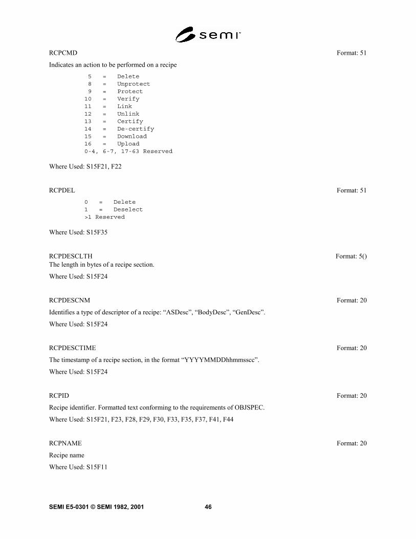
SEMI E5-0301 © SEMI 1982, 2001 46
RCPCMD Format: 51
Indicates an action to be performed on a recipe
5 = Delete8 = Unprotect9 = Protect
10 = Verify11 = Link12 = Unlink13 = Certify14 = De-certify15 = Download16 = Upload0-4, 6-7, 17-63 Reserved
Where Used: S15F21, F22
RCPDEL Format: 51
0 = Delete1 = Deselect>1 Reserved
Where Used: S15F35
RCPDESCLTH Format: 5()The length in bytes of a recipe section.
Where Used: S15F24
RCPDESCNM Format: 20
Identifies a type of descriptor of a recipe: “ASDesc”, “BodyDesc”, “GenDesc”.
Where Used: S15F24
RCPDESCTIME Format: 20
The timestamp of a recipe section, in the format “YYYYMMDDhhmmsscc”.
Where Used: S15F24
RCPID Format: 20
Recipe identifier. Formatted text conforming to the requirements of OBJSPEC.
Where Used: S15F21, F23, F28, F29, F30, F33, F35, F37, F41, F44
RCPNAME Format: 20
Recipe name
Where Used: S15F11

SEMI E5-0301 © SEMI 1982, 200147
RCPNEWID Format: 20
The new recipe identifier assigned as the result of a copy or rename operation.
Where Used: S15F19, F41, F44
RCPOWCODE Format: 11
Indicates whether any pre-existing recipe is to be overwritten (=TRUE) or not (=FALSE) on download.
Where Used: S15F27
RCPPARNM Format: 20
The name of a recipe variable parameter. Maximum length of 40 characters.
Where Used: S15F25, F33; S16F3, F11, F13, F15, F23
RCPPARRULE Format: 20
The restrictions applied to a recipe variable parameter setting. Maximum length of 80 characters.
Where Used: S15F25
RCPPARVAL Format: 10, 11, 20, 3(), 4(), 5()
The initial setting assigned to a recipe variable parameter. Text form restricted to maximum of 80 characters.
Where Used: S15F25, F33; S16F3, F11, F13, F15, F23
RCPRENAME Format: 11
Indicates whether a recipe is to be renamed (= TRUE) or copied (= FALSE).
Where Used: S15F19
RCPSECCODE Format: 10
Indicates the sections of a recipe requested for transfer or being transferred:
1 = Generic attributes only3 = Generic attributes and body4 = All agent-specific datasets (zero or more)7 = Generic attributes, body, and all agent-specific datasets8 = Single agent-specific dataset (zero or one)
11 = Generic attributes, body, and single agent-specific datasetsAll other values reserved
Where Used: S15F15, F16, F17
RCPSECNM Format: 20
Recipe section name: “Generic”, “Body”, or “ASDS”.
Where Used: S15F15, F18

SEMI E5-0301 © SEMI 1982, 2001 48
RCPSPEC Format: 20
Recipe specifier. The object specifier of a recipe.
Where Used: S15F1, F9, F13, F15, F17, F19, F27, F28, F31, F32, F45; S16F11, F13, F15, F23
RCPSTAT Format: 51
The status of a managed recipe
0 = Does not exist8 = Unprotected9 = Protected
Where Used: S15F10
RCPUPDT Format: 11
Indicates if an existing recipe is to be updated (= True) or a new recipe is to be created (= False).
Where Used: S15F13
RCPVERS Format: 20
Recipe version
Where Used: S15F10, F12
READLN Format: 3(), 5()
Maximum length to read
Where Used: S13F5
RECLEN Format: 3(), 5()
Maximum length of a Discrete record
Where Used: S13F4
REFP Format: 3()
Reference Point
Where Used: S12F1, F4
REPGSZ Format: 20, 3(), 5()
Reporting group size
Where Used: S2F23; S17F5

SEMI E5-0301 © SEMI 1982, 200149
RESC Format: 31, 51
Resolution code for numeric data
1 = Absolute. Value may be specified to nearest increment of RESV2 = Significant Digits. Value may be specified with no more significant
digits than RESV allows
Where Used: S7F22
RESPEC Format: 20
Object specifier for the recipe executor
Where Used: S15F29, F33, F35
RESV Format: 3(), 4(), 5()
Resolution value for numeric data
If RESC=1, then RESV contains smallest increment allowed for parameter
Where Used: S7F22
RIC Format: 31, 51
Reset code, 1 byte
0 = Not used1 = Power up reset>1 Other reset conditions2-63 Reserved
Where Used: S2F19
RMACK Format: 51
Conveys whether a requested action was successfully completed, denied, completed with errors, or will becompleted with notification to the requestor.
0 = Successful completion1 = Cannot perform action2 = Completed with errors3 = Action will be completed and notification sent4 = No request for this action exists
Where Used: S15F4, F6, F8, F10, F12, F14, F16, F18, F20, F22, F24, F25, F26, F28, F30, F32, F34, F36, F38, F40,F42, F44, F48

SEMI E5-0301 © SEMI 1982, 2001 50
RMCHGSTAT Format: 5()
Indicates the change that occurred for an object.
0 = No change1 = Created2 = Updated3 = Stored (new)4 = Replaced5 = Deleted6 = Copied (new object)7 = Renamed8 = Unprotected9 = Protected
10 = Verified11 = Linked12 = Unlinked13 = Certified14 = De-certified15 = Selected16 = Deselected
Where Used: S15F25
RMCHGTYPE Format: 5()
Indicates the type of change for a recipe.
0 = No change1 = Create2 = Update5 = Delete6 = Copy (new object)7 = Rename8 = Unprotect9 = Product
10 = Verify11 = Link12 = Unlink13 = Certify14 = De-certify15 = Change generic attribute16 = Change agent-specific attribute17 = Change both generic and agent-specific attributes
Where Used: S15F37, F41, F44, F46, F47, F48
RMDATASIZE Format: 5()
The maximum total length, in bytes, of a multi-block message, used by the receiver to determine if the anticipatedmessage exceeds the receiver’s capacity.
Where Used: S15F1

SEMI E5-0301 © SEMI 1982, 200151
RMGRNT Format: 10
Grant code, used to grant or deny a request. 1 byte.
0 = Permission granted1 = Cannot accept now, try again2 = No space3 = Request is on hold4-64 Reserved
Where Used: S15F2, F37, F46
RMNEWNS Format: 20
New name (identifier) assigned to a recipe namespace
Where Used: S15F5
RMNSCMD Format: 51
Action to be performed on a recipe namespace
1 = Created5 = Deleted0, 2-4, 6-63 Reserved
Where Used: S15F3
RMNSSPEC Format: 20
The object specifier of a recipe namespace.
Where Used: S15F3, F5, F7, F11, F21, F23, F25, F47
RMRECSPEC Format: 20
The object specifier of a distributed recipe namespace recorder.
Where Used: S15F39, F41, F43
RMREQUESTOR Format: 11
Set to TRUE if initiator of change request was an attached segment. Set to FALSE otherwise.
Where Used: S15F41, F44, F46
RMSEGSPEC Format: 20
The object specifier of a distributed recipe namespace segment.
Where Used: S15F37, F39, F41, F44, F46, F47
RMSPACE Format: 5()
The amount of storage available for at least one recipe in a recipe namespace, in bytes.
Where Used: S15F8

SEMI E5-0301 © SEMI 1982, 2001 52
ROWCT Format: 5()
Row count in die increments
Where Used: S12F1, F4
RPSEL Format: 51
Reference Point Select
Number of reference point from 0-n.
Where Used: S12F1, F4
RPTID Format: 20, 3(), 5()
Report ID
Where Used: S2F33, F35; S6F11, F13, F16, F11, F19, F21, F22; S17F1, F2, F3, F4, F5, F9, F11, F12
RPTOC Format: 11
A Trace Object attribute for a flag which, if set TRUE, causes only variables which have changed during the sampleperiod to be included in a report.
Where Used: S14F1, F2, F3, F4; S17F5
RQCMD Format: 11
Required Command
True = Command must be specifiedFalse = Command is optional
Where Used: S7F22
RQPAR Format: 11
Required Parameter
True = Parameter must be specifiedFalse = Parameter is optional
Where Used: S7F22

SEMI E5-0301 © SEMI 1982, 200153
RRACK Format: 10
Request to Receive Acknowledge code, 1 byte
0 = Acknowledge, OK (note that 'OK' differs from 'ready')1 = Invalid port number2 = Requested material is not at identified port3 = Busy. Try again4 = Sender does not have permission to perform this operation5-63 Reserved
Where Used: S4F18
RSACK Format: 10
Ready to Send Acknowledge code, 1 byte
0 = Acknowledge, OK (note that 'OK' differs from 'ready')1 = Invalid port number2 = Port is already occupied3 = Busy, unable to move material at this time. Try again4 = Receiver does not have permission to perform this operation5-63 Reserved
Where Used: S4F2
RSDA Format: 10
Request Spool Data Acknowledge
0 = OK1 = Denied, busy try later2 = Denied, spooled data does not exist3-63 Reserved
Where Used: S6F24
RSDC Format: 51
Request Spool Data Code
0 = Transmit Spooled Messages1 = Purge Spooled Messages2-63 Reserved
Where Used: S6F23
RSINF Format: 3()
Starting location for row or column. This item consists of 3 values (x,y,direction). If direction value is negative, it equals decreasing direction.If the value is positive, it equals increasing direction. Direction must bea non-zero value.
Where Used: S12F7, F14

SEMI E5-0301 © SEMI 1982, 2001 54
RSPACK Format: 10
Reset Spooling Acknowledge
0 = Acknowledge, spooling setup accepted1 = Spooling setup rejected2-63 Reserved
Where Used: S2F44
RTYPE Format: 3(), 5()
Type of record
0 = Stream1 = Discrete2-63 Reserved
Where Used: S13F4
SDACK Format: 10
Map set-up data acknowledge
0 = Received data>1 = Error1-63 Reserved
Where Used: S12F2
SDBIN Format: 10
Send bin information flag
0 = Sent bin information1 = Don't send bin information>1 = Error2-63 Reserved
Where Used: S12F17
SEQNUM Format: 3(), 5()
Command Number
Value which identifies a unique process program command by its position inthe list of commands relative to the first. For the first command of theprocess program, SEQNUM is l.
Where Used: S7F27
SFCD Format: 10
Status form code, 1 byte
Where Used: S1F5

SEMI E5-0301 © SEMI 1982, 200155
SHEAD Format: 10
Stored header related to the transaction timer
Where Used: S9F9
SLOTID Format: 51
Used to reference material by slot (a position that holds material/substrates) in a carrier. This item may beimplemented as an array in some messages.
Where used: S16F11, F13, F15
SMPLN Format: 3(), 5()
Sample number
Where Used: S6F1
SOFTREV Format: 20
Software revision code 6 bytes maximum
Where Used: S1F2, F13, F14; S7F22, F23, F26, F31
SPAACK Format: 10
Equipment acknowledgement code, 1 byte
0 = Everything correct1 = Invalid data>1 = Equipment-specific error2-63 Reserved
Where Used: S2F4
SPD Format: 10
Service program data
Where Used: S2F3, F6
SPID Format: 20
Service program ID, 6 characters
Where Used: S2F1, F5, F7, F9, F12; S9F13
SPNAME Format: 20
Service parameter name defined in specific standard. If service parameter is defined as an object attribute, this iscompletely the same as ATTRID except format restrictions above.
Where used: S14F19, F20, F21, F28

SEMI E5-0301 © SEMI 1982, 2001 56
SPR Format: Device Dependent
Service program results
Device dependent
Where Used: S2F10
SPVAL Format: 0, 10, 11, 20, 21, 3(), 5()
Service parameter value, corresponding to SPNAME. If service parameter is defined as an object attribute, this iscompletely the same as ATTRDATA except format restrictions for the attribute.
Where used: S14F19, F20, F21
SSACK Format: 20
Indicates the success or failure of a requested action. Two characters.
Where Used: S18F2, F4, F6, F8, F10, F12, F14
SSCMD Format: 20
Indicates an action to be performed by the subsystem.
Where Used: S18F13
STATUS Format: 20
Provides status information for a subsystem component. Used in the data item STATUSLIST.
Where Used: See STATUSLIST.
STATUSLIST Format: 0
A list of STATUS data sent in a fixed order. STATUSLIST has the following form:
L,s1. <STATUS
1>
.s. <STATUS
s>
Where used: S18F4, F8, F10, F12, F14
STEMP Format: 20
String template. ASCII text string acceptable to equipment as a parametervalue. A data string matches a template string if the data string is atleast as long as the template and each character of the data string matchesthe corresponding character of the template. A null list indicates alluser data is acceptable to the machine.
Where Used: S7F22

SEMI E5-0301 © SEMI 1982, 200157
STIME Format: 20
Sample time, 12 or 16 bytes
If 12 bytes the format is YYMMDDhhmmssYY=Year 00 to 99MM=Month 01 to 12DD=Day 01 to 31hh=Hour 00 to 23mm=Minute 00 to 59ss=Second 00 to 59If 16 bytes the format is YYYYMMDDhhmmssccYYYY=Year 0000 to 9999MM=Month 01 to 12DD=Day 01 to 31hh=Hour 00 to 23mm=Minute 00 to 59ss=Second 00 to 59cc=Centisecond 00 to 99
NOTE 4: The 16-byte format is currently optional. After January 1, 1998, the 16-byte format shall be required on new andupdated implementations. Support for the 12-byte format shall be supported as a configurable option using the equipmentconstant TimeFormat. This is a format requirement only and does not imply either precision or accuracy.
Where Used: S6F1
STRACK Format: 10
Spool Stream Acknowledge
1 = Spooling not allowed for stream (i.e., Stream 1)2 = Stream unknown3 = Unknown function specified for this stream4 = Secondary function specified for this stream
Where Used: S2F44
STRID Format: 51
Stream Identification
Where Used: S2F43, F44
STRP Format: 3()
Starting position in die coordinate position. Must be in (X,Y) order.
Where Used: S12F9, F16
SV Format: 0, 10, 11, 20, 21, 3(), 4(), 5()
Status variable value
Where Used: S1F4; S6F1

SEMI E5-0301 © SEMI 1982, 2001 58
SVCACK Format: 10
Service acceptance acknowledge code, 1 byte.
0 = Acknowledge, service has been performed1 = Service does not exist2 = Cannot perform now3 = At least parameter is invalid4 = Acknowledge, service will be performed with completion notified later
with parameters for response5 = Service is not completed or prohibited6 = No such object exists7-63 Reserved
Where used: S14F20
SVCNAME Format: 20
Service name provided on specified object asking by the host.
Where used: S14F19, F26, F27, F28
SVID Format: 20, 3(), 5()
Status variable ID
Status variables may include any parameter that can be sampled in time suchas temperature or quantity of a consumable.
Where Used: S1F3, F11, F12; S2F23
SVNAME Format: 20
Status Variable Name
Where Used: S1F12
TARGETID Format: 20
Description. Identifies where a request for action or data is to be applied. If text, conforms to OBJSPEC.
Where Used: S18F1, F3, F5, F7, F9, F11, F13
TARGETSPEC Format: 20
Object specifier of target object
Where Used: S14F17; S15F43
TBLACK Format: 51
Indicates success or failure
0 = Success1 = Failure
Where Used: S13F14, F16

SEMI E5-0301 © SEMI 1982, 200159
TBLCMD Format: 51
Provides information about the table or parts of the table being transferred or requested. Enumerated:
0 = Complete Table1 = New rows (add)2 = New columns (append)3 = Replace existing rows4 = Replace existing columns
Where Used: S13F13, F15
TBLELT Format: 0, 10, 11, 20, 21, 3(), 4(), 5()
Table element. The first table element in a row is used to identify the row.
Where Used: S13F13, F15, F16
TBLID Format: 20
Table identifier. Text conforming to the requirements of OBJSPEC.
Where Used: S13F13, F15, F16
TBLTYP Format: 20
A reserved text string to denote the format and application of the table. Text conforming to the requirements ofOBJSPEC.
Where Used: S13F13, F15, F16
TEXT Format: 10, 20, 22, 3(), 5()
A single line of characters
Where Used: S10F1, F3, F5, F9
TIAACK Format: 10
Equipment acknowledgement code, 1 byte
0 = Everything correct1 = Too many SVIDs2 = No more traces allowed3 = Invalid period>3 = Equipment-specified error4-63 Reserved
Where Used: S2F24

SEMI E5-0301 © SEMI 1982, 2001 60
TIACK Format: 10
Time Acknowledge Code, 1 byte
0 = OK1 = Error, not done2-63 Reserved
Where Used: S2F32
TID Format: 10
Terminal number, 1 byte
0 = Single or main terminal>0 = Additional terminals at the same equipment
Where Used: S10F1, F3, F5, F7
TIME Format: 20
Time of day, 12 or 16 bytes
If 12 bytes the format is YYMMDDhhmmssYY=Year 00 to 99MM=Month 01 to 12DD=Day 01 to 31hh=Hour 00 to 23mm=Minute 0000 to 9999ss=Second 00 to 59If 16 bytes the format is YYYYMMDDhhmmssccYYYY=Year 0000 to 9999MM=Month 01 to 12DD=Day 01 to 31hh=Hour 00 to 23mm=Minute 00 to 59ss=Second 00 to 59cc=Centisecond 00 to 99
NOTE 5: The 16-byte format is currently optional. After January 1, 1998, the 16-byte format shall be required on new andupdated implementations. Support for the 12-byte format shall be supported as a configurable option using the equipmentconstant TimeFormat. This is a format requirement only and does not imply either precision or accuracy.
Where Used: S2F18, F31
TIMESTAMP Format: 20
A text string indicating the time of an event, which encodes time in the following format:
YYYYMMDDhhmmssccYYYY = year 0000 to 9999MM = month 01 to 12DD = day 01 to 31hh = hour 00 to 23mm = minute 00 to 59ss = second 00 to 59cc = centisecond 00 to 99
Where Used: S5F9, F11, F15; S15F41, F44; S16F5, F7, F9

SEMI E5-0301 © SEMI 1982, 200161
TOTSMP Format: 20, 3(), 5()
Total samples to be made
Where Used: S2F23; S17F5
TRACK Format: 11
Tells whether the related transfer activity was successful (=True) or unsuccessful (=False).
Where Used: S4F20, F22, F23
TRATOMICID Format: 5()
Equipment assigned identifier for an atomic transfer
Where Used: S4F20
TRAUTOD Format: 11
A Trace Object attribute for a control flag which, if set TRUE, causes the Trace Object to delete itself when it hascompleted a report.
Where Used: S14F1, F2, F3, F4; S17F5
TRAUTOSTART Format: 11
For each atomic transfer, this data item tells the equipment if it should automatically start the handoff when ready(=TRUE) or await the host's "StartHandoff" command (=FALSE) following setup. This data item only affects theprimary transfer partner.
Where Used: S4F19
TRCMDNAME Format: 20
Identifier of the transfer job-related command to be executed. Possible values:
"CANCEL" "PAUSE" "RESUME" "ABORT" "STOP" "STARTHANDOFF" (requires a TRATOMICID as a parameter)
Where Used: S4F21
TRDIR Format: 51
Direction of handoff.
1 = Send material2 = Receive material0, 3-63 Reserved
Where Used: S4F19, F29

SEMI E5-0301 © SEMI 1982, 2001 62
TRID Format: 20, 3(), 5()
Trace request ID
Where Used: S2F23; S6F1, F27, F28; S17F5, F6, F7, F8, F13, F14
TRJOBID Format: 10
Equipment assigned identifier for the transfer job.
Where Used: S4F20, F21
TRJOBMS Format: 51
Milestone for a transfer job (e.g., started or complete).
1 = Transfer Job Started2 = Transfer Job Complete0, 3-63 Reserved
Where Used: S4F23
TRJOBNAME Format: 20
Host assigned identifier for the transfer job. Limited to a maximum of 80 characters.
Where Used: S4F19, F23
TRLINK Format: 5()
Common identifier for the atomic transfer used by the transfer partners to confirm that they are working on the samehost-defined task.
Where Used: S4F19, F29, F31, F33, F39
TRLOCATION Format: 5()
Identifier of the material location involved with the transfer. For one transfer partner, this will represent thedesignated source location for the material to be sent. For the other transfer partner, it will represent the designateddestination location for the material to be received.
Where Used: S4F19, F29
TROBJNAME Format: 20
Identifier for the material (transfer object) to be transferred
Where Used: S4F19, F23, F29
TROBJTYPE Format: 5()
Type of object to be transferred
Where Used: S4F19, F29

SEMI E5-0301 © SEMI 1982, 200163
TRPORT Format: 5()
Identifier of the equipment port to be used for the handoff
Where Used: S4F19, F29
TRPTNR Format: 20
Name of the equipment which will serve as the other transfer partner for this atomic transfer. This corresponds toEQNAME.
Where Used: S4F19, F29
TRPTPORT Format: 5()
Identifier of the transfer partner's port to be used for the transfer.
Where Used: S4F19, F29
TRRCP Format: 20
Name of the transfer recipe for this handoff. Limited to a maximum of 80 characters.
Where Used: S4F19
TRROLE Format: 51
Tells whether the equipment is to be the primary or secondary transfer partner.
1 = Primary Transfer Partner2 = Secondary Transfer Partner
Where Used: S4F19, F29
TRSPER Format: 4()
A Trace Object attribute which holds the value for sampling interval time.
Where Used: S14F1, F2, F3, F4; S17F5
TRTYPE Format: 51
Tells whether the equipment is to be an active or passive participant in the transfer.
1 = Active2 = Passive
Where Used: S4F19, F23, F29

SEMI E5-0301 © SEMI 1982, 2001 64
TSIP Format: 10
Transfer status of input port, 1 byte
1 = Idle state2 = Prep state3 = Track on state4 = Stuck in Receiver state5-63 Reserved
Where Used: S1F10
TSOP Format: 10
Transfer status of output port, 1 byte
1 = Idle state2 = Prep state3 = Track on state4 = Stuck in Sender state5 = Completion state6-63 Reserved
Where Used: S1F10
TTC Format: 3(), 5()
Time to completion
Where Used: S3F4
ULIM Format: 3(), 4(), 5()
Upper limit for numeric value
Where Used: S7F22
UNFLEN Format: 3(), 5()
Unformatted Process Program Length
If greater than zero, indicates PPID is available as an unformatted processprogram and its length in bytes. If zero, the PPID is not available as anunformatted process program. Negative values are invalid.
Where Used: S7F34
UNITS Format: 20
Units Identifier
As allowed by SEMI E5 Section 9
Where Used: S1F12; S2F30, F48; S7F22

SEMI E5-0301 © SEMI 1982, 200165
UPPERDB Format: 11, 20, 3(), 4(), 5()
A variable limit attribute which defines the upper boundary of the deadband of a limit. The value applies to a singlelimit (LIMITID) for a specified VID. Thus, UPPERDB and LOWERDB as a pair define a limit.
Where Used: S2F45, F48
V Format: 0, 10, 11, 20, 21, 3(), 4(), 5()
Variable data
Where Used: S6F11, F13, F16, F20, F22
VID Format: 20, 3(), 5()
Variable ID
Where Used: S2F33, F45, F46, F47, F48; S6F13, F18, F22; S17F1
VLAACK Format: 10
Variable Limit Attribute Acknowledge Code, 1 byte
0 = Acknowledge, command will be performed1 = Limit attribute definition error2 = Cannot perform now>2 = Other equipment-specific error3-63 Reserved
Where Used: S2F46
XDIES Format: 4(), 5()
X-axis die size (index)
Where Used: S12F1, F4
XYPOS Format: 3()
X and Y Coordinate Position. Must be in (X,Y) order
Where Used: S12F11, F18
YDIES Format: 4(), 5()
Y-axis die size (index)
Where Used: S12F1, F4
6.7 Variable Item Dictionary — This section defines variable data items which are available to the Host for datacollection purposes.Name: A unique mnemonic name for this variable data item. This name is provided for reference only.

SEMI E5-0301 © SEMI 1982, 2001 66
Class: The data type classification (SV, ECV, or DVVAL) of the item. Status values (SV's) always contain validinformation, while data values (DVVAL's) may only be valid upon the occurrence of a particular event. Allequipment constants (ECV's) are settable by the Host.
Format: The allowable item format codes which can be used for this variable data item. ...as in Data ItemDictionary...
Description: A description of the variable data item, with the meanings of specific values. Also, specify validity foritem of class DVVAL.
AlarmID Format: 3(), 5()
Class: DVVAL
This variable is valid only upon the setting or clearing of an alarm condition and contains the current alarmidentification (ALID), regardless of whether that alarm is enabled for reporting.
AlarmsEnabled Format: 0
Class: SV
Contains the list of alarms (ALIDs) enabled for reporting (via Stream 5).
Structure: L,n n= # of alarms enabled
1.<ALID1>..n.<ALIDn>
AlarmsSet Format: 0
Class: SV
Contents of this variable is a list of alarms (ALIDs) currently in the UNSAFE (alarm set) state, regardless ofwhether the alarms are enabled for reporting.
Structure: L,n n= # of alarms set
1.<ALID1>..n.<ALIDn>
ARAMSAccumReset Format: 20
Class: SV
The timestamp of when the set of accumulators EngTime, InterruptionCtr, PrdTime, NSTime, SbyTime, SDTime,and UDTime were reset to zero. Uses format defined for CLOCK.
ARAMSInfo Format: 20
Class: SV
Text field set by the equipment to provide additional information concerning an ARAMS state change.

SEMI E5-0301 © SEMI 1982, 200167
ARAMSState Format: 20
Class: SV
The ARAMS code corresponding to the current state/substate. Four characters.
ARAMSText Format: 20
Class: SV
Text describing the ARAMSState. 3-80 characters.
ARAMSTimeStamp Format: 20
Class: SV
The timestamp of the last ARAM state change. This is a format requirement only and does not imply precision oraccuracy. Uses format defined for CLOCK.
CLOCK Format: 20
Class: SV
The value of the equipment's internal clock. This is a format requirement only and does not imply precision oraccuracy.
Format: YYYYMMDDhhmmssccYYYY = Year 0000 to 9999MM = Month 01 to 12DD = Day 01 to 31hh = Hour 00 to 23mm = Minute 00 to 59ss = Second 00 to 59cc = centisecond 00 to 99
ControlState Format: 10, 51
Class: SV
This status variable contains the code which identifies the current control state of the equipment. When reportedrelated to a control state transition, its value should represent the state current after the transition.
1 = OFF-LINE/EQUIPMENT OFF-LINE2 = OFF-LINE/ATTEMPT ON-LINE3 = OFF-LINE/HOST OFF-LINE4 = ON-LINE/LOCAL5 = ON-LINE/REMOTE6-63 Reserved
CycleCtr Format: 5()
Class: SV
The number of machine cycles during the lifetime of the equipment. Non-resettable.

SEMI E5-0301 © SEMI 1982, 2001 68
DowntimeAlarm Format: 3(), 5()
Class: SV
Identifier of the last alarm or exception triggering an equipment-initiated transition to UNSCHEDULEDDOWNTIME from the PRODUCTIVE or STANDBY states.
DowntimeAlarmText Format: 20
Class: SV
Text associated with DowntimeAlarm. 0-80 characters.
DowntimeData Format: 20
Class: SV
Equipment defined data associated with transitions to, or within, the SCHEDULED or UNSCHEDULEDDOWNTIME states. For example, this may be used to carry fault information, the component serial number of arepaired component, or comments entered at the equipment’s control panel. 0-256 characters.
EngTime Format: 5()
Class: ECV
Accumulation of time in ENGINEERING reported in minutes.
EqpModel Format: 20
Class: SV
Text string describing the equipment model. 1-80 characters.
EqpName Format: 20
Class: ECV
Text string containing a user-assigned name for equipment. 1-80 characters. Information in the data item EQNAMEis a subset of EqpName.
EqpSerialNum Format: 20
Class: SV
Text string describing the product serial number assigned by the manufacturer. 1-80 characters. Information in thedata item MDLN is a subset of EqpSerialNum.
EstablishCommunicationsTimeout Format: 52
Class: ECV
The length of time, in seconds, of the interval between attempts to send S1F13 when establishing communications.

SEMI E5-0301 © SEMI 1982, 200169
EventsEnabled Format: 0
Class: SV
Contains the list of events (CEIDs) enabled for reporting (via Stream 6).
Structure: L,n n= # of events enabled
1.<CEID1>..n.<CEIDn>
EventLimit Format: 0, 10, 11, 20, 21, 3(), 4(), 5()
Class: DVVAL
Used with the Limits Monitoring capability, it contains the LIMITID of the limit reached or crossed byLimitVariable. Since multiple zone transitions for a variable may occur simultaneously (e.g., due to identical limitdefinitions or a slow data sampling rate), EventLimit has been defined to allow for a list of LIMITIDs.
InterruptionCtr Format: 5()
Class: ECV
The number of transitions to UNSCHEDULED DOWNTIME from PRODUCTIVE.
LastPowerdown Format: 20
Class: SV
Timestamp estimate of when the last powerdown or reset occurred. Uses format defined for Clock.
LimitVariable Format: 5()
Class: DVVAL
This variable contains the VID for the variable whose value changed monitoring zones.
MaxSpoolTransmit Format: 54
Class: ECV
The maximum number of messages which the equipment will transmit from the spool in response to an S6,F23"Transmit Spooled Messages" request. If MaxSpoolTransmit is set to zero, no limit is placed on the messages sentfrom the spool. Multi-block inquire/grant messages are not counted in this total.
NSTime Format: 5()
Class: ECV
Accumulation of time in NON-SCHEDULED TIME, reported in minutes.

SEMI E5-0301 © SEMI 1982, 2001 70
OperatorCommand Format: 5()
Class: DVVAL
This data variable is valid in the event the operator issues a command to the equipment. The codes for this variableare equipment-dependent.
OverWriteSpool Format: 11
Class: ECV
This Equipment Constant is used to indicate to the equipment either to overwrite data in the spool area or to stopspooling whenever the spool area limits are exceeded.
= TRUE to overwrite spooled data= FALSE to stop spooling when limits exceeded
PowerdownTime Format: 20
Class: SV
This timestamp is periodically updated based on an interval set by the user. It is used to determine the approximatetime that the equipment went down in the event of a power loss. Uses format defined for CLOCK.
PowerupState Format: 20
Class: SV
Specifies the powerup ARAMS state when powerdown occurs during manufacturing time. Single text digit: "2" =STANDBY, "5" = UNSCHEDULED DOWNTIME.
PPChangeName Format: 10, 20
Class: DVVAL
The PPID which was affected upon the event of the creation, editing, or deletion of a Process Program local to theequipment. If the PPID Data Item is also defined and implemented for the equipment, then the values forPPChangeName are subject to the same format restrictions defined for the PPID Data Item.
PPChangeStatus Format: 51
Class: DVVAL
The action taken on the Process Program named in PPChangeName. This variable is valid upon the event of thecreation, editing, or deletion of a Process Program local to the equipment.
1 = Credited2 = Edited3 = Deleted4-63 Reserved
PPError Format: 20
Class: SV or DVVAL
Contains information about a failure to verify a text process program.

SEMI E5-0301 © SEMI 1982, 200171
PPExecName Format: 0, 10, 20
Class: SV
The PPID(s) of the currently selected Process Program(s). The selection of a new Process Program updates thisvariable. If multiple Process Programs can be selected, then this variable is a list of PPIDs. If the PPID Data Item isalso defined and implemented for the equipment, then the values for PPExecName are subject to the same formatrestrictions defined for the PPID Data Item.
PPFormat Format: 51
Class: SV
Indicates the type or types of process programs and recipes that are supported.
1 = Unformatted process programs2 = Formatted process programs3 = Both unformatted and formatted process programs4 = Execution Recipes>4 Reserved
PrdRecovery Format: 11
Class: ECV
A boolean value that enables (TRUE) or disables (FALSE) the equipment-initiated return to PRODUCTIVE fromUNSCHEDULED DOWNTIME.
PrdState Format: 20
Class: SV
Default ARAMS Substate Code for automated transitions to PRODUCTIVE.
PrdTime Format: 5()
Class: ECV
Accumulation of time in PRODUCTIVE, reported in minutes.
PrevARAMSState Format: 20
Class: SV
The ARAMS code corresponding to the previous state/substate. Four characters.
PreviousProcessState Format: 51
Class: SV
The previous processing state of the equipment, before the most recent process state change.
0-63 Reserved

SEMI E5-0301 © SEMI 1982, 2001 72
ProcessState Format: 51
Class: SV
The current processing state of the equipment.
0-63 Reserved
RcpChangeName Format: 20
Class: DVVAL
The identifier of the recipe affected upon the event of the creation, editing, or deletion of a recipe.
RcpChangeStatus Format: 51
Class: DVVAL
The type of change that occurred for the recipe indicated in RcpChangeName
0 = No change1 = Created2 = Updated (modified)3 = Stored (new)4 = Replaced5 = Deleted6 = Copied7 = Renamed8,9 Reserved>10 Reserved
RcpExecName Format: 0, 20
Class: SV
The identifier, or a list of identifiers, of currently selected recipes. A zero-length item or list indicates no recipes arecurrently selected.
SbyRecovery Format: 11
Class: ECV
A boolean value that enables (TRUE) or disables (FALSE) the equipment-initiated return to STANDBY fromUNSCHEDULED DOWNTIME.
SbyTime Format: 5()
Class: ECV
Accumulation of time in STANDBY, reported in minutes.
SDTime Format: 5()
Class: ECV
Accumulation of time in SCHEDULED DOWNTIME, reported in minutes.

SEMI E5-0301 © SEMI 1982, 200173
SpoolCountActual Format: 5()
Class: SV
Used to keep a count of the messages actually contained in the equipment's spool area. Multi-block inquire/grantmessages are not spooled and not included in this count.
SpoolCountTotal Format: 5()
Class: SV
Used to keep a count of the total number of primary messages directed to the spool, regardless of whether placed orretained in the spool. Multi-block inquire/grant messages are not spooled and not included in this count.
SpoolFullTime Format: 20
Class: SV
Contains the timestamp from the time the spool last became full. If the spool was not filled during the last spoolingperiod, this will contain a time value prior to the current SpoolStartTime. Uses the same format as the CLOCKvariable data item.
SpoolStartTime Format: 20
Class: SV
Contains the timestamp from the time spooling last became active. Uses the same format as the CLOCK variabledata item.
SymptomID Format: 5()
Class: SV
A numeric code representing the symptom that initiated the user-initiated state change. A value of zero indicates "nosymptom".
SymptomText Format: 20
Class: SV
Text describing the SymptomID. 0-80 characters.
TimeFormat Format: 5()
Class: ECV
NOTE 6: The setting of this ECV controls whether the equipment shall send the Data Items STIME and TIME in 12 or 16-byteformat.
0 = 12-byte format1 = 16-byte format>1 Reserved

SEMI E5-0301 © SEMI 1982, 2001 74
TransitionType Format: 10
Class: DVVAL
Used with the Limits Monitoring capability, it defines the direction of the zone transition which has occurred.
0 = Transition from lower to upper zone.1 = Transition from upper to lower zone.
TRATID Format: 5()
Class: DVVAL
Contains the TRATOMICID of the atomic transfer referenced by the event.
TRJOBIDENT Format: 5()
Class: DVVAL
Contains the TRJOBID for the transfer job referenced by the event.
TRJOBNM Format: 20
Class: DVVAL
Contains the TRJOBNAME for the transfer job referenced by the event.
TRLNK Format: 5()
Class: DVVAL
Contains the TRLNK value for the atomic transfer referenced by the event.
UDTime Format: 5()
Class: ECV
Accumulation of time in UNSCHEDULED DOWNTIME, reported in minutes.
6.8 Object Dictionary — This sec tion defines the public attributes of objects which are available through SECS-IImessages.The attributes of an object are defined in a table for each object in the following form:
Agent Attribute Definition
Attribute Name Definition Access Format Value
“ObjType” Agent object type. RO 20 “Agent”“ObjID” The agent’s name, assigned by an authorized user. RO 20
Agent-Specific Dataset Object Attribute Definition
Attribute Name Definition Access Format Value
“ObjType” The object type. RO 20 “MRcpASDS”“ObjID” The object’s identifier. Contains the value in
AgentSpec Agent.RO 20

SEMI E5-0301 © SEMI 1982, 200175
“AgentSpec_Agent” The name of the executing agent to which the otherattributes in the dataset apply. Mandatory.
RO 20
“AgentSpec_AttrLength” The length of the agent-specific attributes, in bytes.Mandatory.
RO 54
“AgentSpec_ChgTime” Timestamp of when an agent-specific attribute was lastchanged. Mandatory.
RO 20
“AgentSpec_Comments” Comments specific to the agent entered by the author. RW 20 Maximum length is 80characters.
“AgentSpec_LinkParam” A list of variable parameter definitions modified fromthe list in LinkParam. Valid only for a linked mainrecipe. Parameter name and form may not be changed.
RO 00 List of structures composedof parameter name, value,and restrictions.
“Certified” The certification level for the specific agent, assignedby an authorized user. Reset when AgentSpecLinkParam is modified. Required for certificationsupport.
RW 52
“AgentSpec_UD_” Non-standard attribute defined by the supplier or user.Asterisk indicates the part of the attribute name that isprovided in this definition. Must be preserved exactlyexcept by the defining entity.
RO 10, 1120, 3()4(), 5()
Text form is limited to 80characters.
Carrier Attribute Definition
Attribute Name Definition Access Format Value
“ObjType” Object type. RO 20 A[7] = “Carrier”“ObjID” Object identifier for Carrier.
Same as CarrierID.RO 20 A[1-80] (Conforms to restrictions of ObjID
as specified in SEMI E39.1, Section 6.)“Capacity” Maximum number of substrates
in carrier.RO 51 Positive integer.
Examples: 1, 13, and 25.“CarrierIDStatus” Current state of the carrier ID
verification.RO 51 Enumerated.
“ContentMap” Ordered list of substrateidentifiers, corresponding to slot1, 2, …,n.
RO 0 L,n
1. <MID1>...
n. <MIDn>“CarrierProcessingStatus” The current processing state of
the material contained in thecarrier.
RO 51 Enumerated.
“LocationID” Identifier of current location. RO 20 A[1-80] (Conforms to restrictions of ObjIDas specified in SEMI E39.1, Section 6.)
“SlotMap” List of slot statuses as read bythe equipment.
RO 0 List of 1 to n where n is less than or equal tothe value of “Capacity”:L,n 1. <Slot Status 1> . . n. <Slot Status n>where “Slot Status” is enumerated as: 0 = UNDEFINED 1 = EMPTY 2 = NOT EMPTY 3 = NORMAL 4 = DOUBLE SLOTTED 5 = CROSS SLOTTED
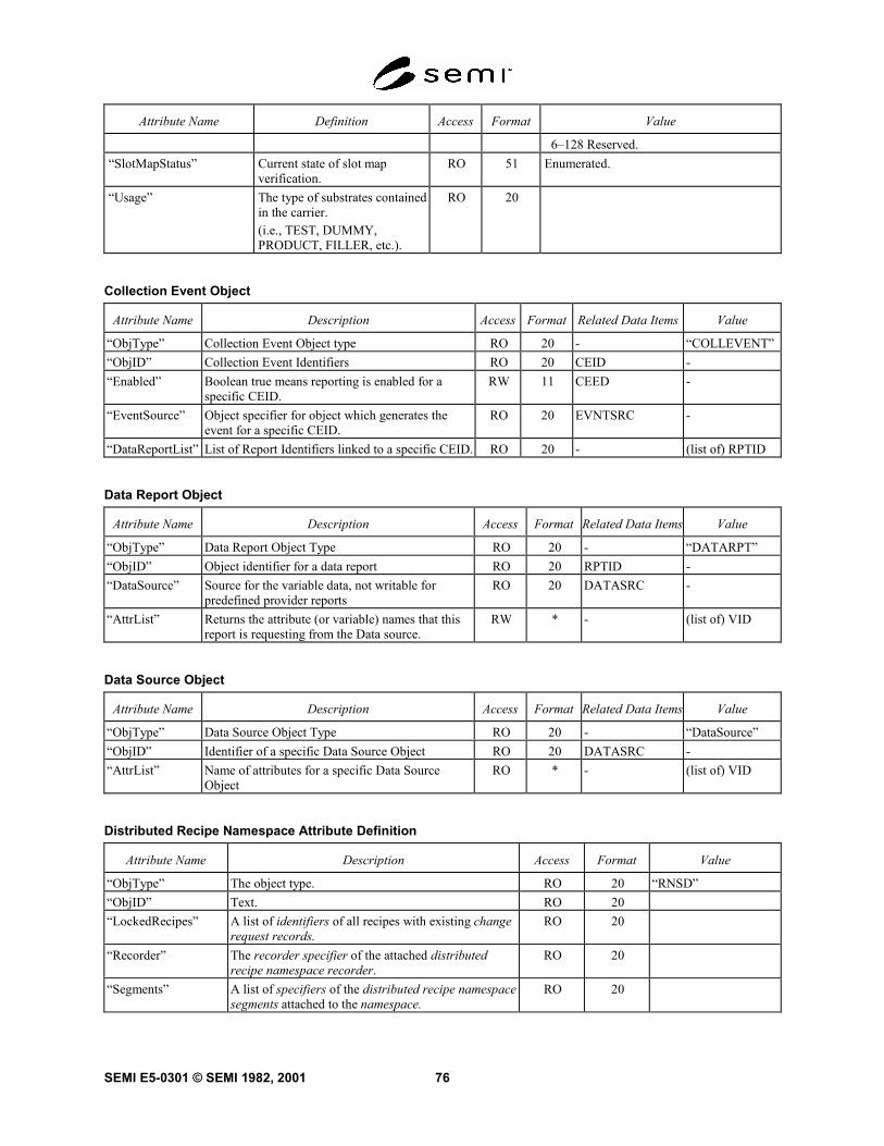
SEMI E5-0301 © SEMI 1982, 2001 76
Attribute Name Definition Access Format Value
6–128 Reserved.“SlotMapStatus” Current state of slot map
verification.RO 51 Enumerated.
“Usage” The type of substrates containedin the carrier.(i.e., TEST, DUMMY,PRODUCT, FILLER, etc.).
RO 20
Collection Event Object
Attribute Name Description Access Format Related Data Items Value
“ObjType” Collection Event Object type RO 20 - “COLLEVENT”“ObjID” Collection Event Identifiers RO 20 CEID -“Enabled” Boolean true means reporting is enabled for a
specific CEID.RW 11 CEED -
“EventSource” Object specifier for object which generates theevent for a specific CEID.
RO 20 EVNTSRC -
“DataReportList” List of Report Identifiers linked to a specific CEID. RO 20 - (list of) RPTID
Data Report Object
Attribute Name Description Access Format Related Data Items Value
“ObjType” Data Report Object Type RO 20 - “DATARPT”“ObjID” Object identifier for a data report RO 20 RPTID -“DataSource” Source for the variable data, not writable for
predefined provider reportsRO 20 DATASRC -
“AttrList” Returns the attribute (or variable) names that thisreport is requesting from the Data source.
RW * - (list of) VID
Data Source Object
Attribute Name Description Access Format Related Data Items Value
“ObjType” Data Source Object Type RO 20 - “DataSource”“ObjID” Identifier of a specific Data Source Object RO 20 DATASRC -“AttrList” Name of attributes for a specific Data Source
ObjectRO * - (list of) VID
Distributed Recipe Namespace Attribute Definition
Attribute Name Description Access Format Value
“ObjType” The object type. RO 20 “RNSD”“ObjID” Text. RO 20“LockedRecipes” A list of identifiers of all recipes with existing change
request records.RO 20
“Recorder” The recorder specifier of the attached distributedrecipe namespace recorder.
RO 20
“Segments” A list of specifiers of the distributed recipe namespacesegments attached to the namespace.
RO 20

SEMI E5-0301 © SEMI 1982, 200177
Distributed Recipe Namespace Manager Attribute Definition
Attribute Name Description Access Format Value
“ObjType” The object type. RO 20 “RNS_MgrD”“ObjID” The manager’s name. RO 20
Distributed Recipe Namespace Recorder Attribute Definition
Attribute Name Description Access Format Value
“ObjType” The object type. RO 20 “RNSDRecorder”“ObjID” Text. RO 20“LockedRecipes” List of identifiers of recipes with existing change
request records.RO 00
“Namespace” Identifies the namespace to which the recorder isattached. May be set by the manager.
RO 20
“NamespaceManager” Identifies the distributed recipe namespacemanager. May be set by the manager.
RO 20
“Segments” List of specifiers of currently attached segments. RO 00
Distributed Recipe Namespace Segment Attribute Definition
Attribute Name Description Access Format Value
“ObjType” The object type. RO 20 “RNSDSegment”“ObjID” The object name (identifier). RO 20“Namespace” The name (ObjID) of the namespace to which the
segment belongs. May be set by the manager.RO 20
“NamespaceManager” Identifies the distributed recipe namespacemanager. May be set by the manager.
RO 20
“RecipeReadOnlyLevel” Used to track the corresponding attribute of thenamespace to which the segment belongs. May beset by the manager.
RO 52

SEMI E5-0301 © SEMI 1982, 2001 78
Exception Attributes
Attribute Name Description Access Format Related Data Items Value
“ObjType” The object type RO 20 - “EXCEPTION”“ObjID” The identifier of a specific
ExceptionRO 20 EXID -
“EXType” Identifies the type of exception RO 20 - Select from set:“ALARM”“ERROR”
“EXMessage” Text message describing theabnormal situation monitored.
RO 20 - Max. length of 80 characters
“EXEnabled” Indicates that reporting to thedecision authority on the exceptioncondition is enabled.
RW 11 - Boolean;TRUE is enabled.
“EXRecoveryAction” List of possible recovery actions(EXRecovery).
RO 20 - list of text
“EXState” Current state of an ExceptionObject. The Exception Object stateis usually defined as a combinationof substates and concurrent states.
RO 20 - Composed from the set:“CLEARED”“SET”“NOTPOSTED”“POSTED”“NOTRECOVERING”“RECOVERING”“ABORTINGRECOVERY”
Execution Recipe Attribute Definition
Attribute Name Definition Acc. Rqmt Form Default Value
Identification Attributes“ObjType” The object type. RO Y Text: “ERcp” “ERcp”“ObjID” An identifier derived from Namespace,
Class, Name, and Version.RO Y Formatted text. -
“Namespace” The name of the originating namespace. RO Y Text. -“Name” A logical name assigned by the user when
the recipe is created.RO Y Text. -
“Class” The recipe’s class (e.g., “/PROCESS/”OR “/PROCESS/LOADER/”).
RO Y Formatted text:“CLASS/CLASS/../CLASS/”
-
“Version” The version of the recipe. RO Y Text. -Mandatory Attributes“ExecAttrLength” The length attribute for the attributes of
the execution recipe. Calculated when therecipe is downloaded and whenever anattribute changes. Mandatory.
RO Y Unsigned integer -
“ExecChgTime” The timestamp of a change to theattributes of the execution recipe.Mandatory.
RO Y Formatted text, timestampformat
-
“AttrLength” Preserved. Mandatory. RO Y Unsigned integer -“AttrChgTime” Preserved. Mandatory. RO Y Timestamp format -“EditTime” Preserved unless recipe is modified.
Timestamp of when the body was createdor modified. Mandatory.
RO Y Formatted text Timestampformat
-

SEMI E5-0301 © SEMI 1982, 200179
Attribute Name Definition Acc. Rqmt Form Default Value
“BodyLength” Preserved unless recipe is modified.Length of the recipe’s body, in bytes.Mandatory.
RO Y Unsigned integer -
“BodyFormat” Indicates the form and format of therecipe’s body.
RO Y Enumerated unsignedinteger:0 = source,1 = object,> 1 reserved.
0
“Verified” Indicates whether the recipe’s body issyntactically correct.
RO Y Boolean. FALSE
“Linked” Indicates whether the recipe is linked. RO Y Boolean. FALSE“ChangedBody” Set to TRUE if the recipe body has
changed without a subsequent upload tothe originating namespace. Note: thisattribute is never updated to a namespace.Required only if recipe can be changed orcreated.
RO Y Boolean. FALSE
“ExecChgCtl” Preserved. Specifies change controlrequirements for recipe.
RO Y Binary.Bitwise:1 - may change2 - change notificationrequired4 - recipe may be selectedafter change,8 - most recent parametersettings shall be saved.Any combination of thesefour bits is allowed.
0
Optional Attributes“AgentSpec_Comments”
Copied from the original agent-specificattribute when downloaded. Set by theuser.
RO N Text. Maximum length is80 characters.
-
“ApprovalLevel” Indicates the level of approval assignedby an authorized user.
RO N Unsigned integer 0
“Certified” Preserved from the agent-specificattribute as downloaded. May be used ascontrol for production-worthy recipes.
RO N Unsigned integer 0
“Comments” User comments. Preserved from thegeneric attribute as downloaded.
RO N Text. Maximum length is80 characters.
-
“EditedBy” Preserved unless recipe is modified. Thename of the person or executing agentwho last modified the recipe.
RO N Text. Maximum length is40 characters.
-
“EstRunTime” The nominal or estimated execution (run)time of the recipe, in seconds. Used forscheduling purposes. Preserved from thegeneric attribute as downloaded.
RO N Unsigned integer 0
“ExecLinkParam” Preserved unless last value is changed(Section 6.7.4). Contains the list ofparameter definitions including anyagent-specific modifications. Required forvariable parameter support.
RO N Structure composed ofparameter name, initialvalue, and restrictions.
NULL
“LinkList” Preserved. A complete list of recipespecifiers for a linked recipe set. Requiredfor multi-part recipe support.
RO N List of formatted text. NULL

SEMI E5-0301 © SEMI 1982, 2001 80
Attribute Name Definition Acc. Rqmt Form Default Value
“SrcRcpID” For a derived object form recipe, containsthe recipe identifier of the original sourceform recipe. Required only for derivedobject form recipes.
RO N Formatted text. NULL
“VerificationID” Identification code used by the verifier ofthe recipe. May be used to determine out-of-date formats that need to be re-verified.
RO N Text. Maximum length is40 characters.
NULL
Non-Standard AttributesAgentSpec_UD_* Preserved from the original agent-specific
attributed as downloaded.RO N Defined by supplier or
user. Text limited to 80characters.
-
UD_* Non-standard attribute defined bysupplier or user. Asterisk indicates thepart of the attribute name that is providedin this definition. Shall be preservedexactly except by the entity that definedit.
RO N Varies with definition.Text form is limited to 80characters.
-
Managed Recipe Attribute Definition
Attribute Name Description Access Format Value
“ObjType” The object type. RO 20 “MRcp”“ObjID” An identifier derived from Class, Name, and
Version. No part of a recipe’s identifier shall bechanged except through renaming.
RO 20
(other) Description of the information contained. ROor
RW
Varies withdefinition.
Varies with definition.
“Name” A logical name assigned by the user when therecipe is created or renamed.
RO 20
“Class” The recipe’s class (e.g., “/PROCESS/” or“/PROCESS/LOADER/”).
RO 20 Formatted text:“CLASS/CLASS/../CLASS/”
“Version” The version of the recipe. RO 20“AttrLength” The total length of the generic attributes, in bytes.
Mandatory.RO 5()
“AttrChgTime” Timestamp of the last change to a generic attribute.Mandatory.
RO 20
“BodyLength” Length of the recipe’s body, in bytes. Mandatory. RO 5()“EditTime” Timestamp of when the body was created or last
updated. Mandatory.RO 20 Timestamp format:
“YYYYMMDDhhmmsscc”“BodyFormat” Indicates the form and format of the recipe’s body.
Default is zero.RO 52 0 = source,
1 = object,>1 reserved.
“Verified” Indicates whether the recipe’s body is syntacticallycorrect. Reset when the recipe is created orupdated. Default is FALSE.
RO 11
“Linked” Indicates whether the recipe is linked. Reset whenthe recipe is originated, verified, or unlinked.Default is FALSE.
RO 11
“ApprovalLevel” Indicates the level of approval assigned by anauthorized user. Default is zero. Reset when therecipe is originated or linked. For a linked recipe,may not be higher than any of its subrecipes.
RW 52

SEMI E5-0301 © SEMI 1982, 200181
Attribute Name Description Access Format Value
“Comments” User comments. RW 20 Maximum length is 80 characters.“EditedBy” The name of the person who last edited the recipe. RO 20 Maximum length is 40 characters.“EstRunTime” The nominal or estimated execution (run) time of
the recipe, in seconds. Reset when the recipe, iscreated or updated. Set when the recipe is verified.May be recalculated to total time for a main recipewhen linked. Used for scheduling purposes.Algorithm for calculation shall be documented.Default is 0.
RW 54
“ExecChgCtrl” Specifies change control requirements for recipe.Default is 0. Combinations of bits are used toindicate multiple permissions.
RW 10 Binary.Bitwise (MSB = 8):1 - the recipe body may be changed2 - change notification required4 - recipe may be selected afterchange,8 - most recent parameter settingsshall be saved.Any combination of these four bitsis allowed
“ExtRef” A list of all recipe specifiers as referenced withinthe recipe. Explicit versions not required. Resetwhen the recipe is created, updated, and verified.
RO 00 List of items of format 20.
“LinkList” A complete list of recipe specifiers found in theExtRef attribute of a main recipe and all of itssubrecipes, with duplicates removed and allversions explicitly determined. Set for the mainrecipe when linked. Reset when the recipe isoriginated or verified. Required for multi-partrecipe support.
RO 00 List of items of format 20.
“LinkParam” A list of all variable parameter definitionscontained in the Parameters attribute of a mainrecipe and all of its subrecipes, with duplicatesremoved. Reset when the recipe is created,updated, or verified. Set when the recipe is linked.Required for variable parameter support.
RO 00 List of parameter definitionstructures composed of parametername, initial value, and restrictions.
“Parameters” A list of variable parameter definitions contained inthe recipe. Reset when the recipe is created,updated, and verified. Set when the recipe isverified. Required only for variable parametersupport.
RO 00 List of parameter definitionstructures composed of parametername, initial value, and restrictions.
“SrcRecID” Identifier of the source form recipe from which aderived object form recipe is derived. Valuedetermined by the verifier of the recipe. Requiredonly for support of derived object form recipes.
RO 20
“VerificationID” Identification code set by the verifier of the recipe.May be used to determine out-of-date formats thatneed to be re-verified.
RO 20 Maximum length is 40 characters.
“UD_” Non-standard attribute defined by supplier or user.Asterisk indicates the part of the attribute name thatis provided in this definition. Shall be preservedexactly except by the entity that defined it.
RO 10, 11, 20,3(), 4(), 5()
Text form is limited to a maximumof 80 characters.

SEMI E5-0301 © SEMI 1982, 2001 82
Process Job Attributes
Attribute Name Description Access Format RelatedData Item
Value
“ObjType” Name of the Object Type RO 20 - “PROCESSJOB”“ObjID” Identifier of a Process Job RO 20 PRJOBID -“PRMt1Type” Type of material being processed RO 20 - allowed values:
“css”“wfr”
“PRMt1NameList” Process Material Name, identifies materialbeing processed by a job, which could bemore than one item.
RO 20 - (list of) Text
“RecID” Object Specifier of Recipe used by a ProcessJob, see SEMI E39 and SEMI E42
RO 20 - -
“PRRecipeMethod” Indicates any special handling for a ProcessJob’s Recipe
RO 20 - allowed values:“STANDARD”“USETUNING”
“PRJobState” Indicates the current state of a Process Job.The state of a job may be a combination ofsub-states and concurrent states.
RO 20 - Composed from the set:“WAITINGFOR JOB”“JOBQUEUED”“JOB CANCELLED”“JOBACTIVE”“SETUP”“WAITINGFORSTART”“PROCESSING”“NOTPAUSED”“PAUSING”“PAUSED”“NOTSTOPPING”“STOPPING”“NOTABORTING”“ABORTING”“PROCESSCOMPLETE”“JOBCOMPLETE”
“PRProcessStart” Processing should start automatically after Jobis defined when this Boolean is set TRUE
RO 11 - Boolean
Recipe Executor Attribute Definition
Attribute Name Description Access Rqmt Form
“ObjType” The object type RO Y Text = “RcpExec”“ObjID” Text RO Y Text“DefaultNamespace” The name of an executing agent’s name-space used
for all hardware-dependent and other agent-specificrecipes.
RW Y Text
“ProdApprove” The minimum value of a recipe’s approval levelaccepted during productive and standby states.Required for SEMI E10 support only.
RW N Unsigned integer
“ProdCertify” The minimum value of a recipe’s certification levelaccepted during productive and standby states.Required for SEMI E10 support only.
RW N Unsigned integer
“RunCycleUnit” The process unit on which the calculation of theestimated value of the recipe generic attributeEstRunTime is based.
RO N Case-sensitive formatted textcomposed of a unit of measure andan optional numeric suffix.Compliant with SEMI E5, Section 9.
“RecipeSelectID” A list of recipe identifiers for the currently selected RO Y List of formatted text.

SEMI E5-0301 © SEMI 1982, 200183
recipes.“RecipeSelect-Parameters”
A list of all parameter definitions in effect for the ithrecipe identifier in RecipeSelectID. The maximumvalue for i is determined by the equipment supplieras the maximum number of recipes which may beselected at the same time. Required if variableparameters are supported.
RO N List of structures composed ofparameter name, parameter value,parameter restriction.
Recipe Namespace Attribute Definition
Attribute Name Definition Access Format Value
“ObjType” The object type. RO 20 “RNS”“ObjID” The name of the namespace. RO 20 A name of “Default” is prohibited.“RecipeReadOnlyLevel” The level of approval at which recipes are read-
only.RW 52
“Members” The names of agents capable of verifying andexecuting the recipes in the namespace.
RW 00 List of items of format 20.
Recipe Namespace Manager Attribute Definition
Attribute Name Definition Access Format Value
“ObjType” The object type. RO 20 “RNS_Mgr”“ObjID” The manager’s name. RO 20“NamespaceName” The name of the namespace managed. RO 20
Table Attribute Definition
Attribute Name Definition Access Format Value
“ObjType” The object type. RO 20 “Table”“ObjID” The object’s identifier. RO 20 1-80 characters.“NumCols” Number of columns. RO 5() Non-zero.“NumRows” Number of rows. RO 5() Non-zero.“TableLength” Total number of bytes required to store the table elements,
exclusive of any formatting required for storage.RO 5() Non-zero.
Trace Object
Attribute Name Description Access Format Related Data Items Value
“ObjType” Trace Report Object type RO 20 - “TRACE”“ObjID” Identifier of a specific Trace Report RO 20 TRID -“Enabled” Boolean true means the specific Trace Report is
enabled.RW * CEED -
“ReportID” List or report linked to this Trace Report RO 20 - (list of) RPTID“SamplePeriod” Time between report samples given in floating
point seconds.RW 4 () TRSPER -
“TotalSamples” The maximum number of samples that this TraceReport will perform.
RW * TOTSMP -
“GroupSize” Number of trace reports to be grouped before areport is sent.
RW * REPGSZ -
“StartEventID” Identifier of the event which starts tracereporting.
RW 20 CEID -

SEMI E5-0301 © SEMI 1982, 2001 84
“StartEvtSrcSpec” Source for the start event RW 20 EVNTSRC -“StopEventID” Identifier of the event which stops trace
reporting.RW 20 CEID -
“StopEvtSrcSpec” Source for the stop event RW 20 EVNTSRC -“AutoDelete” Boolean true means this report is deleted when
reporting is complete.RW 11 TRAUTOD -
“ReportChangeOnly” Boolean, if true, then trace reports are sent onlyif at least one of the reported variables changes.
RW 11 RPTOC -
attribute name — A reserved text string, of at most 40 characters, that is unique for that object.
description — A description of the attribute.
access — Indicates whether the attribute may be set through messages. Access is either read-only (RO) or read-write(RW).
format — Indicates the type of data (format code).
timestamp format — Text form indicating date and time in the format “YYYYMMDDhhmmsscc”.
related data items — Indicates an explicit relationship with a corresponding data item.
value — Specifies any restrictions on the possible values. Examples of restrictions include exclusion of zero forformat 5(), a maximum length for text, a format imposed on text, an order imposed on a list, or an enumerated set ofvalid values.
Requirements:
• The attributes “ObjType” and “ObjID” are required for all object definitions and shall use format 20.
• The attribute “ObjType” shall be assigned a fixed value for each object.
• The value of “ObjID” may not be changed by using SetAttr (S14F3).
The value of “ObJType” may be used for messages using the data item OBJTYPE. The value of the attribute“ObjID” may be used for messages using the data item OBJID.
The name of a public attribute may be used for messages using the data item ATTRID. The value of a publicattribute may be used for messages using the data item ATTRDATA.
Variable data items defined in Section 6.7 may be regarded as attributes of the object type “Equipment”, where SVsand DVVALs are RO and ECVs are RW.
6.9 With the use of Harel4 state diagrams to describe the behavior of objects, an object’s state must be describableas a combination of a set of sub-states and concurrent states. The rules for describing the state of an object are: (1)use the comma (',') to deliminate concurrent states, (2) use the foreslash ('/') to delimit a super-state and sub-state, (3)to deliver the set of lowest level concurrent states, and (4) optionally omit super-state names when there are noambiguities in the names of the lowest level states.Please refer to Figure 1 in order to follow the discussions for the notations. In Harel notation, 'pump' and 'vacuum'are concurrent states. The text to specify this relation in a response to a request for state is 'pump, vacuum'. Thecomma can be read as meaning 'and'. 'on' and 'off' are sub-states of 'pump'. 'vent', 'rough', and 'Hi-V' are sub-states of'vacuum'. The sub-state syntax is 'state/sub-state' where the '/' can be read as 'is in sub-state'. So using the example inFigure 1, if the pump is off and the vacuum is vented, then the text message which conveys this is ‘pump/off,vacuum/vent’. This message can be shortened to ‘off,vent’ because there is no ambiguity in doing so.
4 Harel D. “Statecharts: A Visual Formalism for Complex Systems”, Science of Computer Programming, 8, 1987, pp. 231-274. Elsevier Science,P.O. Box 945, New York, NY 10159-0945, http://www.elvesier.nl/homepage/browse.htt

SEMI E5-0301 © SEMI 1982, 200185
Figure 3State Chart Example
7 Message Detail7.1 Intent — This section defines a number of specific functions in different streams which can be used as a basisfor communication between host and equipment. The functions are defined in the form of transaction message pairsaccording to the transaction level requirements specified in Section 5.
7.2 The functions are described in a standard form which involves specification of the number, name, single ormultiple block, direction of communication, nature of reply required, description, variable definition, and thedetailed structure of the message in terms of lists and items. Double lines separate streams, and single lines separatetransactions to aid readability.
7.2.1 The abbreviations used in each transaction are as follows:

SEMI E5-0301 © SEMI 1982, 2001 86
Description: A description of the action generated by the function.
Structure:Detailed structure showing lists and defined items. Lists aredenoted by a capital L followed by the length separated by a comma.The individual elements in the list are numbered on separate lines.Nested lists are indented to emphasize the structure. The detailedform of the items is given in the define section at the beginningof the transaction. The symbols "<" and ">" are used to encloseeach item in the structure data and imply that there is an itemheader. A detailed description of each data item as well as a list ofthe allowable data formats can be found in the Data Item Dictionary.
Exception:Special cases in the structure that have a different meaning.
Sn,Fm+1 Name of function (same structure as above(secondary) except never with reply)
7.3 Message Usage — This sectio n discusses message features and where they may be used.
7.3.1 Zero Length Items and Lists — Certain message definitions may use zero length data items and zero lengthlists as a technique to convey specific information to the receiver of the message. For commands (i.e., “DoSomething”) and requests (i.e., “Return Some Data”), it may be used to mean “Use default values for the dataitem(s) which were not included”. The default may be a specific value or a value chosen by the equipment.
7.3.1.1 For messages reporting data (e ither responses to requests or asynchronous reports), the technique may beused to indicate that the desired information is not available or not applicable. In some cases, the fact that data isunavailable may indicate success or failure of a command.
7.3.1.2 Certain message definitions may define a zero length data item or a zero length list to mean “theinformation is not supplied.” The receiving party should react to this lack of information as it deems appropriate.
7.3.2 Compliance to Message Defin itions — Any given standard SECS-II message shall comply to the formatshown in the Message Definition for that Stream and Function. Specifically:1. The message shall contain all Lists and Data Items shown as required in the Message Definition.
2. The message shall not contain any Lists or Data Items not shown in the Message Definition, unless the MessageDefinition specifically allows this.
3. The message shall not contain any List Item or Data Item with zero length unless the Message Definitionspecifically defines a meaning for such a zero length item.
7.4 Stream 0 and Function 0 — St ream 0 is always defined as not used since a 0 is the most likely error. Nofunctions are defined in stream 0.
7.4.1 Function 0 exists in all streams and has the same special meaning in each stream. A function 0 messagecloses a transaction, so that the originator will not have to wait for a transaction timeout to proceed. Function 0 issent in lieu of the expected secondary message when the interpreter cannot, because of a transmission error or someother reason, respond with the expected reply. It is not a requirement that the interpreter send function 0 to close atransaction.
7.5 Stream 1 Equipment Status — This stream provides a means for exchanging information about the status of theequipment, including its current mode, depletion of various consumable items, and the status of transfer operations.
S1,F0 Abort Transaction (S1F0) S,H<->E
Description: Used in lieu of an expected reply to abort a transaction. Function 0is defined in every stream and has the same meaning in every stream.
Structure: Header only

SEMI E5-0301 © SEMI 1982, 200187
S1,F1 Are You There Request (R) S,H<->E,reply
Description: Establishes if the equipment is on-line. A function 0 response tothis message means the communication is inoperative. In theequipment, a function 0 is equivalent to a timeout on the receivetimer after issuing S1,F1 to the host.
Structure: Header only
S1,F2 On Line Data (D) S,H<->E
Description: Data signifying that the equipment is alive.
Structure: L,21. <MDLN>2. <SOFTREV>
Exception: The host sends a zero-length list to the equipment.
S1,F3 Selected Equipment Status Request (SSR) S,H->E,reply
Description: A request to the equipment to report selected values of its status.
Structure: The following structure is approved for all item formats and shouldbe used by all new implementations:
L,n1. <SVID1>..n. <SVIDn>
The following structure is included for compatibility with previousimplementations and may only be used for items of format 3() and 5():
<SVID1,...,SVIDn>
Exception: A zero-length list (structure 1) or item (structure 2) means reportall SVIDs.
S1,F4 Selected Equipment Status Data (SSD) M,H<-E
Description: The equipment reports the value of each SVID requested in the orderrequested. The host remembers the names of values requested.
Structure: L,n1. <SV1>..n. <SVn>
Exceptions: A zero-length list item for SVimeans that SVID
idoes not exist.

SEMI E5-0301 © SEMI 1982, 2001 88
S1,F5 Formatted Status Request (FSR) S,H->E,reply
Description: A request for the equipment to report the status according to a pre-defined fixed format.
Structure: <SFCD>
S1,F6 Formatted Status Data (FSD) M,H<-E
Description: The equipment reports the value of status variables according to theSFCD.
Structure: Depends upon the structure specified by the status form.
Exception: A zero-length item means that no report can be made.
S1,F7 Fixed Form Request (FFR) S,H->E,reply
Description: A request for the form used in S1,F6.
Structure: <SFCD>
S1,F8 Fixed Form Data (FFD) M,H<-E
Description: The form is returned with the name of each value and thedata format item having a zero length as a two-element list in theplace of each single item to be returned in S1,F6.
Structure: Depends upon the form being specified.
Exception: A zero-length item means the form is unavailable.
S1,F9 Material Transfer Status Request (TSR) S,H->E,reply
Description: A request to report the status of all material ports to the host.
Structure: Header only
S1,F10 Material Transfer Status Data (TSD) M,H<-E
Description: The equipment reports to the host the transfer status of all materialports.
Structure: L,21. <TSIP1,...,TSIPn>2. <TSOP1,...,TSOPn>
Exception: A zero-length item means there are no such ports. A zero-length listmeans there are no ports.

SEMI E5-0301 © SEMI 1982, 200189
S1,F11 Status Variable Namelist Request (SVNR) S,H->E,reply
Description: A request to the equipment to identify certain status variables.
Structure: L,n1. <SVID1>..n. <SVIDn>
Exception: A zero length means report all SVIDs.
S1,F12 Status Variable Namelist Reply (SVNRR) M,H<-E
Description: The equipment reports to the host the name and units of the requestedSVs.
Structure: L,n1. L,3
1. <SVID1>2. <SVNAME1>3. <UNITS1>
2. L,3..n. L,3
1. <SVIDn>2. <SVNAMEn>3. <UNITSn>
Exceptions: Zero-length ASCII items for both SVNAMEiand UNITS
iindicates that
the SVID does not exist.
S1,F13 Establish Communications Request (CR) S,H<->E,reply
Description: The purpose of this message is to provide a formal means ofinitializing communications at a logical application level both onpower-up and following a break in communications. It should be thefollowing any period where host and Equipment SECS applications areunable to communicate. An attempt to send an Establish CommunicationsRequest (S1,F13) should be repeated at programmable intervals untilan Establish Communications Acknowledge(S1,F14) is received withinthe transaction timeout period with an acknowledgement code acceptingthe establishment.
Structure: L,21. <MDLN>2. <SOFTREV>
Exception: The host sends a zero-length list to the equipment.

SEMI E5-0301 © SEMI 1982, 2001 90
S1,F14 Establish Communications Request Acknowledge (CRA) S,H<->E
Description: Accept or deny Establish Communications Request (S1,F13). MDLN andSOFTREV are on-line data and are valid only if COMMACK = 0.
Structure: L,21. <COMMACK>2. L,2
1. <MDLN>2. <SOFTREV>
Exception: The host sends a zero-length list for item 2 to the equipment.
S1,F15 Request OFF-LINE (ROFL) S,H->E,reply
Description: The host requests that the equipment transition to the OFF-LINEstate.
Structure: Header only
S1,F16 OFF-LINE Acknowledge (OFLA) S,H<-E
Description: Acknowledge or error
Structure: <OFLACK>.
S1,F17 Request ON-LINE (RONL) S,H->E,reply
Description: The host requests that the equipment transition to the ON-LINE state.
Structure: Header only
S1,F18 ON-LINE Acknowledge (ONLA) S,H<-E
Description: Acknowledge or error
Structure: <ONLACK>.

SEMI E5-0301 © SEMI 1982, 200191
Macro Level Messages
S1,F19 Get Attribute (GA) S,H<—>E,reply5
Description: Request for attribute data relating to the specified object or entitywithin the equipment.
Structure: L,31.<OBJTYPE>2.L,m [m=number of objects for which attributes requested]
1.<OBJID1>..m.<OBJIDm>
3.L,n [n=number of attributes requested for each object]1.<ATTRID1>..n.<ATTRIDn>
Exception: A zero-length list (m=0) is a request for attributes of all objectsof the specified type.A zero-length list (n=0) is a request for all attributes of theobject(s)to be returned in a predefined order.
5 Material Movement Management used only the Host to Equipment direction for this message. However, both directions are included for futurecompatibility with Recipe Management and other future services.

SEMI E5-0301 © SEMI 1982, 2001 92
S1,F20 Attribute Data (AD) M,H<—>E
Description: This message is used to transfer the requested set of objectattributes. The order of requested objects and attributes is retainedfrom the primary message.
Structure: L,21. L,m [m=number of objects for which data is sent]
1.L,n [n= number of attributes returned for OBJID1]1.<ATTRDATA1>..n.<ATTRDATAn>
.
.m.L,n [n= number of attributes returned for OBJIDm]
1.<ATTRDATA1>..n.<ATTRDATAn>
2. L,p [p=# errors reported]1.L,2
1.<ERRCODE1>2.<ERRTEXT1>..
p.L,21.<ERRCODEp>2.<ERRTEXTp>
Exception: If m=0, it indicates that the specified OBJTYPE is unknown.If any n=0, it indicates that the corresponding object was not found.If any ATTRDATA item is reported as a zero-length item, it indicatesthat the specified attribute does not exist.If no errors were found, p=0.
7.6 Stream 2 Equipment Control and Diagnostics — Messages which deal with control of the equipment from thehost. This includes all remote operations and equipment self-diagnostics and calibration but specifically excludes thecontrol operations which are associated with material transfer (see Stream 4), loading of executive and bootprograms (Stream 8), and all file and operating system calls (Streams 10, 13). See also continuations in Stream 17.
S2,F0 Abort Transaction (S2F0) S,H<->E
Description: Same form as S1,F0
S2,F1 Service Program Load Inquire (SPI) S,H<->E,reply
Description: Either the host or equipment wants to send the specified program.
Structure: L,21. <SPID>2. <LENGTH>

SEMI E5-0301 © SEMI 1982, 200193
S2,F2 Service Program Load Grant (SPG) S,H<->E
Description: Provides permission to load
Structure: <GRANT>
S2,F3 Service Program Send (SPS) M,H<->E, reply
Description: The data associated with the S2,F1 inquire is sent. If S2,F3 ismulti-block, it must be preceded by the S2,F1/S2,F2 Inquire/Granttransaction.
Structure: <SPD>
S2,F4 Service Program Send Acknowledge (SPA) S,H<->E
Description: Acknowledge or error
Structure: <SPAACK>
S2,F5 Service Program Load Request (SPR) S,H<->E,reply
Description: A service program is requested.
Structure: <SPID>
S2,F6 Service Program Load Data (SPD) M,H<->E
Description: A service program is sent.
Structure: <SPD>
Exception: A zero-length item means that the requested program cannot bereturned.
S2,F7 Service Program Run Send (CSS) S,H->E,reply
Description: Start the requested program
Structure: <SPID>
S2,F8 Service Program Run Acknowledge (CSA) S,H<-E
Description: Acknowledge or error
Structure: <CSAACK>
S2,F9 Service Program Results Request (SRR) S,H->E,reply
Description: Ask for results of service program
Structure: <SPID>

SEMI E5-0301 © SEMI 1982, 2001 94
S2,F10 Service Program Results Data (SRD) M,H<-E
Description: Get the results back
Structure: <SPR>
Exception: A zero-length item means SPR does not exist.
S2,F11 Service Program Directory Request (SDR) S,H<->E,reply
Description: There may be more than one service program.
Structure: Header only
S2,F12 Service Program Directory Data (SDD) S,H<->E
Description: A list of service program names.
Structure: L,n1. <SPID1>..n. <SPIDn>
Exception: If n = 0, there are no service programs.
S2,F13 Equipment Constant Request (ECR) S,H->E,reply
Description: Constants such as for calibration, servo gain, alarm limits, datacollection mode, and other values that are changed infrequently canbe obtained using this message.
Structure: The following structure is approved for all item formats and shouldbe used by all new implementations:
L,n1. <ECID1>..n. <ECIDn>
The following structure is included for compatibility with previousimplementations and may only be used for items of format 3() and5():
<ECID1, . . . , ECIDn>
Exception: A zero-length list (structure1) or item (structure2) means report allECV's according to a predefined order.

SEMI E5-0301 © SEMI 1982, 200195
S2,F14 Equipment Constant Data (ECD) M,H<-E
Description: Data Response to S2,F13 in the order requested.
Structure: L,n1. <ECV1>2. <ECV2>..n. <ECVn>
Exceptions: A zero-length list item for ECVimeans that ECID
idoes not exist.
The list format for this data item is not allowed, except in thiscase.
S2,F15 New Equipment Constant Send (ECS) S,H->E,reply
Description: Change one or more equipment constants.
Structure: L,n1. L,2
1. <ECID1>2. <ECV1>
2. L,2..n. L,2
1. <ECIDn>2. <ECVn>
S2,F16 New Equipment Constant Acknowledge (ECA) S,H<-E
Description: Acknowledge or error If EAC contains a non-zero error code, theequipment should not change any of the ECIDs specified in S2F15.
Structure: <EAC>
S2,F17 Date and Time Request (DTR) S,H<->E,reply
Description: Useful to check equipment time base or for equipment to synchronizewith the host time base.
Structure: Header only
S2,F18 Date and Time Data (DTD) S,H<->E
Description: Actual time data
Structure: <TIME>
Exception: A zero-length item means no time exists.
S2,F19 Reset/Initialize Send (RIS) S,H->E,reply
Description: Causes equipment to reach one of several predetermined initializedconditions.
Structure: <RIC>

SEMI E5-0301 © SEMI 1982, 2001 96
S2,F20 Reset Acknowledge (RIA) S,H<-E
Description: Acknowledge or error
Structure: <RAC>
S2,F21 Remote Command Send (RCS) S,H->E,[reply]
Description: Similar to pressing buttons on the front panel or causes someequipment activity to commence or to cease.
Structure: <RCMD>
S2,F22 Remote Command Acknowledge (RCA) S,H<-E
Description: Acknowledge or error
Structure: <CMDA>

SEMI E5-0301 © SEMI 1982, 200197
S2,F23 Trace Initialize Send (TIS) M,H->E,reply
Description: Status variables exist at all times. This function provides a way tosample a subset of those status variables as a function of time. Thetrace data is returned on S6,F1 and is related to the originalrequest by the TRID Multiple trace requests may be made to thatequipment allowing it. If equipment receives S2,F23 with the sameTRID as a trace function that is currently in progress, the equipmentshould terminate the old trace and then initiate the new trace. Atrace function currently in progress may be terminated by S2,F23 withTRID of that trace and TOTSMP=0.
If S2,F23 is multi-block, it must be preceded by the S2,F39/S2,F40Inquire/Grant transaction. Some equipment may support only single-Block S6,F1, and may refuse a S2,F23 message which would cause amulti-block S6,F1.
Each equipment shall document its trace performance limits. The HostComputer shall not send an S2,F23 which exceeds the equipment’sperformance limits, or the equipment may operate incorrectly.
Structure: The following structure is approved for all item formats and shouldbe used by all new implementations:
L,51. <TRID>2. <DSPER>3. <TOTSMP>4. <REPGSZ>5. L,n
1. <SVID1>..n. <SVIDn>
The following structure is included for compatibility with previousimplementations and may only be used for items whose SVID is format3() and 5():
L,51. <TRID>2. <DSPER>3. <TOTSMP>4. <REPGSZ>5. <SVID1, . . . , SVIDn>
S2,F24 Trace Initialize Acknowledge (TIA) S,H<-E
Description: Acknowledge or error
Structure: <TIAACK>
S2,F25 Loopback Diagnostic Request (LDR) S,H<->E,reply
Description: A diagnostic message for checkout of protocol and communicationcircuits. The binary string sent is echoed back.
Structure: <ABS>

SEMI E5-0301 © SEMI 1982, 2001 98
S2,F26 Loopback Diagnostic Data (LDD) S,H<->E
Description: The echoed binary string
Structure: <ABS>
S2,F27 Initiate Processing Request (IPR) S,H->E,reply
Description: Host requests equipment to initiate processing of the identifiedmaterial at the specified location in the machine using the specifiedprocess program.
Structure: L,31. <LOC>2. <PPID>3. L,n
1. <MID1>..n. <MIDn>
Exception: A zero-length PPID indicates no process program is being specifiedand the equipment is to take whatever action is appropriate for it todetermine the proper program to use. A zero-length MID list indicatesno MID is to be associated with the material to be processed.
S2,F28 Initiate Processing Acknowledge (IPA) S,H<-E
Description: Response by equipment to Initiate Processing Request. Returned statusindicates whether or not the request was honored by the equipment.
Structure: <CMDA>
S2,F29 Equipment Constant Namelist Request (ECNR) S,H->E,reply
Description: This function allows the host to retrieve basic information aboutwhat equipment constants are available in the equipment.
Structure: L,n1. <ECID1>..n. <ECIDn>
Exception: A zero-length list means send information for all ECIDs.

SEMI E5-0301 © SEMI 1982, 200199
S2,F30 Equipment Constant Namelist (ECN) M,H<-E
Description: Data Response
Structure: L,n (number of equipment constants)1. L,6
1. <ECID1>2. <ECNAME1>3. <ECMIN1>4. <ECMAX1>5. <ECDEF1>6. <UNITS1>
2. L,6..n. L,6
1. <ECIDn>2. <ECNAMEn>3. <ECMINn>4. <ECMAXn>5. <ECDEFn>6. <UNITSn>
Exceptions: Zero-length ASCII items for ECNAMEi, ECMIN
i, ECMAX
i, ECDEF
i, and
UNITSiindicates that the ECID does not exist.
S2,F31 Date and Time Set Request (DTS) S,H->E,reply
Description: Useful to synchronize the equipment time with the host time base.
Structure: <TIME>
S2,F32 Date and Time Set Acknowledge (DTA) S,H<-E
Description: Acknowledge the receipt of time and date.
Structure: <TIACK>

SEMI E5-0301 © SEMI 1982, 2001 100
S2,F33 Define Report (DR) M,H->E,reply
Description: The purpose of this message is for the host to define a group ofreports for the equipment.
The type of report to be transmitted is designated by a Boolean"Equipment Constant." An "Equipment Constant Value" of "False" meansthat an "Event Report"(S6,F11) will be sent, and a value of "True"means that an "Annotated Event Report"(S6,F13) will be sent.If S2,F33 is Multi-block, it must be preceded by the S2,F39/S2,F40Inquire/Grant transaction.
Structure: L,21. <DATAID>2. L,a # reports
1. L,2 report 11. <RPTID1>2. L,b #VIDs this report
1. <VID1>..b.<VIDb>
a. L,2 report a1. <RPTIDa>2. L,c #VIDs this report
1. <VID1>..c. <VIDc>
Exceptions: 1. A list of zero-length following <DATAID> deletes all report defi-nitions and associated links. See S2,F35 (Link Event/Report).
2. A list of zero-length following <RPTID> deletes report type RPTID.All CEID links to this RPTID are also deleted.
S2,F34 Define Report Acknowledge (DRA) S,H<-E
Description: Acknowledge or error If an error condition is detected the entiremessage is rejected (i.e., partial changes are not allowed).
Structure: <DRACK>

SEMI E5-0301 © SEMI 1982, 2001101
S2,F35 Link Event Report (LER) M,H->E,reply
Description: The purpose of this message is for the host to link n reports to anevent (CEID). These linked event reports will default to 'disabled'upon linking. That is, the occurrence of an event would not cause thereport to be sent until enabled. See S2,F37 for enabling reports.
If S2,F35 is Multi-block, it must be preceded by the S2,F39/S2,F40Inquire/Grant transaction.
Structure: L,21. <DATAID>2. L,a # events
1. L,2 event 11. <CEID1>2. L,b
1. <RPTID1>..b. <RPTIDb>
.
.a. L,2 event a
1. <CEIDa> # RPTIDS this event2.L,c
1.<RPTID1>..c. <RPTIDc>
Exception: A list of zero length following CEID deletes all report links to thatevent.
S2,F36 Link Event Report Acknowledge (LERA) S,H<-E
Description: Acknowledge or error If an error condition is detected the entiremessage is rejected (i.e., partial changes are not allowed).
Structure: <LRACK>
S2,F37 Enable/Disable Event Report (EDER) S,H- >E,reply
Description: The purpose of this message is for the host to enable or disablereporting for a group of events (CEIDs).
Structure: L,21. <CEED> enable/disable2. L,n #CEIDs
1. <CEID1>..n. <CEIDn>
Exception: A list of zero length following <CEED> means all CEIDs.

SEMI E5-0301 © SEMI 1982, 2001 102
S2,F38 Enable/Disable Event Report Acknowledge (EERA) S,H<-E
Description: Acknowledge or error If an error condition is detected the entiremessage is rejected, i.e., partial changes are not allowed.
Structure: <ERACK>
S2,F39 Multi-block Inquire (DMBI) S,H->E,reply
Description: If a S2,F23 S2,F33, S2,F35, S2,F45, or S2,F49 message is more thanone block, this transaction must precede the message.
Structure: L,21. <DATAID>2. <DATALENGTH>
S2,F40 Multi-block Grant (DMBG) S,H<-E
Description: Grant permission to send multi-block message.
Structure: <GRANT>
S2,F41 Host Command Send (HCS) S,H->E,reply
Description: The Host requests the Equipment perform the specified remote commandwith the associated parameters.
Structure: L,21. <RCMD>2. L,n # of parameters
1. L,21. <CPNAME1> parameter 1 name2. <CPVAL1> parameter 1 value
.
.n. L,2
1. <CPNAMEn>parameter n name2. <CPVALn>parameter n value
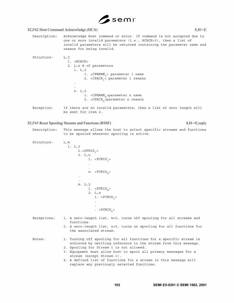
SEMI E5-0301 © SEMI 1982, 2001103
S2,F42 Host Command Acknowledge (HCA) S,H<-E
Description: Acknowledge Host command or error. If command is not accepted due toone or more invalid parameters (i.e., HCACK=3), then a list ofinvalid parameters will be returned containing the parameter name andreason for being invalid.
Structure: L,21. <HCACK>2. L,n # of parameters
1. L,21. <CPNAME1> parameter 1 name2. <CPACK1> parameter 1 reason
.
.n. L,2
1. <CPNAMEn>parameter n name2. <CPACKn>parameter n reason
Exception: If there are no invalid parameters, then a list of zero length willbe sent for item 2.
S2,F43 Reset Spooling Streams and Functions (RSSF) S,H->E,reply
Description: This message allows the host to select specific streams and functionsto be spooled whenever spooling is active.
Structure: L,m1. L,2
1.<STRID1>2. L,n
1. <FCNID1>..n. <FCNIDn>
.
.m. L,2
1. <STRIDm>2. L,n
1. <FCNID1>... <FCNIDn>
Exceptions: 1. A zero-length list, m=0, turns off spooling for all streams andfunctions.
2. A zero-length list, n=0, turns on spooling for all functions forthe associated stream.
Notes: 1. Turning off spooling for all functions for a specific stream isachieved by omitting reference to the stream from this message.
2. Spooling for Stream 1 is not allowed.3. Equipment must allow host to spool all primary messages for a
stream (except Stream 1).4. A defined list of functions for a stream in this message will
replace any previously selected functions.

SEMI E5-0301 © SEMI 1982, 2001 104
S2,F44 Reset Spooling Acknowledge (RSA) M,H<-E
Description: Acknowledge or error
Structure: L,21. <RSPACK> (accept or reject)2. L,m (m = number of streams with errors)
1. L,31. <STRID1>2. <STRACK1> (error in stream)3. L,n (n = number of functions in error)
1. <FCNID1>..n. <FCNIDn>
.
.m. L,3
1. <STRIDm>2. <STRACKm> (error in stream)3. L,n (n = number of functions in error)
1. <FCNID1>..n. <FCNIDn>
Exceptions: 1. If RSPACK=0, a zero-length list, m=0, is given, indicating nostreams or functions in error.
2. A zero-length list, n=0, indicates no functions in error forspecified stream.

SEMI E5-0301 © SEMI 1982, 2001105
S2,F45 Define Variable Limit Attributes (DVLA) M,H->E,reply
Structure: L,21. <DATAID>2. L,m (m=# of variables in this definition)
1. L,21. <VID1>2. L,n (n=# of limits being defined/changed for VID1)
1. L,21. <LIMITID1>2. L,p (p={0,2})
1. <UPPERDB1>2. <LOWERDB1>..n. L,2
1. <LIMITIDn>2. L,p (p={0,2})
1. <UPPERDBn>2. <LOWERDBn>
.
.m.L,2
1. <VIDm>2. L,n (n=# of limits being defined/changed for VIDm)
1. L,21. <LIMITID1>2. L,p (p={0,2})
1. <UPPERDB1>2. <LOWERDB1>
.
.n. L,2
1. <LIMITIDn>2. L,p (p={0,2})
1. <UPPERDBn>2. <LOWERDBn>
Exceptions: 1. A zero-length list, m=0, sets all limit values for all monitoredVIDs to "undefined.”
2. A zero-length list, n=0, sets all limits values for that VID to"undefined.”
3. A zero-length list, p=0, sets that limit to "undefined."

SEMI E5-0301 © SEMI 1982, 2001 106
S2,F46 Variable Limit Attribute Acknowledge (VLAA) M,H<-E
Description: Acknowledge definition of variable limit attributes or report error.If DVLA is not accepted due to one or more invalid parameters(e.g., LIMITACK=3), then a list of invalid parameters is returnedcontaining the variable limit attribute and reason for rejection. Ifan error condition is detected, the entire message is rejected (i.e.,partial changes are not allowed).
Structure: L,21. <VLAACK>2. L,m (m=number of invalid parameters)
1. L,31. <VID1> (VID with error)2.<LVACKp> (reason)3.L,n {n=0,2}
1. <LIMITID1> (1st limit in error for VIDp)2. <LIMITACK1> (reason)
.
.m. L,3
1. <VIDm> (VID with error)2. <LVACKm> (reason)3. L,n {n=0,2}
1. <LIMITID1> (1st limit in error for VIDx)2. <LIMITACK1> (reason)
Exceptions: 1. A zero-length list, m=0 indicates no invalid variable limitattributes.
2. A zero-length list, n=0 indicates no invalid limit values for thatVID.
S2,F47 Variable Limit Attribute Request (VLAR) S,H->E,reply
Description: This message allows the host to query the equipment for currentvariable limit attribute definitions.
Structure: L,m (m=# of VIDs this request)1. <VID1>..m. <VIDm>
Exception: A zero-length list, m=0, requests a list of all VID values that canhave variable limit attributes.
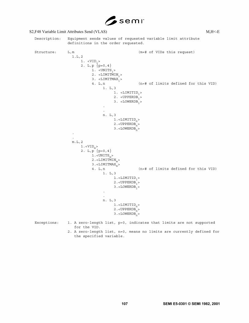
SEMI E5-0301 © SEMI 1982, 2001107
S2,F48 Variable Limit Attributes Send (VLAS) M,H<-E
Description: Equipment sends values of requested variable limit attributedefinitions in the order requested.
Structure: L,m (m=# of VIDs this request)1.L,2
1. <VID1>2. L,p {p=0,4}
1. <UNITS1>2. <LIMITMIN1>3. <LIMITMAX1>4. L,n (n=# of limits defined for this VID)
1. L,31. <LIMITID1>2. <UPPERDB1>3. <LOWERDB1>
.
.n. L,3
1.<LIMITIDn>2.<UPPERDBn>3.<LOWERDBn>
.
.m.L,2
1.<VIDm>2. L,p {p=0,4}
1.<UNITSm>2.<LIMITMINm>3.<LIMITMAXm>4. L,n (n=# of limits defined for this VID)
1. L,31.<LIMITID1>2.<UPPERDB1>3.<LOWERDB1>
.
.n. L,3
1.<LIMITIDn>2.<UPPERDBn>3.<LOWERDBn>
Exceptions: 1. A zero-length list, p=0, indicates that limits are not supportedfor the VID.
2. A zero-length list, n=0, means no limits are currently defined forthe specified variable.

SEMI E5-0301 © SEMI 1982, 2001 108
S2,F49 Enhanced Remote Command M,H->E
Description: The host requests an object to perform the specified remote commandwith its associated parameters. If multi-block, it shall be precededby the S2,F39/S2,F40 Multi-Block Inquire/Grant transaction.
Structure: L,41. <DATAID>2. <OBJSPEC>3. <RCMD>4. L,m # of parameter groups
1. L,21. <CPNAME1> command parameter 1 name2. <CEPVAL1> command-enhanced parameter 1 value
2. L,21. <CPNAME2> command parameter 2 name2. <CEPVAL2> command-enhanced parameter 2 value
.
.
.
.m. L,2
1. <CPNAMEm> command parameter m name2. <CEPVALm> command enhanced parameter m value
If a specific value of CPNAME is defined to have a CEPVAL defined asa LIST, it shall always be a LIST. If the CEPVAL that is associatedto that specific value of CPNAME is defined to be anything other thanLIST, it will result in a format error.
Exception: A zero length list, m = 0, indicates that no parameter groups aresent with the command. OBJSPEC can be a null length item.
Notes: 1. If CEPVAL is a LIST, the items that make up that list shall takeon one of the following forms: (1) a list of items with an identicalformat, (2) a LIST of CPNAME, CEPVAL pairs, as illustrated below.
A) L,2 B) L,21. <CPNAMEa> 1. <CPNAMEb>2. L,m 2. L,n
1. <CPVALa1> 1. L,22. <CPVALa2> 1. <CPNAMEb1>. 2. <CEPVALb1>. .. .. n. L,2. 1. <CPNAMEbn>. 2. <CEPVALbn>m. <CPVALam>

SEMI E5-0301 © SEMI 1982, 2001109
S2,F50 Enhanced Remote Command Acknowledge M,H<-E
Description: The equipment acknowledges Enhanced Remote Command or reports anyerror(s). If the command is not accepted due to one or more invalidparameters, (i.e. HCACK = 3), then a list of invalid parameters willbe returned containing the parameter name and reason for beinginvalid.
Structure: L,21. <HCACK>2. L,n # of parameter groups
1. L,21. <CPNAME1>2. <CEPACK1>
.
.n. L,2
1. <CPNAMEn>2. <CEPACKn>
7.7 Stream 3 Materials Status — T he functions of the material status stream are used to communicate informationand actions related to material, including carriers and material-in-process, time-to-completion information, andextraordinary material occurrences.
S3,F0 Abort Transaction (S3F0) S,H<->E
Description: Same form as S1,F0.
S3,F1 Material Status Request (MSR) S,H->E,reply
Description: Host requests the device to send the status of all material inprocess.
Structure: Header only
S3,F2 Material Status Data (MSD) M,H<-E
Description: Material-in-process information is sent from the equipment to thehost. There are m locations.
Structure: L,21. <MF>2. L,m
1. L,31. <LOC1>2. <QUA1>3. <MID1>
2. L,3..m. L,3
1. <LOCm>2. <QUAm>3. <MIDm>
Exception: A zero-length list returned means no such data exists.

SEMI E5-0301 © SEMI 1982, 2001 110
S3,F3 Time to Completion Request (TCR) S,H->E,reply
Description: Host requests the equipment to send the time-to-completion ofoperations on all material in possession.
Structure: Header only
S3,F4 Time to Completion Data (TCD) M,H<-E
Description: Time-to-completion information is sent by the equipment to the host.
Structure: L,21. <MF>2. L,m
1. L,31. <TTC1>2. <QUA1>3. <MID1>
2. L,3..m. L,3
1. <TTCm>2. <QUAm>3. <MIDm>
Exception: A zero-length list header returned means no such data exists.
S3,F5 Material Found Send (MFS) S,H<-E,[reply]
Description: The equipment advises the host that unsolicited material has appearedat one of its sensors.
Structure: L,21. <MF>2. <QUA>
S3,F6 Material Found Acknowledge (MFA) S,H->E
Description: Acknowledge or error
Structure: <ACKC3>
S3,F7 Material Lost Send (MLS) S,H<-E,[reply]
Description: The equipment advises the host that material has disappeared from itssensors.
Structure: L,31. <MF>2. <QUA>3. <MID>
S3,F8 Material Lost Acknowledge (MLA) S,H->E
Description: Acknowledge or error
Structure: <ACKC3>

SEMI E5-0301 © SEMI 1982, 2001111
S3,F9 Material ID Equate Send (IES) S,H<-E,reply
Description: Provide an alternative name to be used as equivalent to the originalmaterial ID.
Structure: L,21. <MID>2. <EMID>
S3,F10 Material ID Equate Acknowledge (IEA) S,H->E
Description: Acknowledge or error
Structure: <ACKC3>
S3,F11 Material ID Request (MIDR) S,H<-E,reply
Description: The equipment requests the Material ID of the material at thespecified port.
Structure: <PTN>
S3,F12 Material ID Request Acknowledge (MIRA) S,H->E
Description: The host acknowledges the request for the Material ID. If the use ofa request/acknowledge/send/acknowledge conversation is required, itindicated by the acknowledge code MIDRA=2. In this case, the send/acknowledge transaction is S3,F13, S3,Fl4. A timeout when electingS3,F13 is indicated by S9,F13 or a restart of the conversation, withS3,F11.
Structure: L,31. <PTN>2. <MIDRA>3. <MID>
Note: For all cases except MIDRA=0 (accepted, <MID> follows), the <MID>will be ignored by the receiver of message S3,F12. When MIDRA=0, azero-length MID indicates that no MID is available.
S3,F13 Material ID Send (MIS) S,H->E,reply
Description: The host sends the Material ID of the material at the specified port.
Structure: L,21. <PTN>2. <MID>
Note: A zero-length MID indicates that no MID is available.
S3,F14 Material ID Acknowledge (MIA) S,H<-E
Description: Acknowledge or error
Structure: <MIDAC>

SEMI E5-0301 © SEMI 1982, 2001 112
S3,F15 Materials Multi-Block Inquire (MMBI) S,H->E,reply
Description: This message requests permission to send a multi-block message basedupon a maximum length of the total message. It must be sent prior tosending any multi-block primary message in Stream 3.
Structure: L,21. <DATAID>2. <DATALENGTH>
S3,F16 Materials Multi-Block Grant (MMBG) S,H< - E
Description: This message grants or denies permission to send a multi-blockprimary message in Stream 3.
Structure: <GRANT>
S3,F17 Carrier Action Request M,H->E,reply
Description: This message requests an action to be performed for a specifiedcarrier. If multi-block, this message must be preceded by theS3,F11/F12 transaction.
Structure: L,51. <DATAID>2. <CARRIERACTION>3. <CARRIERSPEC>4. <PTN>5. L,n n = number of carrier attributes
1. L,21. <CATTRID1>2. <CATTRDATA1>
.
.n. L,2
1. <CATTRIDn>2. <CATTRDATAn>
Exception: If n = 0, then no carrier attributes are included. If CARRIERSPEC isnot a zero-length item, then PTN may be omitted (a zero-length item).
S3,F18 Carrier Action Acknowledge S,H<-E
Description: This message acknowledges the carrier action request.
Structure: L,21. <CAACK>2. L,n
1. L,21. <ERRCODE
1>
2. <ERRTEXT1>
.
.n. L,2
1. <ERRCODEn>
2. <ERRTEXTn>
Exception: If n = 0, no errors exist.

SEMI E5-0301 © SEMI 1982, 2001113
S3,F19 Cancel All Carrier Out Request S,H->E, reply
Description: This message is used to cancel all pending carrier out requests.
Structure: Header only.
S3,F20 Cancel All Carrier Out Acknowledge S,H<-E
Description: This message acknowledges the Cancel Carrier Out request.
Structure: L,21. <CAACK>2. L,n
1. L,21. <ERRCODE
1>
2. <ERRTEXT1>
.
.n. L,2
1. <ERRCODEn>
2. <ERRTEXTn>
Exception: If n = 0, no errors exist.
S3,F21 Port Group Definition S,H->E, reply
Description: This message defines the port in a port group and provides theinitial port access.
Structure: L,31. <PORTGRPNAME>2. <PORTACCESS>3. L,n
1. <PTN1>
.
.n. <PTN
n>
S3,F22 Port Group Definition Acknowledge S,H<-E
Description: This message acknowledges the port group definition.
Structure: L,21. <CAACK>2. L,n
1. L,21. <ERRCODE
1>
2. <ERRTEXT1>
.
.n. L,2
1. <ERRCODEn>
2. <ERRTEXTn>
Exception: If n = 0, no errors exist.

SEMI E5-0301 © SEMI 1982, 2001 114
S3,F23 Port Group Action Request S,H->E, reply
Description: This message requests an action be performed for a port group. Theaccess mode may be changed or the port group may be deleted.
Structure: L,31. <PGRPACTION>2. <PORTGRPNAME>3. L,m
1. L,21. <PARAMNAME
1>
2. <PARAMVAL1>
.
.m. L,2
3. <PARAMNAME1>
4. <PARAMVAL1>
Exception: If m = 0, then no parameters are provided.
S3,F24 Port Group Action Acknowledge S,H<-E
Description: This message acknowledges the port group action.
Structure: L,21. <CAACK>2. L,n
1. L,21. <ERRCODE
1>
2. <ERRTEXT1>
.
.n. L,2
1. <ERRCODEn>
2. <ERRTEXTn>
Exception: If n = 0, no errors exist.
S3,F25 Port Action Request S,H->E, reply
Description: This message requests an action be performed for a port.
Structure: L,21. <PORTACTION>2. <PTN>4. L,m
2. L,25. <PARAMNAME
1>
6. <PARAMVAL1>
.
.m. L,2
7. <PARAMNAME1>
8. <PARAMVAL1>
Exception: If m = 0, then no parameters are provided.

SEMI E5-0301 © SEMI 1982, 2001115
S3,F26 Port Action Acknowledge S,H<-E
Description: This message acknowledges the port action request.
Structure: L,21. <CAACK>2. L,n
1. L,23. <ERRCODE
1>
4. <ERRTEXT1>
.
.n. L,2
1. <ERRCODEn>
2. <ERRTEXTn>
Exception: If n = 0, no errors exist.
7.8 Stream 4 Material Control — The material control stream contains the original material control protocol andthe newer protocol which supports SEMI E32.
7.8.1 Original Material Control Pro tocol — The functions in the material control stream are used to effect theautomatic transfer of material between equipment. A simple handshake is achieved which provides for a variety oferror conditions which gracefully terminate the handshake. Separate messages advise the host of errors andcompleted material transfers.
7.8.1.1 Since the handshake and host messages are separate, the handshake may be achieved transparently throughthe host or by direct connection between equipment. The host completes the handshake by relaying messagesbetween the equipment. Only a single port is required on the equipment, and the equipment has a simple messagehandling requirement. When a direct connection is desired, at least three ports are required, the receiving equipmentmust look like the host with respect to the sending equipment, and message handling in the equipment issignificantly more complicated than in the host-only connection. Nevertheless, the direct connection may still bechosen in an attempt to provide operation without a host. Since the host is reasonably transparent in the materialhandshake, a simple explanation of the handshake may be achieved by just considering the exchange of messagesbetween the sender, the equipment wanting to get rid of material, and the receiver (the equipment able to accept thematerial).
7.8.1.2 Figure S4.1 shows six possible handshake situations between the sender and the receiver. There are twonormal handshakes. Figure S4.1(a) shows the normal three-message exchange when material is passed betweenequipment. The host is informed of a complete transfer of material. Figure S4.1(b) shows an alternative messageexchange where the sender changes its mind and decides not to send the material. Figures S4.1(c) and (d) show twosituations where the material gets stuck during the transfer. In each situation an error message is issued to the hostfrom the equipment where the material is stuck. The other equipment terminates normally. When material is stuck,manual intervention is required to move the material towards the equipment which indicates the stuck condition. Themanual intervention has two possible outcomes. One, the material can be moved to a position where the handshakecan resume or, two, the material is broken or lost from the transfer. Lost material causes a lost material errormessage to be sent to the host prior to resuming the operation. The specific details of recovering front stuck materialare equipment-dependent. The stuck material condition is determined by the amount of time the material transfermechanism is turned on. The sender claims stuck material if the material is not clear of its sensor before a time t1.The receiver claims stuck material if the material is not received before time t2. Figures S4.1(e) and (f) show thepossible error conditions in the unlikely event that for some reason a handshake message is lost. Figure S4.1(e)shows that time t3 is the longest that the sender will wait for material received message. Times t2 and t3 set an upperlimit on the amount of time either material transport mechanism will operate.
7.8.1.3 Figure S4.2 summarizes the in teraction of the timers, handshake messages, and the error messages in theform of a flow chart. It also identifies specific states for the sender and the receiver. These states are referred to inthe messages.The ranges of timer values are as follows:

SEMI E5-0301 © SEMI 1982, 2001 116
tl — time to leave sender
tl+10<= t2<= 60sec.---time to receive
t2+10<= t3<= 70sec.---time to complete send
Default values, tl= 10 sec., t2= 60 sec., t3= 70 sec.
NOTE 7: t1, t2, t3 defined for Stream 4 are not to be confused with timeouts T1, T2, T3, and T4 defined in SEMI E4 (SECS-I).
Figure S4.1The Six Possible Handshakes

SEMI E5-0301 © SEMI 1982, 2001117
Figure S4.2Material Control-Handshake Flowchart

SEMI E5-0301 © SEMI 1982, 2001 118
S4,F0 Abort Transaction (S4F0) S,H->E
Description: Same form as S1,F0.
S4,F1 Ready to Send Materials (RSN) S,H<->E,reply
Description: The sender advises the receiver that some material is awaitingtransfer.
Structure: L,21. <PTN>2. <MID>
S4,F2 Ready to Send Acknowledge (RSA) S,H<->E
Description: Acknowledge or error
Structure: <RSACK>
S4,F3 Send Material (SMN) S,H<->E
Description: The receiver advises the sender that it is ready to receive materialand that its transfer mechanism is running.
Structure: L,21. <PTN>2. <MID>
S4,F4 Not Used
S4,F5 Handshake Complete (HCN) S,H<->E
Description: Receiver advises sender that the handshake is complete. The sendermay now stop its transfer mechanism.
Structure: L,21. <PTN>2. <MID>
S4,F6 Not Used
S4,F7 Not Ready to Send (ABN) S,H<->E
Description: Sender advises receiver that no material is being sent. The receivermay now stop its transfer mechanism.
Structure: L,21. <PTN>2. <MID>
S4,F8 Not Used

SEMI E5-0301 © SEMI 1982, 2001119
S4,F9 Stuck in Sender (SSN) S,H<-E
Description: An error from the sender to the host. The time between the receipt ofMaterial (SMN) and the material leaving the sender's sensor exceedsthe sender's t1 timeout. The sender goes to a hold state until thedisposition of the stuck material is determined.
Structure: L,21. <PTN>2. <MID>
S4,F10 Not Used
S4,F11 Stuck in Receiver (SRN) S,H<-E
Description: An error from the receiver to the host. The time between SendMaterial (SMN) and detection of the material at the receiver exceedsthe receiver's t2 timeout. The receiver goes to a hold state untilthe disposition of material is determined.
Structure: L,21. <PTN>2. <MID>
S4,F12 Not Used
S4,F13 Send Incomplete Timeout (SIN) S,H<-E
Description: An error from the sender to the host. The time between the receipt ofthe Send Material (SMN) and the receipt of Handshake-Complete (HCN)exceeds the sender's t3 timeout. There has been an error in thehandshake and the transfer mechanism is turned off.
Structure: L,21. <PTN>2. <MID>
S4,F14 Not Used
S4,F15 Material Received (MRN) S,H<-E
Description: A message from the receiver to the host. Material has beentransferred to the receiver.
Structure: L,21. <PTN>2. <MID>
S4,F16 Not Used

SEMI E5-0301 © SEMI 1982, 2001 120
S4,F17 Request to Receive (RTR) S,H<->E,reply
Description: Receiver requests the sender initiate a conversation to send thespecified material to the specified port.
Structure: L,21. <PTN>2. <MID>
Exceptions: A zero-length MID means equipment doesn't know MID.
S4,F18 Request to Receive Acknowledge (RRA) S,H<->E
Description: Acknowledge or error
Structure: <RRACK>
7.8.2 Support for Material Movement Management Services — The following messages were defined to supportSEMI E32.
7.8.2.1 Macro Level Messages — The following messages support the host supervised macro level of materialmovement as defined in SEMI E32. Stream 1 Macro Level Messages can be found in Section 7.5: S1F19, GetAttribute (GA); S1F20, Attribute Data (AD).

SEMI E5-0301 © SEMI 1982, 2001121
S4,F19 Transfer Job Create (TJ) M,H—>E,reply
Description: The host requests that the equipment undertake one or more discrete(or atomic) transfers to achieve a host defined objective. The hostprovides the transfer specifications for each atomic transfer. Atomictransfers on separate ports on the equipment are allowed to executein parallel. Atomic transfers for a port must be executedsequentially or in some cases concurrently. Both equipment transferpartners for each atomic transfer must receive appropriate TransferJob Request messages in order to execute a transfer. If S4,F20 ismulti-block, it must be preceded by the S4,F25/S4,F26 Inquire/Granttransaction.
Structure: L,21.<DATAID>2.L,2
1.<TRJOBNAME>2.L,n [n=#atomic xfrs defined for this job]
1.L,12 [Specification for first atomic xfr]1.<TRLINK> [Atomic transfer identifier]2.<TRPORT> [Port to be used for transfer]3.<TROBJNAME> [Transfer object identifier]4.<TROBJTYPE> [Object type–what form is the material
in]5.<TRROLE> [Role in transfer–primary/secondary]6.<TRRCP> [Transfer recipe identifier]7.<TRPTNR> [Identifier of transfer partner]8.<TRPTPORT> [Partner's Port to be Used]9.<TRDIR> [Transfer direction-send or receive]10.<TRTYPE> [Active or Passive]11.<TRLOCATION> [Location to send/receive mtl]12.<TRAUTOSTART> [Does eqp await host start command
after setup?]..n.L,12 [Specification for nth atomic xfr]
1.<TRLINK]↓12.<TRAUTOSTART>

SEMI E5-0301 © SEMI 1982, 2001 122
S4,F20 Transfer Job Acknowledge (TJA) S,H<—E
Description: The equipment informs the host of its acceptance or rejection of theTransfer Job Request.
Structure: L,31.<TRJOBID>2. L,m [m=number of atomic transfers in the transfer job.]
1.<TRATOMICID1>..m.<TRATOMICIDm>
3. L,21.<TRACK> [Accepted or rejected]2. L,n [n=# errors reported]
1. L,21.<ERRCODE1>2.<ERRTEXT1>
.
.n. L,2
1.<ERRCODEn>2.<ERRTEXTn>
Exception: A zero-length list (m=0) is sent if the transfer job is rejected.A zero-length list (n=0) is sent if the transfer job is accepted.
S4,F21 Transfer Job Command (TC) S,H—>E,reply
Description: This message is used by the host to modify a current transfer job onan equipment.
Structure: L,31.<TRJOBID>2.<TRCMDNAME> [identifier of the transfer command]3.L,n [n=number of parameters=0 if none]
1.L,21.<CPNAME1> [transfer parameter name]2.<CPVAL1> [transfer parameter value]
.
.n. L,2
1.<CPNAMEn>2.<CPVALn>

SEMI E5-0301 © SEMI 1982, 2001123
S4,F22 Transfer Command Acknowledge (TCA) S,H<—E
Description: Equipment accepts or rejects the transfer command.
Structure: L,21.<TRACK> [Accepted or rejected]2. L,n [n=# errors reported]
1. L,21.<ERRCODE1>2.<ERRTEXT1>
.
.n. L,2
1.<ERRCODEn>2.<ERRTEXTn>
Exception: If the command is accepted, n=0.
S4,F23 Transfer Job Alert (TJA) S,H<—E,[reply]
Description: Equipment informs the host that a transfer job milestone has beenreached (e.g., job started or job complete). If complete, allequipment resources originally reserved for the transfer have beenreleased.
Structure: L,41.<TRJOBID>2.<TRJOBNAME>3.<TRJOBMS>4. L,2
1.<TRACK> [success or failure]2. L,n [n=# errors reported]
1. L,21.<ERRCODE1>2.<ERRTEXT1>
.
.n. L,2
1.<ERRCODEn>2.<ERRTEXTn>
Exception: If the transfer job is completed successfully, n=0.
S4,F24 Transfer Alert Acknowledge (TLA) S,H—>E
Description: Acknowledge receipt of the S4,F23 message.
Structure: Header Only
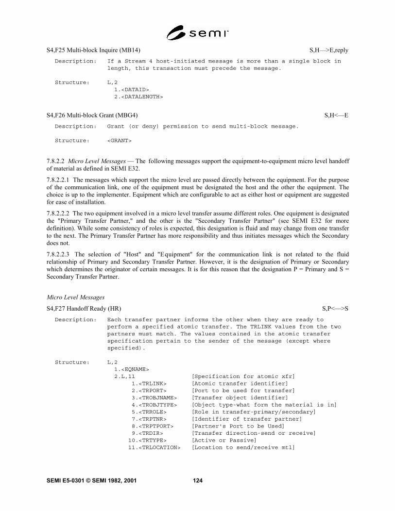
SEMI E5-0301 © SEMI 1982, 2001 124
S4,F25 Multi-block Inquire (MB14) S,H—>E,reply
Description: If a Stream 4 host-initiated message is more than a single block inlength, this transaction must precede the message.
Structure: L,21.<DATAID>2.<DATALENGTH>
S4,F26 Multi-block Grant (MBG4) S,H<—E
Description: Grant (or deny) permission to send multi-block message.
Structure: <GRANT>
7.8.2.2 Micro Level Messages — The following messages support the equipment-to-equipment micro level handoffof material as defined in SEMI E32.
7.8.2.2.1 The messages which support the micro level are passed directly between the equipment. For the purposeof the communication link, one of the equipment must be designated the host and the other the equipment. Thechoice is up to the implementer. Equipment which are configurable to act as either host or equipment are suggestedfor ease of installation.
7.8.2.2.2 The two equipment involved in a micro level transfer assume different roles. One equipment is designatedthe "Primary Transfer Partner," and the other is the "Secondary Transfer Partner" (see SEMI E32 for moredefinition). While some consistency of roles is expected, this designation is fluid and may change from one transferto the next. The Primary Transfer Partner has more responsibility and thus initiates messages which the Secondarydoes not.
7.8.2.2.3 The selection of "Host" and "Equipment" for the communication link is not related to the fluidrelationship of Primary and Secondary Transfer Partner. However, it is the designation of Primary or Secondarywhich determines the originator of certain messages. It is for this reason that the designation P = Primary and S =Secondary Transfer Partner.
Micro Level Messages
S4,F27 Handoff Ready (HR) S,P<—>S
Description: Each transfer partner informs the other when they are ready toperform a specified atomic transfer. The TRLINK values from the twopartners must match. The values contained in the atomic transferspecification pertain to the sender of the message (except wherespecified).
Structure: L,21.<EQNAME>2.L,11 [Specification for atomic xfr]
1.<TRLINK> [Atomic transfer identifier]2.<TRPORT> [Port to be used for transfer]3.<TROBJNAME> [Transfer object identifier]4.<TROBJTYPE> [Object type-what form the material is in]5.<TRROLE> [Role in transfer-primary/secondary]7.<TRPTNR> [Identifier of transfer partner]8.<TRPTPORT> [Partner's Port to be Used]9.<TRDIR> [Transfer direction-send or receive]10.<TRTYPE> [Active or Passive]11.<TRLOCATION> [Location to send/receive mtl]

SEMI E5-0301 © SEMI 1982, 2001125
S4,F28 Not Used
S4,F29 Handoff Command (HC) S,P—>S
Description: Command issued by the primary to the secondary transfer partner toachieve some physical action.
Structure: L,41.<TRLINK> [Atomic Transfer identifier]2.<MCINDEX> [Identified this specific Micro Cmd request]3.<HOCMDNAME> [Requested Micro Cmd]4.L,n [n=number of parameters]
1.L,21.<CPNAME1> [Micro Cmd parameter name]2.<CPVAL1> [Micro Cmd parameter value]
.
.n.L,2
1.<CPNAMEn>2.<CPVALn>
Exception: n=0 if no parameters are used.
S4,F30 Not Used
S4,F31 Handoff Command Complete (HCC) S,P<—S
Description: Completion status of the micro command. This is sent from thesecondary to the primary transfer partner when the command iscompleted or terminated.
Structure: L,31.<TRLINK> [Atomic Transfer identifier]2.<MCINDEX> [Links to specific micro command (S4,F31)]3.L,2
1.<HOACK> [success or failure]2.L,n [n=# errors reported]
1.L,21.<ERRCODE1>2.<ERRTEXT1>
.
.n.L,2
1.<ERRCODEn>2.<ERRTEXTn>
S4,F32 Not Used

SEMI E5-0301 © SEMI 1982, 2001 126
S4,F33 Handoff Verified (HV) P<—>S
Description: Sent by the primary transfer partner to inform the secondary that nomore micro commands will be issued for this atomic transfer and torequest a verification that the transfer is complete and successful.Also sent by the secondary partner following the receipt of thismessage to verify that the transfer is complete and successful (or toreport problems).
Structure: L,21.<TRLINK>2.L,2
1.<HOACK> [success or failure]2.L,n [n=# errors reported]
1.L,21.<ERRCODE1>2.<ERRTEXT1>
.
.n.L,2
1.<ERRCODEn>2.<ERRTEXTn>
S4,F34 Not Used
S4,F35 Handoff Cancel Ready (HCR) P<—>S
Description: Sent by either transfer partner to cancel a previous Handoff Readymessage. This message is valid only before the handoff has begun.
Structure: <TRLINK>
S4,F36 Not Used
S4,F37 Handoff Cancel Ready Acknowledge (HCA) P<—>S
Description: Sent by the receiver of the Handoff Cancel Ready message to accept ordeny the cancel. The cancel request is denied if the handoff processhas begun.
Structure: L,21.<TRLINK>2.<HOCANCELACK>
S4,F38 Not Used
S4,F39 Handoff Halt (HH) P<—>S
Description: Sent by either transfer partner to cause all transfer relatedactivity of the other to cease immediately. It is used when theequipment or material is at risk of damage.
Structure: <TRLINK>

SEMI E5-0301 © SEMI 1982, 2001127
S4,F40 Not Used
S4,F41 Handoff Halt Acknowledge (HHA) P<—>S
Description: Sent to equipment's transfer partner following completion of haltactivities resulting from a previously received S4,F39.
Structure: L,21.<TRLINK>2.<HOHALTACK>
S4,F42 Not Used
7.9 Stream 5 Exception Handling — This stream contains messages regarding binary and analog equipmentexceptions. Exceptions are classified into two categories: errors and alarms. Messages S5,F1 through S5,F8 of thissection provide basic alarm messages. The messages S5,F9 through S5,F18 provide extended capabilities forException Handling. When using messages F1 - F8, alarms may be divided into categories as follows:1. personal safety — Condition may be dangerous to people.
2. equipment safety — Condition may harm equipment.
3. parameter control warning — Parameter variation outside of preset limits — may harm product.
4. parameter control error — Parameter variation outside of reasonable control limits — may indicate anequipment malfunction.
5. irrecoverable error — Intervention required before normal use of equipment can resume.
6. equipment status warning — An unexpected condition has occurred, but operation can continue.
7. attention flags — A signal from a process program indicating that a particular step has been reached.
8. data integrity — A condition which may cause loss of data; usually related to Stream 6.
7.9.1 For messages F1 through F8, i t will be the equipment's responsibility to categorize the alarm. Some alarmconditions may cause more than one type of alarm to be issued. For example, a parameter control error on overtemperature may also trip a protective device that makes the alarm irrecoverable without some intervention.
S5,F0 Abort Transaction (S5F0) S,H<->E
Description: Same form as S1,F0.
S5,F1 Alarm Report Send (ARS) S,H<-E,[reply]
Description: This message reports a change in or presence of an alarm condition.One message will be issued when the alarm is set and one message willbe issued when the alarm is cleared. Irrecoverable errors andattention flags may not have a corresponding clear message.
Structure: L,31. <ALCD>2. <ALID>3. <ALTX>

SEMI E5-0301 © SEMI 1982, 2001 128
S5,F2 Alarm Report Acknowledge (ARA) S,H->E
Description: Acknowledge or error
Structure: <ACKC5>
S5,F3 Enable/Disable Alarm Send (EAS) S,H->E,[reply]
Description: This message will change the state of the enable bit in theequipment. The enable bit determines if the alarm will be sent to thehost. Alarms which are not controllable in this way are unaffected bythis message.
Structure: L,21. <ALED>2. <ALID>
Exception: A zero-length item for ALID means all alarms.
S5,F4 Enable/Disable Alarm Acknowledge (EAA) S,H<-E
Description: Acknowledge or error
Structure: <ACKC5>
S5,F5 List Alarms Request (LAR) S,H->E,reply
Description: This message requests the equipment to send binary and analog alarminformation to the host.
Structure: <ALID1, . . . ,ALIDn>
Exception: A zero-length item means send all possible alarms regardless of thestate of ALED.
S5,F6 List Alarm Data (LAD) M,H<-E
Description: This message contains the alarm data known to the equipment. Thereare “m” alarms in the list.
Structure: L,m1. L,3
1. <ALCD1>2. <ALID1>3. <ALTX1>
2. L,3..m. L,3
1. <ALCDm>2. <ALIDm>3. <ALTXm>
Exception: If m=0, no response can be made. A zero-length item returned forALCDi or ALTXi means that value does not exist.

SEMI E5-0301 © SEMI 1982, 2001129
S5,F7 List Enabled Alarm Request (LEAR) S,H->E,reply
Description: List alarms which are enabled.
Structure: Header only
S5,F8 List Enabled Alarm Data (LEAD) M,H<-E
Description: This message is similar to S5,F6 except that it lists only alarmswhich are enabled.
Structure: Same as S5,F6
S5,F9 Exception Post Notify (EXPN) S,H<-E,[reply]
Description: This message provides the means to inform a host system that anexception condition is 'set'. Optionally, recovery actions for theexception may be sent.
Structure: L,51. <TIMESTAMP>2. <EXID>3. <EXTYPE>4. <EXMESSAGE>5. L,n
1. <EXRECVRA1>...n. <EXRECVRAn>
Exception: A zero-length list (n = 0) shall be sent when there are no possiblerecovery actions.
Exception: This is a single block message. The text in each of the EXRECVRAdata items may need to be restricted in length to meet the singleblock requirement.
S5,F10 Exception Post Confirm (EXPC) S,H->E
Description: Host confirms receipt of S5,F9 message from the equipment.
Structure: Header only
S5,F11 Exception Clear Notify (EXCN) S,H <-E,[reply]
Description: This message provides the means to inform a host system that anexception/alarm condition is no longer active (set).
Structure: L,41. <TIMESTAMP>2. <EXID>3. <EXTYPE>4. <EXMESSAGE>
Exception: EXMESSAGE can be used to provide the reason that the exceptioncleared.

SEMI E5-0301 © SEMI 1982, 2001 130
S5,F12 Exception Clear Confirm (EXCC) S,H->E
Description: Host confirms receipt of S5,F11 message from the equipment.
Structure: Header only
S5,F13 Exception Recover Request (EXRR) S,H->E,reply
Description: Request that the entity which is experiencing an error execute arecovery action.
Structure: L,21. <EXID>2. <EXRECVRA>
S5,F14 Exception Recover Acknowledge (EXRA) S,H<-E
Description: The entity indicates a response to the recovery request.
Structure: L,21. <EXID>2. L,2
1. <ACKA>2. L,m (m = {0,2})
1. <ERRCODE>2. <ERRTEXT>
Exception: The list m can be zero length, if the recovery request was accepted.
S5,F15 Exception Recovery Complete Notify (EXRCN) S,H<-E,[reply]
Description: Allows the service provider to inform the controller/host that therecovery operation completed on a specific exception and an errorcode if the recovery terminated abnormally.
Structure: L,31. <TIMESTAMP>2. <EXID>3. L,2
1. <ACKA>2. L,m (m = {0,2})
1. <ERRCODE>2. <ERRTEXT>
Exception: This list m can be of zero length if the recovery was successful.
S5,F16 Exception Recovery Complete Confirm (EXRCC) S,H->E
Description: Host confirms receipt of S5,F15 message from the equipment.
Structure: Header only
S5,F17 Exception Recovery Abort Request (EXRAR) S,H->E,reply
Description: Stop the recovery procedure on a specific exception.
Structure: 1. <EXID>

SEMI E5-0301 © SEMI 1982, 2001131
S5,F18 Exception Recovery Abort Acknowledge (EXRAA) S,H<-E
Description: Indicate the success of the request for Recovery Abort.
Structure: L,21. <EXID>2. L,2
1. <ACKA>2. L,m (m = {0,2})
1. <ERRCODE>2. <ERRTEXT>
Exception: The list m can be of zero length if the abort was successful.
7.10 Stream 6 Data Collection — This stream is intended to cover the needs of in-process measurements andequipment monitoring.
S6,F0 Abort Transaction (S6F0) S,H<->E
Description: Same form as S1,F0.
S6,F1 Trace Data Send (TDS) M,H<-E,[reply]
Description: This function sends samples to the host according to the trace setupdone by S2,F23. Trace is a time-driven form of equipment status.
Even if S6,F1 is multi-block, it is not preceded by an Inquire/Granttransaction, because the Host S2,F23 is an implicit grant. Someequipment may support only single-block S6,F1, and may refuse anS2,F23 (Trace Initiate Send) message which would cause a multi-blockS6,F1.
Structure: L,41. <TRID>2. <SMPLN>3. <STIME>4. L,n
1. <SV1>2. <SV2>..n. <SVn>
Exception: A zero-length STIME means no value is given and that the time is tobe derived from SMPLN along with knowledge of the request.
S6,F2 Trace Data Acknowledge (TDA) S,H->E
Description: Acknowledge or error
Structure: <ACKC6>

SEMI E5-0301 © SEMI 1982, 2001 132
S6,F3 Discrete Variable Data Send (DVS) M,H<-E,[reply]
Description: Any data report which is initiated by an event, such as thecompletion of a measurement, rather than passage of time is called adiscrete variable. Some equipment may have several possible events onwhich to send the data. S2,F15 is used to select the desiredreporting events. Reports requiring only one block of data may reportdirectly to the host with this message. If S6,F3 is multi-block, itmust be preceded by the S6,F5/S6,F6 Inquire/Grant transaction.
Structure: L,31.<DATAID>2.<CEID>3. L,n
1. L,21. <DSID1>2. L,m
1. L,21. <DVNAME1>2. <DVVAL1>
2. L,2..m. L,2
1. <DVNAMEm>2. <DVVALm>
2. L,2..n. L,2
1. <DSIDn>2. etc.
S6,F4 Discrete Variable Data Acknowledge (DVA) S,H->E
Description: Acknowledge or error
Structure: <ACKC6>
S6,F5 Multi-block Data Send Inquire (MBI) S,H<-E,reply
Description: If the discrete data report S6F3, F9, F11, F13 can involve more thanone block, this transaction must precede the transmission.
Structure: L,21. <DATAID>2. <DATALENGTH>
S6,F6 Multi-block Grant (MBG) S,H->E
Description: Grant permission to send
Structure: <GRANT6>

SEMI E5-0301 © SEMI 1982, 2001133
S6,F7 Data Transfer Request (DDR) S,H->E,reply
Description: The host may initiate a data transfer of specified data stored in theequipment with this function.
Structure: <DATAID>
S6,F8 Data Transfer Data (DDD) M,H<-E
Description: Equipment sends data to the host.
Structure: Similar to the structure of S6,F3
Exception: A zero-length item returned means the requested data cannot be sent.
S6,F9 Formatted Variable Send (FVS) M,H<-E,[reply]
Description: The same function as S6,F3 except that the DVNAMEs are supplied froma predefined form that is known to the host. Thus, the data are morecompact. If S6,F9 is multi-block, it must be preceded by theS6,F5/S6, F6 Inquire/Grant transaction.
Structure: L,41.<PFCD>2.<DATAID>3.<CEID>4. L,n
1. L,21. <DSID11>2. L,m
1. <DVVAL1>..m. <DVVALm>
2. L,2..n. L,2
1. <DSIDn>2. etc.
S6,F10 Formatted Variable Acknowledge (FVA) S,H->E
Description: Acknowledge or error
Structure: <ACKC6>

SEMI E5-0301 © SEMI 1982, 2001 134
S6,F11 Event Report Send (ERS) M,H<-E, reply
Description: The purpose of this message is for the equipment to send a defined,linked, and enabled group of reports to the host upon the occurrenceof an event (CEID).
If S6,F11 is Multi-block, it must be preceded by the S6,F5/S6,F6Inquire/Grant transaction.
Structure: L,31.<DATAID>2.<CEID>3.L,a
1. L,21. <RPTID1>2. L,b
1.<V1>..b.<Vb>
.
.a.L,2 report a
1. <RPTIDa>2. L,c#Vs this report
1. <V1>..c.<Vc>
Exceptions: If there are no reports linked to the event a 'null' report isassumed. A zero-length list for # of reports means there are noreports linked to the given CEID.
S6,F12 Event Report Acknowledge (ERA) S,H->E
Description: Acknowledge or error
Structure: <ACKC6>

SEMI E5-0301 © SEMI 1982, 2001135
S6,F13 Annotated Event Report Send (AERS) M,H<-E,reply
Description: This message is the same as S6F11 with the exception that VID's aresent with data.
If S6,F13 is Multi-block, it must be preceded by the S6,F5/S6,F6Inquire/Grant transaction.
Structure: L,31.<DATAID>2.<CEID>3. L,a
1. L,21. <RPTID1>2. L,b
1. L,21.<VID1>
.
.b. L,2
1.<VIDb>b.<Vb>
.
.a. L,2
1. <RPTIDa>2. L,c
1. L,21.<VID1>2.<V1>..c. L,2
1.<VIDc>2.<Vc>
Exception: If there are no reports linked to the event a 'null' report isassumed. A zero-length list for # of reports means there are noreports linked to the given CEID.
S6,F14 Annotated Event Report Acknowledge (AERA) S,H->E
Description: Acknowledge or error
Structure: <ACKC6>
S6,F15 Event Report Request (ERR) S,H->E, reply
Description: The purpose of this message is for the host to demand a given reportgroup from the equipment.
Structure: <CEID>

SEMI E5-0301 © SEMI 1982, 2001 136
S6,F16 Event Report Data (ERD) M,H<-E
Description: Equipment sends reports linked to given CEID to host.
Structure: Identical to structure of S6,F11.
Exceptions: A zero-length item means there are no reports linked to the givenCEID.
S6,F17 Annotated Event Report Request (AERR) S,H->E,reply
Description: Same as S6,F15, but requests annotated reports.
Structure: <CEID>
S6,F18 Annotated Event Report Data (AERD) M,H<-E
Description: Equipment sends annotated reports linked to given CEID.
Structure: Same as S6,F13.
Exceptions: A zero-length item means there are no reports linked to the givenCEID.
S6,F19 Individual Report Request (IRR) S,H->E,reply
Description: The purpose of this message is for the host to request a definedreport from the equipment.
Structure: <RPTID>
S6,F20 Individual Report Data (IRD) M,H<-E
Description: Equipment sends variable data defined for the given RPTID to thehost.
Structure: L,n # of variable data items1. <V1>..n. <Vn>
Exceptions: A zero length list means RPTID is not defined.
S6,F21 Annotated Individual Report Request (AIRR) S,H->E,reply
Description: The purpose of this message is for the host to request an annotateddefined report from the equipment.
Structure: <RPTID>

SEMI E5-0301 © SEMI 1982, 2001137
S6,F22 Annotated Individual Report Data (AIRD) M,H<-E
Description: Equipment sends annotated variable data defined for the given RPTIDto the host.
Structure: L,n # of variable data items1.L,2
1. <VID1>2. <V1>
.
.n. L,2
1. <VIDn>2. <Vn>
Exceptions: A zero-length list for # of variable data items means RPTID is notdefined.
S6,F23 Request Spooled Data (RSD) S,H->E,reply
Description: The purpose of this message is for the host to request transmissionor deletion of the messages currently spooled by the equipment.
Structure: <RSDC>
S6,F24 Request Spooled Data Acknowledgement Send (RSDAS) S,H<-E
Description: The purpose of this message is to acknowledge the receipt of theRequest Spooled Data (S6,F23) and to respond with an appropriateacknowledge code.
Structure: <RSDA>

SEMI E5-0301 © SEMI 1982, 2001 138
S6,F25 Notification Report Send M, H<->E,[reply]
Description: This message is used for change notifications or confirmationreports. A change notification is a report of an internal action andis not associated with a prior action requested by the host.
A confirmation report is always associated with an earlier request for action. Aconfirmation report is sent to the initial requestor of a delayed action at the timethe action is completed. A delayed action is an action that is any action notperformed before the response to the initial request is sent. OPID contains thevalue of OPID in the initial request. LINKID is set to a non-zero value if and onlyif additional completion reports with the same OPID will be sent. If S6,F25 ismultiblock, it must be preceded by the S6,F5/S6,F6 Inquire Grant transaction.
Structure: L,71. <DATAID>2. <OPID>3. <LINKID>4. <RCPSPEC>5. <RMCHGSTAT>6. L,m
1. L,21. <RCPATTRID1>2. <RCPATTRDATA1>
.
.m. L,2
1. <RCPATTRIDm>2. <RCPATTRDATAm>
7. L,21. <RMACK>2. L,p
1. L,21. <ERRCODE1>2. <ERRTEXT1>
.
.p. L,2
1. <ERRCODEp>2. <ERRTEXTp>
Exception: OPID and LINKID are zero-length items when and only when S6,F25 issent as a change notification rather than as a confirmation report.p = 0 if and only if RMACK indicates no errors.
S6,F26 Notification Report Send Acknowledge S, H<->E
Description: This message is used to acknowledge the confirmation report. It isdefined for completeness and as an aid to the user in identifyingproblems.
Structure: <ACKC6>
Exception: None

SEMI E5-0301 © SEMI 1982, 2001139
S6,F27 Trace Report Send (TRS) M,H <-E,[reply]
Description: The equipment sends a completed Trace Report to the host.
Structure: L,31. <DATAID>2. <TRID>3. L,n (n cannot exceed group size specified by S2F53)
1. L,p (p is the number of reports for each trace sample)1. L,2
1. <RPTID1>2. L,m (number of items in this data report)
1. <V1>..m. <Vm>
.
.p. L,2
1. <RPTIDp>2. L,m
1. <V1>..m. <Vm>
.
.n. L,p (p is the number of reports for each trace sample)
1. L,21. <RPTID1>2. L,m (number of items in this data report)
1. <V1>..m. <Vm>
.
.p. L,2
1. <RPTIDp>2. L,m
1. <V1>..m. <Vm>
Exception: The lists of variables associated with a unique RPTID are alsounique. This structure illustrates the form of the message, so ingeneral, V1 for RPTIDa and V1 for RPTIDb do not reference the samevariable.
S6,F28 Trace Report Send Acknowledge S,H ->E
Description: The host Acknowledges receipt of the Trace Report.
Structure: <TRID>

SEMI E5-0301 © SEMI 1982, 2001 140
S6,F29 Trace Report Request (TRR) S,H->E
Description: Request that the data reports assigned to the trace report besampled and returned to the host.
Structure: <TRID>
S6,F30 Trace Report Data (TRD) M,H<-E
Description: Message containing the requested data reports associated with theTRID of trace data report definition.
Structure: L,31. <TRID>2. L,n (n = number data reports defined for this TRID)
1. L,21. <RPTID1>2. L,m (m = number of items in this RPTID)
1. <V1>.m. <Vm>
.
.n. L,2
1. <RPTIDn>2. L,m (m = number of items in this RPTID)
1. <V1>.m. <Vm>
3. <ERRCODE>
Exception: If TRID is unknown, a zero-length list (n = 0) shall be sent. Item 3(ERRCODE) shall be set to zero length when there is no error.
7.11 Stream 7 Process Program Management — The functions in this stream are used to manage and transferprocess programs. Process programs are the equipment-specific descriptions that determine the procedure to beconducted on the material by a single piece of equipment. Methods are provided to transfer programs as well asestablish the link between the process program and the material to be processed with that program.
S7,F0 Abort Transaction (S7F0) S,H<->E
Description: Same form as S1,F0
S7,F1 Process Program Load Inquire (PPI) S,H<->E,reply
Description: This message is used to initiate the transfer of a process program orto select from stored programs. The message may be used to initiatethe transfer of an unformatted process program (S7,F3/S7,F4) or aformatted process program (S7,F23/S7,F24),(S7,F31/S7,F32).
Structure: L,21. <PPID>2. <LENGTH>

SEMI E5-0301 © SEMI 1982, 2001141
S7,F2 Process Program Load Grant (PPG) S,H<->E
Description: This message gives permission for the process program to be loaded.
Structure: <PPGNT>
S7,F3 Process Program Send (PPS) M,H<->E,reply
Description: The program is sent. If S7,F3 is multi-block, it must be preceded bythe S7,F1/S7,F2 Inquire/Grant transaction.
Structure: L,21. <PPID>2. <PPBODY>
S7,F4 Process Program Acknowledge (PPA) S,H<->E
Description: Acknowledge or error
Structure: <ACKC7>
S7,F5 Process Program Request (PPR) S,H<->E,reply
Description: This message is used to request the transfer of a process program.
Structure: <PPID>
S7,F6 Process Program Data (PPD) M,H<->E
Description: This message is used to transfer a process program.
Structure: L,21. <PPID>2. <PPBODY>
Exception: A zero-length list means request denied.
NOTE 8: The equipment-to-host transfer of the process program, denoted by the R bit in the header (R=1), provides themechanism for the host computer to receive process programs created on the equipment. This allows use of the equipmentwithout having process program generation capabilities on the host.
S7,F7 Process Program ID Request (PIR) S,H<-E,reply
Description: This message is used to request the PPID for use on the materialidentified.
Structure: <MID>

SEMI E5-0301 © SEMI 1982, 2001 142
S7,F8 Process Program ID Data (PID) S,H->E
Description: This message is used to transmit a single matrix entry in response toS7,F7.
Structure: L,21. <PPID>2. <MID>
Exception: A zero-length list returned means no such MID or other error.
S7,F9 M/P M Request (MMR) S,H<->E,reply
Description: This message is used to request the transmission of the material/process matrix. If the message is from the host, the response will bethe current matrix in the equipment. If the message is from theequipment, the response will be a new matrix to initialize theequipment.
Structure: Header only
NOTE 9: M/PM defines the Material/Process Matrix. The Material/Process Matrix is a table which links the material to theprocess program to be used in processing the material.

SEMI E5-0301 © SEMI 1982, 2001143
S7,F10 M/P M Data (MMD) M,H<->E
Description: In the response to S7,F9, the equipment will transmit the currentmatrix it contains. The matrix will be the sum of all matrix updatestransmitted since initialization less the completed material whoselinkages have been deleted. Programs with no pending material will bedeleted from the matrix but not from the equipment program directory.
Structure: L,n number of process programs1. L,2
1. <PPID1>2. L,a (number of MID for this PPID)
1. <MID1>..a. <MIDa>
2. L,2..n. L,2
1. <PPIDn>2. L,b
1. <MID1>..b. <MIDb>
Exception: a=0 indicates that this PPID will be used for all material processed.The last default transmitted will be the one used; all other entrieswill be deleted from the active matrix. A zero-length list returnedmeans no such matrix.
Function 10 Example 2 process programs (1 and 3 MID, respectively)L,2
L,21. <PPID1>2. L,1
1. <MIDa>L,2
1. <PPID2>2. L,3
1. <MIDb>2. <MIDc>3. <MIDd>

SEMI E5-0301 © SEMI 1982, 2001 144
S7,F11 M/P M Update Send(UMS) S,H->E,[reply]
Description: This message is used by the host to add to the M/PM in the equipment.
Structure: L,n (number of process programs)1. L,2
1. <PPID1>2. L,a (number of MID's using PPID1)
1. <MID1>..a. <MIDa>
2. L,2..n. L,2
1. <PPIDn>2. L,b
1. <MID1>..b. <MIDb>
Exception: If a=0, then the preceding PPID is to be used for all materialprocessed. All other entries will be deleted from the active matrix.
S7,F12 M/P M Update Acknowledge (UMA) S,H<-E
Description: Acknowledge or error
Structure: <ACKC7>
S7,F13 Delete M/P M Entry Send (DES) S,H->E,[reply]
Description: This message is used to delete program to material linkages in theM/PM of the equipment.
Structure: L,n (number of process programs)1. L,2
1. <PPID1>L,a (number of MID's using PPID)
1. <MID1>..a. <MIDa>
2. L,2..n. L,2
1. <PPIDn>2. L,b
1. <MID1>..b. <MIDb>
Exception: A delete consisting of a zero-length means delete all entries andgenerate a S7,F9 request to initialize matrix.

SEMI E5-0301 © SEMI 1982, 2001145
S7,F14 Delete M/P M Entry Acknowledge (DEA) S,H<-E
Description: Acknowledge or error
Structure: <ACKC7>
S7,F15 Matrix Mode Select Send (MMS) S,H->E,reply
Description: This message is used by the host to change the method of processprogram selection in the equipment which might not support all modes.
Structure: <MMODE>
S7,F16 Matrix Mode Select Acknowledge (MMA) S,H<-E
Description: Acknowledge or error
Structure: <ACKC7>
NOTE 10: The matrix structure allows the program linkages to be established for each MID or the multi-MID production plansfor an extended period of time. The host system makes the choice of operating mode. By continuous updates to the equipmentmatrix, automatic system backup is achieved.
S7,F17 Delete Process Program Send (DPS) S,H->E,reply
Description: This message is used by the host to request the equipment to deleteprocess programs from equipment storage.
Structure: L,n (Number of process programs to be deleted)1. <PPID1>..n. <PPIDn>
Exception: If n=0, then delete all.
S7,F18 Delete Process Program Acknowledge (DPA) S,H<-E
Description: Acknowledge or error
Structure: <ACKC7>
S7,F19 Current EPPD Request (RER) S,H->E,reply
Description: This message is used to request the transmission of the currentequipment process program directory (EPPD). This is a list of all thePPIDs of the process programs stored in the equipment.
Structure: Header only

SEMI E5-0301 © SEMI 1982, 2001 146
S7,F20 Current EPPD Data (RED) M,H<-E
Description: This message is used to transmit the current EPPD.
Structure: L,n (number of process programs in the directory)1. <PPID1>..n. <PPIDn>
S7,F21 Equipment Process Capabilities Request (PCR) S,H->E,reply
Description: This message is used to request the Equipment Process CapabilitiesData(PCD).
Structure: Header only
S7,F22 Equipment Process Capabilities Data (PCD) M,H<-E
Description: This equipment message provides the information necessary for thehost to create and partially verify the contents of a new processprogram or display the object of a process program previouslygenerated by a host or equipment. The PCD defines the process programcontent acceptable to the originating equipment.
Structure: L,51. <MDLN>2. <SOFTREV>3. <CMDMAX>4. <BYTMAX>5. L,c (c=Number of Possible Commands)
1. L,111. <CCODE>2. <CNAME>3. <RQCMD>4. <BLKDEF>5. <BCDS>6. <IBCDS>7. <NBCDS>8. <ACDS>9. <IACDS>10. <NACDS>11. L,p (p=Number of Parameters)
1. (parameter specification)(see below)
.
.p. (parameter specification)2. L,11..c. L,11

SEMI E5-0301 © SEMI 1982, 2001147
Parameter specifications depend on the data type of each parameter. The structure of each of the possible threegroups is as follows:
Numeric Data String Data Boolean Data
L,9 L,5 L,41. <PNAME> 1. <PNAME> 1. <PNAME>2. <RQPAR> 2. <RQPAR> 2. <RQPAR>3. <PDFLT> 3. <PDFLT> 3. <PDFLT>4. <PMAX> 4. <PMAX> 4. <PMAX>5. <LLIM> 5. L,s6. <ULIM> 1. <STEMP1>7. <UNITS> .8. <RESC> .9. <RESV> s. <STEMPs>
S7,F23 Formatted Process Program Send (FPS) M,H<->E,reply
Description: This message allows movement of formatted process programs between apiece of equipment and its host system. The values of MDLN andSOFTREV are obtained from the PCD used to generate the processprogram. If S7,F23 is multi-block, it must be preceded by the S7F1/F2Inquire/Grant transaction.
Structure: L,41. <PPID>2. <MDLN>3. <SOFTREV>4. L,c (c=Number of Process Commands)
1. L,21. <CCODE>2. L,p (p=Number of Parameters)
1. <PPARM1>..p. <PPARMp>
2. L,2..c. L,2
S7,F24 Formatted Process Program Acknowledge (FPA) S,H<->E
Description: Acknowledges reception of a formatted process program at itsdestination and whether the process program was accepted by theinterpreter. A returned status of "accepted" by the interpreter meansonly that the message is understood. The validity of the contents ofthe process program is determined through a separate transaction(S7,F27/S7,F28).
Structure: <ACKC7>

SEMI E5-0301 © SEMI 1982, 2001 148
S7,F25 Formatted Process Program Request (FPR) S,H<->E,reply
Description: This message is used by either equipment or host to request aparticular process program from the other.
Structure: <PPID>
S7,F26 Formatted Process Program Data (FPD) M,H<->E
Description: This message transfers a process program in response to a request forthe PPID. The values of MDLN and SOFTREV are obtained from the PCDused to generate the process program.
Structure: L,41. <PPID>2. <MDLN>3. <SOFTREV>4. L,c (c=Number of Process Commands)
1. L,21. <CCODE>2. L,p (p=Number of Parameters)
1. <PPARM1>..p. <PPARMp>
2. L,2..c. L,2
Exception: A zero length list indicates the request was denied.
S7,F27 Process Program Verification Send (PVS) S,H<-E,reply
Description: This message indicates to the host that a process program has beenreceived and checked by the equipment. The result of the check isspecified by the list of errors. An empty error list (list of zero-length) or a one-element list with ACKC7A having a value of zero (0)indicates no errors were found in the process program. The equipmentmay report as many errors as it seems appropriate. The equipment isresponsible for sending a single copy of this message to the hostafter any reception of a formatted process program (S7,F23 or S7,F26or S7,F31). If S7,F27 is multi-block, it must be preceded by theS7,F29/S7,F30 Inquire/Grant Transaction.
Structure: L,21. <PPID>2. L,n (n=number of errors being reported)
1. L,31. <ACKC7A>2. <SEQNUM>3. <ERRW7>
2. L,3..n. L,3

SEMI E5-0301 © SEMI 1982, 2001149
S7,F28 Process Program Verification Acknowledge (PVA) S,H->E
Description: Reply by host to equipment acknowledging reception of Process ProgramVerification Send (PVS).
Structure: Header only
S7,F29 Process Program Verification Inquire (PVI) S,H<-E,reply
Description: This message allows a piece of equipment to ask a host for permissionto send a multi-block PVS.
Structure: <LENGTH>
S7,F30 Process Program Verification Grant (PVG) S,H->E
Description: Reply by host to equipment providing response to Process ProgramVerification Inquire (PVI).
Structure: <PPGNT>
S7,F31 Verification Request Send (VRS) M,H->E,reply
Description: This message requests the interpreting equipment to check thecontents of the provided process program and inform the host whetheror not the process program is acceptable for processing at themachine. The values of MDLN and SOFTREV are obtained from the PCDused to generate the process program. If S7,F31 is multi-block, itmust be preceded by the S7,F1/S7,F2 Inquire/Grant transaction.
Structure: L,41. <PPID>2. <MDLN>3. <SOFTREV>4. L,c (c=Number of Process Commands)
1. L,21. <CCODE>2. L,p (p=Number of Parameters)
1. <PPARM1>..p. <PPARMp>
2. L,2..c. L,2
S7,F32 Verification Request Acknowledge (VRA) S,H<-E
Description: Acknowledges reception of a formatted process program verificationrequest at its destination and whether the process program wasaccepted by the equipment. A returned status of accepted by theinterpreter means only that the message is understood. The validityof the contents of the process program is specified through aseparate transaction (S7,F27/S7,F28).
Structure: <ACKC7>

SEMI E5-0301 © SEMI 1982, 2001 150
S7,F33 Process Program Available Request (PAR) S,H<->E,reply
Description: This message requests the interpreting host or equipment to check itsprocess program library and tell the requester if the PPID will besupplied if requested.
Structure: <PPID>
S7,F34 Process Program Availability Data (PAD) S,H<->E
Description: This message allows originator to tell requester whether it canprovide the specified process program and whether it can provide itformatted, unformatted, or both.
Structure: L,31. <PPID>2. <UNFLEN>3. <FRMLEN>
S7,F35 Process Program for MID Request (PPMR) S,H<->E,reply
Description: This message is used to request the transfer of the process programto be used for the material identified.
Structure: <MID>
S7,F36 Process Program for MID Data (PPMD) M,H<->E
Description: This message is used to transfer the process program for the materialidentified.
Structure: L,31. <MID>2. <PPID>3. <PPBODY>
Exception: A zero-length list returned means no such MID or other error.
7.12 Stream 8 Control Program Transfer — The purpose of this stream is to provide the method for transmittingthe programs used in the equipment to perform the control function or to execute the transmitted process program.
S8,F0 Abort Transaction (S8F0) S,H<->E
Description: Same form as S1,F0.
S8,F1 Boot Program Request (BPR) S,H<->E,reply
Description: This message is used to request the transmission of the boot program.It is assumed that there is only one boot program associated with anygiven equipment.
Structure: Header only

SEMI E5-0301 © SEMI 1982, 2001151
S8,F2 Boot Program Data (BPD) M,H<->E
Description: The boot program is required by some systems as a precursor toloading an operating system or executive program.
Structure: <BPD>
Exception: A zero-length item means no boot.
S8,F3 Executive Program Request (EPR) S,H<->E,reply
Description: This message is used to request the executive program. It is assumedthat there is only one executive program associated with any givenequipment.
Structure: Header only
S8,F4 Executive Program Data (EPD) M,H<->E
Description: The executive program is the master control program of the equipment.The executive may contain all the program required or it may containthe information required to request the rest of the program it needson Stream 13.
Structure: <EPD>
7.13 Stream 9 System Errors — This stream provides a method of informing the host that a message block hasbeen received which cannot be handled or that a timeout on a transaction (receive) timer has occurred. The messagesindicate either a Message Fault or a Communications Fault has occurred but do not indicate a CommunicationsFailure has occurred.
7.13.1 Communications Failure — A Communications Failure occurs in a SECS-I environment when, and onlywhen, the RTY limit is exceeded.NOTE 11: In the event of a Communications Failure, no Stream 9 message is sent.
7.13.2 Communications Fault — A Communications Fault occurs when the equipment does not receive anexpected message (when a transaction timer or a conversation timer has expired).
7.13.3 Message Fault — A Message Fault occurs when the equipment receives a message which it cannot processbecause of a fault that arises from the content, context, or length of the message.
S9,F0 Abort Transaction (S9F0) S,H<->E
Description: Same form as S1,F0.
S9,F1 Unrecognized Device ID (UDN) S,H<-E
Description: The device ID in the message block header did not correspond to anyknown device ID in the node detecting the error.
Structure: <MHEAD>
S9,F2 Not used

SEMI E5-0301 © SEMI 1982, 2001 152
S9,F3 Unrecognized Stream Type (USN) S,H<-E
Description: The equipment does not recognize the stream type in the message blockheader.
Structure: <MHEAD>
S9,F4 Not Used
S9,F5 Unrecognized Function Type (UFN) S,H<-E
Description: This message indicates that the function in the message ID is notrecognized by the receiver.
Structure: <MHEAD>
S9,F6 Not Used
S9,F7 Illegal Data (IDN) S,H<-E
Description: This message indicates that the stream and function were recognized,but the associated data format could not be interpreted.
Structure: <MHEAD>
S9,F8 Not Used
S9,F9 Transaction Timer Timeout (TTN) S,H<-E
Description: This message indicates that a transaction (receive) timer has timedout and that the corresponding transaction has been aborted. It is upto the host to respond to this error in an appropriate manner to keepthe system operational.
Structure: <SHEAD>
S9,F10 Not Used
S9,F11 Data Too Long (DLN) S,H<-E
Description: This message to the host indicates that the equipment has been sentmore data than it can handle.
Structure: <MHEAD>
S9,F12 Not Used

SEMI E5-0301 © SEMI 1982, 2001153
S9,F13 Conversation Timeout (CTN) S,H<-E
Description: Data were expected but none were received within a reasonable lengthof time. Resources have been cleared.
Structure: L,21. <MEXP>2. <EDID>
S9,F14 Not Used
7.14 Stream 10 Terminal Services — The functions of this stream is to pass textual messages between operatorterminals attached to processing and/or testing equipment and the host. The equipment makes no attempt to interpretthe text of the message, but merely passes it from terminal keyboard to the host or from the host to the display of theterminal. Management of human response times to information displayed on terminals is the responsibility of thehost.
S10,F0 Abort Transaction (S10F0) S,H<->E
Description: Same form as S1,F0.
S10,F1 Terminal Request (TRN) S,H<-E,[reply]
Description: A terminal text message to the host.
Structure: L,21. <TID>2. <TEXT>
S10,F2 Terminal Request Acknowledge (TRA) S,H->E
Description: Acknowledge or error
Structure: <ACKC10>
S10,F3 Terminal Display, Single (VTN) S,H->E, [reply]
Description: Data to be displayed.
Structure: L,21. <TID>2. <TEXT>
S10,F4 Terminal Display, Single Acknowledge (VTA) S,H<-E
Description: Acknowledge or error
Structure: <ACKC10>

SEMI E5-0301 © SEMI 1982, 2001 154
S10,F5 Terminal Display, Multi-Block (VTN) M,H->E,[reply]
Description: Data to be displayed on the equipment's terminal.
Structure: L,21. <TID>2. L,N
1. <TEXT1>..n.<TEXTn>
S10,F6 Terminal Display, Multi-block Acknowledge (VMA) S,H<-E
Description: Acknowledge or error
Structure: <ACKC10>
S10,F7 Multi-block Not Allowed (MNN) S,H<-E
Description: An error message from a terminal that cannot handle a multi-blockmessage from S10,F5.
Structure: <TID>
S10,F8 Not Used
S10,F9 Broadcast (BCN) S,H->E,[reply]
Description: This function is generally the same as S10,F3 except that specificTID in each equipment need not be specified. Instead, the text isdirected to each terminal in the equipment when the function isreceived. This function assumes that this feature exists on allequipment, otherwise repeated S10,F3 messages should be used.
Structure: <TEXT>
S10,F10 Broadcast Acknowledge (BCA) S,H<-E
Description: Acknowledge or error
Structure: <ACKC10>

SEMI E5-0301 © SEMI 1982, 2001155
7.15 Stream 11 has been deleted and will not appearagain in this publication.It is the consensus of the Communications Committeethat Stream 11 is obsolete. Its use is discouraged, and ithas been removed from the 1989 edition of thestandard. The reasons for removal are three-fold:
1. The purpose of this stream, as it was originallyenvisioned, is perceived to be of little use and canbest be accomplished by other means beyond thescope of this standard;
2. The functions in this stream have many technicalproblems that severely limit their use;
3. There is a noticeable lack of implementations of thisstandard that utilize Stream11 in its originallyintended form.
NOTE 12: Applications that need to transfer unformatted databetween the host and equipment should use the facilities ofStream 13.
7.16 Stream 12 Wafer Mapping — Messages whichdeal with coordinate positions and data associated withthose positions. This includes functions such as wafermapping with coordinates of die on a wafer and theassociated binning information.
7.16.1 Structure — Functions 1 through 20 address thevariations required by semiconductor equipmentmanufacturers in transmitting wafer maps to and fromthe process equipment (wafer probe through die attach).The functions include three basic formats. The threeformats developed are:1. Row/column format where a coordinate row starting
position is given with die count in the row andstarting direction. The respective binninginformation follows for each die.
2. Array format is structured such that a matrix arraycaptures all or part of a wafer with the associatedbinning information.
3. Coordinate format provides an X/Y location and bincode for die on the wafer.
7.16.2 Definitions and Descriptions — The followinginformation is required to perform map association tothe physical wafer as it relates to the archival use andtransmission of wafer maps.1. Flat/Notch Location
2. Frame Rotation
3. Row Count
4. Column Count
5. Die Units of Measure
6. Die Size
7. Process Die Count
8. Reference Points
9. Bin Code Equivalents
10.Process Axis
11.Null Bin Code Value
12. ID Type
7.16.2.1 Flat/Notch Location — The position indegrees that the flat or notch are oriented duringprocessing relative to a "normal" position of zerodegrees. See Figure S12.1.
7.16.2.2 Frame Rotation — The orienta tion of a filmframe relative to a "normal" position of zero degrees.See Figure S12.2.
7.16.2.3 Row/Column Count — The row and columncounts are the total number of rows and columns,respectively, on a wafer which must be correlateddirectly with the wafer map. These numbers will alwaysbe greater than zero.
7.16.2.4 Die Sizes — The die size is given in standardunits as specified by the die unit of measure itemDUTMS, and will also be greater than zero. The valueof the die size is determined by measuring the distancefrom a point on one die to the same point on the nextdie, often referred to as an index. This is depicted in thelower portion of Figure 7, Section B in the GeneralRules Section.
7.16.2.5 Process Die Count — The process die countitem is used by equipment that is being map driven tomake determinations about how much material toprepare. For example, a die attach will epoxy leadframes in advance of the attach process. By knowingthe total number of die to be processed within a wafermap, the equipment can stop epoxying lead framesequivalent to the last die to be attached. This item isalso used by the equipment to tell the host how manytotal die it processed for that map. For example, a dieattach would use PRDCT to report the total die actuallyattached from a particular wafer.
7.16.2.6 Reference Points — Reference points providea means of relating a map to the physical wafer. Thetotal number of these points, and the method forassigning and detecting them, is the responsibility ofthe equipment. This standard only provides a means fortransmitting them.
7.16.2.7 Origin — The origin is in one of fivelocations which is specified by the equipment whengenerating a wafer map. The origin is on an arraystructure having dimensional values equal to those

SEMI E5-0301 © SEMI 1982, 2001 156
specified by the row and column count. The origin thenlies on one of the four corners of that array or in acenter location determined by the following formula:
row ~ or ~ column + 12
truncated
7.16.2.7.1 It is implicit in determining the centerlocation that the upper-left-hand corner of the area, inthe normal position, be counted as the first row andcolumn position. An equipment requesting a mapprovides the origin location that it wants the map to bebased on before transmission. If the equipment does notprovide an origin, the host must provide a default value.An equipment transmitting a map must provide theorigin with the map setup data.
7.16.2.8 Bin Code Equivalents — Bin codeequivalents is a list of bin codes that the receivingequipment will process. (i.e., if a map contains codes 1through 10 and the good die are bins 1 and 2, then bincode equivalent list could indicate 1 and 2 if only thegood die categories were needed. These are the only bincodes to which an equivalent will drive for itsrespective process function.) In the case of X/Ycoordinate format, the locations transmitted will be onlythose with the bin codes stated in the Bin CodeEquivalent list, unless the length byte is set to zero, inwhich all of the bin codes in the map will betransmitted.
7.16.2.9 Process Axis — The process axis is the axis,either rows or columns, increasing or decreasing, andthe side of the map, (top, bottom, left, or right,respectively) that the map data will originate from. Thisis based on the coordinate system as described underthe General Rules section of this document.
7.16.2.10 ID Type — ID type indicates the appropriatematerial ID type (i.e., wafer, cassette, or film frame).
7.16.3 General Rules
7.16.3.1 Map Data Size — Stream 12 provides for thetransmission of a complete map regardless of size.Equipment requiring segmented maps for transmissionor reception will not be able to use the Stream 12functions to handle the complete conversation.
7.16.3.2 Orientation Conventions — The orientationof a wafer presented for processing will differ fromequipment to equipment. Stream 12 specifiesconventions for expressing wafer orientation so that amap can be translated from one geometricrepresentation to another.
7.16.3.2.1 The bottom of the wafer is the notch or theline of the major flat. The orientation of a wafer ismeasured in positive degrees clockwise (CW) from the"normal" position. The "normal" position is where thebottom of the wafer is closest to you when the wafer islying horizontally in front of you with the die sidefacing up. The "normal" position has an orientation ofzero degrees. See Figure S12.1 for graphicrepresentation of wafer orientations.
7.16.3.2.2 The bottom of a film frame is also the notchor the line of notches. Its orientation and "normal"position are measured in the same manner as for wafers.See Figure S12.2 for examples of bottoms of filmframes.
7.16.3.2.3 The orientation of an unmounted waferpresented for processing is given by the parameterFNLOC, Flat/Notch LOCation.
7.16.3.2.4 The ultimate orientation of a waferpresented for processing after it has been mounted on afilm frame is the cumulative rotation of the wafer fromthe "normal" position on the film frame and the rotationof film frame as it is presented to the equipment. This isdetermined by the sum of the parameters FNLOC andFFROT, Film Frame ROTation. It is possible for anapplication to represent the ultimate orientation of awafer in one of these parameters only and pass the otherparameter as zero length.
7.16.3.2.5 Figure 6 shows wafers oriented at 270degrees with respect to the bottoms of a metal andround film frame. If one of these film frames werepresented to an equipment rotated 90 degrees clockwise(CW), (bottom facing the left edge of the page), theultimate orientation of the wafer would be zero degrees.
7.16.3.2.6 In the case where either FNLOC or FFROTare unknown or irrelevant information, a zero-lengthdata item is transmitted, and the item will be ignored bythe application. One of the items must exist.
7.16.3.3 Coordinate Axis System — The coordinateaxis orientation is shown in Figure S12.3, Section A.The assumption is that the "X" or "column" coordinatesincrease to the right of the "Y-axis" and the "Y" or"row" coordinates increase above the "X-axis." Indescribing the physical wafer it is also given that thecoordinate axis orientation never rotates. The wafermoves or rotates within the coordinate axis system. Theorigin within the array describing the wafer's coordinatesystem must be in one of five locations on that array(the center, upper-left, lower-left, upper-right, or lower-right corner of the array).

SEMI E5-0301 © SEMI 1982, 2001157
7.16.3.3.1 Figures S12.4 and S12.5 summarize the conversation protocol in the form of a flow chart. Since a singletransmit inquire/grant can be used for one of three message function pairs, the application is required to examineMAPFT, is received as part of the map setup data to determine the appropriate function to follow. If the appropriatefunction is not transmitted, the conversation is aborted and the error is reported using the appropriate error reportingstream and function.
S12,F0 Abort Transaction (S12F0) S,H<->E
Description: Same form as S1F0.
S12,F1 Map Set-up Data Send (MSDS) S,H<-E,reply
Description: Used to send all of the map set-up data common to all formats andrequired to link the data map with the physical wafer.
Structure: L,151. <MID>2. <IDTYP>3. <FNLOC>4. <FFROT>5. <ORLOC>6. <RPSEL>7. L,n
1. <REFPxREFPy>..n. <REFPxREFPy>
8. <DUTMS>9. <XDIES>10. <YDIES>11. <ROWCT>12. <COLCT>13. <NULBC>14. <PRDCT>15. <PRAXI>
S12,F2 Map Set-up Data Acknowledge (MSDA) S,H->E
Description: Acknowledgment of receipt of complete set of map set-up parameters.
Structure: <SDACK>
S12,F3 Map Set-up Data Request (MSDR) S,H<-E,reply
Description: Used to request set-up data from the host for the product ready to beprocessed at the equipment (common to all formats).
Structure: L,91. <MID>2. <IDTYP>3. <MAPFT>4. <FNLOC>5. <FFROT>6. <ORLOC>7. <PRAXI>8. <BCEQU...>9. <NULBC>

SEMI E5-0301 © SEMI 1982, 2001 158
S12,F4 Map Set-up Data (MSD) S,H->E
Description: Used to send all of the map set-up data required to link the data mapwith the physical wafer.
Structure: L,151. <MID>2. <IDTYP>3. <FNLOC>4. <ORLOC>5. <RPSEL>6. L,n
1. <REFPxREFPy>..n. <REFPxREFPy>
7. <DUTMS>8. <XDIES>9. <YDIES>10. <ROWCT>11. <COLCT>12. <PRDCT>13. <BCEQU>14. <NULBC>15. <MLCL>
Exception: A zero-length list returned means no such MID.
S12,F5 Map Transmit Inquire (MAPTI) S,H<-E,reply
Description: Used to prepare the host for map transmission. S12,F5 must precedeall S12,F7-8,F9-10, & F11-12 transactions.
Structure: L,41. <MID>2. <IDTYP>3. <MAPFT>4. <MLCL>
S12,F6 Map Transmit Grant (MAPTG) S,H->E
Description: Provides permission to transfer.
Structure: <GRNT1>

SEMI E5-0301 © SEMI 1982, 2001159
S12,F7 Map Data Send Type 1 (MDS1) M,H<-E,reply
Description: Used to send map data from the equipment to the host in row orcolumn compressed format. If S12,F7 is multi-block, it must bepreceded by the S12,F5/S12,F6 Inquire/Grant transaction.
Structure: L,31. <MID>2. <IDTYP>3. L,n
1. L,21. <RSINF1>2. <BINLT1>
2. L,2..n. L,2
1. <RSINFn>2. <BINLTn>
S12,F8 Map Data Acknowledge Type 1 (MDA1) S,H->E
Description: Acknowledge or error
Structure: <MDACK>
S12,F9 Map Data Send Type 2 (MDS2) M,H<-E,reply
Description: Used to send map data from the equipment in array format. If S12,F9is multi-block, it must be preceded by the S12,F5/S12,F6Inquire/Grant transaction.
Structure: L,41. <MID>2. <IDTYP>3. <STRPxSTRPy>4. <BINLT...>
S12,F10 Map Data Acknowledge Type 2 (MDA2) S,H->E
Description: Acknowledge or error
Structure: <MDACK>

SEMI E5-0301 © SEMI 1982, 2001 160
S12,F11 Map Data Send Type 3 (MDS3) M,H<-E,reply
Description: Used to send map data from the equipment in cartesian coordinateformat. Bin values may or may not be included in the message. IfS12F11 is multi-block, it must be preceded by the S12,F5/S12,F6Inquire/Grant transaction.
Structure: L,31. <MID>2. <IDTYP>3. L,n
1. L,21. <XYPOS1x XYPOS1y>2. <BINLT1...>
2. L,2..n. L,2
1. <XYPOSn>2. <BINLTn>
S12,F12 Map Data Acknowledge Type 3 (MDA3) S,H->E
Description: Acknowledge or error
Structure: <MDACK>
S12,F13 Map Data Request Type 1 (MDR1) S,H<-E,reply
Description: Used to request map data for product at equipment process station inrow or column format.
Structure: L,21. <MID>2. <IDTYP>
S12,F14 Map Data Type 1 (MD1) M,H->E
Description: Used to send map data from the host to the equipment in row or columnformat.
Structure: L,31. <MID>2. <IDTYP>3. L,n
1. L,21. <RSINFx1 RSINFy1RSINd>2. <BINLT...>
2. L,2..n. L,2
1. <RSINFn>2. <BINLTn>
Exception: A zero-length list returned means no such MID.

SEMI E5-0301 © SEMI 1982, 2001161
S12,F15 Map Data Request Type 2 (MDR2) S,H<-E,reply
Description: Used to request map data for product at an equipment process station,in array format.
Structure: L,21. <MID>2. <IDTYP>
S12,F16 Map Data Type 2 (MD2) M,H->E
Description: Used to send map data from the host to the equipment in array format.
Structure: L,41. <MID>2. <IDTYP>3. <STRPx STRPy>4. <BINLT...>
Exception: A zero-length list returned means no such MID.
S12,F17 Map Data Request Type 3 (MDR3) S,H<-E,reply
Description: Used to request map data for product at an equipment process stationin cartesian coordinate format.
Structure: L,31. <MID>2. <IDTYP>3. <SDBIN>
S12,F18 Map Data Type 3 (MD3) M,H->E
Description: Used to send map data from the host to the equipment in cartesiancoordinate format. Bin values may or may not be included.
Structure: L,31. <MID>2. <IDTYP>3. L,n
1. L,21. <XYPOSx1 XYPOSy1>2. <BINLT1...>
2. L,2..n. L,2
1. <XYPOSn>2. <BINLTn>
Exception: A zero-length list returned means no such MID.

SEMI E5-0301 © SEMI 1982, 2001 162
S12,F19 Map Error Report Send (MERS) S,H<->E
Description: Used to transmit map related errors.
Structure: L,21. <MAPER>2. <DATLC>
S12,F20 Not Used
Figure S12.1Wafer Rotation Position in Degrees

SEMI E5-0301 © SEMI 1982, 2001163
Figure S12.2Wafer Rotation on Film Frame
Figure S12.3Orientation Reference and Index Determination

SEMI E5-0301 © SEMI 1982, 2001 164
Figure S12.4Wafer Map Transmitted by Equipment

SEMI E5-0301 © SEMI 1982, 2001165
Figure S12.5Wafer Map Received by Equipment
7.17 Stream 13 Data Set Transfers — This streamprovides protocols to transfer data sets between sys-tems. It is not intended to provide a general file accessmechanism.
7.17.1 Data Set Characteristics — The data set mayreside on the host or the equipment.The term data set is used in a very general sense. A dataset may represent a file, a data structure in memory, acollection of sensor values, or high density waferprofile data. The protocols define only the way data issent from one system to another and do not define howthe data set is stored by either the host or equipment.
The sending system is defined to be the system that hasthe data set. The receiving system is defined to be thesystem to which the data set is being transferred. Thehost or the equipment may assume either role.
7.17.2 Unformatted Data Set Protocol — The protocolfor transferring unformatted data sets has the followingcharacteristics:
1. Information about the record structure of the data setmay be available.
2. ASCII records are transferred without the recordterminating “noise” characters used by some oper-ating systems.
3. Data sets do not need to be transferred in a singlemessage.
4. No arbitrary limits are imposed on the length of onemessage. The maximum amount of data sent in eachmessage is determined by both the sending andreceiving systems, so there can be no data overruns.
5. There is a method of restarting a transfer in theevent of an interruption.
7.17.2.1 Data Set Name — An ASCII s tring (format20) which performs a function similar to the MessageID (Stream and Function) of the SECS-I protocol. Thisis a logical name which has meaning to both the equip-ment and the host. Neither the equipment nor the host is

SEMI E5-0301 © SEMI 1982, 2001 166
required to use the Data Set Name for the sameinformation in any other context. For example, mainte-nance data may be stored in the equipment in the file“WIDGET.DAT” and in the host as records in a data-base, but the Data Set Name may be “S11,F2”.
7.17.2.2 Records — The Record Type determines theway the data set is divided into messages for transfer tothe receiving system. There are two types of records:Discrete and Stream.1. A data set with Discrete records has a traditional
record structure, such as ASCII text. RecordLengthis the length of the longest record. Zero-lengthrecords are allowed. Each record from the data set issent as a single item in a message.
2. If Record Type is Stream, then the data set has nointernal structure which can be communicated withthis protocol.
These kind of data set might be, for example, a dump ofmain memory, SECS-II structured data, or data whichhas implicit record boundaries. RecordLength has nomeaning for this kind of data set. Items containing datafrom the data set have no relationship to the structure ofthe data set.
7.17.2.3 Transactions — The basic data transfer isperformed by the OPEN, READ, and CLOSE transac-tions. There is no explicit write transaction. A write isperformed indirectly using the SEND transaction. ARESET transaction is provided to allow a gracefulrecovery after a crash. This protocol describes thetransactions over the communications channel only. Noassumption is made about the implementation of thetransactions. For example, the OPEN transaction on adata set which is stored on a disk file does notnecessarily cause the sending system to open the file.
7.17.2.3.1 The OPEN, READ, and CLOSE transac-tions are initiated by the receiving system. The SENDtransaction is initiated by the sending system. TheRESET transaction is initiated by either system. Theusual transaction timer operates between the primaryand secondary messages of each transaction. The timebetween transactions, especially between READ trans-actions, is application-specific so no additional timer isdefined.
7.17.2.3.2 Internally, the protocol uses a Handle tokeep track of multiple open data sets, and a Checkpointwhich aids in error recovery. A value calledReadLength is used to negotiate the amount of data sentat one time.
7.17.2.4 Handle — Between the sending and receivingsystems, more than one data set may be open at a time,or one data set may be opened many times. The Handleis a short name used to keep track of the state of a par-
ticular data set and instance of OPEN between thesending and receiving systems (see Figure S13.1). ThisHandle may be thought of as a name for a single appli-cation level connection from the sending to the receiv-ing system. Its value is assigned in the primary messageof the OPEN transaction.
7.17.2.4.1 The value used for the Handle must not beused in another OPEN by the receiving system to thesame sending system until it is used in a CLOSE to thatsending system, or the RESET transaction is sent byeither system. For example, assume a host system opensa data set on equipment 255 using Handle 1. The hostmay not issue another OPEN to equipment 255 usingHandle 1 until it closes 1 on 255. However, the hostmay use Handle 1 to open a data set on another piece ofequipment, and equipment 255 may use Handle 1 toopen a data set on the host.
7.17.2.4.2 The number of data sets which may be openat one time and the number of times one data set maybe opened is not specified by this standard. Error codesare defined for situations where the limits are exceeded.It must be possible to have one outstanding transaction(i.e., a primary message for which there has not been areply) for each open Handle. If the sending systemreceives a primary message for a Handle which alreadyhas an outstanding transaction, then the error code forPending Transaction is returned in the secondarymessage (see Figure 10).
7.17.2.5 Checkpoint — The response to each READtransaction contains the data and a new Checkpointvalue. The Checkpoint is defined by and has meaningonly for the sending system. Its purpose is to allow adata transfer to be restarted from the point of the lastcomplete message after some communication interrup-tion. The exact nature of the Checkpoint is not speci-fied. It could be the byte index in the data set, a recordcounter (for Discrete records), or some other system-dependent value.NOTE 13: Checkpoint and the SECS-II transaction timerdefine a performance requirement for the sending system. Thesending system must be able to get data from any checkpointlocation within a data set between the receipt of the OPENprimary message and the time for reply to the first READ.
7.17.2.5.1 The value of Checkpoint must conform toseveral rules:1. The Checkpoint value is exactly four bytes long.
2. The beginning of the data set has Checkpoint valuewith all bits reset.
3. A Checkpoint with all bits set is illegal.
4. A Checkpoint supplied by the sending system whichdoes not have all bits set is usable in an OPEN

SEMI E5-0301 © SEMI 1982, 2001167
transaction to restart a data transfer without any lostdata or duplicated data.
7.17.2.5.2 The receiving system defines the initialCheckpoint in the primary message of the OPEN trans-action. The sending system returns the next Checkpointin the response to each READ.
7.17.2.6 Read Length — The Read Length must besupplied by the receiving system with each READtransaction. It specifies the maximum number of databytes which that system is prepared to process at onetime. The sending system may supply less if it has lim-ited resources. The sending system may supply more ifReadLength is zero, or is smaller than RecordLength.
7.17.2.7 Reading a Data Set — The basic data transferis initiated with the OPEN transaction and completedwith the CLOSE transaction. Information is sent fromthe sending to the receiving systems by a series ofREAD transactions.
7.17.2.8 OPEN Transaction — The receiving systemsends a primary message containing the DataSet Nameof the desired data set, the Handle to be used, and theCheckpoint of the initial READ transaction. Theresponse from the sending system is a secondary mes-sage with a return code and the RecordType andRecordLength of the data set. If the return code is oneof the error codes, then no data set was opened and thevalues of RecordType and RecordLength are undefined.If the RecordType is Stream, then the value ofRecordLength is undefined. Notice that the undefineditems will still appear in the secondary message.
7.17.2.8.1 The return code in the secondary message isone of the following:OK.
ERROR: Unknown Data Set ID.
ERROR: Try later (i.e., the data set is in use).
ERROR: Too many open data sets.
ERROR: Data set open too many times.
ERROR: Handle in use.
ERROR: Pending Transaction.
7.17.2.9 The READ Transaction — The receiving sys-tem sends a primary message which contains the Han-dle, and the ReadLength. The sending system respondswith a secondary message which has a return code, thenext Checkpoint, and zero or more items with data. Atleast one data item must be supplied unless there is anerror. The return codes are:OK.
ERROR: End of Data.
ERROR: No open Data Set (i.e., incorrect Handle).
ERROR: Cannot continue (i.e., a disk read error on thesending system).
ERROR: Pending Transaction.
7.17.2.9.1 Any READ transaction which follows aREAD which returned an error, except "PendingTransaction," will generate the same error. The value ofCheckpoint must be illegal (i.e., all bits must be set)when the "End of Data," "No open Data Set," or"Pending Transaction" error is returned. The value ofCheckpoint error must be a value from which recoverymay be attempted without duplicating data when the"Cannot continue" error is returned. Recovery may beattempted by issuing a CLOSE, followed by an OPENwith the last value of Checkpoint, and then anotherREAD.
7.17.2.9.2 Each secondary message for the READtransaction must contain a whole number of Discreterecords. A record may be sent as an ASCII or a binaryitem. Stream data sets are broken into pieces by theREAD transaction without regard to internal structure.Each piece would be sent as a single binary item. Thenumber of items which contain data depends on theRecordType, Record Length, and Read Length. Thealgorithm is designed so that the maximum length ofthe secondary message is deterministic. It gives thereceiving system the ability to control the amount ofresources (such as SECS-I buffers) which it must allo-cate. The sending system may send less data than themaximum if it has limited resources. The performance(i.e., the packing of records into a message of somemaximum size) should be very good for the case whererecords are all nearly the maximum length. This isassumed to be the usual case. The efficiency in patho-logical cases (e.g., many short records) will not begood, but the algorithm is robust enough to accommo-date this without exceeding the maximum message size.NOTE 14: If the RecordType is Stream, then there is exactlyone item with a binary format whose length is not more thanReadLength. If the RecordType is Discrete, then themaximum number of items, MaxItems, is calculated by theformula:
=
thRecordLengReadLengthint,1maxMaxItems
7.17.2.9.3 The size of the secondary message may beless because of limited resources in the sending system.
7.17.2.9.4 For data sets with Discrete records, the for-mat of each item is either ASCII (format 20) or binary(format 10). There is no requirement that all records bein the same format, but mixed record formats are notencouraged. Items with ASCII format should have only

SEMI E5-0301 © SEMI 1982, 2001 168
data characters. Characters which the sending systemuses for control information (e.g., newline for a recordterminator) should not appear. If an application finds itnecessary to include these characters, then format 10, orStream should be used.
7.17.2.10 CLOSE Transaction — This transaction ter-minates a data transfer and frees the Handle for futureuse. The primary message is sent by the receiving sys-tem and contains only the Handle. The sending systemresponds with a secondary message which has a returncode.
7.17.2.10.1 The return code is one of the following:OK.
ERROR: No open Data Set (i.e., incorrect Handle).
ERROR: Pending Transaction.
7.17.2.11 Sending a Data Set — Writing a data set isperformed by requesting that the receiving system readit. The sending system initiates the SEND transaction torequest that a data set be read. The receiving system isexpected to perform the OPEN, READ, and CLOSEtransactions to transfer the data set if it accepts therequest. The time between the secondary message of theSEND and the primary message of the OPEN dependson the application.
7.17.2.12 The SEND Transaction — The primary mes-sage sent from the sending system to the receiving sys-tem contains the Data Set Name.
7.17.2.12.1 The secondary message contains the DataSet Name and a return code which is one of the follow-ing:OK.
ERROR: Unknown Data Set Name.
ERROR: Try later (i.e., the system is busy).
7.17.2.13 Error Recovery — The receiving systemmay crash while a data set is open but no READ trans-action is pending. The sending system will not be ableto tell that this has happened because there is no time-out value defined between READ transactions. Whenthe receiving system is restarted it may have forgottenwhich data sets were open. States in the two systems arenow inconsistent.
7.17.2.14 RESET Transaction — The RESET transac-tion offers a way to resynchronize the two systems.When one system issues the primary message of theRESET transaction, it is informing the other system thatany data sets which may have been open are to beclosed. This applies to all data sets open between bothsystems. It is not necessary to issue CLOSE transac-tions for each individual data set because the RESETtransaction is a global close.
7.17.2.15 Any equipment which uses Stream 13 mustissue the RESET transaction as part of its initializationor bootstrap procedure. A host system must issue aRESET to equipment which uses Stream 13 during theinitialization for that equipment.
7.17.2.16 SECS-II Protocol Definition — Figure 10shows the state diagram for the sending system while adata set is being transferred. Each circle shows a possi-ble state of the sending system. The names of thesestates are for reference only. They are not meant tosuggest an implementation. The arrows show transitionsdue to SECS-II messages received or sent by thesending system.
7.17.2.16.1 In the initial state (Idle) handle X is notopen. The states marked with an asterisk are those inwhich a transaction is outstanding. If the sending sys-tem receives any primary message from the receivingsystem with handle X during the time it is in thesestates, then the secondary message for that transactionwill contain the "Pending Transaction" error code, butthe original transaction for handle X will not beaffected. Some states, especially the error states, maytake zero time in some implementations. In these cases,the "Pending Transaction" error code would not bereturned from those states.
7.17.3 Formatted Data Sets — Forma tted data sets aredata sets transferred in a standard format. Stream 13provides a method for transferring data sets in a tableformat. A table has both attributes and content. Theattributes of the table provide information about thedata set as a whole, such as the date and time that it waslast modified, its size, etc. The content of the tableconsists of column headers and rows. A row is anordered list of table elements. A column refers to alltable elements at a specific position within all rows,where each column is identified by a corresponding textstring as a column header. The table elements in the 1stcolumn position are used as an identifier for the row.

SEMI E5-0301 © SEMI 1982, 2001169
S13,F0 Abort Transaction (S13F0) S,H<->E
Description: Same form as S1,F0
S13,F1 Send Data Set Send (DSSS) S,H<->E,reply
Description: Sent by the sending system to request that the other system read adataset.
Structure: L,11. <DSNAME>
S13,F2 Send Data Set Acknowledge (DSSA) S,H<->E
Description: Sent by the receiving system in response to Send Data Set Send.
1. <DSNAME>2. <ACKC13>
Exceptions: The possible ACKC13 codes for this message are:
0=O.K.1=ERROR:Try later.2=ERROR:Unknown Data Set Name.
S13,F3 Open Data Set Request (DSOR) S,H<->E,reply
Description: Sent by the receiving system to open a data set for reading.
Structure: L,31. <HANDLE>2. <DSNAME>3. <CKPNT>
S13,F4 Open Data Set Data (DSOD) S,H<->E
Description: Sent by the sending system in response to Open Data Set Request.
Structure: L,51. <HANDLE>2. <DSNAME>3. <ACKC13>4. <RTYPE>5. <RECLEN>
Exceptions: The possible ACKC13 codes for this message are:
0=O.K.1=ERROR:Try later.2=ERROR:Unknown Data Set Name.3=ERROR:Illegal Checkpoint value.4=ERROR:Too many open Data Sets.5=ERROR:Data set open too many times.9=ERROR:Handle in Use.10=ERROR:Pending Transaction.

SEMI E5-0301 © SEMI 1982, 2001 170
S13,F5 Read Data Set Request (DSRR) S,H<->E,reply
Description: Sent by the receiving system to read data from an open data set.
Structure: L,21. <HANDLE>2. <READLN>
S13,F6 Read Data Set Data (DSRD) M,H<->E
Description: Sent by the sending system in response to Read Data Set Request.
Structure: L,41. <HANDLE>2. <ACKC13>3. <CKPNT>4. L,n
1. <FILDAT>..n. <FILDAT>
Exceptions: The possible item formats, number of items (n), and length of eachFILDAT item (|th) are given by the following table. MaxItems isdefined in Section 7.17.10.2.
RTYPE 0 (Stream) 1 (Discrete)Item Format 10 (binary) 10 (binary)
or 20 (ASCII)Maximum n 1 MaxItemsMaximum n 1 (ACKC13=0) 1 (ACKC13=0)
0(any error) 0(any error)Maximum |th READLN RECLENMaximum |th 0 0
The possible ACKC13 codes for this message are:0 = O.K.6 = ERROR: No open Data Set7 = ERROR: Cannot Continue8 = ERROR: End of Data10= ERROR: Pending Transaction
S13,F7 Close Data Set Send (DSCS) S,H<->E,reply
Description: Sent by the receiving system to close an open data set.
Structure: L,11. <HANDLE>

SEMI E5-0301 © SEMI 1982, 2001171
S13,F8 Close Data Set Acknowledge (DSCA) S,H<->E
Description: Sent by the sending system in response to Close Data Set Send (DSCS).
Structure: L,21. <HANDLE>2. <ACKC13>
The possible ACKC13 codes for this message are:0 = O.K.6 = ERROR:No open Data Set.10= ERROR:Pending Transaction.
S13,F9 Reset Data Set Send (DSRS) S,H<->E,reply
Description: Sent by either system to close all open data sets.
Structure: Header only
S13,F10 Reset Data Set Acknowledge (DSRA) S,H<->E
Description: Sent in response to Reset Data Set Send.
Structure: Header only
S13,F11 Data Set Object Multi-Block Inquire (DSOMGI) S,H<->E,reply
Description: This message requests permission to send a multi-block data set. Ifthe receiving system does not grant permission in the reply, themulti-block data set may not be sent. OBJSPEC is used to identify thedata set object type and identifier and may include a destination.DATALENGTH represents the total message length, not the length of thedata set.
Structure: L,31. <DATAID>2. <OBJSPEC>3. <DATALENGTH>
S13,F12 Data Set Object Multi-Block Grant (DSOMBG) S,H<->E
Description: This message grants or denies permission to send a multi-block dataset.
Structure: <GRANT>

SEMI E5-0301 © SEMI 1982, 2001 172
S13,F13 Table Data Send (TDS) M,H<->E,reply
Description: This message allows the host and the equipment to exchange predefineddatasets in a tabular format. The first element of every row is usedto reference that row for all other elements. If S13,F13 is Multi-block, it must be preceded by the S13,F11/S13,F12 Inquire/Granttransaction.
Structure: L,81. <DATAID>2. <OBJSPEC>3. <TBLTYP>4. <TBLID>5. <TBLCMD>6. L,n # of table attributes
1. L,21. <ATTRID1>2. <ATTRDATA1>
.
.n. L,2
1. <ATTRIDn>2. <ATTRDATAn>
7. L,c # of column definitions1. <COLHDR1> 1st column element description.c. <COLHDRc> cth column element description
8. L,r # of row definitions1. L,c1 # of entries per definition
1. <TBLELT11> 1st table element, 1st row.m. <TBLELT1c1> mth table element, 1st row
.r. L,cr rth row definition
1. <TBLELTr1> 1st table element, rth row.m. <TBLELTrcr> mth table element, rth row
Exception: If OBJSPEC is a zero-length item, then the owner of the table is thereceiver of the message. If r is zero, any existing table definitionof the given type and id is to be deleted. Otherwise, c1 may not bezero, and the value of c1 shall be less than or equal to the value ofc.

SEMI E5-0301 © SEMI 1982, 2001173
S13,F14 Table Data Acknowledge (TDA) S,H<->E
Description: This message is used to acknowledge the receipt of a table and toindicate any errors.
Structure: L,21. <TBLACK>2. L,p
1. L,21. <ERRCODE1>2. <ERRTEXT1>
.
.P. L,2
1. <ERRCODEp>2. <ERRTEXTp>
Exception: p = 0 if and only if TBLACK indicates no errors.
S13,F15 Table Data Request (TDR) M,H<->E,reply
Description: This message allows the host or the equipment to request part or allof a specific table. Either specific columns or specific rows may berequested, but not both at the same time. If S13,F15 is Multi-block,it must be preceded by the S13,F11/S13,F12 Inquire/Grant transaction.
Structure: L,71. <DATAID>2. <OBJSPEC>3. <TBLTYP>4. <TBLID>5. <TBLCMD>6. L,p # of column definitions
1. <COLHDR1> 1st column element description.p. <COLHDRp> pth column element description
7. L,q1. <TBLELT1> 1st row identifier..q. <TBLELTq>
Exception: If OBJSPEC is a zero-length item, then the owner of the table is thereceiver of the message. Either p or q, or both, must be zero. If p =0 and q = 0, all rows are requested; otherwise, only the specifiedcolumns, or the rows referenced by TBLELT, are requested.

SEMI E5-0301 © SEMI 1982, 2001 174
S13,F16 Table Data (TD) M,H<->E
Description: This message is used to return data from the requested table.
Structure: L,61. <TBLTYP>2. <TBLID>3. L,n # of table attributes
1. L,21. <ATTRID1>2. <ATTRDATA1>
.
.n. L,2
1. <ATTRIDn>2. <ATTRDATAn>
4. L,c # of column definitions1. <COLHDR1> 1st column element description.c. <COLHDRc> cth column element description
5. L,r # of row definitions1. L,c1 # of entries per definition
1. <TBLELT11> 1st table element, 1st row.m. <TBLELT1c1> last table element, 1st row
.r. L,cr rth row definition
1. <TBLELTr1> 1st table element, rth row.m. <TBLELTrcr> mth table element, rth row
6. L,21. <TBLACK>2. L,p
1. L,21. <ERRCODE11>2. <ERRTEXT12>
.P. L,2
1. <ERRCODEp1>2. <ERRTEXTp2>
Exceptions: p = 0 if, and only if, TBLACK indicates no errors. The length c11 ofa table row may not exceed the value of c.

SEMI E5-0301 © SEMI 1982, 2001175
Figure S13.1The Sending System's State Diagram During a Data Set Transfer
An Asterisk (*) marks the states where a primary message which uses handle X would result in a secondarymessage with the error code for "Pending Transaction."

SEMI E5-0301 © SEMI 1982, 2001 176
7.18 Stream 14 Object Services The functions in this stream are used for generic functions concerning objects,including obtaining information about objects and setting values for an object.
S14,F0 Abort Transaction (S14F0) S,H<->E
Description: Same form as S1,F0.
S14,F1 GetAttr Request (GAR) S,H<->E,reply
Description: This message is used to request a set of specified attributes forone or more objects. It consists of an "object specifier" for theowner of the target objects (the objects of interest), the targetobject type, a list of identifiers of the target objects, a filter (alist of qualifying relationships) that limits the target objects ofinterest to those that meet all of the qualifications in and thespecific attributes whose values are requested.The object specifier provides a specification of the owner of thetarget object(s). It contains a sequence of hierarchical objectrelationships. Each element of the object specifier identifies aspecific object instance that is the superior of the followingobject instance in the sequence. The last object instance in thesequence is in a hierarchical relationship to the target objects.The target object type designates the type of the target object, andthe list of object identifiers indicates the specific instance ofthat type that are of interest. The target type may be omitted onlyif object identifiers are unique across all object types and the listof identifiers is not empty.The object filter is an optional list of qualifications, each ofwhich provides a condition to be applied to the object instances ofinterest. Each qualification objects of interest are those that meetall of the specified qualifications.The attribute relationship quantifier is a logical binaryrelationship ATTRRELNi that the specified qualifying value ATTRDATAihas to the corresponding attribute of each instance of the desiredobject type(s). The objects that are to be qualified with this filterhave an attribute value Vi such that the statement "ATTRDATAiATTRRELNi Vi" is TRUE. If ATTRRELNi is omitted, the relationship ofequality is intended.For ASCII attribute values ATTRDATAi, the characters for questionmark "?" and asterisk "*" are used as "wild characters" to providefiltering for certain object types. The character "?" may be used inany attribute or key attribute value with an ASCII format torepresent "any single character" and may be repeated. The asteriskcharacter "*" may be similarly used to represent a variable-lengthstring, including a null string. The string "*x" represents a stringof any length that ends in "x", the string "x*" represents any stringthat begins with "x", and the string "*" represents any string of anynon-zero length. The comparison for text characters is caseinsensitive.Equipment is not required to support wild characters in particular,or attribute filters in general.

SEMI E5-0301 © SEMI 1982, 2001177
Structure: L,51. <OBJSPEC>2. <OBJTYPE>3. L,i i = identifiers of the object instances requested
1. <OBJID1>..i. <OBJIDi>
4. L,q q = # object qualifiers to match1. L,3
1. <ATTRID1>2. <ATTRDATA1>3. <ATTRRELN1>
.
.q. L,3
1. <ATTRIDq>2. <ATTRDATAq>3. <ATTRRELNq>
5. L,a a = # attributes requested1. <ATTRID1>..a. <ATTRIDa>
Exception: If OBJSPEC is a zero-length item, no object specifier is provided. Ifi = 0,only the filter is to be applied. If q = 0, no filter isspecified. If both i and q = 0, information for all instances of theobjects are requested. If a = 0, all attributes are requested.

SEMI E5-0301 © SEMI 1982, 2001 178
S14,F2 GetAttr Data (GAD) M,H<->E
Description: This message is used to transfer the set of requested attributes forthe specified object(s). The order of attributes is retained from theprimary message.
Structure: L,21. L,n n = number of objects
1. L,21. <OBJID1>2. L,a a = number of attributes
1. L,21. <ATTRID1>2. <ATTRDATA1>
.
.a. L,2
1. <ATTRIDa>2. <ATTRDATAa>..
n. L,21. <OBJIDn>2. L,b b = number of attributes
1. L,21. <ATTRID1>2. <ATTRDATA1>
.
.b. L,2
1. <ATTRIDb>2. <ATTRDATAb>
2. L,21. <OBJACK>2. L,p p = number of errors reported
1. L,21. <ERRCODE1>2. <ERRTEXT1>
.
.p. L,2
1. <ERRCODEp>2. <ERRTEXTp>
Exception: If OBJSPEC is a zero-length item, no object specifier is provided.If n = 0, no objects matched the specified filter. If p = 0, noerrors were detected.

SEMI E5-0301 © SEMI 1982, 2001179
S14,F3 SetAttr Request (SAR) S,H<->E, reply
Description: This message is used to request that a given set of attributes beassigned specified values for all objects of the specified type andexactly matching the specified attribute requirements. Certainattributes may not be changed through the interface. For adescription of filters, see S14,F1.
Structure: L,41. <OBJSPEC>2. <OBJTYPE>3. L,i i = number of object instances requested
1. <OBJID1>..i. <OBJIDi>
4. L,n n = # attribute settings1. L,2
1. <ATTRID1>2. <ATTRDATA1>
.
.n. L,2
1. <ATTRIDn>2. <ATTRDATAn>
Exception: If OBJSPEC is a zero-length item, no object specifier is provided.

SEMI E5-0301 © SEMI 1982, 2001 180
S14,F4 SetAttr Data (SAD) M,H<->E
Description: This message is used to acknowledge that the attributes for thespecified objects have been set as requested or to indicate an errorfor each attribute value that was not set as requested. The order ofattributes is retained from the primary message.
Structure: L,21. L,i i = number of objects requested
1. L,21. <OBJID1>2. L,n n = number of attributes set.
1. L,21. <ATTRID1>2. <ATTRDATA1>
.
.n. L,2
1. <ATTRIDn>2. <ATTRDATAn>
.
.i. L,2
1. <OBJIDi>2. L,n
1. L,21. <ATTRID1>2. <ATTRDATA1>
.
.n. L,2
1. <ATTRIDn>2. <ATTRDATAn>
2. L,21. <OBJACK>2. L,p p = number of errors reported
1. L,21. <ERRCODE1>2. <ERRTEXT1>
.
.p. L,2
1. <ERRCODEp>2. <ERRTEXTp>
Exception: If n = 0 for any object, the object was not found.If p = 0, no errors were detected.
S14,F5 GetType Request (GTR) S,H<->E,reply
Description: This message is used to request the types of objects owned by anobject. This is an operation performed on an object type rather thanon object instances. Wild characters "?" and "*" may be used as afilter for object types. Equipment is not required to support wildcharacters.
Structure: <OBJSPEC>
Exception: If OBJSPEC is a zero-length item, no object specifier is provided.

SEMI E5-0301 © SEMI 1982, 2001181
S14,F6 GetType Data (GTD)
Structure: L,21. L,n n = number of object types
1. <OBJTYP1>..n. <OBJTYPn>
2. L,21. <OBJACK>2. L,p p = number of errors reported
1. L,21. <ERRCODE1>2. <ERRTEXT1>
.
.p. L,2
1. <ERRCODEp>2. <ERRTEXTp>
Exception: If n = 0, there are no owned object types. If p = 0, no errors weredetected.
S14,F7 GetAttrName Request (GANR) S,H<->E,reply
Description: This message is used to request the names of the attributes ofspecified types of owned objects. This is an operation performed onan object type rather than on object instances. Wild characters "?"and "*" may be used as a filter for object types. Equipment is notrequired to support wild characters.
Structure: L,21. <OBJSPEC>2. L,n n = # of object types
1. <OBJTYP1>..n. <OBJTYPn>
Exception: If OBJSPEC is a zero-length item, no object specifier is provided.

SEMI E5-0301 © SEMI 1982, 2001 182
S14,F8 GetAttrName Data (GAND) M,H<->E
Description: This message contains the names of the attributes of the requestedobjects.
Structure: L,21. L,n n = number of object types
1. L,21. <OBJTYP1>2. L,a a = number of attributes
1. <ATTRID1>..a. <ATTRIDa>
.
.n. L,2
1. <OBJTYPn>2. L,b b = number of attributes
1. <ATTRID1>..b. <ATTRIDb>
2. L,21. <OBJACK>2. L,p p = number of errors reported
1. L,21. <ERRCODE1>2. <ERRTEXT1>
.
.p. L,2
1. <ERRCODEp>2. <ERRTEXTp>
Exception: If OBJSPEC is a zero-length item, no objects matched the specifiedfilter.If p = 0, no errors were detected.

SEMI E5-0301 © SEMI 1982, 2001183
S14,F9 Create Object Request (COR) M,H<->E,reply
Description: This message is used to request an object owner to create an objectinstance. OBJSPEC specifies the object owner.
Structure: L,31. <OBJSPEC>2. <OBJTYPE>3. L,a a = # attributes requested
1. L,21. <ATTRID1>2. <ATTRDATA1>
.
.a. L,2
1. <ATTRIDa>2. <ATTRDATAa>
Exception: If OBJSPEC is a null-length item, no object specifier is provided.If a = 0, no specific attribute settings are requested for the newobject.
S14,F10 Create Object Acknowledge (CAO) M,H<->E
Description: This message is used to acknowledge the success or failure ofcreating the new object specified. If successful, OBJSPEC is theobject specifier of the new object. The list of attributes returnedis dependent upon the type of object specified.
Structure: L,31. <OBJSPEC>2. L,b b = number of attributes returned
1. L,21. <ATTRID1>2. <ATTRDATA1>
.
.b. L,2
1. <ATTRIDb>2. <ATTRDATAb>
3. L,21. <OBJACK>2. L,p p = number of errors reported
1. L,21. <ERRCODE1>2. <ERRTEXT1>
.
.p. L,2
1. <ERRCODEp>2. <ERRTEXTp>
Exception: If OBJSPEC is a null-length item, no object was created. If b = 0, noattributes of the new object are returned. If p = 0, no errors weredetected.

SEMI E5-0301 © SEMI 1982, 2001 184
S14,F11 Delete Object Request S,H<->E,reply
Description: This message is used to request that the object specified in OBJSPECbe deleted. The list of attribute settings depends upon the type ofobject to be deleted.
Structure: L,21. <OBJSPEC>2. L,a n = # attribute settings
1. L,21. <ATTRID1>2. <ATTRDATA1>
.
.a. L,2
1. <ATTRIDa>2. <ATTRDATAa>
Exception: If n = 0, no attribute settings are provided.
S14,F12 Delete Object Acknowledge (DOA) M,H<->E
Description: This message is used to acknowledge the success or failure ofdeleting the object specified. The list of attributes returned isdependent upon the type of object to be deleted.
Structure: L,21. L,b n = number of attributes returned
1. L,21. <ATTRID1>2. <ATTRDATA1>
.
.b. L,2
1. <ATTRIDb>2. <ATTRDATAb>
2. L,21. <OBJACK>2. L,p p = number of errors reported
1. L,21. <ERRCODE1>2. <ERRTEXT1>
.
.p. L,2
1. <ERRCODEp>2. <ERRTEXTp>
Exception: If n = 0, no attribute values are returned. If p = 0, no errors weredetected.

SEMI E5-0301 © SEMI 1982, 2001185
S14,F13 Object Attach Request (OAR) M,H<->E,reply
Description: This message is sent by a supervisor to request the object specifiedin OBJSPEC to attach or reattach itself to the requestor.
Structure: L,21. <OBJSPEC>2. L,a a = # attribute settings
1. L,21. <ATTRID1>2. <ATTRDATA1>
.
.a. L,2
1. <ATTRIDa>2. <ATTRDATAa>
Exception: If a = 0, no attribute settings are provided.
S14,F14 Object Attach Acknowledge (OAA) M,H<->E
Description: This message is used to acknowledge the success or failure of therequested attachment. If successful, a non-zero token shall bereturned for the supervisor’s use in subsequent communications withthe attached object.
Structure: L,31. <OBJTOKEN>2. L,b b = number of attributes
1. L,21. <ATTRID1>2. <ATTRDATA1>
.
.b. L,2
1. <ATTRIDb>2. <ATTRDATAb>
3. L,21. <OBJACK>2. L,p p = number of errors reported
1. L,21. <ERRCODE1>2. <ERRTEXT1>
.
.p. L,2
1. <ERRCODEp>2. <ERRTEXTp>
Exception: OBJTOKEN is zero if and only if p is non-zero. If b = 0, no attributevalues are returned. If p = 0, no errors were detected.

SEMI E5-0301 © SEMI 1982, 2001 186
S14,F15 Attached Object Action Request (AOAR) M,H<->E,reply
Description: This message is used by a supervisor (only) to request an attachedobject to perform an action.
Structure: L,41. <OBJSPEC>2. <OBJCMD>3. <OBJTOKEN>4. L,a a = # attribute settings
1. L,21. <ATTRID1>2. <ATTRDATA1>
.
.a. L,2
1. <ATTRIDa>2. <ATTRDATAa>
Exception: If a = 0, no attribute settings are provided.
S14,F16 Attached Object Action Acknowledge (AOAA) M,H<->E
Description: This message is used to acknowledge the success or failure of anaction requested by a supervisor.
Structure: L,21. L,b b = number of attributes
1. L,21. <ATTRID1>2. <ATTRDATA1>
.
.b. L,2
1. <ATTRIDb>2. <ATTRDATAb>
2. L,21. <OBJACK>2. L,p p = number of errors reported
1. L,21. <ERRCODE1>2. <ERRTEXT1>
.
.p. L,2
1. <ERRCODEp>2. <ERRTEXTp>
Exception: If p = 0, no errors were detected.
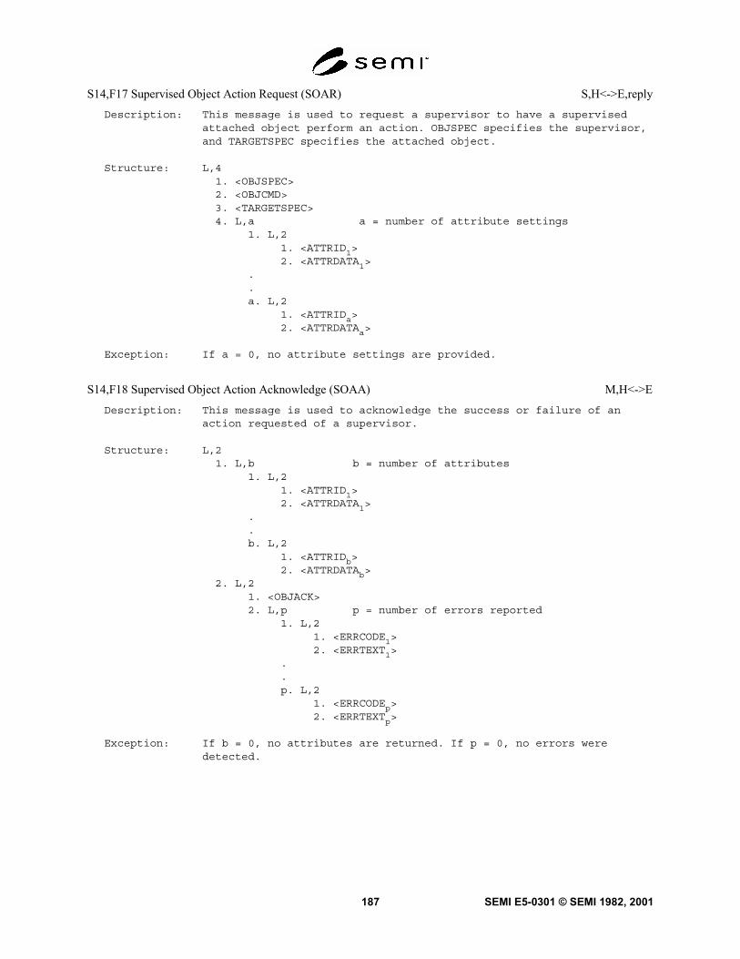
SEMI E5-0301 © SEMI 1982, 2001187
S14,F17 Supervised Object Action Request (SOAR) S,H<->E,reply
Description: This message is used to request a supervisor to have a supervisedattached object perform an action. OBJSPEC specifies the supervisor,and TARGETSPEC specifies the attached object.
Structure: L,41. <OBJSPEC>2. <OBJCMD>3. <TARGETSPEC>4. L,a a = number of attribute settings
1. L,21. <ATTRID1>2. <ATTRDATA1>
.
.a. L,2
1. <ATTRIDa>2. <ATTRDATAa>
Exception: If a = 0, no attribute settings are provided.
S14,F18 Supervised Object Action Acknowledge (SOAA) M,H<->E
Description: This message is used to acknowledge the success or failure of anaction requested of a supervisor.
Structure: L,21. L,b b = number of attributes
1. L,21. <ATTRID1>2. <ATTRDATA1>
.
.b. L,2
1. <ATTRIDb>2. <ATTRDATAb>
2. L,21. <OBJACK>2. L,p p = number of errors reported
1. L,21. <ERRCODE1>2. <ERRTEXT1>
.
.p. L,2
1. <ERRCODEp>2. <ERRTEXTp>
Exception: If b = 0, no attributes are returned. If p = 0, no errors weredetected.

SEMI E5-0301 © SEMI 1982, 2001 188
S14,F19 Generic Service Request (GSR) M,H->E, Reply
Description: The host requests an object to perform the specified service with itsassociated parameters. If multi-block, it shall be preceded by theS14F23/F24 Multi-Block Inquire/Grant transaction. DATAID is givenuniquely to each message. OPID is uniquely specified to identifydelayed completion information for time consuming service. OPIDcould be zero if and only if the service cannot take a long time.
Structure: L,51. <DATAID>2. <OPID>3. <OBJSPEC>4. <SVCNAME>5. L,m # of parameter groups
1. L,21. <SPNAME
1> service parameter 1 name
2. <SPVAL1> service parameter 1 value
2. L,21. <SPNAME
2> service parameter 2 name
2. <SPVAL2> service parameter 2 value
.
.m. L,2
1. <SPNAMEm> service parameter m name
2. <SPVALm> service parameter m value
If a specific value of SPNAME is defined to have a SPVAL defined as a LIST, it shallalways be a LIST. If the SPVAL that is associated to that specific value of SPNAMEis defined to be anything other than LIST, it will result in a format error.
Exception: A zero length list, m = 0, indicates that no parameter groups aresent with the service request. OBJSPEC can be a null length item ifno object provide the services is defined in the standards which arereferred to and it is assumed that “Equipment” is delegated andhandled as if it is an object.
Notes:1. If some service parameters are attributes of the specified object,
service parameter name-value pair, that is SPNAME and SPVAL, isactually attribute id-data pair, that is ATTRID and ATTRDATA. Anexample of parameter part in the message format could be interpretedas below.
L,m1. L,2
1. <SPNAME1>
2. <SPVAL1>
2. L,2...k. L,2
1. <ATTRIDk>
2. <ATTRDATAk>
.m. …
2. If SPVAL is a LIST, the items that make up that list shall take on

SEMI E5-0301 © SEMI 1982, 2001189
one of the following forms: (1) a list of items with an identicalformat, (2) a LIST of SPNAME, SPVAL pairs, as illustrated below.When SPVAL is actually ATTRDATA, even if it is a LIST, it or itsparts are not required to expand into lower level items if theirnames have not been formally named in the corresponding SEMIstandard.
A) L,21. <SPNAME
a>
2. L,m1. <SPVAL
a1>
2. <SPVALa2>
::m. <SPVAL
am>
B) L,21. <SPNAME
b>
2. L, n1. L,2
1. <SPNAMEbl>
2. <SPVALbl>
::n. L,2
1. <SPNANEbn>
2. <SPVALbn>
S14,F20 Generic Service Acknowledge (GSA) M,H<-E
Description: The equipment acknowledges requested service or reports any error(s).If the service is accepted and completed at once, (i.e. SVCACK =0),then required parameter for response are listed with in this message.If the service is accepted but it takes relatively longer time to dodue to some physical reason, (i.e. SVCACK = 4), then response of theservice will be replied later with parameters when it is completedsuccessfully or faultily. Criteria of the time whether it is delayedresponse or not depends on implementation. LINKID is set to a non-zero value if and only if additional completion reports will be sent.
Structure: L,31. <SVCACK>2. <LINKID>3. L,n # of parameter groups
1. L,21. <SPNAME
1> service parameter 1 name
2. <SPVAL1> service parameter 1 value
2. L,21. <SPNAME
2> service parameter 2 name
2. <SPVAL2> service parameter 2 value
::n. L,2
1. <SPNAMEn> service parameter n name
2. <SPVALn> service parameter n value

SEMI E5-0301 © SEMI 1982, 2001 190
S14,F21 Generic Service Completion Information (GSCI) M,H<-E, Reply
Description: The equipment notifies the original service requestor when requestedservice on an object is completed, either successfully orunsuccessfully. The equipment may send required information usingreply parameters. If the service was accepted and completed at once,the information was carried with the acknowledge message, that issecondary message of requesting one, and this message is notprovided.
OPID contains the value of OPID in the initial request, i.e. S14F19.LINKID is set to a non-zero value if and only if additionalcompletion reports with the same OPID will be sent. If multi-block,it shall be preceded by the S14F23/F24 Multi-Block Inquire/Granttransaction.
Structure: L,41. <DATAID>2. <OPID>3. <LINKID>4. L,n # of parameter groups
1. L,21. <SPNAME
1> service parameter 1 name
2. <SPVAL1> service parameter 1 value
2. L,21. <SPNAME
2> service parameter 2 name
2. <SPVAL2> service parameter 2 value
::n. L,2
1. <SPNAMEn> service parameter n name
2. <SPVALn> service parameter n value
S14,F22 Generic Service Completion Acknowledge (GSCA) S,H->E
Description: The acknowledgement of generic Object Service Completion Information,i.e. S14F21.
Structure: <DATAACK>
S14,F23 Multi-block Generic Service Data Inquire (GSDI) S,H<->E, Reply
Description: If any of Object Service messages are larger than one block, thenthis transaction must precede that message.
Structure: L, 21. <DATAID>2. <DATALENGTH>
S14,F24 Multi-block Generic Service Data Grant (GSDG) S,H<->E
Description: Message to indicate if permission is granted to transmit a multi-blockObject Service message.
Structure: <GRANT>

SEMI E5-0301 © SEMI 1982, 2001191
S14,F25 Get Service Name Request (GSNR) S,H->E
Description: This message is used to request to list the services of specifiedtypes of owned objects. This is an operation performed on an objecttype rather than on object instances. Wild characters “?”. and “*” maybe used as a filter for object types. Equipment is not required tosupport wild characters.
Structure: L,21. <OBJSPEC>2. L,n n = # of object types
1. <OBJTYP1>..n. <OBJTYP
n>
Exception: If OBJSPEC is a zero-length item, no object specifier is provided.
S14,F26 Get Service Name Data (GSND) S,H<-E
Description: This message contains a list of the services of the requestedobjects.
Structure: L,21. L,n n = number of object types
1. L,21. <OBJTYP
1>
2. L,a a = number of attributes1. <SVCNAME
1>
.
.a. <SVCNAME
a>
.
.n. L,2
1. <OBJTYPn>
2. L,b b = number of attributes1. <SVCNAME
1>
.
.a. <SVCNAME
b>
2. L,21. L,2
1. <OBJACK>2. L,p p = number of errors reported
1. L,21. <ERRCODE
1>
2. <ERRTEXT1>
.
.p. L,2
1. <ERRCODEp>
2. <ERRTEXTp>
Exception: If p = 0, no errors were detected.

SEMI E5-0301 © SEMI 1982, 2001 192
S14,F27 Get Service Parameter Name Request (GPNR) S,H->E
Description: This message is used to request to list the parameters of specifiedservices of owned object. This is an operation performed on an objecttype rather than on object instances.
Structure: L,31. <OBJSPEC>2. <OBJTYP>3. L,n n = # of interesting services
1. <SVCNAME1>
.
.n. <SVCNAME
n>
Exception: If OBJSPEC is a zero-length item, no object specifier is provided.
S14,F28 Get Service Parameter Name Request (GPND) S,H<-E
Description: This message contains a list of the service parameters of therequested services for the specified object.
Structure: L,21. L,n n = number of object types
1. L,21. <SVCNAME
1>
2. L,a a = number of attributes1. <SPNAME
1>
.
.a. <SPNAME
a>
.
.n. L,2
1. <SVCNAMEn>
2. L,b b = number of attributes1. <SPNAME
1>
.
.b. <SPNAME
b>
2. L,21. <OBJACK>2. L,p p = number of errors reported
1. L,21. <ERRCODE
1>
2. <ERRTEXT1>
.
.p. L,2
1. <ERRCODEp>
2. <ERRTEXTp>
Exception: If p = 0, no errors were detected.

SEMI E5-0301 © SEMI 1982, 2001193
7.19 Stream 15 Recipe Management The functions in this stream are used requesting information and operationsconcerning recipes, recipe namespaces, and recipe executors. A recipe is an object that is transferred in sections,where a section consists of either recipe attributes, agent-specific dataset attributes, or the body of the recipe. Anattribute is information concerning the recipe body, the recipe as a whole, or the application of the recipe. Anattribute consists of an attribute name/attribute value pair.
S15,F0 Abort Transaction (S15F0) S,H<->E
Description: Same form as S1,F0.
S15,F1 Recipe Management Multi-block Inquire S,H<->E, reply
Description: This message requests permission to send a multi-block message basedupon a maximum length of the total message.
Structure: L,31. <DATAID>2. <RCPSPEC>3. <RMDATASIZE>
Exception: If RCPSPEC is zero-length, the multi-block message for whichpermission to send is requested does not contain a recipe.
S15,F2 Recipe Management Multi-block Grant S,H<->E
Description: This message grants or denies permission to send a multi-blockmessage.
Structure: <RMGRNT>
S15,F3 Recipe Namespace Action Request S,H<->E, reply
Description: This message requests that a recipe namespace be created or deleted.
Structure: L,21. <RMNSSPEC>2. <RMNSCMD>
S15,F4 Recipe Namespace Action Acknowledge M,H<->E
Description: This message is used to confirm whether the requested action wascompleted successfully or to provide error information otherwise.
Structure: L,21. <RMACK>2. L,p
1. L,21. <ERRCODE1>2. <ERRTEXT1>
.
.p. L,2
1. <ERRCODEp>2. <ERRTEXTp>
Exception: p = 0 if and only if RMACK indicates no errors.

SEMI E5-0301 © SEMI 1982, 2001 194
S15,F5 Recipe Namespace Rename Request S,H<->E, reply
Description: A request is made for a recipe namespace to be renamed.
Structure: L,21. <RMNSSPEC>2. <RMNEWNS>
S15,F6 Recipe Namespace Rename Acknowledge M,H<->E
Description: This message is used to acknowledge or deny a request to rename arecipe namespace.
Structure: L,21. <RMACK>2. L,p
1. L,21. <ERRCODE1>2. <ERRTEXT1>
.
.p. L,2
1. <ERRCODEp>2. <ERRTEXTp>
Exception: p = 0 if and only if RMACK indicates no errors.
S15,F7 Recipe Space Request S,H<->E, reply
Description: This message requests the amount of recipe storage available in thestorage of a recipe namespace or recipe executor, as indicated byits object specifier OBJSPEC.
Structure: <OBJSPEC>
Exception: None.
S15,F8 Recipe Space Data M,H<->E
Description: This message contains the amount of storage available for recipes.
Structure: L,21. <RMSPACE>2. L,2
1. <RMACK>2. L,p
1. L,21. <ERRCODE1>2. <ERRTEXT1>
.
.p. L,2
1. <ERRCODEp>2. <ERRTEXTp>
Exception: p = 0 if and only if RMACK indicates no errors.

SEMI E5-0301 © SEMI 1982, 2001195
S15,F9 Recipe Status Request S,H<->E, reply
Description: This message is used to request the status of a recipe and the nextavailable numeric version for that recipe class and name.
Structure: <RCPSPEC>
Exception: None.
S15,F10 Recipe Status Data M,H<->E
Description: This message contains the protected status of the recipe and thenext available version number for that recipe class and name.
Structure: L,31. <RCPSTAT>2. <RCPVERS>3. L,2
1. <RMACK>2. L,p
1. L,21. <ERRCODE1>2. <ERRTEXT1>
.
.p. L,2
1. <ERRCODEp>2. <ERRTEXTp>
Exception: RCPVERS is a zero-length item if and only if the recipe does notexist. p = 0 if and only if RMACK indicates no errors.
S15,F11 Recipe Version Request S,H<->E, reply
Description: This message is used to request the best version of a recipe for thespecified agent.
Structure: L,41. <RMNSSPEC>2. <RCPCLASS>3. <RCPNAME>4. <AGENT>
Exception: If item 2 is zero length, the recipe class PROCESS is indicated. Ifitem 4 is a zero-length item, no agent is specified.

SEMI E5-0301 © SEMI 1982, 2001 196
S15,F12 Recipe Version Data M,H<->E
Description: This message contains the recommended version.
Structure: L,31. <AGENT>2. <RCPVERS>3. L,2
1. <RMACK>2. L,p
1. L,21. <ERRCODE1>2. <ERRTEXT1>
.
.p. L,2
1. <ERRCODEp>2. <ERRTEXTp>
Exception: If AGENT is a zero-length item in the request, it shall also be azero-length item in the reply. If it is not zero-length in therequest, and it is of zero-length in the reply, then no qualifyingrecipe was found specific to that equipment. p = 0 if and only ifRMACK indicates no errors.
S15,F13 Recipe Create Request M,H<->E, reply
Description: This message is used to create or modify a recipe body. If multi-block, it shall be preceded by the S15,F1/F2 inquire/granttransaction.
Structure: L,51. <DATAID>2. <RCPUPDT>3. <RCPSPEC>4. L,m
1. L,21. <RCPATTRID1>2. <RCPATTRDATA1>
.
.m. L,2
1. <RCPATTRIDm>2. <RCPATTRDATAm>
5. <RCPBODY>
Exception: RCPBODY may be of zero length.

SEMI E5-0301 © SEMI 1982, 2001197
S15,F14 Recipe Create Acknowledge M,H<->E
Description: This message is used to acknowledge that a recipe has been created orupdated with the body sent in the request.
Structure: L,21. <RMACK>2. L,2
1. L,21. <ERRCODE1>2. <ERRTEXT1>
.
.p. L,2
1. <ERRCODEp>2. <ERRTEXTp>
Exception: p = 0 if and only if RMACK indicates no errors.

SEMI E5-0301 © SEMI 1982, 2001 198
S15,F15 Recipe Store Request M,H<->E, reply
Description: This message is used to send a recipe, or one or more recipesections, to a recipe namespace. If multi-block, it shall bepreceded by the S15,F1/F2 inquire/grant transaction.
Structure: L,41. <DATAID>2. <RCPSPEC>3. <RCPSECCODE>4. L,q (q = 1,2,3)
1. L,r (r = 0 or 2)1. <RCPSECNM>2. L,g (g = # generic attributes)
1. L,21. <RCPATTRID1>2. <RCPATTRDATA1>
.
.g. L,2
1. <RCPATTRIDg>2. <RCPATTRDATAg>
2. <RCPBODY>3. L,m (m = # agent-specific datasets)
1. L,21. <RCPSECNM1>2. L,a
1. L,21. <RCPATTRID11>2. <RCPATTRDATA11>
.
.a. L,2
1. <RCPATTRID1a>2. <RCPATTRDATA1a>
.
.m. L,2
1. <RCPSECNMm>2. L,b
1. L,21. <RCPATTRIDm1>2. <RCPATTRDATAm1>
.
.b. L,2
1. <RCPATTRIDmb>2. <RCPATTRDATAmb>
Exception: RCPBODY is a zero-length item when the body is omitted. If g = 0, nogeneric attributes are transferred and RCPBODY shall be a zero-lengthitem. If m = 0, no agent-specific datasets are transferred.

SEMI E5-0301 © SEMI 1982, 2001199
S15,F16 Recipe Store Acknowledge M,H<->E
Description: This message is used to acknowledge that the specified recipe hasbeen stored as requested or to indicate the error(s).
Structure: L,21. <RECPSECCODE>2. L,2
1. <RMACK>2. L,p
1. L,21. <ERRCODE1>2. <ERRTEXT1>
.
.p. L,2
1. <ERRCODEp>2. <ERRTEXTp>
Exception: p = 0 if and only if RMACK indicates no errors.
S15,F17 Recipe Retrieve Request S,H<->E, reply
Description: This message is used to get a recipe, or one or more recipe sections,from a recipe namespace.
Structure: L,21. <RCPSPEC>2. <RCPSECCODE>
Exception: None.

SEMI E5-0301 © SEMI 1982, 2001 200
S15,F18 Recipe Retrieve Data M,H<->E
Description: This message is used to acknowledge that the specified recipe, orrecipe sections, have been set as requested, or to indicate theerror(s).
Structure: L,21. L,q (q = 1,2,3)
1. L,r (r = 0 or 2)1. <RCPSECNM>2. L,g (g = # generic attributes)
1. L,21. <RCPATTRID1>2. <RCPATTRDATA1>
.g. L,2
1. <RCPATTRIDg>2. <RCPATTRDATAg>
2. <RCPBODY>3. L,m (m = # agent-specific datasets)
1. L,21. <RCPSECNM1>2. L,a
1. L,21. <RCPATTRID11>2. <RCPATTRDATA11>
.
.a. L,2
1. <RCPATTRID1a>2. <RCPATTRDATA1a>
.
.m. L,2
1. <RCPSECNM>m>2. L,b
1. L,21. <RCPATTRIDm1>2. <RCPATTRDATAm1>
.
.b. L,2
1. <RCPATTRIDmb>2. <RCPATTRDATAmb>
2. L,21. <RMACK>2. L,p
1. L,21. <ERROCODE1>2. <ERRTEXT1>
.
.p. L,2
1. <ERRCODEp>2. <ERRTEXTp>
Exception: If r = 0, no generic attributes are transferred and RCPBODY shall bea zero-length item. If m = 0, no agent-specific datasets aretransferred. p = 0 if and only if RMACK indicates no errors.

SEMI E5-0301 © SEMI 1982, 2001201
S15,F19 Recipe Rename Request S,H<->E, reply
Description: This message is used to request that a recipe be copied to, orrenamed to, a recipe with a new identifier.
Structure: L,31. <RCPSPEC>2. <RCPRENAME>3. <RCPNEWID>
Exception: None.
S15,F20 Recipe Rename Acknowledge M,H<->E
Description: This message acknowledges the request to copy or rename a recipe andindicates whether the action was successfully performed or errorsthat occurred.
Structure: L,21. <RMACK>2. L,p
1. L,21. <ERRCODE1>2. <ERRTEXT1>
.
.p. L,2
1. <ERRCODEp>2. <ERRTEXTp>
Exception: p = 0 if and only if RMACK indicates no errors.
S15,F21 Recipe Action Request M,H<->E, reply
Description: This message is used to acknowledge the request to perform an actionon one or more recipes within a namespace.
Structure: L,61. <DATAID>2. <RCPCMD>3. <RMNSSPEC>4. <OPID>5. <AGENT>6. L,n
1. <RCPID1>..n. <RCPIDn>
Exception: AGENT may be a zero-length item except for requests for certify,de-certify, download, and upload.

SEMI E5-0301 © SEMI 1982, 2001 202
S15,F22 Recipe Action Acknowledge M,H<->E
Description: This message is used to acknowledge the request to originate a newrecipe.
Structure: L,41. <AGENT>2. <LINKID>3. <RCPCMD>4. L,2
1. <RMACK>2. L,p
1. L,21. <ERRCODE1>2. <ERRTEXT1>
.
.p. L,2
1. <ERRCODEp>2. <ERRTEXTp>
Exception: LINKID is zero if and only if all requested actions have beencompleted. p = 0 if and only if RMACK indicates no errors.
S15,F23 Recipe Descriptor Request M,H<->E, reply
Description: This message is used to request the descriptors of a list of thespecified recipes. If multi-block, it must be preceded by theS15,F1/F2 inquire/grant transaction. OBJSPEC is the object specifierof either a recipe namespace of a recipe executor.
Structure: L,31. <DATAID>2. <OBJSPEC>3. L,n
1. <RCPID1>..n. <RCPIDn>
Exception: None.

SEMI E5-0301 © SEMI 1982, 2001203
S15,F24 Recipe Descriptor Data M,H<->E
Description: This message returns the requested descriptors in the same order asrequested.
Structure: L,21. L,n (n = number of recipes from request)
1. L,a (descriptors for recipe #1)1. L,r (r = 0 or 3) (1st component descriptor)
1. <RCPDESCNM11>2. <RCPDESCTIME11>3. <RCPDESCLTH11>
.
.a. L,r (r = 0 or 3)
1. <RCPDESCNM1a>2. <RCPDESCTIME1a>3. <RCPDESCLTH1a>
.
.n. L,b (descriptors for recipe #n)
1. L,r (r = 0 or 3) (1st component descriptor)1. <RCPDESCNMn1>2. <RCPDESCTIMEn1>3. <RCPDESCLTHn1>
.
.b. L,r (r = 0 or 3)
1. <RCPDESCNMnb>2. <RCPDESCTIMEnb>3. <RCPDESCLTHnb>
2. L,21. <RMACK>2. L,p
1. L,21. <ERRCODE1>2. <ERRTEXT1>
.
.p. L,2
1. <ERRCODEp>2. <ERRTEXTp>
Exception: A zero-length recipe descriptor (r = 0) means that the specifiedrecipe does not exist (could not be located). p = 0 if and only ifRMACK indicates no errors.

SEMI E5-0301 © SEMI 1982, 2001 204
S15,F25 Recipe Parameter Update Request M,H<->E, reply
Description: This message is used to update the variable parameter definitionsfor a specific agent. If multi-block, it must be preceded by theS15,F1/F2 inquire/grant transaction.
Structure: L,41. <DATAID>2. <RMNSSPEC>3. <AGENT>4. L,n
1. L,31. <RCPPARNM1>2. <RCPPARVAL1>3. <RCPPARRULE1>
.
.n. L,3
1. <RCPPARNMn>2. <RCPPARVALn>3. <RCPPARRULEn>
Exception: None.
S15,F26 Recipe Parameter Update Acknowledge M, H<->E
Description: This message indicates the successful performance of the request orotherwise indicates the nature of error(s) that occurred.
Structure: L,21. <RMACK>2. L,p
1. L,21. <ERRCODE1>2. <ERRTEXT1>
.
.p. L,2
1. <ERRCODEp>2. <ERRTEXTp>
Exception: p = 0 if and only if RMACK indicates no errors.

SEMI E5-0301 © SEMI 1982, 2001205
S15,F27 Recipe Download Request M,H->E,reply
Description: This message is used to send a recipe to a recipe executor. If multi-block, it shall be preceded by the S15,F1/S15,F2 inquire/granttransaction.
Structure: L,51. <DATAID>2. <RCPOWCODE>3. <RCPSPEC>4. L,m
1. L,21. <RCPATTRID1>2. <RCPATTRDATA1>
.
.m. L,2
1. <RCPATTRIDm>2. <RCPATTRDATAm>
5. <RCPBODY>
Exception: None.
S15,F28 Recipe Download Acknowledge M,H<-E
Description: This message is used to acknowledge that a recipe has been receivedby the recipe executor. If the recipe was successfully verified, theresults are returned to the sender. RCPID contains the identifier ofa derived object form recipe if created during verification.
Structure: L,31. <RCPID>2. L,n (n = # of attributes)
1. L,21. <RCPATTRID1>2. <RCPATTRDATA1>
.
.n. L,2
1. <RCPATTRIDn>2. <RCPATTRDATAn>
3. L,21. <RMACK>2. L,p
1. L,21. <ERRCODE1>2. <ERRTEXT1>
.
.p. L,2
1. <ERRCODEp>2. <ERRTEXTp>
Exception: If item is a zero length item, no derived object form recipe wasoriginated. n = 0 if and only if the recipe was not verified orfailed verification. p = 0 if and only if RMACK indicates no errors.
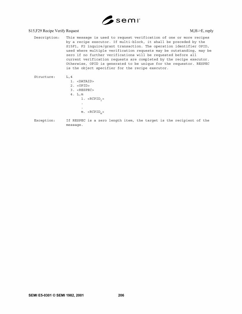
SEMI E5-0301 © SEMI 1982, 2001 206
S15,F29 Recipe Verify Request M,H->E, reply
Description: This message is used to request verification of one or more recipesby a recipe executor. If multi-block, it shall be preceded by theS15F1, F2 inquire/grant transaction. The operation identifier OPID,used where multiple verification requests may be outstanding, may bezero if no further verifications will be requested before allcurrent verification requests are completed by the recipe executor.Otherwise, OPID is generated to be unique for the requestor. RESPECis the object specifier for the recipe executor.
Structure: L,41. <DATAID>2. <OPID>3. <RESPEC>4. L,m
1. <RCPID1>..m. <RCPIDm>
Exception: If RESPEC is a zero length item, the target is the recipient of themessage.

SEMI E5-0301 © SEMI 1982, 2001207
S15,F30 Recipe Verify Acknowledge M,H<-E
Description: This message is used to acknowledge the request to verify one ormore recipes. If a single recipe verification was requested and therecipe was successfully verified, the results are returned to thesender in this message, and RCPID contains the identifier of aderived object form recipe if created during verification. Ifmultiple recipe verifications were requested, then LINKID shall benon-zero.
Structure: L,51. <OPID>2. <LINKID>3. <RCPID>4. L,n (n = # attributes)
1. L,21. <RCPATTRID1>2. <RCPATTRDATA1>
.
.n. L,2
1. <RCPATTRIDn>2. <RCPATTRDATAn>
5. L,21. <RMACK>2. L,p
1. L,21. <ERRCODE1>2. <ERRTEXT1>
.
.p. L,2
1. <ERRCODEp>2. <ERRTEXTp>
Exception: LINKID is zero if and only if a single recipe verification wasrequested and has been completed. If item 3 is zero length item, noderived object form recipe was originated. n = 0 if and only if therecipe was not verified or failed verification. p = 0 if and only ifRMACK indicates no errors.
S15,F31 Recipe Upload Request S,H->E,reply
Description: This message is used to request an execution recipe from a recipeexecutor.
Structure: <RCPSPEC>
Exception: None.

SEMI E5-0301 © SEMI 1982, 2001 208
S15,F32 Recipe Upload Data M,H<-E
Description: This message is used to send an execution recipe from a recipeexecutor.
Structure: L,41. <RCPSPEC>2. L,m (m = # attributes)
1. L,21. <RCPATTRID1>2. <RCPATTRDATA1>
.
.m. L,2
1. <RCPATTRIDm>2. <RCPATTRDATAm>
3. <RCPBODY>4. L,2
1. <RMACK>2. L,p
1. L,21. <ERRCODE1>2. <ERRTEXT1>
.
.p. L,2
1. <ERRCODEp>2. <ERRTEXTp>
Exception: p = 0 if and only if RMACK indicates no errors.

SEMI E5-0301 © SEMI 1982, 2001209
S15,F33 Recipe Select Request M,H->E,reply
Description: This message is used to request the selection of one or moreexecution recipes. If multi-block, it shall be preceded by theS15,F1/S15,F2 inquire/grant transaction.
Structure: L,31. <DATAID>2. <RESPEC>3. L,r (r = # selections)
1. L,21. <RCPID1> (1st recipe selection)2. L,p (p = # parameter settings for 1st recipe)
1. L,21. <RCPPARNM11>2. <RCPPARVAL11>
.
.p. L,2
1. <RCPPARNM1p>2. <RCPPARVAL1p>
.
.r. L,2
1. <RCPIDr> (rth recipe selection)2. L,s (s = # parameter settings for rth recipe)
1. L,21. <RCPPARNMr1>2. <RCPPARVALr1>
.
.s. L,2
1. <RCPPARNMrs>2. <RCPPARVALrs>
Exception: If the list of parameter settings for a recipe selection is of zerolength, then no parameter settings are specified for thecorresponding recipe.
S15,F34 Recipe Select Acknowledge M,H<-E
Description: This message is used to acknowledge the request for recipeselection.
Structure: L,21. <RMACK>2. L,p
1. L,21. <ERRCODE1>2. <ERRTEXT1>
.
.p. L,2
1. <ERRCODEp>2. <ERRTEXTp>
Exception: p = 0 if and only if RMACK indicates no errors.

SEMI E5-0301 © SEMI 1982, 2001 210
S15,F35 Recipe Delete Request M,H->E,reply
Description: This message is used to request that one or more recipes be deletedor deselected. If multi-block, it shall be preceded by the S15,F1/S15,F2 inquire/grant transaction.
Structure: L,41. <DATAID>2. <RESPEC>3. <RCPDEL>4. L,n (n = # recipes deselected)
1. <RCPID1>..n. <RCPIDn>
Exception: If n = 0 and recipes are to be deselected (RCPDEL = 1), then allcurrently-selected recipes are indicated.
S15,F36 Recipe Delete Acknowledge M,H<-E
Description: This message is used to acknowledge the request that recipes bedeleted or deselected.
Structure: L,21. <RMACK>2. L,p
1. L,21. <ERRCODE1>2. <ERRTEXT1>
.
.p. L,2
1. <ERRCODEp>2. <ERRTEXTp>
Exception: p = 0 if and only if RMACK indicates no errors.
S15,F37 DRNS Segment Approve Action Request S,H<->E,reply
Description: This message is sent by a distributed recipe namespace manager to anattached distributed recipe namespace segment to approve an actionpreviously requested by the segment. If multi-block, it shall bepreceded by the S15,F1/S15,F2 inquire/grant transaction.
Structure: L,61. <RMSEGSPEC>2. <OBJTOKEN>3. <RMGRNT>4. <OPID>5. <RCPID>6. <RMCHGTYPE>
Exception: None.

SEMI E5-0301 © SEMI 1982, 2001211
S15,F38 DRNS Segment Approve Action Acknowledge M,H<->E
Description: This message is used to acknowledge or deny the approve actionrequest.
Structure: L,21. <RMACK>2. L,p
1. L,21. <ERRCODE1>2. <ERRTEXT1>
.
.p. L,2
1. <ERRCODEp>2. <ERRTEXTp>
Exception: p = 0 if and only if RMACK indicates no errors.
S15,F39 DRNS Recorder Segment Request M,H<->E,reply
Description: This message is used by the distributed recipe namespace manager torequest that an attached recorder create or delete a segmentspecifier record. If multi-block, it shall be preceded by the S15,F1/S15,F2 inquire/grant transaction.
Structure: L,51. <DATAID>2. <RMNSCMD>3. <RMRECSPEC>4. <RMSEGSPEC>5. <OBJTOKEN>
Exception: None.
S15,F40 DRNS Recorder Segment Acknowledge M,H<->E
Description: This message is used to acknowledge the request to add or delete asegment specifier record.
Structure: L,21. <RMACK>2. L,p
1. L,21. <ERRCODE1>2. <ERRTEXT1>
.
.p. L,2
1. <ERRCODEp>2. <ERRTEXTp>
Exception: p = 0 if and only if RMACK indicates no errors.

SEMI E5-0301 © SEMI 1982, 2001 212
S15,F41 DRNS Recorder Modify Request M,H<->E,reply
Description: This message is used by a distributed recipe namespace manager toa recorder to store or delete a change request record. If multi-block, it shall be preceded by the S15,F1/F2 inquire/granttransaction.
Structure: L,51. <DATAID>2. <RMRECSPEC>3. <OBJTOKEN>4. <RMNSCMD>5. L,c (c = 1 or 7)
1. <RCPID>2. <RCPNEWID>3. <RMSEGSPEC>4. <RMCHGTYPE>5. <OPID>6. <TIMESTAMP>7. <RMREQUESTOR>
Exception: If RMNSCMD = create, then c = 7, otherwise c = 1.
S15,F42 DRNS Recorder Modify Acknowledge M,H<->E
Description: This message is used to acknowledge a request to store or delete achange request.
Structure: L,21. <RMACK>2. L,p
1. L,21. <ERRCODE1>2. <ERRTEXT1>..
p. L,21. <ERRCODEp>2. <ERRTEXTp>
Exception: p = 0 if and only if RMACK indicates no errors.
S15,F43 DRNS Get Change Request M,H<->E,reply
Description: This message is used to request a distributed recipe namespacerecorder or manager to return change requests records for a specificrecipe or assigned to a specific segment. If multi-block, it shall bepreceded by the S15,F1/F2 inquire/grant transaction.
Structure: L,31. <DATAID>2. <OBJSPEC>3. <TARGETSPEC>
Exception: If TARGETSPEC is omitted, OBJSPEC identifies a recipe.
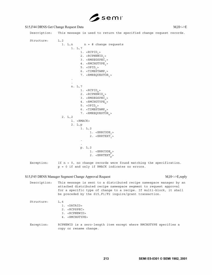
SEMI E5-0301 © SEMI 1982, 2001213
S15,F44 DRNS Get Change Request Data M,H<->E
Description: This message is used to return the specified change request records.
Structure: L,21. L,n n = # change requests
1. L,71. <RCPID1>2. <RCPNEWID1>3. <RMSEGSPEC1>4. <RMCHGTYPE1>5. <OPID1>6. <TIMESTAMP1>7. <RMREQUESTOR1>
.
.n. L,7
1. <RCPIDn>2. <RCPNEWIDn>3. <RMSEGSPECn>4. <RMCHGTYPEn>5. <OPIDn>6. <TIMESTAMPn>7. <RMREQUESTORn>
2. L,21. <RMACK>2. L,p
1. L,21. <ERRCODE1>2. <ERRTEXT1>
.
.p. L,2
1. <ERRCODEp>2. <ERRTEXTp>
Exception: If n = 0, no change records were found matching the specification.p = 0 if and only if RMACK indicates no errors.
S15,F45 DRNS Manager Segment Change Approval Request M,H<->E,reply
Description: This message is sent to a distributed recipe namespace manager by anattached distributed recipe namespace segment to request approvalfor a specific type of change to a recipe. If multi-block, it shallbe preceded by the S15,F1/F2 inquire/grant transaction.
Structure: L,41. <DATAID>2. <RCPSPEC>3. <RCPNEWID>4. <RMCHGTYPE>
Exception: RCPNEWID is a zero-length item except where RMCHGTYPE specifies acopy or rename change.

SEMI E5-0301 © SEMI 1982, 2001 214
S15,F46 DRNS Manager Segment Approval Acknowledge S,H<->E
Description: This message is used to acknowledge the request to change a recipe.
Structure: L,31. <RMCHGTYPE>2. <RMGRNT>3. <OPID>
Exception: OPID is zero if and only if RMGRNT indicates the change is denied.
S15,F47 DRNS Manager Rebuild Request M,H<->E, reply
Description: This message requests a distributed recipe namespace manager speci-fied in OBJSPEC to rebuild a distributed recipe namespace. Either adistributed recipe namespace recorder or a list of distributedrecipe namespace segment specifiers shall be provided.If multi-block, it shall be preceded by the S15,F1/F2 inquire/granttransaction.
Structure: L,51. <DATAID>2. <OBJSPEC>3. <RMNSSPEC>4. <RMRECSPEC>5. L,n
1. <RMSEGSPEC1>..n. <RMSEGSPECn>
Exception: If RMRECSPEC is a non-zero length item, then n is zero. If RMRECSPECis a zero length item, then n is non-zero.
S15,F48 DRNS Manager Rebuild Acknowledge M,H<->E
Description: This message is used to acknowledge the request to rebuild adistributed recipe namespace.
Structure: L,21. <RMACK>2. L,P
1. L,21. <ERRCODE1>2. <ERRTEXT1>
.
.p. L,2
1. <ERRCODEp>2. <ERRTEXTp>
Exception: p = 0 if and only if RMACK indicates no errors.

SEMI E5-0301 © SEMI 1982, 2001215
7.20 Steam 16 Processing Management — This stream provides protocol for a set of messages that enable thecontrol of material processing at equipment and equipment resources. Control is implemented by supporting twojob types; the control job and the process job. A process job is a single unit of work that ensures that the appropriateprocessing is applied to a particular material by a processing resource. The Process Job provides a widely applicablesupervisory control capability for automated processing of material in equipment, irrespective of the particularprocess being used. The Process Job creates a transient link between the three elements of the manufacturingprocess; the first is the material to be processed. The second is the equipment on which the process will occur. Thethird is the process specification, a Process Recipe. When a Process Job has completed, it ceases to exist; its ProcessJob ID is no longer valid. The control job is used to group a set of related process jobs. The group is logicallyrelated from the host’s viewpoint. For instance; if a carrier contains multiple lots, then the process jobs for each lot(in the carrier) could be included in the control job specification. Control jobs also provide mechanisms forspecifying the destination for processed material.
S16,F0 Abort Transaction (S16F0) S,H<->E
Description: Same form as S1F0.
S16,F1 Multi-block Process Job Data Inquire (PRJI) S,H->E,reply
Description: If any of Processing Management messages are larger than one block,then this transaction must precede that message.
Structure: L,21. <DATAID>2. <DATALENGTH>
S16,F2 Multi-block Process Job Data Grant (PRJG) S,H<-E
Description: Message to indicate if permission is granted to transmit a multi-block Job Data message.
Structure: <GRANT>

SEMI E5-0301 © SEMI 1982, 2001 216
S16,F3 Process Job Create Request (PRJCR) M,H->E,reply
Description: The purpose of this message is to request material to be processedon a Process Module.
Structure: L,51. <DATAID>2. <MF>3. L,n
1. <MID1>..n. <MIDn>
4. L,31. <PRRECIPEMETHOD>2. <RCPSPEC>3. L,m (m = {c,2})
1. L,21. <RCPPARNM1>2. <RCPPARVAL1>
.
.
.m. L,2
1. <RCPPARNMm>2. <RCPPARVALm>
5. <PRPROCESSSTART>
Exception: For the m length list m = 0 may be allowed value depending onthe value of PRRECIPEMETHOD.
S16,F4 Process Job Create Acknowledge (PRJCA) S,H<-E
Description: Acknowledge or report error in the creation of a Process Job.
Structure: L,21. <PRJOBID>2. L,2
1. <ACKA>2. L,n
1. L,21. <ERRCODE1>2. <ERRTEXT1>
.
.
.n. L,2
1. <ERRCODEn>2. <ERRTEXTn>
Exception: This list may be zero length, generally the case when ACKA indicatessuccess. When ACKA indicates a create failure, the equipmentmay supply one or more ERRCODE’s.

SEMI E5-0301 © SEMI 1982, 2001217
S16,F5 Process Job Command Request (PRJCMDR) M,H->E,reply
Description: Send a job control command to a processing job.
Structure: L,41. <DATAID>2. <PRJOBID>3. <PRCMDNAME>4. L,n
1. L,21. <CPNAME1>2. <CPVAL1>
.
.
.n. L,2
1. <CPNAMEn>2. <CPVALn>
Exception: The CPNAME, CPVAL pairs are command parameter identifiers andvalues; n = 0 is valid for some commands (PRCMDNAME).
S16,F6 Process Job Command Acknowledge (PRJCMDA) S,H<-E
Description: The processing service sends its confirmation for receipt of acommand request.
Structure: L,21. <PRJOBID>2. L,2
1. <ACKA>2. L,n (n = {0,n})
1. L,21. <ERRCODE1>2. <ERRTEXT1>
.
.
.n. L,2
1. <ERRCODEn>2. <ERRTEXTn>
Exception: This list n may be zero length.

SEMI E5-0301 © SEMI 1982, 2001 218
S16,F7 Process Job Alert Notify (PRJA) S,H<-E,[reply]
Description: The processing service may notify the controlling entity ofimportant events. The Process Job Milestones only assume smallnumber of different values. However, the conditions under which aprocess job meets one of these milestones may vary. For instance, aJob may reach Job Complete because the Process was Aborted. By usingitem 4, the status of the Alert (PRJOBMILESTONE) can be indicated.See the list of Error Codes for Processing in Data Item Dictionary.
Structure: L,41. <TIMESTAMP>2. <PRJOBID>3. <PRJOBMILESTONE>4. L,2
1. <ACKA>2. L,n (n = {0,n})
1. L,21. <ERRCODE1>2. <ERRTEXT1>
.
.
.n. L,2
1. <ERRCODEn>2. <ERRTEXTn>
Exception: The list n may be zero length.
S16,F8 Process Job Alert Confirm (PRJAC) S,H->E
Description: Host confirms receipt of Process Job Alert message from theequipment.
Structure: Header only
S16,F9 Process Job Event Notify (PRJE) S,H<-E,[reply]
Description: Send Processing Job related event to the controlling entity.
Structure: L,41. <PREVENTID>2. <TIMESTAMP>3. <PRJOBID>4. L,n
1. L,21. <VID1>2. <V1>
.
.
.n. L,2
1. <VIDn>2. <Vn>
Exception: The VID, V pairs are variable data identifiers and values; exceptionsn = 0 is valid for some events (PREVENTID).

SEMI E5-0301 © SEMI 1982, 2001219
S16,F10 Process Job Event Confirm (PRJEC) S,H->E
Description: Host confirms receipt of S16,F9 message to equipment.
Structure: Header only.
S16,F11 PRJobCreateEnh M,H->E,reply
Description: Request equipment to create a Process Job with the given PRJOBID. Ifmulti-block, this message must be preceded by the S16,F1/F2transaction.
Structure: L,71. <DATAID>2. <PRJOBID>3. <MF>4a. L,n [MF = carrier, n = # of carriers]
1. L,21. <CARRIERID
1>
2. L,j [j = # of slots, may be implemented as anarray]
1. <SLOTID1>
2. <SLOTID2>
.j. <SLOTID
j>
.
.n. L,2
1. <CARRIERIDn>
2. L,j [j = # of slots, may be implemented as anarray]
1. <SLOTID1>
2. <SLOTID2>
.j. <SLOTID
j>
4b. L,n [MF = substrate]1. <MID
1>
.
.n. <MID
n>
5. L,31. <PRRECIPEMETHOD>2. <RCPSPEC>3. L,m [m = # recipe parameters]
1. L,21. <RCPPARNM
1>
2. <RCPPARVAL1>
.m. L,2
1. <RCPPARNMm>
2. <RCPPARVALm>
6. <PRPROCESSSTART>7. <PRPAUSEEVENT>
Exception: The list for specifying material (item 4a and 4b) is empty (L,0instead of L,n), when no material is specified for the process job.The form of data item 4(a or b) depends on the value in MF.

SEMI E5-0301 © SEMI 1982, 2001 220
S16,F12 PRJobCreateEnh Acknowledge S,H<-E
Description: This message acknowledges the request and reports any errors in thecreation of a process job.
Structure: L,21. <PRJOBID>2. L,2
1. <ACKA>2. L,n
1. L,21. <ERRCODE
1>
2. <ERRTEXT1>
.
.n. L,2
1. <ERRCODEn>
2. <ERRTEXTn>
Exception: If n = 0, no errors exist.
S16,F13 PRJobDuplicateCreate M,H->E,reply
Description: This function creates multiple process jobs. The same recipe andvalue of PRProcessStart are applied to each process job created. Ifmulti-block, this message must be preceded by the S16,F1/F2transaction.
Structure: L,51. <DATAID>2. L,p [p = # of process jobs being created]
1. L,31. <PRJOBID
1>
2. <MF1>
3a. L,n [MF = carrier, n = # of carriers]1. L,2
1. <CARRIERID1>
2. L,j [j = # of slots, may be implementedas an array]
1. <SLOTID1>
2. <SLOTID2>
.j. <SLOTID
j>
.
.n. L,2
1. <CARRIERIDn>
2. L,j [j = # of slots, may be implementedas an array]
1. <SLOTID1>
2. <SLOTID2>
.j. <SLOTID
j>
3b. L,n [MF = substrate, n = # of MID]1. <MID
1>
.n. <MID
n>
.
.

SEMI E5-0301 © SEMI 1982, 2001221
p. L,31. <PRJOBID
p>
2. <MFp>
3a. L,n [MF = carrier, n = # of carriers]1. L,2
1. <CARRIERID1>
2. L,j [j = # of slots, may be implementedas an array]
1. <SLOTID1>
2. <SLOTID2>
.j. <SLOTID
j>
.
.n. L,2
1. <CARRIERIDn>
2. L,j [j = # of slots, may be implementedas an array]
1. <SLOTID1>
2. <SLOTID2>
.j. <SLOTID
j>
3b. L,n [MF = substrate, n = # of MID]1. <MID
1>
.n. <MID
n>
3. L,31. <PRRECIPEMETHOD>2. <RCPSPEC>3. L,m [m = # recipe parameters]
1. L,21. <RCPPARNM
1>
2. <RCPPARVAL1>
.m. L,2
1. <RCPPARNMm>
2. <RCPPARVALm>
4. <PRPROCESSSTART>5. <PRPAUSEEVENT>
Exception: The list for specifying material (item 3a and 3b) is empty (L,0instead of L,n), when no material is specified for the process job.The form of data item 3(a or b) depends on the value in MF.

SEMI E5-0301 © SEMI 1982, 2001 222
S16,F14 PRJobDuplicateCreate Acknowledge S,H<-E
Description: This message acknowledges the request and reports any errors in thecreation of a process job. ERRTEXT contains the identifier of processjobs that were not created.
Structure: L,21. L,m [m = # of jobs created]
1. <PRJOBID1>
.m. <PRJOBID
m>
2. L,21. <ACKA>2. L,n
1. L,21. <ERRCODE
1>
2. <ERRTEXT1>
.
.n. L,2
1. <ERRCODEn>
2. <ERRTEXTn>
Exception: If n = 0, no errors exist.
S16,F15 PRJobMultiCreate M,H->E,reply
Description: Use this single message to Create Multiple Process Jobs, each ofwhich may be unique in its association of material to processrecipe. If multi-block, this message must be preceded by theS16,F1/F2 transaction.
Structure: L,21. <DATAID>2. L,p [p = # of process jobs being created]
1. L,61. <PRJOBID
1>
2. <MF1>
3a. L,n [MF = carrier, n = # of carriers]1. L,2
1. <CARRIERID1>
2. L,j [j = # of slots, may be implementedas an array]
1. <SLOTID1>
2. <SLOTID2>
.j. <SLOTID
j>
.
.n. L,2
1. <CARRIERIDn>
2. L,j [j = # of slots, may be implementedas an array]
1. <SLOTID1>
2. <SLOTID2>
.j. <SLOTID
j>

SEMI E5-0301 © SEMI 1982, 2001223
3b. L,n [MF = substrate, n = # of MID]1. <MID
1>
.n. <MID
n>
4. L,31. <PRRECIPEMETHOD
1>
2. <RCPSPEC1>
3. L,m [m = # recipe parameters]1. L,2
1. <RCPPARNM1>
2. <RCPPARVAL1>
.m. L,2
1. <RCPPARNMm>
2. <RCPPARVALm>
5. <PRPROCESSSTART1>
6. <PRPAUSEEVENT1>
.
.p. L,6
1. <PRJOBIDp>
2. <MFp>
3a. L,n [MF = carrier, n = # of carriers]1. L,2
1. <CARRIERID1>
2. L,j [j = # of slots, may be implementedas an array]
1. <SLOTID1>
2. <SLOTID2>
.j. <SLOTID
j>
.
.n. L,2
1. <CARRIERIDn>
2. L,j [j = # of slots, may be implementedas an array]
1. <SLOTID1>
2. <SLOTID2>
.j. <SLOTID
j>
3b. L,n [MF = substrate, n = # of MID]1. <MID
1>
.n. <MID
n>
4. L,31. <PRRECIPEMETHOD
p>
2. <RCPSPECp>
3. L,m [m = # recipe parameters]1. L,2
1. <RCPPARNM1>
2. <RCPPARVAL1>
.m. L,2
1. <RCPPARNMm>
2. <RCPPARVALm>
5. <PRPROCESSSTARTp>
6. <PRPAUSEEVENTp>

SEMI E5-0301 © SEMI 1982, 2001 224
Exception: The list for specifying material (item 3a and 3b) is empty (L,0instead of L,n), when no material is specified for the process job.The form of data item 3(a or b) depends on the value in MF.
S16,F16 PRJobMultiCreate Acknowledge S,H<-E
Description: This message acknowledges the request and reports any errors in thecreation of a process job. ERRTEXT contains the identifier of processjobs that were not created.
Structure: L,21. L,m [m = # jobs created]
1. <PRJOBID1>
.m. <PRJOBID
m>
2. L,21. <ACKA>2. L,n
1. L,21. <ERRCODE
1>
2. <ERRTEXT1>
.
.n. L,2
1. <ERRCODEn>
2. <ERRTEXTn>
Exception: If n = 0, no errors exist.
S16,F17 PRJobDequeue S,H->E,reply
Description: Used to remove process jobs from the equipment for jobs that have notbegun processing.
Structure: L,m [m = # jobs to remove]1. <PRJOBID
1>
.m. <PRJOBID
m>
Exception: If m = 0, then de-queue all.

SEMI E5-0301 © SEMI 1982, 2001225
S16,F18 PRJobDequeue Acknowledge S,H<-E
Description: Acknowledge the request to de-queue and report any errors. ERRTEXTwill contain the identifier of any jobs that were not de-queued.
Structure: L,21. L,m [m = # jobs removed]
1. <PRJOBID1>
.m. <PRJOBID
m>
2. L,21. <ACKA>2. L,n
1. L,21. <ERRCODE
1>
2. <ERRTEXT1>
.
.n. L,2
1. <ERRCODEn>
2. <ERRTEXTn>
Exception: If n = 0, no errors exist.
S16,F19 PRGetAllJobs S,H->E
Description: Requests the equipment to return a list of process jobs which havenot completed. They may be running or waiting to run.
Structure: header only
S16,F20 PRGetAllJobs Send S,H<-E
Description: Returns the requested list of process jobs.
Structure: L,m [m = # jobs in the list]1. L,2
1. <PRJOBID1>
2. <PRSTATE1>
.m. L,2
1. <PRJOBIDm>
2. <PRSTATEm>
Exception: If m = 0, then no process jobs are running or waiting to run.
S16,F21 PRGetSpace S,H->E
Description: Requests the equipment to return the number of process jobs it hasspace to create.
Structure: header only

SEMI E5-0301 © SEMI 1982, 2001 226
S16,F22 PRGetSpace Send S,H<-E
Description: Sends the host the number of process jobs which can be created.
Structure: <PRJOBSPACE>
S16,F23 PRJobSetRecipeVariable S,H->E
Description: Reset the value of recipe variable parameters for a specific processjob.
Structure: L,21. <PRJOBID>2. L,m [m = # recipe variables]
1. L,21. <RCPPARNM
1>
2. <RCPPARVAL1>
.
.m. L,2
1. <RCPPARNMm>
2. <RCPPARVALm>
S16,F24 PRJobSetRecipeVariable Acknowledge S,H<-E
Description: Indicate the status of the request to set recipe variables. ERRTEXTwill contain the RCPPARNM value for parameters that could not bereset.
Structure: L,21. <ACKA>2. L,n
1. L,21. <ERRCODE
1>
2. <ERRTEXT1>
.
.n. L,2
1. <ERRCODEn>
2. <ERRTEXTn>
Exception: If n = 0, no errors exist.
S16,F25 PRJobSetStartMethod S,H->E
Description: Used to request to change the start method (USERSTART or AUTO) forone or more process jobs.
Structure: L,21. L,m [m = # of jobs]
1. <PRJOBID1>
.
.m. <PRJOBID
m>
2. <PRPROCESSSTART>

SEMI E5-0301 © SEMI 1982, 2001227
S16,F26 PRJobSetStartMethod Acknowledge S,H<-E
Description: Acknowledges request to set job start method and indicates anyerrors. ERRTEXT will contain the identifiers of any process jobsthat did not accept the new process start method.
Structure: L,21. L,m [m = # of jobs]
1. <PRJOBID1>
.m. <PRJOBID
m>
L,21. <ACKA>2. L,n
1. L,21. <ERRCODE
1>
2. <ERRTEXT1>
.
.n. L,2
1. <ERRCODEn>
2. <ERRTEXTn>
S16,F27 Control Job Command Request S,H->E
Description: Send a control job command to a control job.
Structure: L,31. <CTLJOBID>2. <CTLJOBCMD>3. L,2
1. <CPNAME>2. <CPVAL>
Exception: 3. L,2 IS L,0 for commands that do not need parameters.
S16,F28 Control Job Command Acknowledge S,H<-E
Description: Indicates success or failure of command request to a control job. Ifapplicable ERRTEXT shall contain information on specific commandparameter names or values that caused the error.
Structure: L,21. <ACKA>2. L,2
1. <ERRCODE>2. <ERRTEXT>
Exception: 2. L,2 IS L,0 if no errors.
S16,F29 PRSetMtrlOrder (PRJSMO) S,H -> E,reply
Description: This message requests the equipment’s Processing Management Serviceto use a specific strategy for the order in which materials areprocessed.
Structure: <PRMTRLORDER>

SEMI E5-0301 © SEMI 1982, 2001 228
S16,F30 PRSetMtrlOrder Acknowledge (PRJSMOA) S,H <- E
Description: This message acknowledges the request for change to the materialprocess strategy by reporting back the value requested, if correct.
Structure: <ACKA>
7.21 Stream 17 Equipment Control and Diagnostics — This stream is a continuation of Stream 2.
S17,F0 Abort Transaction (S17F0) S,H<->E
Description: Same form as S1F0.
S17,F1 Data Report Create Request (DRC) M,H->E,reply
Description: Create a Data Report definition. This function allows thereferencing of a Data Source for the items (variables or attributes)specified in the data report.
Structure: L,41. <DATAID>2. <RPTID>3. <DATASRC>4. L,n
1. <VID1>2. <VID2>...n. <VIDn>
Exception: DATAID is a zero length item when the request can be sent in a singleblock. If RPTID is a zero length item, then the equipment shallreturn a value in RPTID by which the host can then reference thereport efinition. If RPTID has a value, then the equipment shallretain this value by which the host can then reference the reportdefinition.
S17,F2 Data Report Create Acknowledge (DRCA) S,H<-E
Description: Equipment confirms creation of a Data Report and returns RPTID.
Structure: L,21. <RPTID>2. <ERRCODE>
Exception: If ERRCODE is a zero length item, then no error occurred.

SEMI E5-0301 © SEMI 1982, 2001229
S17,F3 Data Report Delete Request (DRD) S,H->E,reply
Description: Delete one or more data reports. This shall cause those reports tobe unlinked from any Event Reports to which they were linked. Thisshall cause the report to be excluded from any Trace Reports for inwhich it had originally been included.
Structure: L,n1. <RPTID1>2. <RPTID2>...n. <RPTIDn>
Exception: If this message is sent with a zero length list, then all reportsshall be deleted.
S17,F4 Data Report Delete Acknowledge (DRDA) S,H<-E
Description: Equipment confirms or indicates any errors on the request to deleteData Reports. All Data Reports which could be deleted shall belisted in the response and the associated error code shall beincluded in the list.
Structure: L,21. <ACKA>2. L,m
1. L,31. <RPTID1>2. <ERRCODE1>3. <ERRTEXT1>
.
.m. L,3
1. <RPTIDm>2. <ERRCODEm>3. <ERRTEXTm>
Exception: If ACKA is TRUE, then no errors were encountered, meaning all reportrequests were completed successfully and a zero-length list (m = 0)shall be sent.
Exception: If some reports could not be deleted, then their RPTID’s shall begiven in a space separated list in ERRTEXT.

SEMI E5-0301 © SEMI 1982, 2001 230
S17,F5 Trace Create Request (TRC) M,H->E,reply
Description: Establish a Trace Report definition.
Structure: L,61. <DATAID>2. <TRID>3. <CEED>4. L,n
1. <RPTID1>2. <RPTID2>..n. <RPTIDn>
5. <TRSPER>6. L,m (m = {0,8})
1. <TOTSMP>2. <REPGSZ>3. <EVNTSRC> (Defines source for start Event)4. <CEID> (Defines ID of the start Event)5. <EVNTSRC> (Defines source for stop Event)6. <CEID> (Defines ID of the stop Event)7. <TRAUTOD>8. <RPTOC>
Exception: The list m can be zero-length, or it can contain all eight dataitems. Since specifying values for each item is optional, each ofthe eight items can be zero-length. If the item is zero-length, theformat of the item shall be the same format used in other instancesof the S17,F5 message where the value is not zero-length.
S17,F6 Trace Create Acknowledge (TRCA) S,H<-E
Description: Equipment confirms creation of an Event Report and returns a TRID.
Structure: L,21. <TRID>2. <ERRCODE>
Exception: If ERRCODE is a zero length item, then no error occurred.
S17,F7 Trace Delete Request (TRD) S,H->E,reply
Description: The host requests to delete one or more Trace Reports.
Structure: L,n1. <TRID1>2. <TRID2>..n. <TRIDn>

SEMI E5-0301 © SEMI 1982, 2001231
S17,F8 Trace Delete Acknowledge (TRDA) S,H<-E
Description: This message is required to inform the host when a Trace Reportcould not be deleted. This message does not need to be sent toconfirm the successful deletion of a Trace Report. If the report issent for a successfully deleted Trace Report, then the ERRCODE itemlength shall be set to zero.
Structure: L,21. <ACKA>2. L,m
1. L,31. <TRID1>2. <ERRCODE1>3. <ERRTEXT1>
.
.m. L,3
1. <TRIDm>2. <ERRCODEm>3. <ERRTEXTm>
Exception: If ACKA is TRUE, then no errors were encountered, meaning all reportrequests were completed successfully and a zero-length list (m = 0)shall be sent.
Exception: If some reports could not be deleted, then their TRID’s shall beprovided in a space separated list in ERRTEXT.
S17,F9 Collection Event Link Request (CELR) M,H->E,reply
Description: Establish a Collection Event Report definition with respect to aspecific Event Source.
Structure: L,41. <DATAID>2. <EVNTSRC>3. <CEID>4. L,n (n is the number of Reports to be linked)
1. <RPTID1>2. <RPTID2>..n. <RPTIDn>
S17,F10 Collection Event Link Acknowledge (CELA) S,H<-E
Description: Indicate the success or failure of a Collection Event Link Request.
Structure: L,31. <EVNTSRC>2. <CEID>3. <ERRCODE>
Exception: Item 3 should be set to zero length to indicate success.

SEMI E5-0301 © SEMI 1982, 2001 232
S17,F11 Collection Event Unlink Request (CEUR) S,H->E,reply
Description: Request to unlink a specific Data Report from a Collection EventReport.
Structure: L,31. <EVNTSRC>2. <CEID>3. <RPTID>
Exception: Item one can be zero length, in which case the default event sourceis assumed.
S17,F12 Collection Event Unlink Acknowledge (CEUA) S,H<-E
Description: Indicates success or failure of a requested Unlink.
Structure: L,41. <EVNTSRC>2. <CEID>3. <RPTID>4. <ERRCODE>
Exception: Item one can be zero length to indicate the default event source.Item 4 is set to zero length if the primary request was successful.
S17,F13 Trace Reset Request (TRR) S,H->E,reply
Description: The Host requests the equipment to clear the data and reset thespecified trace reports. If n = 0, then all defined Trace Objectswill be reset.
Structure: L,n1. <TRID1>2. <TRID2>..n. <TRIDn>

SEMI E5-0301 © SEMI 1982, 2001233
S17,F14 Trace Report Reset Acknowledge (TRRA) S,H<-E
Description: This list in item 1 contains the identifiers of all the TraceObjects which were reset. If all Trace Objects are successfullyreset, then ACKA shall be set to TRUE.
Structure: L,21. <ACKA>2. L,m
1. L,31. <TRID1>2. <ERRCODE1>3. <ERRTEXT1>
.
.m. L,3
1. <TRIDm>2. <ERRCODEm>3. <ERRTEXTm>
Exception: If ACKA is TRUE, then no errors were encountered, meaning all reportrequests were completed successfully and a zero-length list (m = 0)shall be sent.
Exception: If some reports could not be reset, then their TRID’s shall be givenin a space separated list in ERRTEXT.
7.22 Stream 18 Subsystem Control and Data — Messages exchanged between component subsystems and higherlevel controllers. Compared to similar messages exchanged between equipment and host, subsystem messages areless complex.
S18,F1 Read Attribute Request (RAR) S,H->E,reply
Description: This message requests the current values of specified attributes ofthe subsystem component indicated in TARGETID.
Structure: L,21. <TARGETID>2. L,n n = # attribute identifiers
1. <ATTRID1>.n. <ATTRIDn>
Exceptions: If n = 0, then all attributes of the target component are requested.

SEMI E5-0301 © SEMI 1982, 2001 234
S18,F2 Read Attribute Data (RAD) S,H<-E
Description: This message returns the current values of requested attributes andthe current status of the requested component indicated in TARGETID.Attributes are returned in the order requested.
Structure: L,31. <TARGETID>2. <SSACK>3. L,n
1. <ATTRDATA1>.n. <ATTRDATAn>
Exceptions: Both n = 0 and s = 0 if the target component is unknown.
S18,F3 Write Attribute Request (WAR) S,H->E,reply
Description: This message requests the subsystem to set the value of read/writeattributes of the component specified in TARGETID.
Structure: L,21. <TARGETID>2. L,n
1. L,21. <ATTRID1>2. <ATTRDATA1>
.n. L,2
1. <ATTRIDn>2. <ATTRDATAn>
S18,F4 Write Attribute Acknowledge (WAA) S,H<-E
Description: This message acknowledges the success of failure of the request towrite attribute data to the subsystem indicated in TARGETID.
Structure: L, 31. <TARGETID>2. <SSACK>3. <STATUSLIST>
Exceptions: s = 0 if the target component is unknown.

SEMI E5-0301 © SEMI 1982, 2001235
S18,F5 Read Request (RR) S,H->E,reply
Description: The host requests the subsystem indicated in TARGETID to readinformation. DATASEG may be used to indicate a specific section ofdata to be read. DATALENGTH is used to limit the amount of data forthat section.
Structure: L,31. <TARGETID>2. <DATASEG>3. <DATALENGTH>
Exceptions: If DATASEG and DATALENGTH are both omitted (are zero length items)then all data is requested. If DATALENGTH only is omitted, then alldata within the indicated section is requested.
S18,F6 Read Data (RD) S,H<-E
Description: This message is used to return requested information from thesubsystem indicated in TARGETID or to acknowledge the results of therequest.
Structure: L,31. <TARGETID>2. <SSACK>3. <DATA>
Exceptions: If TARGETID is unknown, then DATA is zero length.
S18,F7 Write Data Request (WDR) S,H->E,reply
Description: This message requests to write data to the subsystem componentindicated in TARGETID. DATASEG may be used to indicate a specificsection of data to be written or overwritten.
Structure: L,41. <TARGETID>2. <DATASEG>3. <DATALENGTH>4. <DATA>
Exceptions: If DATASEG and DATALENGTH are both omitted (are zero length items)then all data is to be overwritten. If only DATALENGTH is omittedor if DATALENGTH has a value of zero, then all data within theindicated section is to be written.
S18,F8 Write Data Acknowledge (WDA) S,H<-E
Description: This message acknowledges the success or failure of writing data tothe subsystem indicated in TARGETID.
Structure: L,31. <TARGETID>2. <SSACK>3. <STATUSLIST>
Exceptions: s = 0 if and only if TARGETID is unknown.

SEMI E5-0301 © SEMI 1982, 2001 236
S18,F9 Read ID Request (RIR) S,H->E,reply
Description: This message is used to request the subsystem indicated by TARGETIDto read an identifier.
Structure: <TARGETID>
Exceptions: None.
S18,F10 Read ID Data (RID) S,H<-E
Description: This message returns a requested material identifier MID as read bythe subsystem indicated in TARGETID.
Structure: L,41. <TARGETID>2. <SSACK>3. <MID>4. <STATUSLIST>
Exceptions: s = 0 if and only if TARGETID is unknown.
S18,F11 Write ID Request (WIR) S,H->E,reply
Description: This message is used to request the subsystem indicated by TARGETIDto write an identifier.
Structure: L,21. <TARGETID>2. <MID>
Exceptions: None.
S18,F12 Write ID Acknowledge (WIA) S,H<-E
Description: This message acknowledges the success or failure of the subsystemspecified in TARGETID in writing the ID.
Structure: L,31. <TARGETID>2. <SSACK>3. <STATUSLIST>
Exceptions: s = 0 if and only if TARGETID is unknown.

SEMI E5-0301 © SEMI 1982, 2001237
S18,F13 Subsystem Command Request (SCR) S,H->E,reply
Description: This message is used to request the subsystem indicated in TARGETIDto perform a specific action.
Structure: L,31. <TARGETID>2. <SSCMD>3. L,n
1. <CPVAL1>.n. <CPVALn>
Exceptions: If n = 0, no parameters are provided.
S18,F14 Subsystem Command Acknowledge (SCA) S,H<-E
Description: This message reports the results from the subsystem specified inTARGETID for the requested action.
Structure: L,31. <TARGETID>2. <SSACK>3. <STATUSLIST>
Exceptions: s = 0 if and only if TARGETID is unknown.
8 Message Documentation8.1 Intent — Equipment makers u sing SECS-II messages must communicate the equipment-specific details of eachmessage to the host designer in order for the host to properly adapt to the equipment. The details are communicatedin a document which will follow a standard form in order to convey most clearly the information required. Thefollowing form is presented here to act as a guide for organizing the equipment-specific details.
8.2 Standard Form SECS-II Document — The standard form will contain three clearly labeled parts as follows.Part I — General Information
Part II — Message Summary
Part III — Message Detail
8.2.1 Part I will contain general information on the following:Manufacturer and product number
General description of equipment function
Intended function of interface
Software revision code
Changes from previous versions

SEMI E5-0301 © SEMI 1982, 2001 238
8.2.2 Part II will contain two lists of all messagesunderstood and all messages sent by the equipment interms of their stream and function codes. The first listwill have pairs of columns: the first for the messagereceived and understood and the second for the messagesent in response. The second list will also have twocolumns: the first for the message sent and the secondfor the response understood. The message will beidentified using the format "SxxFyy," where xx is thestream number and yy is the function number. Eachtransaction will be on a separate line. A "-" will indicatethat one of a pair is not included. All messages notlisted on the received side are implied to cause an errormessage to the host. All messages not listed on the sentside are assumed never to be sent from the equipment.Since some messages can be sent in two directions, thesame message pair may appear in each list with the sentand received orders interchanged. A transaction listedin the standard as being allowed in two directions doesnot have to be implemented in both directions. This listwill indicate which directions are implemented.
8.2.3 Part III will contain the details for every messagelisted in Part II. Messages that appear on both the sentand received sides must be detailed separately. Thedetails shall include the following information on thedata in each message:1. For each fixed item, all the values or strings either
understood or possible to send are listed along withtheir meaning to the equipment.
2. For each variable item, the restriction on or possiblerange of value or length of string.
3. Any other special interpretation of the message.
8.2.4 Each message so detailed mus t be clearly labeledwith its stream and function code.
9 Units of Measure9.1 Intent — Certain SECS-II transactions requirespecification of units of measure for data items passedbetween equipment and host. The concept of units ofmeasure has been included as part of the SECS-II stan-dard to enhance the ability of the host system to promptits human operators for proper information when gener-ating process programs, and also to facilitate automatedhandling of process programs by host systems and auto-mated handling of data reported to a host by equipment.
9.2 Units Symbols — Under SECS -II, a units symbolis a text string of unspecified length which specifies thephysical significance of a numeric value. Units ofmeasure symbols under SECS-II may be either a SECS-II recognized unit identifier, a SECS-II unit identifierwith prefix and/or suffix symbols, or an arithmeticexpression of SECS-II identifiers.
9.2.1 A SECS-II units identifier is a text string whichmay be the full name, an abbreviation of the full name,or a special character which is unique for a specific unitof weight or measure. Identifier strings may consist ofupper or lower case alphabetic characters and numeralsor special characters of the ASCII character set. Thefirst character of an identifier may not be a numeral.The case of alphabetic characters is significant (e.g., Gand g, the units symbols for Gauss and gram,respectively).
9.2.2 A unit identifier may be nationally or inter-nationally recognized, may be unique to thesemiconductor industry, or, due to the specialrequirements of SECS-II, may be unique to this stan-dard. Section 9.4 lists all units identifiers recognized bySECS-II. For each identifier defined in Section 9.4, sixpieces of information are provided. They are:1. Unit — Full name of the unit of measure in
question.
2. Unit Identifier — SECS-II-recognized identifier forthe unit.
3. Prefix Allowed — Specifies whether or not the unitidentifier may be combined with a prefix symbol togenerate a unit identifier which is a decimal multipleor submultiple of the base unit. Metric (or SI) unitsare usually capable of accepting a prefix symbolwhile English units may not.
4. Suffix Allowed — Specifies whether or not the unitidentifier may be concatenated with a numericsuffix which provides additional information to themeaning of the associated unit symbol. The numericsuffix is composed of the ASCII digits 0 through 9and represents a decimal value. This meaning of thenumeric value is symbol-dependent and must bespecified in the description section of the unitsymbol's definition.
5. Equivalence — In those cases where a unit can beexpressed as an arithmetic expression (of simplerunits), this column will contain the expression ofsimpler units. For those units which are non-standard to either of the standard systems of units ofmeasure (English or SI), this column will contain anexpression which relates the non-standard unit to theequivalent unit of the standard units system. Ineither case, the expression provided in this columnmay be substituted for the corresponding SECS-IIunits identifier whenever required.
6. Description — Additional information as may berequired to uniquely define the unit of measure inquestion.
9.2.3 Any SECS-II identifier which Section 9.4indicates as being capable of taking on a prefix symbol

SEMI E5-0301 © SEMI 1982, 2001239
may be appended to one of the prefix symbols shown inTable 2, forming a new unit which is a decimal multipleor submultiple of the base unit. A prefix symbol maynot be used alone. It must appear concatenated to one ofthe identifiers in Section 9.4. Finally, only one prefixsymbol may appear before any identifier. A unitssymbol such as "mus" (micromillisecond) is notallowed. The proper symbol is "ns" (nanosecond).
Prefix Name Multiplicative Factor Prefix Symbol
exa 10^18 Epeta 10^15 PTera 10^12 Tgiga 10^9 Gmega 10^6 Mkilo 10^3 khecto 10^2 hdeka (deca) 10^1 dadeci 10^-1 dcenti 10^-2 cmilli 10^-3 mmicro 10^-6 unano 10^-9 npico 10^-12 pfemto 10^-15 fatto 10^-18 a9.2.4 Any SECS-II identifier which Section 9.4indicates as being capable of taking on a suffix valuemay have a numeric string appended to it. This decimalvalue allows the user to identify one of a family ofsymbol names with only the generic symbol name ofthe family being defined in Section 9.4. The meaning ofa numeric suffix is dependent on the particular symbolwith which it is being used and must be defined in thedescription section of the symbol definition.
9.2.5 Arithmetic expressions of unit s of measureidentifiers are recognized by SECS-II as units symbolsif they are formed by the following rules:1. All units identifiers in the expression are SECS-II
units identifiers defined in Section 9.4 or SECS-IIprefixed units identifiers as defined above.
2. Exponentiation is denoted by a circumflex (^)between the identifier to be operated on and theexponent. Exponents may be positive or negativevalues. A negative value is denoted by a unaryminus sign (-) between the circumflex and exponent.For positive values, the exponent will immediatelyfollow the circumflex (A^2 or A^-2).
3. Multiplication of units identifiers is expressed by anasterisk (*) positioned between the factors to bemultiplied (A*B).
4. Division of units identifiers is expressed by a slash(/) positioned between the dividend and divisor.Division may also be expressed as the product of thedividend and the divisor with a negative exponent(A/B or A*B^-1).
5. Parentheses may be used to specify the order inwhich the arithmetic operations will be performed.
6. Within expressions or sub-expressions whereparentheses do not specify the order of operations,exponentiation will be carried out first, followed byleft-to-right evaluation of all multiplication anddivision that is (A*B^-2*30*C^2) is equivalent to(((A/(B^2))*30)*(C^2)).
9.3 Compliance — For the units of measureinformation to have any value and to be in compliancewith SECS-II, equipment and host systemmanufacturers must ensure that only units symbolsallowed by SECS-II are used by their systems. In thoseinstances where SECS-II does not provide a unitssymbol required for a particular application, themanufacturer requiring the new symbol may submit aproposal to the SEMI Communications Subcommitteerequesting the enhancement. A proposal must includeall the information provided by each entry of Section9.4 as described above.
9.3.1 A proposal must undergo the full approval cycleas prescribed by SECS-II for amending a standard(acceptance by committee, balloting, etc.). As a result,the proposal should be submitted as soon as possible, sothat sufficient time is available to complete the standardamendment process and to notify all interested partiesof the change before the product requiring the newsymbol becomes available for use in a manufacturingfacility.
9.4 SECS-II Units of Measure Iden tifiers — All unitsof measure symbols recognized by SECS-II are definedin this section or are compound symbols based on theidentifiers defined here and formed by the rules speci-fied in Section 9.2. Portions of the information providedbelow have been obtained from ANSI/IEEE 260-1978,ANSI X3.5-1976, ISO 2955-1974(E), Webster's NewWorld Collegiate Dictionary (copyright 1977), and theCRC Handbook of Chemistry and Physics (52ndedition for 1971-1972).

SEMI E5-0301 © SEMI 1982, 2001 240
Unit — Non-dimensional quantities (pure numbers)Unit Identifier — null string Prefix Allowed — NoEquivalence — None Suffix Allowed — NoDescription — For all quantities which have no associated unit of measure, a zero length (null) text string is theappropriate ‘identifier’ to use when units of measure information is required.
Unit — ampere Prefix Allowed — YesUnit Identifier — A Suffix Allowed — NoEquivalence — NoneDescription — SI unit of electric current.
Unit — ampere (turn) Prefix Allowed — YesUnit Identifier — AT Suffix Allowed — NoEquivalence — NoneDescription — SI unit of magnetomotive force.
Unit — angstromUnit Identifier — Ang Prefix Allowed — YesEquivalence — m*10^-10 Suffix Allowed — NoDescription — Unit of length used when measuring wavelength of light.
Unit — atmosphere, standardUnit Identifier — atm Prefix Allowed — NoEquivalence — 101325*Pa Suffix Allowed — NoDescription — A unit of pressure.
Unit — atmosphere, technicalUnit Identifier — at Prefix Allowed — NoEquivalence — kgf/cm^2 Suffix Allowed — NoDescription — A unit of pressure.
Unit — atomic mass unit (unified)Unit Identifier — u Prefix Allowed — NoEquivalence — 1.660531*10^-27*kg Suffix Allowed — NoDescription — One twelfth the mass of an atom of carbon 12 nuclide.
Unit — barUnit Identifier — bar Prefix Allowed — YesEquivalence — 100*kPa Suffix Allowed — NoDescription — CGS unit of pressure.
Unit — barnUnit Identifier — barn Prefix Allowed — YesEquivalence — 10^-28*m^2 Suffix Allowed — NoDescription — Unit for measuring capture cross sections of elements.
Unit — barrel (petroleum)Unit Identifier — bbl Prefix Allowed — NoEquivalence — 42*gal or 158.99*1 Suffix Allowed — NoDescription — A unit of volume.

SEMI E5-0301 © SEMI 1982, 2001241
Unit — baudUnit Identifier — Bd Prefix Allowed — YesEquivalence — bit/s Suffix Allowed — NoDescription — Telecommunications measure of data transfer rate equivalent to one bit of information transferred persecond.
Unit — belUnit Identifier — B Prefix Allowed — YesEquivalence — None Suffix Allowed — NoDescription — The logarithm of the ratio of two power signals.
Unit — BecquerelUnit Identifier — Bq Prefix Allowed — YesEquivalence — None Suffix Allowed — NoDescription — SI unit of activity of a radionuclide.
Unit — bitUnit Identifier — bit Prefix Allowed — YesEquivalence — None Suffix Allowed — NoDescription — A unit of computer information equivalent to the choice between two alternatives (as yes or no, on oroff).
Unit — boatUnit Identifier — boat Prefix Allowed — NoEquivalence — None Suffix Allowed — YesDescription — Special SECS generic unit corresponding to a holder of wafers or packages with discrete positions.The unit capacity is specified by the symbol’s suffix, if provided. Otherwise, the capacity is situation-dependent.
Unit — British thermal unitUnit Identifier — Btu Prefix Allowed — NoEquivalence — 1054.35*J Suffix Allowed — NoDescription — The quantity of heat required to raise the temperature of one pound of water one degree Fahrenheit ator near 39.2˚F.
Unit — byteUnit Identifier — byte Prefix Allowed — YesEquivalence — 8*bit Suffix Allowed — NoDescription — Unit of storage for computer memory.
Unit — calorie (International Table)Unit Identifier — callIT Prefix Allowed — YesEquivalence — 4.1868*J Suffix Allowed — NoDescription — Defined by the 1929 International Stream Table Conference to be 1/860 international joules orl/859.858 joules.
Unit — calorie (thermochemical)Unit Identifier — cal Prefix Allowed — YesEquivalence — 4.l840*J Suffix Allowed — NoDescription — Unit of energy defined by the NBS to be 4.184 joules. Also, called the gram calorie.
Unit — candelaUnit Identifier — cd Prefix Allowed — YesEquivalence — None Suffix Allowed — NoDescription — SI unit of luminous intensity.

SEMI E5-0301 © SEMI 1982, 2001 242
Unit — candleUnit Identifier — cd Prefix Allowed — YesEquivalence — None Suffix Allowed — NoDescription — Alternate name for candela.
Unit — carrierUnit Identifier — carrier Prefix Allowed — NoEquivalence — None Suffix Allowed — YesDescription — Special SECS generic unit corresponding to a holder for substrates, wafers or wafer frames. The unitcapacity is specified by the symbol's suffix, if provided. Otherwise, the capacity is situation-dependent.
Unit — cassetteUnit Identifier — css Prefix Allowed — NoEquivalence — None Suffix Allowed — YesDescription — Special SECS generic unit corresponding to a holder for wafers or wafer frames. The unit capacity isspecified by the symbol's suffix, if provided. Otherwise, the capacity is situation-dependent.
Unit — CoulombUnit Identifier — C Prefix Allowed — YesEquivalence — A*s Suffix Allowed — NoDescription — SI unit of electric charge.
Unit — curieUnit Identifier — Ci Prefix Allowed — NoEquivalence — 3.7*l0^l0*Bq Suffix Allowed — NoDescription — A unit of activity of radionuclide.
Unit — cycleUnit Identifier — c Prefix Allowed — YesEquivalence — None Suffix Allowed — NoDescription — Unit equivalent to one complete performance of a periodic process.
Unit — darcyUnit Identifier — D Prefix Allowed — NoEquivalence — cP*(cm/s)(cm/atm) or 0.986923*um^2 Suffix Allowed — NoDescription — Unit of permeability of a porous medium. By traditional definition, a permeability of one darcy willpermit a flow of 1 cm^3/s of fluid of 1 cP viscosity through an area of 1 cm^2 under a pressure gradient of 1atm/cm.
Unit — day (mean solar)Unit Identifier — d Prefix Allowed — NoEquivalence — 24*h Suffix Allowed — NoDescription — The period required for the Earth to complete one rotation about its axis.
Unit — degree (plane angle)Unit Identifier — deg Prefix Allowed — NoEquivalence — pi/180*rad Suffix Allowed — NoDescription — One three hundred sixtieth part of the circumference of a circle.

SEMI E5-0301 © SEMI 1982, 2001243
Unit — degree CelsiusUnit Identifier — degC Prefix Allowed — NoEquivalence — None Suffix Allowed — NoDescription — Unit of temperature where 0˚C corresponds to the freezing point of water and l00˚C corresponds tothe boiling point at standard atmospheric conditions.
Unit — degree FahrenheitUnit Identifier — degF Prefix Allowed — NoEquivalence — None Suffix Allowed — NoDescription — Unit of temperature where 32˚F corresponds to the freezing point of water and 212˚F corresponds tothe boiling point at standard atmospheric conditions.
Unit — degree KelvinUnit Identifier — K Prefix Allowed — NoEquivalence — None Suffix Allowed — NoDescription — SI unit of temperature.
Unit — dieUnit Identifier — die Prefix Allowed — NoEquivalence — None Suffix Allowed — NoDescription — Special SECS generic unit corresponding to an individual integrated circuit both on a wafer and afterwafer separation. Also referred to as a bar or chip.
Unit — dyneUnit Identifier — dyn Prefix Allowed — YesEquivalence — 10^-5*N Suffix Allowed — NoDescription — Unit of force in the cgs system. One dyne is the force required to provide a one grain mass with anacceleration of 1 cm/s^2.
Unit — electronvoltUnit Identifier — eV Prefix Allowed — YesEquivalence — l.60209*10^-19*J Suffix Allowed — NoDescription — Energy acquired by a small particle carrying a unit electronic charge when it falls through a potentialdifference of one volt.
Unit — ergUnit Identifier — erg Prefix Allowed — YesEquivalence — l0^-7*J Suffix Allowed — NoDescription — Unit of work or energy in the cgs system. One erg is equal to the work done or energy expended toexert a force of one dyne through a distance of 1 cm.
Unit — faradUnit Identifier — F Prefix Allowed — YesEquivalence — A*s/V Suffix Allowed — NoDescription — SI unit of capacitance.
Unit — footUnit Identifier — ft Prefix Allowed — NoEquivalence — 12*in Suffix Allowed — NoDescription — English unit of length.
SEMI E5-0301 © SEMI 1982, 2001 244
Unit — footcandleUnit Identifier — Fc Prefix Allowed — NoEquivalence — lm/ft^2 Suffix Allowed — NoDescription — Unit of illuminance. Also called lumen per square foot.
Unit — footlambertUnit Identifier — FL Prefix Allowed — NoEquivalence — (1/pi)*cd/ft^2 Suffix Allowed — NoDescription — A unit of luminance. One lumen per square foot leaves a surface whose luminance is one footlambertin all directions within a hemisphere.
Unit — galUnit Identifier — Gal Prefix Allowed — YesEquivalence — cm/s^2 Suffix Allowed — NoDescription — A unit of acceleration used especially for values of gravity.
Unit — gallon (US)Unit Identifier — gal Prefix Allowed — NoEquivalence — 23l*in^3 or 4*qt or 3.7854*1 Suffix Allowed — NoDescription — United States version of English system unit of volume.
Unit — gallon (UK)Unit Identifier — galUK Prefix Allowed — NoEquivalence — 4.546l*l Suffix Allowed — NoDescription — United Kingdom version of English system unit of volume.
Unit — gaussUnit Identifier — G Prefix Allowed — YesEquivalence — Mx/cm^2 Suffix Allowed — NoDescription — Electromagnetic CGS unit of magnetic flux density.
Unit — gilbertUnit Identifier — Gb Prefix Allowed — YesEquivalence — l0/(4*pi)*AT Suffix Allowed — NoDescription — Electromagnetic CGS unit of magnetomotive force.
Unit — grainUnit Identifier — gr Prefix Allowed — NoEquivalence — .0022857l43*oz Suffix Allowed — NoDescription — English unit of weight.
Unit — gramUnit Identifier — g Prefix Allowed — YesEquivalence — None Suffix Allowed — NoDescription — One thousandth of the SI unit of mass.
Unit — gram-forceUnit Identifier — gf Prefix Allowed — YesEquivalence — 9.80665*N*10^-3 Suffix Allowed — NoDescription — The weight of a gram mass when subjected to the mean gravitational attraction of the Earth.

SEMI E5-0301 © SEMI 1982, 2001245
Unit — grayUnit Identifier — Gy Prefix Allowed — YesEquivalence — Unknown Suffix Allowed — NoDescription — SI unit of absorbed dose in the field of radiation dosimetry.
Unit — henryUnit Identifier — H Prefix Allowed — YesEquivalence — V*s/A Suffix Allowed — NoDescription — SI unit of inductance.
Unit — hertzUnit Identifier — Hz Prefix Allowed — YesEquivalence — c/s Suffix Allowed — NoDescription — SI unit of frequency.
Unit — horsepower (electric)Unit Identifier — hp Prefix Allowed — NoEquivalence — 746*W Suffix Allowed — NoDescription — Archaic unit of power.
Unit — hourUnit Identifier — h Prefix Allowed — NoEquivalence — 60*min Suffix Allowed — NoDescription — Derived unit of time.
Unit — inchUnit Identifier — in Prefix Allowed — NoEquivalence — 2.54*cm Suffix Allowed — NoDescription — English unit of length.
Unit — conventional inch of mercuryUnit Identifier — inHg Prefix Allowed — NoEquivalence — 3386.4*Pa Suffix Allowed — NoDescription — Unit equivalent to the pressure required to balance a one inch high column of mercury in amanometer at 32˚F.
Unit — conventional inch of waterUnit Identifier — inH2O Prefix Allowed — NoEquivalence — 249.09*Pa Suffix Allowed — NoDescription — Unit equivalent to the pressure required to balance a one inch high column of water in a manometerat 4˚C.
Unit — ingotUnit Identifier — ing Prefix Allowed — NoEquivalence — None Suffix Allowed — NoDescription — Special SECS generic unit corresponding to the entity of semiconductor manufacture from whichwafers are made.
Unit — ionUnit Identifier — ion Prefix Allowed — NoEquivalence — None Suffix Allowed — NoDescription — SECS II unique symbol equivalent to an atom that carries an electric charge as a result of losing orgaining electrons.

SEMI E5-0301 © SEMI 1982, 2001 246
Unit — jouleUnit Identifier — J Prefix Allowed — YesEquivalence — N*m Suffix Allowed — NoDescription — SI unit of energy, work, and quantity of heat.
Unit — kelvinUnit Identifier — K Prefix Allowed — NoEquivalence — None Suffix Allowed — NoDescription — SI unit of temperature. Also referred to as degree Kelvin.
Unit — kilopound forceUnit Identifier — klbf Prefix Allowed — NoEquivalence — l000*lbf Suffix Allowed — NoDescription — A multiple of the English unit of force or weight.
Unit — knotUnit Identifier — kn Prefix Allowed — NoEquivalence — nmi/h Suffix Allowed — NoDescription — Unit of velocity expressed in nautical miles per hour.
Unit — lambertUnit Identifier — L Prefix allowed — YesEquivalence — (l/pi)*cd/cm^2 Suffix allowed — NoDescription — CGS unit of luminance. One lumen per square centimeter leaves a surface whose luminance is onelambert in all directions within a hemisphere.
Unit — leadframeUnit Identifier — ldfr Prefix Allowed — NoEquivalence — None Suffix Allowed — YesDescription — Special SECS generic unit corresponding to a structure for leads which is removed after packaging.The structure may be fixed length or a reel. The unit capacity is specified by the symbol’s suffix, if provided.Otherwise, the capacity is situation-dependent.
Unit — literUnit Identifier — l Prefix Allowed — YesEquivalence — 10^-3*m^3 Suffix Allowed — NoDescription — A metric unit of volume.
Unit — lotUnit Identifier — lot Prefix Allowed — NoEquivalence — None Suffix Allowed — NoDescription — Special SECS generic unit corresponding to a grouping of material which is undergoing the sameprocessing operations. The amount of material represented by "1 lot" is situation-dependent.
Unit — lumenUnit Identifier — lm Prefix Allowed — YesEquivalence — cd*sr Suffix Allowed — NoDescription — SI unit of luminous flux.
Unit — luxUnit Identifier — lx Prefix Allowed — YesEquivalence — lm/m^2 Suffix Allowed — NoDescription — SI unit of illuminance.

SEMI E5-0301 © SEMI 1982, 2001247
Unit — magazineUnit Identifier — mgz Prefix Allowed — NoEquivalence — None Suffix Allowed — YesDescription — Special, SECS generic unit corresponding to a holder of fixed length leadframes. The unit capacity isspecified by the symbols suffix, if provided. Otherwise, the capacity is situation-dependent.
Unit — maxwellUnit Identifier — Mx Prefix Allowed — YesEquivalence — 10^-8*Wb Suffix Allowed — NoDescription — Electromagnetic CGS unit of magnetic flux.
Unit — meterUnit Identifier — m Prefix Allowed — YesEquivalence — None Suffix Allowed — NoDescription — SI unit of length.
Unit — metric tonUnit Identifier — t Prefix Allowed — NoEquivalence — 10^3*kgf Suffix Allowed — NoDescription — Unit of weight of force.
Unit — mhoUnit Identifier — mho Prefix Allowed — YesEquivalence — S Suffix Allowed — NoDescription — Previous name for the SI unit siemens.
Unit — micronUnit Identifier — um Prefix Allowed — NoEquivalence — l0^-6*m Suffix Allowed — NoDescription — Alternate name for a micrometer.
Unit — conventional micron of mercuryUnit Identifier — umHg Prefix Allowed — NoEquivalence — 133.32*Pa*10^-3 Suffix Allowed — NoDescription — Unit of pressure.
Unit — milUnit Identifier — mil Prefix Allowed — NoEquivalence — 10^-3*in Suffix Allowed — NoDescription — English unit of length.
Unit — mileUnit Identifier — mi Prefix Allowed — NoEquivalence — 5280*ft Suffix Allowed — NoDescription — English unit of length.
Unit — conventional millimeter of mercuryUnit Identifier — mmHg Prefix Allowed — NoEquivalence — 133.322*Pa Suffix Allowed — NoDescription — Unit of pressure.

SEMI E5-0301 © SEMI 1982, 2001 248
Unit — millimicronUnit Identifier — nm Prefix Allowed — NoEquivalence — 10^-9*m Suffix Allowed — NoDescription — Alternate name for nanometer.
Unit — minute (plane angle)Unit Identifier — mins Prefix Allowed — NoEquivalence — deg/60 Suffix Allowed — NoDescription — One sixtieth of a degree (plane angle).
Unit — minute(time)Unit Identifier — min Prefix Allowed — NoEquivalence — 60*s Suffix Allowed — NoDescription — Unit of time.
Unit — moleUnit Identifier — mol Prefix Allowed — NoEquivalence — 6.02252*l0^23 Suffix Allowed — NoDescription — SI unit of number of entities within a substance.
Unit — monthUnit Identifier — mo Prefix Allowed — NoEquivalence — None Suffix Allowed — NoDescription — Unit of time.
Unit — nautical mileUnit Identifier — nmi Prefix Allowed — NoEquivalence — 1852*m Suffix Allowed — NoDescription — English unit of measurement.
Unit — neperUnit Identifier — Np Prefix Allowed — YesEquivalence — 0.1l51*dB Suffix Allowed — NoDescription — Unit for expressing ratios of power levels.
Unit — newtonUnit Identifier — N Prefix Allowed — YesEquivalence — kg*m/s^2 Suffix Allowed — NoDescription — SI unit of force.
Unit — nitUnit Identifier — nt Prefix Allowed — YesEquivalence — cd/m^2 Suffix Allowed — NoDescription — Alternate name for the SI unit of luminance, candela per square meter.
Unit — oerstedUnit Identifier — Oe Prefix Allowed — YesEquivalence — 79.577472*A/m Suffix Allowed — NoDescription — Electromagnetic CGS unit of magnetic field strength.

SEMI E5-0301 © SEMI 1982, 2001249
Unit — ohmUnit Identifier — ohm Prefix Allowed — YesEquivalence — V/A Suffix Allowed — NoDescription — SI unit of resistance.
Unit — ounce (avoirdupois)Unit Identifier — oz Prefix Allowed — NoEquivalence — lbf/16 Suffix Allowed — NoDescription — English unit of weight.
Unit — packageUnit Identifier — pkg Prefix Allowed — NoEquivalence — None Suffix Allowed — NoDescription — Special SECS generic unit corresponding to an individual entity both as a place for the die to resideand as a completed unit.
Unit — pascalUnit Identifier — Pa Prefix Allowed — YesEquivalence — N/m^2 Suffix Allowed — NoDescription — SI unit of pressure or stress.
Unit — percentUnit Identifier — % Prefix Allowed — NoEquivalence — 1/100 Suffix Allowed — NoDescription — Ratio of parts per hundred.
Unit — photUnit Identifier — ph Prefix Allowed — YesEquivalence — lm/cm^2 Suffix Allowed — NoDescription — CGS unit of illuminance.
Unit — pHUnit Identifier — pH Prefix Allowed — NoEquivalence — 1 Suffix Allowed — NoDescription — Normalized measure of acidity or alkalinity.
Unit — pint (UK)Unit Identifier — ptUK Prefix Allowed — NoEquivalence — 0.56826*1 Suffix Allowed — NoDescription — United Kingdom version of English unit of capacity.
Unit — pint (US dry)Unit Identifier — ptUS Prefix Allowed — NoEquivalence — 0.55061*1 Suffix Allowed — NoDescription — United States version of English unit of dry capacity.
Unit — pint (US liquid)Unit Identifier — pt Prefix Allowed — NoEquivalence — 0.47318*1 Suffix Allowed — NoDescription — United States version of English unit of liquid capacity.

SEMI E5-0301 © SEMI 1982, 2001 250
Unit — plateUnit Identifier — plt Prefix Allowed — NoEquivalence — None Suffix Allowed — YesDescription — Special SECS generic unit corresponding to a temporary fixture used to hold die during assemblyoperations. The unit capacity is specified by the symbol’s suffix, if provided. Otherwise, the capacity is situation-dependent.
Unit — poiseUnit Identifier — P Prefix Allowed — YesEquivalence — 36*N*s/m^2, or 36*kg/(m*s) Suffix Allowed — NoDescription — A CGS unit of viscosity equal to the viscosity of a fluid that would require a shearing force of onedyne to move a square centimeter area of either of two parallel layers of fluid one centimeter apart with a velocity ofone centimeter per second relative to the other layer, with the space between the layers being filled with fluid.
Unit — poundUnit Identifier — lb Prefix Allowed — NoEquivalence — 0.0310810*slug Suffix Allowed — NoDescription — English unit of mass.
Unit — pound-forceUnit Identifier — lbf Prefix Allowed — NoEquivalence — 4.4482217*N Suffix Allowed — NoDescription — English unit of force or weight.
Unit — poundalUnit Identifier — pdl Prefix Allowed — NoEquivalence — 0.0310810*lbf Suffix Allowed — NoDescription — Force required to accelerate a one pound mass at one ft/s^2.
Unit — parts per millionUnit Identifier — ppm Prefix Allowed — NoEquivalence — 1/I0^6 Suffix Allowed — NoDescription — Ratio of parts per million.
Unit — quart (UK)Unit Identifier — qtUK Prefix Allowed — NoEquivalence — 1.1365*1 Suffix Allowed — NoDescription — United Kingdom version of an English unit of capacity.
Unit — quart (US dry)Unit Identifier — qtUS Prefix Allowed — NoEquivalence — 1.1012*1 Suffix Allowed — NoDescription — United States version of an English unit of dry capacity.
Unit — quart (US liquid)Unit Identifier — qt Prefix Allowed — NoEquivalence — 0.94635*1 Suffix Allowed — NoDescription — United States version of an English unit of liquid capacity.
Unit — radUnit Identifier — rd Prefix Allowed — YesEquivalence — 10^-2*Gy Suffix Allowed — NoDescription — A unit of absorbed dose in the field of radiation dosimetry.

SEMI E5-0301 © SEMI 1982, 2001251
Unit — radianUnit Identifier — rad Prefix Allowed — YesEquivalence — None Suffix Allowed — NoDescription — SI unit of plane angle.
Unit — remUnit Identifier — rem Prefix Allowed — YesEquivalence — 10^-2*Sv Suffix Allowed — NoDescription — A unit of dose equivalent in the field of radiation dosimetry.
Unit — revolutionUnit Identifier — r Prefix Allowed — NoEquivalence — c Suffix Allowed — NoDescription — One complete cycle of a rotating body.
Unit — roentgenUnit Identifier — R Prefix Allowed — NoEquivalence — Unknown Suffix Allowed — NoDescription — A unit of exposure in the field of radiation dosimetry.
Unit — second (plane angle)Unit Identifier — sec Prefix Allowed — NoEquivalence — mins/60 Suffix Allowed — NoDescription — One sixtieth of a minute of a degree.
Unit — second (time)Unit Identifier — s Prefix Allowed — YesEquivalence — None Suffix Allowed — NoDescription — SI unit of time.
Unit — siemensUnit Identifier — S Prefix Allowed — YesEquivalence — 1/ohm Suffix Allowed — NoDescription — SI unit of conductance.
Unit — sievertUnit Identifier — Sv Prefix Allowed — YesEquivalence — Unknown Suffix Allowed — NoDescription — SI unit of dose equivalent in the field of radiation dosimetry.
Unit — slugUnit Identifier — slug Prefix Allowed — NoEquivalence — 145939*kg Suffix Allowed — NoDescription — English unit of mass.
Unit — standard cubic centimeter per minuteUnit Identifier — sccm Prefix Allowed — NoEquivalence — cc/min Suffix Allowed — NoDescription — A unit of flow equivalent to one cubic centimeter of a gas at standard temperature and pressureflowing past a point in one minute.

SEMI E5-0301 © SEMI 1982, 2001 252
Unit — standard liter per minuteUnit Identifier — slpm Prefix Allowed — NoEquivalence — 1/min Suffix Allowed — NoDescription — A unit of flow equivalent to one liter of a gas at standard temperature and pressure flowing past apoint in one minute.
Unit — steradianUnit Identifier — Sr Prefix Allowed — YesEquivalence — Unknown Suffix Allowed — NoDescription — SI unit of solid angle.
Unit — stilbUnit Identifier — sb Prefix Allowed — YesEquivalence — cd/cm^2 Suffix Allowed — NoDescription — A CGS unit of luminance.
Unit — stokesUnit Identifier — St Prefix Allowed — YesEquivalence — P*cm^3/g Suffix Allowed — NoDescription — A CGS unit of kinematic viscosity.
Unit — substrateUnit Identifier — substrate Prefix Allowed — NoEquivalence — None Suffix Allowed — NoDescription — Special SECS generic unit corresponding to the entity of material being operated on, processed orfabricated.
Unit — teslaUnit Identifier — T Prefix Allowed — YesEquivalence — N/(A*m) or Wb/m^2 Suffix Allowed — NoDescription — SI unit of magnetic flux density (magnetic induction).
Unit — thermUnit Identifier — thm Prefix Allowed — NoEquivalence — 10^5*Btu Suffix Allowed — NoDescription — An English unit of energy.
Unit — ton (short)Unit Identifier — ton Prefix Allowed — NoEquivalence — 2000*lbf Suffix Allowed — NoDescription — English unit of weight.
Unit — torrUnit Identifier — torr Prefix Allowed — YesEquivalence — mmHg Suffix Allowed — NoDescription — Pressure unit. Alternative name for millimeters of mercury.
Unit — tubeUnit Identifier — tube Prefix Allowed — NoEquivalence — None Suffix Allowed — YesDescription — Special SECS generic unit corresponding to a holder of packages arranged in a flow. The unitcapacity is specified by the symbol's suffix, if provided. Otherwise, the capacity is situation-dependent.

SEMI E5-0301 © SEMI 1982, 2001253
Unit — varUnit Identifier — var Prefix Allowed — YesEquivalence — Unknown Suffix Allowed — NoDescription — SI unit for reactive power.
Unit — voltUnit Identifier — V Prefix Allowed — YesEquivalence — W/A Suffix Allowed — NoDescription — SI unit of voltage.
Unit — waferUnit Identifier — wfr Prefix Allowed — NoEquivalence — None Suffix Allowed — NoDescription — Special SECS generic unit corresponding to the entity of material on which semiconductor devicesare fabricated.
Unit — waferframeUnit Identifier — wffr Prefix Allowed — NoEquivalence — None Suffix Allowed — YesDescription — Special SECS generic unit corresponding to a temporary fixture for wafers. The unit capacity isspecified by the symbol’s suffix, if provided. Otherwise, the capacity is situation-dependent.
Unit — wattUnit Identifier — W Prefix Allowed — YesEquivalence — J/s Suffix Allowed — NoDescription — SI unit of power.
Unit — watthourUnit Identifier — Wh Prefix Allowed — YesEquivalence — 3600*J Suffix Allowed — NoDescription — Unit of energy.
Unit — weberUnit Identifier — Wb Prefix Allowed — YesEquivalence — V*s Suffix Allowed — NoDescription — SI unit of magnetic flux.
Unit — yearUnit Identifier — yr Prefix Allowed — NoEquivalence — None Suffix Allowed — NoDescription — Unit of time.
NOTICE: SEMI makes no warranties or representations as to the suitability of the standard set forth herein for anyparticular application. The determination of the suitability of the standard is solely the responsibility of the user.Users are cautioned to refer to manufacturer’s instructions, product labels, product data sheets, and other relevantliterature respecting any materials mentioned herein. These standards are subject to change without notice.
The user’s attention is called to the possibility that compliance with this standard may require use of copy-rightedmaterial or of an invention covered by patent rights. By publication of this standard, SEMI takes no positionrespecting the validity of any patent rights or copyrights asserted in connection with any item mentioned in thisstandard. Users of this standard are expressly advised that determination of any such patent rights or copyrights, andthe risk of infringement of such rights, are entirely their own responsibility.
SEMI E5-0301 © SEMI 1982, 2001 254
APPLICATION NOTESNOTICE: The material contained in these ApplicationNotes is not an official part of SEMI E5 (SECS-II) andis not intended to modify or supersede the officialstandard. Rather, these notes describe possible methodsfor implementing the protocol described by the standardand are included as reference material. The standardshould be referred to in all cases. SEMI makes nowarranties or representations as to the suitability of thematerial set forth herein for any particular application.The determination of the suitability of the material issolely the responsibility of the user.
A1 The General Node Transa ction ProtocolA1.1 This application note has been moved to followSEMI E4 (SECS-I) as Application Note A7.
A2 Some Suggested Messag e UsageA2.1 The number of messages impl emented and thechoice of messages are greatly influenced by the actualfunction of the equipment. To illustrate which messagesmight be appropriate, the following suggestions areoffered for a variety of different types of equipmentcapabilities. It is assumed that the minimum messagesets S1,F1; F2 and S9,F1; F3; F5; F7 are alwaysimplemented.
A2.2 For equipment which makes nondestructive in-process measurements using a fixed measurementprocedure, it may be necessary only to implement S6,F9 to send the data according to a fixed format uponmeasurement. Optional remote control can be addedwith S2,F21 to start a measurement.
A2.3 If the equipment has a variety of measurementroutines, it might be desirable to respond to S1,F5 withS1,F6, which would give the host a brief report of thetest being made. The test can be thought of as a processprogram. Accordingly, S7,F1 and S7,F2 could be usedfor the host to select the program. The same messagesin conjunction with S7,F3 and S7,F4 could load a newtest procedure. S7,F19 could be used by the host to findout what tests were available.
A2.4 Some equipment which automatically processeswafers in a batch might make more extensive use ofS1,F5 or S1,F3 and might include some error reportingon S5,F1. More sophisticated equipment may includesome trace features with S2,F23 and S6,F1 or somecontrol loop tuning by S2,F15.
A2.5 Equipment using in-line wafer movement couldutilize Stream 4, S1,F9, and Stream 3 to keep track ofwafers.
A2.6 Stream 7,F9 through F19 can be used to managea local backup of process programs should the host failfor a short while.
A2.7 Microprocessor equipment can benefit fromfeatures such as provided by Stream 8 and S2,F1through F12 which allow managing and servicing thesoftware routines.
A2.8 Equipment, including a CRT, might elect tomake it available to the host by including Stream 10messages.
A2.9 Some equipment, such as func tional testers,might have sufficient need to undertake remote fileusage such as provided in Stream 13.
A2.10 These brief suggestions serve to illustrate thatthe final choice of the messages included in a givenequipment depends upon its function. The messages canbe viewed as interface features in the same way thatother parts of the equipment are viewed as processingfeatures or wafer handling features.
A3 Notes on SECS-II Data Tra nsfersA3.1 Introduction
A3.1.1 There are two primary ways to send and askfor data in SECS-II. One of these is to use the tracefeature and the other is to use the event reportingmethod. The purpose of this note is to describe theintended operation of the messages described in theexisting standard. Discussion of completeness or needfor other reporting methods is left for task force andcommittee work.
A3.2 Trace Data Collection and Reporting
A3.2.1 This method of collecting data is intended forengineering and developmental use rather than routinedata collection for production. The features includedallow the collection of relatively large amounts of realtime data over a finite amount of time. The data isgenerated at regular time intervals as determined by atiming generator in the equipment. The function of thehost is to set up the trace and then to subsequently storethe data as it is received from the equipment. It isassumed that some host resident applications will existto analyze the data either as it is received or at somelater time.
A3.2.2 The trace feature will only exi st in equipmentwhich implements it.
A3.2.3 The host sets up the trace with the S2,F23-24transaction. At this time, the host assigns severalimportant parameters. TRID is the trace request ID andis used later when the equipment sends back the data.Every trace data reply includes the TRID correspondingto the request that set up the trace. Several traces can

SEMI E5-0301 © SEMI 1982, 2001255
theoretically be done at the same time if the equipmentallows it and the TRID keeps the data for each tracedistinct from other trace data. DSPER is the datasample period and is used to indicate how often thespecified parameters should be sampled (that is, havetheir values saved). TOTSMP is the total number ofsamples to be made. Since TOTSMP is finite and thenumber of parameters is specified in this transaction,the host can reserve adequate file space for the reporteddata if required. The REPGSZ is the reporting groupsize and corresponds to the number of time samples thatshould be combined into one message prior totransmission. Thus, if it is desired to sample one or twoparameters every second but only send those samples tothe host once a minute, the reporting group size wouldbe 60. Having the reporting group size parameterallows the host to have some control over how often itmay be interrupted to handle the trace data. However,as presently defined in the standard, the trace data isreported as a single block message (S6,F1), whichrestricts both the number of status variables or thenumber of samples which can be combined into onemessage. The equipment may be able to accommodatethis in several ways, to be described shortly.The last element in the trace initialize request is a list ofstatus variable IDs. The trace command only allowstracing variables that have been declared and are knownto the equipment as status variables. It is assumed thatthe equipment will report the variable values in thesame order as specified in the trace request. This willallow the host to identify the values returned.
A3.2.4 The trace data send message, S6,F1-2, sendsthe trace data as a single block message to minimize theoverhead in reporting data. The TRID is the first itemand identifies the request that asked for the data. Thenext item is SMPLN, the sample number of the lastsample in this message, should more than one samplebe combined. The next item is STIME which is the timeof the last sample in this message. These three items arefollowed by the list of values. If five (5) values wererequested with a reporting group size of 5, then 25values would be in this list, each group of 5 in the sameorder as requested and in the time order sampled. Someflexibility is allowed in how the equipment chooses toreport the data to the host when the reporting group sizeexceeds one block of data. The equipment can send thedata when it has a complete block or it can reject therequest when it is set up.
A3.3 Event Driven Data Reporting
A3.3.1 The second major type of data reporting isinitiated by some event in the equipment. Datareporting is often desired after some event such as thecompletion of a measurement, the completion of a lot,the completion of a wafer, the occurrence of a special
event command in the recipe, or some other actionwhich is determined by the equipment. The two aspectsinvolved in event driven data reporting are the controlof which events cause data to be sent to the host and theformatting of the data sent to the host.
A3.3.2 It is assumed that a set of even ts has beenestablished for a particular piece of equipment and thateach event can produce a report of some sort. It isfurther assumed that a set of equipment constants existin the machine such that they have control over theoptional reporting of the events. For example, a booleanconstant may exist for each possible reporting event,and when the host sets the constant to a logical 1, thecorresponding event will cause a report to be sent to thehost, when the host sets the constant to logical 0, theevent will not send a report. S2,F15-16 in theequipment constant send transaction can be used tocontrol the event reporting.
A3.3.3 When an event causes data to be sent to thehost, there are several possible conversations,depending upon the length of the data and thecomplexity of the formatting. S6,F3-4 is the basic datatransaction, which has a very general format. Theparameters provide for an overall name, DATAID, forthe type of data; a collection event identification, CEID,should there be more than one event that could generatethe same type of data; and a list of data sets. Thisstructure allows reporting such data as themeasurements taken on each of the wafers in a lot. Themeasurements on each wafer make up one data set, andthe list of data sets is the whole lot. The collection eventwould be the lot completion, and the data ID might befilm thickness measurements. Other types oforganizations are possible, depending upon the type ofdata being sent. The same type of data might beproduced by a different CEID, such as the forcedtermination of the lot. This collection ID would indicatethat the data is incomplete for the lot. Within each dataset, each data value is reported as a pair of items, oneitem being the name of the value and the other beingthe value.
A3.3.4 Since many simple measuring devices haveonly a very few types of data sets, an alternative dataformat is provided in S6,F9-10, which has the sameform as S6,F3-4 but does not require the value name inthe data set. Instead, the order of the values is fixedformat for the particular DSID in that particularequipment.
A3.3.5 When either of the above data messages is longenough to require multiple blocks, it must be precededby S6,F5-6 to gain permission to send a multiple blockmessage.

SEMI E5-0301 © SEMI 1982, 2001 256
A3.3.6 The last data control transaction is S6,F7-8,which is initiated by the host and causes a specifiedDATAID to be sent to the host. The implementation ofthis function is highly equipment-dependent. Inessence, it is equivalent to the host causing an eventthat triggers the sending of the data. Since theequipment may be generating the data, the actual datasent depend upon the equipment implementation. Theequipment can respond with a zero length item if nodata can be sent.
A3.4 Event Reporting
A3.4.1 The third major type of data reporting issimilar to that described in A3.3 above, with thefollowing enhancements:a. Contents of data reports are not limited to DVVALs,
but may include SVs or even ECVs.
b. Contents of data reports are user programmable.
A3.4.2 It is assumed that the equipme nt vendorsupplies a list of all "events" identified within aparticular piece of equipment. A Collection EventIdentifier (CEID) must be specified for each of theseevents. It is further assumed that the vendor supplies alist of all available variables within the machine. Thisincludes Status Variables (SVs) and their identifiers(SVIDs), Equipment constants (ECVs) and theiridentifiers (ECIDs), and Data Values (DVVALs) andtheir identifiers(DVNAMEs). Each of the identifiersmust be unique. The term VID (Variable Identifier)encompasses all SVIDs, ECIDs, and DVNAMEs.Likewise, the term V (Variable Data) encompasses allSVs, ECVs, and DVVALs.
A3.4.3 Note that a Variable (V) may be a list (formatcode 0). This provides for referencing a group of relateddata values with one identifier. Consider the following:
VID1=1 zone 1 temperature ID Format 32V1 zone 1 temperature value Format 52..VIDn=n zone n temperature ID Format 32Vn zone n temperature value Format 52VIDx=x all temperatures ID Format 32Vx L,n Format 0
1. L,21. <VID1>2. <V1>
.
.n. L,2
1. <VIDn>2. <Vn>
Any V in a list may also be a list (for nesting).
A3.4.4 In a typical initialization seque nce, the hostwould define all the desired programmable data reportswith S2,F33/S2,F34 (Define Report) transactions. ThenS2,F35/S2,F36 (Link Report/Event) transactions wouldbe used to define which reports are to be made by theequipment upon specific events (CEIDs). An individualreport may be linked to more than one event. At thispoint the host may request reports with theS6,F15/S6,F16 (Report Request) transactions to obtaininitial report data and/or to verify reports as defined andlinked. Finally, the desired reports would be enabled bythe host with S2,F37/S2,F38 (Enable/Disable EventReport) transactions.
A3.4.5 There are two methods for the equipment tosend event reports to the host. S6,F13 includes theVariable Identifier (VID) with each Variable Data item(V). S6,F11 is a shorter form, without the identifiers;some users prefer this form to reduce message size.
A3.4.6 When any message is long enough to requiremultiple blocks, it must be preceded by an inquire/granttransaction.The DATAID parameter is used only to linkthe inquire/grant transaction with a multiblock message.This linkage is to alleviate problems in the case ofinterleaved messages. A unique value for DATAIDmust be used for eachInquire/Grant/Send/Acknowledge conversation (similarto the use of SYSBYTES in SECS-I). The DATAIDparameter should not be used for any other purpose.
A4 Process ProgramsA4.1 Introduction
A4.1.1 Two forms of process programs are supportedby SECS-II: unformatted and formatted. The contentsof an unformatted process program conform to no setstandard. The format of the program is defined by thevendor of the equipment and probably bears nosimilarity to the format used by other vendors for theirequipment. Because special programming would berequired at the host to understand the equipment'sunique data format, the process program is most likelygenerated at the machine and the host is only used as adata repository, saving the foreign data for laterretransmission to the equipment. S7,F3 and S7,F6 arethe SECS-II messages used to move unformattedprocess programs between host and equipment.
A4.1.2 Unformatted process programs were theoriginal accepted means for moving processinginstructions between host and equipment under SECS-II. However, the inability of a host to generate processprograms for its subordinate machines was quicklyrecognized as a severe problem. As a result, theformatted process program and its associatedtransactions were added. Five transactions are provided

SEMI E5-0301 © SEMI 1982, 2001257
under SECS-II for handling formatted processprograms: S7,F23-24, S7,F25-26 allow movement ofprocess programs between host and equipment; S7,F21-22 originates at a machine and provides a host with theinformation it needs to generate a process program forthat machine; S7,F27-28 allows the equipment to tellthe host whether or not the contents of the formattedprocess program received from the host are valid; andS7,F31-32 provides the host with the ability to ask theequipment to check the validity of a process programwithout actually downloading the program into themachine for production use.
A4.2 Normal Sequence of Operation s
A4.2.1 Formatted process programs may be generatedat a host or machine. The actions taken to generate onein a machine are left to the equipment manufacturer. Ifthe process program is created at a host, a sequence ofoperations is assumed.1. Once the host's process program generator has beeninvoked and has been told for which machine a processprogram is to be created, the host editor must obtain acopy of the process capabilities data for that machine.The information may already be available on the host orit may be obtained directly from the machine. In eithercase, the information originates at the equipment and isobtained using S7,F21-22. (See Section A4.4 foradditional information.)
2. With the machine's process capabilities in itspossession, the process program editor may proceedwith creating the desired process program. At theconclusion of the editing session, the new machineprocess program will either be saved at the host or sentdirectly to the machine for storage and/or use.At thispoint, the process program is known to satisfy a numberof constraints, but it is not necessarily completelyacceptable to the machine due to interrelationships ofthe process program data which are too complex to bedescribed in the machine process capabilities data. Thehost at any time may verify that a process program istruly valid by sending the process program to themachine and asking it to check the process program andtell the host whether or not the process program is, infact, correct. If not correct, the equipment is expected toprovide information on what data in the processprogram is unacceptable. This action is accomplishedthrough S7,F31-32. This transaction is equivalent toS7,F23-24, with one important exception, the machineis not to do anything with the process program receivedunder S7,F31 except acknowledge that it got themessage (S7,F32) and, as soon as it is able, respondwith S7,F27, which provides the host with informationon the validity of the process program. In this way, anew version of a process program already held by amachine may be checked for validity without affecting
the operation of the machine (i.e., a newer version of aparticular process program may be checked while anolder version is simultaneously being used by theequipment for material processing).
3. At some point, a host resident process program willbe required by the equipment for material processing.Transfer of a program may be accomplished in either oftwo ways. First, the host may initiate transfer bytransmitting S7,F23. In this case, immediately uponreception of the message, the equipment is required torespond with S7,F24, which tells the host that theprocess program arrived and whether or not the processprogram is accepted for further processing by theequipment. The second means is for the equipment toinitiate the transfer by asking for a process programusing S7,F25. In this case, the host will send theprocess program to the equipment or tell the equipmentit is unable to satisfy the request. S7,F23 may also beused by a piece of equipment to transfer a processprogram to its host for archiving. In this case, the hostwill respond with S7,F24 and an appropriatecompletion code. Likewise, a host may request aprocess program transfer from its machine usingS7,F25. The machine will respond with S7,F26, whichwill contain the process program or an error indication.
4. Following reception by the equipment of the processprogram, it is the machine's responsibility to check thecontents of the process program for validity andrespond to the host with a S7,F27 message formattedwith the appropriate information about the just receivedprocess program. To complete the process programexchange transaction, the host will acknowledge theS7,F27 message with S7,F28. What is done with theprocess program once accepted and checked for validityis dependent on the state of the process equipment.
A4.3 Equipment Process Capabiliti es Data
A4.3.1 The underlying assumption of SECS-IIformatted process programs is that processinginstructions for equipment can be expressed assequences of commands with parameters. Commandsare integer codes which tell the machine what to do.The parameters of each command are numeric (integeror floating point) values, Boolean values, or text stringswhich specify how to carry out the particular command.This provides a very flexible structure for buildingprocess programs but does not provide the specificinformation (code values, types and number ofparameters, legal parameter values, etc.) required by ahost system to generate a process program for aparticular piece of equipment. Under SECS-II, thisinformation is provided to a host via the machine'sEquipment Process Capabilities Data or PCD.
SEMI E5-0301 © SEMI 1982, 2001 258
A4.3.2 A PCD provides three levels o f informationglobal data pertaining to the entire process program;definition of each possible command understood by themachine; and definition of each command parameter.Global process program definition data consist ofMDLN, SOFTREV,CMDMAX, BYTMAX, and the listof command descriptors.
A4.3.3 MDLN and SOFTREV provide the same datato the host as the equipment's response to the S1,F1host interrogative, "Are you there?" They are includedin the PCD to provide a means of distinguishingbetween PCDs for different machines and revisions ofPCDs for the same piece of equipment. Also, when aprocess program is generated, the MDLN/SOFTREVvalues of the PCD are provided in the process programto allow the machine an unambiguous method ofdetermining if the process program was generated froma PCD it understands.
A4.3.4 BYTMAX and CMDMAX are two integervalues which allow the equipment to limit the size ofthe process program which will be generated.BYTMAX specifies the maximum number of bytes aprocess program may occupy. CMDMAX specifies themaximum number of commands which may appear inthe process program. Either value may be zero, whichindicates that no maximum limit is being imposed bythe equipment.
A4.3.5 The PCD command list identif ies (in noparticular order) each of the unique operations itsassociated machine is capable of performing. Theseoperations may correspond to processing operations ofthe equipment (bake, spin), initialization of equipmentcomponents (set beamline controls), definition of datavalues referenced by later commands (define bondcoordinates or inspection points), or even "pseudo-operations," which allow conditional execution of theprocess program (go to X; if temperature out of range,then go to y; repeat ramping until speed 200; etc.).
A4.3.6 Each command in the PCDlist has a number ofdata values associated with it which provide the hostwith the command's personality. These are CCODE,CNAME, RQCMD, BLKDEF, BCDS, IBCDS,NBCDS, ACDS, IACDS, NACDS, and the commandsparameter list.
A4.3.7 CCODE defines the unique numeric codewhich the equipment recognizes as representing thecommand being defined. CNAME is a text string whichhopefully describes the function of the command. Thestring must be unique for each command since humansgenerating process programs at the host will use them,and the host process program generator will translatethe CNAME to the corresponding CCODE.
A4.3.8 RQCMD. This Boolean value allowsequipment to specify whether or not a command mustappear at least once within their process program. Iftrue, the command must be used. If RQCMD is setfalse, the command may or may not be used in theprocess program at the discretion of the person creatingthe process program.
A4.3.9 In addition to the information the PCDprovides on allowed data content within a processprogram, it also can provide information to the host onpossible interdependencies between the commands.Specifically, through the PCD the host can know suchthings as: command code A must appear beforecommand code B; command code A must come aftercommand code D; command code A must immediatelyprecede command code X; command code A must notcome before command code E; command code A mustnot come after command code F; and/or command codeA must immediately come after command code T. Eachof the PCD entries, BCDS (before codes), ACDS (aftercodes), IBCDS (immediately before codes), IACDS(immediately after codes), NBCDS (not before codes),and NACDS (not after codes), is a SECS item whichmay contain one or more command codes. Eachparticular item defines the relation to be satisfied. Theelements of the item identify the command codes whichare to satisfy the relation with the command beingdefined. A zero length item indicates that no restrictionsapply for that type of checking. For example, if thevalues of the various fields take on the values shown inFigure A4-1, the host process program editor willassure that the TEST command (code 10) will occurbefore commands with codes 5, 6, and 8; that it willcome after commands with codes 100 and 2; that TESTwill not appear after the command with code 20; andthat each occurrence of command code 3 will have aTEST command immediately before it, subject to theblock checking limitations described elsewhere.
CNAME = TEST
CCODE = 10
BCDS = 5,6,8
IBCDS = 3
NBCDS = none
ACDS = 100.2
IACDS = none
NACDS = 20
Figure A4-1A4.3.10 Associated with before/after checking is theconcept of a block which allows setting of limits on

SEMI E5-0301 © SEMI 1982, 2001259
before/after checking. A block consists of a start blockcommand, a block terminator command and possiblybody commands, commands which are includedbetween the start and terminator commands. There areno specific command codes for start, or terminatorcommands in SECS-II formatted process programs.Instead, being a start block, terminator block, or bodycommand is merely an attribute of each commanddefined in the PCD. The field BLKDEF defines thisattribute for each command. A positive one indicatesthe command starts a new block. Zero indicates that thecommand is a body command and neither starts norterminates a block. A value of negative one indicatesthat the command is a terminator command.
A4.3.11 Before/after checking for a par ticularcommand is performed only with other commandswithin the same block. To be within the same block, acommand must have the same nesting level as thecommand of interest or the command must be acontained block.The example data in Figure A4-2 shows six grouping ofcommands for before/after checking: (A,B',N),(B,C,D',G',M), (D,E,F), (G,H',L), (H,I',K), (I,J). A letterfollowed by an apostrophe (`) indicates a block whichhas been collapsed to a command and has thebefore/after attributes of its start block command. Notethat body and terminator commands occur in only onegrouping, while block start commands occur in two.Also, note that the outermost block is assumed to beginwith the first command of the process program and toend with the last command.
Figure A4-2
A4.3.12 Each command's parameter lis t defines theparameters required by the equipment to carry out eachparticular command. The order in which each parameter
descriptor appears in the PCD parameter list alsodefines the order in which parameters will appear in aprocess program command parameter list. Eachparameter is one of three possible types: numeric, text,or Boolean.
A4.3.13 Regardless of parameter type, the first fourelements of any parameter descriptor list are the same.The first field, PNAME, specifies the text string whichnames the parameter. This data will be displayed by ahost when prompting a human for the parameter data.The second field, RQPAR, specifies if the value mustbe specified at the time the process program isgenerated (true) or if specifying the data is optional(false). The third field, PDFLT, identifies the type ofdata to be accepted for this parameter as well asproviding default values to include in the processprogram if the RQPAR is false and no data is input forthe parameter when the process program is generated.PDFLT will have zero length if no default value isprovided.
A4.3.14 The final field, PMAX, specifi es themaximum length of the parameter data placed in aprocess program. For numeric and Boolean data, itspecifies the maximum number of data entries in theSECS-II item. For a string parameter, it specifies themaximum number of characters acceptable to themachine. In either case, negative values are invalid anda value of zero indicates there is no length restriction.
A4.3.15 For numeric and Boolean parameters whichare multi-valued items, usage of PDFLT becomes a bitmore complex. In these cases, PDFLT may also be avector of values. When default values are to be includedin a process program, the entry of the default vector inthe same ordinal position as the parameter entryrequiring the default is used. If the parameter is allowedto have N entries but only M defaults are provided, thelast N-M parameter entries will have no defaults.
A4.3.16 If the numeric or Boolean vector parameter isrequired to be entered, PDFLT will contain no defaultdata values, but dummy values must be provided so thatthe length of the item specifies the minimum number ofentries the equipment expects to receive for theparameter. If this minimum number of entries exceedsthe maximum number of entries allowed for theparameter (PMAX), then only PMAX entries will beprovided in the process program.
A4.3.17 Numeric parameters may be any of the SECSrecognized floating point or integer data types. PDFLTidentifies the particular type. ULIM and LLIM will beof the same data type and specify the range of legalvalues for the parameter (LLIM≤ x ≤ULIM).UNITS isa character string formed according to E5, Section 9,which specifies the expected units of measure of the

SEMI E5-0301 © SEMI 1982, 2001 260
numeric value. RESC specifies whether the resolutionof the data item to be entered is to be in terms of afundamental increment or significant digits. In the caseof the former, RESV will be of the same type as theexpected parameter and will specify the base increment.In the case of the latter, RESV will be an integer andwill specify the number of significant digits to acceptfor the parameter.
A4.3.18 In addition to the standard fields describedabove, string parameter descriptors have one uniquefield. This field provides a set of template strings. Atext parameter will be assumed valid by a host processprogram generator if it matches one of the templatestrings. A match occurs if the input string is at least aslong as the corresponding template and each position ofthe template and data strings match. A null stringspecified as a template will result in a match with anydata string. A null data string will match only a nulltemplate string. A null template list indicates all stringsare acceptable to the equipment.
A4.4 Equipment Capabilities Descr iptor Availability
A4.4.1 Ideally, each piece of equipme nt should beable to respond to a host PCD request at any time.However, inasmuch as an equipment's PCD may berather large and the equipment may have limitedstorage capacity, constant availability may beimpossible. In these cases, some compromise will haveto be made such as making it available only at machineinitialization or when idle. In extremely severe cases, anequipment manufacturer may have to provide the PCDdata with the rest of the machine documentation,requiring his customer to manually enter the data intohis host system.
A4.4.2 In light of this difficulty, host systems shouldmaintain copies of PCD's for each piece of equipmentunder its control and not expect to be able to obtain thePCD from the machine whenever it is required. Doingso, in fact, will permit more flexible process programdevelopment in the host, allowing creation of processprograms even when equipment is not online andencourage the use of formatted process programs byequipment manufacturers.
A5 Suggested Baseline SECS EquipmentImplementationA5.1 Purpose and Scope
A5.1.1 This document provides a reco mmendationprepared by the Rigid Disk Subcommittee forgenerating a baseline implementation of the SECS(SEMI Equipment Communication Standard) standardson production process and test equipment. Thisdocument is not a tutorial to aid in understanding SECSbut rather serves as an introduction to the requirements
of SECS, and a brief guide to the selection of SECSmessages for equipment. Actual system requirements ofmany implementations are beyond the scope of thisdocument. The full standards, SEMI EquipmentCommunications Standard I (SECS-I), SEMI E4 andSEMI Equipment Communications Standard II (SECS-II), SEMI E5 should be consulted by all users.
A5.2 Introduction
A5.2.1 The SECS standards are an ex isting anddeveloped set of communication standards currentlyused by the semiconductor and other industries tosupport automated production. The standards provide ameans for communicating information and controlbetween production equipment and a "host" computer.This transfer of information and control can be used toprovide production tracking and location of WIP(Work-In-Process), scheduling of WIP and control ofmaterial transfer at the equipment. The processmeasurements and records can be used to provideprocess engineers with a database for statistical processcontrol. SECS messages are appropriate to a widevariety of applications, including measurement,processing, and material transport equipment.
A5.3 SECS-I Standard
A5.3.1 SECS-I defines the lower protocol layers of apoint-to-point interface between equipment and a hostcomputer system. The standard requires a simple, wellunderstood physical interface, RS-232. The SECS-Iprotocol allows the equipment control over theprotocol: the equipment is the master of the link andcan initiate the transfer of a message to the host.Likewise, the equipment can regulate the receipt of amessage by its response to a handshake to receive themessage. Thus, the interface takes place at theconvenience of the equipment, and equipment with verylimited computer resources can still support thestandard.
A5.4 SECS-II Standard
A5.4.1 SECS-II defines the higher layer in theprotocol, including message content, structure, and datatypes and their formats. SECS-II defines messages insets with related functions called Streams. The actualcontent of the messages are specific to an application,but it is possible for a properly designed host softwaresystem to unpack a message and present the data in ameaningful way with no prior definition as to thecontent. Equipment need only implement thosemessages appropriate to meet its system requirements;thus, very simple equipment will requireimplementation of few messages.
A5.4.2 Application Note A2 contains somesuggestions for message utilization, including some

SEMI E5-0301 © SEMI 1982, 2001261
information on minimum message sets. It is the intentof this report to expand in a somewhat differentdirection, to identify those messages which typicallyconstitute a sufficient set given a selected equipmentfunction.
A5.4.3 To select a message set, the requirements forthe equipment must be identified. This requirement, inturn, determines a message set. Identified below are anumber of types of equipment requirements and abaseline set of messages supporting those requirements.The message sets identified are baselinerecommendations. Actual equipment implementationsmay need more messages than those specified here tosatisfy all system requirements. The publishedstandards should be consulted for all applications.Issues such as handling of multi-block messages,optional replies, and others are described in detail in theSEMI specifications and are not a topic of this baselinerecommendation.
A5.4.4 The implementation for a spec ific equipmenttype begins by specifying which tasks that equipment isrequired to perform from the following list, and thenstudying the expanded descriptions for those taskschosen in the SECS-II implementation section.Typical Tasks for Measurement and Process:
1. Measurement or Action Reports
2. Equipment Alarm Reports
3. Remote Request for Equipment Condition or State
4. Operator Interface to the Host
5. Remote Access to Process Programs
6. Remote Commands
Typical Tasks for Material Control and Transport:
1. Material Status Information
2. Material Transport Control
Additional Tasks for Special Situations:
1. File Transfer
A5.5 Baseline SECS Implementation Recommenda-tions: SECS-I
A5.5.1 The baseline SECS-I requirement forequipment is to fully implement the SECS-I protocol asdefined in SEMI E4. This requirement applies to allSECS compatible equipment independent of theequipment's function. The flow chart (Figure 2 of SEMIE4) illustrates the block transfer protocol of SECS-I.The body of the SECS-I standard describes protocoltimeouts and other requirements that are essentialcomponents of the specification.
A5.6 Baseline SECS Implementation Recommenda-tions: SECS-II
A5.6.1 The SECS-II implementation begins with achoice or selection of messages for the equipment. Inorder for equipment to meet the baseline requirementsfor a viable SECS-II interface, the equipment must becapable of generating a certain set of messages andrecognizing another set. The messages required foreither set will depend on tasks of equipment and onsystem requirements for production and process controlby the host. Equipment must accept S1,F1 and sendS1,F2. Note that implementation in the reversedirection is optional. In order to ensure a viable datacommunication link, certain messages are required:Messages for All Equipment — Required by SECS-II
a. Messages Generated by the Equipment
S1,F2:On Line Data
S9,F1: Unrecognized Device ID
S9,F3: Unrecognized Stream Type
S9,F5: Unrecognized Function Type
S9,F7: Illegal Data
b. Messages Recognized by the Equipment
S1,F1: Are You There Request
A5.6.2 In addition to those messages which arerequired, the following are strongly recommended.These messages are used for diagnostic purposes:Messages for All Equipment — Strongly Recom-mended
A. Messages Generated by the Equipment
1. S2,F25: String Diagnostic Request
B. Messages Recognized by the Equipment
1. S2,F26: String Diagnostic Data
A5.6.3 Note that messages are identif ied by a "stream"number and a "function" number. All primary messageshave an odd-numbered function, and the correspondingreply is the next consecutive even-numbered function.Thus, many messages are paired. For example, theStream 1, Function 1 (S1,F1) message generated byeither host of equipment has the reply of Stream 1,Function 2 (S1,F2).
A5.6.4 Reports of Measurements or Process Actions— The simplest task for measurement and processequipment is to report their measurements or actions tothe host. This report could also include equipment setupparameters and sample identification. The ability toaccurately transfer this data from equipment to a factory
SEMI E5-0301 © SEMI 1982, 2001 262
host is of prime importance in automating production.Depending on the equipment requirements, the functioncan be far greater.
A5.6.4.1 Measurements or Action Repo rts — Given anequipment requirement to relay data to a host computer,the equipment must handle one or both of the followingmessages as defined by SEMI E5.S6,F3: Discrete Variable Send
S6,F9: Formatted Variable Send
A5.6.4.2 Equipment Alarm Reports — These messagesare unsolicited by the host, they transmit informationwarning of conditions threatening personal safety,equipment safety, or out of limit equipment parameterswhich may cause harm to the product or indicateequipment malfunction:S5,F1: Alarm Report Send
A5.6.4.3 Remote Request for Equipment Condition orState — This is the method where the host requests datafrom the equipment.Messages Transmitted to the Equipment:
S6,F7: Data Transfer Request
Messages Transmitted by the Equipment in Reply:
S6,F8: Data Transfer Data
A5.6.4.4 Operator Interface to the Host — Manyequipment systems will have an interactive operator’sconsole; some will have computer terminals used forthis purpose. SECS-II has a message type to transfertext from host to the equipment console. There are alsomessages through which equipment operators maytransmit text from their console, directly to the host.This text may include desired information which is notaccessible by the equipment computer directly.Message Transmitted by the Equipment:
S10,F1: Terminal Request
Message Recognized by the Equipment:
S10,F3: Terminal Display, Single
A5.6.4.5 Remote Access to Process Pro grams —SECS-II defines a means for storing or retrievingequipment process programs. This function allowsupload and download of such programs through theSECS interface. By this means, programs for equipmentmay be archived in the host computer system. Either thehost or the equipment may request the transfer of aProcess Program from the other. To do this:The Requestor transmits:
S7,F5: Process Program Request
The Sender of the Process Program replies:
S7,F6: Process Program Data
In addition, either host or equipment may initiatesending the Process Program. In this case:
The sender transmits:
S7,F1: Process Program Load Inquire,
Receiver replies with:
S7,F2: Process Program Load Grant,
Sender transmits:
S7,F3: Process Program Send,
The receiver answers:
S7,F4: Process Program Acknowledge.
A5.6.4.6 Remote Commands — The hos t can initiate acommand to the equipment in a manner similar to anoperator pressing a button.The host transmits:
S2,F21: Remote Command Send,
The equipment replies:
S2,F22: Remote Command Acknowledge.
Execution of the remote command may cause theequipment to transmit a message to the host at a timegreater than the reply time required for the S2,F22message. If this type of reply is desired, the S6,F3:Discrete Variable Data Send may be used to transferdata to the host.
A5.6.5 Typical Tasks for Material Co ntrol andTransport
A5.6.5.1 Material Status Information — The host mayquery the equipment for material-in-processinformation. The information is transmitted only as aanswer to a host request.The equipment recognizes:
S3,F1: Material Status Request.
The equipment transmits:
S3,F2: Material Status Data.
A5.6.5.2 Material Transport Control — The SECS-IIprotocol includes the means to affect automated transferof material from one SECS-compatible device toanother. Baseline compatibility requires the equipmentto perform a simple material transfer process, an actualimplementation may require means for graceful errorrecovery as well. This recommendation does notinclude messages to handle error conditions.

SEMI E5-0301 © SEMI 1982, 2001263
Receiving Material:
Equipment Recognizes S4,F1:
Ready to Send Material
Equipment Transmits:
S4,F3: Send Material,
S4,F5: Handshake
Sending Material:
Equipment Transmits:
S4,F1: Ready to Send Material
Equipment Recognizes:
S4,F3: Send Material,
S4,F5: Handshake Complete
Equipment Recognizes:
S4,F2: RTS Acknowledge
A5.7 Conclusion — The baseline requirements forequipment using the SECS standards includes all ofSECS-I and a limited selection of messages fromSECS-II. The choice of SECS-II messages, and datacontained therein, is dictated by the equipment andsystem requirements. The benefits in using thestandards are many, including support for growth inequipment function, and standardization needed foreffective automation. The results include automatedprocess monitoring and all of the associated benefits.
NOTICE: SEMI makes no warranties orrepresentations as to the suitability of the standard setforth herein for any particular application. Thedetermination of the suitability of the standard is solelythe responsibility of the user. Users are cautioned torefer to manufacturer’s instructions, product labels,product data sheets, and other relevant literaturerespecting any materials mentioned herein. Thesestandards are subject to change without notice.
The user’s attention is called to the possibility thatcompliance with this standard may require use ofcopyrighted material or of an invention covered bypatent rights. By publication of this standard, SEMItakes no position respecting the validity of any patentrights or copyrights asserted in connection with anyitem mentioned in this standard. Users of this standardare expressly advised that determination of any suchpatent rights or copyrights, and the risk of infringementof such rights, are entirely their own responsibility.
Copyright by SEMI® (Semiconductor Equipment and MaterialsInternational), 3081 Zanker Road, San Jose, CA 95134. Reproduction ofthe contents in whole or in part is forbidden without express writtenconsent of SEMI.