sem/eds leo supra 55 vp standard operating procedure leo supra... · document: sem/eds leo supra...
TRANSCRIPT
DOCUMENT: SEM/EDS LEO Supra Standard Operating Procedure Version: 1.0
SEM/EDS Leo Supra 55 VP Standard Operating Procedure
Version: 1.0 Jan 2012
UNIVERSITY OF TEXAS AT ARLINGTON
Nanofabrication Research and Teaching
Facility
DOCUMENT: SEM/EDS LEO Supra Standard Operating Procedure Version: 1.0
2
TABLE OF CONTENTS
1 INTRODUCTION ......................................................................... 3
1.1 Scope ...................................................................................................... 3
1.2 Description ............................................................................................... 3
1.3 Safety ...................................................................................................... 3
2 HARDWARE ............................................................................... 4
2.1 Process Gases: N2 ................................................................................. 4
2.2 Gemini FESEM 30kV Max ....................................................................... 4
2.3 EDAX Energy Dispersive X-ray Spectroscopy (EDS) System ................. 4
2.4 Edwards XDS10 Scroll Dry Pump ............................................................ 4
3 REQUIREMENTS ....................................................................... 4
3.1 Training .................................................................................................... 4
3.2 Restrictions .............................................................................................. 4
3.3 System checks ......................................................................................... 4
3.4 Vacuum checks ....................................................................................... 5
4 OPERATING PROCEDURE ....................................................... 5
4.1. System Login ........................................................................................... 5
4.2. Sample/ Specimen Holder Mounting ....................................................... 7
4.3. Main Chamber Vent and Pump down ...................................................... 8
4.4. SEM Operation ...................................................................................... 11
4.5 Aperture Alignment ................................................................................ 19
4.6. Annotations and Measurements ............................................................ 20
4.7. Images and Pictures .............................................................................. 22
5 EDAX/EDS System .................................................................. 23
5.1 Operation ............................................................................................... 23
DOCUMENT: SEM/EDS LEO Supra Standard Operating Procedure Version: 1.0
3
1 INTRODUCTION
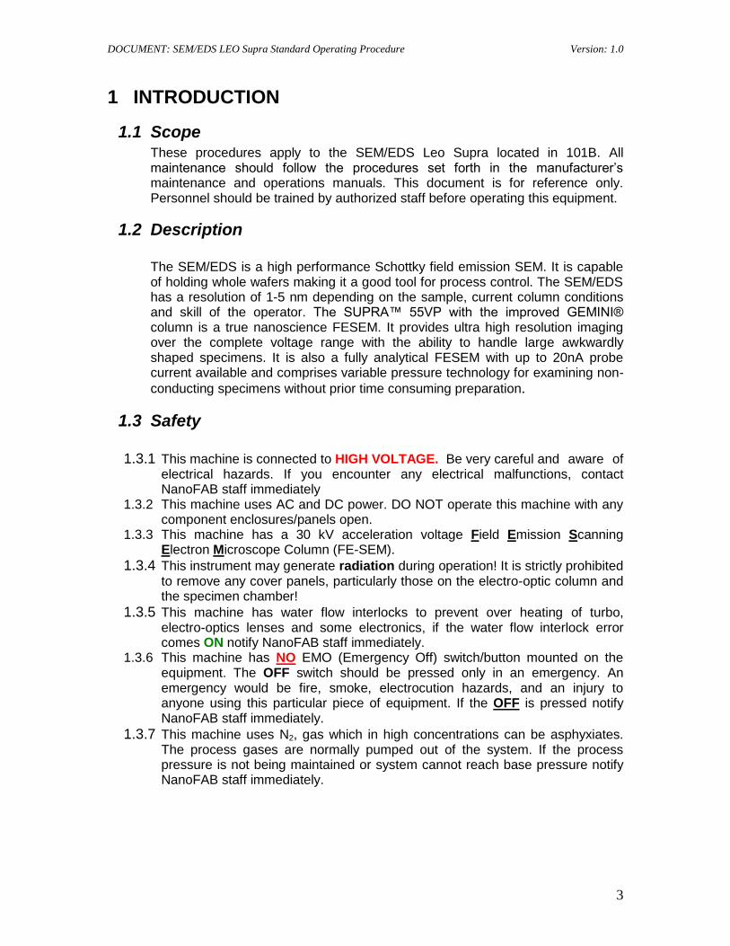
1.1 Scope These procedures apply to the SEM/EDS Leo Supra located in 101B. All maintenance should follow the procedures set forth in the manufacturer‟s maintenance and operations manuals. This document is for reference only. Personnel should be trained by authorized staff before operating this equipment.
1.2 Description
The SEM/EDS is a high performance Schottky field emission SEM. It is capable of holding whole wafers making it a good tool for process control. The SEM/EDS has a resolution of 1-5 nm depending on the sample, current column conditions and skill of the operator. The SUPRA™ 55VP with the improved GEMINI® column is a true nanoscience FESEM. It provides ultra high resolution imaging over the complete voltage range with the ability to handle large awkwardly shaped specimens. It is also a fully analytical FESEM with up to 20nA probe current available and comprises variable pressure technology for examining non-
conducting specimens without prior time consuming preparation.
1.3 Safety
1.3.1 This machine is connected to HIGH VOLTAGE. Be very careful and aware of electrical hazards. If you encounter any electrical malfunctions, contact NanoFAB staff immediately
1.3.2 This machine uses AC and DC power. DO NOT operate this machine with any component enclosures/panels open.
1.3.3 This machine has a 30 kV acceleration voltage Field Emission Scanning Electron Microscope Column (FE-SEM).
1.3.4 This instrument may generate radiation during operation! It is strictly prohibited to remove any cover panels, particularly those on the electro-optic column and the specimen chamber!
1.3.5 This machine has water flow interlocks to prevent over heating of turbo, electro-optics lenses and some electronics, if the water flow interlock error comes ON notify NanoFAB staff immediately.
1.3.6 This machine has NO EMO (Emergency Off) switch/button mounted on the equipment. The OFF switch should be pressed only in an emergency. An emergency would be fire, smoke, electrocution hazards, and an injury to anyone using this particular piece of equipment. If the OFF is pressed notify NanoFAB staff immediately.
1.3.7 This machine uses N2, gas which in high concentrations can be asphyxiates. The process gases are normally pumped out of the system. If the process pressure is not being maintained or system cannot reach base pressure notify NanoFAB staff immediately.
DOCUMENT: SEM/EDS LEO Supra Standard Operating Procedure Version: 1.0
4
2 HARDWARE
2.1 Process Gases: N2
2.2 Gemini FESEM 30kV Max
2.3 EDAX Energy Dispersive X-ray Spectroscopy (EDS) System
2.4 Edwards XDS10 Scroll Dry Pump
2.5 Three Computers- (1) for the LEO SEM and (2) for the EDAX EDS system
3 REQUIREMENTS
3.1 Training
You must be a qualified SEM/EDS Leo Supra 55VP user. To become qualified you must first have submitted an Application to use NanoFAB SEM/EDS/FIB/Ebeam Writer Facilities and been approved. Once approved training will be scheduled and completed. Once completed you will be given a login consisting of your 1000 number as your ID and a password. Then you will be given access to the facilities in 101B or 101C or both as training dictates. There are no exams, completing the training is based on your ability to demonstrate you understand and can operate the equipment to the trainers‟ approval.
3.2 Restrictions
3.2.1 No biological specimens/samples.
3.2.2 Always wear gloves when handling anything that goes in the system.
3.2.3 Only electrically conductive tape may be used.
3.2.4 The EDAX EDS may only be used in Hi-Vac and a WD = 10mm ± .2mm.
3.3 System checks
3.3.1 Check to ensure the system CPU is on and functioning.
3.3.2 Check that the Green ON light is ON, on the front of the SEM, if not contact NanoFAB personnel.
DOCUMENT: SEM/EDS LEO Supra Standard Operating Procedure Version: 1.0
5
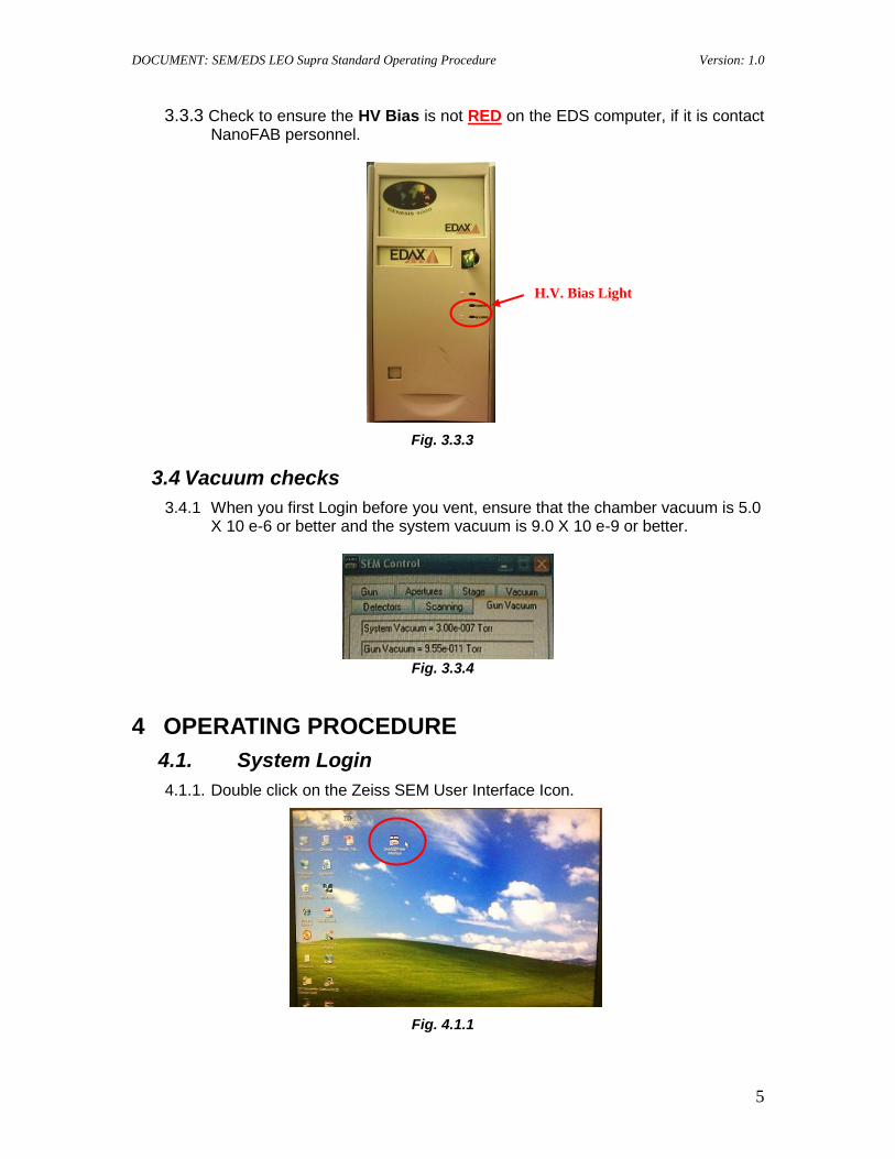
3.3.3 Check to ensure the HV Bias is not RED on the EDS computer, if it is contact NanoFAB personnel.
Fig. 3.3.3
3.4 Vacuum checks
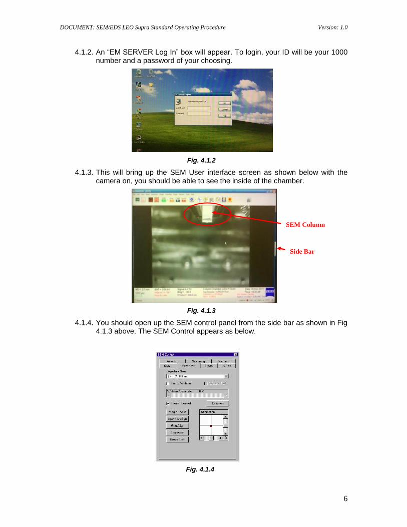
3.4.1 When you first Login before you vent, ensure that the chamber vacuum is 5.0 X 10 e-6 or better and the system vacuum is 9.0 X 10 e-9 or better.
Fig. 3.3.4
4 OPERATING PROCEDURE
4.1. System Login
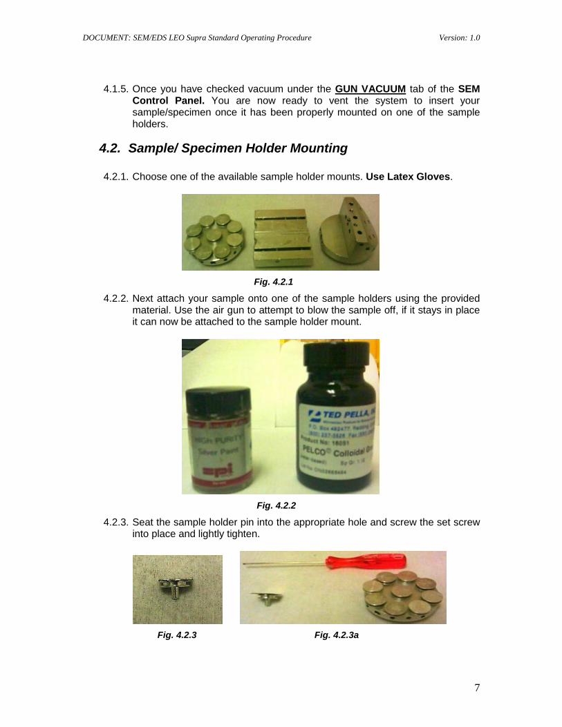
4.1.1. Double click on the Zeiss SEM User Interface Icon.
Fig. 4.1.1
H.V. Bias Light
DOCUMENT: SEM/EDS LEO Supra Standard Operating Procedure Version: 1.0
6
4.1.2. An “EM SERVER Log In” box will appear. To login, your ID will be your 1000 number and a password of your choosing.
Fig. 4.1.2
4.1.3. This will bring up the SEM User interface screen as shown below with the camera on, you should be able to see the inside of the chamber.
Fig. 4.1.3
4.1.4. You should open up the SEM control panel from the side bar as shown in Fig 4.1.3 above. The SEM Control appears as below.
Fig. 4.1.4
SEM Column
Side Bar
DOCUMENT: SEM/EDS LEO Supra Standard Operating Procedure Version: 1.0
7
4.1.5. Once you have checked vacuum under the GUN VACUUM tab of the SEM Control Panel. You are now ready to vent the system to insert your sample/specimen once it has been properly mounted on one of the sample holders.
4.2. Sample/ Specimen Holder Mounting
4.2.1. Choose one of the available sample holder mounts. Use Latex Gloves.
Fig. 4.2.1
4.2.2. Next attach your sample onto one of the sample holders using the provided material. Use the air gun to attempt to blow the sample off, if it stays in place it can now be attached to the sample holder mount.
Fig. 4.2.2
4.2.3. Seat the sample holder pin into the appropriate hole and screw the set screw into place and lightly tighten.
Fig. 4.2.3 Fig. 4.2.3a
DOCUMENT: SEM/EDS LEO Supra Standard Operating Procedure Version: 1.0
8
Fig. 4.2.3b Fig. 4.2.3c
Fig. 4.2.3d
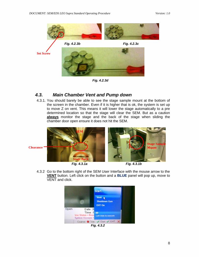
4.3. Main Chamber Vent and Pump down 4.3.1. You should barely be able to see the stage sample mount at the bottom of
the screen in the chamber. Even if it is higher that is ok, the system is set up to move Z on vent. This means it will lower the stage automatically to a pre determined location so that the stage will clear the SEM. But as a caution always monitor the stage and the back of the stage when sliding the chamber door open ensure it does not hit the SEM.
Fig. 4.3.1a Fig. 4.3.1b
4.3.2 Go to the bottom right of the SEM User Interface with the mouse arrow to the VENT button. Left click on the button and a BLUE panel will pop up, move to VENT and click.
Fig. 4.3.2
SEM
Stage Back
Stage Sample
Mount Clearance
Set Screw
DOCUMENT: SEM/EDS LEO Supra Standard Operating Procedure Version: 1.0
9
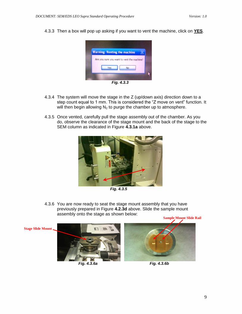
4.3.3 Then a box will pop up asking if you want to vent the machine, click on YES.
Fig. 4.3.3
4.3.4 The system will move the stage in the Z (up/down axis) direction down to a step count equal to 1 mm. This is considered the “Z move on vent” function. It will then begin allowing N2 to purge the chamber up to atmosphere.
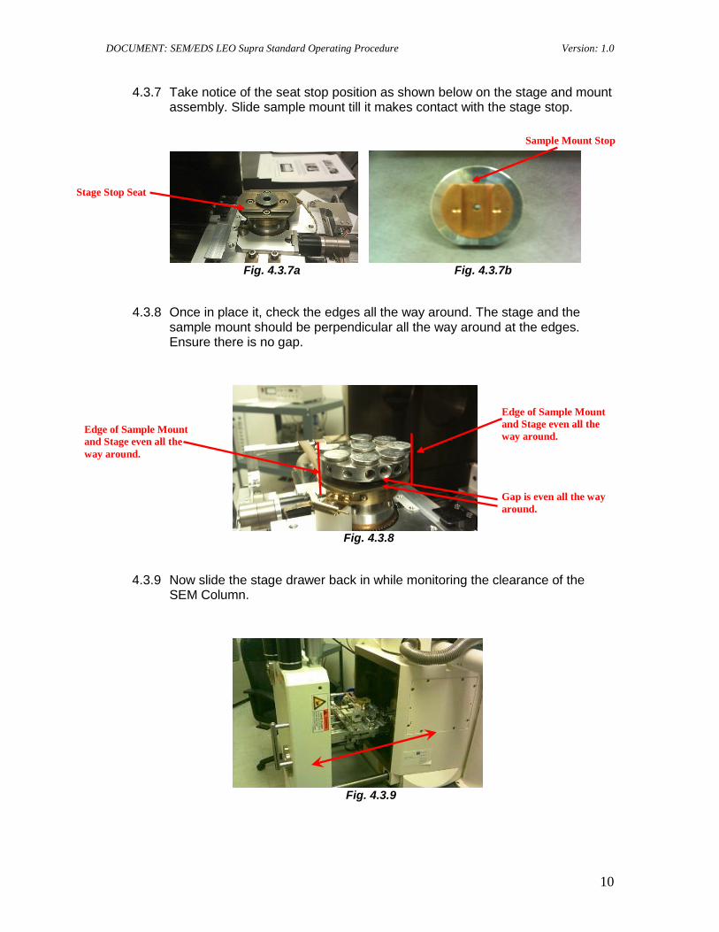
4.3.5 Once vented, carefully pull the stage assembly out of the chamber. As you do, observe the clearance of the stage mount and the back of the stage to the SEM column as indicated in Figure 4.3.1a above.
Fig. 4.3.5
4.3.6 You are now ready to seat the stage mount assembly that you have previously prepared in Figure 4.2.3d above. Slide the sample mount assembly onto the stage as shown below:
Fig. 4.3.6a Fig. 4.3.6b
Stage Slide Mount
Sample Mount Slide Rail
DOCUMENT: SEM/EDS LEO Supra Standard Operating Procedure Version: 1.0
10
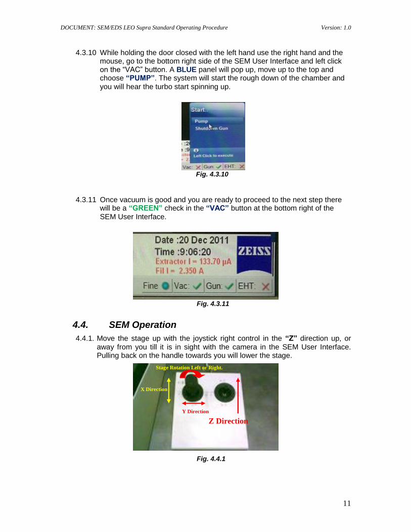
4.3.7 Take notice of the seat stop position as shown below on the stage and mount assembly. Slide sample mount till it makes contact with the stage stop.
Fig. 4.3.7a Fig. 4.3.7b
4.3.8 Once in place it, check the edges all the way around. The stage and the sample mount should be perpendicular all the way around at the edges. Ensure there is no gap.
Fig. 4.3.8
4.3.9 Now slide the stage drawer back in while monitoring the clearance of the SEM Column.
Fig. 4.3.9
Stage Stop Seat
Sample Mount Stop
Edge of Sample Mount
and Stage even all the
way around. Edge of Sample Mount
and Stage even all the
way around.
Gap is even all the way
around.
DOCUMENT: SEM/EDS LEO Supra Standard Operating Procedure Version: 1.0
11
4.3.10 While holding the door closed with the left hand use the right hand and the mouse, go to the bottom right side of the SEM User Interface and left click on the “VAC” button. A BLUE panel will pop up, move up to the top and choose “PUMP”. The system will start the rough down of the chamber and you will hear the turbo start spinning up.
Fig. 4.3.10
4.3.11 Once vacuum is good and you are ready to proceed to the next step there will be a “GREEN” check in the “VAC” button at the bottom right of the SEM User Interface.
Fig. 4.3.11
4.4. SEM Operation
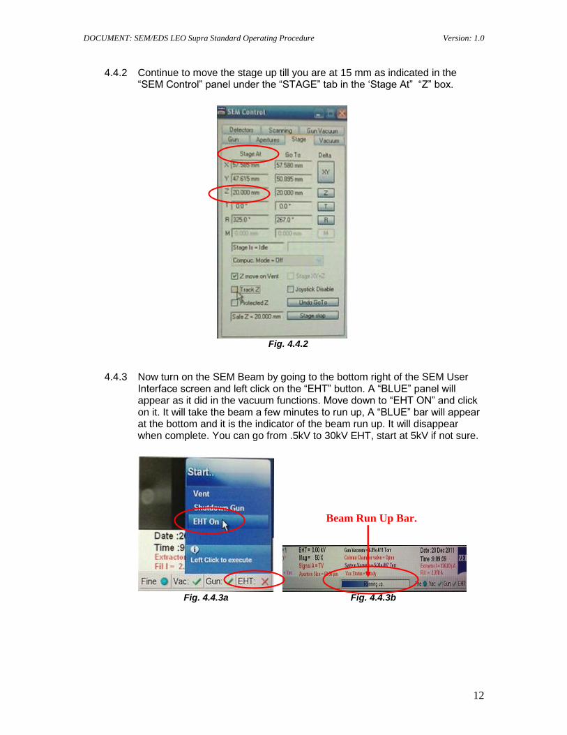
4.4.1. Move the stage up with the joystick right control in the “Z” direction up, or away from you till it is in sight with the camera in the SEM User Interface. Pulling back on the handle towards you will lower the stage.
Fig. 4.4.1
Z Direction
X Direction
Y Direction
Stage Rotation Left or Right.
DOCUMENT: SEM/EDS LEO Supra Standard Operating Procedure Version: 1.0
12
4.4.2 Continue to move the stage up till you are at 15 mm as indicated in the “SEM Control” panel under the “STAGE” tab in the „Stage At” “Z” box.
Fig. 4.4.2
4.4.3 Now turn on the SEM Beam by going to the bottom right of the SEM User Interface screen and left click on the “EHT” button. A “BLUE” panel will appear as it did in the vacuum functions. Move down to “EHT ON” and click on it. It will take the beam a few minutes to run up, A “BLUE” bar will appear at the bottom and it is the indicator of the beam run up. It will disappear when complete. You can go from .5kV to 30kV EHT, start at 5kV if not sure.
Fig. 4.4.3a Fig. 4.4.3b
Beam Run Up Bar.
DOCUMENT: SEM/EDS LEO Supra Standard Operating Procedure Version: 1.0
13
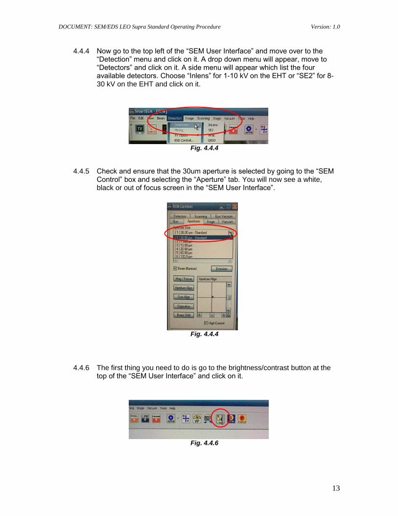
4.4.4 Now go to the top left of the “SEM User Interface” and move over to the “Detection” menu and click on it. A drop down menu will appear, move to “Detectors” and click on it. A side menu will appear which list the four available detectors. Choose “Inlens” for 1-10 kV on the EHT or “SE2” for 8-30 kV on the EHT and click on it.
Fig. 4.4.4
4.4.5 Check and ensure that the 30um aperture is selected by going to the “SEM Control” box and selecting the “Aperture” tab. You will now see a white, black or out of focus screen in the “SEM User Interface”.
Fig. 4.4.4
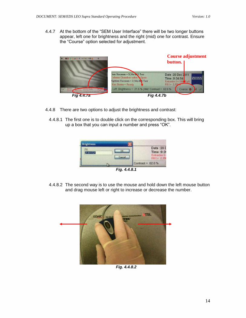
4.4.6 The first thing you need to do is go to the brightness/contrast button at the top of the “SEM User Interface” and click on it.
Fig. 4.4.6
DOCUMENT: SEM/EDS LEO Supra Standard Operating Procedure Version: 1.0
14
4.4.7 At the bottom of the “SEM User Interface” there will be two longer buttons appear, left one for brightness and the right (mid) one for contrast. Ensure the “Course” option selected for adjustment.
Fig 4.4.7a Fig 4.4.7b
4.4.8 There are two options to adjust the brightness and contrast:
4.4.8.1 The first one is to double click on the corresponding box. This will bring up a box that you can input a number and press “OK”.
Fig. 4.4.8.1
4.4.8.2 The second way is to use the mouse and hold down the left mouse button and drag mouse left or right to increase or decrease the number.
Fig. 4.4.8.2
Course adjustment
button.
DOCUMENT: SEM/EDS LEO Supra Standard Operating Procedure Version: 1.0
15
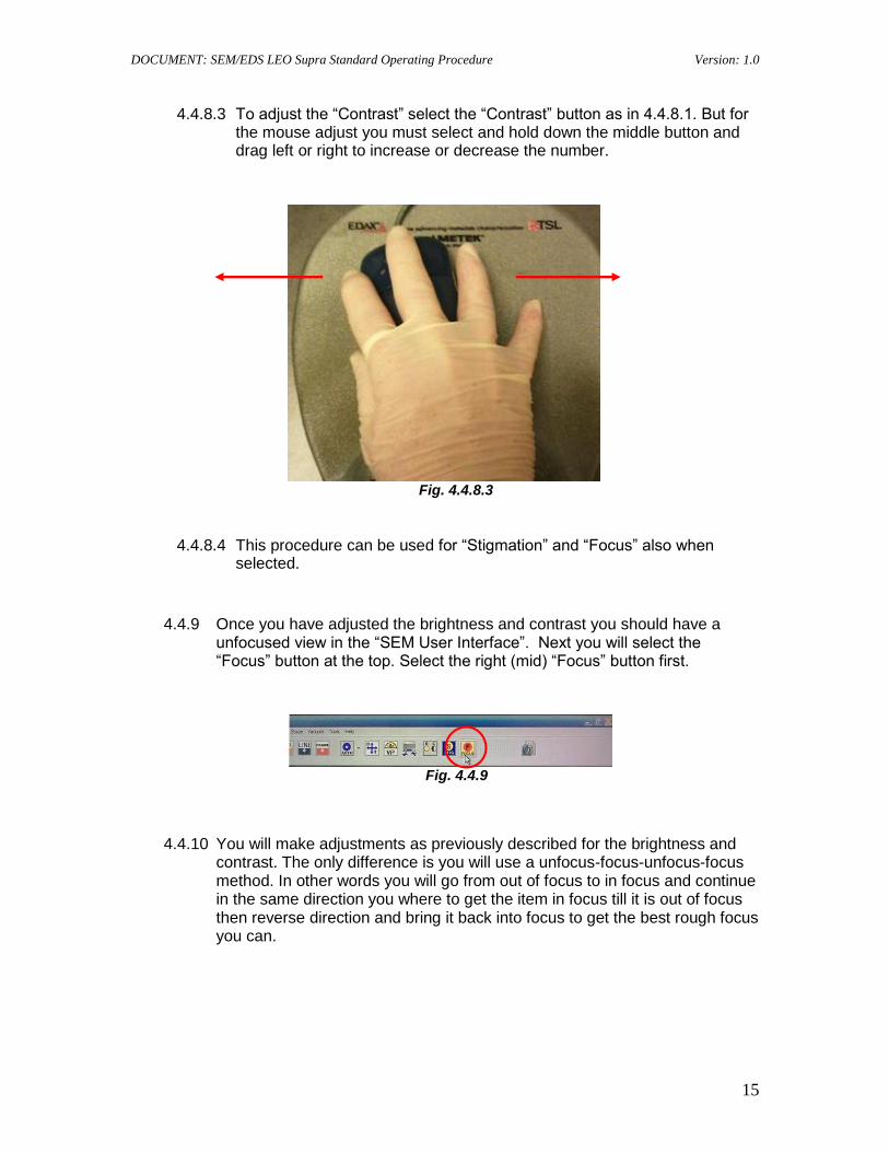
4.4.8.3 To adjust the “Contrast” select the “Contrast” button as in 4.4.8.1. But for the mouse adjust you must select and hold down the middle button and drag left or right to increase or decrease the number.
Fig. 4.4.8.3
4.4.8.4 This procedure can be used for “Stigmation” and “Focus” also when selected.
4.4.9 Once you have adjusted the brightness and contrast you should have a unfocused view in the “SEM User Interface”. Next you will select the “Focus” button at the top. Select the right (mid) “Focus” button first.
Fig. 4.4.9
4.4.10 You will make adjustments as previously described for the brightness and contrast. The only difference is you will use a unfocus-focus-unfocus-focus method. In other words you will go from out of focus to in focus and continue in the same direction you where to get the item in focus till it is out of focus then reverse direction and bring it back into focus to get the best rough focus you can.
DOCUMENT: SEM/EDS LEO Supra Standard Operating Procedure Version: 1.0
16
4.4.11 At this time you will want to go back and set up your stage height. Look at the bottom left of the “SEM User Interface” at the “W.D”. If you will be using the EDAX/EDS you will need to set it up at 10mm. Otherwise you may want to set it up to get the best picture quality based on trial and error. Ensure “TRACK Z” is checked in the “SEM Control” panel and then adjust “Z” (stage up and down position) as indicated in 4.4.1 above.
Fig. 4.4.9a Fig. 4.4.9b
Note: Checking “Track Z” will ensure you maintain the rough focus that you just made!
4.4.12 Once you have adjusted your height you may have to come back at later time to tweak it in. Next you will want to perform a fine focus by locating something extremely small on the surface, enlarging it by clicking on the “Focus” button and choose the left “MAG” (magnification) button or left mouse button and adjust it till it is close by using the previous procedure in 4.4.9 moving the mouse left and/or right.
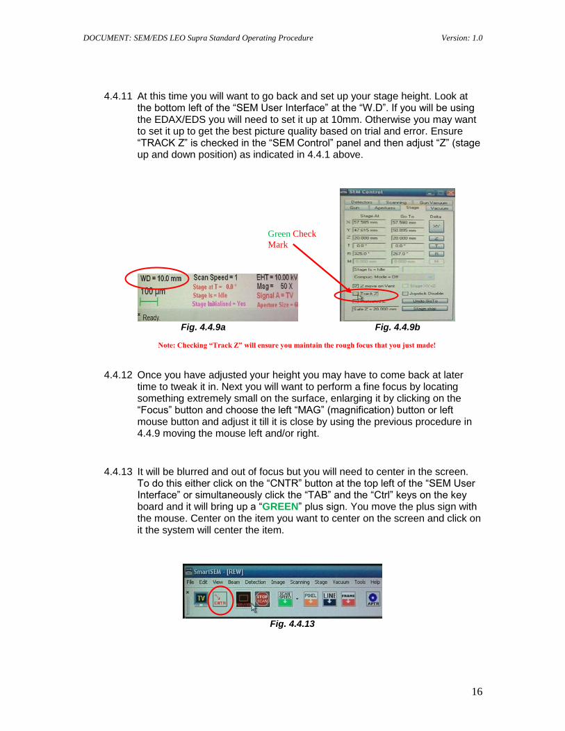
4.4.13 It will be blurred and out of focus but you will need to center in the screen. To do this either click on the “CNTR” button at the top left of the “SEM User Interface” or simultaneously click the “TAB” and the “Ctrl” keys on the key board and it will bring up a “GREEN” plus sign. You move the plus sign with the mouse. Center on the item you want to center on the screen and click on it the system will center the item.
Fig. 4.4.13
Green Check
Mark
DOCUMENT: SEM/EDS LEO Supra Standard Operating Procedure Version: 1.0
17
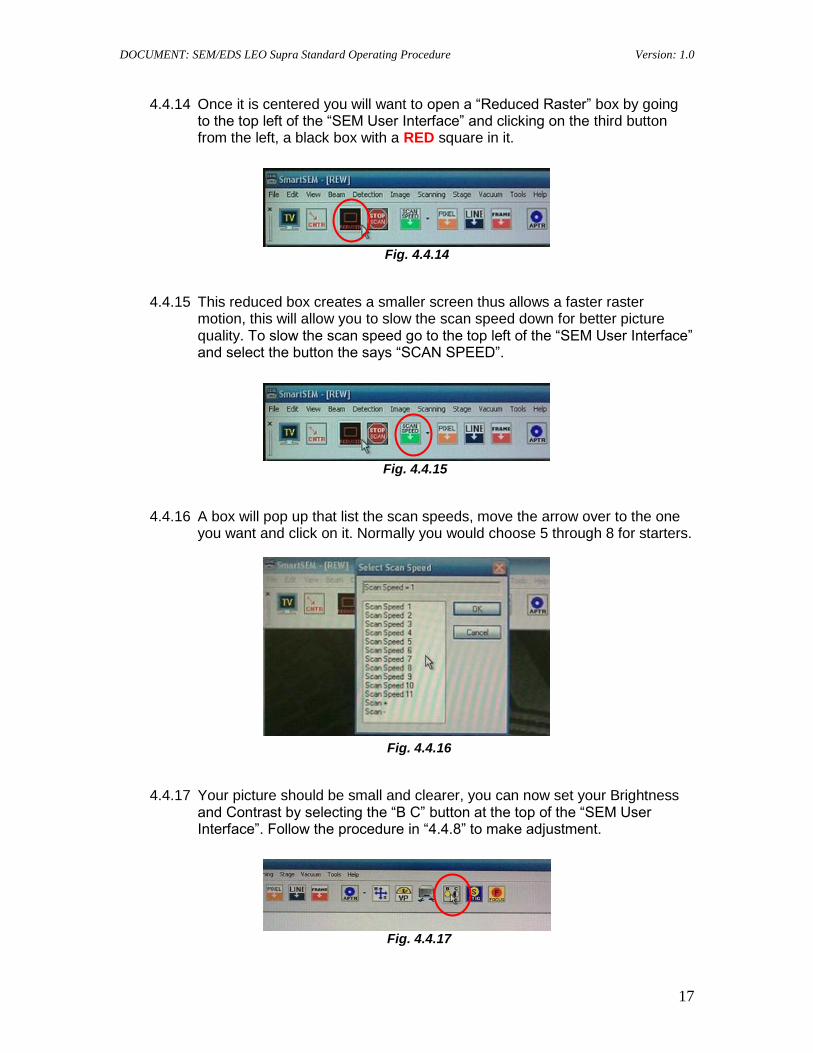
4.4.14 Once it is centered you will want to open a “Reduced Raster” box by going to the top left of the “SEM User Interface” and clicking on the third button from the left, a black box with a RED square in it.
Fig. 4.4.14
4.4.15 This reduced box creates a smaller screen thus allows a faster raster motion, this will allow you to slow the scan speed down for better picture quality. To slow the scan speed go to the top left of the “SEM User Interface” and select the button the says “SCAN SPEED”.
Fig. 4.4.15
4.4.16 A box will pop up that list the scan speeds, move the arrow over to the one you want and click on it. Normally you would choose 5 through 8 for starters.
Fig. 4.4.16
4.4.17 Your picture should be small and clearer, you can now set your Brightness and Contrast by selecting the “B C” button at the top of the “SEM User Interface”. Follow the procedure in “4.4.8” to make adjustment.
Fig. 4.4.17
DOCUMENT: SEM/EDS LEO Supra Standard Operating Procedure Version: 1.0
18
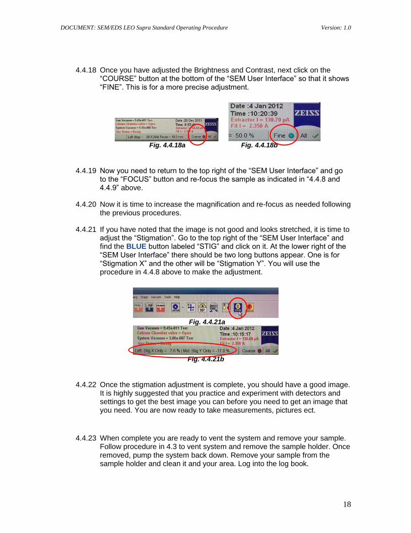
4.4.18 Once you have adjusted the Brightness and Contrast, next click on the “COURSE” button at the bottom of the “SEM User Interface” so that it shows “FINE”. This is for a more precise adjustment.
Fig. 4.4.18a Fig. 4.4.18b
4.4.19 Now you need to return to the top right of the “SEM User Interface” and go to the “FOCUS” button and re-focus the sample as indicated in “4.4.8 and 4.4.9” above.
4.4.20 Now it is time to increase the magnification and re-focus as needed following the previous procedures.
4.4.21 If you have noted that the image is not good and looks stretched, it is time to adjust the “Stigmation”. Go to the top right of the “SEM User Interface” and find the BLUE button labeled “STIG” and click on it. At the lower right of the “SEM User Interface” there should be two long buttons appear. One is for “Stigmation X” and the other will be “Stigmation Y”. You will use the procedure in 4.4.8 above to make the adjustment.
Fig. 4.4.21a
Fig. 4.4.21b
4.4.22 Once the stigmation adjustment is complete, you should have a good image. It is highly suggested that you practice and experiment with detectors and settings to get the best image you can before you need to get an image that you need. You are now ready to take measurements, pictures ect.
4.4.23 When complete you are ready to vent the system and remove your sample. Follow procedure in 4.3 to vent system and remove the sample holder. Once removed, pump the system back down. Remove your sample from the sample holder and clean it and your area. Log into the log book.
DOCUMENT: SEM/EDS LEO Supra Standard Operating Procedure Version: 1.0
19
4.5 Aperture Alignment
4.5.1 If image shifts in reduced window when focusing in and out of a pattern, aperture needs to be aligned.
4.5.2 For that, first set the magnification to 2KX and select reduced window.
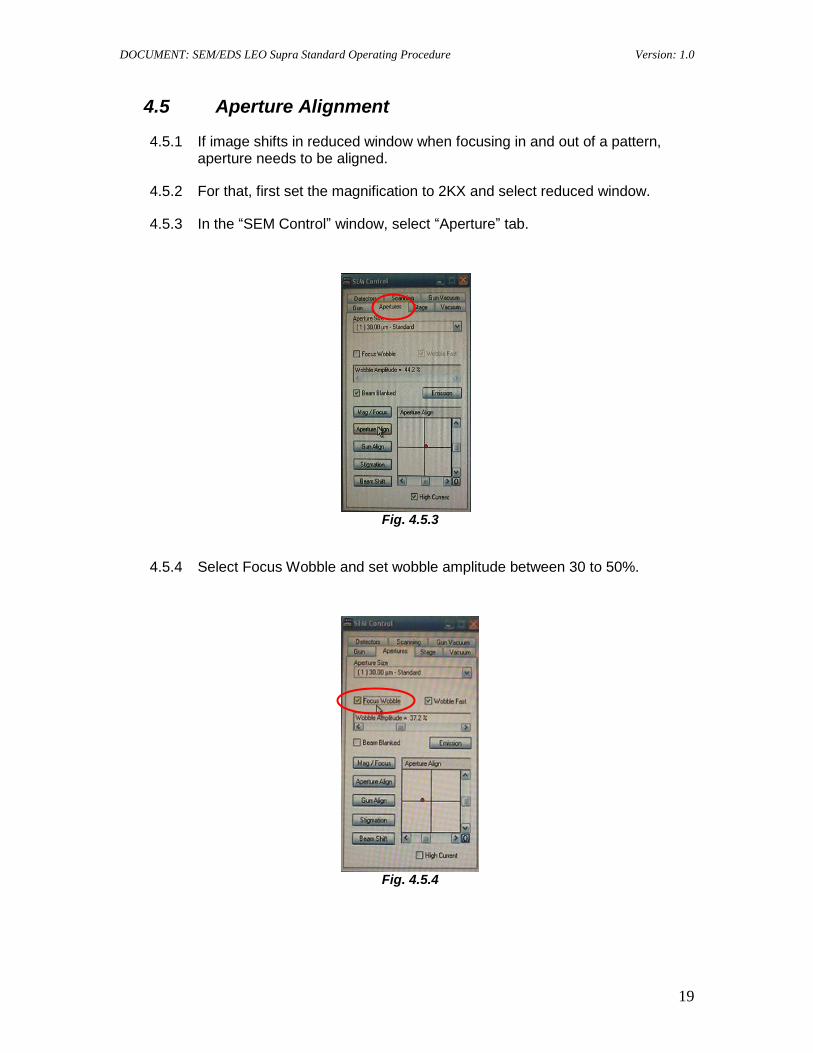
4.5.3 In the “SEM Control” window, select “Aperture” tab.
Fig. 4.5.3
4.5.4 Select Focus Wobble and set wobble amplitude between 30 to 50%.
Fig. 4.5.4
DOCUMENT: SEM/EDS LEO Supra Standard Operating Procedure Version: 1.0
20
4.5.5 Now image will be going in and out of focus in the reduced window and as it does this it will be shifting right/left, up/down, or in any other intermediate direction.
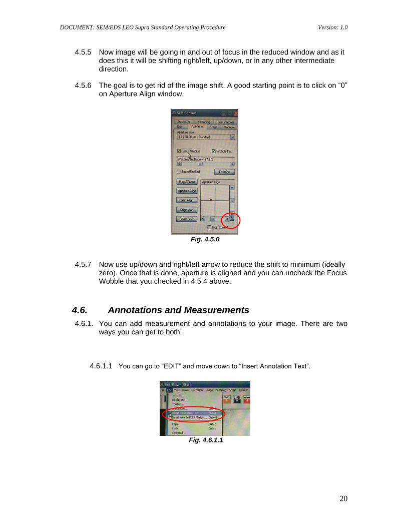
4.5.6 The goal is to get rid of the image shift. A good starting point is to click on “0” on Aperture Align window.
Fig. 4.5.6
4.5.7 Now use up/down and right/left arrow to reduce the shift to minimum (ideally zero). Once that is done, aperture is aligned and you can uncheck the Focus Wobble that you checked in 4.5.4 above.
4.6. Annotations and Measurements
4.6.1. You can add measurement and annotations to your image. There are two ways you can get to both:
4.6.1.1 You can go to “EDIT” and move down to “Insert Annotation Text”.
Fig. 4.6.1.1
DOCUMENT: SEM/EDS LEO Supra Standard Operating Procedure Version: 1.0
21
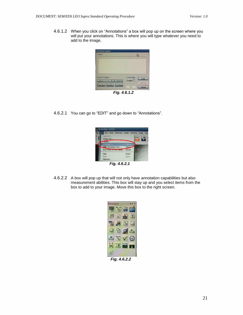
4.6.1.2 When you click on “Annotations” a box will pop up on the screen where you will put your annotations. This is where you will type whatever you need to add to the image.
Fig. 4.6.1.2
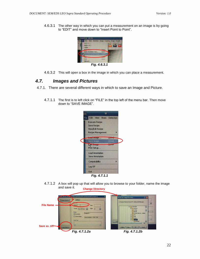
4.6.2.1 You can go to “EDIT” and go down to “Annotations”.
Fig. 4.6.2.1
4.6.2.2 A box will pop up that will not only have annotation capabilities but also measurement abilities. This box will stay up and you select items from the box to add to your image. Move this box to the right screen.
Fig. 4.6.2.2
DOCUMENT: SEM/EDS LEO Supra Standard Operating Procedure Version: 1.0
22
4.6.3.1 The other way in which you can put a measurement on an image is by going to “EDIT” and move down to “Insert Point to Point”.
Fig. 4.6.3.1
4.6.3.2 This will open a box in the image in which you can place a measurement.
4.7. Images and Pictures
4.7.1. There are several different ways in which to save an Image and Picture.
4.7.1.1 The first is to left click on “FILE” in the top left of the menu bar. Then move down to “SAVE IMAGE”.
Fig. 4.7.1.1
4.7.1.2 A box will pop up that will allow you to browse to your folder, name the image and save it.
Fig. 4.7.1.2a Fig. 4.7.1.2b
Change Directory
File Name
Save as .tiff
DOCUMENT: SEM/EDS LEO Supra Standard Operating Procedure Version: 1.0
23
4.7.2.1 The other way is to right click on the mouse with the arrow over the image and a box will appear. Move down the box to “SEND TO” and highlight with the arrow and another drop down box will appear.
Fig. 4.7.2.1
4.7.2.2 As you can see here you may save the image as a .tiff, .bmp or a .jpg image. Move your arrow over whichever one you would like to save it as then left click on the mouse and a similar box will appear as in 4.7.1.2a. The only difference is when you save it the save button will indicate which one you are saving as.
Fig. 4.7.2.2a Fig. 4.7.2.2b Fig. 4.7.2.2c
5 EDAX/EDS System
5.1 Operation
5.1.1 Image the sample using SEM as previously described and select the area where you want to do EDS.
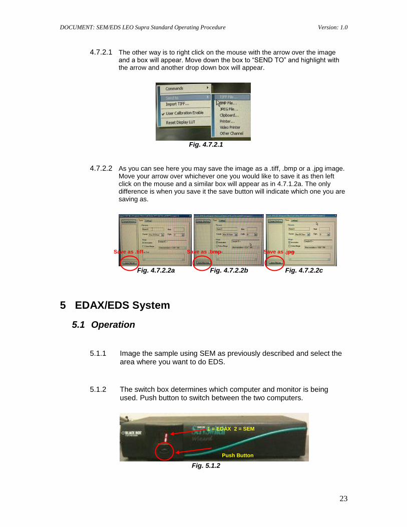
5.1.2 The switch box determines which computer and monitor is being used. Push button to switch between the two computers.
Fig. 5.1.2
Save as .tiff Save as .bmp Save as .jpg
1 = EDAX 2 = SEM
Push Button
DOCUMENT: SEM/EDS LEO Supra Standard Operating Procedure Version: 1.0
24
5.1.3 Next go to the EDAX/EDS Monitor and click on the Genesis Icon to get the spectrum software to boot up. Note: If EDAX/EDS system has been idle
for more than 1 day, it is a good idea to soft boot the computer by doing a restart of the system.
Fig. 5.1.3
5.1.4 To get the maximum EDS signal you should be working at about WD = 10 mm. Also, as a general guideline, EHT value is chosen to be two
times as large as either the highest K, L or M energy value of the peak you are interested in the spectrum to a maximum of 30kV.
Fig. 5.1.4
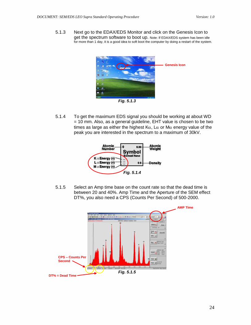
5.1.5 Select an Amp time base on the count rate so that the dead time is between 20 and 40%. Amp Time and the Aperture of the SEM effect DT%, you also need a CPS (Counts Per Second) of 500-2000.
Fig. 5.1.5
AMP Time
DT% = Dead Time
Genesis Icon
CPS – Counts Per Second
DOCUMENT: SEM/EDS LEO Supra Standard Operating Procedure Version: 1.0
25
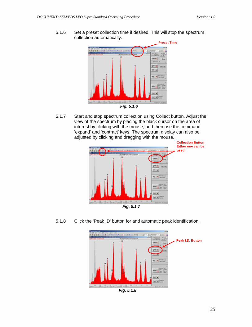
5.1.6 Set a preset collection time if desired. This will stop the spectrum collection automatically.
Fig. 5.1.6
5.1.7 Start and stop spectrum collection using Collect button. Adjust the view of the spectrum by placing the black cursor on the area of interest by clicking with the mouse, and then use the command 'expand' and 'contract' keys. The spectrum display can also be adjusted by clicking and dragging with the mouse.
Fig. 5.1.7
5.1.8 Click the 'Peak ID' button for and automatic peak identification.
Fig. 5.1.8
Preset Time
Collection Button Either one can be
used.
Peak I.D. Button
DOCUMENT: SEM/EDS LEO Supra Standard Operating Procedure Version: 1.0
26
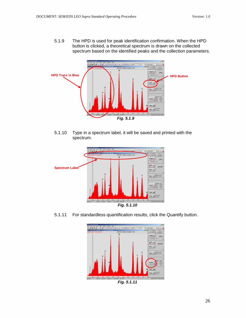
5.1.9 The HPD is used for peak identification confirmation. When the HPD button is clicked, a theoretical spectrum is drawn on the collected spectrum based on the identified peaks and the collection parameters.
Fig. 5.1.9
5.1.10 Type in a spectrum label, it will be saved and printed with the spectrum.
Fig. 5.1.10
5.1.11 For standardless quantification results, click the Quantify button.
Fig. 5.1.11
HPD Button HPD Trace in Blue
Spectrum Label
DOCUMENT: SEM/EDS LEO Supra Standard Operating Procedure Version: 1.0
27
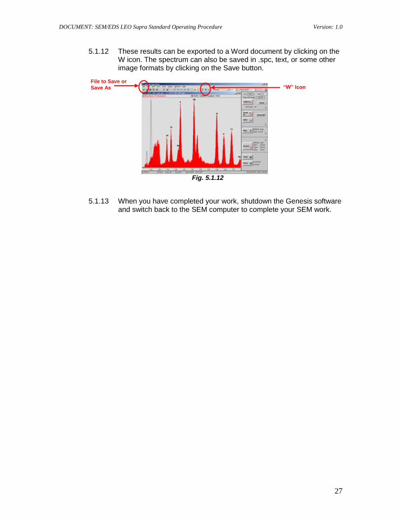
5.1.12 These results can be exported to a Word document by clicking on the W icon. The spectrum can also be saved in .spc, text, or some other image formats by clicking on the Save button.
Fig. 5.1.12
5.1.13 When you have completed your work, shutdown the Genesis software and switch back to the SEM computer to complete your SEM work.
“W” Icon File to Save or
Save As