self-operated temperature regulators type 2213 safety ... · devices with a ce marking have an eu...
TRANSCRIPT

Mounting and Operating Instructions
EB 2043 EN
Tran
slatio
n of
orig
inal
instr
uctio
ns
Edition January 2018
Self-operated Temperature Regulators
Type 2213 Safety Temperature Monitor (STM)

2 EB 2043 EN
Note on these mounting and operating instructions
These mounting and operating instructions assist you in mounting and operating the device safely. The instructions are binding for handling SAMSON devices.
Î For the safe and proper use of these instructions, read them carefully and keep them for later reference.
Î If you have any questions about these instructions, contact SAMSON‘s After-sales Service Department ([email protected]).
The mounting and operating instructions for the devices are included in the scope of delivery. The latest documentation is available on our website at www.samson.de > Service & Support > Downloads > Documentation.
Definition of signal words
Hazardous situations which, if not avoided, will result in death or serious injury
Hazardous situations which, if not avoided, could result in death or serious injury
Property damage message or malfunction
Additional information
Recommended action
DANGER!
WARNING!
NOTICE!
Note
Tip

Contents
EB 2043 EN 3
1 Safety instructions and measures ...................................................................41.1 Notes on possible severe personal injury .........................................................61.2 Notes on possible personal injury ...................................................................71.3 Notes on possible property damage ................................................................82 Markings on the device .................................................................................92.1 Material number ..........................................................................................103 Design and principle of operation ................................................................103.1 Technical data .............................................................................................123.2 Process medium and scope of application ......................................................124 Measures for preparation ............................................................................164.1 Unpacking ..................................................................................................164.2 Transporting and lifting ................................................................................164.3 Storage .......................................................................................................174.4 Preparation for installation ............................................................................175 Mounting and start-up .................................................................................185.1 Mounting the safety temperature monitor onto the valve ..................................185.2 Additionalfittings .........................................................................................185.3 Temperature sensor and capillary tube ...........................................................195.4 Electric signal transmitter ..............................................................................205.4.1 Retrofittingandadjustingasignaltransmitter .................................................205.5 Combinationwithdifferentialpressureandflowregulators ..............................225.6 Start-up .......................................................................................................225.6.1 Gases and liquids ........................................................................................235.6.2 Steam .........................................................................................................236 Operation ...................................................................................................236.1 Adjusting the limit temperature ......................................................................236.2 Sensor failure ..............................................................................................236.3 Correcting the limit value dial........................................................................246.4 Fine adjustment of the limit temperature .........................................................247 Servicing.....................................................................................................257.1 Preparation for return shipment .....................................................................268 Malfunctions ...............................................................................................269 Decommissioning and disassembly ..............................................................289.1 Decommissioning .........................................................................................289.2 Disposal ......................................................................................................2910 Appendix ....................................................................................................2910.1 After-sales service and spare parts ................................................................2910.2 Certificates ..................................................................................................29

4 EB 2043 EN
Safety instructions and measures
1 Safety instructions and measuresIntended useTheType 2213SafetyTemperatureMonitor(STM)withvalveisdesignedfortemperaturemonitoring and control of the energy supply to heat generators (e.g. heat exchangers) by closingthevalve.Theconnectionofanadditionalcontrolthermostat(e.g.Type 2231)con-verts the safety temperature monitor (STM) into a temperature regulator with safety tempera-ture monitor (TR/STM).
Thedevicesaredesignedtooperateunderexactlydefinedconditions(e.g.operatingpres-sure, process medium, temperature). Therefore, operators must ensure that the devices are onlyusedinoperatingconditionsthatmeetthespecificationsusedforsizingthedevicesatthe ordering stage. In case operators intend to use the devices in other applications or condi-tionsthanspecified,contactSAMSON.
SAMSON does not assume any liability for damage resulting from the failure to use the de-vice for its intended purpose or for damage caused by external forces or any other external factors.
Î Refertothetechnicaldataandnameplateforlimitsandfieldsofapplicationaswellaspossible uses.
Reasonably foreseeable misuseThedevicesarenotsuitableforuseoutsidethelimitsdefinedduringsizingandbythetechni-cal data. Furthermore, the following activities do not comply with the intended use: − Use of non-original spare parts − Performing service and repair work not described in these instructions
Qualifications of operating personnelThe devices must be mounted, started up, serviced and repaired by fully trained and quali-fiedpersonnelonly;theacceptedindustrycodesandpracticesaretobeobserved.Accord-ing to these mounting and operating instructions, trained personnel refers to individuals who areabletojudgetheworktheyareassignedtoandrecognizepossiblehazardsduetotheirspecializedtraining,theirknowledgeandexperienceaswellastheirknowledgeoftheappli-cable standards.
Personal protective equipmentWerecommendcheckingthehazardsposedbytheprocessmediumbeingused(e.g.u GESTIS(CLP)hazardoussubstancedatabase).

EB 2043 EN 5
Safety instructions and measures
Î Provide protective equipment (e.g. safety gloves, eye protection) appropriate for the pro-cess medium used.
Î Wear hearing protection when working near the valve.
Î Check with the plant operator for details on further protective equipment.
Revisions and other modificationsRevisions,conversionsorothermodificationsoftheproductarenotauthorizedbySAMSON.Theyareperformedattheuser'sownriskandmayleadtosafetyhazards,forexample.Fur-thermore, the product may no longer meet the requirements for its intended use.
Warning against residual hazardsTo avoid personal injury or property damage, plant operators and operating personnel must preventhazardsthatcouldbecausedinthedevicebytheprocessmedium,theoperatingpressureorbymovingpartsbytakingappropriateprecautions.Theymustobserveallhaz-ard statements, warning and caution notes in these mounting and operating instructions, es-pecially for installation, start-up and service work.Wealsorecommendcheckingthehazardsposedbytheprocessmediumbeingused(e.g.u GESTIS(CLP)hazardoussubstancedatabase).
Î Observesafetymeasuresforhandlingthedeviceaswellasfirepreventionandexplosionprotection measures.
Responsibilities of the operatorThe operator is responsible for proper operation and compliance with the safety regulations. Operators are obliged to provide these mounting and operating instructions as well as the referenced documents to the operating personnel and to instruct them in proper operation. Furthermore, the operator must ensure that operating personnel or third persons are not ex-posed to any danger.
Responsibilities of operating personnelOperating personnel must read and understand these mounting and operating instructions as wellasthereferenceddocumentsandobservethespecifiedhazardstatements,warningsand caution notes. Furthermore, the operating personnel must be familiar with the applicable health, safety and accident prevention regulations and comply with them.

6 EB 2043 EN
Safety instructions and measures
Referenced standards and regulationsThe devices comply with the requirements of the European Pressure Equipment Directive 2014/68/EU. Devices with a CE marking have an EU declaration of conformity, which in-cludes information about the applied conformity assessment procedure. This EU declaration ofconformityisincludedintheAppendixoftheseinstructions(seesection 10.2).
Non-electric valve versions whose bodies are not lined with an insulating material coating do not have their own potential ignition source according to the risk assessment stipulated in EN 13463-1: 2009,section 5.2,evenintherareincidentofanoperatingfault.Therefore,such valve versions do not fall within the scope of Directive 2014/34/EU.
Î Forconnectiontotheequipotentialbondingsystem,observetherequirementsspecifiedinsection6.4ofEN 60079-14(VDE 0165Part1).
Referenced documentationThe following documents apply in addition to these mounting and operating instructions:
− Mounting and operating instructions for valves, e.g. u EB 2111/2112/2113/2121/2123
− Mounting and operating instructions for the control thermostats, e.g. u EB 2231 − Mounting and operating instructions for the safety temperature limiter, e.g. u EB 2046
1.1 Notes on possible severe personal injuryDANGER!
Risk of personal injury due to process medium escaping under pressure.While removing the control thermostat/safety temperature monitor (STM)/safety tem-peraturelimiter(STL)fromthevalve,thesealed-offvalveisopened.Residualprocessmedium will escape and, depending on its properties, may lead to personal injury, e.g. (chemical) burns.
Î Depressurizetheplant. Î First start up the regulator after mounting all parts. Î Wear protective clothing, safety gloves and eyewear.

EB 2043 EN 7
Safety instructions and measures
DANGER!
Risk of bursting in pressure equipment.Valvesandpipelinesarepressureequipment.Improperopeningcanleadtovalvecomponents bursting.
Î Beforestartinganyworkonthevalve,depressurizeallplantsectionsconcernedaswell as the valve.
Î Drain the process medium from all the plant sections concerned as well as the valve.
Î Wear personal protective equipment.
1.2 Notes on possible personal injuryWARNING!
Risk of personal injury due to residual process medium in the valve and safety tem-perature monitor.While working on the valve or safety temperature monitor, residual process medium can escape and, depending on its properties, may lead to personal injury, e.g. (chem-ical) burns.
Î If possible, drain the process medium from all the plant sections concerned and the valve.
Î Wear protective clothing, safety gloves and eyewear.
Risk of burn injuries due to hot or cold components and pipelines.Depending on the process medium, valve components and pipelines may get very hot or cold and cause burn injuries.
Î Allow components and pipelines to cool down or heat up. Î Wear protective clothing and safety gloves.
Damage to health relating to the REACH regulation.If a SAMSON device contains a substance which is listed as being a substance of very high concern on the candidate list of the REACH regulation, this circumstance is indi-cated on the SAMSON delivery note.
Î Information on safe use of the part affected, see u http://www.samson.de/reach-en.html.

8 EB 2043 EN
Safety instructions and measures
1.3 Notes on possible property damageNOTICE!
Risk of valve damage due to unsuitable medium properties.Thevalveisdesignedforaprocessmediumwithdefinedproperties.
Î Onlyusetheprocessmediumspecifiedforsizing.
Irreparable regulator damage caused by the regulator components being taken apart.The safety temperature monitor is an inseparable hydraulic unit consisting of a safety thermostat, capillary tube and temperature sensor. If these components are dismantled (e.g. removal of the capillary tube), the regulator will be irreparably damaged and will nolongerbeabletofulfillitsmonitoringandcontroltask.
Î Do not dismantle the regulator. Î Only perform allowed activities on the regulator. Î Contact SAMSON's After-sales Service department before replacing spare parts.
Risk of valve damage due to contamination (e.g. solid particles) in the pipeline.The plant operator is responsible for cleaning the pipelines in the plant.
Î Flush the pipelines before start-up. Î Observe the maximum permissible pressure for valve and plant.
Risk of damage to the valve or safety temperature monitor due to excessively high or low tightening torques.The connection between valve and safety temperature monitor must be tightened with a certain tightening torque.
Excessively tightened torques lead to parts wearing out quicker. Parts that are too loose may cause leakage.
Î Observethespecifiedtighteningtorques.

EB 2043 EN 9
Markings on the device
2 Markings on the deviceSpecifications on the dial housing SAMSON x
Gr. DNMade in Germany
bar°C
bar°C
1 2 35
6 7 8
4
1 Type2 ConfigurationID3 Date4 Limitvaluerangein°Cand°F
5 Register number (type test accord-ingtoDIN EN 14597)
6 Size7 Valvesize8 Pressure or temperature range
Specifications on the valve
DIN flange version1 Type2 ConfigurationID3 Index4 Order number/date5 KVScoefficient8 NominalsizeDN9 Nominal pressure PN10 Perm.differentialpressureΔpinbar11 Perm.temperaturein°C12 Bodymaterial
ANSI flange version1 Type2 ConfigurationID3 Index4 Order number/date5 Valvesize8 Perm.differentialpressurepΔinpsi9 Perm.temperaturein°F
10 Bodymaterial11 CVcoefficient12 Pressure rating (Class)
SAMSONDNbar
Made in Germany°CTbar∆pPN
KvsNo129 10 118
54132DIN
No
∆pMade in Germany
SizeSAMSONpsiN psi T °F Cv Cl98 10 11 12
54132ANSI
Fig. 1: Nameplates

10 EB 2043 EN
Design and principle of operation
3 Design and principle of oper-ation
See Fig. 2.The safety temperature monitor (STM) oper-ates according to the liquid expansion prin-ciple. The temperature sensor (12), capillary tube(9)andoperatingelement(8)arefilledwith an expansion liquid.
The temperature-dependent change in vol-ume of the liquid in the bulb sensor (12) causes the piston in the operating element (8) to move. As a result, the pin of the oper-ating element (7) moves the plug stem (5) with the plug (3). The temperature limit can be adjusted by a key (10). This limit value is indicated on the dial (11).
The safety temperature monitor closes the valve when the temperature reaches the ad-justed temperature limit. The safety tempera-ture monitor resets itself automatically when the temperature has fallen to a value of ap-prox.5 Kbelowtheadjustedlimit.
Fail-safe positionThe spring mechanism in the operating ele-ment is released when the capillary tube breaks or when there is a leak in the sensor. It moves the plug stem (5) with the plug (3) over the pin (7) and closes and locks the valve.
The adjusted limit temperature must have a minimum temperature difference of 15 K to the set point of the temperature regulator.
Note
2.1 Material numberSpecifyingtheconfigurationID,youcancon-tactustofindoutwhichmaterialisused.TheconfigurationIDisspecifiedonthename-plate(2and3;configurationIDanddeviceindex). For more details on the nameplate, seeFig. 1.

EB 2043 EN 11
Design and principle of operation
Fig. 2: Type 2422/2213 Safety Temperature Monitor (STM) with Type 2422 Globe Valve
1 Valvebody2 Seat (exchangeable)3 Plug5 Plug stem6 Couplingnut(150 Nmtighteningtorque)7 Connecting piece with pin of the operating
element8 Operating element with spring mechanism8.1 Electric signal transmitter
8.2 Signal pin8.3 Travel indicator9 Capillary tube10 Key to adjust limit value11 Limitvaluedial12 Temperature sensor (bulb sensor with ther-
mowell)13 Leadingscrew(oncustomerrequest)14 Dial housing
1413
10
11
128
9
8.2
7
6
5
3
2
1
8.1
8.3

12 EB 2043 EN
Design and principle of operation
3.1 Technical data
3.2 Process medium and scope of application
Safety temperature monitoring of the energy supply for heat generators or heat exchang-ers by closing the valve.
For limit signals from –10 to 120 °C (14 to 248 °F)·ValvesDN 15 to 150 (NPS ½ to 10) · PN 16 to 40 (Class 150 to 300) · Max. 350 °C (660 °C)
TheType 2213SafetyTemperatureMonitor(STM) with a valve operates without auxilia-ry energy and is designed for extended safe-tyaccordingtoDIN EN 14597.Thevalveisclosed by a spring mechanism when the tem-perature reaches the adjusted limit, when the capillary tube breaks or when leakage oc-curs in the sensor system. The devices are automatically reset and put back into opera-tion after the temperature has fallen below the limit and the fault has been remedied.
When the safety temperature monitor is com-binedwithaType 2231to2235ControlThermostat, make sure that there is a mini-mumdifferenceofapproximately15 Kbe-tween the adjusted limit temperature of the safety temperature monitor and the set point temperature of the control thermostat.
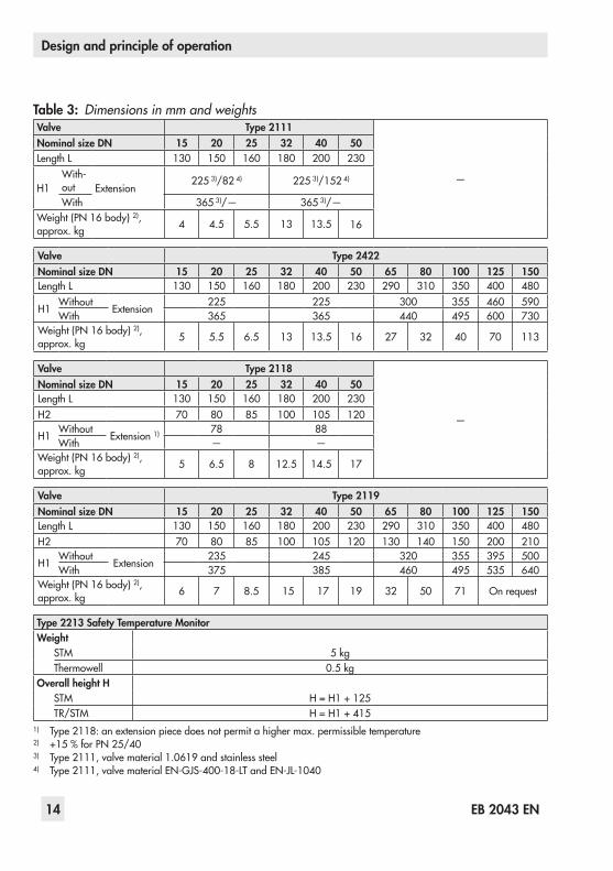
Dimensions and weightsFig. 3providesasummaryofthedimensionsandweightsoftheType 2213SafetyTem-peratureMonitoraswellastheTypes 2111,2422,2118and2119Valves.Thelengthsand heights in the dimension diagrams are shownonpage 15 onwards.
Typetesting
The safety temperature monitor is tested by theGermanTechnicalInspectorate(TÜV)ac-cordingtoDIN EN 14597underthetypedesignation 2213. The registration number is available on request.
Further details and technical data of the valves and control thermostats are listed in the following mounting and operating in-structions: − Mounting and operating instructions for valves, e.g. u EB 2111/2112/2113/2121/2123 − Mounting and operating instructions for the control thermostats, e.g. u EB 2231 − Mounting and operating instructions for the safety temperature limiter, e.g. u EB 2046
Note

EB 2043 EN 13
Design and principle of operation
Table 1: Technical data · Type 2213 Safety Temperature Monitor (STM)
Type 2213 Safety Temperature Monitor
Adjustment ranges of limit temperature –10to+90 °C · +20to+120 °C (14to194 °F · 68to248 °F)
Permissible ambient temperature range at the limit value adjuster
–40to+80 °C (–40to+176 °F)
Permissible temperature at sensor 100 Kabovetheadjustedlimit
Permissible pressure at the sensor WithG 1thermowell 40 bar(580 psi)
Without thermowell 6 bar(87 psi)
Capillary tube length 1) 5 m · 10 m 2) (197 in · 394 in 2))
Compliance ·1) Special version also in plastic-coated copper2) NottestedaccordingtoDIN EN 14597
Table 2: Technical data · Types 2111, 2422, 2118 and 2119 Valves
Valve Type 2111, Type 2422, Type 2118 and Type 2119
Valvesize DN 15 20 25 32 40 50 65 80 100 125 150 200 250
Type 2111 u T 2111 —
Type 2422 u T 2121
Type 2118 u T 2131 —
Type 2119 u T 2133 —
Nominal pressure PN 16to40
Compliance ·
Valvesize NPS ½ ¾ 1 1½ 2 2½ 3 4 6 8 10
Type 2111 u T 2115 ——
Type 2422 u T 2025
Type 2119 u T 2134 —
Pressure rating Class 150to300
Compliance ·
14 EB 2043 EN
Design and principle of operation
Table 3: Dimensions in mm and weightsValve Type 2111
—
Nominal size DN 15 20 25 32 40 50LengthL 130 150 160 180 200 230
H1With-out Extension
225 3)/82 4) 225 3)/152 4)
With 365 3)/— 365 3)/—Weight(PN 16body)2), approx. kg 4 4.5 5.5 13 13.5 16
Valve Type 2422Nominal size DN 15 20 25 32 40 50 65 80 100 125 150LengthL 130 150 160 180 200 230 290 310 350 400 480
H1Without
Extension225 225 300 355 460 590
With 365 365 440 495 600 730Weight(PN 16body)2), approx. kg 5 5.5 6.5 13 13.5 16 27 32 40 70 113
Valve Type 2118
—
Nominal size DN 15 20 25 32 40 50LengthL 130 150 160 180 200 230H2 70 80 85 100 105 120
H1Without
Extension 1) 78 88With — —
Weight(PN 16body)2), approx. kg 5 6.5 8 12.5 14.5 17
Valve Type 2119Nominal size DN 15 20 25 32 40 50 65 80 100 125 150LengthL 130 150 160 180 200 230 290 310 350 400 480H2 70 80 85 100 105 120 130 140 150 200 210
H1Without
Extension235 245 320 355 395 500
With 375 385 460 495 535 640Weight(PN 16body)2), approx. kg 6 7 8.5 15 17 19 32 50 71 On request
Type 2213 Safety Temperature MonitorWeight
STM 5 kgThermowell 0.5 kg
Overall height HSTM H = H1 + 125TR/STM H = H1 + 415
1) Type 2118:anextensionpiecedoesnotpermitahighermax.permissibletemperature2) +15 %forPN 25/403) Type 2111,valvematerial1.0619andstainlesssteel4) Type 2111,valvematerialEN-GJS-400-18-LTandEN-JL-1040

EB 2043 EN 15
Design and principle of operation
G1G1
Ø25
290
310
H
L
H1SW 46
SW 41
199
128
Fig. 3: Dimension diagrams of Type 2111/2213 · Type 2422/2213 · Type 2118/2213 · Type 2119/2213
G1
Ø28
325
140
G1
G1
SW 36
L
H1H
G1
G1H
H2
L
H1
H1
H
L
H2
G1
Type 2422 Valve andType 2111Valve(1.0619,stainlesssteel)
Type 2111 Valve(EN-JS1049,EN-JL1040)
Type 2119 ValveType 2118 Valve
Extension piece(approx.0.5 kg)Addapprox.140 mmtotheoverallheightH1 or H when an extension piece is used.
ThermowellforType 2213With threaded connection G 1forPN 40
All dimensions in mm

16 EB 2043 EN
Measures for preparation
4 Measures for preparationAfter receiving the shipment, proceed as fol-lows:
1. Check the scope of delivery. Compare the shipment received with the delivery note.
2. Check the shipment for transportation damage. Report any damage to SAMSON and the forwarding agent (refer to delivery note).
4.1 Unpacking
Do not remove the packaging until immedi-ately before mounting it onto the valve.
Proceed as follows to lift and mount the de-vice:
1. Remove the packaging from the device.
2. Dispose of the packaging in accordance with the valid regulations.
Note
4.2 Transporting and liftingDue to the low service weight, lifting equip-ment is not required to lift and transport the safety temperature monitor (e.g. to mount it onto the valve).
Transport instructions − Protectthedeviceagainstexternalinflu-
ences (e.g. impact). − Protect the device against moisture and
dirt. − Do not damage the corrosion protection
(paint, surface coatings). Repair any damage immediately.
− Observe the permissible ambient tem-peratures(seesection 3.2).

EB 2043 EN 17
Measures for preparation
4.3 Storage
Risk of device damage due to improper stor-age. − Observe storage instructions. − Avoid long storage times. − Contact SAMSON in case of different stor-age conditions or long storage periods.
We recommend regularly checking the de-vice and the prevailing storage conditions during long storage periods.
Storage instructions − Protect the safety temperature monitor againstexternalinfluences(e.g.impact).
− Do not damage the corrosion protection (paint, surface coatings). Repair any damage immediately.
− Protect the device against moisture and dirt. Store it at a relative humidity of less than75 %.Indampspaces,preventcondensation. If necessary, use a drying agent or heating.
− Make sure that the ambient air is free of acids or other corrosive media.
− Observe the permissible ambient tem-peratures(seesection 3.2).
− Do not place any objects on the device.
NOTICE!
Note
SAMSON's After-sales Service department can provide more detailed storage instruc-tions on request.
4.4 Preparation for installationProceed as follows:
Î Check to ensure that the connection for the safety temperature monitor at the valve is clean.
Î Check the safety temperature monitor for damage.
Î Check to make sure that the type desig-nation, pressure rating and temperature range of the safety temperature monitor matchtheplantconditions(sizeandpressure rating of the pipeline, medium temperature etc.).
Î Check any mounted thermometers to make sure they function.
Tip

18 EB 2043 EN
Mounting and start-up
5 Mounting and start-up
Risk of overheating due to excessive ambient temperatures or insufficient heat dissipation when components are insulated.Do not include the safety temperature moni-tor in the insulation of the pipeline.
5.1 Mounting the safety tem-perature monitor onto the valve
See Fig. 2.TheType 2213SafetyTemperatureMonitoris always installed in combination with a valve as as safety temperature regulator. The operating element with the spring mecha-nism (8) can be attached to the valve body using the coupling nut (6) either before or af-ter the valve is installed in the pipeline.
Put the safety temperature monitor into oper-ation after mounting the valve and control thermostat.
The following points must be observed during installation:
Î Observe the permissible ambient tem-peraturerangefrom–40to+80 °C.
Î Make sure that the regulator remains freely accessible after the plant has been completed.
NOTICE! NOTICE!
Note
Î Installthevalveinahorizontalpipelinewith the operating element connection suspendeddownward(seeTable 2).
Risk of damage to the valve or safety tem-perature monitor due to excessively high or low tightening torques.The connection between valve and safety temperature monitor must be tightened with a certain tightening torque. Excessively tight-ened torques lead to parts wearing out quicker. Parts that are too loose may cause leakage.Observe the specified tightening torques.
5.2 Additional fittingsStrainerAstrainerinstalledupstreamintheflowpipeholds back any dirt or other foreign particles carried along by the medium. For example, theSAMSONType 2 NIStrainerissuitable(u T 1015).
The following points must be observed during installation of the strainer:
− Do not use the strainer to permanently filtertheprocessmedium.
− Install the strainer upstream of the regu-lator.
− Allowsufficientspacetoremovethefilter. − Observetheflowdirection. − Inhorizontalpipelineswithgasesorliq-uids,thefilterelementfacesdownward.
NOTICE!

EB 2043 EN 19
Mounting and start-up
5.3 Temperature sensor and capillary tube
Risk o irreparable regulator damage caused by the regulator components being taken apart. Do not separate the safety ther-mostat from the capillary tube or tempera-ture sensor.
Temperature sensorThe temperature sensor may be installed in eitherahorizontalorverticalposition.How-ever, make sure its entire length is immersed in the process medium to be controlled. It must be installed in a location where over-heating or considerable idling times cannot occur.
− WeldaweldingsocketwithG 1femalethread at the place of installation.
− Seal the sensor into welded socket. − When a thermowell is used, we recom-mendfillingthefreespacebetweensen-sor and thermowell with oil or, when in-stalledhorizontally,withgreaseoranyother heat transfer medium to avoid de-lays during heat transmission. This pre-vents heat transfer delays. Observe the thermalexpansionofthefillingmedium.Allow some space for expansion and do notfilltheentirefreespaceorslightlyloosen sensor nut for pressure compensa-tion.
NOTICE! NOTICE!
Thefilterelementfacessidewaysinap-plications with steam.
− Install strainers in vertical pipelines with themediumflowingupwardwiththecover facing upward.
Shut-off valveInstall a hand-operated shut-off valve both upstream of the strainer and downstream of the regulator. This allows the plant to be shut down for cleaning and maintenance, and when the plant is not used for longer periods of time.
ThermometerInstall a thermometer both upstream and downstream of the regulator to monitor the temperatures prevailing in the plant.

20 EB 2043 EN
Mounting and start-up
WirethemicroswitchaccordingtoFig. 4.
Fig. 4: Circuit diagram for signal transmitter
5.4.1 Retrofitting and adjusting a signal transmitter
See Fig. 5.
Retrofitting a signal transmitterThe electric signal transmitter (order no. 1690-5724)canbefittedasfollows:
1. Unfasten the four screws (1) at the con-necting part and remove the scale (2).
2. Take the ready-assembled transmitter out of the packaging. Remove the two bolts (5) and nuts (6). Take the switch (3) off the scale (4).
3. Secure the scale (4) to the connecting part using the four screws (1), ensuring that the pointer (7) of the travel stem is able to move in a straight line in the mid-dle of the left window.
Black
Brown:unlocked
Blue: locked
Galvanic corrosion due to incorrectly se-lected materials of the mounting parts.On installing the sensor or thermowell, only use similar materials (e.g. stainless steel with stainless steel or copper together with other copper materials).
Capillary tubeCarefully run the capillary tube (9) without bending or twisting it. Avoid locations with considerableambienttemperaturefluctua-tions along the entire length of the tube.
Do not damage or shorten the capillary tube. Roll up excess tube to form a ring. The smallest permissible bending radius is 50 mm.
5.4 Electric signal transmitterThesafetytemperaturemonitorcanbefittedwith an electric signal transmitter. The signal transmitter contains a microswitch (max. load10 A,125 V,250 V)whichgeneratesa signal if the temperature limit is exceeded or if the sensor fails (capillary tube is bro-ken).
NOTICE! NOTICE!
NOTICE! NOTICE!

EB 2043 EN 21
Mounting and start-up
4
3
5
4
3
5
1
7
4
1
662
1 Screws2 Dial plate
3 Switch4 Dial plate
5 Screws6 Nuts
7 Pointer
Fig. 5: Mounting an electric signal transmitter
4. Align the switch (3) with the scale and secure the switch to the dial plate by slightly tightening the bolts (5) and nuts (6).
Adjusting the signal transmitter1. Reduce the limit value of the safety tem-
perature monitor by turning the key (10 inFig. 2)untilthepointer(7)ofthetravelstem reaches the value '0' on the scale.
2. Connect the black and the blue wires of the supply cable to a continuity tester or a test lamp.
3. Move the switch (3) slightly until the test lamp lights up. Then tighten the bolts (5).
4. For checking purposes, increase the limit value. The test lamp should go out.
5. Reduce the limit value. The test lamp should light up again when the value '0' is indicated on the scale.

22 EB 2043 EN
Mounting and start-up
5.5 Combination with differential pressure and flow regulators
If the safety temperature monitor is used in combinationwithSeries 42DifferentialPres-sure and Flow Regulators, a separating piece must be mounted on the operating ele-ment of the safety temperature monitor to connecttheactuator(Types 2424,2427,2428 and 2429 with force limiter).
Before installation, remove the snap ring on the pin of the separating piece.
Table 4: Separating piecesVersion with separating piece Order no.
Brass(forwater) 1190-9948Stainless steel (for water) 1590-7703Stainless steel (for oil) 1590-7704
5.6 Start-up
Risk of personal injury due to process me-dium escaping under pressure.First start up the regulator after mounting all parts.
Note
DANGER!
Risk of burn injuries due to hot or cold com-ponents and pipelines.Depending on the process medium, valve components and pipelines may get very hot or cold and cause burn injuries. − Allow components and pipelines to cool down or heat up. − Wear protective clothing and safety gloves.
Malfunction and damage due to adverse ef-fects of weather conditions (temperature, hu-midity).Do not install the safety temperature monitor outdoors or in rooms prone to frost. If such a location cannot be avoided, protect the reg-ulator against freezing up if the process me-dium flowing through the valve can freeze up. Either heat the regulator or remove it from the plant and completely drain the re-sidual medium.
Risk of the valve being destroyed by steam hammering. − Drain off any condensate in the pipeline. − Vent the plant.
Î Fill the plant very slowly with the process medium on start-up.
Once the safety temperature monitor is mounted onto the valve, it can be put into operation.
WARNING!
NOTICE!
NOTICE!

EB 2043 EN 23
Operation
5.6.1 Gases and liquids Î Open the shut-off valves slowly prefera-bly starting from the upstream pressure side.
Î Avoid pressure surges.
5.6.2 Steam Î Completely drain and dry steam lines to prevent water hammering.
Î Slowly allow the steam to enter the plant to ensure that the pipes and valves warm upevenlyandtoavoidexcessiveflowvelocities.
Î Beforethefullcapacityisreached,drainoff the start-up condensate.
Î Make sure that the air contained in the plant escapes as quickly as possible.
Î Open the shut-off valves slowly prefera-bly starting from the upstream pressure side.
Î Avoid pressure surges.
6 OperationSee Fig. 2.
6.1 Adjusting the limit temperature
To adjust a different limit temperature in the safety temperature monitor, proceed as fol-lows:
1. If the optional leading screw (13) is used, unscrew it upwards.
2. Use the key (10) to adjust the new limit value according to the dial. Slowly turn the key clockwise () to increase the limit temperature and counterclockwise () to reduce it.
3. Liftoffthekey(10)andscrewthelead-ing screw back into the housing, if appli-cable.
When the safety temperature monitor is com-bined with a Type 2231 to 2235 Control Thermostat, make sure that there is a mini-mum difference of approximately 15 K be-tween the adjusted limit temperature of the safety temperature monitor and the set point temperature of the control thermostat.
6.2 Sensor failureIndication that the sensor is defectiveIn the event of a defective sensor (e.g. leak-age in the sensor system), the green signal pin (8.2) disappears into the housing. In the normal state, the pin sticks out over the hous-ingbyapproximately1.5 cm.
Note

24 EB 2043 EN
Operation
6.3 Correcting the limit value dial
Due to ambient and temperature conditions, the adjusted limit temperature might not be the same as the temperature indicated by the reference thermometer.
To correct, proceed as follows:
1. Undo the screw labeled "Korrektur" on the back of the dial housing (14).
2. Turn the entire dial housing until the dial shows the same temperature as the refer-ence thermometer.Turn clockwise () to increase the limit and counterclockwise () to reduce it (viewed from the front with the dial hous-ing on top).A360°turncorrespondstoalimitchangeofapprox.1.5 K.
6.4 Fine adjustment of the limit temperature
Incaseyouwanttomakefineadjustmentstothe safety temperature monitor or the limit value deviates, proceed as follows:
Fine adjustment using a heating bath1. Remove the sensor from the pipeline (see
section 9.1).
2. Adjust the safety temperature monitor approx.10 Kbelowtherequiredlimit(seesection 6.1).
3. When a control thermostat is mounted on the safety temperature monitor, adjust
thelimittemperaturetoapprox.10 °Cabove the limit temperature.
4. Immerse the sensor of the safety tem-perature monitor completely into the heating bath with the correct tempera-ture.
5. Check whether the safety temperature monitor has closed the valve (after ap-prox.5 min.).Thetravelindicator(8.3)must be at '0'.
6. When the valve is still open: slowly turn the key (10) at the safety tem-perature monitor clockwise () to in-crease the limit until the valve closes.
When the valve is closed: turn the rotary knob clockwise () three more times.
7. To calibrate the limit reading to the limit temperature, perform a correction (see section 6.3).
8. When a control thermostat is mounted, readjust it to the required set point.
9. Reinstall the sensor into the pipeline (see section 5.3).
Fine adjustment using a thermometer installed in the plant1. Adjust the limit temperature of the safety
temperaturemonitortoapprox.10 Kbe-lowtherequiredlimit(seesection 6.1).
2. When a control thermostat is mounted on the safety temperature monitor, adjust thelimittemperaturetoapprox.10 °Cabove the limit temperature.

EB 2043 EN 25
Servicing
3. Read the resulting temperature at the thermometer installed in the plant (after approx.5 min.).
4. When the limit temperature is still too low: slowly turn the key (10) at the safety tem-perature monitor clockwise () to in-crease the limit until the temperature at the thermometer reaches and remains at the limit temperature.
After the temperature reaches the limit temperature: turn the rotary knob clockwise () three more times.
5. To calibrate the limit reading to the limit temperature, perform a correction (see section 6.3).
6. When a control thermostat is mounted, readjust it to the required set point.
7 ServicingThe safety temperature monitor does not re-quire any maintenance. Nevertheless, it is subject to natural wear, particularly at the soldering.
Risk of personal injury due to residual pro-cess medium in the valve.While exchanging the safety temperature monitor, residual process medium can es-cape and, depending on its properties, may lead to personal injury, e.g. (chemical) burns.
WARNING!
Wear protective clothing, safety gloves, and eyewear.
Risk of burn injuries due to hot or cold com-ponents and pipeline.Valve components and the pipeline may be-come very hot or cold. Risk of burn injuries. − Allow components and pipelines to cool down or heat up. − Wear protective clothing and safety gloves.
Risk of damage to the valve or safety tem-perature monitor due to excessively high or low tightening torques.The connection between valve and safety temperature monitor must be tightened with a certain tightening torque. Excessively tight-ened torques lead to parts wearing out quicker. Parts that are too loose may cause leakage.Observe the specified tightening torques.
The safety temperature monitor was checked by SAMSON before it left the factory. − Certain test results certified by SAMSON lose their validity when the safety tempera-ture monitor is opened. − The certification according to DIN EN 14597 loses its validity when the safety temperature monitor is opened.
WARNING!
NOTICE!
Note
26 EB 2043 EN
Malfunctions
SAMSON's After-sales Service department can support you to draw up an inspection plan for your plant.
7.1 Preparation for return ship-ment
Defective devices can be returned to SAMSON for repair. Proceed as follows to return devices to SAMSON:
1. Put the device out of operation. See sec-tion 9.
2. Decontaminate the valve. Remove any residual process medium.
3. Fill in the Declaration on Contamination, which can be downloaded from our website at u www.samson.de>Services>Checklistsforaftersalesservice>Declaration on Contamination.
4. Sendthedevicetogetherwiththefilled-inform to your nearest SAMSON subsidi-ary. SAMSON subsidiaries are listed on our website at u www.samson.de>Contact.
8 MalfunctionsThemalfunctionslistedinTable 5arecausedby mechanical faults and incorrect regulator sizing.Inthesimplestcase,thefunctioningcan be restored following the recommended action. Special tools may be required for re-pair work.
TipExceptional operating and installation condi-tions may lead to changed situations that may affect the control response and lead to malfunctions. For troubleshooting, the condi-tions, such as installation, process medium, temperature and pressure conditions, must be taken into account.
SAMSON's After-sales Service department can help during troubleshooting. Further in-formationisavailableinsection 10.
SAMSON's After-sales Service department can support you to draw up an inspection plan for your plant.
Contact SAMSON's After-sales Service de-partment for malfunctions not listed in the ta-ble.
Tip
Note

EB 2043 EN 27
Malfunctions
Table 5: TroubleshootingMalfunction Possible reasons Recommended action
Temperature exceeds the adjusted limit.
Temperature sensor installed in the wrong location.
Î Install the temperature sensor into the pipeline in suchawaythattheheatflowiscorrectlymeasured.
Foreign particles blocking the valve plug
ÎRemove foreign particles.
ÎReplace damaged parts.
Valvetrimisworn. ÎReplace damaged parts.
The temperature adjusted at the control thermostat reaches the adjusted limit temperature.
Control thermostat defective ÎReplace the control thermostat.
Temperature drops below the set point adjusted at the control thermostat.
Valveinstalledagainsttheflow.
Î Installthevalvesothatthedirectionofflowmatches the direction indicated by the arrow on the body.
Foreign particles blocking the valve plug
ÎRemove foreign particles.
ÎReplace damaged parts.
Temperature sensor installed in the wrong location.
Î Install the temperature sensor into the pipeline in suchawaythattheheatflowiscorrectlymeasured.
ValveorKVS/CV coefficienttoosmall
ÎCheckthesizing.
ÎChange KVS/CVcoefficient,ifnecessaryorinstalladifferentsizedregulator.
Strainer blocked ÎClean strainer.
Safety temperature monitor has been triggered.
ÎCheck temperature regulator to ensure it func-tions.
ÎCheck the set point of the control thermostat.
ÎReplace the defective STM, if necessary.
Jerkycontrolresponse.Increased friction, e.g. due to foreign particles between seat and plug.
ÎRemove foreign particles.
ÎReplace damaged parts.
Temperaturefluctuates.
Valvetoolarge ÎCheckthesizing.
ÎChange KVS/CVcoefficient,ifnecessaryorinstalladifferentsizedregulator.
Temperature sensor in-stalled in the wrong loca-tion.
Î Install the temperature sensor into the pipeline in suchawaythattheheatflowiscorrectlymeasured (avoid dead times).
Leakatthejointbetweenthevalve and STM. Seal is defective
ÎReplace damaged parts.
ÎContact SAMSON's After-sales Service depart-ment.

28 EB 2043 EN
Decommissioning and disassembly
Risk of personal injury due to residual pro-cess medium in the valve and safety tem-perature monitor.While working on the valve or safety tem-perature monitor, residual process medium can escape and, depending on its proper-ties, may lead to personal injury, e.g. (chem-ical) burns.Wear protective clothing, safety gloves, and eyewear.
Risk of burn injuries due to hot or cold com-ponents and pipeline.Valve components and the pipeline may be-come very hot or cold. Risk of burn injuries. − Allow components and pipelines to cool down or heat up. − Wear protective clothing and safety gloves.
9.1 DecommissioningTo decommission the safety temperature monitor before removing it, proceed as fol-lows:
1. Close the shut-off valve on the upstream side of the valve.
2. Close the shut-off valve on the down-stream side of the valve.
3. Completely drain the pipelines and valve.
4. Depressurizetheplant.Shutoffordis-connect the control line, if installed.
WARNING!
WARNING!
9 Decommissioning and disas-sembly
Risk of bursting in pressure equipment.Valves and pipelines are pressure equip-ment. Improper opening can lead to bursting of the valve. − Before starting any work on the valve, de-pressurize all plant sections concerned as well as the valve. − Drain the process medium from all the plant sections concerned as well as the valve. − Wear personal protective equipment.
Risk of personal injury due to process me-dium escaping under pressure.While removing the control thermostat/safety temperature monitor (STM)/safety temperature limiter (STL) from the valve, the sealed-off valve is opened. Residual process medium will escape and, depending on its properties, may lead to personal injury, e.g. (chemical) burns. − Depressurize the plant. − Wear protective clothing, safety gloves, and eyewear.
DANGER!
DANGER!

EB 2043 EN 29
Appendix
5. If necessary, allow the pipeline and de-vice to cool down or heat up.
6. Remove the sensor from the pipeline and, if necessary, seal the opening.
7. Remove the safety temperature monitor from the valve.
9.2 Disposal Î Observe local, national and internation-al refuse regulations.
Î Do not dispose of components, lubricants andhazardoussubstancestogetherwithyour household waste.
10 Appendix
10.1 After-sales service and spare parts
After-sales serviceContact SAMSON's After-sales Service de-partment for support concerning service or repair work or when malfunctions or defects arise.
E-mailYou can reach the After-sales Service De-partment at [email protected].
Addresses of SAMSON AG and its subsid-iariesThe addresses of SAMSON AG, its subsidiaries, representatives and service facilities worldwide can be found on the SAMSON website (u www.samson.de)orinall SAMSON product catalogs.
To assist diagnosis and in case of an unclear mounting situation, specify the following details(sofaraspossible).Seesection 2:
− Devicetypeandnominalsize − ModelnumberandconfigurationID − Upstream and downstream pressure − Temperature and process medium − Min.andmax.flowrate − Is a strainer installed? − Installation drawing showing the exact
location of the regulator and all the ad-ditionally installed components (shut-off valves, pressure gauge, etc.)
Spare partsThere are no spare parts available for the safety temperature monitor.
10.2 CertificatesThe EU declarations of conformity are in-cluded on the next pages.

30 EB 2043 EN
SAMSON AKTIENGESELLSCHAFT Weismüllerstraße 3 60314 Frankfurt am Main
Telefon: 069 4009-0 · Telefax: 069 4009-1507 E-Mail: [email protected]
Revison 07
EU Konformitätserklärung/EU Declaration of Conformity/ Déclaration UE de conformité
Die alleinige Verantwortung für die Ausstellung dieser Konformitätserklärung trägt der Hersteller/ This declaration of conformity is issued under the sole responsibility of the manufacturer/ La présente déclaration de conformité est établie sous la seule responsabilité du fabricant. Für das folgende Produkt / For the following product / Nous certifions que le produit
Sicherheitstemperaturwächter / Safety Temperatur Monitor / Contrôleur de température de sécurité
Typ/Type/Type 2213
wird die Konformität mit den einschlägigen Harmonisierungsrechtsvorschriften der Union bestätigt / the conformity with the relevant Union harmonisation legislation is declared with/ est conforme à la législation d'harmonisation de l'Union applicable selon les normes:
EMC 2014/30/EU EN 61000-6-2:2005, EN 61000-6-3:2007 +A1:2011, EN 61326-1:2013
LVD 2014/35/EU EN 60730-1:2016, EN 61010-1:2010
RoHS 2011/65/EU EN 50581:2012 Hersteller / Manufacturer / Fabricant:
SAMSON AKTIENGESELLSCHAFT Weismüllerstraße 3
D-60314 Frankfurt am Main Deutschland/Germany/Allemagne
Frankfurt / Francfort, 2017-07-29 Im Namen des Herstellers/ On behalf of the Manufacturer/ Au nom du fabricant.
Gert Nahler Hanno Zager Zentralabteilungsleiter/Head of Department/Chef du département Leiter Qualitätssicherung/Head of Quality Managment/ Entwicklung Automation und Integrationstechnologien/ Responsable de l'assurance de la qualité Development Automation and Integration Technologies ce
_221
3-0_
de_e
n_fra
_rev
07.p
df

EB 2043 EN 31
SAMSON AKTIENGESELLSCHAFT Weismüllerstraße 3 60314 Frankfurt am Main
Telefon: 069 4009-0 · Telefax: 069 4009-1507 E-Mail: [email protected]
Revision 03
Modul D/Module D, Nr./No. / N° CE-0062-PED-D-SAM 001-16-DEU-rev-A SAMSON erklärt in alleiniger Verantwortung für folgende Produkte:/For the following products, SAMSON hereby declares
under its sole responsibility:
Sicherheitstemperaturwächter STW 2213/Safety Temperature Monitor STM 2213
in Kombination mit Ventile/combined with valves
2111, 2114, 2118, 2119, 2421, 2422, 2423, 2423E, 2710 (2803, 2811, 2814, 2823)
die Konformität mit nachfolgender Anforderung/the conformity with the following requirement.
Richtlinie des Europäischen Parlaments und des Rates zur Harmonisierung der Rechtsvorschriften der Mitgliedstaaten über die Bereitstellung von Druckgeräten auf dem Markt.
2014/68/EU vom 15.05.2014
Directive of the European Parliament and of the Council on the harmonization of the laws of the Member States relating of the making available on the market of pressure equipment.
2014/68/EU of 15 May 2014
EG-Baumusterprüfbescheinigung EC Type Examination Certificate
Modul B Module B
Zertifikat-Nr./Certificate no. 01 202 931-B-15-0032
Angewandtes Konformitätsbewertungsverfahren Conformity assessment procedure applied
Modul D Module D
Zertifikat-Nr./Certificate no. CE-0062-PED-D-SAM-001-16-DEU-rev-A
Dem Entwurf zu Grunde gelegt sind Verfahren aus:/The design is based on the procedures specified in the following standards: DIN EN 12516-2, DIN EN 12516-3 bzw./or ASME B16.1, ASME B16.24, ASME B16.34, ASME B16.42
Das Qualitätssicherungssystem des Herstellers wird von folgender benannter Stelle überwacht: The manufacturer’s quality management system is monitored by the following notified body:
Bureau Veritas S.A. Nr./No. 0062, Newtime, 52 Boulevard du Parc, IIle de la Jatte, 92200 Neuilly sur Seine, France Hersteller:/Manufacturer: SAMSON AG, Weismüllerstraße 3, 60314 Frankfurt am Main, Germany
Frankfurt am Main, 08. Februar 2017/08 February 2017
Klaus Hörschken Dr. Michael Heß Zentralabteilungsleiter/Head of Central Department Zentralabteilungsleiter/Head of Central Department Entwicklung Ventile und Antriebe/R&D, Valves and Actuators Product Management & Technical Sales
EU-K
onfo
rmita
etse
rkla
erun
g_Bl
att-
14_M
odul
-B_u
nd_M
odul
-D_D
E-EN
_Rev
.03_
2017
-02-
08.d
ocx

SAMSON AG · MESS- UND REGELTECHNIKWeismüllerstraße 3 · 60314 Frankfurt am Main, GermanyPhone: +49 69 4009-0 · Fax: +49 69 [email protected] · www.samson.de EB 2043 EN 20
18-0
2-08
· En
glish