self-coordination through dynamic group management · politecnico di milano acolfàt di ingegneria...
TRANSCRIPT

POLITECNICO DI MILANO
Facoltà di Ingegneria dell'Informazione
Corso di Studi in Ingegneria Informatica
Self-Coordination throughDynamic Group Management
Relatore: Ing. Sam Guinea
Elaborato �nale di:
Marco Bettineschi Matr. 765789
Anno Accademico 2011-2012


Contents
1 Introduction 1
2 Related Work 5
2.1 Self-adaptive software . . . . . . . . . . . . . . . . 5
2.2 Software architecture . . . . . . . . . . . . . . . . 8
2.3 Research . . . . . . . . . . . . . . . . . . . . . . . . 11
2.4 Phase 1 . . . . . . . . . . . . . . . . . . . . . . . . . 12
2.4.1 Weaves . . . . . . . . . . . . . . . . . . . . . . 12
2.4.2 C2 . . . . . . . . . . . . . . . . . . . . . . . . 14
2.4.3 Darwin and Regis . . . . . . . . . . . . . . . . 16
2.4.4 The Need for Self-Adaptation . . . . . . . . . 17
2.5 Phase 2 . . . . . . . . . . . . . . . . . . . . . . . . . 20
2.5.1 Software Product Families . . . . . . . . . . . 20
2.5.2 Architecture-based Self-Repair . . . . . . . . . 22
2.5.3 Operations and Strategies . . . . . . . . . . . 23
2.5.4 An Architectural Challenge . . . . . . . . . . 24
2.6 Phase 3 . . . . . . . . . . . . . . . . . . . . . . . . . 26
2.6.1 Situated Multi-Agent Systems . . . . . . . . . 26
2.6.2 Management and Visualization . . . . . . . . 27
2.6.3 Stitch . . . . . . . . . . . . . . . . . . . . . . 29
2.7 Open issues . . . . . . . . . . . . . . . . . . . . . . 30
3 Dynamic Group Management 32
3.1 Group view . . . . . . . . . . . . . . . . . . . . . . 32
3.2 Communication . . . . . . . . . . . . . . . . . . . 34
3.3 Group collaboration . . . . . . . . . . . . . . . . . 35
3.3.1 Shared Followers . . . . . . . . . . . . . . . . 37
3.3.2 Hierarchical composition . . . . . . . . . . . . 37
3.3.3 Nested composition . . . . . . . . . . . . . . . 37
3.4 Safe Group Management . . . . . . . . . . . . . . 38
i

4 The A-3 Framework 40
4.1 Architecture . . . . . . . . . . . . . . . . . . . . . . 40
4.2 JGroups . . . . . . . . . . . . . . . . . . . . . . . . 41
4.2.1 What is JG? . . . . . . . . . . . . . . . . . . . 41
4.2.2 Main features . . . . . . . . . . . . . . . . . . 41
4.2.3 JG in A3JG . . . . . . . . . . . . . . . . . . . 42
4.3 A3JGNode.class . . . . . . . . . . . . . . . . . . . 44
4.3.1 How de�ne a node . . . . . . . . . . . . . . . 44
4.3.2 Join a group . . . . . . . . . . . . . . . . . . . 47
4.3.3 Activation of the role . . . . . . . . . . . . . . 50
4.3.4 Communication between groups . . . . . . . . 52
4.3.5 Leave the group . . . . . . . . . . . . . . . . . 53
4.4 A3JGSupervisorRole.class . . . . . . . . . . . . . 53
4.4.1 The supervisor role . . . . . . . . . . . . . . . 53
4.4.2 Structure . . . . . . . . . . . . . . . . . . . . 54
4.4.3 Functions to extend . . . . . . . . . . . . . . . 55
4.4.4 Send message to followers . . . . . . . . . . . 56
4.4.5 Other supervisor methods . . . . . . . . . . . 58
4.5 A3JGFollowerRole.class . . . . . . . . . . . . . . 59
4.5.1 The follower role . . . . . . . . . . . . . . . . 59
4.5.2 Structure . . . . . . . . . . . . . . . . . . . . 59
4.5.3 Functions to extend . . . . . . . . . . . . . . . 60
4.5.4 Send messages to supervisor . . . . . . . . . . 60
4.5.5 Other follower methods . . . . . . . . . . . . . 61
4.6 A3JGMessage.class . . . . . . . . . . . . . . . . . 62
4.6.1 Structure . . . . . . . . . . . . . . . . . . . . 62
4.7 A3JGroup.class . . . . . . . . . . . . . . . . . . . . 64
4.7.1 Structure . . . . . . . . . . . . . . . . . . . . 64
4.8 Other features . . . . . . . . . . . . . . . . . . . . 65
4.8.1 ElectionManager.class . . . . . . . . . . . . . 66
4.8.2 GenericRole.class . . . . . . . . . . . . . . . . 70
ii

4.8.3 MessageDelete.class . . . . . . . . . . . . . . . 71
4.8.4 SplitManager.class . . . . . . . . . . . . . . . 73
4.9 Support material . . . . . . . . . . . . . . . . . . . 75
5 Performance Evaluation 76
5.1 Hospital's scenario . . . . . . . . . . . . . . . . . . 76
5.2 Siafu . . . . . . . . . . . . . . . . . . . . . . . . . . 78
5.3 Worst case scenario . . . . . . . . . . . . . . . . . 81
5.3.1 Phase 1 . . . . . . . . . . . . . . . . . . . . . 82
5.3.2 Phase 2 . . . . . . . . . . . . . . . . . . . . . 87
5.4 How can we improve? . . . . . . . . . . . . . . . . 89
6 Conclusion 91
iii
List of Figures
1 Self-* properties . . . . . . . . . . . . . . . . . . . . . 6
2 Components and connector . . . . . . . . . . . . . . . 9
3 Phase 1 timeline . . . . . . . . . . . . . . . . . . . . 12
4 Weave's snapshot . . . . . . . . . . . . . . . . . . . . 13
5 A C2 architecture example for an audio-visual stack
manipulation system . . . . . . . . . . . . . . . . . . 15
6 Composite component type . . . . . . . . . . . . . . 17
7 Adaptation methodology . . . . . . . . . . . . . . . . 19
8 Phase 2 timeline . . . . . . . . . . . . . . . . . . . . 20
9 Recon�gurable evolutionary product family life cycle 21
10 Adaptation Framework . . . . . . . . . . . . . . . . . 23
11 Implementation rei�cation process . . . . . . . . . . . 24
12 Three-layer architecture . . . . . . . . . . . . . . . . 25
13 Phase 3 timeline . . . . . . . . . . . . . . . . . . . . 26
14 Types of architectural approaches . . . . . . . . . . . 27
15 ARCM visualization tool . . . . . . . . . . . . . . . . 28
16 Group view in supermarket's example . . . . . . . . . 34
17 Group composition . . . . . . . . . . . . . . . . . . . 36
18 A3JG Architecture . . . . . . . . . . . . . . . . . . . 40
19 A3JGNode . . . . . . . . . . . . . . . . . . . . . . . . 46
20 A3JGNode after two call to joinGroup . . . . . . . . 49
21 Group doesn't exist . . . . . . . . . . . . . . . . . . . 50
22 Group exists . . . . . . . . . . . . . . . . . . . . . . . 51
23 Join during election . . . . . . . . . . . . . . . . . . . 52
24 Election process . . . . . . . . . . . . . . . . . . . . . 69
25 Split function . . . . . . . . . . . . . . . . . . . . . . 74
26 Group composition . . . . . . . . . . . . . . . . . . . 77
27 Siafu screenshot . . . . . . . . . . . . . . . . . . . . . 81
28 S - LM diagram . . . . . . . . . . . . . . . . . . . . . 86
29 S - E diagram . . . . . . . . . . . . . . . . . . . . . . 86
iv

List of Tables
1 Stable case . . . . . . . . . . . . . . . . . . . . . . . . 85
2 Unstable case . . . . . . . . . . . . . . . . . . . . . . 85
3 Comparison of strategies . . . . . . . . . . . . . . . . 89
v

Abstract - In un sistema distribuito il numero di entità che
collaborano per raggiungere un obiettivo comune può crescere in
maniera notevole. In queste situazioni, il turnover degli elementi
può essere elevato, e i requisiti di coordinamento possono diventare
complicati anche da attuare. In questi scenari le soluzioni centraliz-
zate non garantiscono la scalabilità.
A-3 è uno stile architetturale per l'implementazione di sistemi in
cui ci sono grandi volumi di componenti e molta dinamicità tra le
entità.
A3JG è un'implementazione Java dello stile A-3 che mira a fornire
agli sviluppatori un tool che permette la creazione di sistemi self-
adaptive in cui i nodi sono suddividi in gruppi in grado di coordinarsi
da soli. Ho testato A3JG in un ambiente simulato di un ospedale, in
cui il numero delle entità che necessitano di coordinamento è elevato
e la sicurezza e l'e�cienza sono requisiti stringenti.
Abstract - In a distributed system, the number of entities that
work together to achieve a common goal, can grow considerably.
In these situations, element churn can be high, and the coordina-
tion requirements can become too complicated to design. In these
scenarios, centralized solutions can not guarantee scalability.
A-3 is an architectural style for the implementation of systems
with high volume and high dynamism.
A3JG is a Java implementation of the style A-3, which aims to
provide developers with a tool for creating self-adaptive systems
in which the nodes are divided into coordinated groups. I tested
A3JG in a simulated hospital environment, in which the number
of entities that need coordination is high, and safety and e�ciency
requirements are stringent.
vi

Estratto
Negli ultimi vent'anni si è svolto molto lavoro di ricerca per quanto
riguarda i sistemi distribuiti, in particolare ci si è concentrati sul
rendere questi sistemi in grado di rispondere ai cambiamenti, che
avvengono nell'ambiente in cui operano, in modo automatico. Si
vogliono quindi sistemi in grado di adattarsi autonomamente, rispet-
tando comunque i requisiti con cui sono stati implementati.
Si possono identi�care 3 fasi in questa lunga ricerca: la prima
dal 1991 al 2000, l'architettura software è usato come uno stru-
mento nella fase di progettazione per i sistemi che hanno bisogno
di essere adattabili; la seconda dal 2001 al 2008, ha visto l'utilizzo
di un'architettura software per sistemi auto-adattivi; l'ultima a par-
tire dal 2009 �no ad oggi, vi è una continua ricerca sull'architettura
software.
I contributi collaborativi di questa tesi si collocano in quest'ultima
fase, in particola si è concetrata sullo studio di A-3, uno stile ar-
chitetturale innovativo per la realizzazione di sistemi distribuiti di
elevato volume e altamente volatili. A-3 permette di gestire sistemi
in cui le entità in gioco sono molteplici e in cui anche il dinamismo
di questi partecipanti è molto elevato.
Il concetto principale di questa soluzione è il gruppo, un'astrazione
per organizzare un'applicazione in sezioni semi indipendenti, of-
frendo una visione unica e coerente di tali aggregati, e coordinare le
diverse entità. In ogni gruppo, è presente sempre un nodo (super-
visor) che coordina le attività degli altri nodi (follower). La suddi-
visione in gruppi è de�nita liberamente dello sviluppatore che può
anche decidere di aggiungere, rimuovere e modi�care i gruppi anche
mentre il sistema è già al lavoro. In questo modo, le singole entità
possono entrare e uscire liberamente dal sistema, e il problema si
riduce alla più semplice gestione di un gruppo.
I diversi nodi all'interno del gruppo possono comunicare tramite
vii

messaggi asincroni, in particolare il supervisore può inviare messaggi
in broadcast, multicast e unicast ai sui follower, mentre ogni follower
è in grado solo di mandare messaggi al supervisore, e la comuni-
cazione tra follower non è consentita (o deve essere fuori banda). La
comunicazione tra i gruppi è resa possibile dal fatto che un singolo
nodo può collaborare con più gruppi, si creano così degli intrecci tra
i vari team (di qualsiasi tipo, sia gerarchici che annidati), in parti-
colare un nodo può avere il ruolo di supervisor in un gruppo e di
follower in un altro. Altra caratteristica di A-3 è quella di perme-
ttere un ribilanciamento automatico dei gruppi quando questi sono
troppo grandi o piccoli, tramite operazioni di split e merge, in modo
tale che la suddivisione sia solo a livello del middleware ma non a
livello applicativo.
Data l'importanza del ruolo del supervisore, ogni gruppo è sempre
in grado di sostituirlo non appena questo dovesse lasciare il sistema,
infatti un'elezione viene gestita da tutti i partecipanti in modo tale
da individuare il miglior candidato possibile per succedere al super-
visore. Ogni coordinatore ha la possibilità di fare un backup del
suo stato così quando lascia il gruppo, il suo sostituto è in grado di
recuperare il suo stato interno e ripartire senza una grossa perdita
di tempo.
A3JG è l'implementazione in Java dello stile A-3, ed ne include
tutte le caratteristiche principali, come il concetto di gruppo, di di-
versi ruoli e il tipo di comunicazione. A3JG fornisce allo sviluppatore
alcuni semplici metodi da implementare per sfruttare pienamente lo
stile di A-3, senza spendere più tempo nella progettazione di mid-
dleware.
Utilizzando il middleware JGroups per gestire i gruppi e le comu-
nicazioni, il framework A3JG ha tra i sui metodi anche la funzione
di elezione, che è gia implementata e che consente di superare le
criticità dovute al falure di un supervisore. Inoltre, permette a ogni
viii

supervisore di salvare il suo stato in modo conddiviso nel gruppo,
in modo tale che quando viene sostituito per e�etto dell'elezione,
il nuovo eletto è in grado di recuperare lo stato del lavoro senza
perdite di tempo.
Una delle caratteristiche di A3JG è quella di fornire al designer
del sistema, un metodo di elezione già de�nito, che viene attivato
automaticamente non appena il supervisore lascia il gruppo.
Le performance di A3JG, sono state veri�cate in un ambiente
simulato di un ospedale, dove i requisiti di e�cienza e sicurezza sono
molto stringenti, e in cui i nodi (che corrispondono ognuno a una
persona che entra nell'edi�cio) sono molto dinamici e presentano un
ampio turnover.
Grazie all'uso di A3JG è stato possibile guidare le diverse per-
sone all'interno dell'ospedale in modo e�ciente evitando congestioni
all'interno dei singoli corridoi, e intervenendo in modo tempestivo
anche nel caso in cui ostacoli improvvisi hanno bloccato dei passaggi.
Per avere dati più precisi sulle capacità di A3JG si è passati da
un analisi dello scenario nella sua interezza, a quello del singolo caso
pessimo, ovvero quando tanti utenti raggiungono lo stesso schermo
con la stessa destinazione.
Dall'analisi delle performance si è notato che può rivelarsi molto
utile nei lavori futuri realizzare un sistema di comunicazione appos-
ito, che migliori lo scambio delle informazioni tra i nodi sostituendo
la mappa condivisa con più elementi divisi in base alla funzionalità
dei dati inseriti. Porterebbe bene�ci anche l'inserimento all'interno
del supervisore di un ciclo di controllo MAPE (Monitor, Analyze,
Plan, Execute), ossia un ciclo di controllo composto di quattro fasi
che dal monitoraggio dell'ambiente esterno permette di eseguire de-
cisioni prese dall'analisi dei valori ricavati dall'ambiente. Questo
infatti può contribuire nel migliorare il coordinamento dei singoli
gruppi, fornendo al designer nuovi metodi già implementati e solo
ix
da estendere, con l'avvertenza di non rendere tra loro dipendenti i
vari cicli, evitndo così che il rallentamento del lavoro di un gruppo
non causi un rallentamento genereale del sistema.
x

1 Introduction
The use of distributed systems to achieve goals that are common
between the entity of the network is now a common use practice,
and this system are often required to be self-adaptive, so also the
research is now focused on this �eld.
These applications can have di�erent complexities, and their en-
tities must be properly coordinated to reach the goal. Coordination
can be di�cult to reach when the distributed systems are high vol-
ume and highly volatile, and when they need to adapt to frequent
changes in the execution. In particular their participants must be
able to enter or leave the application freely. In centralized solutions,
the increasing number of entities, with the consequent increase of
di�culty in handling their coordination, may create bottlenecks.
There has been a lot of research in the �eld of self-adaptive sys-
tems. It is possible to identify three di�erent phases in literature.
In the �rst phase the software architecture is seen as a tool for the
design of applications in which there is the need of adaptation (for
these phase are described Weaves, C2 [6], Darwin and Regis [7],
and a research about the need of self-adaptation [8]). In the second
phase, software architecture is used to develop self-adaptive systems
(here are proposed the studies of Gomaa and Hussein [9], Garlan et
al. [10], Hawthorne and Perry [11], and Kramer and Magee [12]),
and �nally in the third phase, that is still in progress, the focus is
on the ideation of software architecture styles (the works presented
are by Weynes and Holvoet [13], Georgas et al. [14], and Cheng et
1

al. [15]).
Obviously, what we want, is the possibility to build systems that
can be coordinated and managed e�ciently, without introducing
downtime. It's also necessary to guarantee an e�cient and e�ec-
tive exchange of information between participants. Therefore, the
system must have reliable delivery that doesn't cause congestion.
Often, is also required that some messages be read by entities that
have temporarily left the systems. They need to be able to recover
these messages once that they return active.
An approach is to manage these di�culties at the software archi-
tecture level, and the A-3 middleware helps in this [1][2]. In fact,
A-3 is a model for self-organizing distributed systems that have high
volume and are highly volatile distributed, system that can easily
tolerate the continuous turnover of elements and scale to accommo-
date increasing numbers of participants. In particular, in this work
presents A3JG, that is an implementation of A-3.
The main concept of this solution is the group, an abstraction for
organizing an application into semi independent slices, providing
a single and coherent view of these aggregates, and coordinating
the di�erent entities. In each group, there is a supervisor node
that coordinates all the other supervised entities. New components
can be added, removed and reorganized dynamically, and all the
communication is asynchronous. This subdivision of elements in
groups allows the designer to concentrate on coordinating a lower
number of elements that are also less dynamic in their behavior.
Each group is able to manage a shared state that, in particular,
helps its components to recover the internal coordination without
downtime. The overall coordination is achieved by allowing nodes
to participate in more than one group at a time, with di�erent roles,
so they can pass information from one group to another.
A3JG is a Java-based middleware that I've implemented to sup-
2

port A-3. It includes all the major characteristics of A-3, including
concepts such as groups, di�erent roles and di�erent types of com-
munication.
This work also shows how A3JG uses JGroups [17], a toolkit
for communication, in order to reach the requirement of a reliable
communication, and to provide several possibilities of messaging
between nodes. In fact, the requirements for message exchanges
include the possibility to send messages in unicast, multicast and
broadcast. Moreover, A3JG also allows us to communicate with
nodes that are temporarily disconnected, saving messages loss of
time by the parties concerned.
The developer is free to implement the system as he/she prefers,
in fact he/she can decide how to group nodes, what information
they have to exchange inside and outside their group. A group can
be created as soon as the system starts to work or can be created
(destroyed) when they are necessary (not more necessary). Nodes
are free to enter or leave the group without restriction (with the
exception of those imposed by the developer of the system), making
it possible to manage a high turnover of entities.
Another feature that A3JG provides ready to use for developers
is the administration of supervisor elections for when supervisors
suddenly leave them group.
In this thesis I present various test in a simulated hospital's sce-
nario. A �rst simulation was done using the Siafu tool [18]. With
this context-simulator I recreated a �oor of a hospital where people
move to reach their destinations through a system of signs managed
by A3JG.
However, other tests were also designed to measure A3JG's per-
formance. These tests analyze in worst case scenario. In particular,
one studies how and how much communication is a�ected in this
situation. The results show that the main problem due is to the size
3

of messages which may require more network capacity, but some
solutions are proposed. I also performed a test to understand the
importance of choosing the correct supervisor election strategy. This
is the only time when a group remains without coordination, and
it is therefore good to try to reduce the number of times that is
activated and its total duration.
This thesis is structured in the following way. First, in section
1, I describe the relevant works and the research done in this area
of self-adaptive system. In section 2 I present the A-3 style, with
all its features. In section 3 there is the description of my project,
A3JG, and in section 4 there are the results of the test done with it.
4
2 Related Work
2.1 Self-adaptive software
When a software system is used in a distributed context where
changes are the norm, it expects a continuous help by a human
in order to be able to operate in the new condition.
[3] A Self-adaptive software aims to adjust various artifacts and
attributes in response to
• internal changes, in the software system's self, that is, the whole
body of the software, usually implemented in several layers;
• external changes, in the context, that is, everything in the op-
erating environment that a�ects the system's properties and its
behavior.
The response to these changes must be run-time in order to keep
an high level of performance, then the software must have certain
characteristics, grouped under the name of self-* properties.
The self-* properties, introduced by IBM, can be divided into
three hierarchical levels:
1. General level: in this level there is the self-adaptiveness, that is
a global properties that can be divided in some di�erent subset
5
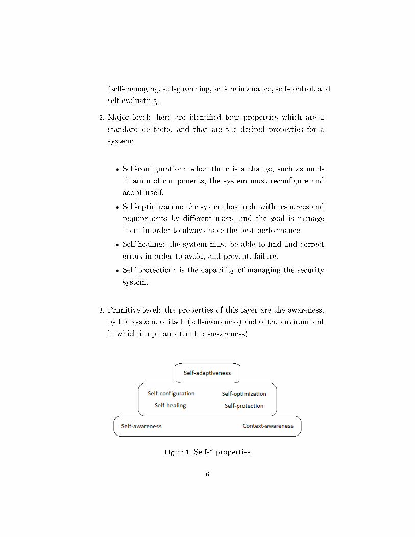
(self-managing, self-governing, self-maintenance, self-control, and
self-evaluating).
2. Major level: here are identi�ed four properties which are a
standard de facto, and that are the desired properties for a
system:
• Self-con�guration: when there is a change, such as mod-
i�cation of components, the system must recon�gure and
adapt itself.
• Self-optimization: the system has to do with resources and
requirements by di�erent users, and the goal is manage
them in order to always have the best performance.
• Self-healing: the system must be able to �nd and correct
errors in order to avoid, and prevent, failure.
• Self-protection: is the capability of managing the security
system.
3. Primitive level: the properties of this layer are the awareness,
by the system, of itself (self-awareness) and of the environment
in which it operates (context-awareness).
Figure 1: Self-* properties
6

When you go to create a self-adaptive software, there are several
issues to consider, which are requirements that have to be considered
in the development.
The �rst decision to make is whether to create a open or closed
system. In a closed system, there is the consideration that there
isn't in�uence from the external environment, so we work with a
�nite number of elements, and the adaptation has to deal only with
this feature in order to implement the adaptation. Instead, in a open
system, the system doesn't know what elements there are, because
they can enter or leave the work environment, so the system has to
�nd all the features that should in�uence its performance.
Another consideration is how to implement adaptation: it can
be anticipated or un-anticipated. In the �rst, the system knows all
the situations in which has to implement the adaptation, and there
isn't the possibility to add new behaviors (closed adaptive). Instead,
in the other solution, the situations are measured runtime, so the
system can perform new behaviors that are computed by using self-
awareness and environmental context information (open adaptive).
It's also possible manage the adaptation externally: the system is
monitored from outside by an application, and some of its model
are maintained at runtime by the observer, which uses this models
when there is a con�ict in order to resolve problems. Changes are
described as operations on the model and imply changes onto the
underlying system.
Other characteristics that the developer must analyze concern,
for example, the level of autonomy that must have the system, if
fully automatically or with human support. Also costs have to be
evaluated when the system implements the adaptation, because can
be signi�cantly to the performance. Must also be selected the infor-
mation that the system will use to make the decision to do or not
the adaptation, and what needs to be changed in each situation.
7

2.2 Software architecture
In the embodiment of a self adaptive system, the architecture is a
key part of the software design and has to satisfy di�erent needs
from di�erent point of view:
• Topology: there can be di�erent interactions among the same
elements, and there is the possibility that new elements enter
the system.
• Behavior: same elements start behaving di�erently, new ele-
ments are injected in the system.
• Control: MAPE elements must be added, and reliability and
robustness must be enforced.
The architecture focuses on the topology of the system and also on
quality attributes (e.g., performance) and on non-functional require-
ments (e.g., cost). It provides an abstract view of a system and its
components are clearly identi�ed. When we de�ne an architecture,
we have to specify also something about components:
• interface (actions that can perform)
• communications and dependencies (how communicate)
• responsibilities (how reacts when it is questioned)
The architecture is not only the structure of the system, but is any
elements of it, and includes the way with which its components are
integrated and how interact.
The main parts of an architecture are the components and the
connectors. A component is an element that is on the system, and
8

can have di�erent levels of detail and granularity. Each component
has a role in the architecture in which it is, and encapsulate related
functions and related data.
A connector is always between components, and model the in-
teractions among them. It separate computation from interaction,
and minimize component interdependencies, and �nally it support
the evolution of the software.
Figure 2: Components and connector
Combining components and connector we create the structure of
our architecture, but, in order to avoid bottleneck, is better avoid
too many dependencies, in particular, the components that change
frequently, must have less dependencies.
The structure built by software architecture is complex and needs
more views, and a possibility is the �4+1� view model [4]:
• Logical view: describes architecturally signi�cant elements of
the architecture and the relationships between them
• Process view: describes the concurrency and communications
elements of an architecture
9

• Physical view: depicts how the major processes and compo-
nents are mapped on to the applications hardware
• Development view: captures the internal organization of the
software components as held in e.g. a con�guration manage-
ment tool
• Architecture use cases: capture the requirements for the archi-
tecture
There are di�erent architectural styles, for example:
• Object-Oriented: objects, that know each other, are related
through messages and method invocations
• Client-Server: some clients share the server, and connect through
their interfaces. The roles are well-de�ned
• Pipe and Filter: components are independent and connected
through pipes, and act like �lters that transform input data
streams into output data streams
• Blackboard: there is a central data structure that is used by
the components for their work
• Rule-based: is composed by a list of rules and an inference
engine that parses input. It searches the knowledge base for
applicable rules and attempts to resolve the input.
• Mobile-code: components outsource the execution of code, that
is represented as a data.
• Publish-Subscribe: the subscriber is put waiting to receive a
certain message or content, and the publisher produces mes-
sages. The information has a one-way �ow
10

• Event-based: independent components produce and receive events
asynchronously, that pass through event buses, so the commu-
nication isn't direct
• Peer-to-Peer: peers are independent entities, each component
in the architecture can act as a client or server for the others,
so the topology can vary arbitrarily and dynamically
• Service-oriented: business functionality is grouped into self con-
tained and reusable units called services, which are autonomous
and discrete units of functionality that are usually accessed re-
motely
2.3 Research
Is possible to identify three di�erent eras in the development of self-
adaptive systems. In the �rst phase, from 1991 to 2000, the software
architecture is used like a design-time tool for systems that need to
be adaptive. The second phase, from 2001 to 2008, has seen the use
of software architecture for self-adaptive systems. Finally, in the
last phase, from 2009 until today, there is an ongoing research on
software architecture.
Now we will see some projects example for each eras.
11

2.4 Phase 1
Figure 3: Phase 1 timeline
2.4.1 Weaves
Weaves, solution proposed by Gorlick and Razouk, are network in
which the components (tool fragments) communicate using objects
in a low-overhead transmission. In this interconnected network, the
data objects are the heart of the information exchange. Each tool
fragment is able to perform a single and well-de�ned action, and
is a thread that receives object as input and produces object as
output. The information in the form of objects can be exchanged
thanks to ports that are attached to queues. Each port is used in
order to connect a tool fragment to queues, which in turn bu�er and
synchronize communication among tool fragments. The queues use
a FIFO role for the stream.
The structure of this architectural style is a pipe and �lter, but
with some di�erences.
12
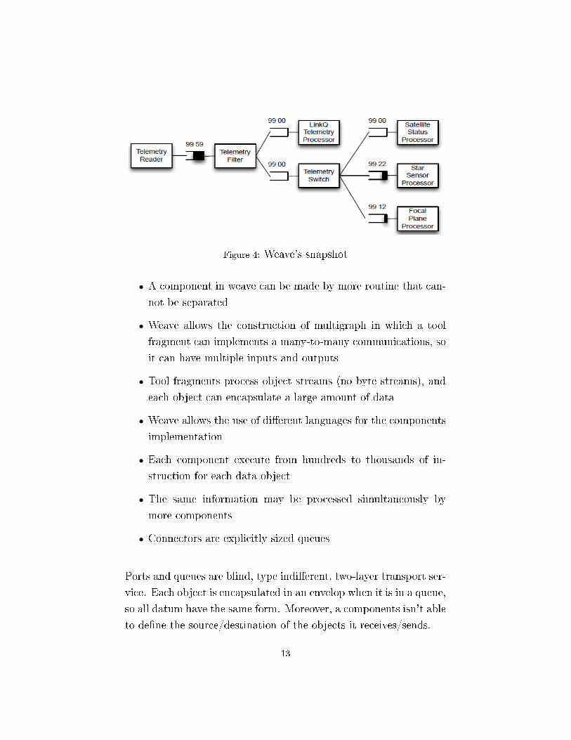
Figure 4: Weave's snapshot
• A component in weave can be made by more routine that can-
not be separated
• Weave allows the construction of multigraph in which a tool
fragment can implements a many-to-many communications, so
it can have multiple inputs and outputs
• Tool fragments process object streams (no byte streams), and
each object can encapsulate a large amount of data
• Weave allows the use of di�erent languages for the components
implementation
• Each component execute from hundreds to thousands of in-
struction for each data object
• The same information may be processed simultaneously by
more components
• Connectors are explicitly sized queues
Ports and queues are blind, type indi�erent, two-layer transport ser-
vice. Each object is encapsulated in an envelop when it is in a queue,
so all datum have the same form. Moreover, a components isn't able
to de�ne the source/destination of the objects it receives/sends.
13
The fact to be blind, increases the �exibility of interconnectivity.
Since the transport mechanism is indi�erent to the type, it is easy
to ensure greater compatibility between components. Weave, also
allows for location transparency. Specialized ports help solve out-
put/input incompatibilities, so when a data is sent through a port,
its delivery is guaranteed (an object can be or inside a component
or in a queue at the same time). When a queue is full, sends an
error to the sender, which waits and tries again.
Tool fragment is the active agent in weaves, and its lifecycle man-
agement include: start, suspend, resume, sleep and abort. There
are two families of tool fragments: one for the inclusion of foreign
routine, and the other for the one that are implemented as weave
components.
The method that can be used in order to analyze weave are three:
1. Self-metric tool fragments
2. Instruments (specialized tool fragments) inserted in the weav-
ing
3. Observers (separation between data capture and analysis)
2.4.2 C2
The new architectural style proposed by Taylor, Medvidovic and
Anderson, is intended for applications that have special require-
ments for the graphical user interface. The main goal is to allow
a more simple reuse of UI's components, but it also achieves other
goals, for example the possibility to write the components in di�er-
ent languages, a dynamic change of the architecture, and some other.
C2 obtains the bene�ts of MVC in a distributed and heterogeneous
setting.
14

This style is a layered network of concurrent components hooked
together by explicit message-based connectors. The basic concept
is to limit the visibility of components, in fact each component in
the hierarchy has only knowledge about what is above it, instead is
unaware of components beneath it. Each component has a thread
of control, but there isn't a shared address space.
Figure 5: A C2 architecture example for an audio-visual stack ma-nipulation system
A component has a top domain, that contains the noti�cation
to which it must respond, and a bottom domain in which there are
the noti�cation that it send down. In each component there is a
wrapped object, that can have di�erent complexity, and that have
an interface used for the noti�cation.
Components are bound thanks to connector: the top of a compo-
nent may be connected to the bottom of a single connector, instead
the bottom may be connected to the top of a single connector. For
a connector there isn't a limit of numbers of elements that can be
15

attached to it.
The communication is asynchronously, and use noti�cations and
requests as messages. Noti�cations �ow from up to down, and are
sent when there is a mutation in the component. Instead, requests
are sent upward in order to require the perform of an action on the
above components.
C2 brings some bene�ts, like the substrate independence, more-
over C2 can easily support for component substitution, support for
concurrent components and for network-distributed systems, and �-
nally, smart connectors can support �ltering policies.
2.4.3 Darwin and Regis
Regis is a programming environment designed by Magee, Dulay
and Kramer, to support the work on distributed programs, espe-
cially with programs consisting of multiple parallel computational
components that cooperate for a common goal. Regis separates the
description of the program structure from the programming of the
functional components, and gives a support in dynamic program
structures managing the increasing complexity.
The computational components in Regis interact via communi-
cation objects, that are executed in a framework programmed in
Darwin. Darwin is a notation that speci�es the high-level organiza-
tion of computational elements and the interactions between those
elements. Components, in Darwin, are composed by services that
they provide and services that they require.
Regis is able to manage the complexity of components intercon-
nection thanks to Darwin that allows construction from hierarchi-
cally structured con�guration descriptions of the set of component
instances. The component interface is based on the notion of pro-
vided and required interfaces.
16
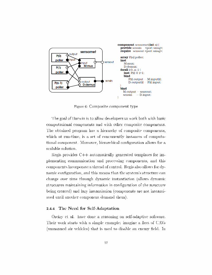
Figure 6: Composite component type
The goal of Darwin is to allow developers to work both with basic
computational components and with other composite components.
The obtained program has a hierarchy of composite components,
which at run-time, is a set of concurrently instances of computa-
tional component. Moreover, hierarchical con�guration allows for a
scalable solution.
Regis provides C++ automatically generated templates for im-
plementing communication and processing components, and this
components incorporate a thread of control. Regis also allows for dy-
namic con�guration, and this means that the system's structure can
change over time through dynamic instantiation (allows dynamic
structures maintaining information in con�guration of the structure
being created) and lazy instantiation (components are not instanti-
ated until another component demand them).
2.4.4 The Need for Self-Adaptation
Oreizy et al. have done a reasoning on self-adaptive software.
Their work starts with a simple example: imagine a �eet of UAVs
(unmanned air vehicles) that is used to disable an enemy �eld. In
17

the brie�ng the mission is planned for an air�eld without defense. In
the midway, intelligence �nds that SAMs are defending the airspace,
so the �eet has to replanning autonomously the mission, and this
lead to two groups of UAVs (a SAM-suppression unit and a air�eld
suppression unit). So, during the �ight, there must be an auto-
matic deploy of new SAM recognition algorithms. In this scenario
components are added to �elded and heterogeneous systems with
no downtime, and from this example is de�ned what a self-adaptive
system is and what it needs. The replanning can be autonomous,
with more distributed planners and can require the human pres-
ence in some case, but always required, as assurances, consistency,
correctness and distributed change coordination.
Reasoning on self-adaptive software, the questions to made, are
di�erent:
• what conditions require the adaptation?
• the adaptation should be open or closed?
• what type of autonomy from human is necessary?
• what are the frequencies of adaptation?
• when the adaptation is cost-e�ectiveness?
• what type of information should be used and with what accu-
racy?
The proposed methodology extends from a small adaptation to one
in large, and develops the technology needed in the entire range of
adaptation.
18

Figure 7: Adaptation methodology
The upper half represents the life-cycle of adaptive software sys-
tems, and in this loop there can be the human presence. The lower
half focuses on the mechanism employed to change the application
software, and the approach is architecture-based.
19

2.5 Phase 2
Figure 8: Phase 2 timeline
2.5.1 Software Product Families
The work of Gomaa and Hussein envolves software product fam-
ily, that is a software architecture that characterizes the similarities
and variations that are allowed among the members of a product
�family�. Their work is part of dynamic recon�guration of software
of the same family. The software con�guration is the process of
adapting the architecture of the product family to create the archi-
tecture of a speci�c product member, and is a solution when there
is an update of the con�guration with the system still working.
The main requirements of the dynamic software recon�guration
are the non interference with the parts that are not a�ected, compo-
nents should complete their activities prior to recon�guration, and
�nally the separation of recon�guration and application concerns.
20

Figure 9: Recon�gurable evolutionary product family life cycle
Each component has an operating statechart (operational trans-
actions), a main recon�guration statechart (explains how the com-
ponent passes through active, passivating, passive, and quiescent
states during recon�guration), one or more operating with recon�g-
uration statecharts (for handling recon�guration events in the oper-
ating statechart), and �nally one or more neighbor component state
tracking statecharts. Everything is brought together by a change
management model.
The proposed change management model, used to de�ne region
in which the recon�guration scenario may be executed, is composed
by two elements:
• Extended Change Rules: a component can only be removed
if quiescent, and the interconnections can be unlinked if the
component is quiescent with respect to those links
• Change Transaction Model: de�nes the actions to do in order
to recon�gure application. Is composed by:
21

1. Impacted Sets: sets of components that must be brought
to quiescence
2. Recon�guration Commands: actions used for the required
changes, are: passivate, checkpoint, unlink, remove, create,
link, activate, restore, reactivate
2.5.2 Architecture-based Self-Repair
With their work, Garlan, Cheng and Schmerl want to realize a
mechanism that allows a run-time adaptation of the system, in order
to increase the dependability of the system. The real problem found
is the determination of the moment in which start the adaptation.
They provides a generalization of architecture-based self-adaptation
by making the choice of architectural style an explicit design param-
eter in the framework.
The architectural style becomes a �rst-class run-time entity, and
his formalization provides a number of important capabilities for
run time adaptation. This kind of use of the style allows to tailor
the framework to the application domain. The style determines:
• what needs to be monitored
• what constraints need to be evaluated
• what to do when there is a violation
• how to perform the repair
In order to make the style useful at run time, it is augmented with
a set of architectural operators for the style, and with a collection
of repair strategies written in terms of these operators.
22

Figure 10: Adaptation Framework
The generic model comprises Components and Connectors with
explicit interfaces: ports (component interfaces) and roles (connec-
tor interfaces). Components can be further re�ned through repre-
sentations, that are more detailed description of the architecture.
Semantic properties are described through graph annotation, that
have the advantage of being general.
Are also de�ned repair strategies that correspond to selected con-
straints of the style. The function of a repair strategy is to determine
a problem's cause and how to �x it, and its form is a transactional
sequence of tactics. Each tactic has a pre-condition and a repair
script.
2.5.3 Operations and Strategies
Hawthorne and Perry focused their research on prescriptive ar-
chitecture, which derives the implementation architecture from the
requirements. The goal of this work is to bridge the gap between
requirements engineering and software architecture. The system re-
23
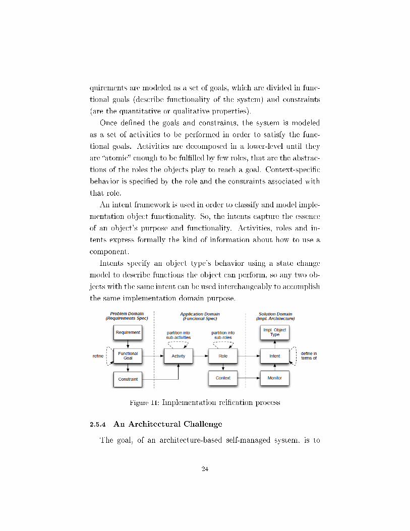
quirements are modeled as a set of goals, which are divided in func-
tional goals (describe functionality of the system) and constraints
(are the quantitative or qualitative properties).
Once de�ned the goals and constraints, the system is modeled
as a set of activities to be performed in order to satisfy the func-
tional goals. Activities are decomposed in a lower-level until they
are �atomic� enough to be ful�lled by few roles, that are the abstrac-
tions of the roles the objects play to reach a goal. Context-speci�c
behavior is speci�ed by the role and the constraints associated with
that role.
An intent framework is used in order to classify and model imple-
mentation object functionality. So, the intents capture the essence
of an object's purpose and functionality. Activities, roles and in-
tents express formally the kind of information about how to use a
component.
Intents specify an object type's behavior using a state change
model to describe functions the object can perform, so any two ob-
jects with the same intent can be used interchangeably to accomplish
the same implementation domain purpose.
Figure 11: Implementation rei�cation process
2.5.4 An Architectural Challenge
The goal, of an architecture-based self-managed system, is to
24
minimize the degree of explicit management necessary for construc-
tion and subsequent evolution whilst preserving the architectural
properties implied by its speci�cation. Architecture provides the re-
quired level abstraction and generality to deal with self-management,
and also can help with the scalability, can be combined with existing
work, and has a potential for an integrated approach. The solution
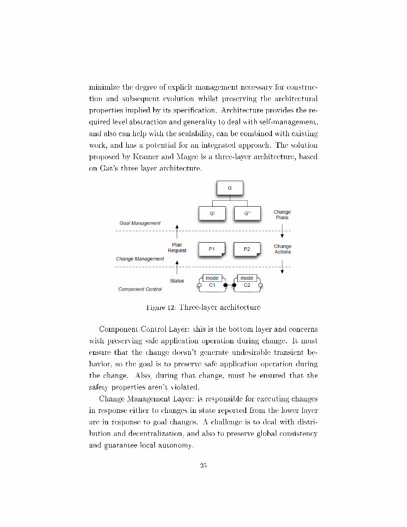
proposed by Kramer and Magee is a three-layer architecture, based
on Gat's three layer architecture.
Figure 12: Three-layer architecture
Component Control Layer: this is the bottom layer and concerns
with preserving safe application operation during change. It must
ensure that the change doesn't generate undesirable transient be-
havior, so the goal is to preserve safe application operation during
the change. Also, during that change, must be ensured that the
safety properties aren't violated.
Change Management Layer: is responsible for executing changes
in response either to changes in state reported from the lower layer
are in response to goal changes. A challenge is to deal with distri-
bution and decentralization, and also to preserve global consistency
and guarantee local autonomy.
25

Goal Management Layer: the problem is to have a precise spec-
i�cation of the goals required of a system, and the challenge is to
achieve goal speci�cation such that it is both comprehensible by hu-
man and machine. There are also challenges in the decomposition
of goals and in the generation of operationalized plans.
2.6 Phase 3
Figure 13: Phase 3 timeline
2.6.1 Situated Multi-Agent Systems
Weynes and Holvoet, proposed a solution in which the software
is structurated in autonomous entities (agents) situated in an envi-
ronment, (situated MAS) and is valuated the ability of the agents
to adapt themselves during the change. The agents employ the en-
vironment to share information and coordinate their behavior. The
control, in this solution, is decentralized, because is divided among
the agents. Instead, the self-management is the system's capabil-
ity to manage dynamism and change autonomously, that are the
variables that a�ect the system during operation.
26

Figure 14: Types of architectural approaches
Each agent is composed by three subcomponent:
• Perception: is a �ltered sensing of the environment, collects
runtime information
• Decision Making: is responsible for action selection through the
in�uence-reaction model
• Communication: is responsible for communicative interaction
with other agents
Communication and decision making are kept separate because in
this way there is a clear separation of concerns, and both functions
can act in parallel and proceed at di�erent paces.
The decomposition of the application can be considered in two
dimension: horizontal (based on the distinct ways agents can access
the environment) and vertical (based on the distinction between the
high-level and the low-level interactions).
2.6.2 Management and Visualization
A continuous control of a runtime adaptive software system is
nearly impossible, so the work of Georgas, van der Hoek and Taylor,
27

wants to realize the vision of an operations control center through
which human users can understand and manage runtime adaptive
software systems. This operations control center can contextualize
current and past behavior with respect to the system con�gurations
that resulted in these behaviors, support retroactive analysis of his-
torical information about a system's composition and behavior, and,
�nally, connect to operator-driven proactive management of the sys-
tem.
Figure 15: ARCM visualization tool
The main result is a historical graph of architectural con�gura-
tions organized along three dimension:
• visibility: to see what happened
• understandability: to improve adaptation
• management: to rollback or push the system into an existing
con�guration
ARCM graph is a directed cyclic graph G=(N,E) with N the set of
28
nodes and E the set of unidirectional edges between nodes. Each n
in N de�nes a speci�c architectural con�guration, and each e in E
is de�ned by a head and a tail node, capturing an adaptation that
modi�ed the tail con�guration in the one of the head.
2.6.3 Stitch
Is a language for de�ning and automating the execution of adap-
tation strategies in an architecture-based self-adaptation framework
made by Cheng, Garlan and Schmerl.
The requirements for Stitch are:
• adaptation decision processes should be able to choose the next
action depending on the outcome of previous ones
• when evaluating the result of an adaptation action the language
should take into account that e�ects could be susceptible to
delay
• strategies should be �guarded� by activation conditions
• should be possible to determine the best strategy to execute if
there is more than one
• past successes or failures to adapt should contribute to the
overall process
Stitch de�nes adaptation strategies as decision trees built up from
adaptation tactics, which are in turn de�ned in terms of more prim-
itive operators. The most primitive unit of execution for an adapta-
tion process is the operator, that is determined by the architectural
style. A tactic is an abstraction that packages operators into larger
units of change. A tactic contains a sequence of operator calls, acti-
vation preconditions, a de�nition of e�ects that it is attempting to
29

achieve, and an impact vector that speci�es how it will impact the
system's quality dimensions. In a strategy, each step is the condition
execution of a tactic, and it's characterized as a tree of condition-
action-delay decision nodes. Each strategy has a context-based ac-
tivation condition, and allows for the calculation of an aggregate
utility function.
The strategy selection is made choosing the strategy with the
highest utility. This is achieved through the de�nition of quality
dimensions, utility preferences, impact vectors and branch proba-
bilities.
2.7 Open issues
How we have just seen, the years of work in self-adaptive systems
are many but, despite this, the work in this area is still a challenging
task.
For example the development of patterns that give guarantees
of e�ciency in some areas [16]. A system often needs to perform
a trade-o� analysis between several potentially con�icting goals, so
there is the need of practical techniques to de�ne utility functions.
There is also a need for more research in the de�nition of lightweight
monitoring techniques, in order to avoid that the e�ort in monitor-
ing exceeds the bene�ts of improvements in QoS after an adaptation.
Control-loops are essential for self-adaptive systems and the applica-
tion of the centralized control-loop pattern to a large-scale software
system may su�er from scalability problems, so is necessary an ap-
proach that integrates both control-loop and decentralized agent.
The research has to focus also on more advanced and predictive
models of adaptation in order to avoid a system to fail after a change
to satisfy his requirements. The characteristics of self-adaptive sys-
tems create new challenges for developing high-assurance systems,
30
and novel veri�cation and validation methods are required to pro-
vide assurance in this system.
A-3 focuses on high-volume and highly volatile distributed sys-
tems, that have very strong coordination requirements, and are hard
to design. This kind of system has the need to be �exible to adapt
to frequent changes in the execution environment or in the system's
available resources. A-3, and so also A3JG, is able to coordinate the
behaviors of multiple elements, so that they can reach a common
goal.
31

3 Dynamic Group Management
The idea is to create a middleware that allows the realization of
distributed high-volume and highly volatile systems. These systems
need to be able to self-adapt and to disseminate new con�guration
tasks, depending on the needs and availability of its components.
A simple environment that allows to de�ne an example to better
understand the characteristics of A-3, is a supermarket. Imagine a
system in which the nodes are the shopping carts, the checkouts,
and a �controller�. Our goal is to coordinate these entities in order
to optimize checkouts, and to reduce the amount of waiting time
that customers pays in the queue.
3.1 Group view
The main idea of A-3 is to reason on groups of node, instead of
on single entities. More clearly, the individual entities are grouped
on (eg) similar characteristics and behaviors (the policy is left open
and decided by the system designer). Then a developer needs to
coordinate the groups, which are seen as entities that are easier to
coordinate. This allows for an easier de�nition of the interactions
between entities. In fact a group allows multiple elements to be
treated as a single less dynamic block. In this way, each entity may
enter or leave the system freely, and the problem is reduced to the
smaller one of managing groups.
32

To develop a system with A-3 it is therefore necessary to de�ne
what groups that will be present, and characterizes them. To do
this, we need to de�ne the roles the nodes will play within a group.
In particular, A-3 allows two di�erent kinds of roles: supervisor and
follower. In each group there is only one supervisor and one or more
followers (as many as required and as supported by the network).
The supervisor's task is to coordinate the followers, which join a
group for advice on how to behave depending on the situation at
hand. Each entity can be both supervisor and follower in more than
one group, but they can have only one active role for each group in
which they participate.
By comparison with the C2 project, the roles of A-3 correspond
to the components of the �rst, while there is a single connector that
enables the exchange of messages in each group (see 3.2). Also in
Weaves there is the distinction between components and connector,
but there aren't speci�c di�erent roles between components.
In A-3, while the supervisor has knowledge of the group's struc-
ture and of its members, the follower node may not know how the
group is structured.
In the example of supermarket we can, for example, de�ne a
group �CHECKOUTS�, in which the supervisor is the controller and
the followers are all the active checkouts. Another group could be
the �CARTS� that run in the supermarket; once again the controller
could be the supervisor. We have N other groups �CHECK_#�, in
which the checkout number # is the supervisor, and the carts in the
queues are the followers.
33

Figure 16: Group view in supermarket's example
Figure 16 shows groups. Triangle indicates controller, squares
represent checkouts, and circles represent carts. Each color corre-
sponds to one of the groups we de�ned before.
3.2 Communication
In order to achieve coordination A-3 allows nodes inside each group
to communicate. The kind of communication is di�erent based on
role.
The supervisor can send messages:
• in broadcast, to each member of the group
• in multicast, to some members of the group
• in unicast, to only one follower of the group
Instead, a follower can only send message to its supervisor; commu-
nication between followers isn't allowed (it must be out of band). All
34

messaging is asynchronous. Moreover, the supervisor can communi-
cate with its followers even when they are o�ine, because messages
can be saved in memory, such that they can be delivered it when
followers join the group. The message remain available for a cer-
tain amount of time, so after this period the message is deleted.
Followers can also send updates to their supervisors. For example,
They can send messages to allow to know that the sender joined
the group or that its status changed. The kinds of noti�cations are
optional. The developer can use them, for example, to keep trace of
each group's population.
In the work of Taylor at al., the communication is more limited,
in one direction making requests, the other noti�cations, and the
messages can only move one step at a time, but we can imagine the
separation between components of two di�erent level as a separa-
tion between groups, but in A-3 components of the same group can
communicate. This is, also, di�erent from Weaves, where a message
is an object, but no component knows the source (destination) of
a received (sent) object. It is more free respect to A-3, where each
component knows the sender (receiver) of its messages.
In the case of the supermarket, for example, the controller may
send messages to the crates to tell them to stay open/closed based
on the amount of waiting customers, while the carts can tell the
controller the amount of objects that are carrying, so that the su-
pervisor can better manage also checkouts and send them to the
most appropriate queue.
3.3 Group collaboration
So far we have seen how the individual groups are coordinated inter-
nally with A3, but in a large-scale system, groups may wish to work
35

together. In order to realize the collaboration, A-3 allows to group
composition. This is achieved by allowing single element to work in
di�erent groups, with di�erent roles. This allow for di�erent com-
positions in which each single element that is shared between two or
more groups can, therefore, share information between these groups.
Figure 17: Group composition
Figure 17 shows three groups (red, green and blue). Two follower
nodes of the �red� group, are also supervisors in the other groups,
this because for a node, you can have di�erent roles in di�erent
groups. These two node are also responsible for the coordination
between groups �red-green� and �red-blue�, and their work in the
beneath clusters in�uences the working cycle of the �red� group.
Instead the �green� and �blue� groups share follower. Moreover, a
follower of the �blue� group is also supervisor in the �red� group,
and this creates a nested composition.
The possible type of composition are three.
36

3.3.1 Shared Followers
We can have a supervised component that simultaneously belongs
to two groups, and the supervisors of these groups can collaborate
using the shared follower as an intermediary for messages. The fol-
lower can also receives con�icting coordination directives from the
two supervisor, and in this case it is up to the component itself
to manage and resolve the con�ict, since the con�guration doesn't
support explicit coordination between the two supervisors. In the
supermarket's example, each cart is a follower in both the groups
in which it participates, so they are shared follower (�gure 16, cir-
cles are shared supervised components). Figure 17 shows this com-
position between groups �green� and �blue� which have a node in
common.
3.3.2 Hierarchical composition
Another possible composition is the hierarchical one, in which a su-
pervisor has a follower that is supervisor in another group. This
component contributes to the top group with a digest of the knowl-
edge it collects from the bottom group. This allows the top group's
supervisor to have a complete view of the system, without having
to interact with all the components in the system. In this case, the
supervisor in the high level is a centralized coordinator. This case is
shown in the example of the supermarket between the controller and
all its checkout followers, because each checkout is also supervisor
in the group �CHECK_#�.
3.3.3 Nested composition
In A-3 is allowed to have a structure in which all the supervisor
are also follower in another group, so there isn't only one node able
to see the entire system, but all supervisor nodes in a circle struc-
ture have a complete view of the system. To avoid in�nite nesting
37

coordination directives, each supervisor only sends directives to its
own supervised components using multicast messages, and avoids
sending them to the other supervisor. The resulting coordination is
completely distributed. In �gure 17 there is this kind of composition
thanks to the two �red� followers that are supervisors in �green� and
�blue�, and the �blue� follower that is supervisor in �red�. In this
example �red� and �blue� supervisors have a complete view of the
system.
3.4 Safe Group Management
A-3 also allows supervisor to store important data, or anything else
that needs to be tolerant to fault and easily recoverable when nec-
essary, to distributed memory in a redundancy fashion.
The architecture, supports continuous node exchanges. If a fol-
lower enters/exits, no problems arise, because the other nodes are
not actually interested in knowing who is in the group, while the su-
pervisor will change the workload of those who are connected. The
extreme case is the one in which the entry of a new node makes
the size of the group too large, requiring the group to split. In this
situation the supervisor must decide which nodes should migrate
to the new subgroup, because is the only one that has knowledge
about the group's structure. Vice versa, when the size of the group
is too small, the supervisor has to merge multiple groups. All this
movement of nodes and changes of the structure aren't visible at
the application layer, because the user of the system can see only
one group with all his nodes.
In the supermarket environment, follower tra�c is due, for ex-
ample, to the opening or closing of a checkout, or to the arrival of a
new cart in the payzone.
If a supervisor leaves the group we have a delicate situation:
since there is only one supervisor in a group, and it must always be
38

present. When it dies the followers must take the responsibility of
keep the group alive. How? Simply by starting an election to �nd
the new supervisor, who can use the information saved from pre-
vious supervisor in the replicated memory to immediately update
its status and continue to manage the group as if nothing had hap-
pened. Otherwise, without replacement, the group has no reason
to exist because there would be no coordination of internal nodes.
The possibility to elect and save data in memory is very important,
because it avoids the supervisors from becoming single points of fail-
ure. In fact, if it periodically stores important data in the group,
when it fails, the new supervisor can retrieve these information and
continue the coordination of the followers with minimum delay.
39

4 The A-3 Framework
A3JG is an open-source implementation of A-3 made by me, that
allows the implementation of self-adaptive systems. It is built using
JGroups, that is a group communication middleware. In this work,
JG is also used for managing groups.
Now we will see how A3JG is implemented, and what a developer
needs to do in order to use it for his/her application.
4.1 Architecture
Figure 18: A3JG Architecture
40

In the lowest level of the architecture, we have JGroups which is an
open source project that provides tools for managing groups and,
in particular, in this work it is responsible for all the connections
and the transfer of messages exchanged. In the middle there are
all the nodes that are distributed, also in di�erent locations. Each
node is unique and is responsible for managing its roles, that are
stored in two distinct map (one for the supervisor and one for the
follower). An application needs to implement the nodes (e.g. one
for each distributed host) and the roles, and then to connect them
to a group.
4.2 JGroups
As already said, A3JG uses di�erent features of JGroups, in partic-
ular to manage the groups (which in JG are called clusters) and the
communication between groups.
4.2.1 What is JG?
JGroups is a project that aims to build a reliable communication
between members of a group. The communication is in multicast
and it can use both IP and TCP as transport (the protocol stack is
�exible to every need).
JG allows developers to create (automatically when a node joins
a group that doesn't exist) and delete clusters. Each group can be
populated with members coming from LANs and WANs. It also pro-
vides tools to receive noti�cations about changes that occur within
the cluster. Each group is distinguishable thanks to the name.
4.2.2 Main features
The channel allows the nodes to join a group, and then to work with
41

the other members. Through the channel, each member sends and
receives its messages, and can be used only by one node. To be able
to see the messages and the noti�cations, it is necessary to pass a
receiver (ReceiverAdapter) to the channel.
A channel can be connected only to one group so, if a node has
to work in multiple groups, it needs more channels. Each channel
is distinct thanks to a unique address, and has a view with the
addresses of the other members in the cluster.
You can use an XML �le to pass con�guration parameters of the
channel, and this happens when a channel is created (if you do not
pass the �le, JG uses the default con�guration).
JGroups provides building blocks to make the most of what it
o�ers the channel, without having to rewrite the code base. From
an architectural point of view, they are on a layer above the channel,
and they are used when the developers need high-level interface. A
building block widely used in A3JG is the ReplicatedHashMap.
Finally, the protocol stack plays an important asset in JGroups.
In fact, it is so �exible that can adapt to any application. It's com-
posed by many levels of protocols, that are passed in a bidirectional
way, then any message that is sent or is received, has to cross all the
layers. The realization of the stack depends on the XML �le that
the developer can use to create the channel. This thing shows how
you can create di�erent con�gurations based on need.
4.2.3 JG in A3JG
A3JG uses di�erent features of JGroups. To connect to a group,
a node uses a JChannel, and the active channels are saved in a
map on the node (the map's key is the name of the group). The
channel is used to create a new cluster (group) or to connect to an
existing one. Through the channel all the communication between
the nodes �ows. It's possible to pass a speci�c con�guration of the
42

protocol stack through a XML �le, but if no �le is passed, the default
con�guration is used.
In order to save information about the current state of the group,
save messages and manage the election of a new supervisor, A3JG
uses the ReplicatedHashMap, that is a concurrent hashmap shared
between each member of the cluster. Indeed, A3JG makes use of a
modi�ed version of RHM, in fact, to be able to freely manage the
function viewAccepted, it was necessary to create a copy (viewAc-
ceptedOriginal) that is invoked whenever there is a change in the
group. Keys, which are already used by A3JG on the map, not to be
used for a correct work are: �A3Supervisor�, �A3SupBackupState�,
�A3SharedState� + int, �A3Message�, �A3MessageInMemory_� +
int, and all JChannel address.
It's possible to share a state, on the map, between supervisor and
followers using:
and save a supervisor backup state using:
Both A3JGSupervisorRole and A3JGFollowerRole implement Re-
ceiverAdapter, to allow them to send messages to other members of
the group and to receive updates on changes of the structure of the
group. The ReceiverAdapter is used in order to receive message sent
43

to the channel, and to see when the View is changed. The View is a
list that contains all the active nodes in the cluster at the moment
it is called.
A3JGRHMNoti�cation class, instead, implements Noti�cation of
ReplicatedHashMap, and can be used to see all the modi�cation of
the RHM and how change its entirety.
4.3 A3JGNode.class
This is the �rst class that the developer needs to extend (it's an ab-
stract class). A3JGNode identi�es a single and autonomous device
that is connected in the distributed system, and that has its own
features and functionality. As already said, in A-3 every node can
be inserted in one or more groups, and this property also occurs in
A3JGNode, because it is possible to de�ne multiple roles which the
node can employ and the groups in which it can work.
4.3.1 How de�ne a node
Therefore every node is an independent unit of work, for this reason
each A3JGNode has an unique identi�er, and this �ID� is de�ned
at the creation time, through the constructor (is a String). Being a
physical unit, it is also characterized by a �resourceThreshold�, that
cannot be exceeded (is an integer). This last value can be changed
using getter and setter. Two other attributes that the developer can
modify are �timeout� and �inNodeSharedMemory�, but we will see
their function later.
After its creation, a node needs to be �lled with something else
by the developer, in particular he/she has to work with three maps:
�supervisorRoles�, �followerRoles� and �groupInfo�. In order to make
the node able to work, the roles of supervisor and follower must be
added, which are stored in the two separated maps. Each node must
44
be able to act in di�erent groups with di�erent behaviors depending
on the situation, so it's necessary to de�ne the instructions of the
behavior that the node must implement in each group which can
participate. In these maps there are only the instruction (the keys
are names of role's classes) that can be shared between multiple
groups.
In order to connect the node to one group is also necessary to pass
the information relating to the cluster where you want to join. This
is done using A3JGroup, and this information is saved in �groupInfo�
with the name of the group as key.
In �gure 19 there is an example of a node after the insertion of
information of some roles and groups (for simplicity, from now on,
the groups will be named with color).
45
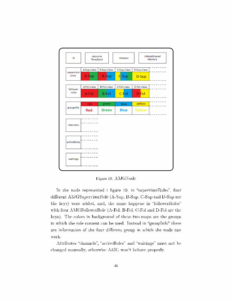
Figure 19: A3JGNode
In the node represented i �gure 19, in �supervisorRoles�, four
di�erent A3JGSupervisorRole (A-Sup, B-Sup, C-Sup and D-Sup are
the keys) were added, and, the same happens in �followerRoles�
with four A3JGFollowerRole (A-Fol, B-Fol, C-Fol and D-Fol are the
keys). The colors in background of these two maps are the groups
in which the role content can be used. Instead in �groupInfo� there
are information of the four di�erent group in which the node can
work.
Attributes �channels�, �activeRoles� and �waitings� must not be
changed manually, otherwise A3JG won't behave properly.
46

4.3.2 Join a group
After these steps, it is possible to connect the node to a group using
the join function. Now, depending on the type of the application to
be implemented, the value to assign to �timeout� must be evaluated,
which is by default 10000. This attribute indicates the milliseconds
in which JGroups try to fetch the state of the ReplicatedHashMap
used in the group. In order to modify the value, you can use the
setter.
To call the �joinGroup� function, it is only necessary pass the
name of the group that you want to join.
Another possibility is the joinAsSupervisor function (compared
to regular join it has also a boolean as input), that force the election
of the node as the supervisor of the group.
With this function it is possible for the node to be directly elected
as a supervisor (passing it the parameter �challenge� equal to False)
or take a challenge with the supervisor in charge, if any (passing
it the parameter equal True). In the �rst case, the old supervisor
tries to become a follower of the group if it has the role, otherwise
it terminates. In the second case, the winner of the challenge will
be the supervisor of the group, instead the loser tries to become a
follower of the group if it can.
47

Both the functions work in the same way. At the beginning
there is a control on the list of existing active channels, that are
saved in the �channels� map (the key is the name of the group). If
already exists a channel with key equal to �groupName�, the function
end. Then there is a control on groupInfo, if the node doesn't have
information about the group to join, the function ends.
Now we know that we can join the group, so the channel must be
created and, before the creation, there is a control on �groupInfo�
in order to recover the XML con�guration �le of the channel (if it
exists). After the creation, the channel is put on �channels� map,
and the key is �groupName�. Before connecting the channel, the
ReplicatedHashMap is created, then the function tries to connect
the channel to the group referred, �nally, after the connection, the
RHM is updated.
After these steps the role that the node will use to work in the
group in which it's connected is activated (�true� if the node has
joined the group, false otherwise).
The return of both functions is the success of the join operation.
48
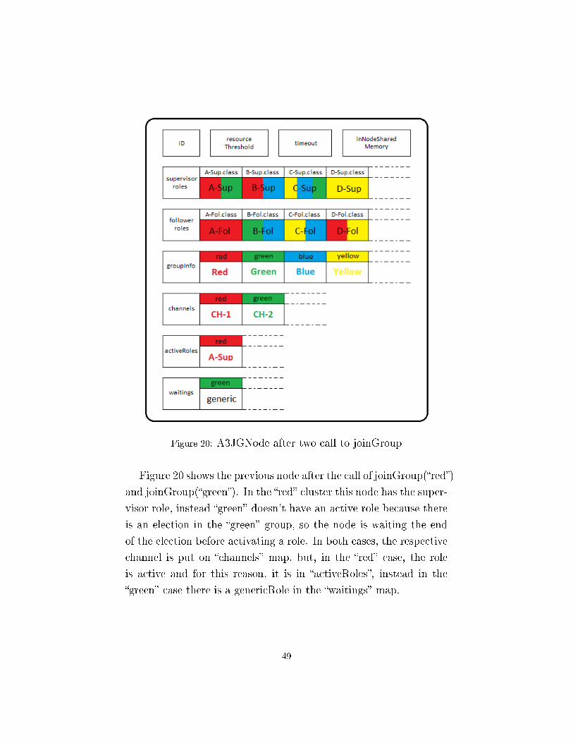
Figure 20: A3JGNode after two call to joinGroup
Figure 20 shows the previous node after the call of joinGroup(�red�)
and joinGroup(�green�). In the �red� cluster this node has the super-
visor role, instead �green� doesn't have an active role because there
is an election in the �green� group, so the node is waiting the end
of the election before activating a role. In both cases, the respective
channel is put on �channels� map, but, in the �red� case, the role
is active and for this reason, it is in �activeRoles�, instead in the
�green� case there is a genericRole in the �waitings� map.
49
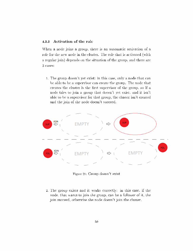
4.3.3 Activation of the role
When a node joins a group, there is an automatic activation of a
role for the new node in the cluster. The role that is activated (with
a regular join) depends on the situation of the group, and there are
3 cases:
1. The group doesn't yet exist: in this case, only a node that canbe able to be a supervisor can create the group. The node thatcreates the cluster is the �rst supervisor of the group, so if anode tries to join a group that doesn't yet exist, and it isn'table to be a supervisor for that group, the cluster isn't createdand the join of the node doesn't succeed.
Figure 21: Group doesn't exist
2. The group exists and it works correctly: in this case, if thenode, that wants to join the group, can be a follower of it, thejoin succeed, otherwise the node doesn't join the cluster.
50

Figure 22: Group exists
3. The group is already existing, but there is the supervisor elec-tion: in this case a new comer has to wait until the end ofthe election to receive the assignment. The role of this nodeduring the election is the GenericRole (it can receive messagesand participate to the election). At the end of the election, ifthe node won the election, it becomes the new supervisor oth-erwise, if it is capable, becomes a follower. If no one is ableto become a supervisor, the group is destroyed, because theremust always be a supervisor.
51

Figure 23: Join during election
4.3.4 Communication between groups
Previously, we have seen how the communication between groups
is via roles that are implemented in the same node. This thing is
realized here through a shared memory space saved in the node,
it can be used by any active role of the group, and can be seen,
obviously, by all the active followers and supervisors of the same
node.
This space is �inNodeSharedMemory�, an it is where an object,
that will be de�ned by the developer depending on the application
52

that wants to realize, can be saved. Roles access it using getter and
setter.
4.3.5 Leave the group
When a node no longer wants to be part of a group, it can call the
terminate function, that terminates the role's thread and closes the
JChannel.
From �channels� and from �activeRole� the values that have key
equal to �groupName� are removed.
Now, if the node wants to participate to the work of that group,
it needs to recall the joinGroup.
4.4 A3JGSupervisorRole.class
The developer must extend beyond the node, other two classes,
which are used to de�ne the behavior of the supervisor and of the
follower. These two (abstract) classes are A3JGSupervisorRole and
A3JGFollowerRole, which extend ReceiverAdapter and implement
Runnable.
4.4.1 The supervisor role
This class must be extended every time you want to de�ne a new
kind of supervisor.
As already seen, the supervisor is the leader of the group, and
the one that controls the work of the followers giving them informa-
tion through messages. It is the core of the cluster, and everything
53

revolves around it, so it is necessary to have always an active super-
visor in each group, and when it dies, it must be replaced otherwise
the cluster is closed.
The supervisor is also the one that can create a new group when
this doesn't exist yet, while the follower, as we have seen, doesn't
have this capacity.
So the idea in A-3 is that it is the supervisor the node with
capacities for managing the fate of the group through its decision,
for this reason it's the one that can implement the MAPE control
loop. An automatic manager uses this loop, that is composed by
four parts (Monitoring, Analysis, Planning and Execution), in this
way: �rst information are captured from the external environment
and the agent analyzes them in order to identify the best behavior
to be taken to achieve its goal in this situation, then it performs
the chosen actions. In fact, only the supervisor has the tool to
receive information by all the members of the group, and to send
the directives to all other participants. The MAPE control loop
isn't yet deployed in A3JG, but is a future work.
4.4.2 Structure
The supervisor has di�erent attributes. There is a boolean (�active�)
that is used in order to de�ne the status of the role, an integer that
represent the cost of the role (�resourceCost�), a long that is used
to indicate the time to split the group and by default it is equal to
1000 milliseconds (�splitTime�), the channel used to connect to the
cluster (�chan�), the A3JGNode membership of the role (�node�),
the ReplicatedHashMap used to exchange some information with
the other members (�map�), an instance of MessageDelete (�deleter�)
and an integer (�index�) used by the message �deleter� and we will
see later its function, an A3JGRHMNoti�cation to get notify from
RHM (�noti�er�), and the last is a boolean used when the group is
54

splitted.
Of all these attributes, the only two that must be set by the
programmer are those related to the costs (it's passed with the con-
structor, and it can be changed with the setter) and to the split
time, the others are managed by A3JG.
4.4.3 Functions to extend
This class implements Runnable, so the run function of the thread
and must be extended, in addition to it, also other three functions.
The run function is the one where the developer will put the
behavior of the supervisor, and here the MAPE control loop (or the
control can substitute the run function) can be put.
The �rst and the second function in the picture, are used in
order to implement the communication between members of the
same group.
The �rst is called whenever a follower sends a message to the
supervisor, so in it there must be the code necessary to enable the
supervisor to manage the received message (�msg�). For example,
the supervisor can react to every received message, or can save the
messages in memory and read them in a di�erent moment, both the
behaviors can be implemented in �messageFromFollower�.
Instead, the second function is called whenever an update from
a follower arrives to the supervisor. Also here the content of the
update is �msg�, and the kind of the update depends on how the
55

application is implemented by the programmer. The developer can
manage the update as preferred according to the type of system that
he/she wants to realize.
Both the functions are called by the implementation of the �re-
ceive� function of JGroups, that is present in A3JGSupervisorRole
class.
The last function in the picture is the �tness function that is used
when there is a supervisor election or someone outside the group
calls a �joinAsSupervisor�. The function must return an integer
that indicates how much is convenient to choose a node to be the
new supervisor with respect to the others (for nodes which cannot
be a supervisor in the group of the election, this value is set to 0
by default). This value is very important because it let the node to
be the supervisor of the group, and the goal is to have as the leader
a node that doesn't slow down the work of other members. You
should consider in this function, for example, how much free space
there is in the node.
4.4.4 Send message to followers
In order to send message to the other members, there are two func-
tions available for the supervisor.
These two methods are very similar. The A3JGMessage (see 4.6)
is set as content of a message de�ned by JGroups, and it is sent with
the send method of the channel. The �rst is used when you want to
56
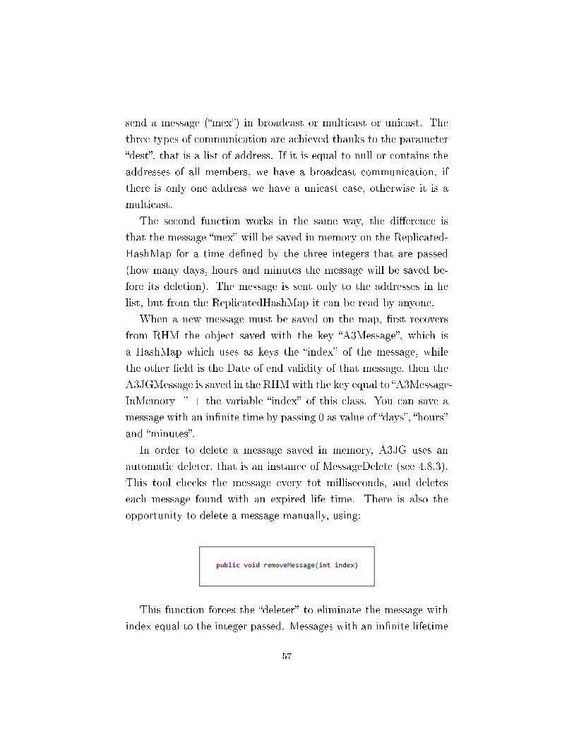
send a message (�mex�) in broadcast or multicast or unicast. The
three types of communication are achieved thanks to the parameter
�dest�, that is a list of address. If it is equal to null or contains the
addresses of all members, we have a broadcast communication, if
there is only one address we have a unicast case, otherwise it is a
multicast.
The second function works in the same way, the di�erence is
that the message �mex� will be saved in memory on the Replicated-
HashMap for a time de�ned by the three integers that are passed
(how many days, hours and minutes the message will be saved be-
fore its deletion). The message is sent only to the addresses in he
list, but from the ReplicatedHashMap it can be read by anyone.
When a new message must be saved on the map, �rst recovers
from RHM the object saved with the key �A3Message�, which is
a HashMap which uses as keys the �index� of the message, while
the other �eld is the Date of end validity of that message, then the
A3JGMessage is saved in the RHMwith the key equal to �A3Message-
InMemory_� + the variable �index� of this class. You can save a
message with an in�nite time by passing 0 as value of �days�, �hours�
and �minutes�.
In order to delete a message saved in memory, A3JG uses an
automatic deleter, that is an instance of MessageDelete (see 4.8.3).
This tool checks the message every tot milliseconds, and deletes
each message found with an expired life time. There is also the
opportunity to delete a message manually, using:
This function forces the �deleter� to eliminate the message with
index equal to the integer passed. Messages with an in�nite lifetime
57
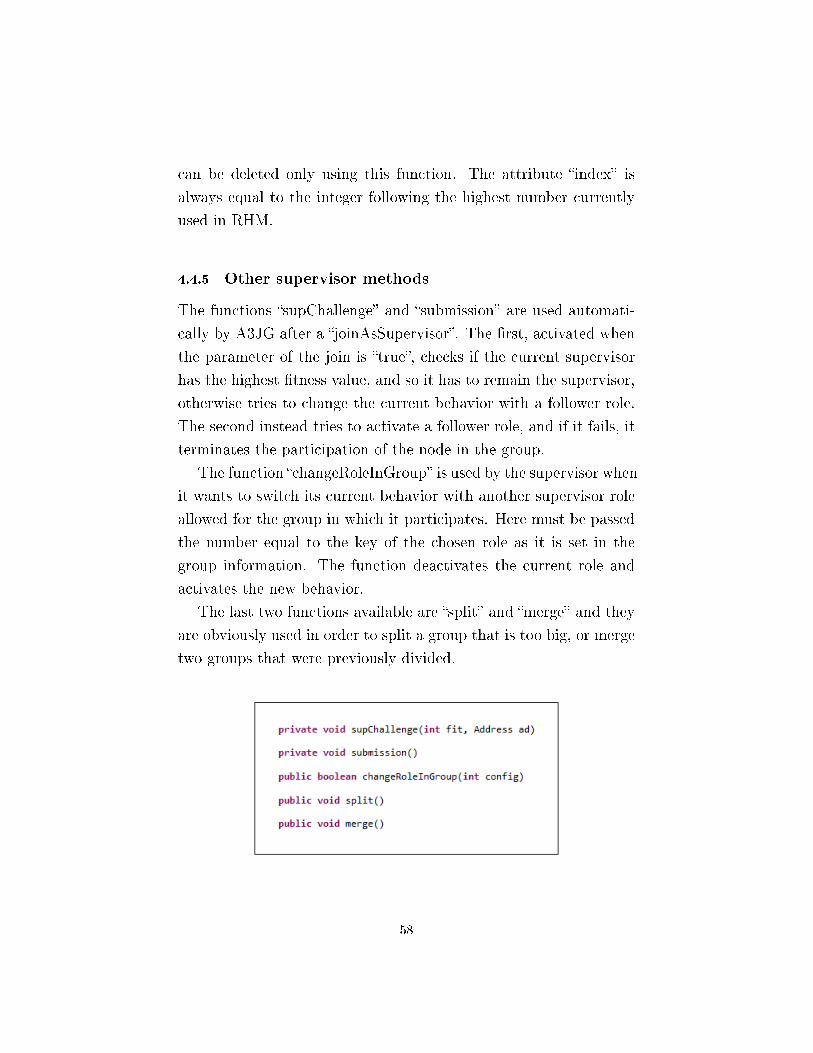
can be deleted only using this function. The attribute �index� is
always equal to the integer following the highest number currently
used in RHM.
4.4.5 Other supervisor methods
The functions �supChallenge� and �submission� are used automati-
cally by A3JG after a �joinAsSupervisor�. The �rst, activated when
the parameter of the join is �true�, checks if the current supervisor
has the highest �tness value, and so it has to remain the supervisor,
otherwise tries to change the current behavior with a follower role.
The second instead tries to activate a follower role, and if it fails, it
terminates the participation of the node in the group.
The function �changeRoleInGroup� is used by the supervisor when
it wants to switch its current behavior with another supervisor role
allowed for the group in which it participates. Here must be passed
the number equal to the key of the chosen role as it is set in the
group information. The function deactivates the current role and
activates the new behavior.
The last two functions available are �split� and �merge� and they
are obviously used in order to split a group that is too big, or merge
two groups that were previously divided.
58

4.5 A3JGFollowerRole.class
4.5.1 The follower role
This class is used to de�ne the behavior of followers. In a group
there may be more than one follower, but all of them talk only with
the supervisor. We can see the follower as units of work coordinated
by the decisions of the supervisor. The goal is to make sure that the
followers are able to send the information that the supervisor needs
to de�ne the strategy of work. Followers must also understand and
implement what they are told by the supervisor of the group.
4.5.2 Structure
The structure of the class is similar to that of the supervisor. The
attributes, that a follower has, are: a boolean for the activation sta-
tus (�activate�), an integer for the cost (�resourceCost�), the channel
used to connect the role to a cluster (�chan�), the A3JGNode mem-
bership (�node�), the ReplicatedHashMap shared between the other
members (�map�), an ElectionManager (see 4.8.1) used when the su-
pervisor dies (�em�), an A3JGRHMNoti�cation to get noti�cations
from RHM (�noti�er�), an integer to take into account the number
of attempts to carry out the election (�attempt�), an integer that
de�nes the maximum number of attempts (�maxAttempt�) that by
default is set to 3, and �nally a long variable that indicates the
milliseconds within conduct the election (�electionTime�) that by
default is equal to 1000.
The developer has to manage the cost variable (assigned with the
constructor), and has the possibility to modify the number of allow
attempts and the value of the election time, which need to be well
calibrated with respect to the type of application and the system
to be realized, because these two values indicate the time in which
the group will be without supervisor, so without a coordination of
59

the followers. The importance of these values can be seen on section
5.3.2.
4.5.3 Functions to extend
Compared to the previous class, here, in addition to the run function
of the thread, you should extend only another method.
In the run function should be put the conduct which the follower
must have within the working group but, unlike the supervisor, here
there is no need to insert a MAPE control, because this type of
membership is ideally less clever, and it just needs to do what it is
asked by the group leader.
Instead, in the above method, there must be the code necessary
to understand what it's asked to do by the supervisor, and any coun-
termeasures to implement the actions required. With this function,
the follower receives the messages sent by the supervisor when it's
online. In order to get the messages that leader saves on the RHM,
the follower can use the method �getMessageOverTime� that returns
a list of all A3JGMessage stored at the moment.
As in the supervisor's case, also �messageFromSupervisor� is called
by the implementation of the �receive� function of JGroups, that is
present in A3JGFollowerRole class.
4.5.4 Send messages to supervisor
In order to send information to the supervisor, each follower can use
two di�erent ways:
60

In both functions, the A3JGMessage is set as content of a mes-
sage de�ned by JGroups, and it is sent with the send method of
the channel. A follower can send messages only in unicast, and
the recipient is, obviously, the supervisor (the exchange of messages
between followers is not allowed in the A3JG's network).
As you can guess, the messages sent by the �rst method are re-
ceived by the supervisor with �messageFromFollower�, while those
sent by the second reach their destination through �updateFromFol-
lower�.
With �sendMessageToSupervisor�, you can send, for example, in-
formation to respond to requests made by the supervisor, and in
most of the cases this will be used more than the �sendUpdateToSu-
pervisor�, which is more suited for example to notify the entry and
the exit from the group, or the end of an important task. Of course
it is up to the developer to decide how to use them to obtain the
best possible results compared to the system that he/she intends to
achieve.
4.5.5 Other follower methods
As in the supervisor's case, also the follower can change its active
role in a group, for example, in order to better meet the needs of the
moment, and the function that allows this is �changeRoleInGroup�.
This allows the follower to switch its current behavior with another
that is allowed for the group it participates in. The follower must
pass the number equal to the key of the chosen role as it is set in
the group's information. The function deactivates the current role
61

and activates the new behavior, so it works as the one that uses the
supervisor.
An interesting method used by the follower is the �viewAccepted�,
which is a function made available by JGroups and that is activated
every time there is a change between the members of the cluster. In
A3JG it's used in order to get the moment when a supervisor election
should be taken. The election is initiated by the �rst follower present
in the list of members of the group (the list is the same for all nodes).
The election begins by starting the ElectionManager thread (see
4.8.1).
4.6 A3JGMessage.class
When you want to send a message to another node, you must use
the functions implemented by the supervisor and followers, which
are prepared to achieve the communication between members of
the same cluster. The body of the sent message is de�ned by the
A3JGMessage class.
A3JGMessage is the object used to achieve the communication
between nodes of the same group, but the developers may decide to
use it also for the communication between active roles of the same
A3JGNode, that, as already seen, occurs through a shared space of
memory.
In fact, we can see A3JGMessage as a container, inside which we
will put the information that the supervisor and the followers have
to be exchanged, and it is, therefore, thought and realized in such a
way as to support any type of content, leaving the designer free to
decide its shape.
4.6.1 Structure
A3JGMessage implements Serializable because it's a JGroups re-
62

quirement in order to perform the exchange of object on the net-
work. The are three variables: a boolean to indicate the type of the
message making a distinction between normal message and update
(�type�), but if the send functions available in A3JG are used you
don't have to worry about the assignment of this value; an Object,
that is the space where we put all the information to exchange (�con-
tent�) and this must be a Serializable object, otherwise the message
won't arrive to destination; and the last is a String used to recognize
the message (�valueID�), you can use it as a unique ID (but if the
message are so many may be not comfortable) or as a category ID
(can act as a �lter when it is received by the role).
The content of �valueID� is also checked by the reception function
present in the roles, and depending on its value it is handled di�er-
ently (application message and user message). For this reason, the
developer must avoid using as identi�er the following strings that
are yet in use by A3JG in order to perform its work:
�A3FitnessFunction�, �A3NewSupervisor�, �A3Deactivate�, �A3Sp-
litNewSupervisor�, �A3SplitChange�, �A3MergeGroup�, �A3StayFol-
lower�, �A3SupervisorChallenge� and �A3SupervisorChange�.
In order to create a new message, two constructors are available:
As you can see, you have in both cases the string identi�er, that
must be present because, as already said, it's always checked when
it comes in the recipient's function. Instead the Object to be put in
�content� is optional.
Getter and setter allow to manage and change the value of these
attributes.
63

4.7 A3JGroup.class
A3JGroup is used to de�ne the information relating to a group of A-
3. For each group, you must create an instance of A3JGroup, with
the respective information. A node, in order to be able to connect
itself to a group, must have the information about it.
Therefore, before a node tries to join, it must have received the
information concerning the group, and the developer has to give
the same data to all the nodes that will participate in the work of
the cluster. If the information are di�erent, two nodes of the same
group may con�ict because they use roles that are not compatible, so
the developer has to be careful when he/she gives the information to
the node and must ensure the consistency of these, otherwise he/she
won't get the desired results.
4.7.1 Structure
As already mentioned several times, there can be more behaviors
available for each role, then in this class must be stored all these
possibilities, and this let us say that A3JG is used in the imple-
mentation of open-adaptive system, because it is always possible
to add new behaviors. In order to save this information, there
are two maps that store the canonical name of the classes that ex-
tend A3JGSupervisorRole and A3JGFollowerRole with the behav-
ioral code. The key of both maps is an integer, and, for the default
role, the key is 0, instead all values are de�ned by the developer.
The name of these two attributes are �supervisor� and �follower�.
Another variable is a String used to save the path to the XML
�le with the con�guration of the channel (�groupConnection�). Ob-
viously, all nodes must have the same con�guration to be able to
recover them in the same group. The last attribute (�groupDescrip-
tor�) can be used to save information and a description about the
64

group identi�ed by A3JGroup.
For each group of the system, the developer has to create an
instance of A3JGroup using the constructor.
The constructor requires the canonical name of the two behav-
ioral classes that will be used as default role for the group. This two
roles will be used when the node joins the group, so if the node has
all the (eg follower) role available in a group, but it doesn't have the
default (follower) role it can't join the group (as follower, but it can
as supervisor if it has the default supervisor role).
All the others behavior are added to the group information through
add function, in which you have to pass an integer, that will be the
key, and the canonical class name of the role as String.
4.8 Other features
So far we have seen the part of application of A3JG that is visible
by the developers, but there is another part that is hidden, or bet-
ter, that doesn't require code's changes, because it concerns some
automatic mechanisms that are used to implement some features of
A-3 announced in section 3.
65

4.8.1 ElectionManager.class
The ElectionManager is called into action whenever a supervisor
leaves the group, and it is therefore necessary to �nd a substitute
for it. This mechanism is one of the strengths of A3JG, because it is
able to �nd the best possible replacement for the role of supervisor
without the developer has to write a single line of code. In fact, once
the �tness functions have been de�ned, it will be the same A3JG to
deal with the automatically retrieve of these values and to decide
which is the best.
Then, using A3JG, there is no more need to worry about having
to manage the replacement of a supervisor that leaves the group,
and this leads to a greater ease of use.
The ElectionManager is a Thread, so the class implements a
Runnable. In order to achieve the election, four variables are used.
There is a boolean (�decide�) that by default is set to true, and
changes its value to false if during the election a new member joins
the group from the outside, and so a new election process must be
activated; a long attribute (�electionTime�) that represent the mil-
liseconds that the EM has to wait in order to obtain �tness value,
and can be changed depending on the type of the application and of
the system that the developer wants to realize, through the same at-
tribute that there is in A3JGFollowerRole; the ReplicatedHashMap
(�map�) shared between nodes and that will be used to get the value
of �tness; and the last is an instance of the channel (�chan�) of the
node that creates the Thread, which is necessary to let the EM to
send messages to nodes of the group.
As we have seen, each group has an instance of View, which
contains a list of the members of that cluster, and this view can be
retrieved through the channels of the roles, so all nodes can have
the same list with the same items and, because the members are
added in the order they join the group, in the exact same order.
66

The election process takes advantage of this common list.
As seen in 4.5.5, each follower implements�viewAccepted� that is
activated every time there is a change in the member list, and when
this happens, every follower controls in the list of members of the
group if the supervisor is still present. When the leader leaves the
group, its address disappears from the list, and the �rst follower on
it is the one that takes the job of starting the election of the new
supervisor.
Each time a new node tries to join the group that is unsupervised,
the chief election relaunched the process to include the new comer,
as it could be the best candidate to become a supervisor, but to
prevent this to be repeated inde�nitely, the number of attempts is
de�ned, and can be changed by the follower. Since in the list the
order of group membership is maintained, the follower in charge of
starting the election will be the same.
When the thread ElectionManager starts, it begins its work by
sending a A3JGMessage to all nodes, with �valueID� equal to �A3Fit-
nessFunction�. When a follower receives this message, an automatic
behavior already set starts, which loads in the shared RHM the
�tness value of that node using as key the address of its channel. If
a node can act only like a follower in this group, his �tness value is
equal to 0, otherwise it depends on the developer's implementation
of the supervisor's ��tnessFunction�.
After sending, EM waits for a time in milliseconds equal to the
value of the variable �electionTime�, and if, in this amount of time,
a new node has joined the group, this instance of ElectionManager
ends and it is replaced by another thread that started with the entry
of the new member, as seen before, otherwise it starts the actual
search of the new supervisor. From this moment, if a new member
come, it can't participate to the election. With a simple �for� loop,
the manager controls all the �tness values stored in RHM, and saves
67

the address (which is the key values) of the node with the highest
�tness. When there is equality of values is chosen the node that has
been in the group longer (the for loop uses the order of the list of
members of the View).
If the �tness value of the node chosen to be the new supervisor
is equal to 0 (that is the lowest possible value), this means that
there isn't a node able to take the burden of being the new coordi-
nator of the group, so the ElectionManager sends a A3JGMessage
with �valueID� equal to �A3Deactivate� that gives the order to the
followers to terminate themselves and, consequently, the group is
deleted. Instead, if the �tness value is greater than 0, the manager,
before cleans the map by the �tness value added for the election,
then sends a message to the node chosen as new supervisor, with
�valueID� equal to �A3NewSupervisor�, that starts the process of
deactivation of the role of follower and activates the supervisor role
in that group, instead to all other nodes is made know, with another
A3JGMessage, with �valueID� equal to �A3StayFollower�, that the
election is over and that they should continue to behave as they did
up to that moment.
Figure 24 shows the election process with the supervisor that
left the group, the follower that starts the ElectionManager which
sends messages to nodes, the writing and reading from RHM, and
�nally the selection of the new supervisor with the last sending of
A3JGMessage.
68

Figure 24: Election process
69

4.8.2 GenericRole.class
This class has been made to have a dummy role in order to not block
a node when it can not start up a behavior for the group to which
it wants to combine, typically when there is an ongoing election in
the group or the node called a �joinAsSupervisor� with challenge.
When a node has activated the GenericRole, it has limited ca-
pacity for action in the group: it is able to receive messages, but
includes only those related to the A3JG application, and can use
a method needed to perform the challenge with the supervisor to
contend the role of coordinator.
If we look at the class in detail, we see that it is an extension of a
ReceiverAdapter, and that there are the variables needed to be con-
nected to the group and receive information. These variables are the
A3JGNode (�node�), the channel (�chan�), the ReplicatedHashMap
(�map�) and the A3JGRHMNoti�cation (�noti�er�), namely those
that serve to the role, that will be activated, in order to work in the
group, and their values are set automatically during the join.
The situations in which the genericRole is created are two, and
as can be seen, one is with the �joinGroup� and the other with the
�joinAsSupervisor�.
In the �rst case, this role is activated when the node tries to join
a group that has an election in place. This happens to make sure
that new members can participate in the elections. To do this, when
the GenericRole is created, the method �waitElection� is activated.
This function, �rst of all, try to determine if the election is still in
progress, and if so, it contributes sending its �tness value, but there
is no guarantee that its value will be considered, but if a message
arrives that requires the value of �tness, then it will be compared
with other followers. Instead, if it �nds the value �A3Deactivate�
on the RHM, it means that the election is already over without
�nding a new supervisor, and in this case the node terminates its
70

role and exits from the group which must be closed. This class has
implemented the receive function in the same way as a follower, this
is because the generic must be able to understand the messages that
the application A3JG sends, then, if it enters the group when the
election has not yet been completed, it will be able to receive the
message with the role to be activated at the end of the poll.
In the second case, the GenericRole is activated in order to per-
form the challenge. When the �joinAsSupervisor� creates the role, it
calls the �supervisorChallenge� function, that implements the �rst
part of the duel. First, this method retrieves the �tness value of the
node, and then it sends to the supervisor a A3JGMessage with the
�tness value as the content and valueID equal to "A3SupervisorChal-
lenge". At this point, the supervisor, after having received the
message, it evaluates the winner of the challenge, and sends the
result to the generic using a message. If the identi�er is equal to
"A3NewSupervisor", then the new member has won the challenge
and becomes the supervisor, if it is equal to "A3StayFollower", it
means that it lost the challenge and tries to activate the role of
follower, in the negative case it exits from the group.
Thus, the GenericRole is thought of as a temporary state for a
node, and after a short time, it will be replaced by one of the two
main roles of A3.
4.8.3 MessageDelete.class
As seen, the skills of a supervisor include the ability to save A3JGMes-
sage on the ReplicatedHashMap, in such a way that even nodes
which aren't online at the time of transmission, can read its con-
tents. These messages can remain in memory for a long time, but
after this period can be no longer valid and should be removed so
that new members can not read them, and then take actions that
are no longer needed.
71

As already said, the supervisor can manually delete these mes-
sages, via the function �removeMessage�, but A3JG provides also
an automatic deleter that is able to delete messages from the RHM
when they are no longer valid.
In detail, the deleter available to supervisors is a thread that
is activated only when there are A3JGMessage on the map then,
when the supervisor sends messages to be saved in memory, and it
remains active as long as there are messages on the RHM, or when
the supervisor role is taken by another node and there are messages
stored by its predecessor. In the class there is a boolean variable
(�active�) in order to keep alive the thread until there are messages
on the RHM; the ReplicatedHashMap (�map�) that is the same used
by the supervisor; an integer (�waitTime�) that is the period of time
with which it repeats the search of the messages to be deleted; an
HashMap<Integer, Date> (�chiavi�) whose value is taken by the
RHM; and the last variable is an arraylist of integer (�deleteKey�)
which is �lled in each cycle with the message keys to be deleted from
the map.
With each cycle, MessageDelete takes the value of the A3Message
and saves it in the variable �chiavi�, then �ows across this map
and controls which objects have the expiration date earlier than
the current time, they are marked by inserting the value of their
key in �deleteKey�. At this point, the deleter research on RHM
objects with key �A3MessageInMemory_� + each value that is in
�deleteKey�, deleting them from the ReplicatedHashMap (they are
also removed from �A3Message�). Now, if the size of the map saved
in �A3Message�is equal to 0, this means that there are no more mes-
sage saved in the RHM, so the MD ends automatically, otherwise it
waits �waitTime� milliseconds before re-cycle.
The MessageDelete class also contains a method to remove a sin-
gle message, and it is called by the supervisor to delete A3JGMessage
72

manually (�toDelete�).
4.8.4 SplitManager.class
This is the last feature of A3JG, and serves to rebalance a group
when it is too large and, for example, the internal coordination
between nodes becomes di�cult. This procedure is initiated by the
supervisor of the group, then the developer can de�ne the maximum
size of the cluster based on the application that he wants to make.
The e�ect of this action is to split the group into two, balanced
in such a way to have the same number of members, and with a
follower of the �rst group that is the supervisor in the second. Of
course is also available the inverse function (merge) that combines
two groups previously separated.
73

Figure 25: Split function
In order to achieve the separation, the SplitManager is used. This
class (that implements Runnable) has only three variables: a long
(�splitTime�) number that takes its value from the variables with the
same name in A3JGSupervisorRole; the RHM (�map�); and the last
is a channel (�chan�) for the communication between the members
of the group.
When the SplitManager is activated, �rst of all sends a message
to all those present to take their �tness value to locate the node
that will make a bridge between the two future groups. Then, after
a time de�ned by �splitTime�, if there isn't a node able to do both
follower and supervisor, the split fails, otherwise the member with
the highest �tness value receives a A3JGMessage with �valueID�
74
equal to �A3SplitNewSupervisor� and becomes the supervisor of the
new group (that will be created by it). To some other member is sent
the message saying �A3SplitChange�, and those will be the followers
of the new group. In the received message, as content there is the
new con�guration to be adopted.
in order to join groups, it must be the supervisor of the second
group to call the merge function.
In �gure 11 we can see an example of how the split function
works. Initially, the group �orange� has a supervisor (�SUP�) and
seven followers (�F1�, �F2�, an so on up to �F7�). Then, �SUP� call
the �split� and A3JG identi�es �F6� as a node shared between the
two groups, so it remains follower of �SUP� as well as �F1�, �F3� and
�F4�, but becomes supervisor of the new group and has as followers
�F2�, �F5� and �F7�
4.9 Support material
The source code of the A3JG project is hosted by GoogleCode and
is available at http://code.google.com/p/a3-jgroups/. There is also
the support material for people wishing to develop a system using
A3JG. There is the javadoc of the code, and a manual with guide-
lines for understanding what A3JG is and how to make a project
with it. The manual also contains two guided examples to learn how
to use this implementation of A-3.
In the source code, there are also other examples ranging from
the creation of a simple group with 3 nodes, to the use of all the
features of A3JG. These examples have been also used as a �rst test
of the functionality of the project.
75
5 Performance Evaluation
5.1 Hospital's scenario
The scenario used to evaluate A3JG's performance takes place in
a hospital. In this context, we need to manage a high number of
people (sta�, patients and visitors), to reach a good level of e�ciency
and safety in the environment. All these people have di�erent needs
and di�erent departments to visit, so even getting everyone to their
desired destination can be a complex problem. Therefore we use
A3JG to guide people as they travel through the hospital. Moreover
this guidance is self-adaptive.
The experiment simulates the hospital's environment. Each per-
son is give a wristband is given to each person when they enter the
hospital. It has information about the person's destination and can
be used to show the person the path to follow (in this work, each
destination is identi�ed by a color). Through the hospital there are
screens placed at each corridor intersection. They are used to com-
municate directions to the wristband. These screens can adapt what
they show based on the people who are close to them, so they have
to monitor all the movement near them.
We created the following A-3 groups:
• Screen: in this group there are all the screens (as followers),
plus the hospital's server (as the supervisor)
• Color(i): for each screen(i), there is a group for each possible
76
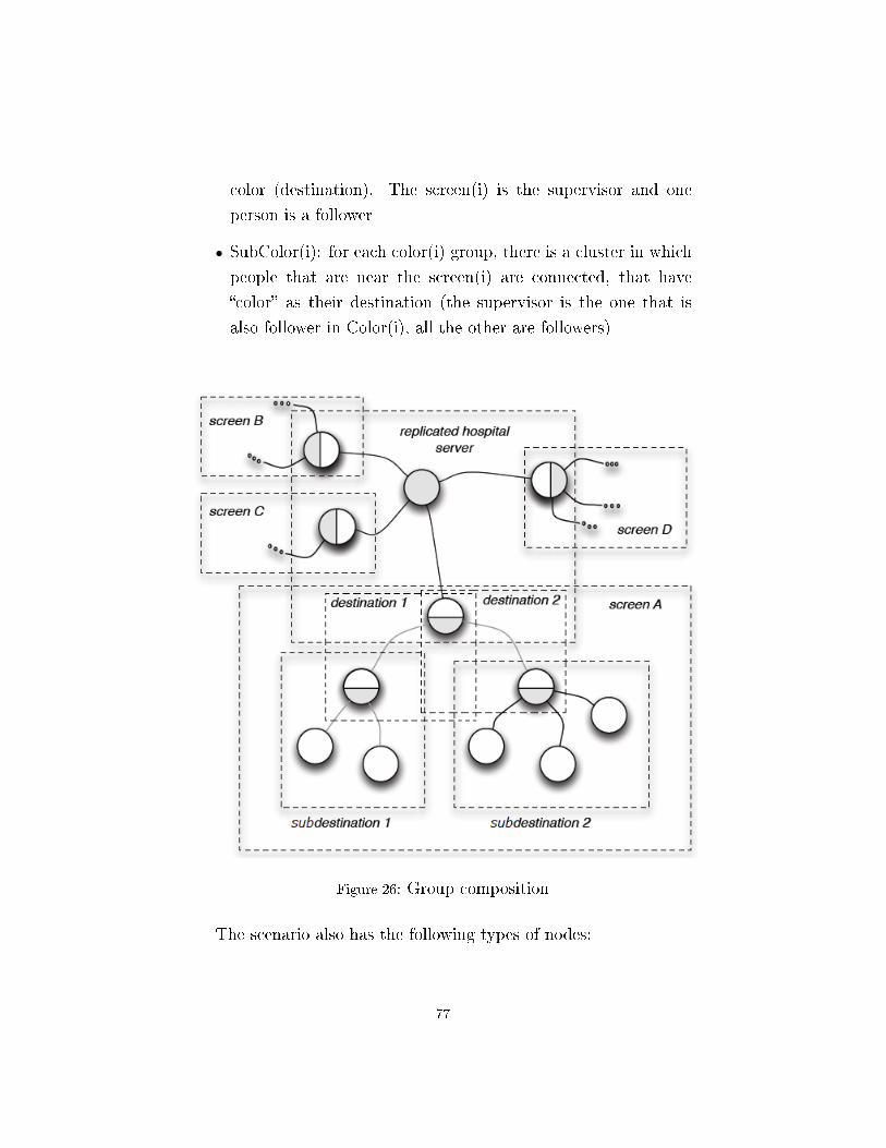
color (destination). The screen(i) is the supervisor and one
person is a follower
• SubColor(i): for each color(i) group, there is a cluster in which
people that are near the screen(i) are connected, that have
�color� as their destination (the supervisor is the one that is
also follower in Color(i), all the other are followers)
Figure 26: Group composition
The scenario also has the following types of nodes:
77

• the Hospital's server: that is the supervisor of the Screen's
group; it is replicated for fault-tolerance
• Screen: is a screen, and it has the follower role for the Screen's
group, and the supervisor roles for all groups Color(i) that are
activated by the screen
• Human: is a person, without distinction between sta�, visitor
and patients, because this distinction is made by the destina-
tion. Human can be a follower in group Color(i), and both a
supervisor and a follower in group SubColor(i)
5.2 Siafu
The �rst simulation was made using Siafu, an open-source context-
simulator written in Java. Siafu provides models for agents, places
and the context, and by altering these values we can in�uence the
scenario.
For the simulation of the hospital scenario, I mapped a hypo-
thetical �oor plan, in which the signi�cant places, those used as
destinations for the test, are two access point (that are identi�ed
by the GREEN color), a laboratory for blood's analysis (this des-
tination has the RED color), a room for radiology (BLUE color)
and, �nally, the physiotherapy room (which destination's color is
YELLOW). There are also six screens placed at six crossing corri-
dors. For this simulation I used a single PC (Intel core i7 with 8
GB of RAM), so all the connections are on the local network, and
communication is performed using the UDP protocol.
I created the screens group (�SCREEN�), in which the hospi-
tal's server acts as a supervisor and the six screens act as follow-
ers. Each screen is also the supervisor of four local groups, one
for each possible destination (�RED0�, �BLUE0�, �GREEN0�, �YEL-
LOW0�, ..., �RED5�, �BLUE5�, �GREEN5�, �YELLOW5�). Each of
78

these groups has only one person as its follower. This person cre-
ates the corresponding subgroup in which he is the supervisor and
all the other people, with the same direction and near the same
screen, are followers (�SUBRED0�, �SUBBLUE0�, �SUBGREEN0�,
�SUBYELLOW0�, ..., �SUBRED5�, �SUBBLUE5�, �SUBGREEN5�,
�SUBYELLOW5�). The groups are therefore 1 for the screens, 4 for
each screen, and a subgroup for each group created by the screen,
in total: 1 + 4*6 + 4*6 = 49. however the subgroups, are created
only when there is a person near a screen that has to go to that des-
tination. So, there were 25 groups always active, and other 24 that
were created and destroyed according to the position of the people
in the map.
The nodes are:
• 1 hospital's server (with one connection)
• 6 screen (with 5 connection for each screen, for a total of 30)
• 50 human (with one active connection for each, except for those
that are also in the color's group created by the screen, and that
can be, maximum, 24).
The total number of nodes that there are in this experiment is 57,
with a maximum of 1 + 30 + 74 = 105 active connections at the
same time.
In this simulation, the number of people entering the hospital
depends on the time of day, like in a real case. They enter using
one of the two access point, with a destination that is assigned in
a random way. Once that a person reaches his destination, a new
destination is assigned, until he leaves the hospital.
During the setup of the environment, the screen's group is cre-
ated, and as soon as a screen joins it, it gets information about the
general route from the hospital's server. At the same time, each
79

screen creates its color groups, and waits for people to arrive. When
a person is near a screen, he/she tries to connect to the color sub-
group of his destination. If he/she is connected as a follower, he/she
asks his/her supervisor for information about the path. Otherwise,
if he is connected as a supervisor (and so he is the creator of the
subgroup), he/she tries to connect to the color group of his/her des-
tination, and then asks the screen that is the supervisor in the group
about the path. When a person leaves the area near the screen, he
disconnects from the screen's network. If it was the supervisor of
the subgroup, an election between the other people in the group
takes place. As a consequence, each screen only needs to supervise
a small group of representatives to be able to manage high-volumes
of people.
I have also added an obstacle in one corridor, that it is activated
manually. This way is possible to see if the system can promptly
react to guarantee the safety of the people. The screens have the
task of monitoring the corridors in search of obstacles, and of noti�es
central server, so that it can send the new path for each destination
to all screens.
The simulation shows that people that enter with no knowledge
about the route and disposition of the rooms, are able to reach
their destination following only the instructions given by the screen,
minimizing their waiting time, even when an obstacle appears.
A video clip of this simulation is available on GoogleCode, to-
gether with the source code.
This test shows that A3JG can be used in this kind of scenario,
but, in order to understand its performance, I have other worst case
scenario test. In these scenarios all the people arrive at the same
screen, and with the same needs.
80

Figure 27: Siafu screenshot
5.3 Worst case scenario
In this test we only consider one screen, and all the people that
enter the system have the same destination. Like in the Siafu sim-
ulation, the system must ensure e�ciency and safety, so e�cient
message exchanges must be guaranteed.
The groups created in this test are:
• Color: the groups created by the screen, also behaves as their
supervisor. Since this is a worst case scenario, here there are
four di�erent color/destination (�RED�, �BLUE�, �GREEN�,
�YELLOW�)
• SubColor: these are the groups that are created when a person
81

is near a screen. Since all the people have the same direction,
we have only one group (�SUBRED�)
The number of groups is 5; three of them will be practically empty
since all the people will have the same direction. The �SCREEN�
group isn't created because, in this test, We assume that the screen
already knows the path for each destination, and that no obstacle
will appear in the environment.
For this test I used 5 PCs: one with an Intel Core i7 and 8 GB
of RAM, three with Intel Core 2s and 4 GB of RAM and one with
an Intel Core i5 and 4 GB of RAM. The �rst PC hosted the screen.
The PCs were connected in LAN through a wi� router, and the
messaging is achieved using the UDP protocol.
The test is made up of two phases.
5.3.1 Phase 1
Phase 1 evaluated how A3JG performed in evaluating the nodes
�tness functions. To obtain the best result from the election process,
and to reach all the safety goals, we need to be able to �nish the
election chores. This would allow more nodes to participate in the
election process, ensuring the best possible choice was made.
The ElectionManager class was modi�ed so that when a supervi-
sor leaves its group, the election manager collects a timestamp when
the �rst message is sent to the followers (START), a timestamp for
when the last write into the ReplicatedHashMap (LAST_MSG) oc-
curs, and a timestamp for when the last election request message is
sent to the followers (END).
The number of messages sent depends, obviously, on the number
of nodes in the system. So, if N is the number of nodes, the messages
sent for the election are:
82

• 1 message from the election manager for each follower request
their �tness function (N messages)
• 1 update of the ReplicatedHashMap for each node after each
update (N2 messages)
• 1 noti�cation message after the electionTime has elapsed for
each node (N messages)
If the election starts at time t = 0, and the electionTime ends at
time t = te, between 0 and te we sent N + N2 messages; while after
te we send N more messages. In total, in the entire process, the
number of messages that are sent is:
N + N2 + N = 2N + N2
To save time during each update on the map to determine how
many �tness function are considered by the election manager, it was
necessary to send this timestamp from each node to the manager
in order to have synchronized information of the entire process, so
between 0 and te, other N messages are sent, but this allow us to not
underestimate the time necessary for the entire process. However,
the binding value is given by the N2.
I used the 5 PCs described previously, to simulate the scenario
with increasingly high numbers of people near the screen. I started
with 1 person per each screen at the �rst step, and went up to 40
people per screen in the fourteenth test.
The election policy was to use only 1 attempt to �nd the new
supervisor (so all the new nodes that enter the group during the
election are not taken into account), and 1 second was the allowed
election time.
This simulation was done in two di�erent situations:
83

1. Stable: in this case, during the election, no node tried to join
or leave the group.
2. Unstable: this is the more realist case. The people are mov-
ing around the screen without a de�ned pattern, so during an
election nodes can join or leave the group freely.
Once I captured all the data, I calculated the time between the
beginning of the election and the last save to the RHM (S - LM)
and the time between the beginning and the end of the election (S
- E). Table 1 illustrates the result for the stable case.
In the unstable case, each person can stay in the group from 19
to 48 seconds (the value is assigned randomly) and when one leaves
the group, after two seconds it rejoins it. Table 2 shows the results
in this case.
The two diagrams in �gures 28 and 29 show a comparison between
the results obtained in the two di�erent cases.
From the diagram in �gure 28, it is possible to notice that, in the
stable situation, until the number of people is under 100, the time
(in milliseconds) to complete the data sending is in the same order
of magnitude. Beyond 100 people, the value increases exponentially.
Moreover in the unstable version, the values for cases in which there
are less than 100 nodes have the same order of magnitude. In partic-
ular, the value obtained with 5 people is the same in the two cases.
For all the other steps, the values obtained in the unstable case are
much bigger. In particular there are nodes that, in situations with
more than 100 nodes, are not able to return their �tness value in
less than 1 seconds (7 nodes out of 125 for the 5.6%, 9 out of 150
for the 6%, and 14 out of 200 for the 7%).
In the step with 200 nodes, 40200 messages are sent in the �rst
phase of the election (before t = electionTime). Considering the
stable case, in which only messages regarding the election itself are
84
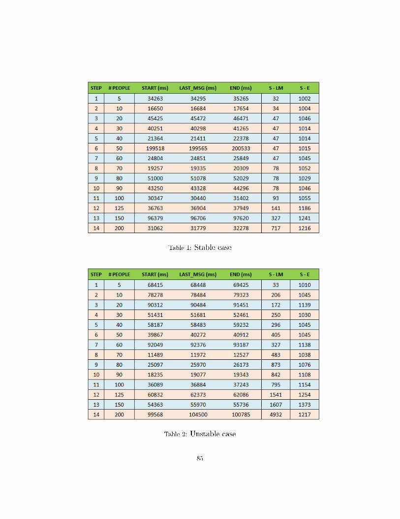
Table 1: Stable case
Table 2: Unstable case
85

Figure 28: S - LM diagram
Figure 29: S - E diagram
86

sent, and where the maximum message size is 4KB (due to the
size of the RHM), we need a network capable of sending 157 MB/sec.
The diagram in �gure 29 shows the total time necessary for the
entire election at each step. One second of this time is due to the
election time. Also it is possible to notice that the best results are
obtained with less than 100 nodes, and that the high values in the
unstable case, for steps over 100 node, are caused by the increasing
message tra�c due to that are not able to send their �tness value
in time.
5.3.2 Phase 2
Phase 2 evaluated A3JG's performance using di�erent strategies
for the election process. In fact, A3JG allows developers to im-
plement di�erent policies; they are not forced to use the election
manager with its preset default values.
Once again the groups that are created are 4(the four possible
direction), and there is 1 subgroup for the red direction, for a total
of 5 groups. The number of active nodes is 41 (1 is the screen, and
40 people that cross the area).
The values that can be modi�ed manually are the number of
attempts that take place and the election time, that is the time that
the election manager waits before choosing the new supervisor. In
particular, the developer must also implement the �tness function,
which is the core of the election policy.
For the test, I've compared four di�erent strategies:
• Case A: maxAttempt = 1, electionTime = 1 sec, �tness func-
tion that chooses the person that will stay in the group for the
most time.
• Case B: maxAttempt = 3, electionTime = 1 sec, �tness function
that chooses the person that will stay in the group for the most
87

time.
• Case C: maxAttempt = 1, electionTime = 1 sec, �tness function
that chooses the new supervisor randomly.
• Case D: maxAttempt = 3, electionTime = 1 sec, �tness func-
tion that chooses the new supervisor randomly.
With these con�gurations, it is possible to compare how di�erent
choices a�ect the result. For all four cases I set 1 second as the
election time because, in the environment, I need the election process
to �nish as quickly as possible.
I tried each case three times. In particular, each simulation had
a duration of �ve minutes and each person could be connected to
the screen for a time between 19 to 48 seconds, and after that one
leaves the group, he must wait 2 seconds before rejoining the group.
The results of my tests are shown in Table 3. The �rst column
is the case, the second is the total number of supervisors that were
activated (one is the �rst that arrives to the screen and he is ac-
tivated as supervisor without election), then there is the medium
time spent in the election process. The fourth column is the total
time spent without an active supervisor, and the last column is the
average life time.
Comparing the values between cases A and B, and cases C and
D, couples that have the same �tness function but di�erent number
of attempts, we can see that cases B and D spend more time without
coordination. However, the number of elected supervisor is smaller.
Therefore, in situations in which the recovery process is critical, it
is preferable to have a greater number of attempts.
88

Table 3: Comparison of strategies
Instead, comparing cases A and C, and cases B and D, which
use di�erent �tness functions, the results show that a good �tness
strategy greatly reduces the number of performed elections. It is
an important feature that must be implemented in the best way
possible to improve the general performance.
5.4 How can we improve?
From these tests, it is clear that the main limiting factor is the net-
work. It's necessary, �rst of all, to have a network that can support
the system and its workload. Unfortunately it's not always possible
to have a good network. Some tricks can be used, however, when
the situation is critical. For example, if we consider the hospital, in
which people join the group to set the information about their desti-
nation, we can improve the performance by disconnecting a follower
as soon as he gets the information he/she needs. This way, if there
are 200 people near the screen, the number of active connections
remains lower, since we only need to connect the supervisor and the
89

few people that just arrived near the screen.
Another possibility is to use more groups, so that when there
is an election, a lower number of followers will participate in the
process, and thus the tra�c on the network will be reduced.
There is also some work that can be done on A3JG to improve its
performance. For example, future work could develop a dedicated
communication network that replaces JGroups. This substitution
can improve the A3JG's capacity because now it is using the Repli-
catedHashMap of JGroups, but this feature is not guaranteed to
operate well, and it also increases the size of the messages during
the election. In fact, for the moment, the RHM is used to achieve
di�erent characteristics of A3JG, but all this can lead to excessive
slow down in the election process. So, in the new connection and
communication substrate, it should be possible to distinguish the
di�erent areas in which the map is currently being used, so that
di�erent elements of the network.
Future work should also consider the development of a MAPE
control loop that will complement (or replace) the current coordi-
nation process, and which may provide better tools for managing
the supervisor, and consequently the followers. In fact, for the mo-
ment the control cycle does not have distinct phases, and this may
require the developer to create a control part, with probable lower
performance. However, inserting the MAPE control loop within in-
dividual supervisors (who seem to be the most suitable entity), we
should also be careful to not tie the overall coordination of the sys-
tem to the individual groups. If this should happen a single group
could cause delays to the whole system.
90
6 Conclusion
Research on self-adaptive systems started about twenty years ago,
and in these years many solutions and ideas have been proposed. A-
3 is an innovative solution for the realization of distributed systems
with a high number of components that can freely join and leave the
system, and where the coordination and management requirements
are very strong. A-3 proposes the use of groups to de-centralize the
management of the nodes, so that the designer can concentrate on
the coordination of elements that are less dynamic. This also allows
nodes to move freely; in fact, individual entries and exits do not
cause problems for the general management of the system.
This work presented A3JG, a Java-based implementation of A-3,
that allows distributed nodes to collaborate to reach a common goal
using the A-3 style. It allows the creation of groups, and the policy
of grouping can be freely decided by the developer of the application.
Each node can assume a role in each group in which it can work,
and for each group an entity can be a supervisor (only one for each
group) or a follower. These two roles are obtained in the middleware
extending the A3JGSupervisorRole and A3JGFollowerRole classes.
Thanks to these two, the developer is able to use all the features
of A-3, such as di�erent types of message exchange on the election
process.
This thesis presented several tests to verify the actual usefulness
of A3JG as a middleware. In particular, these tests focused on the
realization of a self-adaptive hospital environment, in which people
91
are guided inside the building to reach their destinations e�ciently
and safely. In an environment such as a hospital, each day thou-
sands of people between sta�, patients and visitors that move inside
it, and if each of these represents a node in our network, a central-
ized management is not able to ensure crucial requirements such as
security.
The �rst test, showed how systems that use A3JG are able to
easily manage the task of providing the directions and guiding people
through the corridors without problems. Even in the case in which
an accident occurs in a corridor, entities predisposed to monitor
the environment for possible dangers are able to notice the problem
immediately and report it to the server so that the hospital can
adapt its paths to ensure the safety of persons.
The second test was designed to measure the performance of the
system, and it concerned on the worst case scenario, given that the
requirements can be very stringent as when human lives are at stake.
From this simulation, it was clear that a �rst limit, which is not eas-
ily surmountable, is given by the capacity of the network. However
I have proposed possible solutions to be able to operate also in these
conditions. The tests also emphasized the need to work on A3JG's
connection-level and node communication capabilities, in such a way
to have a network designed speci�cally for its characteristics. This,
in turn, should allow us to reduce the tra�c generated by message
exchanges, and to improve its performance.
Finally, it was shown that the designer's choices can greatly a�ect
the overall performance of the system. In fact, the developer is
required to provide some details on how to evaluate the nodes during
election, enable the system to recover a supervisor when it leaves the
network. From the tests I noticed that when the developer uses an
optimal strategy for assigning the �tness value, and he �ts correctly
the parameters of the election manager, this can signi�cantly reduce
92
the periods in which a group remains without a guide.
As for future work, there is the need to correctly insert MAPE
control loops inside the supervisor, providing even simple methods
to the developer, so that through these he/she can organize the
coordination within the group. A problem can be given by the
possibility of a node to join more than a group, and then to create
an information exchange between these groups. In fact, must be
avoid that the slowing down of the MAPE loop of a shared node
can be propagated within the other groups, and then that the overall
coordination of the system is slowed down.
93

References
[1] L. Baresi and S. Guinea. A-3: an Architectural Style for Coordinating Dis-
tributed Components. In WICSA, 2011.
[2] S. Guinea and P. Saeedi. Coordination of Distributed Systems through
Self-Organizing Group Topologies. In SEAMS, 2012.
[3] M. Salehie and L. Tahvildari. Self-adaptive software: Landscape and re-
search challenges. In TAAS, 2009.
[4] P. Kruchten. The �4+1� View Model of Software Architecture. In IEEE
Software, 1995.
[5] M.M. Gorlick and R.R. Razouk. Using Weaves for Software Construction
and Analysis. In ICSE, 1991.
[6] R.N. Taylor et al. A Component- and Message-Based Architectural Style
for GUI Software. In ICSE, 1995.
[7] J. Magee, N. Dulay, and J. Kramer. Regis: a Constructive Development
Environment for Distributed Programs. In Distributed Systems Engineering,
1994.
[8] P. Oreizy et al. An Architecture-Based Approach to Self-Adaptive Soft-
ware. In IEEE Intelligent Systems, 1999.
[9] H. Gomaa and M. Hussein. Dynamic Software Recon�guration in Software
Product Families. In Software Product-Family Engineering, 2003.
[10] D. Garlan, S.-W. Cheng, and B. Schmerl. Increasing System Dependability
94

through Architecture-based Self-repair. In Architecting Dependable Systems,
2003.
[11] M.J. Hawthorne and D.E. Perry. Exploiting Architectural Prescriptions
for Self-Managing, Self-Adaptive Systems: A Position Paper. In WOSS, 2004.
[12] J. Kramer and J. Magee. Self-Managed Systems: an Architectural Chal-
lenge. In Future of Software Engineering, 2007.
[13] D. Weyns and T. Holvoet. An Architectural Strategy for Self-Adapting
Systems. In SEAMS, 2007.
[14] J.C. Georgas, A. van der Hoek and R.N. Taylor. Using Architectural Mod-
els to Manage and visualize Runtime Adaptation. In IEEE Computer, 2009.
[15] S.-W. Cheng, D. Garlan and B. Schmerl. Stitch: A Language for Architectural-
based Self-Adaptation. In Journal of Systems and Software, 2012.
[16] B.H.C. Cheng et al. Software Engineering for Self-Adaptive Systems: A
Research Roadmap. In Software Engineering for Self-Adaptive Systems, 2009.
[17] JGROUPS home page, http://www.jgroups.org/
[18] SIAFU home page, http://siafusimulator.sourceforge.net/
95