seismic performance of deep basement walls - … papers/taiebat 194.00_.pdf · seismic performance...
TRANSCRIPT
6th International Conference on Earthquake Geotechnical Engineering 1-4 November 2015 Christchurch, New Zealand
Seismic Performance of Deep Basement Walls
E. Amirzehni1, M. Taiebat2, W.D.L. Finn3, and R.H. DeVall4
ABSTRACT This paper reports on continuation of an ongoing research at the University of British Columbia
(UBC) on seismic design of basement walls. The current state of practice for the seismic design of basement walls in British Columbia is based on the Mononobe-Okabe (M-O) method, using a Peak Ground Acceleration (PGA) mandated by the National Building Code of Canada (NBCC). Despite the absence of compelling damage or failure due to seismic earth pressures in the past earthquakes, the Structural Engineers Association of British Columbia initiated a task force to review the current seismic design procedures for basement walls. For this purpose a series of dynamic nonlinear soil-structure interaction analyses were recently conducted to evaluate the seismic performance of typical 4-level basement walls designed based on the state of practice in Vancouver. It was shown that under the code mandated demand the wall designed for 50-60% PGA results in a satisfactory performance in terms of drift ratio. This paper presents the recent extensions of the study to deeper basement walls founded on a different soil profile. Also a more representative nonlinear hysteretic model is used to characterize the hysteretic stress-strain response of soil. The results provide further evidence for evaluating the recommended fraction of code mandated PGA that may be used with the M-O method for acceptable seismic performance of basement walls.
Introduction
The seismic response of basement walls is a complex soil-structure interaction problem that depends on many different factors such as the nature of the input motion, dynamic response of the backfill soil, and flexural response of the wall. The current state of practice for seismic design of basement walls in the United States (Lew et al. 2010; Lew 2012) as well as in British Columbia (DeVall et al. 2010) is generally based on the studies of Okabe (1924) and Mononobe and Matsuo (1929) and their interpretations by Seed and Whitman (1970), which is generally known as the Mononobe–Okabe (M–O) method. In this limit-equilibrium force method, the earthquake thrust acting on the wall is a function of the Peak Ground Acceleration (PGA). The seismic hazard level in the 1995 edition of the National Building Code of Canada (NBCC, 1995) had a probability of exceedance of 10% in 50 years, with the corresponding PGA of 0.24g for Vancouver. The more recent editions of the NBCC (2005, 2010) mandate a considerably
1PhD Candidate, Department of Civil Engineering, University of British Columbia, Vancouver, Canada, [email protected] 2Associate Professor, Department of Civil Engineering, University of British Columbia, Vancouver, Canada, [email protected] 3Emeritus Professor, Department of Civil Engineering, University of British Columbia, Vancouver, Canada, [email protected] 4Senior Consultant Structural Engineering, Read Jones Christoffersen Ltd., Vancouver, Canada; [email protected]

different seismic hazard level with probability of exceedance of 2% in 50 years, which leads to almost doubling the PGA (0.46g). The current design PGA leads to very large seismic forces that make the resulting basement walls more expensive. Despite the absence of compelling damage or failure due to seismic earth pressures in the past earthquakes (Lew et al., 2010), the Structural Engineers Association of British Columbia (SEABC) initiated a task force to review current seismic design procedures for deep basement walls in Vancouver. The main objective of this paper is to provide further evidence for evaluating the recommended fraction of code mandated PGA that may be used with the M-O method for acceptable seismic performance of basement walls (Taiebat et al., 2013, 2014). To this end two basement walls with different heights (4-level and 6-level basement walls) have been designed by members of SEABC using the current state of practice for four different fractions of the code PGA for Vancouver. Also a more representative nonlinear hysteretic soil model compared to the one used in earlier studies of the authors is used to simulate the hysteretic stress-strain response of soil. The performance of these basement walls in the term of drift ratio have been numerically studied under fourteen seismic events matched to the Uniform Hazard Spectrum (UHS) enforced by the NBCC (2010) for Vancouver. Results of the study are presented and discussed in this paper.
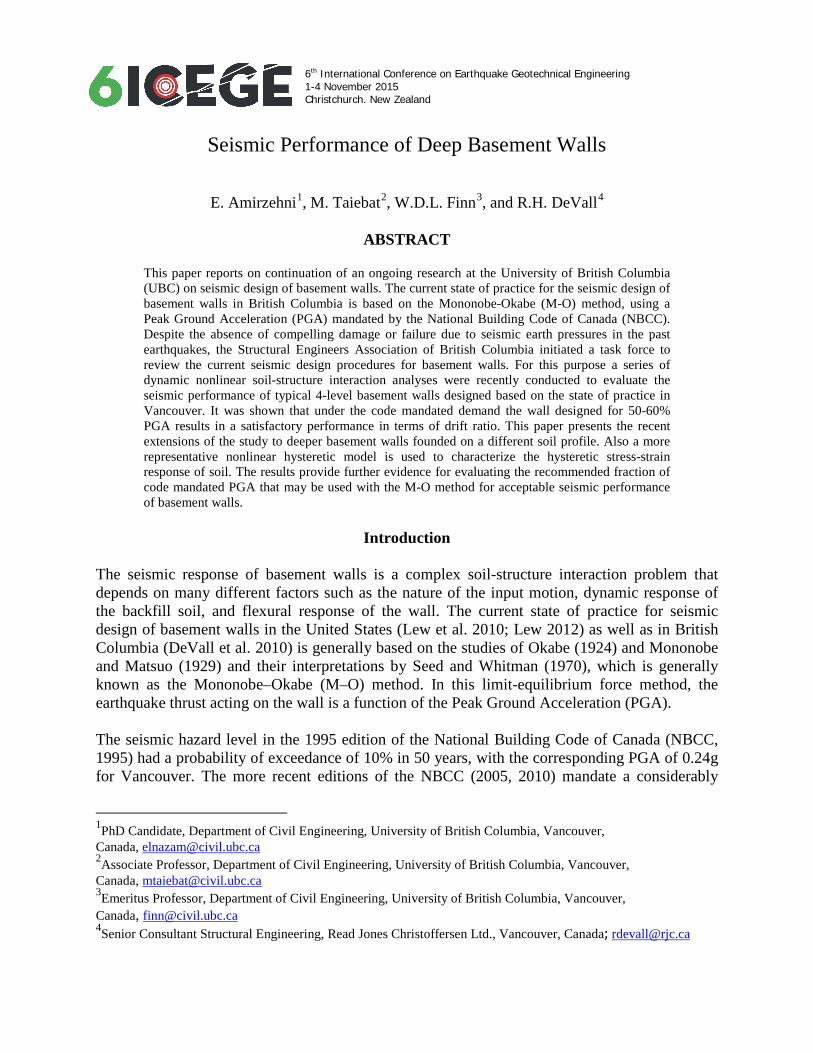
Seismic Design of the Basement Walls Seismic design of basement walls is commonly based on the active thrust calculated from the M-O method. The M-O method is a limit-equilibrium force approach, developed by modification of Coulomb's theory for active (or passive) pressures. The M-O method provides only the total lateral force during earthquake and it does not explicitly indicate anything about the distribution of lateral earth pressure from seismic events. For practical purposes, Seed and Whitman (1970) proposed to separate the total (static and dynamic) active lateral force, 𝑃𝑃𝐴𝐴𝐴𝐴 , into two components, the initial static component, 𝑃𝑃𝐴𝐴 , and the dynamic increment due to the base motion, ∆𝑃𝑃𝐴𝐴𝐴𝐴 , where 𝑃𝑃𝐴𝐴𝐴𝐴 = 𝑃𝑃𝐴𝐴 + ∆𝑃𝑃𝐴𝐴𝐴𝐴 . The static thrust, calculated from the Coulomb theory, is to be applied at 𝐻𝐻/3 from the base of the wall, resulting in a triangular distribution of pressure. As Seed and Whitman (1970) stated, most of the investigators agree that the increase in lateral pressure due to the shaking is greater near the top of the wall and the resultant increment in force acts at a height varying from 𝐻𝐻/2 to 2𝐻𝐻/3 above the base of the wall. In this study 4-level and 6-level basement walls with total heights of 11.7m and 17.1m, are investigated as shown in Figs. 1 and 2. To study the effect of the pseudo-static horizontal acceleration used in the M-O method, each basement wall was designed by the structural engineers for four different fractions of the current code PGA (0.46g). Following NBCC (2010), structural engineers used two load combinations as (1) 1.5𝑃𝑃𝐴𝐴 and (2) 𝑃𝑃𝐴𝐴𝐴𝐴 = 𝑃𝑃𝐴𝐴 + ∆𝑃𝑃𝐴𝐴𝐴𝐴 to design both 4-level and 6-level basement walls for different fractions of code PGA. Details about the calculation of moment capacities at different elevations along the height of the walls are discussed and outlined in Taiebat et al. (2014). In Consistent with the four scenarios of lateral earth pressure, corresponding to four different fractions of PGA for each wall presented in Figs. 1 and 2, four levels of yielding moment are calculated and presented in Fig. 3.
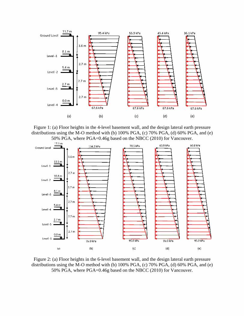
Figure 1: (a) Floor heights in the 4-level basement wall, and the design lateral earth pressure distributions using the M-O method with (b) 100% PGA, (c) 70% PGA, (d) 60% PGA, and (e)
50% PGA, where PGA=0.46g based on the NBCC (2010) for Vancouver.
Figure 2: (a) Floor heights in the 6-level basement wall, and the design lateral earth pressure distributions using the M-O method with (b) 100% PGA, (c) 70% PGA, (d) 60% PGA, and (e)
50% PGA, where PGA=0.46g based on the NBCC (2010) for Vancouver.

Figure 3: Moment capacity distribution along the height of the 4-level and 6-level basement walls designed for four different fractions of code PGA (0.46g).
Numerical Model Building
A series of nonlinear two-dimensional finite difference analyses using FLAC 2D have been conducted to model the seismic behavior of the 4-level and 6-level basement walls designed for various fractions of the NBCC (2010) PGA for Vancouver. The description of the boundary condition, construction simulation, structural and interface elements can be found in the companion paper (Taiebat et al. 2014). The 2D models of the 4-level and 6-level basement walls are presented in Fig. 4.
Figure 4: 4-level and 6-level basement wall models in FLAC 2D.
0 25 50 75 100 125 150 1750
2.7
5.4
8.1
11.7
Moment (kN-m/m)
Hei
ght (
m)
100% PGA70% PGA60% PGA50% PGA
0 25 50 75 100 125 150 1750
2.7
5.4
8.1
10.8
13.5
17.1
Moment (kN-m/m)
Hei
ght (
m)
100% PGA70% PGA60% PGA50% PGA

Constitutive model and calibration of soil parameters In consultation with geotechnical engineers, the soil properties listed in Table 1 are suggested for the two layers of soil in Fig. 4. In this table 𝑉𝑉𝑠𝑠1 is a normalized shear wave velocity based on the suggestion of Robertson et al. (1992), which is a function of the effective overburden stress.
Table 1: Soil layer material properties.
Soil layer
Density (kg/m3)
Vs1 (m/s)
Gmax (MPa)
Mohr-Coulomb UBCHYST
𝝊𝝊 Coh. (kPa)
𝝓𝝓 (°)
𝝍𝝍 (°) hrm hdfac hrf hn1 hn
1 1950 200 17-143 0.28 0 33 0 0.5 0 0.98 1.0 3.3 2 1950 400 580-885 0.28 20 40 0 0.5 0 0.85 1.5 2.0
Two layers of soil are modeled with UBCHYST soil model, which is a two dimensional nonlinear hysteretic model developed at the University of British Columbia for dynamic analysis as a FISH source (Naesgaard 2011). In order to improve the efficiency of the code, the model was converted to C++ and compiled as a DLL file (Mikola and Sitar, 2012), as used in this study. In UBCHYST the tangent shear modulus (𝐺𝐺𝑡𝑡) is a function of the peak shear modulus (𝐺𝐺𝑚𝑚𝑚𝑚𝑚𝑚) times a reduction factors which are a function of the developed stress ratio which varies throughout the loading cycle to generate nonlinear hysteretic stress-strain loops. In this model the magnitude of the stress ratio is limited by a Mohr-Coulomb failure envelope. The UBCHYST model parameters are calibrated by comparing the modulus degradation and damping curves resulting from simulations with the model to those published by Darendeli (2001). To this end, for each layer of soil presented in Table 1, an initial estimate of values was made based on a series of sensitivity analysis conducted on each parameter. Then an element cyclic simple shear (CSS) test using UBCHYST constitutive model was conducted in FLAC at different depth of the model for fifteen shear strain amplitudes, ranging from 0.0001% to 1%, to generate modulus and damping curves. The UBCHYST parameters were adjusted in a way to result the best match to the Darendeli modulus reduction and damping curves. Fig. 5 illustrates the modulus reduction and damping of the first soil layer at different confining pressures compared to the laboratory results of Darendeli. As it is shown in this figure the model overestimates the damping response at medium to large shear strains (> 0.1%). Mikola and Sitar (2012) had drawn the same conclusion and related it to the width of the hysteresis loop in the UBCHYST model.
Figure 5: Modulus reduction and damping curves estimated by FLAC at different depth of the first layer of soil using UBCHYST model.
10-4 10-3 10-2 10-1 1000
0.2
0.4
0.6
0.8
1
Shear strain (%)
G/G
max
-2 m (0.25 atm)-5 m (0.60 atm)-10 m (1.2 atm)-15 m (1.80 atm)Darendeli 0.25 atmDarendeli 1 atmDarendeli 4 atm
10-4 10-3 10-2 10-1 1000
5
10
15
20
25
Shear strain (%)
Dam
ping
Rat
io (%
)
-2 m (0.25 atm)-5 m (0.60 atm)-10 m (1.2 atm)-15 m (1.80 atm)Darendeli 0.25 atmDarendeli 1 atmDarendeli 4 atm

Ground motion selection and scaling Based on the results of de-aggregation of the Uniform Hazard Spectrum of Vancouver, searching criteria was set as the magnitude range of 6.5 to 7.5, with the closest distance of 10-30 km of the causative fault plane from the earthquake sites. Selection of the candidate ground motions was done based on the best linearly matched motions to the UHS of Vancouver for firm ground (soil class C, 𝑉𝑉𝑠𝑠 =360-760 m/s) proposed by the NBCC (2010), in the period range of 0.02-1.7 sec.
Table 2: List of selected ground motions.
Event Year Station Mag. Mechanism Vs30 (m/s) Friuli- Italy-01 1976 Tolmezzo 6.5 Reverse 424.8 Tabas- Iran 1978 Dayhook 7.35 Reverse 659.6 New Zealand-02 1987 Matahina Dam 6.6 Normal 424.8 Loma Prieta 1989 Coyote Lake Dam (SW Abut) 6.93 Reverse-Oblique 597.1 Loma Prieta 1989 San Jose - Santa Teresa Hills 6.93 Reverse-Oblique 671.8 Northridge-01 1994 LA - UCLA Grounds 6.69 Reverse 398.4 Hector Mine 1999 Hector 7.13 Strike-Slip 684.9 Also in order to eliminate the potential bias towards one specific event, no more than two ground motions were selected from the same seismic event. Table 2 shows the list of the selected seven ground motions. It should be mentioned that both Fault-Normal and Fault-Parallel components of each motion were used in this study, resulting in a total of fourteen ground motions. the selected motions were spectrally matched to the NBCC (2010) UHS of Vancouver in the period range of 0.02-1.7 sec, and then using the computer program SeismoSignal (Seismosoft, 2009) they were baseline corrected with a linear function and filtered with a band pass Butterworth filter with cut-off frequencies of 0.1 Hz and 25 Hz.
Simulation Results The maximum resultant drift ratio along the height of the wall is a parameter which is evaluated in this section. For this purpose, the recommendation of ASCE task committee on design of blast-resistant buildings in petrochemical facilities (ASCE-TCBRD, 2010) is used as the performance criteria. To the best knowledge of the authors, there is no other report on the acceptable drift ratios for constrained walls with distributed lateral loading. In this recommendation the drift ratio of a basement wall at the middle of each storey is calculated as the difference between the displacement of the wall at that level and the average displacements of the wall at the top and bottom of the storey divided by half of the storey height. The ASCE specified a low response category as “Localized component damage with moderate cost of repairs”. The response limits associated with this category for the reinforced concrete wall panels (with no shear reinforcement) is 1.7% drift ratio.

Figure 7: Average of maximum drift ratios along the height of the 4-level basement wall, designed for four different fractions of the code PGA subjected to fourteen ground motions.
Figure 8: Average of maximum drift ratios along the height of the 6-level basement wall, designed for four different fractions of the code PGA subjected to fourteen ground motions.
-1 0 1 2 3 40
2.7
5.4
8.1
11.7
Drift (%)
Hei
ght (
m)
meanmean+σmean-σ
50% PGA
-1 0 1 2 3 40
2.7
5.4
8.1
11.7
Drift (%)
Hei
ght (
m)
meanmean+σmean-σ
60% PGA
-1 0 1 2 3 40
2.7
5.4
8.1
11.7
Drift (%)
Hei
ght (
m)
meanmean+σmean-σ
70% PGA
-1 0 1 2 3 40
2.7
5.4
8.1
11.7
Drift (%)
Hei
ght (
m)
meanmean+σmean-σ
100% PGA
-1 0 1 2 3 40
2.7
5.4
8.1
10.8
13.5
17.1
Drift (%)
Hei
ght (
m)
meanmean+σmean-σ
50% PGA
-1 0 1 2 3 40
2.7
5.4
8.1
10.8
13.5
17.1
Drift (%)
Hei
ght (
m)
meanmean+σmean-σ
60% PGA
-1 0 1 2 3 40
2.7
5.4
8.1
10.8
13.5
17.1
Drift (%)
Hei
ght (
m)
meanmean+σmean-σ
70% PGA
-1 0 1 2 3 40
2.7
5.4
8.1
10.8
13.5
17.1
Drift (%)
Hei
ght (
m)
meanmean+σmean-σ
100% PGA

Figure 9: Exceedance probability of drift ratio for 4-level and 6-level basement walls designed for different fractions of code PGA.
Figs. 7 and 8 show the maximum drift ratio along the height of the 4-level and 6-level basement walls, each designed for four different fractions of code PGA, and subjected to fourteen seismic events. In these plots the mean value corresponds to the average of the maximum drift ratio from fourteen seismic events. Assuming normally distributed drift ratios, mean ± standard deviation (σ) represents the first standard deviation with 68% chance that the mean falls within the range of standard error. According to the adopted performance criterion for drift ratio, in the present problem the response of the top and bottom levels of the basement walls need careful consideration. The results of both 4-level and 6-level basement walls suggest that the performance of the walls designed for even 50-60% of the code PGA for Vancouver seem adequate. The exceedance probability of drift ratios from a certain value for both 4-level and 6-level basement walls, each designed for different fractions of code PGA is presented in Fig. 9.
Conclusions In the present study the seismic performance of the typical 4-level and 6-level basement walls, subjected to the seismic demand in Vancouver were examined. Both walls were designed according to the state of practice in Vancouver for different fractions of NBCC (2010) PGA. The nonlinear seismic performance of these walls suggest that the behavior of the top and bottom basement levels are critical. Based on the proposed acceptance criteria for drift ratio by ASCE-TCBRD (2010) one can conclude that designing the basement walls for full PGA is over conservative. This is while the behavior of both 4-level and 6-level basement walls designed for 50%–60% code PGA result in satisfactory performances when subjected to the current seismic hazard level in Vancouver with a 2% chance of being exceeded in 50 years.
Acknowledgments The authors are grateful for many constructive contributions from Dr. Ernest Naesgaard (Naesgaard-Amini Geotechnical Ltd.) and Mr. Doug Wallis (Levelton Consultants Ltd.). Support to conduct this study is provided in part by the Natural Sciences and Engineering Research Council of Canada (NSERC).
0 0.5 1 1.5 20
20
40
60
80
100
Drift (%)
Prob
abilit
y of
Drif
t Exc
eeda
nce
(%)
50% PGA60% PGA70% PGA100% PGA
4-level basement wall
0 0.5 1 1.5 20
20
40
60
80
100
Drift (%)
Prob
abilit
y of
Drif
t Exc
eeda
nce
(%)
50% PGA60% PGA70% PGA100% PGA
6-level basement wall

References
ASCE-TCBRD (2010). Design of Blast-Resistant Buildings in Petrochemical Facilities. Task Committee on Blast-Resistant Design of the Petrochemical Committee of the Energy Division ASCE. American Society of Civil Engineers, Reston, VA, USA, 2nd edition.
DeVall, R., Finn, L., Byrne, P., Anderson, D., Naesgaard, E., Amini, A., Taiebat, M., Wallis, D., Kokan, M., Mutrie, J., and Simpson, R. (2010). Seismic design of basement walls in British Columbia. Personal Communication.
Darendeli, M. B. (2001). Development of a new family of normalized modulus reduction and material damping curves.
Geraili Mikola, R. (2012). Seismic Earth Pressures on Retaining Structures and Basement Walls in Cohesionless Soils.
Itasca (2012). FLAC: Fast Lagrangian Analysis of Continua, Ver. 7.0. Itasca Consulting Group, Inc., Minneapolis.
Lew, M., Sitar, N., Al-Atik, L., Pourzanjani, M., and Hudson, M. B. (2010). Seismic earth pressures on deep building basements. SEAOC Convention Proceedings, Structural Engineers Association of California, 1-12.
Lew, M. (2012). Recent findings on seismic earth pressures. The Structural Design of Tall and Special Buildings, 21, S48-S65.
Mononobe, N. and Matsuo, H. (1929). On the determination of earth pressures during earthquakes. Proceedings of World Engineering Conference, 176-182.
Naesgaard, Ernest (2011). A hybrid effective stress–total stress procedure for analyzing soil embankments subjected to potential liquefaction and flow.
NBCC (1995, 2005, 2010). National Building Code of Canada. Institute for Research in Construction, National Research Council of Canada, Ottawa, ON, Canada.
Okabe, S. (1924). General theory on earth pressure and seismic stability of retaining walls and dams. Proceedings of the Japan Society of Civil Engineers, 10(6), 1277-1330.
Robertson, P.,Woeller, D., and Finn,W. (1992). Seismic cone penetration test for evaluating liquefaction potential under cyclic loading. Canadian Geotechnical Journal, 29(4), 686-695.
Seed, H. and Whitman, R. (1970). Design of earth retaining structures for dynamic loads. ASCE Specialty Conference on Lateral Stresses in the Ground and Design of Earth Retaining Structures, Vol. 1, ASCE, 103-147.
Seismosoft (2009). “SeismoMatch version 1.0.3" and “SeismoSignal version 4.1.2".
Taiebat, M., Finn, W., Ahmadnia, A., Amirzehni, E., and Ventura, C. (2013). Seismic evaluation of existing basement walls. In Computational methods in earthquake engineering. Computational Methods in Applied Sciences. Edited by M. Papadrakakis, M. Fragiadakis, and V. Plevris. Springer, the Netherlands. Vol. 30, pp. 177–196.
Taiebat, M., Amirzehni, E., and Finn, W. D. L. (2014) “Seismic design of basement walls: evaluation of the current practice in British Columbia”, Canadian Geotechnical Journal, vol. 51, no. 9, pp. 1004-1020.