seismic damage and failure analysis of arcch dam …authors should be written like a.mehmet and...
TRANSCRIPT

SEISM
ABSTRA
In thireservoirLagrangmodels considerthe analycomplexmassivelDifferendamage subjectedmodes asystem wdamage.Keyworddamping
1 INTRO
Variouresponsecompresconcretethrough DruckerChina. Hresponse
One oconcreteparametedevelopmapplied t
In thisseismic 1 Doctor, 2 Professo3 Professo4 Professo
MIC DAMDIFFE
ACT
s study, a rr system bae multiplier of concrete ring radiationysis model anx in the daly parallel co
nt material mmodel and
d to the Wenare got by uswhich has be
ds: arch damg; parrallel co
ODUCTION
us models he of arch damssion to anae dams consia shaking ta−Prager ela
Hariri-Ardebe of KARADof the most e and rock ers are charment of micrto the failures paper, due damage res China Institu
or, China Instior, China Instior, China Insti
MAGE ANERENT M
Shengsh
relatively cosed on finitmethod con
and rock con damping dund solving m
am-foundatioomputation b
models consiDrucker-Pra
nchuan earthsing differeneen simulated
m; damage momputation
N
have been dm. Cervera elyze the seiidering heterable test. Paastoplastic mili et al4. us
DJ arch dam iimportant ais the init
racterized byrocracks whie of concrete
to the compsponse of a
ute of Water Ritute of Wateritute of Wateritute of Water
ND FAILMATERIA
an Guo1, D
mplete nonle element mnsidering coonsidering daue to energy
method couplon-reservoir based on the dering foundager elastophquake is taknt material md by using da
model; seism
eveloped duet al1. used aismic damagrogeneity natan et al3. usedmodel to comed the coaxiin Iran. spects in theiation and
y the evolutiich eventualland rock is s
plexity of dynarch dam u
Resources and r Resources anr Resources anr Resources an
1
LURE ANAL MOD
eyu Li2, Jin
linear dynammethod in thontraction joam and foun
y dissipationling contact psystem anddomain decodation are u
plastic modeken as an exmodels of fouamage mode
mic response
uring the recan isotropic ge of an arcture of the cd the extendmpare the seial rotating s
e failure of propagation
ion of the dly form into suitable and
ynamic propeusing differe
Hydropower nd Hydropownd Hydropownd Hydropow
NALYSISELS OF F
n Tu3, Houq
mic analysis he time domoint openingndation, andto the far fieproblem andd enormousomposition msed for coml. The studyample. The rundation, anl for dam an
e; contact fo
cent years fodamage mod
ch. Zhong econcrete matded finite eleeismic damasmeared crac
non-homogen of microcdecreasing omacroscopicrealistic.
erty of rock ment material
Research, Beier Research, Ber Research, Ber Research, B
OF ARCFOUNDA
un Chen4
model of amain is prese
and closingd viscous-spreld foundatiod nonlinear m computatio
method is intmparison, incl
y of Shapai result showsd the damagd foundation
orce model;
or modeling del which alet al2. studieterial and thement, plasticage of Dagack approach
eneous quasicracks. Macrf strength anc crack. Ther
mass, to expl models fo
ijing, guoss@Beijing, lideyuBeijing, tujin@Beijing, chenh
CH DAM WATION
arch dam-fouented. In thig, nonlinear ring boundaron are includmaterial modon work is troduced accluding elastii arch dam s that differege of dam-fon is close to t
foundation
the seismicllows for tened seismic fe model wasc damage mangshan arch
to study the
i-brittle matroscopic mend stiffness refore, dama
plore the effeor rock mas
@iwhr.com [email protected] @iwhr.com [email protected]
WITH
undation-is model,
material ry model
ded. Since del is very
needed, cordingly. ic model, in China nt failure
oundation the actual
radiation
c damage nsion and failure of s verified odel, and h dam in e seismic
terial like echanical with the
ge model
ect on the ss, some
m

2
comparative investigations are taken. The seismic damage process of Shapai dam-foundation system is investigated by using damage model applied to dam-foundation system. As comparative studies, the seismic damage process of dam-foundation system is investigated by using damage model for dam, using Drucker-Prager elastoplastic and elastic model for rock mass. Since the computation is enormous, parallel computation is introduced in this paper and all computing work is completed by the parallel finite element program developed by China Institute of Water Resources and Hydropower Research.
2 Time domain dynamic equation
Dynamic equation after finite element discretization:
MU CU KU F (1)
Where, M , C and K are the mass, damping and stiffness matrixes respectively,and F , U , U andU are the load, acceleration, velocity and displacement vectors respectively. For large scale nonlinear dynamical calculations, the decoupled explicit integration algorithm is more efficient. Thus, this paper adopts the decoupled explicit numerical integration format which combines the center differential and unilateral differential method as:
n n 1n dt
U UU
,
n 1 n n 1n 2
2
dt
U U U
U. (2)
The discrete dynamic equation at time step n+1 is written as:
2 2
n 1 n n 1 n n n 1 n2 MU M U U KU C U U Fdt dt dt (3)
If the diagonal lumped mass matrix M is used, the equation is solved explicitly.
3 Foundation radiation damping
For the seismic response of the dam, since foundation is infinite with respect to the dam, the seismic analysis of dam is actually to simulate the wave propagation of the open system consisting of infinite foundation and dam, which includes both the vibration of dam generated by the input wave and the scattering wave to the foundation generated by the dam as vibration source. The energy gradually escapes as the scattering wave transmits to the foundation due to the geometric spreading and damping dissipation. In the actual calculation, it is impossible to simulate the scattered wave dissipation process of infinite foundation, and the foundation can be only taken a limited range. Theoretically, as long as the scope of foundation meets the need of 2L CT , where C is the velocity of foundation
and T is the seismic wave duration,the dissipation effect can be included. In static analysis, the foundation far away from the dam could take a larger size grid, but in dynamic analysis oversized grid could not be taken due to the limit of the wave length. Thus, if the scope of foundation is taken by
/L CT 2,considerable computing would be brought and difficulty to apply to engineering practice. If a smaller range of foundation is taken,the scattered wave which was supposed to spread to foundation would reflect back to dam and seismic response of dam would be amplified. The effect that energy spreads to foundation is equivalent to damping, so called ‘foundation radiation damping’. In order to simulate the effect of ‘foundation radiation damping’, in the context of a limited range of foundation, the concept of artificial boundary is proposed to simulate the effect of infinite foundation to near –field wave.
Global artificial boundary and local artificial boundary are two main boundaries. Global artificial boundary5,6 is based on the frequency domain and coupled equation is formed in space domain. To solve the coupled equation, cumbersome and enormous computation is needed. The nonlinearity of foundation can’t be considered due to the frequency domain. Thus, the local artificial boundary which is a decoupled method in space and time domain is proposed. The local artificial boundary includes

Authors should be written like A.Mehmet and M.Ahmet 3
displacement artificial boundary and stress artificial boundary. Transmitting boundary7 belongs to displacement artificial boundary which has second –order accuracy, but the phenomenon of numerical instability may occur and usually requires repeatedly trial. Viscous-spring artificial boundary8 belongs to stress artificial boundary, which needs to impose external force and spring-damping system on the boundary. The boundary nodes and internal nodes use a uniform format to solve and the algorithm has first order accuracy and good stability.
The viscous-spring artificial boundary is used in the present paper. This boundary condition is applied at the far –end boudanry of the foundation in 3D space given as :
n nK u C u , 1 s sK v C v , 2 s sK w C w (4)
Where and are the normal and shear tractions; u , v , and w are the displacement of normal and two shear components; u , v , and w are the velocity of normal and two shear components; nK
and sK are the spring coefficient of normal and shear components; nC and sC are the damping
coefficient of normal and shear components; K and C are given as:
n
EK
r2 ,
s
GK
r2 (5)
n pC c, s sC c (6)
Where r is the distance from wave source to boundary; E is modulus of elasticity; G is shear modulus of elasticity; is density ; pc is pressure wave velocity; sc is shear wave velocity; pc and
sc are given as:
p
(1 )
(1 )(1 2 )
Ec
,
s 2(1 )
Ec
(7)
Where is Poisson’s ratio.
4 The contact nonlinearity of contraction joints
Contraction joints are an important aspect of seismic response of arch dam. During the construction process, the placement of arch dam concrete is divided into several dam sections as a section of 20m width. After concrete cools to the steady temperature and contraction joints grouting between dam sections, dam sections combines into a whole model to resist water load. Under the static load, contraction joints work in compression. During earthquake, the arch tensile stress generated overcomes the arch compressive stress under static load and then contraction joints open. Pacoima arch dam in America has experienced the Richter 6.6 earthquake and dam itself is not damaged, but the opening and closing of contraction joints has obviously occurred. The contact nonlinearity caused by contraction joints attracts the attention of scholars.
Contact problem has clearly physical concept, mainly including opening, closing and slipping of contact surface, and easy to determine the constraint condition. The point is to get appropriate numerical solution method aiming to the discontinuous nonlinear problem.
The contact model can be divided into two categories aiming to the different treatment of constraint condition. One is contact force model based on the nonlinear boundary condition, taking Lagrange multiplier method as representative, and Lagrange multiplier represents the unknown contact force. Another is represented as penalty function. The introduction of contact stiffness into model is to meet the contact boundary constraint condition. To meet the condition of no embedding between contact surface, penalty function method needs to introduce greater stiffness. Theoretically, there still exists embedded distance, and there is a certain sensitivity to the stiffness value. In the contact force model, applying the unknown force as the contact force to the contact interface is to meet the constraint

4
condition, and there is no problem of artificially assumed stiffness. The Lagrange multiplier method is used in this paper.
The contact surface constraint condition:
a. Opening condition B A n
s
0 0
0
u u n
b. Closing condition
B A n
n 1 n 1 n 1B A B A s n
0 0
u u n
u u t u u t
c. Slipping condition
B A n
n 1 n 1 n 1B A B A s n
0 0
u u n
u u t u u t
Where, the location of point A and B is Au and Bu ; n is the direction vector from A to B; s is
shear contact force; n is normal contact force; is friction coefficient; t , n 1t is the current step and
previous step.
From (3), A M , 2 2n n 1 n n n 1 n2 F M U U KU C U U Fdt dt dt , n 1U U ,the
equation can be written as:
AU F (8)
The equation including contact force can be given as:
AU F Bλ (9)
Where, B is contact constraint matrix, λ is contact force vector.
Contact constraint equation can be given as:
T B U γ (10)
Where, γ is displacement constraint vector.
From (9) and (10), contact force equation is given as:
l Cλ DU (11)
Where lλ is contact force vector in the local coordinate system, C is flexibility matrix , DU is displace vector .C and DU are given as:
T 1 T TC TB A B T , T 1 l DU TB A F γ (12)
Where lγ is displace constraint vector in the local coordinate system, T is coordinate system transformation matrix.
The flexibility matrix of contact force equation C is full matrix due to added mass considering the effect of dynamic water pressure, normal contact force and shear contact force are coupled each other. The modified Gauss-Seidel iterative method solving normal contact force and shear contact force alternatively is used to solve the equation.

5 Damag
Dama(1) The d(2) The tis mainly(3) Resid(4) Elast(5) Durinmodulus
As shostrain. Cinitial unstress tencorrespothe corremodulusbut needcompresloading a
The dfrom mu
The y
where
respectivdamage ratio of c0.12 and
The w
Where,
is minus
ge model of
age and failurdamage proctensile strengy controlled dual deformatic modulus ang the transfs returns to th
Figu
own in FigurConcrete testinloading strands to zero, t
onding secantesponding elas recovers thed to account fssive load, thand unloadinamage mode
ulti-axial conield function
e the 1I and J
vely, and thesurface, whicompressive d 7.6810. weight factor
1
2
s, the value ch
Authors s
concrete
re of concretcess of these gth of concreby tensile stration can be and strength formation frohe initial valu
ure 1 Damage
re 1, e ing results shain, there is nthere exists at modulus chastic modulue initial valufor the residu
he increasinglng can be gotel in this papndition to unin is given as:
2J are the firs
e and arich are relateto tensile str
is given as:
; If the
hanges to ze
should be wri
te has the folquasi-brittle
ete and rock rength. caused due tdecrease wit
om tension toue, showing
evolution fund . Where
how that undno extra damaan irreversiblhanges nonlinus. When thee due to the ue deformatioly irreversiblt. er has borrowiaxial conditi
1
1F
st invariant o
re the dimensd to the ratiorengths. The
value of
ero; ˆi is eff
itten like A.Me
llowing charae materials isis much low
to not complth the evoluto compressioso called ‘un
nction of concr
e, is total sder the reciproage and the ele strain. Its nearly with s
e load changecrack closuron. Accordinle deformatio
wed the yieldion from con
1 2
13I J
of stress and s
sionless conso of equibiaxe constants
ˆ( ) σr
is positive
ffective princ
ehmet and M.A
acteristics:s the initiatio
wer than comp
etely closingtion of damagon, due to thenilateral effe
rete under uni
strain; e is eocating loadelastic moduactual apparestress, and thes from tensie, showing thng to the teston and the da
d function anncrete plastic
1 cˆ 0c
second invar
stants evaluaxial to uniaxi and for
3
13
1
ˆ
ˆ
ii
ii
e, the value r
ciple stress.
Ahmet
n and propagpressive stren
g of crack. ge. e closing of cct’.
iaxial cyclic te
elastic strain;, if the strain
ulus remain tent modulus
he apparent mion to comprhe so called t results of unamaged elast
nd the concep damage mo
0
riant of stress
ated by the inal compressir concrete are
emains same
gation of micngth, and its
crack, elastic
ensile loading
; d is damagn doesn’t excthe same. Whand the
modulus is leression, the e‘unilateral eniaxial tensiltic modulus
pt of weight odel9.
s deviator
nitial shape oive strengthsre usually tak
e; If the valu
5
crocracks. damage
c
ged ceed the hen
ess than elastic ffect’, le and under
factor
(13)
of s and the ken as
(14)
e of

After
unloadin
is 1E
The cons
ttd rd
For mult
strain ve
value an
equation
6 Paralle
The bseveral ssystems,decompo(1) The (2) The(3) The
By ovdomain dfoundatimessagin
Since decouplemodel, amodel arvelocity solution the boun
concrete is d
ng strain, its
t 01 1d E
stitutive equa
and the con
tidimensiona
ector pε . Wh
nd the constit
n is 1 d σ
el computati
asic idea of dsub-systems., and the excosition methowhole mode solution of e solution of t
verlapping thdecompositioon of overlapng between s
the mass maed equation hat each time sre updated byand acceleraof kinematic
ndary conditi
damaged, wh
stress is
p 1
ation is nstitutive equ
al system, mhen t is less
tutive equatio
pd D ε ε
ion based on
domain deco The solutionhange betweod is dividedel is divided ieach sub-mothe whole m
he district or non method anpping domaisub-models i
Fiatrix is diagohas the innatstep, the dispy exchangingation of the sc equation wion by excha
hen the strain
t 01 d E
tt 01 d E . W
E . For m
uation is σ
max is close to
than p , fro
on is 0E
.
domain dec
omposition mn of originaleen sub-systed into steps ainto several s
odel is done iodel is got bynot, domain nd non-overlin decomposis done throu
igure 2 Overlaonal, the kinee advantage
placement, veg data of the sub-model ar
with explicit innging data.
6
n under unloa
p and
Where, ttd is
multidimensio
1 d Dε .
o p and the s
om tension t
p0 . F
composition m
method is thesystem can b
ems can be aas follows: sub-models. in each partity combiningdecompositilapping domition method
ugh the relate
apping districtetic equation of parallel celocity and a related over
re got from thintegral form
ading and rel
d its correspo
s the correspo
onal system,
. When stres
strain vector
to compressio
For multidim
method
use of blockbe changed ichieved by d
tion. g the results oion method i
main decompod is Schwarz ed district, as
t between subof explicit foomputation.
acceleration orlapping distrhe new boun
mat is done w
loading does
onding appar
onding appar
the equivalen
s tends to zer
ε is the corre
on, stiffness
mensional sys
k, dividing a into the solutdata transferr
of each sub-ms divided intosition methoalternating m
s shown in Fi
-models format is deco
For the comon the boundrict, and then
ndary conditiithout iterati
sn’t exceed th
rent elastic m
rent damage
nt damage v
ro, t is clos
responding re
recovers the
stem, the con
whole systemtion of severring. Domain
model. to overlappinod. Theoreticmethod and igure 2.
oupled. Thusmputation of edary of each n the displaceions. Thus, thion, simply u
he initial
modulus
variable.
ariable
se to p .
esidual
e initial
nstitutive
m into ral sub-n
ng cal
s, the each sub-sub-ement, he updating

As shand exteand extethis sub-this sub-
Parallprocess acomputaprocessemessaginsub-modcommun
A damtested. Ttested. ATable 1.
Numbe
hown in Figuernal nodes, wernal nodes a-model is the-model. The el computatiand several sation and it ises. All messang between sdel computatnication are d
m-foundationThe whole moA multicore c
er of process
1
2
4
6
8
10
11
Slave p
Sub-mo
I
Authors s
Figuure 3, the nodwhere internare used to ee external nosolution of eion structure slave processs responsibleaging occurs slave procession. Messagidone sequent
n system withodel is dividcomputer wit
TabRunni
1
process 1 Sl
odel 1 S
Information ex
should be wri
ure 3 node disdes of each pnal nodes andexchange infodes of anothexternal node
uses a masteses. Master pe for sending between the ses and slaveing is achievtially. As sho
Figure 4 Ph 466381 noded into 1-11 th 12 CPU is
ble 1 Parallel cing time(h)
13.22
6.93
3.59
2.62
2.11
1.93
1.94
ave process 2
Sub-model 2
xchange
itten like A.Me
stribution diagpartition ared boundary nformation wiher sub-modes is not takeer-slave progprocess is a cg data to slavee master proce processes aved by blockiown in Figure
Parallel compudes, 445383 sub-models
s used. The e
computation pSp
Master proce
2
ehmet and M.A
gram in each sdivided into
nodes are soith other sub
del, and the een in this subgramming mcontrol progre processes a
cess and slavare only respoing commune 4.
utation structuelements anand the parafficiency of
performance tpeedup
1
1.91
3.68
5.05
6.27
6.85
6.81
ess
Slave proces
Sub-model
Informa
Ahmet
ub-model o internal nolving nodes,
b-models. Thexternal node-model. odel, consist
ram that doesand receivinge processes. onsible for thication that c
ure d 1399143 d
allel computaparallel com
test value Parallel
1
9
9
8
7
6
6
ss 3 Slave pr
l 3 Sub-mo
ation exchang
odes, bounda, and boundahe boundary des is the bou
ting of one msn’t participag data from s There is no he corresponcomputation
degrees of freation perform
mputation is s
l efficiency
00%
96%
92%
84%
78%
69%
62%
rocess n
odel 4
ge
7
ary nodes ary nodes nodes of
undary of
master ate in the slave
nding and
eedom is mance is shown in

7 Seismi
Shapaworld’s hstrong eawas not earthquadepartmedegrees correspoby a thorduring thparametereestablig and lon
Finite freedomnonlineaThroughdirectionshown innumber includingelastic fo
Fig
The co
0 18E
F 29G degradat
-0.
-0.
-0.
0.
0.
0.
0.
Acc
eler
atio
n/g
ic response o
ai dam is a thhighest RCCarthquake ofearthquake r
ake. Accordinent announceand PGA ran
onding accelerough inspeche earthquakers identifiedished 3 compng duration o
Figure element mo
me are 425568ar material mh the thicknesn, the grid lenn Figure 7, thof elements. g 2112 contaoundation ro
gure 6 FEM m
oncrete mate
GP a , Poiss
96 N m , Fig
tion tensile s
0 30 603
2
1
0
1
2
3
T
of Shapai arc
hree-center grC arch dam atf M=8.0. Therecording devng to the coned after the enges betweeneration have ction of the dke, it has to bd by the acceponents of thof more than
5 reestablisheodel: As show8 , 404090, a
model, so thross direction ongth of dam
he total numbThe number
act point pairck mass is ab
mesh of dam-fo
erial paramet
son ratio ure 8 and Fig
trength w
90 120Time/s
ch Dam
ravity arch st the time. O
e distance frovice at the dantour map of earthquake, tn 177gal-286exceeded de
dam site. Since reestablish
elerograms rehe artificial acn 40 minutes.
ed artificial acwn in Figure 6and 1276704,ough the heigof dam, the dis taken as 2
ber of nonliner of dam nodrs modelling bout 10-25 m
foundation sys
ters are taken
0.167 , dyn
gure 9 show th
tf and to the
150 0 3-0.3
-0.2
-0.1
0.0
0.1
0.2
0.3
Acc
eler
atio
n/g
8
structure, of 1On May 12, 2om Shapai aram site, the ef seismic intethe seismic in6gal. The seiesign values. ce no ground
hed by using ecorded at 7 ccelerogram. The seismic
ccelerograms a6, the total nu, respectivelyght directiondam is divide2m. The grid ear material
des and elem contracting
m.
stem
n as: density
namic tensile
he adjusted
e damage var
30 60 90Time/s
132m high, c2008, Wenchurch dam to thearthquake reensity and bentensity of thsmic intensit After the ea
d motion hasthe “stochasstations duri
ms for the Shac wave is sho
at Shapai damumber of noy. The dam of dam, the
ed into 11 palength of neelements is1ents is 67326joints and in
Figure 7 FE
2400 k e strength tf
function of c
riable w D
120 150-
-Acc
eler
atio
n/g
completed inuan in China
he epicenter iecording faildrock peak ahe Shapai damty of the damarthquake, nobeen recordtic finite fauing the earthqapai dam siteown as Figure
m site (from Zhdes, elementand near fielgrid length o
arts. Accordinear foundatio82867, whic
6 and 58757 nduced joints
EM mesh of no
3kg/ m , origin
0 4.3MPacracking disp
.
0 30 6-0.2
-0.1
0.0
0.1
0.2
n 2006, was ta was attackeis 36 km. Sinled to obtain acceleration am site rangem site and theo damage wa
ded at the damult method” aquake. Fig. 1
e with PGA oe 5.
hang Cuiran) ts, and degreld is modeledof dam is takng the cross
on is about 3mch is 45% of respectively
s. The elemen
onlinear elem
nal elastic m
a , fracture en
placement to
60 90 120
Time/s
the ed by the nce there during PGA the s 8 - 9 e as found m site and 13 is the of 0.262
es of d by ken as 2m. river
m. As the total
y, nt size of
ents
modulus
nergy
o the
150
Authors should be written like A.Mehmet and M.Ahmet 9
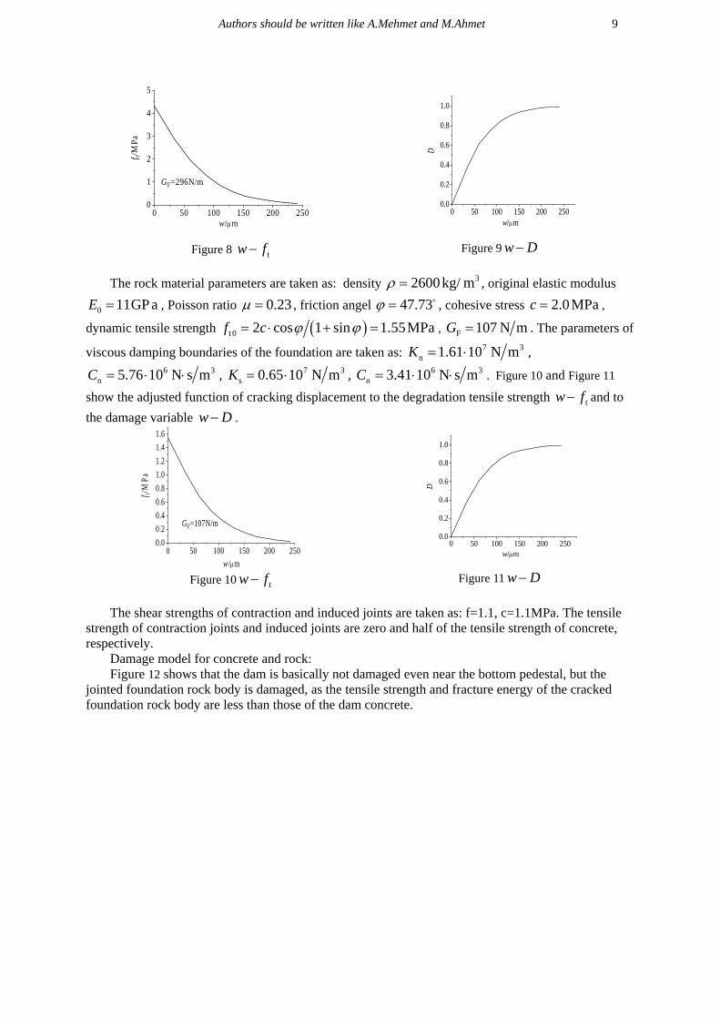
Figure 8 tw f Figure 9 w D
The rock material parameters are taken as: density 32600kg/ m , original elastic modulus
0 11GP aE , Poisson ratio 0.23 , friction angel 47.73 , cohesive stress 2.0MPac ,
dynamic tensile strength t 0 2 cos 1 sin 1.55MPaf c , F 107 N mG . The parameters of
viscous damping boundaries of the foundation are taken as: 7 3n 1.61 10 N mK ,
6 3n 5.76 10 N s mC , 7 3
s 0.65 10 N mK , 6 3n 3.41 10 N s mC . Figure 10 and Figure 11
show the adjusted function of cracking displacement to the degradation tensile strength tw f and to
the damage variable w D .
Figure 10 tw f Figure 11 w D
The shear strengths of contraction and induced joints are taken as: f=1.1, c=1.1MPa. The tensile
strength of contraction joints and induced joints are zero and half of the tensile strength of concrete, respectively.
Damage model for concrete and rock: Figure 12 shows that the dam is basically not damaged even near the bottom pedestal, but the
jointed foundation rock body is damaged, as the tensile strength and fracture energy of the cracked foundation rock body are less than those of the dam concrete.
0 50 100 150 200 2500
1
2
3
4
5
f t/M
Pa
w/m
GF=296N/m
0 50 100 150 200 2500.0
0.2
0.4
0.6
0.8
1.0
D
w/m
0 50 100 150 200 2500.0
0.2
0.4
0.6
0.8
1.0
1.2
1.4
1.6
f t/M
Pa
w/m
GF=107N/m
0 50 100 150 200 2500.0
0.2
0.4
0.6
0.8
1.0
D
w/m
‐Dt

Damadamaged
age model for near the botto
Figure 13
Upstream da
Downstream
Upstream
Downstre
Figuconcrete and
om pedestal an
Damageable
m surface
m dam surface
m dam surface
eam dam surfac
ure 12 DamagDrucker-Pragnd the jointed
model for dam
can
Fou
e
10
ge of jointed fger elastoplastd foundation ro
m with Druker
Crown ntilever section
undation
Crown cantilever
Foundation
foundation roctic model for rock is damage
r-Prager mode
ck masses rock: Figure 1ed in the plasti
el for foundati
El. 1842 arsection
El. 1798 assessss
El. 1754 ar
El
El. 1
El
13 shows thattic form.
ion rock mass
rch section
arch section sssecsection
rch section
l. 1798 arch secti
1842 arch sectio
l. 1754 arch secti
t dam is
ses
ion
n
ion

Damdamaged
By c
rock. is m
Conclusi
In thissystem bof Shapasystem. Aby usingBased on
1 Thusually jduring st
2 Umasses m
3 Giverificat
REFERE
1 Cemodels, E
2 Zhheterogen
3 Pacracking
4 Hadam-foun13(6) 135
5 CWCEE. M
mage model fodue to stress
comparing all more appropria
ions
s study, a relbased on finitai dam-foundAs comparat
g damage mon the presenthe damage evjointed foundtrong earthqusing the Drumay not refleiven the comtion, there is
ENCES
ervera M, OlEarthq.Eng. Sthong H, Linneity of concran J, Zhang Canalysis of coariri-Ardebili ndation-reserv50032 (24 pag
Chopra A K, eMadrid, 8.
Authors s
or concrete andconcentration
Fig
the models, itate for verifyin
atively compte element m
dation systemtive studies,
odel for dam,t numerical avolution bothdation rock muake.
uker-Prager aect the reality
mplexity of dynot a widely
iver J, and Ftruc. Dyn., 24
n G, Li X anete, Soil Dyn.C, Xu Y and oncrete dams, M A and Mir
voir system usges). et al(1922). M
Dow
Up
should be wri
d elastic moden near the inter
gure 14 Dama
t seems that thng the behavio
plete nonlinemethod in them is investigathe seismic d using Druck
analysis, somh of the dam
masses with m
and elastic moy. ynamic prop
y recognized
aria R(1995),4 1225-1245. nd Li J (201 Earthq. Eng. Jin F(2011),
Soil Dyn. Earrzabozorg H(2sing infinite e
Modeling of da
wnstream dam su
pstream dam sur
itten like A.Me
el for rock: Firface with fou
ageable dam w
he results of bor of the Shap
ear dynamic ae time domaiated by usingdamage procker-Prager el
me conclusionm and foundat
micro fissure
model for eval
perty of rock rock damage
, seismic eva
11), Seismic 31(12) 1678- A comparatirthq. Eng. 31(2013), A compelement and v
am-foundation
urface
rface
ehmet and M.A
igure 14 showundation and,
with elastic fou
both considerinpai arch dam d
analysis modn is presenteg damage mocess of dam-flastoplastic ans are drawntion rock maes will be dam
luating the d
material ande model and
aluation of co
failure mode-1689. ive study of t(11) 1594-160parative studyviscous bound
ns interaction
Crown cantilev
Ahmet
s that the damespecially, ne
undation
ng damage moduring the We
del of arch daed. The seismodel applied foundation syand elastic mn: asses should bmaged earlie
amage of the
d the difficultfurther inves
ncrete dams v
eling of conc
the different 6.
y of seismic stdary models, I
in analysis of
ver section
m is significanear the bottom
odel of concreenchuan Earth
am-foundatiomic damage p
to dam-founystem is inve
model for rock
be considereer than the da
e foundation
lty of experimstigation is n
via continuum
crete dams co
procedures fo
tability of couInt. J. Struct.
f arch dams . P
11
tly pedestal.
ete and hquake.
on process ndation estigated k mass.
ed. The am
rock
mental needed.
m damage
onsidering
or seismic
upled arch Stab. Dy.
Proc. 10th

12
6 Dominguez J, et al(1992). Model of the seismic analysis of arch dams including interaction effects . Proc. 10th WCEE. Madrid, 8.
7 Tu J(1999), Nonlinear seismic response analysis of high concrete dam–foundation system with cracked surface, Ph.D. Thesis, China Institute of Water Resources and Hydropower Research.
8 Liu J B, Lu Y D(1998), A direct method for analysis of dynamic soil-structure interaction. China Civil Engineering Journal, 31(3):55-64.
9 J. Lee and G. L. Fenves(1998), Plastic-damage model for cyclic loading of concrete structures, J. ENG. MECH-ASCE. 124(8) 892-900.
10 J. Lubliner, J. Oliver, S. Oller and E. Onate(1989), A plastic-damage model for concrete, Int. J. Solids. Struct. 25(3) 299-326.