seismic behavior of tall building structures by...
TRANSCRIPT

SEISMIC BEHAVIOR OF TALL BUILDING STRUCTURES BY FRICTION
DAMPER
ABDOLLAH VAEZ SHOUSHTARI
A project report submitted in partial fulfillment of the
requirements for the award of the degree of
Master of Engineering (Civil-Structure)
Faculty of Civil Engineering
University Technology Malaysia
July 2010

iii
To my beloved mother and father

iv
ACKNOWLEGMENTS
In terms of gratifying my accomplishment of project, I would like to express
that the project would not have been completed without the assistance and support of
those who guided me in the course of my master’s project.
In particular, I wish to express my sincere apparition to my honorable
supervisor, Professor Dr. Azlan Adnan, for encouragement, support, guidance,
critics, and friendship. Without his continued support and interest, this thesis would
not have been same as presented here.
For mostly, I would like to extend my thankfulness to University Technology
Malaysia (UTM) and librarian for their assistance in supplying the relevant
literatures and information pertaining the searching troubleshot problem and domain.
Lastly but not least, I am grateful to my family members for their love, care,
support and daily encouragement, particularly my mother.

v
ABSTRACT
Large-magnitude long-distance earthquakes generated from Sumatra have
significant potential engineering implications in Singapore and Malaysia Peninsula
due to accentuation by resonance in buildings. Historical seismicity data of the
region covering the past 100 years shows numerous occasions when low-intensity
seismic waves reached Peninsular and hence no seismic provisions have been
incorporated into building regulations to date. If part of input energy due to
earthquake could be dissipated through special devices which can be easily be
replaced, as necessary, after an earthquake, the structural damage could be reduced.
These devices can be classified into three categories: viscous and viscoelastic
dampers, metallic dampers, and friction dampers. The purpose of this study is to
evaluate the seismic behavior of tall building structures by friction damper. The finite
element modeling technique (SAP2000 Software) is used in this study to learn the
behavior of structure equipped by friction dampers. Three different methods of
analyzing (Free vibration, Response spectrum, and Time History analysis) have been
done to achieve this purpose. In general, this study indicates that the response of
structure such as story drifts, axial load of columns and beams, shear load and
bending moment of beams, and base shear can be dramatically reduced by using
friction damper devices. In addition, this study indicates that the seismic risks due to
large-magnitude, long-distance earthquakes generated from Sumatra should be
considered for the tall buildings in Malaysia and the application of the seismic
retrofitting to existing buildings is much needed to safeguard structure from external
peak ground acceleration intensity.

vi
ABSTRAK
Jarak skala Richter gempa bumi besar jauh yang dihasilkan dari Sumatera
mempunyai potensi implikasi kejuruteraan di Singapura dan Semenanjung Malaysia
kerana resonansi diperbesarkan oleh bangunan. Data gempa yang merangkumi 100
tahun terakhir menunjukkan berbagai kesempatan ketika cepatan gempa-gelombang
rendah mencapai Peninsular dan sehingga tidak ada peruntukan seismik telah
dimasukkan ke dalam bangunan peraturan terkin. Jika bahagian daripada tenaga
input akibat gempa bisa hilang melalui peranti khas yang dapat dengan mudah
diganti, bila perlu, selepas gempa bumi, kerosakan struktur dapat dikurangkan. Alat
ini dapat dikelompokkan menjadi tiga kategori: dan peredam viskoelastik kental,
peredam metalik, dan peredam geseran. Objektif kajian ini adalah untuk menilai
perilaku seismik struktur bangunan tinggi dengan peredam geseran. Teknik
pemodelan elemen terhingga (perisian SAP2000) digunakan dalam kajian ini untuk
mempelajari perilaku struktur dilengkapi dengan peredam geseran. Tiga kaedah yang
berbeza dari analisis (Getaran Bebas, Respon spektrum, dan Analisis Perubahan
Masa) telah dilakukan untuk mencapai matlamat ini. Secara umum, kajian ini
menunjukkan bahawa respon struktur seperti anjakan, beban paksi dari tiang dan
rasuk, beban ricih dan lentur, dan luncuran dasar dapat dikurangkan secara dramatik
dengan menggunakan alat peredam geseran. Selain itu, kajian ini menunjukkan
bahawa risiko seismik besar-besaran,-jarak panjang gempa bumi yang dihasilkan dari
Sumatera harus dipertimbangkan untuk bangunan tinggi di Malaysia dan pelaksanaan
penyesuaian gempa untuk bangunan yang ada sangat diperlukan untuk menjaga
struktur dari intensiti gegaran tanah maksimum.

vii
TABLE OF CONTENTS
CHAPTER TITLE PAGE
DECLARATION ii
DEDICATION iii
ACKNOWLEDGEMENTS iv
ABSTRACT v
ABSTRAK vi
TABLE OF CONTENTS vii
LIST OF TABLES xi
LIST OF FIGURES xii
LIST OF ABBREVIATIONS xvii
LIST OF SYMBOLS xix
LIST OF APPENDICES xxii
1 INTRODUCTION 1
1.1 General 1
1.2 Background 1
1.3 Problem Statement 3
1.4 Objectives 5
1.5 Scope of study 6
1.6 Organization of Study 6
2 LITRATURE REVIEW 8
2.1 General 8
2.2 Earthquake Characteristics 9
2.3 Causes of Earthquake 10
2.3.1 Plate Tectonics Theory 10
2.3.2 Faulting 11
2.3.3 Seismic Waves 12
2.4 Sources of Site Effects 12

viii
2.5 Response of Tall Building Structures 13
2.5.1 Definition 13
2.5.2 Structural systems for tall buildings 13
2.5.3 Structural Response Characteristics 19
2.6 Damping 19
2.6.1 Energy Dissipation Devices 21
2.6.2 Passive control system 25
2.6.3 Some basic types of dampers 26
2.7 Seismic Performance of Friction Dampers 30
2.8 Seismic Performance of other Types of Dampers 46
2.9 Seismic Performance of High-Rise Buildings 51
2.10 Structural Design and Control 52
2.11 Seismic Retrofitting Design 53
2.12 Summary of Literature Review 54
3 THEORETICAL BACKGROUND 55
3.1 General 55
3.2 Equation of Motion 56
3.3 Damper Characteristics 57
3.3.1 General 57
3.3.2 Friction Damper Devices (FDD) 60
3.4 Pall Friction Damper 61
3.4.1 Slip Load 63
3.4.2 Characteristics of Pall Friction Damper 64
3.4.3 Design Criteria 66
3.4.4 Nonlinear Time-History Dynamic
Analysis
66
3.5 Numerical Model of Friction Damped Frame 67
3.6 Classification of Seismic Analysis Methods 69
3.6.1 Free Vibration Analysis 69
3.6.2 Response Spectrum Analysis 71
3.6.3 Time History Analysis 72
3.7 SAP 2000 Program 72
3.8 Summary of Theoretical Background 73

ix
4 METHODOLOGY 74
4.1 General 74
4.2 Planning of Study 75
4.3 Gathering of Information and Data 77
4.3.1 Description of building 77
4.4 Modeling by SAP 2000, Version 14 79
4.4.1 Material Properties 80
4.4.2 Dead loads and Live loads 82
4.4.3 Earthquake loads 83
4.5 Friction Damper 86
4.6 Analysis 88
4.7 Fast Fourier Transform Analysis (FFT Analysis) 88
4.8 Verification of Finite Element Technique 89
4.9 Summary of Methodology 89
5 RESULTS AND ANALYSIS 90
5.1 Introduction 90
5.2 Section Properties 90
5.3 Free Vibration Analysis Results 92
5.3.1 Un-damped Frame 93
5.3.2 Damped Frame 95
5.4 Response Spectrum Analysis Results (RSA) 98
5.4.1 Displacement of stories 99
5.4.2 Axial Load of Columns 101
5.4.3 Shear Load of Beams 103
5.4.4 Bending Moment of Beams 105
5.4.5 Axial Loads of Beams 107
5.4.6 Base Shear 108
5.5 Time History Analysis Results 109
5.5.1 Synthetic Time History (Rapid-KL) (PGA:
0.1606g)
110
5.5.1.1 Displacement of Top Story 110
5.5.1.2 Axial load of 2nd floor column 112
5.5.1.3 Shear Load of 19th floor Beam 113

x
5.5.1.4 Bending Moment of 19th floor
Beam
114
5.5.1.5 Axial Load of 1st floor Beam 115
5.5.1.6 Base Shear 116
5.5.2 Padang (30/September/ 2009) Time
History (PGA: 0.002268)
117
5.5.2.1 Displacement of Top Story 118
5.5.2.2 Axial Load of 2nd floor Column 119
5.5.2.3 Shear Load of 19th floor Beam 121
5.5.2.4 Bending Moment of 19th floor
Beam
122
5.5.2.5 Axial Load of 1st floor Beam 123
5.5.2.6 Base Shear 124
5.6 Discussing Findings 125
6 RECOMMENDATION AND CONCLUSION 129
6.1 Overview 129
6.2 Conclusion 129
6.3 Limitation of The Current Study 131
6.4 Recommendations For Further Work 131
REFERENCES 132
APPENDICES 137
xi
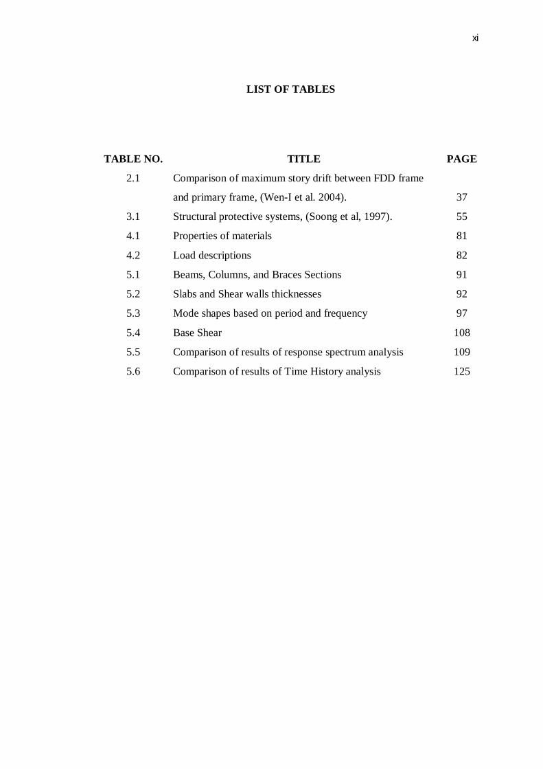
LIST OF TABLES
TABLE NO. TITLE PAGE
2.1 Comparison of maximum story drift between FDD frame
and primary frame, (Wen-I et al. 2004).
37
3.1 Structural protective systems, (Soong et al, 1997). 55
4.1 Properties of materials 81
4.2 Load descriptions 82
5.1 Beams, Columns, and Braces Sections 91
5.2 Slabs and Shear walls thicknesses 92
5.3 Mode shapes based on period and frequency 97
5.4 Base Shear 108
5.5 Comparison of results of response spectrum analysis 109
5.6 Comparison of results of Time History analysis 125

xii
LIST OF FIGURES
FIGURE NO. TITLE PAGE
1.1 Historical earthquakes around Peninsular Malaysia,
(Azlan. A, et al, 2005)
5
2.1 worldwide earthquake distribution, Preliminary
Determination of Epicenters, 1963-1998.
11
2.2 Behavior of rigid frame due to lateral loads, (Council on
tall buildings and urban habitat, 1995).
14
2.3 Shear wall structures, (Council on tall buildings and
urban habitat, 1995).
15
2.4 Wall frame structure, (Council on tall buildings and urban
habitat, 1995).
16
2.5 (a) Viscoelastic shear damper; (b) diagonal bracing
configuration with viscoelastic damper, (Nishant. K.
R. et al, 2009).
23
2.6 TADAS device, (Chopra, 2002). 24
2.7 Slotted Bolted Connection (SBC) 24
2.8 Building frames equipped with energy dissipaters, (De la
cruz. S. T., 2006)
28
2.9 Envelope of Maximum Roof Displacement, (Vaseghi. J.
et al. 2009).
30
2.10 Envelope of Maximum Base Shear, (Vaseghi. J. et al.
2009).
31
2.11 Envelope of Column axial force, (Vaseghi. J. et al. 2009). 32
2.12 Story Displacement Comparison, (Carlos Y.L. et al.
2003).
33
2.13 Photos of the test frame and attached friction damper,
(Wen-I et al. 2004).
35

xiii
2.14 Comparison of storey drift between the primary and the
damped frame for input of (a) El Centro, (b) Kobe and (c)
Chi-Chi earthquakes, (Wen-I et al. 2004).
37
2.15 Friction dampers as X-brace and chevron brace, (Moe
Cheung et al. 2000).
39
2.16 Time histories of energy input and energy dissipated,
(Pasquin. C. et al. 2002).
41
2.17 Time history of displacement of roof, (Pasquin. C. et al.
2002).
41
2.18 Hysteretic loop of a friction damper in a diagonal brace,
(Pasquin. C. et al. 2002).
41
2.19 Time history of deformation of damped bracing,
(Pasquin. C. et al. 2002).
42
2.20 Reduction of column axial force, (Pasquin.C. et al. 2002). 42
2.21 Experimental setup of scaled frame model with FDD,
(Imad H et al. 2002).
43
2.22 Effect of forcing frequency on moment–rotation loops,
(Imad H et al. 2002).
44
2.23 (a) Effect of displacement amplitude (b) Energy
dissipation–displacement relation, (Imad H et al. 2002).
45
2.24 Comparison between the third floor displacements of the
bare frame and of the frame protected with dissipaters,
(De la Cruz. S.T. et al. 2006).
46
2.25 Displacement of story due to effect of TMD, (An-Pei
Wang and Yung-Hing Lin. 2006).
47
2.26 Average acceleration elastic spectra for different damping
ratios, (Mohsen Tehranizadeh and Farzaneh Hamedi.
2002).
48
2.27 Top storey relative horizontal displacements (7-storey
building), (Semih S et al. 2003).
49
2.28 Top storey relative horizontal displacements (10-storey
building), (Semih S et al. 2003).
50

xiv
2.29 Top storey relative horizontal displacements (20-storey
building), (Semih S et al. 2003).
50
2.30 Base shear (20-storey building), (Semih S et al. 2003). 51
3.1 Dry friction hysteresis loop, (De la cruz. S. T., 2006). 61
3.2 Pall Friction Dampers, diagonal and X-bracing, (Pasquin.
C., 2002).
63
3.3 Responses versus Slip Load, (Pasquin. C., 2002). 64
3.4 Comparison of hysteresis loops of different kinds of
dampers, (Pasquin. C., 2002).
65
3.5 Schematic friction damped model, (Aliyeh Jowrkesh
Safai, 2001).
67
3.6 Force relationship of a friction damped model, (Aliyeh
Jowrkesh Safai, 2001).
68
3.7 Force-displacement hysteresis loop of a friction damped
model, (Aliyeh Jowrkesh Safai, 2001).
69
3.8 The plot of dynamic amplification equation 70
4.1 Luth Headquarters Building, Kuala Lumpur, Malaysia 78
4.2 Modeled structure in SAP2000 80
4.3 Detail of floors 82
4.4 Response spectrum Euro Code 8 Function 83
4.5 Response spectrum IBC2003 Function 84
4.6 Response spectrum Synthetic Function 84
4.7 Time History Synthetic Function (Rapid-KL) 85
4.8 Padang Earthquake Time History (30/September/2009) 85
4.9 Hysteretic loop of a 600kN friction damper in a diagonal
brace, (Pasquin. C. et al, 2004).
87
4.10 Configuration of friction dampers in damped model 87
5.1 First mode shape of Un-damped structure, = 3.17 93
5.2 Second mode shape of Un-damped structure, =
0.9319
94
5.3 Third mode shape of Un-damped structure, =
0.417
94
5.4 First mode shape of Damped structure, = 2.9808 95

xv
5.5 Second mode shape of Damped structure, =
0.9087
96
5.6 Third mode shape of Damped structure, = 0.4045 96
5.7 Displacement of stories 99
5.8 Axial Load of Columns 101
5.9 Shear Load of Beams 103
5.10 Bending Moment of Beams 105
5.11 Axial Loads of Beams 107
5.12 (a) Un-Damped structure (Max is 0.2063 cm, Min is -
0.1816 cm), (b) Damped structure (Max is 0.1624 cm,
Min is -0.1178 cm), Reduction: 27.8%
110
5.13 (a) Un-Damped structure (Max is 68.61 KN, Min is -
57.95 KN), (b) Damped structure (Max is 54.57 KN, Min
is -40.77 KN), Reduction: 24.7 %
112
5.14 (a) Un-Damped structure (Max is 0.1095 KN, Min is -
0.1589 KN), (b) Damped structure (Max is 0.09253 KN,
Min is -0.1216 KN), Reduction: 20.2 %
114
5.15 (a) Un-Damped structure (Max is 1.288 KN.m, Min is -
0.8878 KN.m), (b) Damped structure (Max is 0.9861
KN.m, Min is -0.75 KN.m), Reduction: 20.2 %
115
5.16 (a) Un-Damped structure (Max is 12.07 KN, Min is -
10.21 KN), (b) Damped structure (Max is 9.952 KN, Min
is -8.265 KN), Reduction: 18.2 %
116
5.17 (a) Un-Damped structure (Max is 206.7 KN, Min is -
190.1 KN), (b) Damped structure (Max is 185.2 KN, Min
is -167.5 KN), Reduction: 11.11 %
117
5.18 (a) Un-Damped structure (Max is 8.46 mm, Min is -8.52
mm), (b) Damped structure (Max is 4.21 mm, Min is -
3.54 mm), Reduction: 54.4%
119
5.19 (a) Un-Damped structure (Max is 244 KN, Min is -248
KN), (b) Damped structure (Max is 141.6 KN, Min is -
121.8 KN), Reduction: 46.46 %
120
xvi
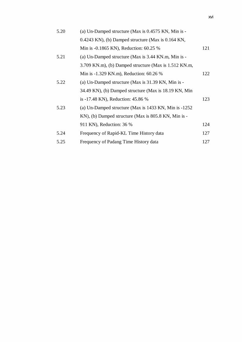
5.20 (a) Un-Damped structure (Max is 0.4575 KN, Min is -
0.4243 KN), (b) Damped structure (Max is 0.164 KN,
Min is -0.1865 KN), Reduction: 60.25 %
121
5.21 (a) Un-Damped structure (Max is 3.44 KN.m, Min is -
3.709 KN.m), (b) Damped structure (Max is 1.512 KN.m,
Min is -1.329 KN.m), Reduction: 60.26 %
122
5.22 (a) Un-Damped structure (Max is 31.39 KN, Min is -
34.49 KN), (b) Damped structure (Max is 18.19 KN, Min
is -17.48 KN), Reduction: 45.86 %
123
5.23 (a) Un-Damped structure (Max is 1433 KN, Min is -1252
KN), (b) Damped structure (Max is 805.8 KN, Min is -
911 KN), Reduction: 36 %
124
5.24 Frequency of Rapid-KL Time History data 127
5.25 Frequency of Padang Time History data 127

xvii
LIST OF ABBREVIATIONS
TITEL
IBC - International Building Code
NEHRP - National Earthquake Hazards Reduction Program
ADAS - Added Damping And Stiffness
SMRF - Special Moment Resisting Frame
FEMA - Federal Emergency Management Agency
RC - Reinforced Concrete
SBC - Slotted Bolted Connection
PED - Passive Energy Dissipation
VE - Viscoelastic
SDOF - Single Degree of Freedom
U.S. - United State of America
DBE - Design Basis Earthquake
MCE - Maximum Considered Earthquake
FDD - Friction Damper Device
EC - Euro code 8
FE - Finite Element
2D - 2 Dimensional
3D - 3 Dimensional

xviii
RSA - Response Spectrum Analysis
THA - Time History Analysis
SEER - Engineering Seismology and Earthquake Engineering
Research

xix
LIST OF SYMBOLS
TITEL
m - Meter
cm - Centimeter
mm - Millimeter
kN - Kilo Newton
- Kilo Newton per millimeter square
- Newton per millimeter square
- Kilogram per centimeter square
- Kilogram per centimeter cube
g - Gravitational ground acceleration
- Global X-direction
% - Percentage
- Ground acceleration
- Ground velocity
x - Ground displacement
t - Time/period
Hz - Hertz
k - Linear elastic stiffness

xx
m - Mass
c - Damping coefficient
- Structural acceleration
- Structural velocity
u - Displacement
± - Approximation
δ - Inter story drift
b - Brace
d - Damper
ƒ - Shear force/friction coefficient
N - Applied normal force
Δt - Time step
- Strength of reinforcement
- Strength of concrete
E - Modulus of elasticity
G - Shear modulus
ν - Poisson ratio
- Yield strength
- Ultimate strength
p - Axial force
M - Bending moment
V - Shear force
i.e. - Initialism; “In other words”

xxi
- Signum Function

xxii
LIST OF APPENDICES
APPENDIX TITLE PAGE
A Hand Calculation 137

CHAPTER 1
INTRODUCTION
1.1 General
Tall buildings are subjected to vibrations. These vibrations can be due to
wind forces, earthquake excitations, machine vibrations, or may other sources. In
some cases, especially under strong earthquake excitations, these vibrations can
cause the structural damage or even collapse of structure. For the structures that
have high inherent or natural damping, the likelihood of damage will be decreased.
However, for structures subjected to strong vibrations, the inherent damping in the
structure is not sufficient to mitigate the structural response. In many situations,
supplemental damping devices may be used to control the response of structure.
1.2 Background
Among the natural phenomenon that human kinds have worried about that,
earthquakes are the most distressing ones. The place and the time of occurrence of
earthquake are unpredictable and therefore this makes them disaster phenomenon.

2
During a major earthquake, a large amount of input energy due to earthquake
is pumped into the building. The manner in which this energy is consumed in a
structure determines the level of damage. The building codes recognize that it is
economically not feasible to reconcile this energy within the elastic capacity of
materials.
The scale of designing in conventional building codes is to design structures
to resist moderate earthquakes without significant damage and avoid collapse during
major earthquakes. The primary emphasis is on life safety. The reliance for survival
is placed on ductility to dissipate energy during inelastic deformations causing
bending, twisting and cracking. Recent earthquakes have clearly demonstrated that
conventional construction, even in technologically advanced countries, is not
unaffected to destruction.
The most feared effects of earthquake are collapse of structures especially tall
building structures due to high displacement of stories. One of the key problems
with this explanation is to reduce the structural response by increasing the dissipation
of input energy due to earthquake. In the other words, if the amount of energy
getting into the structure can be controlled and a major portion of the energy can be
dissipated mechanically independent of primary structure, the seismic response of the
structure and damage control potential can be considerably improved. These
objectives can be delivered by adopting new techniques of base isolation and energy
dissipation devices. Damper devices are the most popular instruments for increasing
the dissipation of input energy.
The main goals of any structural design are safety, serviceability and
economy. Achieving these goals for the design of structures in seismic regions is
very important and difficult. Uncertainty and unpredictability of when, where and
how an earthquake will be happen, will increase the overall difficulties. The goal of
this project is studying the seismic behavior of tall building structures by friction
damper.
3
According to the increment of population every year, tall building structures
have significant role in countries. Therefore, the design of these buildings should be
more accurate than other buildings. In the other words, the design of tall building
structures in seismic regions is more challenging, (Council on tall buildings and
urban habitat, 1995).
Finite Element Method (FFM) is a numerical method that can be used to
solve different kinds of engineering problems in the stable, transient, linear or
nonlinear cases (Bathe, 1996). Among finite element method software’s, SAP2000
is known as one of the most precise and practicable software in industry and
university researches. It is used for dynamic analysis such as earthquake and water
wave loading on structures.
1.3 Problem Statement
Large-magnitude long-distance earthquakes generated from Sumatra have
significant potential engineering implications in Singapore and the Malaysia
Peninsula due to accentuation by resonance in buildings. In addition, as the high of
building increases, the weight of structure will be increased as well as the
fundamental period of building, therefore, the displacements of stories or story drifts
as well as story shears increase. In the other words, Long-distance earthquakes
generated from Sumatra have been a cause for concern in recent years for countries
in the Indo-China region including Singapore, Malaysia and Thailand. In addition,
Long-distance earthquakes have long period, therefore, as it mentioned earlier, tall
buildings have long period too and then phenomenon of resonance may be occurred.
For example, long-period seismic waves generated by large-magnitude earthquake
events could be amplified by some four to six folds as a result of resonance.
(Balendr. T. et al. 2005). One criticism of much of the literature on above
explanation is that, although, Malaysia is located in low seismic activity area but the
4
active earthquake fault line through the centre of Sumatra just lies 350 km from
Peninsular.
Historical seismicity data of the region covering the past 100 years shows
numerous occasions when low-intensity seismic waves reached Peninsular; the
acceleration of the infrastructure is estimated to be about 3% gravitational
acceleration. Neither casualty nor significant damage has been recorded from these
events and hence no seismic provisions have been incorporated into building
regulations to date. Consequently, there is generally little attention to design and
detailing for ductile behavior of the structure in the region.
In addition, according to studies, the damping ratio of structures is generally
less than 10%, and also, by increasing the height of structures, damping ratio will be
decreased, (Amr. S. E., and Luigi. D. S., 2008). Therefore, the amount of elements
that are needed to resistant the lateral loads increase, so, the cost of construction
increase dramatically.

5
Figure 1.1 Historical earthquakes around Peninsular Malaysia, (Azlan. A, et al,
2005)
1.4 Objectives
The objectives of this study can be listed as follows:
a) Remodeling of a tall building structure (Luth Headquarters building) by
friction damper.
b) Determining the effects of large-magnitude, long-distance earthquakes
generated from Sumatra on seismic behavior of tall buildings of Malaysia
Peninsula.
c) Studying the seismic behavior of existing tall building structure by friction
damper, when seismic activity occurs using time history, response spectrum
and free vibration analysis.

6
1.5 Scope of study
a) Earthquake characteristics
b) Response of tall building structures
c) Damper characteristics (Types of damper devices)
d) Evaluation of response of tall building structures equipped by friction damper
1.6 Organization of Study
The preparing of the objectives and scopes of study are explained as below;
Stage 1: Explaining of the project on the objectives and scopes of the study
It is to verify the feasibility of the study outcomes and planning of
methodology in efficient thesis of input and output.
Stage 2: Literatures, collecting data and modeling of structures
Initial study should be done to understand the behavior of the tall building
structure and best solution for retrofitting it. Knowing the performance of the tall
building structure subjected to earthquake loading is essential to assume the structure
behave according to literature findings. Obtaining the information of model before
head and spearhead the modeling technique is part of the requirement in successful
overall analysis.

7
Stage 3: Verification of retrofitting devices and modeling
The purpose of this stage is to identify appropriate and application of
retrofitting devices, which is the friction dampers devices. In addition, the
theoretical background of the frame equipped by friction damper device is also
included to verify the concept of work on the device. Material properties and
analysis methods have been determined to obtain correct mode shapes. The structure
with and without damper has been modeled by SAP2000 software to verify the
response of structure with appropriate earthquake signals. In other words, the
models are proposed with (damped) and without (UN damped) friction damper for
comparison purposes.
Stage 4: Vulnerability assessment of modeling and response analysis
The response spectrums and Time histories analysis have been done to find
responses of the two models.
Stage 5: Discussion and conclusion
Summary of the project according to the different analysis methods and the
proposed retrofitting device will be presented. Comments on the further
improvement to the study are to be enumerated.