security systems and alarms inspection board code … · 7.5 tamper security ... alarm systems...
TRANSCRIPT
© SSAIB 2014 Page 1 of 22 SS2004: Issue 5: 04/14
|
Security Systems and Alarms Inspection Board
Code of Practice
For
Vacant / Void Property Alarm Systems
Issue 5: April 2014
Authorised: G C Tate Position: Chief Executive
Signature: Date: 14th April 2014
© Copyright 2014 Security Systems and Alarms Inspection Board (SSAIB). Unless explicitly stated otherwise, all rights including those in copyright in the content of this document are owned by or controlled by the Security Systems and Alarms Inspection Board (SSAIB). Except as otherwise expressly permitted under copyright law or under the terms and conditions of any licence granted by SSAIB, the content of this document may not be modified, copied, reproduced, republished, downloaded, posted, broadcast or transmitted in any way without first obtaining SSAIB’s written permission.

© SSAIB 2014 Page 2 of 22 SS2004: Issue 5: 04/14
Contents
Introduction .............................................................................................................. 4
0 Scope ................................................................................................................. 4
1 Reference documents ......................................................................................... 4
2 Definitions and abbreviations .............................................................................. 4
2.1 Definitions .................................................................................................. 4
2.2 Abbreviations ............................................................................................. 8
3 System Functions ............................................................................................... 8
4 System Components ........................................................................................... 8
5 Security grade of TAS ......................................................................................... 9
5.1 Basic TAS .................................................................................................. 9
5.2 Enhanced TAS ........................................................................................... 9
6 Environmental classification ................................................................................ 9
6.1 Environmental Class II – Indoor – General .................................................. 9
6.2 Environmental Class III – Outdoor – Sheltered or indoor extreme conditions ................................................................................................... 9
7 Functional requirements ...................................................................................... 9
7.1 Intruder detection ....................................................................................... 9
7.2 Control Equipment .................................................................................... 10
7.3 Operation ................................................................................................. 11
7.4 Notification ............................................................................................... 12
7.5 Tamper security ........................................................................................ 13
7.6 Interconnections ....................................................................................... 13
7.7 Event recording ........................................................................................ 14
7.8 Power supplies ......................................................................................... 14
8 Remote manned centre and ARC ...................................................................... 15
9 Electrical safety ................................................................................................ 15
10 Application guidelines ....................................................................................... 15
10.1 General .................................................................................................... 15
10.2 Other components .................................................................................... 15
10.3 Electrical safety ........................................................................................ 15
10.4 Unwanted alarms ...................................................................................... 15
10.5 Responsibility ........................................................................................... 15
10.6 Competence ............................................................................................. 15
10.7 Tools ........................................................................................................ 16
10.8 Confidentiality .......................................................................................... 16
10.9 Consultation ............................................................................................. 16
10.10 Compatibility .................................................................................. 16
10.11 System Design ............................................................................... 16
10.12 System design proposal ................................................................. 17
10.13 Selection of components ................................................................ 17
10.14 Siting of TAS components .............................................................. 17
10.15 Interconnections ............................................................................ 17
Deleted: 8
Deleted: 11
Deleted: 14
Deleted: 15
Deleted: 16
Deleted: 16
Deleted: 16
Deleted: 16
Deleted: 16
Deleted: 16
Deleted: 16
Deleted: 18
© SSAIB 2014 Page 3 of 22 SS2004: Issue 5: 04/14
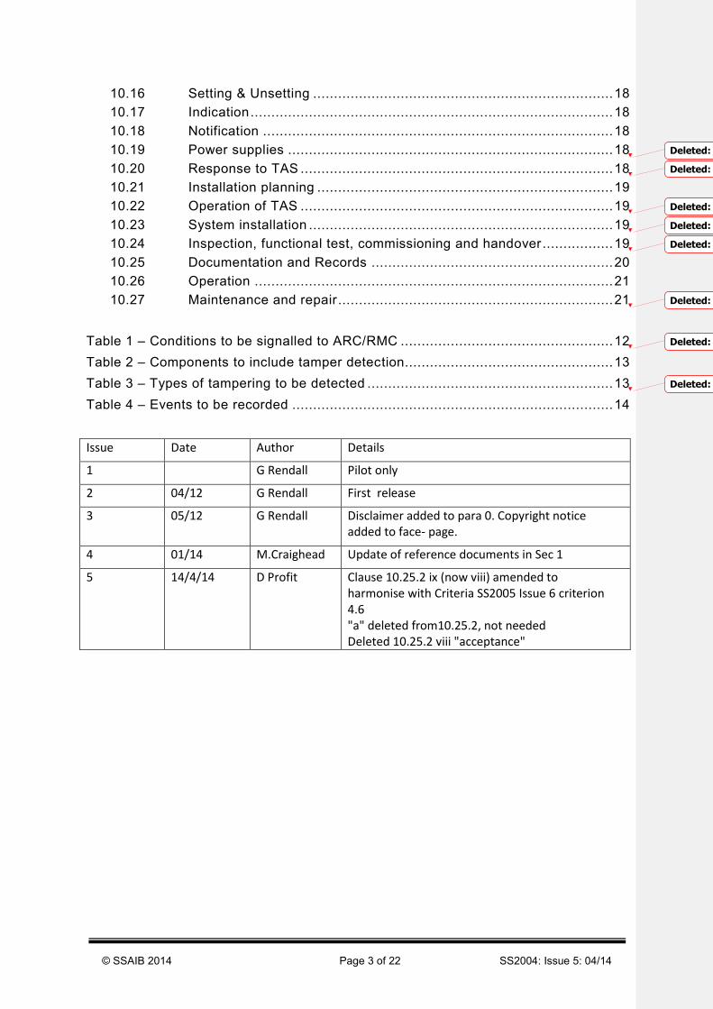
10.16 Setting & Unsetting ........................................................................ 18
10.17 Indication ....................................................................................... 18
10.18 Notification .................................................................................... 18
10.19 Power supplies .............................................................................. 18
10.20 Response to TAS ........................................................................... 18
10.21 Installation planning ....................................................................... 19
10.22 Operation of TAS ........................................................................... 19
10.23 System installation ......................................................................... 19
10.24 Inspection, functional test, commissioning and handover................. 19
10.25 Documentation and Records .......................................................... 20
10.26 Operation ...................................................................................... 21
10.27 Maintenance and repair .................................................................. 21
Table 1 – Conditions to be signalled to ARC/RMC ................................................... 12
Table 2 – Components to include tamper detection.................................................. 13
Table 3 – Types of tampering to be detected ........................................................... 13
Table 4 – Events to be recorded ............................................................................. 14
Issue Date Author Details
1 G Rendall Pilot only
2 04/12 G Rendall First release
3 05/12 G Rendall Disclaimer added to para 0. Copyright notice added to face- page.
4 01/14 M.Craighead Update of reference documents in Sec 1
5 14/4/14 D Profit Clause 10.25.2 ix (now viii) amended to harmonise with Criteria SS2005 Issue 6 criterion 4.6 "a" deleted from10.25.2, not needed Deleted 10.25.2 viii "acceptance"
Deleted: 19
Deleted: 19
Deleted: 20
Deleted: 20
Deleted: 20
Deleted: 22
Deleted: 13
Deleted: 14
© SSAIB 2014 Page 4 of 22 SS2004: Issue 5: 04/14
Introduction
This code of practice is intended to provide guidance to those responsible for specifying, designing, installing commissioning and where required, repairing temporary alarm systems and equipment.
The initial response to the detection of an unauthorised person or hazard will usually be by the service provider’s own personnel, a third party private security company or the client’s own staff
0 Scope
This code of practice includes guidance on the installation and commissioning of temporary alarm systems and/or equipment installed within void or vacant property.
This Code of Practice is intended to provide guidance to those responsible for specifying, designing, installing, commissioning and where required, repairing temporary alarm systems and equipment and is it not a substitute for detailed advice in specific circumstances. Although great care has been taken in the compilation and preparation of this Code of Practice, SSAIB cannot in any circumstances accept responsibility for errors, omissions or advice given or for any losses arising from reliance contained in this Code of Practice.
1 Reference documents
BS 5979:2007. Code of practice for remote centres receiving signals from security systems.
BS7499:2013 Static site guarding and mobile patrol services
BS 7858: 2012: Security screening of individuals employed in a security environment
EN 50130-5: 2011 Alarm systems - Part 5: Environmental test methods
EN 60950-1: 2012+A2: 2013 Information technology equipment - Safety – Part 1: General requirements
RISC Authority document S6: Electronic Security Systems: Guidance on key-holding selection and duties
Note: attention is drawn to the IPCRes (forerunner of the RISC Authority) guidance document entitled “The selection and use of electronic security systems in empty buildings”.
2 Definitions and abbreviations
2.1 Definitions
For the purposes of this document, the following terms and definitions apply:
4.1.1.
Alarm Warning of the presence of a hazard to life, property or the environment.
4.1.2.
Alarm receiving centre Continuously manned centre complying with BS5979 Category 2 to which information concerning the status of one or more TAS is reported.

© SSAIB 2014 Page 5 of 22 SS2004: Issue 5: 04/14
4.1.3.
Alarm condition Condition of a TAS, or part thereof, which results from the response of the system to the presence of a hazard.
4.1.4.
alarm signalling system equipment and network used to transfer information concerned with the state of one or more TAS to one or more alarm receiving centre or one or more remote manned centres.
4.1.5.
As-fitted document Document in which details of TAS as actually installed are recorded.
4.1.6.
Control equipment Equipment for receiving, processing, controlling, indicating and initiating, the onward transmission of information.
4.1.7.
commissioning Putting a TAS into operational mode.
4.1.8.
Confirmation of activation Means of confirming the detection of an intruder, e.g. by requiring the activation of more than one intrusion detector or audibly or visually verifying an alarm activation at an ARC or RMC.
4.1.9.
Client Individual or corporate body responsible for acquiring the TAS.
4.1.10.
Detector Device designed to generate an intruder alarm signal or message in response to the sensing of an abnormal condition indicating the presence of a hazard.
4.1.11.
Documentation Paperwork (or other media) prepared during the design, installation, commissioning and handover of TAS recording details of the TAS.
4.1.12.
Equipment schedule List of equipment to be installed or actually installed.
4.1.13.
Fault condition Condition of an alarm system which prevents a TAS or parts thereof from functioning normally.
© SSAIB 2014 Page 6 of 22 SS2004: Issue 5: 04/14
4.1.14.
Indication Information (in audible, visual or any other form) provided to assist the user in the operation of a TAS
4.1.15.
Interconnection Means by which messages and/or signals are transmitted between TAS components.
4.1.16.
Local notification Passing of an alarm, tamper or fault conditions to an audible or visual warning device(s).
4.1.17.
Notification Passing of an alarm, tamper or fault conditions to a warning device(s) and/or ARC or RMC.
4.1.18.
Operational mode State of an alarm system when it is complete, commissioned and ready for use.
4.1.19.
power supply that part of an alarm system which provides power for TAS or any part thereof.
4.1.20.
remote notification passing of alarm, tamper or fault conditions to an ARC or RMC indicating that a hazard has been detected at a supervised premises.
4.1.21.
remote manned centre A building with secure access that is continuously manned by personal trained in dealing with system activations and having a means of communicating with the responding company duty personnel, the key-holders and, if necessary, the emergency services.
4.1.22.
Responding personnel Person or organisation responsible for taking appropriate action agreed with the client following the activation of a TAS.
Note: This may be the organisation that supplied the TAS or a third party
4.1.23.
Set Status of a TAS or part thereof in which an alarm condition can be notified.
4.1.24.
Service provider Organisation responsible installing a TAS.

© SSAIB 2014 Page 7 of 22 SS2004: Issue 5: 04/14
4.1.25.
Specifier Individual or corporate body responsible for stipulating the requirements TAS will be required to meet
4.1.26.
Supervised premises Part of a building and/or site in which an intrusion or hazard may be detected by a TAS.
4.1.27.
System components Individual items of equipment which constitute a TAS when configured together.
4.1.28.
System record History of maintenance, faults, repair or modifications to the TAS.
EXAMPLE A log book or electronic record.
4.1.29.
Tamper Deliberate interference with a TAS or part thereof.
4.1.30.
tamper alarm Alarm generated by tamper detection.
4.1.31.
Tamper condition Condition of a TAS in which tampering has been detected.
4.1.32.
Tamper protection Methods or means used to protect a TAS or part thereof against deliberate interference.
4.1.33.
Temporary alarm system An alarm system generally but not exclusively battery powered designed to be rapidly installed on a non-permanent basis with the ability to detect and indicate the presence of unauthorised persons or a hazard within void property.
4.1.34.
Unset Status of a TAS or part thereof in which an alarm condition cannot be notified.
4.1.35.
User Person authorized to operate a TAS.
4.1.36.
Unwanted alarm Alarm conditions not generated by an intrusion or attempted intrusion into the supervised premises or site.

© SSAIB 2014 Page 8 of 22 SS2004: Issue 5: 04/14
4.1.37.
Vacant / Void property Unused premises, e.g. vacant or unoccupied buildings or enclosed sites
4.1.38.
Warning device A device that gives an audible alarm in response to a notification.
Note: A warning device may also provide alert indications providing such indications are easily distinguishable from an alarm.
4.1.39.
Wire-free interconnection Interconnection conveying information between TAS components without physical media, e.g. using RF techniques.
2.2 Abbreviations
For the purposes of this document, the following abbreviations apply.
ARC Alarm Receiving Centre
ASS Alarm Signalling System
CE Control Equipment
PIR Passive Infra-Red
PS Power Supply
RMC Remote Manned Centre
TAS Temporary Alarm System
SE Signalling Equipment
WD Warning Device
3 System Functions
A temporary alarm system shall include a means to operate the system, e.g. set/unset, a means of detecting an unauthorized person or hazard, a means of processing the information and a means to transmit activations to either a Remote Manned Centre or an Alarm Receiving Centre. In addition it is permissible to signal information relating to the status of the system to trained responding personnel. Additional audible warning devices may be provided.
4 System Components
A temporary alarm system may consist of a single unit comprising a means of control (setting/unsetting) detection and notification or may be made up of various individual devices which together provide the same overall TAS functions.
When individual devices are employed the recommendation included in clause 7.6 relating to interconnections should be applied.

© SSAIB 2014 Page 9 of 22 SS2004: Issue 5: 04/14
5 Security grade of TAS
Security grading
This code of practice describes two security grades, Basic and Enhanced. The security grade of TAS will depend upon the performance required as determined by the service provider in agreement with the client.
5.1 Basic TAS
A Basic TAS should include remote notification to an RMC. Local notification may also be included.
A Basic TAS is intended to be used when remote notification to a Category II BS 5979 compliant alarm receiving centre (ARC) is not considered necessary.
5.2 Enhanced TAS
An Enhanced TAS should include remote notification to a Category II BS 5979 compliant ARC. Local notification may also be included.
Note: An Enhanced TAS is intended to be used when remote notification to a Category II BS 5979 compliant alarm receiving centre is considered necessary.
6 Environmental classification
The environmental class of each TAS component should be determined by the environmental conditions in which the component is expected to operate. Components shall be suitable for use in one of the following environmental classes. Manufacturers should specify test requirements appropriate to the environmental class of each system component. EN 50130-5 describes environmental test methods to be applied to TAS components.
6.1 Environmental Class II – Indoor – General
Environmental influences normally experienced indoors when the temperature is not well maintained (e.g. in corridors, halls or staircases and where condensation can occur on windows and in unheated storage areas or warehouses where heating is intermittent).
Note: Temperatures may be expected to vary between -10 °C and +40 °C with average relative humidity of approximately 75 % non-condensing.
6.2 Environmental Class III – Outdoor – Sheltered or indoor extreme conditions
Environmental influences normally experienced out of doors when TAS components are not fully exposed to the weather or indoors where environmental conditions are extreme.
Note: Temperatures may be expected to vary between -25 °C and +50 °C with average relative humidity of approximately 75 %
7 Functional requirements
Detection of intruders, hazards, tampering and the recognition of faults
7.1 Intruder detection
An individual detector may be configured to require more than one activation to generate an alarm condition.

© SSAIB 2014 Page 10 of 22 SS2004: Issue 5: 04/14
7.1.1 Intrusion detectors
Intrusion detectors, either forming part of a stand alone TAS or linked to the CE by either hard wire or wire-free interconnections should include the following mandatory attributes:-
a) Basic and Enhanced grade systems
i. When using wire-free interconnections the detector battery should be monitored and signal transmitted via the CE to the RMC or ARC indicating battery power is low.
Note: Requirements relating to power supplies are included in clause 7.8 and 10.19.
b) Enhanced grade system
i. include a means of detecting the detector has been moved from its designated mounting position (shock sensor, inertia sensor or back tamper)
7.1.2 Other types of detectors
TAS may include other types of detectors providing these do not adversely influence the operation of intrusion detectors. An example of the types of detectors that could be included is listed below:
i. Smoke or heat detectors
ii. Flood or water movement detectors
iii. Gas detectors
7.2 Control Equipment
Control Equipment, either forming part of a stand alone TAS or a system made up of individual devices, should include the following mandatory attributes:-
7.2.1 Basic TAS – CE requirements
CE employed in Basic TAS should:
i. Be of substantial construction such that they can resist a physical attack.(see 7.5.1)
ii. Include a means to detect tamper and removal from mounting. (see 7.5.2)
iii. Include provision for anchoring to the structure of the building.(see 7.5.1)
iv. Include a secure method of setting/unsetting e.g. pin code or unique key.(see 7.3.2)
v. Include a reliable means of remote notification, e.g. an ASS (see 7.4.2)
vi. Include minimum memory capability in the both in the CE and at the RMC (see 7.7)
Requirements for tamper security are specified, in detail, in 7.5.
7.2.2 Enhanced TAS - Additional requirements for CE
In addition to the requirements applicable to Basic TAS an Enhanced TAS should also include:
i. Means to detect an attack on the CE and alarm signalling equipment.
ii. Means of providing confirmation of activation.
iii. Means of reliably providing remote notification, e.g. a reliable ASS signalling to a BS 5979 Category II complaint ARC.(see 5.2)
© SSAIB 2014 Page 11 of 22 SS2004: Issue 5: 04/14
iv. Means of downloading all events from the CE to an ARC.
v. Means of uploading information to the CE.
vi. An event log meeting the requirements of 7.7 memory capability – both in the CE and duplicated at the ARC.
Note: Requirements for tamper security are specified, in detail, in 7.5
7.2.3 Optional additional features of CE that may be included
In additional to mandatory requirements as specified 7.2.1 and 7.2.2 the optional features listed below may be included providing these do not compromise compliance with the requirements of 7.2.1 and 7.2.2:
i. Method of checking that a walk test of all movement detectors has been satisfactorily completed before the system can be set by a guard ( generally after a guard has attended an activation)
ii. Facility to monitor other conditions within the building, e.g. temperature, presence of gas, presence of water.
iii. Personal attack feature
iv. Lone worker facility
7.3 Operation
When an intrusion or tamper detector is activated or a fault occurs the TAS shall provide remote notification. Local notification may also be provided. In addition the TAS may also communicate with responding personnel.
7.3.1 Access to TAS
A CE should be provided with a minimum of two access levels for setting and unsetting the system for the following personnel:
i. Key-holders
ii. alarm engineers
Additional access levels may be provided e.g. for Guards or other third party response personnel.
7.3.2 Authorisation
Permission to gain access to the functions of a TAS shall be restricted by the use of authorisation codes or physical keys
7.3.3 Setting and Unsetting
Setting and unsetting may be completed by authorised personnel on site or remotely by either the service provider or by staff at an appropriate RMC or ARC.
7.3.4 Indications
The following indication should be provided:
a) setting has been successfully completed
b) unsetting has been successfully completed
Indications may be visible and/or audible.

© SSAIB 2014 Page 12 of 22 SS2004: Issue 5: 04/14
7.4 Notification
7.4.1 Warning devices
If a warning device, other than the one within the CE, is provided it must be of substantial construction and have tamper detection to detect the opening of the unit and removal from its mounting.
7.4.2 Signalling systems
Means of notification should be provided (dependent on Grade) to signal to an RMC or ARC, the service provider’s duty personnel, a third party responding company personnel or the clients own staff.
Means of remote notification may include but not be limited to:
a) Wire-free e.g. radio based technology means such as GSM, SMS or GPRS
Or
b) By landline, if a suitable reliable connection is available, such as:-.
i. PSTN
ii. ADSL – broadband
Or
c) a combination of both wire-free and land line
The alarm signalling system for a Basic TAS shall be monitored between the TAS and the Remote Manned Centre at sufficient frequency to enable a failure of communication links to be detected at a Remote Manned Centre and indicated at the TAS CE within a maximum time period of 24 Hours. The indication at the CE should not appear during the set period.
The alarm signalling system for an Enhanced TAS shall be monitored between the TAS and the Alarm Receiving Centre at sufficient frequency to enable a failure of communication links to be detected at an Alarm Receiving Centre and indicated at the TAS CE within a maximum time period of 12 Hours. The indication at the CE should not appear during the set period.
Dependent on the TAS Grade the following conditions specified in Table 1 below should be signalled to a RMC or ARC.
Table 1 – Conditions to be signalled to ARC/RMC
Condition Basic grade Enhanced grade
Alarm and/or tamper M M
Battery fault M M
Interconnection fault Op M
Mains fault (if applicable)* M M
* Notification of mains faults may be delayed for a maximum of 1 h.
In the event of any of the conditions included in Table 1 above not being successfully notified received at the Remote Manned Centre or Alarm Receiving Centre the condition should be clearly recorded in the event log and, at the time of unsetting, an indication should be provided at the CE.

© SSAIB 2014 Page 13 of 22 SS2004: Issue 5: 04/14
7.5 Tamper security
7.5.1 Tamper protection
The CE, SE, WD and power supplies shall be of substantial construction and be designed to resist physical attack. CE, SE and WD should be provided with a means to be securely attached to the structure of the building.
7.5.2 Tamper detection
Tamper detection should be included in TAS component as specified in Table 2.
Types of tampering that should be detected are as specified in Table 3.
Table 2 – Components to include tamper detection
Tamper Detection – Components to Include
TAS Components Basic grade Enhanced grade
Control equipment M M
Signalling equipment M M
Power supplies M M
Movement detectors (intrusion) M M
Intrusion detectors (other than movement detectors) O M
Warning devices M M
M = Mandatory Op = Optional
Table 3 – Types of tampering to be detected
Tamper Detection – Means of tampering to be detected
TAS Components Basic grade Enhanced grade
Control equipment O & R O & R
Signalling equipment O O
Power supplies O O
Movement detectors (intrusion) O O&R
Intrusion detectors (other than movement detectors) Op Op
Warning devices O & R O & R
O = Opening by normal means R = Removal from mounting Op = Optional
7.6 Interconnections
Interconnections between the TAS components shall be suitable for the purpose and designed to provide reliable means of communication. Interconnections may be hardwired or wire-free.
The interconnections shall be monitored such that a failure of an interconnection is detected within the following time periods:
a) Basic grade TAS – 24 hours
b) Enhanced grade TAS - 5 hours
Failure of an interconnection shall be treated as a tamper condition.

© SSAIB 2014 Page 14 of 22 SS2004: Issue 5: 04/14
For Enhanced TAS using wire-free interconnections there should be a method of monitoring that intrusion movement detectors are connected to the system during the setting procedure.
7.6.1 Timing
All alarm, tamper or fault conditions with an active period (e.g. in alarm condition) exceeding 400ms shall result in the generation of an alarm, tamper or fault condition within 10 seconds
All fault conditions with an active period (e.g. in alarm condition) exceeding 10 seconds shall result in the generation of an alarm, tamper or fault condition within 10 seconds
7.7 Event recording
Dependent upon the Grade of a TAS the events listed below shall be recorded in the CE and RMC or ARC.
Table 4 – Events to be recorded
Event Basic grade Enhanced grade
Set/Unset M M
Alarm and/or tamper M M
Mains fault ( if applicable) M M
Battery fault M M
Interconnection fault Op M
ASS Signalling fault Op M
Unsuccessful signal of events to an RMC or ARC Op M
The means used to record the mandatory events shall be protected against the accidental or deliberate deletion or alteration of the contents.
The means of recording events shall have a capacity to record the following events:
Basic grade TAS - 200 events
Enhanced grade TAS - 500 events
When the capacity of the means of recording is finite and the event recorder reaches maximum capacity, further events may cause the oldest events to be erased.
When event recording is provided at an ARC or RMC a local indication shall be provided if the transmission of events to the remote location has been unsuccessful.
The number of events recorded from any single source shall be limited to at least three and a maximum of 10 during any set or unset period.
7.8 Power supplies
When the TAS prime power source has a finite capacity e.g. is a battery the battery must have sufficient capacity to power the system in all normal conditions of use, including expected communications with the RMC or ARC for the periods specified below.
i. Basic grade system - 3 months
ii. Enhanced grade system - 6 months
A low battery indication must be signalled to an RMC or ARC if the battery capacity falls below that required to power the system for 7 days.
Where the PS is a battery, allowance should be made for loss of capacity during the lifetime of the battery.

© SSAIB 2014 Page 15 of 22 SS2004: Issue 5: 04/14
When the TAS power supply includes a provision to use mains power the power supply must automatically switch over to battery power if the mains fail, the changeover must not adversely influence the functioning of the TAS. The battery must have sufficient capacity to power the system in all normal conditions of use, including expected communications with the RMC or ARC for the period of 3 months.
8 Remote manned centre and ARC
A remote manned centre (RMC) shall meet the following requirements:-.
i. Be located in a secure building
ii. Be continuously manned by trained personnel.
iii. Have a suitable means of communicating with responding company duty personnel, the key-holders and if necessary the emergency services
An Alarm Receiving Centre (ARC) should be independently certified as conforming to BS 5979 (Category 2) by an accredited certification body.
9 Electrical safety
The TAS components shall provide protection against electrical shock and the consequential hazards in accordance with the requirements of EN 60950-1.
10 Application guidelines
10.1 General
The system should be installed and configured in accordance with the system design proposal. Any deviations, from the design proposal, should be agreed, in writing, with the client.
10.2 Other components
Components of other systems may be combined or integrated with TAS providing the performance of TAS components is not adversely influenced.
10.3 Electrical safety
National or European requirements relating to safety may exist. Such requirements are not included in this code of practice and reference should be made directly to the relevant National or European standards.
10.4 Unwanted alarms
It is recommended that care should be taken by system designers, installation companies, service providers and users, to minimize unwanted alarms.
10.5 Responsibility
Responsibility for each individual stage in the process of supplying a TAS; design, installation, commissioning and hand-over should be clearly defined and agreed between the relevant parties.
10.6 Competence
Persons responsible for risk assessment and the design, installation planning, system installation, maintenance and repair of TAS should have the necessary training and experience.
© SSAIB 2014 Page 16 of 22 SS2004: Issue 5: 04/14
10.7 Tools
Persons responsible for installation planning, system installation, commissioning, maintenance, repair and inspection of TAS should have the appropriate tools and test equipment.
10.8 Confidentiality
Information relating to the design, installation, operation and maintenance of TAS should be treated as confidential.
10.9 Consultation
The design of a system should be determined in consultation with the client or specifier of the TAS (or their representative) and any other interested parties, e.g. insurers
When considered necessary, expert advice should be obtained.
10.10 Compatibility
Care should be taken during the selection of components to ensure all system components are compatible. Where any uncertainty arises the appropriate consultation should take place, e.g. with the manufacturer, supplier or another third party.
10.11 System Design
The objectives of the system design stage are to determine the extent of TAS and select components of the appropriate functionality/performance criteria, grade and environmental classification and to prepare a system design proposal, e.g. number and type of detectors and their location.
10.11.1 Location survey
10.11.1.1 Location survey -Risk
Among other factors, the contents, fixtures and fittings, construction, location and theft history of the supervised premises or site should be considered when designing a TAS.
10.11.1.2 Location survey – Other influences
The existing and potential environmental conditions at the premises should be taken into consideration when planning the TAS. It is not possible to identify all of the factors to be considered but the following represent examples known to cause problems with temporary alarm systems:-
i. extreme temperatures
ii. wildlife, domestic animals and rodents
iii. damaged windows and doors
iv. damaged or missing floorboards
v. water ingress
vi. inadequate network coverage for the alarm signalling system
vii. poor wire-free reception within the building
As far as is practical, the supervised premises should be secured in a manner that is intended to prevent unauthorised person from gaining ready access, i.e. without forcing an entry.
© SSAIB 2014 Page 17 of 22 SS2004: Issue 5: 04/14
10.12 System design proposal
A system design proposal should be prepared for submission to the client or an agent appointed by the client.
If there is a requirement for the immediate installation of a TAS then, in agreement with the client, a system design proposal may not be prepared until after the system has been installed
The system design proposal may be subject to alteration at other stages in the implementation of the system. Any such changes should be agreed between the relevant parties and the documentation amended accordingly.
10.13 Selection of components
Only components meeting the appropriate security grade and environmental class should be selected. Due regard should be taken of the need to minimize the generation of unwanted alarms.
10.14 Siting of TAS components
10.14.1 Siting CE and ASS equipment
CE and ASS equipment should be sited within the supervised area. Care should be taken to site the CE so as to prevent observation of the operation of the CE by unauthorized persons.
10.14.2 Siting of detectors
Detectors should be sited in compliance with the manufacturer’s recommendations and to provide the range and coverage determined during the design of the TAS.
10.14.3 Siting of warning devices
If separate or additional warning devices are specified the WD should be located in positions which are not readily accessible (so as to minimize risk of intentional or unintentional damage) consistent with reasonable access for servicing and so as to give effective notification of alarms.
WD should be so mounted as to minimise the possibility of removal without generating an alarm condition.
10.15 Interconnections
Interconnections appropriate to the system performance required and the environmental conditions should be selected.
Interconnections to externally mounted WD, which are accessible from outside the supervised area, should be provided with suitable tamper protection.
Where wired interconnections are used consideration should be given to the relevant electrical installation specifications and to equipment manufacturers recommendations.
When specific wired interconnections are selected these should be run inside the supervised premises. When it is impractical for interconnections to be routed inside the supervised area they should be provided with suitable tamper protection.
Cables should be run in positions where there is the least risk of physical damage. If risk of physical damage exists the cable should be mechanically protected.
All joints in interconnection wiring should be mechanically and electrically secure.
When wireless interconnections are selected careful consideration should be given to the influence of intentional or unintentional transmissions using the same frequency and/or means of signal modulation as those of the TAS.

© SSAIB 2014 Page 18 of 22 SS2004: Issue 5: 04/14
10.16 Setting & Unsetting
Care should be taken when selecting the means of setting and unsetting to prevent the generation of unwanted alarm signals whilst maintaining the ability for early detection of intruders. Whenever possible completion of setting and unsetting should require a deliberate action by the user. However timed setting is not prohibited.
10.17 Indication
An indication should be provided to show the system is set.
10.18 Notification
10.18.1 Remote notification
Many Alarm Signalling System communication formats exist for the transmission of messages between the CE and the RMC or an ARC. Care should be taken to ensure that the RMC or ARC can accept signals from the CE to be installed and process all signals correctly.
10.18.2 Warning Devices
Interconnections to externally mounted WD, which are accessible from outside the supervised area, should be provided with suitable tamper protection
Interconnections appropriate to the system performance required and the environmental conditions should be selected.
Where wired interconnections are used consideration should be given to the relevant electrical installation specifications and to equipment manufacturers recommendations.
10.19 Power supplies
The prime power source for a TAS would normally be by a battery or other self-contained uninterruptible power supply.
If the power supply is not contained within the CE the power supply must be housed in a substantial lockable container which has tamper detection and is secured to the structure of the property.
Care should be taken to ensure power supplies used in TAS are adequate for the load under both normal and alarm conditions.
Note: Functional requirements for power supplies are specified in 7.8 above.
10.20 Response to TAS
The initial response to detection of an unauthorised person or hazard will usually be by the service providers own trained personnel, a third party private security company or the clients own trained staff
The planned response following the activation of TAS should be clearly agreed and documented between the parties. The response is usually provided by one or more of the following:-
a) TAS service provider
i. Response personnel should be expected to respond to an activation of a TAS within 90 mins. but the response time will depend on availability of staff and the location of the site
ii. When on site the response personnel would be expected to check the building and/ or site for signs of intrusion or a hazard within the limitations of health and safety requirements. If the activation has been an unwanted alarm

© SSAIB 2014 Page 19 of 22 SS2004: Issue 5: 04/14
activation the responding personnel would be expected to reset the system in its entirety
b) Guards provided by third party guarding company
A third party guarding company responding to a TAS must be certificated by a UKAS accredited inspection body such as the SSAIB or NSI to the relevant standards e.g. current BS7499, Static site guarding and mobile patrol service and BS 7858, Security screening of individuals employed in a security environment. Employees should hold an appropriate SIA license.
c) Client’s own trained staff
If the client’s own staff is to respond to activations from a TAS then the client’s attention should be drawn the appropriate guidance provided in the relevant sections of the RISC Authority document S6 – Electronic Security Systems: Guidance on key holder selection and duties.
10.21 Installation planning
10.21.1 General
Due to the speed of deployment required by a specifier of a TAS the installer should ensure that adequate equipment is available at the time of installation to meet the requirements detailed in the system design proposal.
10.21.2 Manufacturers recommendations
All system components should be installed in accordance with the manufacturer’s recommendations. If installation of a component in accordance with the manufacturer’s recommendations is not possible advice should be sought from the manufacturer or supplier.
10.22 Operation of TAS
The operation of the system, particularly setting and unsetting procedures should be as simple as possible.
10.23 System installation
The system should be installed and configured in accordance with the system design proposal. Any deviations, from the design proposal, should be agreed, in writing, with the client.
Note: Due to the speed of deployment often required by specifiers of a temporary alarm system the agreement to deviations to a system design proposal may be completed after the installation has been completed.
10.24 Inspection, functional test, commissioning and handover
10.24.1 Inspection
An inspection of the system should be carried out on completion of the installation of TAS to confirm TAS has been installed in accordance with the system design proposal. Any deviations, from the system design proposal, should be recorded for inclusion in the as-fitted document.
10.24.2 Functional testing
The performance of each detector should be tested. Particular care should be taken with movement and vibration detectors which may require adjustment of range or coverage. Other types of detectors may also require final adjustment prior to commissioning.

© SSAIB 2014 Page 20 of 22 SS2004: Issue 5: 04/14
Finally a complete operational test should be carried out, including activation of any WD and ASS. Where an ASS is installed a check should be made with the remote manned centre or ARC to ensure these signals were successfully received.
10.24.3 Commissioning
On completion of the tests TAS should be placed into operational mode.
10.24.4 Handover
If possible the Handover of TAS to the user should be carried out by a person with the appropriate training and experience.
If practical a full demonstration of TAS should be provided including the operation of detectors and how these should be tested.
An explanation of the functions of the installation should also be provided. Communication procedures with the RMC or ARC should be explained.
Clear and concise operating instructions should be provided, these should include both how the CE is operated and the specific setting and unsetting procedures for the TAS. These instructions should be provided to all users responsible for operating the TAS.
10.25 Documentation and Records
10.25.1 As fitted document
The as-fitted document should be an accurate record of the installed TAS including all information relating to the equipment installed and its location. The as-fitted document should be made available to maintenance and service personnel.
10.25.2 Documentation
The following documentation should be provided to the client. The client or user should be requested to make this documentation available should TAS require modification, repair or maintenance and should also ensure the documentation is kept up to date. Documents may be provided in electronic or physical format.
i. as-fitted document;
ii. system operating instructions;
a. Operating instructions should be provided in sufficient detail to minimise the possibility of miss operation.
b. detailed instruction covering all the other functions of the TAS
iii. installation company:
the name, address and telephone number of the individual or installation company;
iv. maintenance and repair:
the name, address and telephone number of the company or individual responsible for maintaining and/or repairing the TAS, including details of how these organisations or individuals may be contacted at all times;
v. monitoring:(optional)
the name and telephone number of the ARC or RMC responsible for initiating a response to the TAS;
vi. verification:
details of any procedures relating to the verification of alarm conditions;
vii. intervention:
© SSAIB 2014 Page 21 of 22 SS2004: Issue 5: 04/14
the name, address and telephone number of the organisation responsible for attending the supervised premises following the generation of an alarm condition;
viii. SSAIB certificate of conformance.
When required by a client of a registered firm, for each individual installation, the client shall be provided with an official SSAIB certificate of conformance, stating that the system has been installed in accordance with this Code of Practice by the named SSAIB-registered firm, and such other detail as may be required.
10.25.3 Records
A system record should be provided to record any information necessary to ensure TAS operates as intended. The record should include details of the time and date of any alarm conditions, which detector was responsible for generating the alarm condition and in the case of an unwanted alarm condition, details of any remedial action initiated to prevent the occurrence of further unwanted alarm conditions. The record should also include details of any modifications or additions to the TAS.
The system record may be recorded in any medium and at a location remote from the supervised premises or site providing it is easily accessible to persons maintaining the TAS. The records should be supplied in a manner suitable for the long term preservation of the records.
10.26 Operation
The client and/or user of TAS and those responsible for the maintenance and service of TAS should be made aware of their responsibility to
i. ensure that only individuals trained to operate the system are allowed to operate it and that TAS is operated in accordance with operational instructions and training,
ii. ensure the premises or site are used and maintained in a manner such as not to cause unwanted alarms,
iii. report any defects in TAS promptly to the responsible TAS company,
iv. report any changes to the construction or to the use of the premises which might adversely influence the performance of the TAS,
v. Maintain the relevant documents and records.
10.27 Maintenance and repair
10.27.1 General
It is the client’s responsibility to arrange for TAS to be properly maintained (inspected and serviced) and repaired as necessary. An arrangement should be made between the client and a competent organisation for the maintenance, repair and replacement the batteries of the TAS. The arrangement should specify the method of liaison necessary to provide access to the supervised premises.
10.27.2 Inspection and services
To ensure the continued correct functioning of the TAS it should be periodically maintained (inspected and serviced). A maintenance schedule should be agreed immediately upon the completion of the installation.
Any batteries should be replaced at intervals not exceeding the battery and equipment manufacturer’s recommendations. Care should be taken that all equipment is properly reinstated after testing.
© SSAIB 2014 Page 22 of 22 SS2004: Issue 5: 04/14
10.27.3 Repair
In the event of any indication of a malfunction or damage to any part of TAS the user should immediately inform the organisation or individual responsible for the maintenance and repair of TAS so that any necessary remedial action may be taken. The time within which repair of TAS will commence, following a request to the organisation or individual responsible for carrying out the repairs, should be agreed.