security expert
TRANSCRIPT

Security Expert
System Controller
Installation Manual SP-C
January 2017

The Schneider Electric brand and any registered trademarks of Schneider Electric Industries
SAS referred to in this guide are the sole property of Schneider Electric SA and its
subsidiaries. They may not be used for any purpose without the owner's permission, given in
writing. This guide and its content are protected, within the meaning of the French intellectual
property code (Code de la propriété intellectuelle français, referred to hereafter as "the
Code"), under the laws of copyright covering texts, drawings and models, as well as by
trademark law. You agree not to reproduce, other than for your own personal, noncommercial
use as defined in the Code, all or part of this guide on any medium whatsoever without
Schneider Electric's permission, given in writing. You also agree not to establish any hypertext
links to this guide or its content. Schneider Electric does not grant any right or license for the
personal and noncommercial use of the guide or its content, except for a non-exclusive
license to consult it on an "as is" basis, at your own risk. All other rights are reserved.
Electrical equipment should be installed, operated, serviced and maintained only by qualified
personnel. No responsibility is assumed by Schneider Electric for any consequences arising
out of the use of this material.
As standards, specifications and designs change from time to time, please ask for
confirmation of the information given in this publication.
Trademarks and registered trademarks are the property of their respective owners.
Legal Information
SP-C | January 2017 3
Table of Contents Introduction .................................................................................................... 5
Document Conventions ...................................................................................................... 5
Grounding Requirements ............................................................................... 6
Safety Grounding ................................................................................................................ 6
Earth Ground Connection ................................................................................................... 6
Mounting ........................................................................................................ 8
Removal .............................................................................................................................. 8
Connections ................................................................................................... 9
Power Requirements .......................................................................................................... 9
Encrypted Module Network ............................................................................................... 10
Module Wiring ............................................................................................................. 11 End of Line (EOL) Resistors ....................................................................................... 11
Telephone Dialer .............................................................................................................. 12
Ethernet 10/100 Network Interface ................................................................................... 12
Configuration ................................................................................................ 13
Setting the IP Address ...................................................................................................... 13
Setting the IP Address from a Keypad ............................................................................. 14
Configuring a Controller via the Security Expert Software ............................................... 14
Adding a Controller with Default Records .................................................................. 15 Adding a Controller Based on an Existing Controller ................................................. 16 Configuring a Controller .............................................................................................. 17
Addressing Modules ......................................................................................................... 25
Door Access Control .................................................................................... 27
Wiegand Card Reader Connection ................................................................................... 27
Multiplex Wiegand Card Reader Connection ................................................................... 28
RS-485 Reader Locations ................................................................................................ 28
RS-485 Card Reader Connection (Entry Only) ................................................................ 29
RS-485 Card Reader Connection (Entry/Exit) .................................................................. 29
Door Contact Connection ................................................................................................. 30
Lock Output Connection ................................................................................................... 31
Programming the Onboard Reader .................................................................................. 32
Inputs ........................................................................................................... 34
Resistor Value Options ..................................................................................................... 35
Trouble Inputs ................................................................................................................... 35
Outputs......................................................................................................... 37
Bell/Siren Output ............................................................................................................... 37
Relay Outputs ................................................................................................................... 38
Reader Outputs ................................................................................................................ 38
Hardware Configuration ............................................................................... 39
Defaulting a Controller ...................................................................................................... 39

4 SP-C | January 2017
Temporarily Defaulting the IP Address ............................................................................. 39
LED Indicators .............................................................................................. 40
Power Indicator ................................................................................................................. 40
Status Indicator ................................................................................................................. 40
Fault Indicator ................................................................................................................... 40
Ethernet Link Indicator ...................................................................................................... 41
Modem Indicator ............................................................................................................... 41
Reader Data Indicators ..................................................................................................... 41
Bell Indicator ..................................................................................................................... 41
Relay Indicators ................................................................................................................ 42
Zone (Input) Indicators ...................................................................................................... 42
Mechanical Diagram .................................................................................... 43
Mechanical Layout ....................................................................................... 44
Technical Specifications ............................................................................... 45
Current and Validation Example ....................................................................................... 46
New Zealand and Australia .......................................................................... 47
European CE and EN 50131 ........................................................................ 48
UL and ULC Installation Requirements ........................................................ 50
UL/ULC Installation Cabinet Options ................................................................................ 50
Central Station Signal Receiver Compatibility List ........................................................... 50
ULC Compliance Requirements ....................................................................................... 50
CAN/ULC-S304-06 ..................................................................................................... 50 CAN/ULC-S319-05 ..................................................................................................... 54 CAN/ULC-S559-04 ..................................................................................................... 54
UL Compliance Requirements .......................................................................................... 58
UL1610 ....................................................................................................................... 58 UL294 ......................................................................................................................... 59
FCC Compliance Statements ....................................................................... 61
Industry Canada Statement .......................................................................... 63

Introduction Security Expert System Controller
SP-C | January 2017 5
The Security Purpose Controller is the central processing unit of the Security Expert System.
It communicates with all system modules, stores all configuration and transaction information,
processes all system communication, and reports alarms and system activity to a monitoring
station or remote computer.
Flexible module network architecture allows large numbers of modules to be connected to the
RS-485 Module Network. Up to 250 modules can be connected to the Security Expert System
in any combination to the network up to a distance of 900M (3000ft). Communication beyond
this distance requires the use of a RS-485 Network Extender
The current features of the Security Expert Controller include:
Internal industry standard 10/100 Ethernet
32 Bit advanced RISC processor with 2Gb total memory
8 high security monitored inputs
NIST Certified AES 128, 192 and 256 Bit Encryption
Document Conventions This document uses the following conventions:
Important warnings or cautionary messages to prevent equipment damage, data
loss, or other similar conditions
i
Notes with additional information such as an explanation, a comment, or a
clarification about the subject
Tips containing practical information that may help you solve a problem or
describing actions that may save you time
[TEXT] Bold text enclosed in brackets is used to show a section number or address of a
programmable option or information on programming shortcut sequences
Introduction

Security Expert System Controller Grounding Requirements
6 SP-C | January 2017
An effectively grounded product is one that is intentionally connected to earth ground through
a ground connection or connections of sufficiently low impedance and having sufficient
current-carrying capacity to prevent the build up of voltages which may result in undue hazard
to connected equipment or to persons.
Grounding of the Security Expert System is done for three basic reasons:
1. Safety,
2. Component protection, and
3. Noise reduction
Safety Grounding The object of safety grounding is to ensure that all metalwork is at the same ground (or Earth)
potential. Impedance between the Security Expert System and the building scheme ground
must conform to the requirements of national and local industrial safety regulations or
electrical codes. These will vary based on country, type of distribution system, and other
factors. The integrity of all ground connections should be checked periodically.
General safety dictates that all metal parts are connected to earth with separate copper wire
or wires of the appropriate gauge.
Earth Ground Connection The DIN Rail Enclosure and the DIN Rail Modules must be grounded to a single point earth
ground. For best results, a cold water pipe should be used with a pipe wiring clamp. If a cold
water pipe is not available, connect to a suitable ground connection in the installation. A
minimum 14AWG solid copper wire (or thicker in accordance to local authorities) shall be used
from the Security Expert System's earth connection points to the clamp on the cold water
pipe. If other earth clamps are present at the same connection point, connect the clamp below
the existing units.
The DIN Rail Enclosure includes an earth ground single point link connection via the metallic
enclosure. This single point link is the Security Expert System's earth ground. All modules that
have earth ground connections and that are installed in the same enclosure shall be
connected to this single point. A single point earth ground connection avoids the creation of
ground loops in the system and provides a single reference point to earth ground.
Grounding Requirements

Grounding Requirements Security Expert System Controller
SP-C | January 2017 7
Controller
Earth Ground Link connection
Dialer’s EarthGround Connection
PRT-RDM2-DIN
PRT-PSU-DIN
V-
SP-PSU
SP-RDM2
PRT-PSU-DINSP-I16
SP-O8
V-
AC Mains Wiring
DIN Rail Enclosure
Module Network (RS-485 N+, N-, NA and NB)
Additional DIN Rail Enclosure(s)
DIN Rail Ground Connections (one or more cabinets installaed in the same room)
DIN Rail Ground Connections (multiple cabinets in different rooms , sectors , or buildings)
DIN Rail Enclosure
Controller
Earth Ground Link connection
Dialer’s EarthGround Connection
Module Network (RS-485 N+, N-, NA and NB)
PRT-RDM2-DIN
PRT-PSU-DIN
V-
SP-PSU
SP-RDM2
PRT-PSU-DINSP-I16
SP-O8
PRT-RDM2-DINSP-I16
PRT-PSU-DINSP-I16
SP-I16
V-
DIN Rail Enclosure DIN Rail Enclosure
Sector or Building #1 Sector or Building #2 Sector or Building #3
Note that the DIN Rail Enclosure earth terminal is connected to the PSU V- terminal.
There must only be one single earth grounding point per system.

Security Expert System Controller Mounting
8 SP-C | January 2017
The Controller is designed to mount on standard DIN Rail either in dedicated DIN cabinets or
generic DIN Rail mounting strip. A section of this DIN Rail strip has been provided as a
mounting option.
When installing the Controller ensure that there is adequate clearance around all sides of the
device and that air flow to the vents of the unit is not restricted. It is recommended to install
the Controller in a location that will facilitate easy access for wiring. It is also recommended
that the Controller is installed in electrical rooms, communication equipment rooms, closets or
in an accessible area of the ceiling.
1. Hook the lower tabs under the bottom edge of the DIN Rail.
2. Push the Controller against the DIN Rail mount until the upper tab clips over the upper rail.
Removal The Controller can be removed from the DIN Rail mount using the following steps:
1. Insert a flat blade screwdriver into the hole in the tab at the top of the Controller.
2. Lever the tab up and rotate the unit off the DIN Rail mount.
Mounting

Connections Security Expert System Controller
SP-C | January 2017 9
Power Requirements Power is supplied to the Controller by a 12V DC power supply connected to the N+ and N-
terminals. The Controller does not contain internal regulation or isolation and we recommend
using an SP-PSU for this purpose, although any clean 12V DC supply is suitable. In a small
installation this same power supply can be used to supply the module network as well, so long
as the maximum load of the power supply is not exceeded.
Warning: Termination of wiring to the Controller while power is applied or the
battery is connected may cause serious damage to the unit and will VOID ALL
WARRANTIES OR GUARANTEES. Power the unit only after all wiring,
configuration and jumper settings are completed.
If using an SP-PSU module, a battery backup must be connected to the module network to
provide a monitored supply. The battery plays an important role in power conditioning and
provides a continuous source of power in the event of a power outage.
B+B- L NNAN+ N- NB
Controller SP-PSU-4A
Gel Cell Backup Batteries
NAN+ N- NBV1+ V-V1+ V1+ V1+ V1+ V1+ V- V- V- V- V-
To other moduleson network
Mains Input
+
-
+
-
Example Power Supply Connection (SP-PSU-4A)
In larger installations, the power supply may need to be split to allow for load sharing between
several supplies.
In order to comply with EN 50131-1 only one battery can be connected and
monitored per system. If more capacity is required a single, larger battery must be
used.
Connections

Security Expert System Controller Connections
10 SP-C | January 2017
Module #3 Module #1 Controller
NAN+ N- NBNAN+ N- NB NAN+ N- NB
Module #2
NAN+ N- NB
Power Supply #3 Power Supply #2 Power Supply #1
Example multiple PSU Connection
Warning: When using multiple power supplies it is important to ensure that all
ground connections (V-) are connected between all power supplies and that no
power connections (V+) are connected between any power supplies.
The auxiliary outputs (V- V+) of the Controller can be used to supply other equipment. Note
that there is no onboard regulation or isolation for these outputs - they are a fused
feed-through from the N+ N- input terminals. When using these outputs to supply other
devices, be sure not to exceed the rating of the internal fuses as outlined in the Technical
Specifications (see page 45).
Encrypted Module Network The Controller incorporates encrypted RS-485 communications technology. Connection of the
communications should be performed according to the following diagram.
SP-PSU orequivalent 12V DC
Shield is frame grounded atone point
Shields are connected togetherand Isolated
Shielded Cable
Controller Network Module Network Module
Shielded Cable
Shield notconnected
NAN+ N- NBNAN+ N- NB NAN+ N- NB
supply
Standard Network Communication Connection
Always connect the Controller's NA and NB terminals to the NA and NB terminals of the
expansion devices and keypads. The N+ and N- must connect to a 12V power supply source
capable of supplying the peak current drawn by all modules. If a shielded cable is used, the
shield must be connected at only one end of the cable. DO NOT connect a shield at both
ends.
Connections Security Expert System Controller
SP-C | January 2017 11
Warning:
The 12V N+ and N- communication input must be supplied from only one point. Connections from more than one 12V supply may cause failure or damage to the units supplying power.
Make sure that the power supply can supply enough current for the peak load drawn by all modules connected to the 12V supply, including the Controller itself.
Module Wiring
The recommended module network wiring specifications are:
Belden 9842 or equivalent
24AWG twisted pair with characteristic impedance of 120ohm
Maximum total length of cable is max 900m (3000ft)
CAT5e / CAT6 are also supported for data transmission when using ground in the same cable (to a maximum length 100m (328ft))
Warning: Unused wires in the cable must not be used to carry power to other
devices.
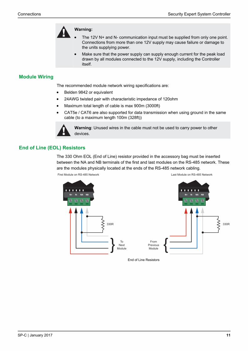
End of Line (EOL) Resistors
The 330 Ohm EOL (End of Line) resistor provided in the accessory bag must be inserted
between the NA and NB terminals of the first and last modules on the RS-485 network. These
are the modules physically located at the ends of the RS-485 network cabling.
330R 330R
NAN+ N- NB NAN+ N- NB
First Module on RS-485 Network Last Module on RS-485 Network
ToNext
Module
FromPreviousModule
End of Line Resistors

Security Expert System Controller Connections
12 SP-C | January 2017
Telephone Dialer The Controller provides the ability to communicate alarms and upload information to remote
systems using the onboard 2400bps modem. The telephone line can be connected directly to
the Controller using the onboard telephone connection terminals.
Telco line out
Telco linetip and ring input R1i
T1oR1o
T1i
Telephone Line Connection
Ethernet 10/100 Network Interface The communication between the Security Expert System and the Controller uses a 10/100
Ethernet network operating the TCP/IP protocol suite. The IP address of the Controller can be
configured using the Keypad terminal or via the built in web interface. The default IP address
is set to a static IP address of 192.168.1.2 with a subnet mask of 255.255.255.0. These IP
address settings are commonly used for internal networks.
i
Installing the Controller on an active network requires knowledge of the
configuration and structure for the network. Always consult the network or system
administrator and ask them to provide you with a fixed IP address that can be
assigned to the Controller.
When installing an Ethernet connection the Controller should be interfaced using a standard
segment (<100m in length) and should be connected to a suitable Ethernet hub or switch.
MODEM
READER
R2 RELAY 2
PRT-CTRL-DIN
MODEM
READER
R2 RELAY 2
PRT-CTRL-DIN Security Expert
Ethernet 10/100 Switch hub Connection
Temporary direct connections can be used for onsite programming by connecting directly to
the computer Ethernet port.
ClientMODEM
READER
R2 RELAY 2
PRT-CTRL-DIN
Security Expert
Ethernet 10/100 Direct Connection

Configuration Security Expert System Controller
SP-C | January 2017 13
Setting the IP Address There are two methods by which the IP address of the Controller can be set. The
recommended method is using the built in web interface:
1. With the Controller connected to your network, type the current IP address into the address bar of your web browser. (The default IP address is 192.168.1.2).
If the current IP address is not known, it can be temporarily defaulted (see page 39) to 192.168.111.222 allowing you to view and/or change the IP address using these steps.
2. Enter the user name and password.
The default user name is admin and the default password is admin.
3. Enter the required settings, save, then restart your Controller.
Configuration

Security Expert System Controller Configuration
14 SP-C | January 2017
Setting the IP Address from a Keypad If the current IP address of the Controller is not known, it can be viewed and/or changed using
a Security Expert keypad.
1. Connect the keypad to the module network.
2. Log in to the keypad using any valid Installer code. The default Installer code is 000000. If the default code has been overridden and you do not know the new codes, you will need to force the Controller into its default state (see page 39). Note that this will erase all existing programming as well as setting up the default Installer code.
3. Once logged in select Menu 4 (Install Menu) then Menu 2 (IP Menu) and view or edit the IP address, network mask, and gateway as required.
Once the settings have been changed, you must save the settings by pressing the [Arm] key.
You will be prompted to confirm the changes by pressing [Enter]. You must then restart the
Controller - either through the Menu [4],[2],[2] or by cycling the power - for the settings to take
effect.
Configuring a Controller via the Security Expert Software To connect a Controller to the software, you must add it to the system programming.
To add a Controller:
1. Login to Security Expert and select Sites > Controllers from the main menu.
2. Click Add to display the Add Controller window.
3. Select the option that best suits your needs:
Add controller with default records (see page 15): To add a single Controller
record and automatically add the specified expander modules, doors and groups as
required by your site.
Add an individual controller record: To add just the Controller. Any expander
modules, doors, groups and other programming must be added manually.
Add new controller based on an existing controller (see page 16): To duplicate
the programming of a previously configured Controller.
4. Once added, the Controller will require configuration (see page 17) to define settings including the serial number and communication parameters.
i
You may need to restart the services to bring the Controller online. Select the
services option from the Control Panel and restart the Security Expert services.

Configuration Security Expert System Controller
SP-C | January 2017 15
Adding a Controller with Default Records
If adding a Controller with default records, the Add Controller configuration window is
displayed, enabling you to automatically add the expander modules, inputs, outputs and doors
that your site will be using. All of these records can be edited later on, deleted, and/or
additional new records added.
General
Name: Defines the name of the Controller to be used as a reference when programming the system.
Count: Defines the number of Controllers to be added. If more than one Controller is added, the subsequent Controllers are assigned default names that can be edited later.
Controller
Inputs: Defines the number of onboard Controller inputs that you intend to use. Note that the DIN Rail Controller has only 8 onboard inputs, so the number selected here should only be set to 8. If you are using the onboard readers then some of the inputs may be used for their reader functions and not be required. By default the number of inputs will be set to 16 as older versions of the Controller hardware have 16 onboard inputs.
Outputs: The DIN Rail Controller has 3 onboard outputs. By default the number of outputs is set to 4 for compatibility with older Controller hardware and should be left set to four. When the outputs are created they are assigned sequential output numbers 1 to 4. On the DIN Rail Controller the Bell output is output #1, Relay 1 is output #3 and Relay 2 is output #4. Output #2 is generated to maintain compatibility with older hardware and does not exist on the DIN Rail Controller.

Security Expert System Controller Configuration
16 SP-C | January 2017
Add Trouble Inputs: Select this option to automatically add the Controller trouble inputs. Some trouble inputs will not be relevant to the DIN Rail Controller and can later be deleted. For further details refer to the section on trouble inputs (see page 35).
Keypads, Input Expanders, Reader Expanders, and Output Expanders
Use these fields to add the relevant number of expanders that are connected to the module
network of the site, and the number of inputs, outputs and trouble inputs that will be used.
Note that if the onboard reader is used then it should be included in the number of Reader
Expanders so that programming fields will be created for it. Refer to the Programming the
Onboard Reader (see page 32) for further details.
Options
Create "Installer" Menu Group: Creates a menu group with every menu enabled.
Create Floor Plan: Create a floor plan including all inputs and outputs. This is useful for small sites with only a few inputs and outputs. For larger sites it is generally better to create the floor plans manually.
Doors
Doors: Automatically creates the defined number of door records. Typically this would be two per Reader Expander.
Add Door Trouble Inputs: Create Door forced and Door left open trouble inputs.
Assign to Reader Expanders: Assigns the first door to the Reader One programming of the first Reader Expander, the second door to the Reader Two programming of the first Reader Expander, the third door to the Reader One programming of the second Reader Expander, etc.
Assign Reader Lock PGM to Door Configuration: Assigns the Lock Output programming of the first door to the Reader One lock output on the first Reader Expander, the Lock Output programming of the second door to the Reader Two lock output on the first Reader Expander, the Lock Output programming of the third door to the Reader One lock output on the second Reader Expander, etc.
Assign Reader Beeper to Door Alarm Configuration: Assigns the Pre Alarm Output and Left Open Alarm Output of the door programming to the associated beeper on the associated Reader Expander.
Adding a Controller Based on an Existing Controller
If adding a Controller based on an existing Controller, the Copy Controller configuration
window is displayed, enabling you to define how the new Controller and associated records
will be created:
Site (Copy From): Defines the site from which the programming should be copied.
Controller (Copy From): Defines the Controller from which the programming should be copied.
Configuration Security Expert System Controller
SP-C | January 2017 17
New Controller Name: Defines the name to be assigned to the new Controller.
Prepend Controller name to all record names: When enabled, the name of the Controller will be added to the start of each record name. For example, if a door record is called Main Entrance and the new Controller is named CTRL2, the new door record would be CTRL2 Main Entrance.
Add Access Level and Door Group: When enabled, creates a door group (using the Controller name) containing all doors, and an access level containing this door group.
Copy Global Records: When enabled, copies the global records that are relevant to the original Controller.
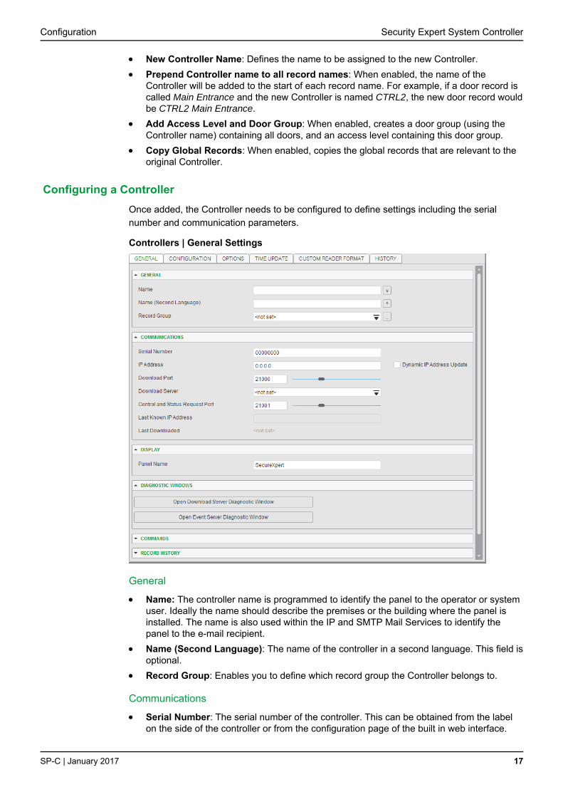
Configuring a Controller
Once added, the Controller needs to be configured to define settings including the serial
number and communication parameters.
Controllers | General Settings
General
Name: The controller name is programmed to identify the panel to the operator or system user. Ideally the name should describe the premises or the building where the panel is installed. The name is also used within the IP and SMTP Mail Services to identify the panel to the e-mail recipient.
Name (Second Language): The name of the controller in a second language. This field is optional.
Record Group: Enables you to define which record group the Controller belongs to.
Communications
Serial Number: The serial number of the controller. This can be obtained from the label on the side of the controller or from the configuration page of the built in web interface.
Security Expert System Controller Configuration
18 SP-C | January 2017
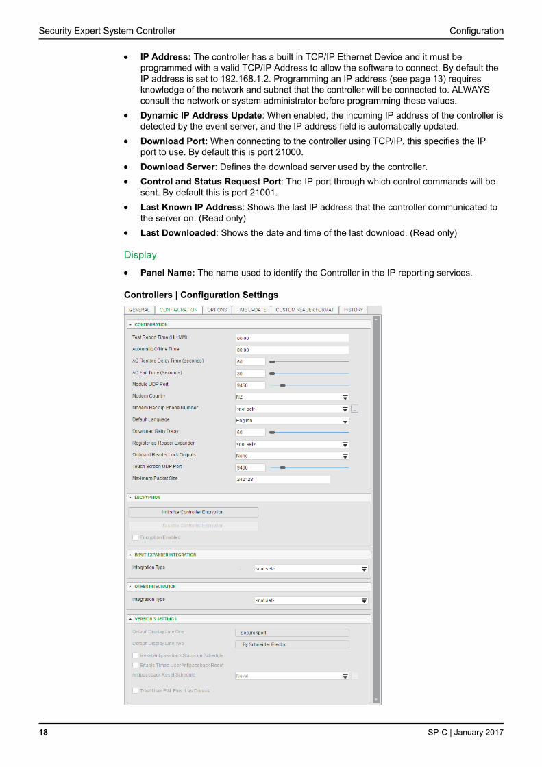
IP Address: The controller has a built in TCP/IP Ethernet Device and it must be programmed with a valid TCP/IP Address to allow the software to connect. By default the IP address is set to 192.168.1.2. Programming an IP address (see page 13) requires knowledge of the network and subnet that the controller will be connected to. ALWAYS consult the network or system administrator before programming these values.
Dynamic IP Address Update: When enabled, the incoming IP address of the controller is detected by the event server, and the IP address field is automatically updated.
Download Port: When connecting to the controller using TCP/IP, this specifies the IP port to use. By default this is port 21000.
Download Server: Defines the download server used by the controller.
Control and Status Request Port: The IP port through which control commands will be sent. By default this is port 21001.
Last Known IP Address: Shows the last IP address that the controller communicated to the server on. (Read only)
Last Downloaded: Shows the date and time of the last download. (Read only)
Display
Panel Name: The name used to identify the Controller in the IP reporting services.
Controllers | Configuration Settings
Configuration Security Expert System Controller
SP-C | January 2017 19
Configuration
Test Report Time (HH:MM): The test report time, in conjunction with the Test Report Time is Periodic option, sets the time of the day or the period that the test report trouble input activates. When the Test Report Time is Periodic option is enabled, the time programmed will be used as a period between reports in hours and minutes, else it is treated as a time of day.
Automatic Offline Time: Allows the panel to update the users and other offline parameters on all intelligent modules at a set time of the day.
AC Restore Delay Time (seconds): The AC Restore time allows the installer to program a time that AC must be present for after a AC Failure before restoring the AC Failure Trouble Input. Set this to a larger value for locations that experience frequent but short interruptions in power or that operates on a generator frequently. This setting is only relevant to older hardware which is supplied by an AC power source.
AC Fail Time (Seconds): The AC Failure time allows the installer to program a time that AC mains voltage must have failed before activating the AC Failure Trouble Input. Set this to a larger value for locations that experience frequent but short interruptions in power or that operates on a generator frequently. This setting is only relevant to older hardware which is supplied by an AC power source.
Module UDP Port: This is the UDP port that all Ethernet enabled modules will communicate with the Security Expert controller over. If this port is changed all modules will also need to be changed.
Modem Country: The onboard modem must be configured for the region that the controller is being installed in to ensure proper operation.
Modem Backup Phone Number: If Ethernet communication fails, the modem will dial this number to report events.
Default Language: The controller supports multiple languages on the keypad and the serial event printers. The language selected here will be the default language for users who have no language selected and also for any events.
Download Retry Delay: Defines the frequency (in seconds) at which the software sends programming updates to the controller.
Register as Reader Expander: Used for programming the onboard reader. The onboard reader is programmed as and treated by the system as if it were a reader expander connected on the module network. This setting defines the address at which the onboard reader will be registered and must be distinct from any physical reader expanders connected to the module network.
Onboard Reader Lock Outputs: Defines the output that will be activated upon successful door access. If set to none, the lock output (if any) programmed under the associated reader expander will be used.
Touchscreen UDP Port: The UDP port that a touchscreen will communicate over.
Encryption
Initialize Controller Encryption: Enables encryption of the messages sent between the controller and the Security Expert server. Selecting this option performs a one-off process that randomly generates and begins using a 256 bit AES encryption key. Using an RSA algorithm, this key is exchanged and stored in both the controller and the Security Expert database.
Disable Controller Encryption: Instructs the software to stop using encryption. To avoid encryption being disabled accidentally or maliciously, this option will NOT change the encryption setting in the controller itself. To stop the controller from using encryption it must be hardware defaulted.
Encryption Enabled: Read only field that indicates if encryption is enabled.
Security Expert System Controller Configuration
20 SP-C | January 2017
Elevator HLI
Elevator HLI Type: Defines the Elevator HLI the controller is used for. Choose from:
KONE
Primary Port: Defines the Primary Port used by the KONE controller.
Secondary Port: Defines the Secondary Port used by the KONE controller.
Primary IP Address: Defines the Primary IP Address of the KONE controller.
Secondary IP Address: Defines the Secondary IP Address of the KONE controller.
Default DOP Source Floor Group: A DOP Source Group defines the floors that
require a valid card read before access is granted. This should be assigned to a floor
group containing all accessible floors with access restricted by the DOPs
programming.
Default DOP Destination Floor Group: A DOP Destination Group defines the floors
that require a valid card read before access is granted. This should be assigned to a
floor group containing all accessible floors with access restricted by the DOPs
programming.
Default COP Destination Floor Group: A COP Destination Group defines the floors
that require a valid card read before access is granted. This should be assigned to a
floor group containing all accessible floors with access restricted by the COPs
programming.
Default DOP Disconnection Source Floor Group: A Disconnected Source Group
specifies the default settings for the DOPs during a communication failure. For
security reasons, this should be set to a floor group containing no floors to prevent
elevator access during this time.
Default DOP Disconnection Destination Floor Group: A Disconnected Destination
Groups specifies the default settings for the DOPs during a communication failure. For
security reasons, this should be set to a floor group containing no floors to prevent
elevator access during this time.
Default COP Disconnection Destination Floor Group: A Disconnected Destination
Groups specifies the default settings for the COPs during a communication failure. For
security reasons, this should be set to a floor group containing no floors to prevent
elevator access during this time.
Elevator HLI Debug: When enabled all HLI packets sent and received via Ethernet
are viewable using a telnet terminal. To achieve this, enable the option and setup a
Serial Printer service on the controller. Once configured, open a telnet session to the
configured port. When packets are exchanged between the Security Expert Controller
and the KONE Controller, the data received is echoed to the telnet window. Although
some of the information is displayed in plain English and is able to help determine
whether the two controllers are communicating, much of the data requires a low level
understanding of the KONE protocol.
OTIS
Lowest Basement Floor: Defines the lowest physical underground floor that is
accessible by an elevator.
Schindler
Port System Primary IP: Defines the Primary IP address of the Schindler PORT
Technology Server that the controller communicates with.
Port System Secondary: Defines the Secondary IP address of the Schindler PORT
Technology Server that the controller communicates with.

Configuration Security Expert System Controller
SP-C | January 2017 21
Online Database Port: The Schindler system's online database port.
Call Interface Port: The Schindler system's call interface port.
Life Reporting Interface Port: The Schindler system's life reporting interface port.
Lowest Basement Floor: Defines the lowest physical underground floor that is
accessible by an elevator.
Default Floor Group: The floor group containing all of the Schindler floors.
Enable Call Interface: Enables the Schindler call interface.
Enable Life Reporting Interface: Enables the Schindler life reporting interface.
Enable Elevator HLI Debug: When enabled, debug messages are logged for
troubleshooting.
Site Code Formats: Defines the Site Code format of the cards sent to the PORT
Technology Server. You can define up to 32 site code formats.
Site Code: Defines the Site Code for cards used by Schindler.
Format: Defines the format of the card. This can be selected as HID, Hitag 1, HID
Corporate 1000 or Unknown Wiegand.
Sub Format: Defines the sub format for card conversion. This can only be used if the
format is set to Unknown Wiegand and is defaulted to 34bit.
Restart HLI: Enables you to restart the elevator HLI service.
Input Expander Integration
Integration Type: Defines the Input Expander integration the controller is used for. Choose
from:
Redwall
Port: Defines the UDP Port the Controller is connected to and uses to receive
Redwall event codes.
Module Integration Port: Defines the Module Integration Port used for
communication between the Redwall scanner and the Security Expert controller when
the scanner is acting as a Security Expert input expander. If this is not defined, it will
default to port 9451.
Enable Redwall Debug: Enables the logging of Redwall alarm codes.
Inovonics
Port: Defines the TCP port that the Controller is connected to and uses to receive
Inovonics event codes. This must be set to port 80.
Module Integration Port: Defines the UDP port that the integration uses to listen for
replies to requests from Security Expert. This must be set to port 9452.
Inovonics IP Address: The IP address of the ACG unit the Security Expert controller
is connected to.
Inovonics Password: The password used by the controller when it attempts to
access information from the ACG. The controller is required to login as an
administrator so ensure that the password entered is the administrator password used
for the ACG.
Version 3 Settings
This section is read-only and refers to the options that previously applied globally to a controller.

Security Expert System Controller Configuration
22 SP-C | January 2017
Controllers | Options Settings
Options
Test Report Time is Periodic: When enabled, the test report trouble input will be activated at the frequency defined by the Test Report Time. When disabled the test report trouble input will be activated at the specified time of day.
Weekly Test Report: When enabled, the test report is sent once a week based on the day of the week selected.
Day of the Week: Defines the day of the week that the weekly test report is sent on.
Troubles Requires Acknowledge: When enabled any trouble condition will be latched and remain active until a user logs in to the keypad and acknowledges the trouble condition.
Generate Input Restore On Test Report Input: When enabled the controller will generate a restore event for the trouble input test report input restoring. This occurs one minute after the trouble input has been activated.
Report Short Duration Module Communication Failure: When enabled, module communication failure trouble events are always generated.
Advance UL Operation: When enabled, the Security Expert system runs in UL compliance mode.
Misc Options
Enable Automatic Offline Download: When enabled the controller will automatically update offline configuration parameters to all intelligent (RDI2, RDE2) modules at the time programmed in the Offline User Update Time.
Modem Backup if IP Fails: When selected the controller will dial out through a modem if it cannot connect to the software via Ethernet. If the Ethernet connection is subsequently restored, the communication path will automatically switch back to Ethernet.
Backup Only Alarm Events: If the Ethernet link has failed and the controller is communicating with the software via the modem, then this option can be selected to only send reportable events via modem. This reduces the amount of traffic and improves the response time. When the Ethernet link is restored ALL stored events are sent via Ethernet so this option does not mean that any events will be lost.
Invert Controller Tamper Input: When enabled the controller will invert the module tamper input allowing a normally open (door closed) tamper switch to be used. This setting is only relevant to older hardware which includes an onboard tamper input.

Configuration Security Expert System Controller
SP-C | January 2017 23
Log All Access Level Events: When enabled the controller will generate events including the reason a user was denied access if they do not have the required access rights.
Do Not Wait for Dial Tone When Modem Dials Out: When enabled, modem dialing occurs even when no dial tone is detected.
Controllers | Time Update Settings
Automatically Synchronize with an Internet Time Server: Select this option to
automatically synchronize the controller with an internet time server.
Primary SNTP Time Server: IP address of the primary SNTP time server for the controller to update its time from.
Secondary SNTP Time Server: IP address of the secondary SNTP time server for the controller to update its time from should it not be able to connect to the primary SNTP server.
Time Zone: The current time zone that should be assigned to the controller. Offset from GMT.
When using a Time Server, the time provided is always in UTC (Coordinated Universal Time) which has no time zone and is not subject to any daylight saving time rules. This means that you must correctly configure the Time Server, the time zone that the controller is operating in, and the daylight savings settings for NTP to work correctly. Failure to configure any of these things will result in the time being inaccurate.
Security Expert System Controller Configuration
24 SP-C | January 2017
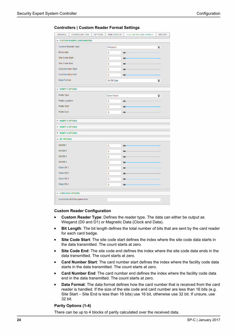
Controllers | Custom Reader Format Settings
Custom Reader Configuration
Custom Reader Type: Defines the reader type. The data can either be output as Wiegand (D0 and D1) or Magnetic Data (Clock and Data).
Bit Length: The bit length defines the total number of bits that are sent by the card reader for each card badge.
Site Code Start: The site code start defines the index where the site code data starts in the data transmitted. The count starts at zero.
Site Code End: The site code end defines the index where the site code data ends in the data transmitted. The count starts at zero.
Card Number Start: The card number start defines the index where the facility code data starts in the data transmitted. The count starts at zero.
Card Number End: The card number end defines the index where the facility code data end in the data transmitted. The count starts at zero.
Data Format: The data format defines how the card number that is received from the card reader is handled. If the size of the site code and card number are less than 16 bits (e.g. Site Start – Site End is less than 16 bits) use 16 bit, otherwise use 32 bit. If unsure, use 32 bit.
Parity Options (1-4)
There can be up to 4 blocks of parity calculated over the received data.

Configuration Security Expert System Controller
SP-C | January 2017 25
Parity Type: The parity type defines the method of calculating the parity for the block. This is either Even or Odd Parity.
Parity Location: The parity location defines where the location of the parity bit in the received data.
Parity Start: Defines where the location of the parity block starts in the received data.
Parity End: Defines where the location of the parity block ends in the received data.
Bit Options (1-4)
Set Bit: A set bit defines a location in the received data that must always be set (or a logical '1'). The set bit defines where the location of the bit in the received data.
Clear Bit: A clear bit defines a location in the received data that must always be cleared (or a logical '0'). The clear bit defines the location of the bit in the received data.
Card Data Options
Card Data AES Encryption Key: Salto SALLIS cards can be encoded with site/card information via the Schneider Electric Encoder Client. This defines the decryption key used with these cards. Please contact Schneider Electric for additional information. This option sets the Card Data AES Encryption Key for all reader ports associated with the Controller.
Addressing Modules Traditionally the network address of a module has been set using a bank of DIP Switches
located on each individual module. The DIN Rail modules enable addresses to be configured
electronically via the Security Expert software.
i
The factory default address of all DIN Rail mount modules is 254 and without
changing this address they will not be able to register with the Controller.
To change the network address of a module:
1. Ensure the Controller is correctly powered and is communicating with the Security Expert software. Refer to Security Expert software documentation for more information about the software configuration.
2. Connect the module(s) that require addressing to the module network. Make sure that the Power light on each module is on and that the Status light begins flashing rapidly.
3. Allow some time for the module(s) to attempt to register with the Controller.
If the module has the default address of 254 or has the same address as another
module, the Fault light will begin flashing at 1 second intervals.
If the module has been previously addressed and is not a duplicate then it will
succeed in registering and the Status light will begin flashing at 1 second intervals.
4. Once all modules have completed the registration process (successful or not), open the Auto-addressing window in the software by right clicking on the Controller and selecting Module Addressing.
The Module - Addressing window opens:

Security Expert System Controller Configuration
26 SP-C | January 2017
5. If the address can be changed electronically this is indicated in the Address can be changed column and the selector in the Address column is enabled. The Update and Find options will also be enabled. If it is not clear which module is which, click Find to instruct the respective module to flash its Status light for the specified period of time. Modules can also be identified by comparing the serial number on the label with that shown in the software. Ensure that you are clear which module is which before assigning addresses to them.
6. Enter an address for the relevant module(s) by selecting an option from the Address column. When an address has been selected but has not yet been updated on the module, it is shown in red. Modules can be updated individually by clicking the option in the Update column, or all at once using the Update All button. Allow about 5 seconds per module for the new address to be sent and registered.
7. Click Refresh to update the list and display the new addresses. The addresses change from red to grey to show that they have been read back from the Controller.
If the address has not changed, check the module is online and communicating and
that is has finished attempting to register.
If the address has changed but the module is not shown as registered, check the
address is in the valid address range and that it is not a duplicate of another modules
address.
Once all modules are online and registered with the desired addresses, the addressing process is complete.

Door Access Control Security Expert System Controller
SP-C | January 2017 27
The Controller provides access control functionality onboard without the requirement for
additional hardware. The Controller allows the connection of two Wiegand devices to control
two doors (entry or exit only) or it can be configured in multiplex mode to allow four Wiegand
devices controlling two doors giving the flexibility of entry and exit readers. Alternately the two
reader ports can be independently configured to connect RS485 based readers.
Warning:
The card reader must be connected to the Controller port using a shielded cable.
Always refer to the card reader manufacturer for detailed installation guidelines.
The shield connection must only be connected at one end of the cable in the metallic enclosure (frame grounded).
Do not connect the shield to a V- connection on the Controller.
Do not join the shield and black wires at the reading device.
Do not connect the shield to any shield used for isolated communication.
All Security Expert Readers are shipped with single LED mode set as default.
Wiegand Card Reader Connection The following diagram shows the connection of a standard Wiegand Reader with the
Controller controlling an access door in entry or exit mode (2 doors, 2 readers).
Shield is frame grounded at
one point
Shielded Cable
RED
BLACK
GREEN
WHITE
ORANGE
BROWN
BLUE
YELLOW
SHIELD
N/R
N/R
Shield notconnected
V+V-Z4 V- Z3 Z2 V- Z1BZ L1 NB NA
1 2
3 4
5 6
7 8
9 0
XD1/ D0/
Card Reader Connection
Door Access Control

Security Expert System Controller Door Access Control
28 SP-C | January 2017
Multiplex Wiegand Card Reader Connection Multiplex reader mode allows the connection of 4 Wiegand reading devices controlling two
doors each with entry/exit readers.
In multiplex mode, the secondary reader has all connections wired to the same port as the
primary card reader with the DATA 1 connection wired to the opposite reader connection
DATA 1 input.
Shield is frame grounded at
one point
Shielded Cable
Shielded Cable
RED
BLACK
GREEN
WHITE
ORANGE
BROWN
BLUE
YELLOW
SHIELD
N/R
N/R
RED
BLACK
GREEN
SHIELD
WHITE
ORANGE
BROWN
BLUE
YELLOW
N/R
N/R
Shield notconnected
V+V-Z4 V- Z3 Z2 V- Z1BZ L1 NB NABZ L1D1/ D0/NB NA
D1/ D0/
1 2
3 4
5 6
7 8
9 0
X
Multiplex Wiegand Card Reader Connection
RS-485 Reader Locations
��UL
ULC
RS-485 operation has not been investigated by UL/ULC for Access Control
applications
As two RS-485 readers can be connected to the same RS-485 reader port, the configuration
of the green and orange wires is used to uniquely identify the reader and determine which is
the entry reader, and which is the exit reader.
Location Configuration
Entry Green and orange wires not connected.
Exit Green and orange wires connected together.

Door Access Control Security Expert System Controller
SP-C | January 2017 29
RS-485 Card Reader Connection (Entry Only) The following diagram shows the connection of a single RS-485 Reader connected in entry
only mode.
Shield is frame grounded at
one point
Shielded Cable
RED
BLACK
GREEN
WHITE
ORANGE
BROWN
BLUE
YELLOW
VIOLET
N/R
N/R
Shield notconnected
V+V-Z4 V- Z3 Z2 V- Z1BZ L1 D1/NB
D0/NA
SHIELD
1 2
3 4
5 6
7 8
9 0
X
Single RS-485 Reader configured for Entry Only
When the green and orange wires are not connected together, the reader defaults to an entry
reader.
RS-485 Card Reader Connection (Entry/Exit) The following diagram shows the connection of two RS-485 Readers connected to provide an
entry/exit configuration.
Shield is frame grounded at
one point
Shielded Cable
Shielded Cable
RED
BLACK
GREEN
WHITE
ORANGE
BROWN
BLUE
YELLOW
SHIELD
N/R
N/R
RED
BLACK
GREEN
SHIELD
WHITE
ORANGE
BROWN
BLUE
YELLOW
N/R
N/R
Shield notconnected
VIOLET
VIOLETENTRY
EXITV+V-Z4 V- Z3 Z2 V- Z1BZ L1 D1/
NBD0/NA
1 2
3 4
5 6
7 8
9 0
X
Two RS-485 Readers configured for entry and exit
The exit reader has the green and orange wires connected together.

Security Expert System Controller Door Access Control
30 SP-C | January 2017
Door Contact Connection The Controller allows the connection of up to 4 contacts for monitoring and controlling access
control doors. Each input on the Controller can be used for either the door function that is
automatically assigned or as a normal input on the system. The following example shows the
connection of a normally closed door position monitoring contact to monitor the Open, Closed,
Forced and Alarm conditions of the door.
V+V-
Z4V-
Z3Z2
V-Z1
N.C. Input Contact
N.C. Input Contact
N.O. Input Contact
N.O. Input Contact
1K
1K
1K
1K
1K
1K 1K
1K
Door Contact
Bond Sense
REN Input
REX Input
Door Contact Connection
Inputs 1-4 and 5-8 can operate as either general purpose inputs or as onboard reader inputs.
If used as general purpose inputs, make sure that these inputs are not defined in the onboard
reader set up.
Input Access Control Function Default Setting
Input 1 Door Contact, Port 1 Door Contact, Port 1
Input 2 REX Input, Port 1 REX Input, Port 1
Input 3 Bond Sense, Port 1 General Purpose Input
Input 4 REN Input, Port 1 General Purpose Input
Input 5 Door Contact, Port 2 Door Contact, Port 2
Input 6 REX Input, Port 2 REX Input, Port 2
Input 7 Bond Sense, Port 2 General Purpose Input
Input 8 REN Input, Port 2 General Purpose Input
When connected, the REX Input can be programmed to operate regardless of the door
contact state. The REX input can also be programmed to recycle the door alarm time to
prevent nuisance alarms when the door is held open to permit longer entry times.

Door Access Control Security Expert System Controller
SP-C | January 2017 31
Lock Output Connection The Controller provides a connection for an electric strike lock with full monitoring of the lock
circuit for tamper and over current/fuse blown conditions. The door lock monitoring can be
disabled if it is not required.
The lock output is shared with the bell/siren function as shown in the diagram below. You can
select another output for the lock control (Relay 1 (CP001:03) or Relay 2 (CP001:04)) if the
bell/siren function is required. To use the lock outputs in conjunction with the onboard reader
module, the Lock output for the door associated with the reader port must be configured to be
the desired lock output on the Controller. This is not configured by default.
LEDV+V-
Z4V-
Z3Z2
V-Z1
1K5 OHM
B-NO
B+NC
NOCO
MNC
COM
Lock Output Connection
When using a door with an Entry and Exit Reader, the lock output should be connected to the
Bell (CP001:01), and the swap lock option for the second reader input should be enabled to
allow the reader LEDs to display the correct status.
i
The Bell output current must not exceed 1.6A or electronic shutdown will be
engaged. Ensure the devices connected to the outputs are within the limits as
described in the Technical Specifications (see page 45).

Security Expert System Controller Door Access Control
32 SP-C | January 2017
Programming the Onboard Reader The onboard reader is programmed in exactly the same way as any other reader module is. It
can be thought of as if it were a normal reader expander module on a separate circuit board.
By default the onboard reader is disabled. To enable it, configure the address at which you
want it to register using the Security Expert software (under the Sites > Controllers
programming tab). Note that any physical reader expander module that is connected with the
same address will be treated as a duplicate and will fail to register so care should be taken to
ensure the address is unique.
The onboard reader uses inputs 1-4 and 5-8 as its door contact, REX, bond sense and REN
inputs respectively. Any of these inputs that are not configured for use with the onboard
reader may be used as general purpose inputs. If the onboard reader is enabled and you wish
to use some of these as general inputs, you will need to disable the associated function input
in the Reader Expander programming section of the Security Expert software.
��UL
ULC
REX and REN devices must be Listed to UL 294 for UL installations and
CAN/ULC-S319 for ULC installations, and be compatible with the system.
The default settings are shown in the following table:
Input Access Control Function Default Setting
Input 1 Door Contact, Port 1 Door Contact, Port 1
Input 2 REX Input, Port 1 REX Input, Port 1
Input 3 Bond Sense, Port 1 General Purpose Input
Input 4 REN Input, Port 1 General Purpose Input
Input 5 Door Contact, Port 2 Door Contact, Port 2
Input 6 REX Input, Port 2 REX Input, Port 2
Input 7 Bond Sense, Port 2 General Purpose Input
Input 8 REN Input, Port 2 General Purpose Input

Door Access Control Security Expert System Controller
SP-C | January 2017 33
Reader Expander Properties
The controller's onboard reader ports support both an RS-485 and Wiegand reader interface
allowing both Wiegand and Schneider Electric 485 readers to be configured.The option is
available to select the onboard reader's port type to either Wiegand or Schneider Electric 485
from the Reader Expander menu.
Setting the Onboard Reader's Port Type

Security Expert System Controller Inputs
34 SP-C | January 2017
The Controller has 8 onboard inputs for monitoring the state of devices such as magnetic
contacts, motion detectors and temperature sensors. Devices connected to these inputs can
be installed to a maximum distance of 300m (1000ft) from the Controller when using 22 AWG.
Inputs can be programmed using the Security Expert software. Inputs CP001:01 to CP001:08
represent the Controller's onboard inputs. Additional inputs are supported through the use of
expansion modules.
The Controller supports normally opened and normally closed configurations with or without
EOL resistors. When using an input with the EOL resistor configuration, the Controller
generates an alarm condition when the state of an input is toggled and generates a tamper
alarm condition when a wire fault (short circuit) or a cut (tampered) in the line occurs. Inputs
default to require the EOL resistor configuration.
N.C Input Contact
N.C Tamper 1K 1K
V+V-
Z4V-
Z3Z2
V-Z1
EOL Resistor Input Configuration
i
Inputs 1-4 and 5-8 can operate as either general purpose inputs or as onboard
reader inputs. If used as general purpose inputs you must ensure that they are not
defined in the onboard reader set up.
Each input can use a different configuration. To program a large number of inputs with a
certain configuration, use the multiple selection feature within the Security Expert software.
When using the No Resistor configuration, the Controller only monitors the opened and closed
state of the connected input device generating the alarm and seal conditions.
N.C Input Contact
V+V-
Z4V-
Z3Z2
V-Z1
No EOL Resistor Input Configuration
Inputs

Inputs Security Expert System Controller
SP-C | January 2017 35
Resistor Value Options When using the EOL resistor configuration, the EOL resistor option must be configured based
on the site requirements. Note these resistor options are supported on the Controller but not
all resistor options are supported on all Security Expert field modules.
Value 1 Value 2 Monitored Status
1k 1k Open, Closed, Tamper, Short
1k No Resistor Open, Closed
<5K7 No Resistor Open, Closed
No Resistor No Resistor Open, Closed
2k2 6k8 Open, Closed, Tamper, Short
10k 10k Open, Closed, Tamper, Short
2k2 2k2 Open, Closed, Tamper, Short
4k7 2k2 Open, Closed, Tamper, Short
4k7 4k7 Open, Closed, Tamper, Short
5k6 5k6 Open, Closed, Tamper, Short
Trouble Inputs Each Controller can monitor up to 64 local trouble inputs. Trouble inputs are used to monitor
the status of the Controller and in most cases are not physically connected to an external
input. These can then be used to report a message to a monitoring station, remote computer,
keypad or siren.
The following table details the trouble inputs that are configured in the Controller. The trouble
type and group define the trouble that is generated by the trouble input when it is activated.
Input Number Description Type Group
CP001:01 Reserved - -
CP001:02 12V supply failure Power Fault General
CP001:03 Reserved - -
CP001:04 Real Time Clock Not Set RTC/Clock Loss General
CP001:05 Service Report Test - -
CP001:06 Service Report Failure to
Communicate
Reporting Failure General
CP001:07 Phone Line Fault Phone Line Lost General
CP001:08 Auxiliary Failure Power Fault General
CP001:09 Bell Cut/Tamper Bell/Output Fault General
CP001:10 Reserved - -
CP001:11 Bell Current Overload Bell/Output Fault General
CP001:12 Reserved - -

Security Expert System Controller Inputs
36 SP-C | January 2017
Input Number Description Type Group
CP001:13 Module Communication Module Loss System
CP001:14 Module Network Security Module Security System
CP001:15 Reserved - -
CP001:16 Reserved - -
CP001:17 Reserved - -
CP001:18 Reserved - -
CP001:19 Reserved - -
CP001:20 Ethernet Link Lost Hardware Fault System
CP001:21 Reserved - -
CP001:22 ModBUS Communication
Fault
Hardware Fault System
CP001:23 Security Expert System
Remote Access
Hardware Fault System
CP001:24 Installer Logged In Hardware Fault System
CP001:25 Reserved - -
CP001:26 Reserved - -
CP001:27 Reserved - -
CP001:28 Reserved - -
CP001:29 System restarted Hardware Fault System
CP001:30 PoE Connection Lost
(PoE model only)
Power Fault General
CP001:31 Output Over-Current
Failure (PoE model only)
Power Fault General
CP001:32 3G Modem Link Lost Hardware Fault System
CP001:33 Controller Group Link Lost Hardware Fault System
| | | | | | | |
CP001:64 Reserved - -

Outputs Security Expert System Controller
SP-C | January 2017 37
The Controller has 7 onboard outputs. Outputs are used to activate sirens, bells, warning
devices, control lighting and doors. The first output on the Controller has a special hardware
design that allows it to monitor for fault conditions and is ideally suited to driving sirens or
warning devices.
Bell/Siren Output The + and - terminals of the Bell output (CP001:01) are used to power bells, sirens or any
devices that require a steady voltage output. The bell output supplies 12VDC upon alarm and
supports one 30-watt siren. The bell output uses an electronically fused circuit and
automatically shuts down under fault conditions.
Connecting a Piezo siren may result in a dull noise being emitted. This is caused by residual
current from the monitoring circuit. To prevent this occurring, connect 2 1K resistors in
parallel.
+
-
12VDC siren warning device
1k Resistors
B-NO
B+NC
NOCOM
NCCOM
Bell Siren Connection
If the load on the bell terminals returns to normal, the Controller reinstates power to the bell
terminals on the next transition of the output.
i
When the bell output is not used, the appropriate trouble input (see page 35) will be
activated. This can be avoided by connecting a 1K resistor (provided in the
accessory bag) across the bell output. If the bell is not being used for another
function, and the trouble input is not programmed in the system, a resistor is not
required.
Outputs

Security Expert System Controller Outputs
38 SP-C | January 2017
Relay Outputs The Relay Outputs (CP001:03 and CP001:04) on the Controller are Form C relays having
normally open and normally closed contacts. These outputs can be used to activate larger
relays, sounders and lights, etc.
LEDV+V-
Z4V-
Z3Z2
V-Z1
1K5 OHM
B-NO
B+NC
NOCO
MNC
COM
Example Relay Connection
Warning: The Relay outputs can switch to a maximum capacity of 7A. Exceeding
this amount will damage the output.
Reader Outputs If readers are not attached to the reader ports then the Reader 1 L1 and BZ, and the Reader 2
L1 and BZ outputs can be used as general purpose outputs. These can be controlled by
assigning the RDxxxGreen R1, RDxxx Beeper R1, RDxxxGreen R2 and RDxxx Beeper R2
outputs of whichever reader module has been configured as the onboard reader module.
These are open drain outputs which switch to the V- reference.
BZL1
D1DO
LED
V+V-
Z4V-
Z3Z2
V-Z1
1K5 OHM
Open Drain Reader Outputs
Warning: The reader outputs can switch to a maximum capacity of 50mA.
Exceeding this amount will damage the output.

Hardware Configuration Security Expert System Controller
SP-C | January 2017 39
Defaulting a Controller The Controller can be set back to factory default using the following procedure. This resets all
internal data and event information, and turns off network encryption.
1. Remove power from the Controller by disconnecting the 12V DC input.
2. Connect a wire link between Reader 2 D0 input and Reader 2 L1 output.
3. Power up the Controller.
4. Once the Controller has started and the Status light is flashing, remove the wire link from the Reader 2 connector. The system will now be defaulted with all programming and settings returned to factory configuration.
BZ L1 D1/NB
READER 2
D0/NA
i
Defaulting the Controller does not reset the IP address. Refer to Setting the IP
Address (see page 13) for instructions on how to reset the address.
Temporarily Defaulting the IP Address The Controller can have its IP address temporarily set to 192.168.111.222 by using the
following procedure. This resets the IP address for as long as power is applied but will not
save the change permanently. Once the link is removed and power is cycled to the unit, the
previously configured IP address is used again. This means that if the currently configured IP
address is unknown, you are able to connect to the web interface to view and/or change it.
1. Remove power from the Controller by disconnecting the 12V DC input.
2. Connect a wire link between Reader 1 D0 input and Reader 1 L1 output.
3. Power up the Controller.
4. When the Controller starts up it will use the following settings:
IP address : 192.168.111.222
Gateway : 192.168.111.254
Net Mask : 255.255.255.0
DHCP : disabled
5. Connect to the web interface by typing 192.168.111.222 into the address bar of your web browser, and view or change the IP address as required.
BZ L1 D1/NB
READER 1
D0/NA
Hardware Configuration
Security Expert System Controller LED Indicators
40 SP-C | January 2017
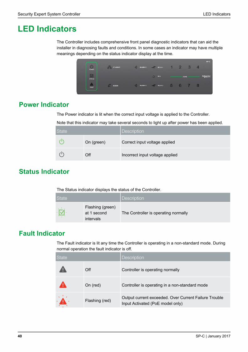
The Controller includes comprehensive front panel diagnostic indicators that can aid the
installer in diagnosing faults and conditions. In some cases an indicator may have multiple
meanings depending on the status indicator display at the time.
Power Indicator The Power indicator is lit when the correct input voltage is applied to the Controller.
Note that this indicator may take several seconds to light up after power has been applied.
State Description
On (green) Correct input voltage applied
Off Incorrect input voltage applied
Status Indicator
The Status indicator displays the status of the Controller.
State Description
Flashing (green)
at 1 second
intervals
The Controller is operating normally
Fault Indicator The Fault indicator is lit any time the Controller is operating in a non-standard mode. During
normal operation the fault indicator is off.
State Description
Off Controller is operating normally
On (red) Controller is operating in a non-standard mode
Flashing (red)
Output current exceeded. Over Current Failure Trouble
Input Activated (PoE model only)
LED Indicators

LED Indicators Security Expert System Controller
SP-C | January 2017 41
Ethernet Link Indicator The Ethernet indicator shows the status of the Ethernet connection.
State Description
On (green)
Valid link with a hub, switch or direct connection to a
personal computer detected
Flashing (green) Data is being received or transmitted
Off Ethernet cable not connected, no link detected
Modem Indicator The Modem indicator shows the status of the onboard modem.
State Description
On (green) Modem has control of telephone line
Off Modem is not active
Reader Data Indicators The R1 and R2 indicators display the status of the data being received by the onboard
readers.
State Description
Short flash (red) A SHORT flash (<250 Milliseconds) will show that data
was received but was not in the correct format.
Long flash (red) A LONG flash (>1 Second) indicates that the unit has
read the data and the format was correct.
Bell Indicator The Bell indicator shows the status of the bell output and the over current or circuit fault
conditions.
State Description
Off Bell is connected, output is OFF
On (green) Bell is ON
Single flash
(green) Bell is ON, the circuit is in over current protection
Two flashes
(green)
Bell is OFF, the circuit to the siren/bell is cut, damaged or
tampered
Security Expert System Controller LED Indicators
42 SP-C | January 2017
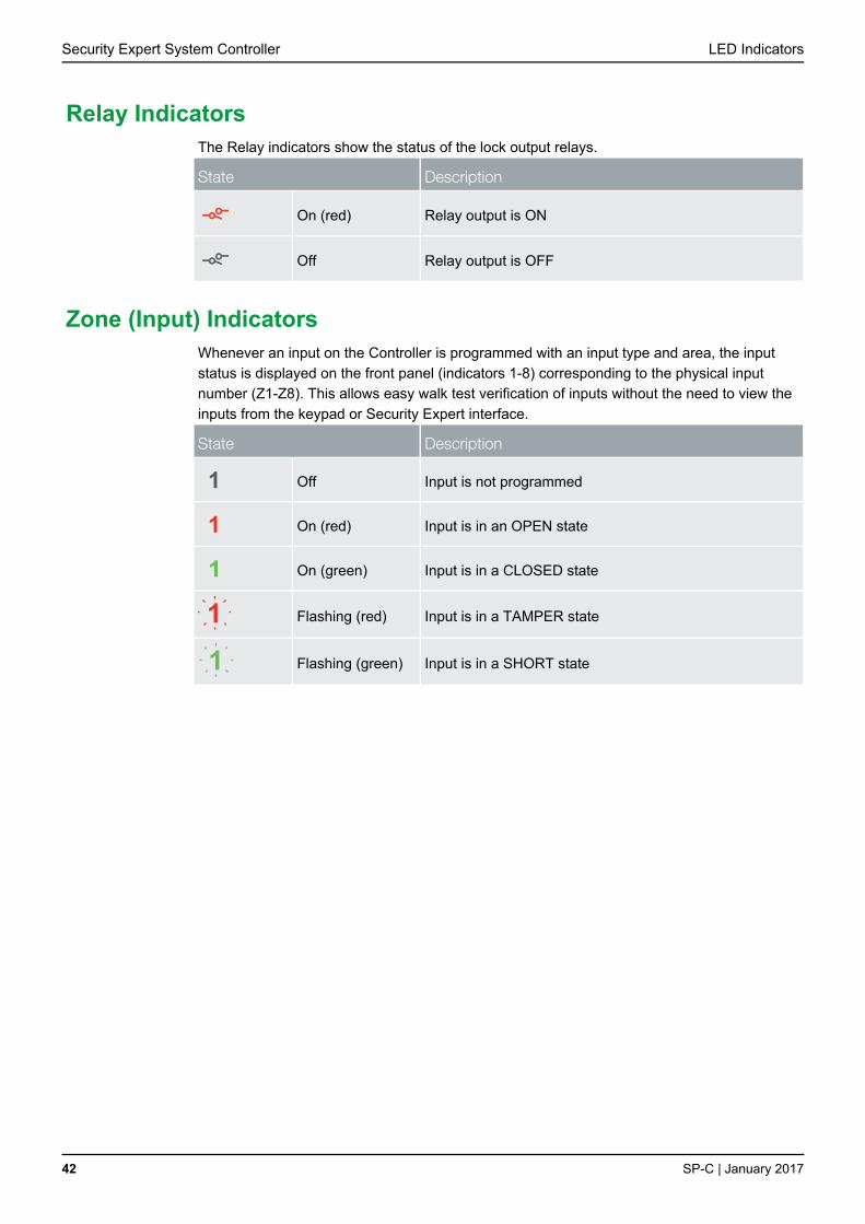
Relay Indicators The Relay indicators show the status of the lock output relays.
State Description
On (red) Relay output is ON
Off Relay output is OFF
Zone (Input) Indicators Whenever an input on the Controller is programmed with an input type and area, the input
status is displayed on the front panel (indicators 1-8) corresponding to the physical input
number (Z1-Z8). This allows easy walk test verification of inputs without the need to view the
inputs from the keypad or Security Expert interface.
State Description
1
Off Input is not programmed
1
On (red) Input is in an OPEN state
1
On (green) Input is in a CLOSED state
1
Flashing (red) Input is in a TAMPER state
1
Flashing (green) Input is in a SHORT state

Mechanical Diagram Security Expert System Controller
SP-C | January 2017 43
The mechanical diagram shown below outlines the essential details needed to help ensure
the correct installation of the Controller.
Input Status
Inputs 1 to 4Reader Port
RS-485 Input
Reader Port
Ethernet Interface
Status IndicatorsBell/Relay Outputs
Inputs 5 to 8
12VDC Input
Status Indicators
Panel Modem Interface
Backup Connection
Mechanical Diagram

Security Expert System Controller Mechanical Layout
44 SP-C | January 2017
The mechanical layout shown below outlines the essential details needed to help ensure the
correct installation of the Controller.
156.8mm
143.5mm
36.4mm
90mm
90mm
156.8mm
Controller Front
44.1mm
Controller Back
Mechanical Layout

Technical Specifications Security Expert System Controller
SP-C | January 2017 45
The following specifications are important and vital to the correct operation of the Controller.
Failure to adhere to the specifications will result in any warranty or guarantee that was
provided becoming null and void.
Operating Voltage 11-14V DC
Operating Current 120mA (typical)
DC Output (Auxiliary) 10.45-13.85VDC 0.7A (typical) electronic shutdown at 1.1A
Bell DC Output (Continuous) 10.4-13.4VDC 8 Ohm 30W Siren or 1.1A (Typical) Electronic
Shutdown at 1.6A.
Bell DC Output (Inrush) 1500mA
Total Combined Current* 3.4A (max)
Electronic Disconnection 9.0VDC
Communication (Ethernet) 1 10/100Mbps Ethernet communication link
Communication (Serial) 1 RS-485 communication interface port for module
communication
2 RS-485 communication interface ports for reader
communication
Communication (Modem) 1 2400bps modem communication
Readers (Standard mode) 2 Wiegand readers providing one entry/exit door or two
entry/exit only doors
Readers (Multiplex mode) 4 Wiegand readers (connected in multiplex mode) providing
any combination of entry or exit for two doors
Readers (RS-485 mode)** 4 RS-485 capable readers (two per port) providing two
entry/exit doors
Inputs (System Inputs) 8 high security monitored inputs
Outputs 4 50mA (max) open collector outputs for reader LED and
beeper or general functions
Relay Outputs 2 FORM C relays - 7A 250V max resistive/inductive
Operating Temperature 0˚-49˚C (32˚ - 122˚F)
Storage Temperature -10˚- 85˚C (14˚ - 185˚F)
Humidity 0%-93% non condensing, indoor use only (relative humidity)
Dimensions (L x W x H) 156 x 90 x 60mm (6.14 x 3.54 x 2.36")
Weight 376g (13.26oz)
*The Total Combined Current refers to the current that will be drawn from the external power
supply to supply the Controller and any devices connected to the Controller's outputs. The
Auxiliary outputs and Bell output are directly connected via electronic fuses to the N+ N- input
terminals, and the maximum current is governed by the trip level of these fuses.
**Applies to models equipped with a 3G modem.
***Each reader port supports either Wiegand or RS485 operation but not both at the same
time. If combining Wiegand and RS-485 technologies, they must be connected on separate
ports.
The size of conductor used for the supply of power to the unit should be adequate to prevent
voltage drop at the terminals of no more than 5% of the rated supply voltage.
Technical Specifications

Security Expert System Controller Technical Specifications
46 SP-C | January 2017
Current and Validation Example The example shown below refers to the specifications needed to help ensure the correct
installation of a Security Expert Controller. Specifications should be validated to ensure that
individual maximum currents and total combined current are not exceeded.
Example
External Devices Connected to Panel
4 EDGE PIR Motion Detectors (Z1 to Z4) connected on AUX1 Output
4 EDGE PIR Motion Detectors (Z5 to Z8) connected on AUX2 Output
1 30W Siren (1.1A (1100mA) @ 13.8VDC)
Current Consumption
Total Combined Current before
shutdown
3.4A (3400mA)
Operating Current 120mA (Typical)
DC Output (AUX1) 4 EDGE PIR Motion Detectors @ 15mA each (Total 60mA)
DC Output (AUX2) 4 EDGE PIR Motion Detectors @ 15mA each (Total 60mA)
Siren on Bell Output 1.1A (1100mA)
Total Consumption 1.34A (1340mA)
Validation
Is the total DC Output (AUX1) current less or equal to 1.1A
(1100mA)?
Yes, it is 60mA
Is the total DC Output (AUX2) current less or equal to 1.1A
(1100mA)?
Yes, it is 60mA
Is the Bell current output less or equal to 1.1A (1100mA)? Yes, it is 1.1A (1100mA)
Is the total combined current less or equal to 3.4A
(3400mA)?
Yes, it is 1.34A (1340mA)

New Zealand and Australia Security Expert System Controller
SP-C | January 2017 47
The compliance label indicates that the supplier of the device asserts that it complies with all
applicable standards.
New Zealand and Australia

Security Expert System Controller European CE and EN 50131
48 SP-C | January 2017
European Standards
Conforms to European Union (EU) Low Voltage Directive (LVD) 73/23/EEC (amended by
93/68/EEC) and Electro-Magnetic Compatibility (EMC) Directive 89/336/EEC (amended by
92/31/EEC and 93/68/EEC). The CE mark indicates that this product complies with the
European requirements for safety, health, environmental and customer protection
This component was tested by the accredited testing laboratory No. 1172 of the company
TESTALARM Praha s.r.o. and met the requirements and conditions for full compliance with
EN50131 series of standards for equipment classification;
Security Grade 3
Environmental Class II
Equipment Class: Fixed
EN 50131-1:2006, EN 50131-3:2009, EN 50131-6:2008
Recognition class 2 (for readers without a keypad)
Recognition class 3 (for readers with a keypad)
Access class B
EN 50133-1:1998
Enclosures EN-DIN-24 and CAB-JMB-NOT, have been tested and certified to EN50131.
By design, the enclosures EN-DIN-10, EN-DIN-11, EN-DIN-12, EN-DIN-24-Attack,
EN-DIN-31, and CAB-FBY-NOT, comply with the EN50131 standards. Tamper protection
against removal of the cover as well as removal from mounting is provided by tamper switch.
Warning: Enclosures supplied by 3rd parties may not be EN50131-compliant, and
should not be claimed as such.
EN 50131
In order to comply with EN 50131-1 the following points should be noted:
Ensure for Grade 3 compliant systems, the minimum PIN length is set for 6 digits.
To comply with EN 50131-1 Engineer access must first be authorised by a user, therefore Installer codes will only be accepted when the system is unset. If additional restriction is required then Engineer access may be time limited to the first 30 seconds after the system is unset.
Reporting delay –Violation off the entry path during the entry delay countdown will trigger a warning alarm. The warning alarm should not cause a main alarm signal and is not reported at this time. It can be signaled locally, visually and or by internal siren type. If the zone is not disarmed within 30 seconds, the entry delay has expired or another instant is violated, the main alarm will be triggered and reported.
To comply with EN 50131-1 neither Internals Only on Part Set Zone Alarm nor Internals Only on Part Set Tamper Alarm should be selected.
To comply with EN 50131-1 Single Button Setting should not be selected.
To comply with EN 50131-1 only one battery can be connected and monitored per system. If more capacity is required a single larger battery must be used.
Anti Masking
To comply with EN 50131-1 Grade 3 for Anti Masking, detectors with a separate or
independent mask signal should be used and the mask output should be connected to
another input zone.
European CE and EN 50131

European CE and EN 50131 Security Expert System Controller
SP-C | January 2017 49
I.e. Use 2 input zones per detector. One zone input for alarm/tamper and one zone input for
masking.
To comply with EN 50131-1:
Do not fit more than 10 unpowered detectors per zone,
Do not fit more than one non-latching powered detector per zone,
Do not mix unpowered detectors and non-latching powered detectors on a zone.
To comply with EN 50131-1 the Entry Timer should not be programmed to more than 45
seconds.
To comply with EN 50131-1 the Bell Cut-Off Time should be programmed between 02 and 15
minutes.
EN 50131-1 requires that detector activation LEDs shall only be enabled during Walk Test.
This is most conveniently achieved by using detectors with a Remote LED Disable input.

Security Expert System Controller UL and ULC Installation Requirements
50 SP-C | January 2017
i
Only UL / ULC listed compatible products are intended to be connected to a UL /
ULC listed control system. This hardware is listed under SP-C.
UL/ULC Installation Cabinet Options UL/ULC Central Station Fire Monitoring, Central Station Alarm Installations
Cabinet Model UL/ULC Installation Listings
EN-DIN-24-ATTACK UL1610, UL1635, ULC-S304, ULC-S559
Electronic Access Control System Installations
��UL
ULC
All cabinet installations of this type must be located inside the Protected Area. Not
to be mounted on the exterior of a vault, safe or stockroom
Cabinet Model UL/ULC Installation Listings
EN-DIN-12 UL294, CAN/ULC-S319
EN-DIN-31 UL294, CAN/ULC-S319
EN-DIN-24 UL294, CAN/ULC-S319
EN-DIN-24-ATTACK UL294, CAN/ULC-S319
All cabinet internal covers and lid/doors must be connected to the cabinets main
ground point for electrical safety and static discharge protection.
Central Station Signal Receiver Compatibility List IP Receiver via Ethernet Port : ArmorIP Internet Monitoring Receiver. Serial interface to
be used with SIMS II version 1.3x central station automation system software and compatible receiving equipment as indicted in the SIMS II Appendix E UL Supplement.
CID Receiver via Onboard Modem: Any UL and ULC listed receiver that uses the Contact ID protocol.
ULC Compliance Requirements
CAN/ULC-S304-06 Auto Arming
Control units that support auto arming shall provide an audible signal throughout the protected area not less than 10 min prior to the auto arming taking place. The control unit shall allow authorised users to cancel the auto arming sequence and transmit such cancellation to the signal receiving centre with the identification of the authorised user that cancelled the action.
The following options must be enabled in the Security Expert System when using the Auto Arming feature. When the defer warning time is programmed to 10 minutes, the Output group will be activated 10 minutes before the system performs the Auto Arming in the associated Area.
UL and ULC Installation Requirements

UL and ULC Installation Requirements Security Expert System Controller
SP-C | January 2017 51
The Defer Output or Output Group must be programmed. Refer to the section Areas
| Outputs in the Security Expert Operator Reference Manual (227-1500-000) for
programming instructions.
The Defer Warning Time must be programmed to not less than 10 minutes. Refer to
the section Areas | Configuration in the Security Expert Operator Reference Manual
(227-1500-000).
The Defer Automatic Arming arming option must be enabled. Refer to the section
Areas | Options (2) in the Security Expert Operator Reference Manual
(227-1500-000).
Arming Signal
A bell or visual indicator used as an arming acknowledgement signal must be listed to a ULC security, signalling or fire standard. If intended to be mounted outside, it must be rated for outdoor use.
Double EOL Input Configuration
Only double EOL Input Configuration shall be used. Refer to the section Inputs (see page 34) of this manual and the section Inputs | Options in the Security Expert Operator Reference Manual (227-1500-000).
Multiplex System and Poll Time
The SP-C is compatible with the ArmorIP Internet Monitoring Receiver. Poll Time must be set to 40 seconds and the Grace Time must be set to 20 seconds.
In the Security Expert System, the reporting service must be configured to 40 seconds. The following options are required for the service selected as Report IP type:
The Log Polling Message option must be enabled. Refer to the section Report IP |
Options in the Security Expert Operator Reference Manual (227-1500-000).
The Poll Time must be programmed to 40 seconds. Refer to the Report IP | General
section in the Security Expert Operator Reference Manual (227-1500-000).
Central Station Signal Receiver
The common equipment of each signal receiving centre control unit shall be limited to 1000 alarm systems.
Number of attempts
In the event of unsuccessful communication, a digital alarm communicator transmitter shall make a minimum of 5 and a maximum of 10 attempts. Where the maximum number of attempts to complete the sequence is reached, an indication of the failure shall be made at the premises.
In the Security Expert System, the reporting service selected as Contact ID must have the number of attempts programmed to 5 attempts. The Dial Attempts option must be programmed. Refer to the section Contact ID | Settings in the Security Expert Operator Reference Manual (227-1500-000).
Check-In Time
DACT communication channel check-in time is not to exceed 24 hrs.
Trouble Input Service Test Report
The Test Report Time must be programmed. Refer to the section Controllers |
Configuration in the Security Expert Operator Reference Manual (227-1500-000).
The Generate Input Restore on Test Input option must be enabled. Refer to the
section Controller | Options in the Security Expert Operator Reference Manual
(227-1500-000).
The Test Report Time is Periodic option must be enabled. Refer to the section
Controller | Options in the Security Expert Operator Reference Manual
(227-1500-000).
Security Expert System Controller UL and ULC Installation Requirements
52 SP-C | January 2017
Primary Communication Channel
The first attempt to send a status change signal shall utilise the primary communication channel.
The Report IP and Contact ID services must be programmed and enabled within the Security Expert System, and the CID service must be set as the backup service. The following options are required:
The Contact ID Reporting Service must be enabled and the Service Mode must be
configured to start with the operating system.
Refer to the section Contact ID in the Security Expert Operator Reference Manual
(227-1500-000).
The Report IP Service must be enabled as the primary communication channel and
the Service Mode must be configured to start with the operating system. The
Reporting Protocol must be set to ArmorIP, and the Backup Service must be
configured to use the Contact ID Service.
Refer to the section Report IP in the Security Expert Operator Reference Manual
(227-1500-000).
All ULC S304 P3 applications must transmit signals simultaneously over both the
Contact ID Reporting Service and the Report ID Service. This will occur automatically
with the above programming.
Status Change Signal
An attempt to send a status change signal shall utilise both primary and secondary communication channels.
Local Annunciation if Signal Reporting Failure
Failure of the primary communication channel or secondary communication channel shall result in a trouble signal being transmitted to the signal receiving center within 240 seconds of the detection of the fault. Failure of either communication channel shall be annunciated locally within 180 seconds of the fault.
The following options must be enabled in the Security Expert System:
The Ethernet Link Failure Trouble Input must be programmed.
The Trouble Input Area must be armed. Refer to the section Trouble Inputs | Areas
and Input Types in the Security Expert Operator Reference Manual (227-1500-000).
The Log Modem Events to Event Buffer option must be selected in the Contact ID
Reporting Service.
Network and Domain Access
Neither the subscriber control unit nor the signal receiving centre receiver shall be susceptible to security breaches in general-purpose operating systems.
Network access policies should be set to restrict unauthorised network access and "spoofing" or "denial of service" attacks.
Ethernet Connections
All Ethernet network connections shall be installed within the same room as the equipment.
Encryption
For active communications channel security, encryption shall be enabled at all times.
The ArmorIP-E (UDP) protocol must be used and the Encryption Type must be set to AES-256.
The following options must be enabled for the Report IP service in the Security Expert System.
The Reporting Protocol must be set to ArmorIP (UDP) Encrypted. The AES key
must be set as specified by monitoring station.

UL and ULC Installation Requirements Security Expert System Controller
SP-C | January 2017 53
Refer to the section Report IP | General in the Security Expert Operator Reference
Manual (227-1500-000).
Server Configuration
Where a server is employed for control over network addressing, encryption or re-transmission, such shall be designed to remain in the "on state" at all times.
Communicators are not suitable for active communication channel security and medium or high risk applications unless such can be "on line" at all times, have a minimum 128 bit encryption scheme, have encryption enabled, network and domain security implemented.
Network access policies shall be set to restrict unauthorised network access and "spoofing" or "denial of service" attacks.
Internet Service Provider (ISP)
The Internet Service Provider (ISP) providing service shall meet the following requirements:
redundant servers/systems
back-up power
routers with firewalls enabled and
methods to identify and protect against "Denial of Service" attacks (i.e. via "spoofing")
Information Technology Equipment, Products or Components of Products
Products or components of products, which perform communications functions only, shall comply with the requirements applicable to communications equipment as specified in CAN/CSA-C22.2 No. 60950-1, Information Technology Equipment Safety - Part 1: General Requirements. Where network interfaces, such as the following, are internal to the subscriber control unit or receiver, compliance to CAN/CSA-C22.2 No. 60950-1 is adequate. Such components include, but are not limited to:
A) Hubs;
B) Routers;
C) Network interface devices;
D) Third party communications service providers;
E) Digital subscriber line (DSL) modems; and
F) Cable modems.
Backup Power Requirements
Power for network equipment such as hubs, switchers, routers, servers, modems, etc., shall be backed up or powered by an un-interruptible power supply (UPS), stand-by battery or the control unit, capable of facilitating 24 h standby, compliant with Clauses 16.1.2 and 16.4.1 of CAN/ULC-S304-06.
For communications equipment employed at the protected premises or signal receiving centre and intended to facilitate packet switched communications, as defined in CAN/ULC-S304, 24 h back-up power is required.
Compromise Attempt Events
ArmorIP detects the reception of any invalid packet on the programmed port as a potential system compromise attempt. Each compromise attempt sends a notification to the receiver, and logs a Compromise Attempt event under the Live Panel Events.
The event is sent with the following details:
Account Code as defined in the Serial Receiver settings
Event Code 0x163
Group Code as defined in the Serial Receiver settings
Point Code as defined in the Serial Receiver settings
Refer to the section Global Settings | Serial Receiver in the ArmorIP Internet Monitoring Application User's Manual (227-5500-000).
Security Expert System Controller UL and ULC Installation Requirements
54 SP-C | January 2017
For UL and ULC installations the Central Station Receiving software must have the Contact ID details as specified, programmed for the Compromise Attempt event.
Power Supply Mains Power Connection
If a flexible cord is used to connect to line voltage, strain relief must be provided for the cord inside the enclosure or at the knockout.
The Power Supply is not intended to be mounted on the exterior of vault, safe, or stockroom.
CAN/ULC-S319-05 The Models SP-C and SP-RDM2 are intended to be mounted within the enclosure (refer
to UL/ULC Installation Cabinet Options (see page 50)), installed inside the protected premise, and are CAN/ULC-S319 Listed for Class I applications only.
Exit devices and wiring must be installed within the protected area.
For the Models SP-C and SP-RDM2, all RS485 and reader terminal connections must be made using shielded grounded cable (see page 10).
All readers must be connected with shielded, grounded cable.
A bell or visual indicator used as an arming acknowledgement signal must be listed to a ULC security, signalling or fire standard. If intended to be mounted outside, it must be rated for outdoor use.
Fail secure locking mechanism shall only be installed where allowed by the local authority having jurisdiction (AHJ) and shall not impair the operation of panic hardware and emergency egress.
If fire resistance is required for door assembly, portal locking device(s) must be evaluated to ULC-S533 and CAN/ULC-S104.
Must be installed with CAN/ULC-S319 listed portal locking device(s) for ULC installations.
If a flexible cord is used to connect to line voltage, strain relief must be provided for the cord inside the enclosure or at the knockout.
The Power Supply is not intended to be mounted on the exterior of vault, safe, or stockroom.
CAN/ULC-S559-04 Signal Reporting
Any fault of an active communication system shall be annunciated and recorded at the signal receiving centre within 180 s of the occurrence of the fault.
The Report IP and Contact ID services must be programmed and enabled within the Security Expert System. The following options are required:
The Contact ID Reporting Service must be enabled and the Service Mode must be
configured to start with the operating system.
Refer to the section Contact ID in the Security Expert Operator Reference Manual
(227-1500-000).
The Report IP Service must be enabled as the primary communication channel, the
Service Mode must be configured to start with the operating system, and the
Reporting Protocol must be set to ArmorIP.
Refer to the section Report IP in the Security Expert Operator Reference Manual
(227-1500-000).
The Trouble Area must be armed. Refer to the section Trouble Inputs | Areas and
Input Types in the Security Expert Operator Reference Manual (227-1500-000).
In the ArmorIP Internet Monitoring Software the Poll Time must be set to 40 seconds and the Grace Time must be set to 20 seconds. Refer to the section Poll/Grace Time in the ArmorIP Internet Monitoring Application User Manual (227-5500-000).

UL and ULC Installation Requirements Security Expert System Controller
SP-C | January 2017 55
Central Station Signal Receiver
The maximum number of signal transmitting units connected to any transmission channel shall conform to the manufacturer's recommendations. The ArmorIP Receiver supports up to 10000 simultaneous connections.
Refer to the section Internet Connections Requirements in the ArmorIP Receiver Installation Manual (227-5510-000) for further details.
Number of attempts
In the event of unsuccessful communication, a digital alarm communicator transmitter shall make a minimum of 5 and a maximum of 10 attempts. Where the maximum number of attempts to complete the sequence is reached, an indication of the failure shall be made at the premises.
In the Security Expert System, the reporting service selected as Contact ID must have the number of attempts programmed to 5 attempts. The Dialling Attempts option must be programmed. Refer to the section Contact ID | Settings in the Security Expert Operator Reference Manual (227-1500-000).
Check-In Time
DACT communication channel check-in time is not to exceed 24 hrs.
Trouble Input Service Test Report
The Test Report Time must be programmed. Refer to the section Controllers |
Configuration in the Security Expert Operator Reference Manual (227-1500-000).
The Generate Input Restore on Test Input option must be enabled. Refer to the
section Controller | Options in the Security Expert Operator Reference Manual
(227-1500-000).
The Test Report Time is Periodic option must be enabled. Refer to the section
Controller | Options in the Security Expert Operator Reference Manual
(227-1500-000).
Ethernet Connections
All Ethernet network connections shall be installed within the same room as the equipment.
Power Supply Mains Power Connection
If a flexible cord is used to connect to line voltage, strain relief must be provided for the cord inside the enclosure or at the knockout.
The Power Supply is not intended to be mounted on the exterior of vault, safe, or stockroom.
Arming Signal
A bell or visual indicator used as an arming acknowledgement signal must be listed to a ULC security, signalling or fire standard. If intended to be mounted outside, it must be rated for outdoor use.
Keypad Wiring
The RS-485 connection to the keypad must be wired such that the shorts and other faults on the RS-485 line connection of the keypad will not cause the controller to malfunction.
Fire Zones
Fire zones shall be separated from burglar zones through area partitioning.
NOTE: Any available dry relay contact on the SP-C or SP-O8 may be used for the FACP system, provided the selected output is programmed as the Report OK PGM.

Security Expert System Controller UL and ULC Installation Requirements
56 SP-C | January 2017
ETHERNET
ENCLOSURE
FIRE
SUPERVISORY
TROUBLE
FIRE ALARM PANEL
Z1
Z2
Z3
PRT-CTRL-DIN
COM STATUS / FB
MAINS SUPPLY(120V AC)
ACAC
CAN/ULC-S559PRT-CTRL-DINACTIVE COMMUNICATION
INTERNET
TELECOM EQUIPMENT
24h Standby / Backup Required for Telecom Equipment
Note: All cables shall be protected within metal conduits.Metal Conduit
* Fire zones shall be separated from burglar zones through area partitioning.* Fire zones Z1-Z3 shall be used exclusively for fire monitoring and cannot be programmed to activate the bell output
* EOL resistor must be installed at the Fire Alarm Control Panel Output.
RELAY 1 or 2
Dry Contacts
Typical Zone Circuits
Value 1 Value 2 Monitored Status
1K 1K Open, Close, Tamper, Short
6K8 2K2 Open, Close, Tamper, Short
10K 10K Open, Close, Tamper, Short
2K2 2K2 Open, Close, Tamper, Short
4K7 2K2 Open, Close, Tamper, Short
4K7 4K7 Open, Close, Tamper, Short
+AUX-Z1
COMCOM
Z2Z3
Z4
N.C Tamper
N.C Zone Contact
Value 2 Value 1
+-
+-
PRT-PSU-DIN or equivalentULC certified 12V DC Power Supply
12V DC
485 485
Lumex AC Power Status Indicator
(SSI-LXH312GD-150)
+ - C NC NCC12VDC
AC FAIL
BATTFAIL
1K5
* The AC FAIL output on the Power Supply MUST be programmed to follow the AC Trouble Input as follows: AC FAIL = OPEN on fail

UL and ULC Installation Requirements Security Expert System Controller
SP-C | January 2017 57
ETHERNET
ENCLOSURE
FIRE
SUPERVISORY
TROUBLE
FIRE ALARM PANEL
Z1
Z2
Z3
PRT-CTRL-DIN
COM STATUS / FB
MAINS SUPPLY(120V AC)
ACAC
CAN/ULC-S559PRT-CTRL-DINPASSIVE COMMUNICATION
INTERNET
TELECOM EQUIPMENT
24h Standby / Backup Required for Telecom Equipment
Note: All cables shall be protected within metal conduits.Metal Conduit
* Fire zones shall be separated from burglar zones through area partitioning.* Fire zones Z1-Z3 shall be used exclusively for fire monitoring and cannot be programmed to activate the bell output
* EOL resistor must be installed at the Fire Alarm Control Panel Output.
RELAY 1 or 2
Dry Contacts
Typical Zone Circuits
Value 1 Value 2 Monitored Status
1K 1K Open, Close, Tamper, Short
6K8 2K2 Open, Close, Tamper, Short
10K 10K Open, Close, Tamper, Short
2K2 2K2 Open, Close, Tamper, Short
4K7 2K2 Open, Close, Tamper, Short
4K7 4K7 Open, Close, Tamper, Short
+AUX-Z1
COMCOM
Z2Z3
Z4
N.C Tamper
N.C Zone Contact
Value 2 Value 1
+-
+-
PRT-PSU-DIN or equivalentULC certified 12V DC Power Supply
12V DC
485 485
Lumex AC Power Status Indicator
(SSI-LXH312GD-150)
+ - C NC NCC12VDC
AC FAIL
BATTFAIL
1K5
* The AC FAIL output on the Power Supply MUST be programmed to follow the AC Trouble Input as follows: AC FAIL = OPEN on fail
DIALERPSTNTELECOM
EQUIPMENT
Fire Zone Inputs and Outputs
Fire Zone inputs must be programmed as follow:
FACP Fire Alarm Signal zone type must be programmed as Fire
Supervisory Trouble Signal zone type must be programmed as 24 Hr Silent
Trouble Signal zone type must be programmed as 24 Hr Silent
Please refer to the section Inputs | Areas and Input Types in the Security Expert Operator Reference Manual (227-1500-000)
All fire zone inputs must be placed into an area and this area must be armed. Please refer to the section Inputs | Areas and Input Types in the Security Expert Operator Reference Manual (227-1500-000)
COM Status
FACP system with a COM STATUS input must have this input connected to one of the dry relay contacts of the Relay1 or Relay2 outputs of the SP-C and the selected output must be programmed as the Report OK PGM in the Contact ID Service.
Note: Any available dry relay contact on the SP-C or SP-O8 may be used for the FACP system, provided the selected output is programmed as the Report OK PGM.
Please refer to section Contact ID | Settings in the Security Expert Operator Reference Manual (227-1500-000)
Fire zones Z1-Z3 shall be used exclusively for fire monitoring and cannot be programmed to activate the bell output.

Security Expert System Controller UL and ULC Installation Requirements
58 SP-C | January 2017
UL Compliance Requirements
UL1610 A local alarm sounding device, alarm housing, and control unit shall comply with the
mercantile requirements in the Standard for Police Station Connected Burglar Alarm Units and Systems, UL365.
A bell or visual indicator used as an arming acknowledgement signal must be listed to a UL security, signalling or fire standard. If intended to be mounted outside, it must be rated for outdoor use.
Exit and entry delay must not exceed 60 seconds. To program the entry and exit delay time, refer to the section Areas | Configuration in the Security Expert Operator Reference Manual (227-1500-000).
All Ethernet network connections shall be installed within the same room as the equipment.
Signals between the premises control unit and the receiving equipment, when not carried by wireless means, shall be protected by the following method:
Onboard modem telco connection must be dedicated to the SP-C.
Ethernet connection to the Internet Service Provider (ISP) with a fixed IP Address
must be dedicated to the SP-C.
To comply with the dual signal line transmission system requirement, both transmission lines (onboard modem and IP reporting) must be enabled. Signals shall be sent simultaneously to both, Report IP Service and Contact ID Reporting Service.
The Report IP and Contact ID services must be programmed and enabled within the Security Expert System. The following options are required:
The Contact ID Reporting Service must be enabled and the Service Mode must be
configured to start with the operating system.
Refer to the section Contact ID in the Security Expert Operator Reference Manual
(227-1500-000).
The Report IP Service must be enabled as the primary communication channel, the
Service Mode must be configured to start with the operating system, and the
Reporting Protocol must be set to ArmorIP.
Refer to the section Report IP in the Security Expert Operator Reference Manual
(227-1500-000).
When more than one means of signal transmission is used, loss of communication with the receiving system shall be annunciated at the receiver within 200 seconds. If a fault is detected on any of the signal transmission means, at least one of the signal transmission channels shall send a signal to the central-station to report the fault within 200 seconds.
The Report IP and Contact ID services must be programmed and enabled within the Security Expert System.
The SP-C is compatible with the ArmorIP Internet Monitoring Receiver. Poll Time must be set to 40 seconds and the Grace Time must be set to 20 seconds.
In the Security Expert System, the reporting service must be configured to 40 seconds. The following options are required for the service selected as Report IP type:
The Poll Time must be programmed to 40 seconds. Refer to the Report IP | General
section in the Security Expert Operator Reference Manual (227-1500-000)
The Contact ID Reporting Service must be enabled and the Service Mode must be
configured to start with the operating system.
Refer to the section Contact ID in the Security Expert Operator Reference Manual
(227-1500-000)

UL and ULC Installation Requirements Security Expert System Controller
SP-C | January 2017 59
The Report IP Service must be enabled as the primary communication channel, the
Service Mode must be configured to start with the operating system, and the
Reporting Protocol must be set to ArmorIP.
Refer to the section Report IP in the Security Expert Operator Reference Manual
(227-1500-000).
The Trouble Input Area must be armed in 24h mode. Refer to the section Trouble
Inputs | Areas and Input Types in the Security Expert Operator Reference Manual
(227-1500-000).
In the event of unsuccessful communication, a digital alarm communicator transmitter shall make a minimum of 5 and a maximum of 10 attempts. Where the maximum number of attempts to complete the sequence is reached, an indication of the failure shall be made at the premises.
In the Security Expert System, the reporting service selected as Contact ID must have the number of attempts programmed to 5 attempts. The following options are required:
The Dial Attempts option must be programmed. Refer to the section Contact ID |
Settings in the the Security Expert Operator Reference Manual (227-1500-000).
DACT communication channel check-in time is not to exceed 24 hrs.
Trouble Zone Service Test Report
The Test Report Time must be programmed. Refer to the section Controllers |
Configuration in the Security Expert Operator Reference Manual (227-1500-000).
The Generate Input Restore on Test Input option must be enabled. Refer to the
section Controller | Options in the Security Expert Operator Reference Manual
(227-1500-000).
The Test Report Time is Periodic option must be enabled. Refer to the section
Controller | Options in the Security Expert Operator Reference Manual
(227-1500-000).
ArmorIP detects the reception of any invalid packet on the programmed port as a potential system compromise attempt. Each compromise attempt sends a notification to the receiver, and logs a Compromise Attempt event under the Live Panel Events.
The event is sent with the following details:
Account Code as defined in the Serial Receiver settings
Event Code 0x163
Group Code as defined in the Serial Receiver settings
Point Code as defined in the Serial Receiver settings
Refer to the section Global Settings | Serial Receiver in the ArmorIP Internet Monitoring Application User's Manual (227-5500-000).
For UL and ULC installations the Central Station Receiving software must have the Contact ID details as specified, programmed for the Compromise Attempt event.
If a flexible cord is used to connect to line voltage, strain relief must be provided for the cord inside the enclosure or at the knockout.
The Power Supply is not intended to be mounted on the exterior of vault, safe, or stockroom.
UL294 The Models SP-C and SP-RDM2 are intended to be mounted within the enclosure (refer
to UL/ULC Installation Cabinet Options (see page 50)), installed inside the protected premise, and are UL 294 Listed for Attack Class I applications only
Exit devices and wiring must be installed within the protected area.
For the Models SP-C and SP-RDM2, all RS485 and reader terminal connections must be made using shielded grounded cable (see page 10).
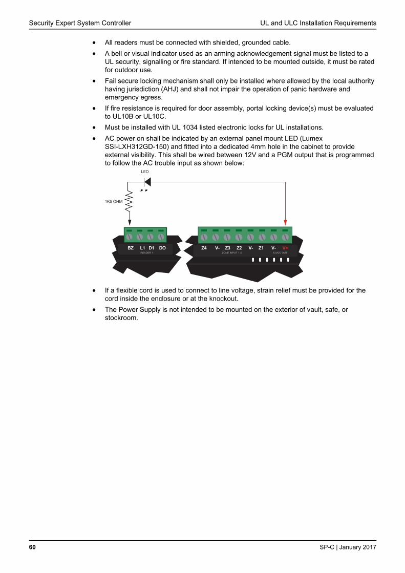
Security Expert System Controller UL and ULC Installation Requirements
60 SP-C | January 2017
All readers must be connected with shielded, grounded cable.
A bell or visual indicator used as an arming acknowledgement signal must be listed to a UL security, signalling or fire standard. If intended to be mounted outside, it must be rated for outdoor use.
Fail secure locking mechanism shall only be installed where allowed by the local authority having jurisdiction (AHJ) and shall not impair the operation of panic hardware and emergency egress.
If fire resistance is required for door assembly, portal locking device(s) must be evaluated to UL10B or UL10C.
Must be installed with UL 1034 listed electronic locks for UL installations.
AC power on shall be indicated by an external panel mount LED (Lumex SSI-LXH312GD-150) and fitted into a dedicated 4mm hole in the cabinet to provide external visibility. This shall be wired between 12V and a PGM output that is programmed to follow the AC trouble input as shown below:
BZ L1 D1 DO
LED
V+V-Z4 V- Z3 Z2 V- Z1
1K5 OHM
READER 1 ZONE INPUT 1-4 12VDC OUT
If a flexible cord is used to connect to line voltage, strain relief must be provided for the cord inside the enclosure or at the knockout.
The Power Supply is not intended to be mounted on the exterior of vault, safe, or stockroom.

FCC Compliance Statements Security Expert System Controller
SP-C | January 2017 61
FCC PART 15, WARNINGS: INFORMATION TO USER
This equipment has been tested and found to comply with the limits for a Class A digital
device, pursuant to Part 15 of the FCC Rules. These limits are designed to provide
reasonable protection against harmful interference in a residential installation. This equipment
generates, uses and can radiate radio frequency energy and, if not installed and used in
accordance with the instructions, may cause harmful interference to radio communications.
However, there is no guarantee that interference will not occur in a particular installation. If
this equipment does cause harmful interference to radio or television reception, which can be
deter-mined by turning the equipment off and on, the user is encouraged to try to correct the
interference by one or more of the following measures:
Re-orient the receiving antenna.
Increase the separation between the equipment and receiver.
Connect the equipment into an outlet on a circuit different from that to which the receiver is connected.
Changes or modifications not authorised by the party responsible for compliance could void the user's authority to operate this product.
This device complies with Part 15 of the FCC rules.
Operation is subject to the following two conditions:
This device may not cause harmful interference.
This device must accept any interference received, including interference that may cause undesired operation.
NOTE: THE GRANTEE IS NOT RESPONSIBLE FOR ANY CHANGES OR MODIFICATIONS
NOT EXPRESSLY APPROVED BY THE PARTY RESPONSIBLE FOR COMPLIANCE. SUCH
MODIFICATIONS COULD VOID THE USER’S AUTHORITY TO OPERATE THE
EQUIPMENT.
IMPORTANT INFORMATION
This equipment complies with Part 68 of the FCC Rules and the requirements adopted by the
ACTA. Inside the cover of this equipment is a label that contains, among other information, a
product identifier in the format US: AAAEQ##TXXXX. If requested, this number must be
provided to the telephone company.
FCC REGISTRATION NUMBER: US: 48DMM00BPRTCTRLDI
RINGER EQUIVALENCE NUMBER: 0.0
USOC Jack: RJ-31X
Telephone Connection Requirements
A plug and jack used to connect this equipment to the premises wiring and telephone network
must comply with the applicable FCC Part 68 rules and requirements adopted by the ACTA. A
compliant telephone cord modular plug is provided with this product. It is designed to be
connected to a compatible modular jack that is also compliant. See this document for details.
Ringer Equivalence Number (REN)
The REN is used to determine the number of devices that may be connected to a telephone
line. Excessive RENs on a telephone line may result in the devices not ringing in response to
an incoming call. In most but not all areas, the sum of RENs should not exceed five (5.0). To
be certain of the number of devices that may be connected to a line, as determined by the
total RENs, contact the local telephone company.
FCC Compliance Statements

Security Expert System Controller FCC Compliance Statements
62 SP-C | January 2017
For products approved after July 23, 2001, the REN for this product is part of the product
identifier that has the format US: AAAEQ##TXXXX. The digits represented by ## are the REN
without a decimal point (e.g., 03 is a REN of 0.3). For earlier products, the REN is separately
shown on the label.
Incidence of Harm
If this equipment (SP-C System Controller) causes harm to the telephone network, the
telephone company will notify you in advance that temporary discontinuance of service may
be required. But if advance notice isn't practical, the telephone company will notify the
customer as soon as possible. Also, you will be advised of your right to file a complaint with
the FCC if you believe it is necessary.
Changes in Telephone Company Equipment or Facilities
The telephone company may make changes in its facilities, equipment, operations or
procedures that could affect the operation of the equipment. If this happens the telephone
company will provide advance notice in order for you to make necessary modifications to
maintain uninterrupted service.
Equipment Maintenance Facility
If trouble is experienced with this equipment (SP-C System Controller), for repair or warranty
information, please contact Integrated Control Technology c/o 150 W 9th Ave, Denver, CO
80204. If the equipment is causing harm to the telephone network, the telephone company
may request that you disconnect the equipment until the problem is resolved. This equipment
is of a type that is not intended to be repaired by the end user.
Additional Information
Connection to party line service is subject to state tariffs. Contact the state public utility
commission, public service commission or corporation commission for information. Alarm
dialing equipment must be able to seize the telephone line and place a call in an emergency
situation. It must be able to do this even if other equipment (telephone, answering system,
computer modem, etc.) already has the telephone line in use. To do so, alarm dialing
equipment must be connected to a properly installed RJ-31X jack that is electrically in series
with and ahead of all other equipment attached to the same telephone line. Proper installation
is depicted in the figure below. If you have any questions concerning these instructions, you
should consult your telephone company or a qualified installer about installing the RJ-31X jack
and alarm dialing equipment for you.
Telephone
Computer
Telephone
Telephone
Fax Machine
Alarm DialingEquipment
RJ-31XJack
UnusedRJ-11 Jack
TelephoneLine
NetworkService
Provider'sFacilities
Customer Premises Equipment and Wiring
UnusedRJ-11 Jack
NetworkDemarcation
PointAnswering
System

Industry Canada Statement Security Expert System Controller
SP-C | January 2017 63
This class A digital apparatus complies with Canadian ICES-003.
Cet appareil numérique de la classe A est conforme à la norme NMB-003 du Canada.
This product meets the applicable Industry Canada technical specifications. The Ringer
Equivalence Number (REN) for this terminal equipment is 0.0. The Ringer Equivalence
Number is an indication of the maximum number of devices allowed to be connected to a
telephone interface. The termination on an interface may consist of any combination of
devices subject only to the requirement that the sum of the RENs of all the devices does not
exceed five.
L'indice d'équivalence de la sonnerie (IES) du présent matériel est de 0.0. Le présent materiel
est conforme aux spécifications techniques applicables d’Industrie Canada. L’indice
d’équivalence de la sonnerie (IES) sert à indiquer le nombre maximal de terminaux qui
peuvent être raccordés à une interface téléphonique. La terminaison d’une interface peut
consister en une combinaison quelconque de dispositifs, à la seule condition que la somme
d’indices d’équivalence de la sonnerie de tous les dispositifs n’excède pas 5.
SP-C REGISTRATION NUMBER IC: 10012A-SPC
SP-C NUMÉRO D'ENREGISTREMENT IC: 10012A-SPC
Industry Canada Statement

Schneider Electric
www.schneider-electric.com
© 2016 Schneider Electric. All rights reserved.
January 2017