security enhanced multi-domain network … · the se-mdnm module supports the network connection of...
TRANSCRIPT

AFRL-IF-RS-TR-2005-86
Final Technical Report March 2005 SECURITY ENHANCED MULTI-DOMAIN NETWORK MANAGEMENT FOR JOINT WARRIOR INTEROPERABILITY DEMONSTRATION (JWID) Dolphin Technology, Incorporated
APPROVED FOR PUBLIC RELEASE; DISTRIBUTION UNLIMITED.
AIR FORCE RESEARCH LABORATORY INFORMATION DIRECTORATE
ROME RESEARCH SITE ROME, NEW YORK
STINFO FINAL REPORT This report has been reviewed by the Air Force Research Laboratory, Information Directorate, Public Affairs Office (IFOIPA) and is releasable to the National Technical Information Service (NTIS). At NTIS it will be releasable to the general public, including foreign nations. AFRL-IF-RS-TR-2005-86 has been reviewed and is approved for publication APPROVED: /s/
SCOTT S. SHYNE Project Engineer
FOR THE DIRECTOR: /s/
JOSEPH CAMERA, Chief Information & Intelligence Exploitation Division Information Directorate
REPORT DOCUMENTATION PAGE Form Approved
OMB No. 074-0188 Public reporting burden for this collection of information is estimated to average 1 hour per response, including the time for reviewing instructions, searching existing data sources, gathering and maintaining the data needed, and completing and reviewing this collection of information. Send comments regarding this burden estimate or any other aspect of this collection of information, including suggestions for reducing this burden to Washington Headquarters Services, Directorate for Information Operations and Reports, 1215 Jefferson Davis Highway, Suite 1204, Arlington, VA 22202-4302, and to the Office of Management and Budget, Paperwork Reduction Project (0704-0188), Washington, DC 20503 1. AGENCY USE ONLY (Leave blank)
2. REPORT DATEMARCH 2005
3. REPORT TYPE AND DATES COVERED Final Jun 03 – Dec 04
4. TITLE AND SUBTITLE SECURITY ENHANCED MULTI-DOMAIN NETWORK MANAGEMENT FOR JOINT WARRIOR INTEROPERABILITY DEMONSTRATION (JWID)
6. AUTHOR(S) James Marcinkowski and Roger Miller
5. FUNDING NUMBERS C - F30602-01-D-0167/0017 PE - 23761F PR - 2183 TA - QB WU - 17
7. PERFORMING ORGANIZATION NAME(S) AND ADDRESS(ES) Dolphin Technology, Incorporated 474 Phoenix Drive Rome New York 13441-4911
8. PERFORMING ORGANIZATION REPORT NUMBER
N/A
9. SPONSORING / MONITORING AGENCY NAME(S) AND ADDRESS(ES) Air Force Research Laboratory/IFEB 525 Brooks Road Rome New York 13441-4505
10. SPONSORING / MONITORING AGENCY REPORT NUMBER
AFRL-IF-RS-TR-2005-86
11. SUPPLEMENTARY NOTES AFRL Project Engineer: Scott S. Shyne/IFEB/(315) 330-4819/ [email protected]
12a. DISTRIBUTION / AVAILABILITY STATEMENT APPROVED FOR PUBLIC RELEASE; DISTRIBUTION UNLIMITED.
12b. DISTRIBUTION CODE
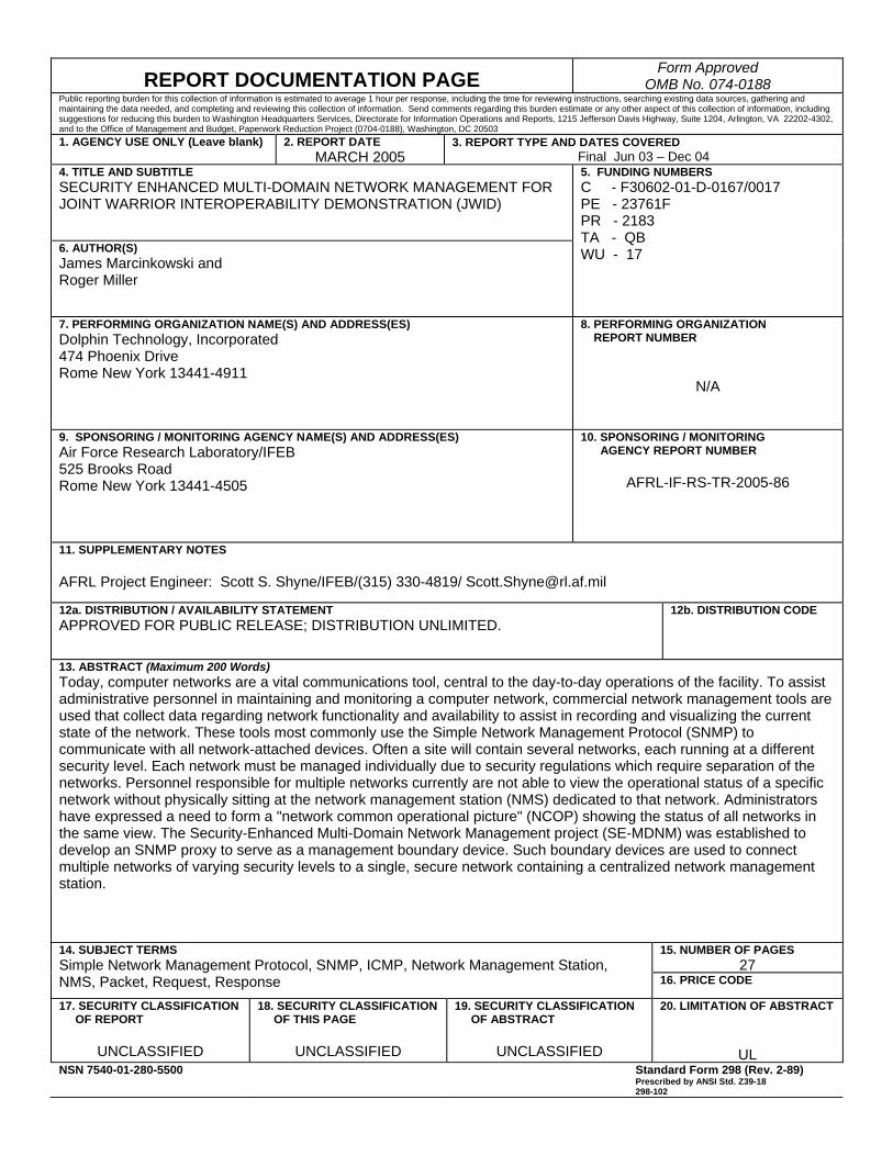
13. ABSTRACT (Maximum 200 Words)Today, computer networks are a vital communications tool, central to the day-to-day operations of the facility. To assist administrative personnel in maintaining and monitoring a computer network, commercial network management tools are used that collect data regarding network functionality and availability to assist in recording and visualizing the current state of the network. These tools most commonly use the Simple Network Management Protocol (SNMP) to communicate with all network-attached devices. Often a site will contain several networks, each running at a different security level. Each network must be managed individually due to security regulations which require separation of the networks. Personnel responsible for multiple networks currently are not able to view the operational status of a specific network without physically sitting at the network management station (NMS) dedicated to that network. Administrators have expressed a need to form a "network common operational picture" (NCOP) showing the status of all networks in the same view. The Security-Enhanced Multi-Domain Network Management project (SE-MDNM) was established to develop an SNMP proxy to serve as a management boundary device. Such boundary devices are used to connect multiple networks of varying security levels to a single, secure network containing a centralized network management station.
15. NUMBER OF PAGES27
14. SUBJECT TERMS Simple Network Management Protocol, SNMP, ICMP, Network Management Station, NMS, Packet, Request, Response 16. PRICE CODE
17. SECURITY CLASSIFICATION OF REPORT
UNCLASSIFIED
18. SECURITY CLASSIFICATION OF THIS PAGE
UNCLASSIFIED
19. SECURITY CLASSIFICATION OF ABSTRACT
UNCLASSIFIED
20. LIMITATION OF ABSTRACT
ULNSN 7540-01-280-5500 Standard Form 298 (Rev. 2-89)
Prescribed by ANSI Std. Z39-18 298-102
Table of Contents 1. Introduction........................................................................................................................... 1
2. SE-MDNM Software Architecture...................................................................................... 2 2.1 Configuration .................................................................................................................. 2 2.2 Interface Design .............................................................................................................. 3
2.2.1 The SNMP Architecture ......................................................................................... 4 2.2.2 Internal Interfaces ................................................................................................... 7
2.3 Message Sequence Overview ....................................................................................... 10 2.3.1 NMS Message Flow Details ................................................................................. 11 2.3.2 SNMP Get Request Message Flow....................................................................... 14
3. Summary.............................................................................................................................. 20 3.1 Current SE-MDNM Prototype Capabilities.................................................................. 20 3.2 Current SE-MDNM Prototype Limitations .................................................................. 20 3.3 Recommendations......................................................................................................... 21
3.3.1 SE-MDNM Thread Recommendations................................................................. 21 3.3.2 SE-MDNM Client Recommendations .................................................................. 21
i

List of Figures Figure 2-1: SE-MDNM Network Architecture.............................................................................. 3 Figure 2-2: ISSE Guard TCI Internal and External Interfaces ...................................................... 4 Figure 2-3 Spectrum Message Flow ............................................................................................ 11 Figure 2-4 ICMP Echo Request Packet Captured with Snoop .................................................... 12 Figure 2-5 Format of ICMP Packet .............................................................................................. 12 Figure 2-6 Message Format of Message Sent to SNMP Trusted Process .................................... 14 Figure 2-7 SNMP Get Request Packet Captured with Snoop...................................................... 16 Figure 2-8 Message Queue Message Format............................................................................... 17 Figure 2-9 SNMP Trap Captured with Snoop ............................................................................. 18
List of Tables Table 2-1 SMNP Message Type Processing................................................................................ 15
ii

1. Introduction This report, entitled Security Enhanced Multi-Domain Network Management (SE-MDNM) Final Technical Report, documents the software architecture, summary, and recommendations resulting from the SE-MDNM effort for the Secure Trusted Automated Routing (STAR) Guard Server v1.0 software components as they will be used within the STAR Guard architecture. This report fulfills Contract Data Requirements List (CDRL) Item A012 under Contract No. F30602-01-D-0167/0017, Subcontract No DB21II-SC-02-005, DO9026-5000.
1

2. SE-MDNM Software Architecture At military sites today, computer networks are a vital communications tool, central to the day-to-day operations of the facility. To assist administrative personnel in maintaining and monitoring a computer network, commercial network management tools are used that collect data regarding network functionality and availability to assist in recording and visualizing the current state of the network. These tools most commonly use the Simple Network Management Protocol (SNMP) to communicate with all network-attached devices.
Often a site will contain several networks, each running at a different security level. Each network must be managed individually due to security regulations which require separation of the networks. Personnel responsible for multiple networks currently are not able to view the operational status of a specific network without physically sitting at the network management station (NMS) dedicated to that network. Administrators have expressed a need to form a “network common operational picture” (NCOP) showing the status of all networks in the same view.
The Security-Enhanced Multi-Domain Network Management project (SE-MDNM) was established to develop an SNMP proxy to serve as a management boundary device. Such boundary devices are used to connect multiple networks of varying security levels to a single, secure network containing a centralized network management station.
2.1 Configuration The SE-MDNM module supports the network connection of a single Network Management Station (NMS) to the high side of the Information Support Server Environment (ISSE) Guard utilizing an Out-of-Band (OOB) connection detailed in Figure 2-1. This configuration requires the NMS to have a dedicated network interface connected exclusively to the high side interface of the ISSE Guard. Other network interfaces may be installed on the NMS for connection to one or more high side networks operating at the same security level. Routing on the NMS must be configured to provide all network traffic destined for the low side networks to be routed through the OOB connection to the ISSE Guard (Note: there cannot be a router or switch between NMS and ISSE Guard). One or more low side networks may be connected to the low side of the ISSE Guard, limited only by the number of network interface cards the ISSE Guard hardware platform can support. The high and low side SE-MDNM client processes must be located on the ISSE Guard platform to provide enhanced security to guarantee the integrity of the Internet Control Message Protocol (ICMP) and Simple Network Management Protocol (SNMP) packets being passed through the ISSE Guard.
2
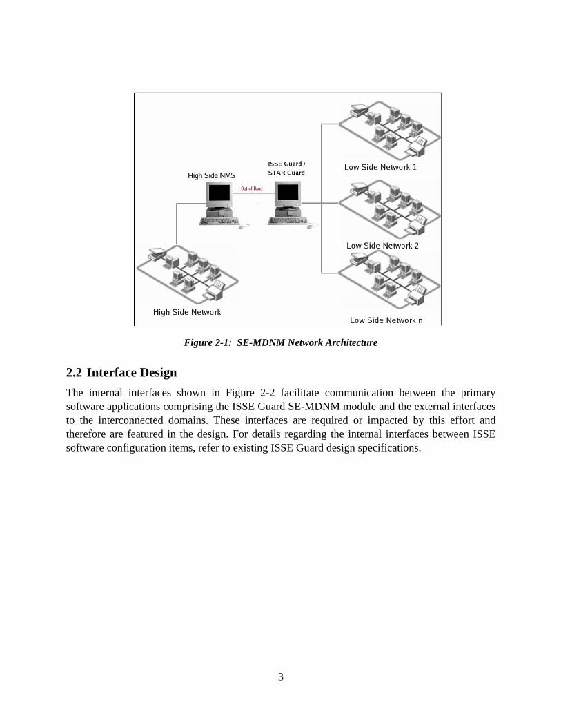
Figure 2-1: SE-MDNM Network Architecture
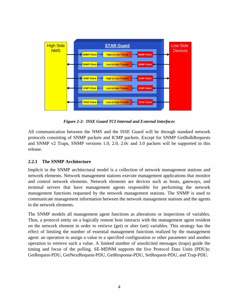
2.2 Interface Design The internal interfaces shown in Figure 2-2 facilitate communication between the primary software applications comprising the ISSE Guard SE-MDNM module and the external interfaces to the interconnected domains. These interfaces are required or impacted by this effort and therefore are featured in the design. For details regarding the internal interfaces between ISSE software configuration items, refer to existing ISSE Guard design specifications.
3
STAR Guard
SNMP Client High to Low Thread SNMP Client
SNMP Client Low to High Trusted SNMP Client
ICMP Client High to Low Trusted ICMP Client
ICMP Client Low to High Trusted ICMP Client
TRAP Client Low to High Trusted TRAP Client
Low Side Devices
High SideNMS
STAR Guard
SNMP Client High to Low Thread SNMP Client
SNMP Client Low to High Trusted SNMP Client
ICMP Client High to Low Trusted ICMP Client
ICMP Client Low to High Trusted ICMP Client
TRAP Client Low to High Trusted TRAP Client
Low Side Devices
High SideNMS
Figure 2-2: ISSE Guard TCI Internal and External Interfaces
All communication between the NMS and the ISSE Guard will be through standard network protocols consisting of SNMP packets and ICMP packets. Except for SNMP GetBulkRequests and SNMP v2 Traps, SNMP versions 1.0, 2.0, 2.0c and 3.0 packets will be supported in this release.
2.2.1 The SNMP Architecture
Implicit in the SNMP architectural model is a collection of network management stations and network elements. Network management stations execute management applications that monitor and control network elements. Network elements are devices such as hosts, gateways, and terminal servers that have management agents responsible for performing the network management functions requested by the network management stations. The SNMP is used to communicate management information between the network management stations and the agents in the network elements.
The SNMP models all management agent functions as alterations or inspections of variables. Thus, a protocol entity on a logically remote host interacts with the management agent resident on the network element in order to retrieve (get) or alter (set) variables. This strategy has the effect of limiting the number of essential management functions realized by the management agent: an operation to assign a value to a specified configuration or other parameter and another operation to retrieve such a value. A limited number of unsolicited messages (traps) guide the timing and focus of the polling. SE-MDNM supports the five Protocol Data Units (PDU)s: GetRequest-PDU, GetNextRequest-PDU, GetResponse-PDU, SetRequest-PDU, and Trap-PDU.
4
2.2.1.1 SNMP Message Format
Communication among protocol entities is accomplished by the exchange of messages, each of which is entirely and independently represented within a single User Datagram Protocol (UDP) datagram using the basic encoding rules of Abstract Syntax Notation One (ASN.1). All messages consist of a version identifier, a community name for non SNMP v3 messages, and a PDU. In the case of SNMP v3 messages, a message may contain additional security measures including message authentication via MD5 or SHA1 hashing and possibly PDU encoding via Cipher Block Chaining-Data Encryption Standard (CBC-DES) encryption. A protocol entity receives messages at UDP port 161 on the host with which it is associated for all messages, except for those that report traps (i.e., all messages except those which contain the Trap-PDU). Messages which report traps should be received on UDP port 162 for further processing. An implementation of this protocol need not accept messages whose length exceeds 484 octets.
In the case of SNMP v3.0 messages, there are three security levels that SNMP v3.0 PDU messages may travel while going from the host NMS through the Guard and then to the target device and back again. The following provides details regarding the three SNMP v3.0 security levels and how the Guard handles the various SNMP v3.0 security levels it can encounter while processing a SNMP v3.0 message.
The NMS sends out SNMP v3.0 messages that, depending on the configured security level, may have one of three levels of security:
1. No Authentication and No Encryption (i.e. no security)
2. MD5 or SHA1 Authentication and No Encryption (moderately secure)
3. MD5 or SHA1 Authentication and CBC-DES Encryption (most secure)
The security level of the message and the user name of the sender are both embedded in the message header. When the message arrives at the Guard, it is parsed. After the security level and username have been parsed out of the message, it accesses the snmpv3users fact base file for data specific to the parsed out username. Based on the user name that was parsed out of the SNMP v3.0 message, the appropriate password is extracted from the snmpv3users file. The password received from the fact base file should allow authentication and decryption of the message. If the extracted password does not allow validation, the authentication and/or encryption of the message is rejected.
As mentioned above, to facilitate the three levels of SNMP v3.0 security, the Guard keeps a file on the trusted platform called snmpv3users.fb. The trusted thread has access to this file and reads it in upon start up. The file contains the usernames and associated passwords used for facilitating both encryption and authentication of snmpv3 messages. The file itself is secured by having a SHA 1 checksum applied to it.
5
2.2.1.1.1 SNMP Managed Object Definition
The definition of managed objects can be broken down into three attributes:
1. Name: The name, or Object Identifier (OID), uniquely defines a managed object; SE-MDNM only supports the numeric form of OID's
2. Type and Syntax: A managed objects datatype is defined using a subset of ASN.1. ASN.1 is a way of specifying how data is represented and transmitted between managers and agents, within the context of SNMP
3. Encoding: A single instance of a managed object is encoded into a string of octets using the Basic Encoding Rules (BER). BER defines how the objects are encoded and decoded so they can be transmitted over a transport medium such as Ethernet
2.2.1.2 SNMP Data Types
This section describes the SNMP data types supported by the SE-MDNM module.
Integer: A 32-bit number often used to specify enumerated types within the context of a single managed object. For example, the operational status of a router interface can be up, down, or testing. With enumerated types, 1 would represent up, 2 down and 3 testing. According to RFC 1155, the value zero (0) must not be used as an enumerated type.
Octet String: A string of zero or more octets (more commonly known as bytes) generally used to represent text strings; occasionally used to represent physical addresses.
Counter: A 32-bit number with minimum value 0 and maximum value of 4,294,967,295. When the maximum value is reached, it wraps back to zero and starts over. It is primarily used to track information such as the number of octets sent and received on an interface or the number of errors and discards seen on an interface. A Counter is monotonically increasing, in that its values should never decrease during normal operation. When an agent is rebooted, all Counter values should be set to zero. Deltas are used to determine if anything useful can be said for successive queries of Counter values. A delta is computed by querying a Counter at least twice in a row and taking the difference between the query results over some time interval.
Object Identifier: Dotted decimal string that represents a managed object within the object tree.
Sequence: Defines lists that contain zero or other ASN.1 data types.
6
Sequence of: Defines a managed object that is made up of a SEQUENCE of ASN.1 types.
IpAddress: Represents a 32-bit IPv4 address.
NetworkAddress: Same as the IPAddress type, but can represent different network address types.
Gauge: 32-bit number with minimum value 0 and a maximum value of 4,294,967,295. Unlike a Counter, a Gauge can increase and decrease at will, but it can never exceed its maximum value.
TimeTicks: 32-bit number with minimum value 0 and a maximum value of 4,294,967,295. TimeTicks measure time in hundredths of a second.
Opaque: Allows any other ASN.1 encoding to be stuffed into an OCTET STRING.
Integer32: Same as an INTEGER.
Counter32: Same as a Counter.
Gauge32: Same as a Gauge.
Unsigned32: Represents decimal values in the range of 0 to 4,294,967,295 inclusive.
Counter64: Similar to Counter32, but its maximum value is 18,446,744,073,709,551,615.
BITS: An enumeration of nonnegative named bits.
2.2.2 Internal Interfaces
This section describes the internal interfaces, or ‘STAR threads’, required for passing SNMP and ICMP packets through the STAR Guard in both the high-to-low and low-to-high directions.
2.2.2.1 ICMP High-to-Low: High Side Client
The ICMP high-to-low, high side client uses libpcap version 0.8.1 for capturing all network packets from the OOB connection to the NMS. For communication with the ICMP high-to-low, high side client, shared memory is utilized for saving the following information contained in an ICMP Echo Request Packet:
7
• Source IP address
• Destination IP address
• Key identifier for this packet
• Payload from this packet
The ICMP high-to-low, high side client uses the following STAR Application Programmer’s Interface (API) functions to communicate with the ICMP high-to-low trusted process:
• ConnectStar()
• WriteStar()
• CloseStar()
2.2.2.2 ICMP High-to-Low: Low Side Client
The ICMP high-to-low, low side client uses the following STAR API functions to communicate with the ICMP high-to-low trusted process:
• ConnectStar()
• ReadStar()
• CloseStar()
The ICMP high-to-low, low side client uses libnet version 1.1.1 functions to transmit the ICMP Echo Request to the appropriate low side node.
2.2.2.3 ICMP Low-to-High: High Side Client
The ICMP low-to-high, high side client uses libnet version 1.1.1 functions to create the response packet and return it to the high side NMS. The following STAR API functions are used to communicate with the low-to-high trusted process:
• ConnectStar()
• ReadStar()
• CloseStar()
2.2.2.4 ICMP Low-to-High: Low Side Client
The ICMP low-to-high, low side clients use libpcap version 0.8.1 for capturing all network ICMP packets from the low side network interface for which they are configured to listen.
8

The ICMP low-to-high, low side clients use the following STAR API functions to communicate with the ICMP low-to-high trusted process:
• ConnectStar()
• WriteStar()
• CloseStar()
2.2.2.5 SNMP High-to-Low: High Side Client
The SNMP high-to-low, high side client uses libpcap version 0.8.1 for capturing all network packets from the OOB connection to the NMS. For communication with the SNMP low-to-high, high side client, shared memory is utilized for saving the following information contained in an ICMP Echo Request Packet:
• Source IP address
• Destination IP address
• Key identifier for this packet
• Request id for SNMP Request The SNMP high-to-low, high side client uses the following STAR API functions to communicate with the SNMP high-to-low trusted process:
• ConnectStar()
• WriteStar()
• CloseStar()
2.2.2.6 SNMP High-to-Low: Low Side Client
The SNMP high-to-low, low side client uses libnet version 1.1.1 functions to transmit the SNMP Requests to the appropriate low side node.
The SNMP high-to-low, low side client uses the following STAR API functions to communicate with the SNMP high-to-low trusted process:
• ConnectStar()
• ReadStar()
• CloseStar()
9

The SNMP high-to-low, low side client uses a Message Queue to transmit SNMP responses to the SNMP low-to-high, low side client. The SNMP response message from the Get Request to the low side node is parsed into a snmppkt data structure. The snmpH2LlowClient places the data contained in the data structure onto the message queue with a message type of 2. The format of the data contained in the message queue is described in Figure 2-3.
2.2.2.7 SNMP Low-to-High: High Side Client
The SNMP high-to-low high side client uses the following STAR API functions to communicate with the SNMP high-to-low process:
• ConnectStar()
• ReadStar()
• CloseStar()
2.2.2.8 SNMP Low-to-High: Low Side Client
The SNMP low-to-high, low side client uses a Message Queue to receive SNMP responses from the snmpH2LlowClient. The snmpL2HlowClient waits for any messages with the message type of 2 and pops them off the queue and delivers them to the SNMP low-to-high trusted process via STAR API calls. See
Figure 2-3 for the format of the data contained in the message queue.
The SNMP low-to-high, low side client uses the following STAR API functions to communicate with the SNMP high-to-low Thread:
• ConnectStar()
• WriteStar()
• CloseStar()
2.3 Message Sequence Overview Figure 2-3 details the message flow generated by a Spectrum NMS managing a node on a low side network. Spectrum will first attempt to ping the low side device (Step 1). Only if it receives a successful reply will Spectrum proceed to Step 2 and send the SNMP Request to that device.
10

NMS HighNMS High High Client(s)High Client(s) Low Client(s)Low Client(s)High to Low ThreadHigh to Low Thread Low DevicesLow DevicesHigh to Low ThreadHigh to Low Thread
Ping Request
WriteSTAR(request)ReadSTAR( ping )ReadSTAR( ping )
Forward Ping
Ping ReplyWriteSTAR(reply)
ReadSTAR( reply )Proxy Ping Reply
SNMP Request
22
WriteSTAR(request)
Save Transaction
Filter MessageFilter Message
ReadSTAR( snmp )
Clean SNMP
SNMP Response
WriteSTAR(response)
ReadSTAR(response)
Proxy SNMP Response
11
Figure 2-3 Spectrum Message Flow
2.3.1 NMS Message Flow Details
The following sections detail the message flows associated with each message created by the NMS to do a SNMP Get Request of a given node on a low side network. These descriptions are organized by the component of the architecture which performs each processing step.
2.3.1.1 ICMP Echo Requests Message Flow
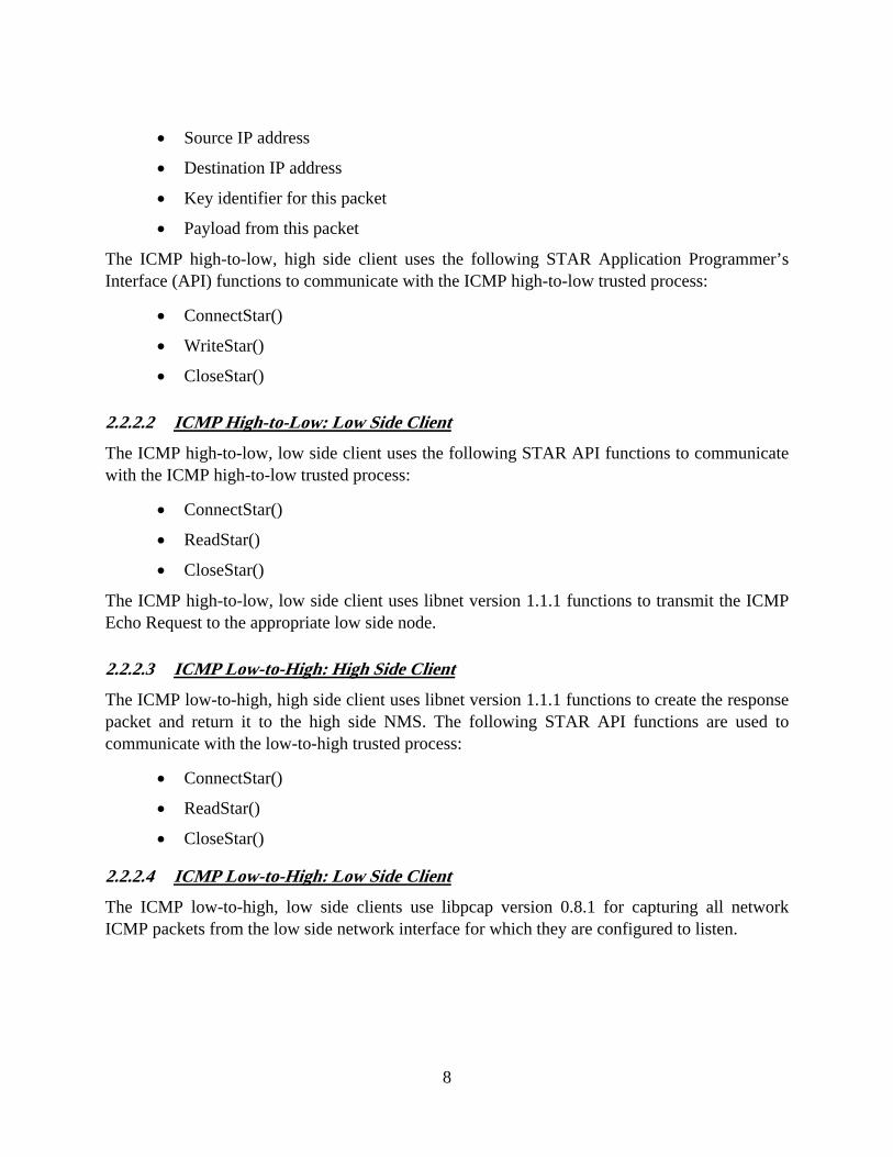
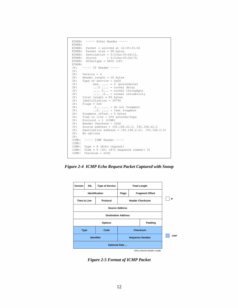
The following describes the message flow within the system to processes ICMP Echo Request messages. This message, also known as a ping, is used to verify if a node is reachable. Figure 2-4 depicts an actual ICMP Echo Request packet captured using the Snoop utility, while Figure 2-5 graphically depicts the ICMP packet composition.
11
ETHER: ----- Ether Header ----- ETHER: ETHER: Packet 1 arrived at 12:35:33.52 ETHER: Packet size = 98 bytes ETHER: Destination = 0:3:ba:35:2d:11, ETHER: Source = 0:3:ba:35:2d:79, ETHER: Ethertype = 0800 (IP) ETHER: IP: ----- IP Header ----- IP: IP: Version = 4 IP: Header length = 20 bytes IP: Type of service = 0x00 IP: xxx. .... = 0 (precedence) IP: ...0 .... = normal delay IP: .... 0... = normal throughput IP: .... .0.. = normal reliability IP: Total length = 84 bytes IP: Identification = 39790 IP: Flags = 0x4 IP: .1.. .... = do not fragment IP: ..0. .... = last fragment IP: Fragment offset = 0 bytes IP: Time to live = 255 seconds/hops IP: Protocol = 1 (ICMP) IP: Header checksum = 32d2 IP: Source address = 192.168.42.2, 192.168.42.2 IP: Destination address = 192.168.2.21, 192.168.2.21 IP: No options IP: ICMP: ----- ICMP Header ----- ICMP: ICMP: Type = 8 (Echo request) ICMP: Code = 0 (ID: 1872 Sequence number: 0) ICMP: Checksum = e542
Figure 2-4 ICMP Echo Request Packet Captured with Snoop
*(IHL) Internet Header Length
Version IHL Type of Service Total Length
Identification Flags
Header ChecksumProtocolTime to Live
Source Address
Destination Address
Options
Type Code Checksum
Sequence NumberIdentifier
Padding
Optional Data …
Fragment Offset
Version IHL Type of Service Total Length
Identification Flags
Header ChecksumProtocolTime to Live
Source Address
Destination Address
Options
Type Code Checksum
Sequence NumberIdentifier
Padding
Optional Data …
Fragment Offset
IP
ICMP
Figure 2-5 Format of ICMP Packet
12
NMS: The NMS will issue an ICMP Echo Request, which is received by the ICMP high-to-low: high side client.
ICMP High-to-Low: High Side Client (icmpH2LhighClient): The icmpH2LhighClient will capture this Echo Request and add entry in the transaction table. Each transaction is unique and contains the original payload of the ICMP packet. The client then creates and sends a message to the STAR Guard containing the destination address and the original ICMP sequence number. This sequence number will be used on the return trip to verify the transaction.
ICMP High-to-Low: Trusted Process (trusted_icmp): The ICMP trusted process then forwards the Internet Protocol (IP) address and sequence number to the low-side client. Because the original ICMP packet is not actually sent through the STAR Guard, no filtering is necessary. The original payload is stored only on the high side, in the form of an outgoing transaction. This information will be used later to build a proxy Ping response.
ICMP High-to-Low: Low Side Client (icmpH2LlowClient): The icmpH2LlowClient is continually waiting for messages (Ping Requests) to arrive from the STAR Guard. When the message arrives, the icmpH2LlowClient uses the destination address and sequence number (transaction key) from the message to build a new Ping Request. The Libnet packet library is used to inject the newly created packet onto the wire. Any responses from a Ping Request will be handled by the low side client of the return thread.
2.3.1.2 ICMP Echo Responses Message Flow
The following describes the messages created and handled for transmitting the echo responses from the low side nodes back to the high side NMS.
ICMP Low-to-High: Low Side Client (icmpL2HlowClient): For every network interface on the low side of the STAR Guard, an icmpL2HlowClient is waiting to capture Ping responses. Once an ICMP echo response is captured, the low side client passes the ICMP portion of the packet to the trusted process via a WriteSTAR() call . (See Figure 2-6)
ICMP Low-to-High: Trusted Process (trusted_icmp): As with the high-to-low trusted process, the actual packet being forwarded from low-to-high will only be used to build a similar Ping Response packet. Therefore, no filtering is required in the trusted process and the ICMP portion of the response packet is passed though.
13

ICMP Low-to-High: High Side Client (icmpL2HhighClient): The icmpL2HhighClient is also continually waiting for messages (Ping Responses) to arrive from the STAR Guard. A Ping Response received from the STAR Guard should contain a sequence ID that matches one of the Ping Requests currently stored in the transaction map. If a transaction matching that ID cannot be found, the packet is dropped and audited. If the message is a valid response to a previous request, a new ICMP packet is created and returned to the high side NMS. The “new” response packet is built using the original Ping Request data. Again, the Libnet library is used to inject the packet onto the wire.
2.3.2 SNMP Get Request Message Flow
After the echo response has been received by the NMS, it will begin issuing the SNMP Get/Set Requests. See Figure 2-6 for a sample SNMP Get Request packet.
Source Port
Source Address
Unused
Destination Address
Source Address Family
Destination PortDestination Address Family
Unused
Packet Length
SNMP Data…
Source Port
Source Address
Unused
Destination Address
Source Address Family
Destination PortDestination Address Family
Unused
Packet Length
SNMP Data…
Figure 2-6 Message Format of Message Sent to SNMP Trusted Process
14

SNMP High-to-Low: High Side Client (snmpH2LhighClient): The snmpH2LhighClient uses libpcap functions to capture the SNMP Get/Set Request and adds an entry into shared memory containing the source and destination addresses, a unique key to retrieve this data, and the request ID from the request. A message is created (Figure 2-6) and passed to the SNMP High-to-Low trusted process with a WriteSTAR() call.
SNMP High-to-Low: Trusted Process (trusted_snmp): The trusted process parses the data found in the high side shared memory segment into a snmppkt structure. The ASN.1 data payload located in the snmppkt structure is then passed out into a linked list of ASN.1 objects. The direction is checked (either high-to-low or low-to-high) and the type of SNMP packet is validated to determine if processing should be allowed for the direction the packet is going in. Table 2-1 shows the allowable and disallowable types for each direction.
Table 2-1 SMNP Message Type Processing
Snmp Type High-to-Low Low-to-High
Get Request Allowed Disallowed
Get Next Request Allowed Disallowed
Get Bulk Request Disallowed Disallowed
Get Response Disallowed Allowed
Set Request Allowed Disallowed
Trap Disallowed Allowed
Validation of the packets can fail if any of the following conditions exist:
• The SNMP type is disallowed in the direction the packet is going,
• The packet is of type Get Request or Get Next Request and values are not null for the OIDs contained in the packet,
• In the case of SNMP v3.0 message, if the message can not be authenticated or decrypted
If validation of the packet type fails, the packet is put into an error queue, the event is audited and all processing of the packet is terminated. After the packet data has been validated, the trusted process then sends the Get Request to the SNMP high-to-low: low side client (snmpH2LlowClient).
15
ETHER: ----- Ether Header ----- ETHER: ETHER: Packet 13 arrived at 12:35:53.34 ETHER: Packet size = 82 bytes ETHER: Destination = 0:3:ba:35:2d:11, ETHER: Source = 0:3:ba:35:2d:79, ETHER: Ethertype = 0800 (IP) ETHER: IP: ----- IP Header ----- IP: IP: Version = 4 IP: Header length = 20 bytes IP: Type of service = 0x00 IP: xxx. .... = 0 (precedence) IP: ...0 .... = normal delay IP: .... 0... = normal throughput IP: .... .0.. = normal reliability IP: Total length = 68 bytes IP: Identification = 35321 IP: Flags = 0x4 IP: .1.. .... = do not fragment IP: ..0. .... = last fragment IP: Fragment offset = 0 bytes IP: Time to live = 255 seconds/hops IP: Protocol = 17 (UDP) IP: Header checksum = 4446 IP: Source address = 192.168.42.2, 192.168.42.2 IP: Destination address = 192.168.2.22, 192.168.2.22 IP: No options IP: UDP: ----- UDP Header ----- UDP: UDP: Source port = 32878 UDP: Destination port = 161 UDP: Length = 48 UDP: Checksum = 9BDC
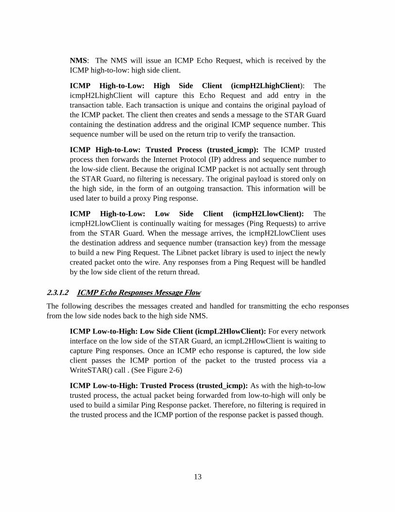
Figure 2-7 SNMP Get Request Packet Captured with Snoop
SNMP High-to-Low: Low Side Client (snmpH2LlowClient): The snmpH2LlowClient receives the Get Request by calling ReadSTAR() once it is notified that the socket connection to the thread has data waiting to be read. Using libnet functions, the snmpH2LlowClient sends the Get Request to the low side node.
2.3.2.1 SNMP Get Responses Message Flow
The following describes the messages created and handled for transmitting the SNMP Get Responses from the low side nodes back to the high side NMS.
16

SNMP High-to-Low: Low Side Client (snmpH2LlowClient): After the snmpH2LlowClient sends a Get Request off to a low side node it waits for a get response from the low side node. Upon receiving a response the snmpH2LlowClient places an entry in the message queue for the SNMP Low-to-High Low Client (snmpL2HlowClient). Figure 2-8 describes the format of the data contained on the message queue for delivery to the snmpL2HlowClient.
Source Port
Source Address
Destination Address
Source Address Family
Destination PortDestination Address Family
Unused
Packet Length
SNMP Data…
Message Type
Source Port
Source Address
Destination Address
Source Address Family
Destination PortDestination Address Family
Unused
Packet Length
SNMP Data…
Message Type
Figure 2-8 Message Queue Message Format
SNMP Low-to-High: Low Side Client (snmpL2HlowClient): The snmpL2HlowClient retrieves the get response message from the message queue and creates a message. It then parses the get response to the SNMP low-to-high trusted process by calling WriteSTAR(). (See Figure 2-8 for the format of a message).
SNMP Low-to-High: Trusted Process: The trusted process parses the message received from the snmpL2HlowClient into a snmppkt structure. The asn1 data payload located in the snmppkt structure is then passed out into a linked list of asn1 objects. The direction is checked (either high-to-low or low-to-high) and the type of SNMP packet is validated for allowable processing for the direction the packet is going in. If validation of the packet type fails, the packet is put into an error queue, the event is audited, and all processing of the packet is terminated. If validation passes, and the packet is going from low-to-high, then the trusted process sends the Get Response to the SNMP low-to-high, high side client (snmpL2HhighClient).
17

SNMP Low-to-High: High Side Client: The snmpL2HhighClient parses out the Get Response from the message received from the trusted process. The original port number is retrieved from the inter-thread inter-process communication (ipc) shared memory. The destination port number is then set to the original port number. The client creates and sends the Get Response packet to the NMS using libnet functions to complete the SNMP Get Request/Get Response process.
2.3.2.2 SNMP Traps Message Flow
The following describes the messages created and handled for transmitting the SNMP traps from the low side nodes to the high side NMS:
Low Side Nodes: The low side nodes are configured to send any SNMP Traps to the appropriate low side network interface of the ISSE Guard (see Figure 2-9 for a trap example).
ETHER: Packet 1 arrived at 9:38:17.57 ETHER: Packet size = 125 bytes ETHER: Destination = 0:3:ba:8:57:67, ETHER: Source = 0:90:fb:8:9b:ae, ETHER: Ethertype = 0800 (IP) ETHER: IP: ----- IP Header ----- IP: IP: Version = 4 IP: Header length = 20 bytes IP: Type of service = 0x00 IP: xxx. .... = 0 (precedence) IP: ...0 .... = normal delay IP: .... 0... = normal throughput IP: .... .0.. = normal reliability IP: Total length = 111 bytes IP: Identification = 0 IP: Flags = 0x4 IP: .1.. .... = do not fragment IP: ..0. .... = last fragment IP: Fragment offset = 0 bytes IP: Time to live = 63 seconds/hops IP: Protocol = 17 (UDP) IP: Header checksum = 7870 IP: Source address = 192.168.64.117, roger IP: Destination address = 192.168.1.72, MDNM-HI.dolphtech.com IP: No options IP: UDP: ----- UDP Header ----- UDP: UDP: Source port = 32788 UDP: Destination port = 162 UDP: Length = 91 UDP: Checksum = C615
Figure 2-9 SNMP Trap Captured with Snoop
18

TRAP Low-to-High: Low Side Client: The Trap low-to-high, low client (trapL2HlowClient) binds to the UDP 162 port on the ISSE Guard’s low side network interface and waits for trap messages.
TRAP Trusted Process (trusted_snmp): The trusted process parses the message received from the trapL2HlowClient into a snmppkt structure. The asn1 data payload located in the snmppkt structure is then parsed out into a linked list of asn1 objects. If validation of the packet type fails, the packet is put into an error queue, the event is audited, and all processing of the packet is terminated. If validation passes, the trusted process then sends the trap to the TRAP low-to-high, high side client (trapL2HhighClient).
TRAP Low-to-High: High Side Client: The trapL2HhighClient parses out the trap from the message received from the trusted process, creates a trap packet, and sends the trap packet to the NMS using libnet functions to complete the SNMP trap process.
NMS: Upon reception of a trap, the NMS will initiate the appropriate SNMP Get/Set Requests to the affected low side node.
19

3. Summary The following sections describe the current capabilities and limitations of the current SE-MDNM design along with the recommendations for further enhancement of the capabilities provided by SE-MDNM.
3.1 Current SE-MDNM Prototype Capabilities Each component of the SE-MDNM system has been prototyped and is functional within a certain demonstrable scope. These components include the SE-MDNM STAR threads and the SE-MDNM clients. The SE-MDNM STAR module can support any generic SNMP v1.2 or v3 traffic from low-to-high and high-to-low. SNMP traps are also supported only in the low-to-high direction. ICMP support is provided for Echo Requests and Echo Responses. This not only allows for monitoring, but also management of low side nodes from a single high side network management station. Any network management software application which utilizes only standard SNMP requests can be supported as the high side network management station. Currently the SE-MDNM capability has been tested against Aprisma Spectrum, Hewlett Packard OpenView and open source OpenNMS network management software using both MIMIC SNMP node emulators to create virtual nodes and net-snmp on real nodes.
3.2 Current SE-MDNM Prototype Limitations The current limitations of the SE-MDNM module are current SE-MDNM clients must be located on the same platform that the STAR Guard is located. This may or may not be a limitation, depending on the level of security required for the client software. It was determined that the clients would be more secure being located on a Trusted Solaris™ platform rather than located on external platforms from the STAR Guard.
The current schema provides for any well formatted and allowed type of SNMP packet to be transferred across the security boundary. Currently there is no capability to restrict the SNMP traffic to a specific subset of OID’s to control the traffic allowed to pass across the security boundary. SNMP packets are checked for compliance to the data types allowed in a well formed SNMP packet, but limitations are not defined as to the content of the data type (e.g., if it should be a certain range of values).
If support is required for a large number of low side networks, the current design is cumbersome to start and stop all the processes required for the SE-MDNM capability. For each low side network interface, 25 distinct processes are required to handle all the ICMP and SNMP traffic. Of these 25 processes, 15 have to be started and stopped through the STAR Admin Graphical User Interface (GUI) and SE-MDNM Client GUI provided. If the processes are not ended properly, manual activity may be required to clean up some of the inter-process communication structures prior to re-starting the SE-MDNM capability.
20
3.3 Recommendations The following sections recommend actions which should be performed during a follow-on effort to enhance the functionality and security of the SE-MDNM capabilities.
3.3.1 SE-MDNM Thread Recommendations
It is recommended to develop a capability to allow for specification of only a subset of OIDs to be allowed to pass across the boundary. This would be accomplished, by a site-by-site basis, only those MIBs which are required for their network nodes. The SE-MDNM module would provide processes which would create a fact base based on the contents of the required MIBs. This would limit the allowable SNMP traffic to a well defined subset but would allow the monitoring and management of all the nodes located on the site’s network. Not only would this limit the traffic to a limited number of OIDs, the acceptable values or ranges of values would be able to be controlled by the information retrieved from the MIBs.
In combination with an improved GUI for the clients, an improved admin GUI should be developed to make it easier to manage the potentially large number of STAR Guard threads required for multiple low side networks. The capability to select a set of threads to start or stop, instead of the current capability which only allows starting and stopping of one or all of the threads, would enhance the thread administration.
3.3.2 SE-MDNM Client Recommendations
It is recommended that improvements be made to the management, extensibility and architecture of the SE-MDNM client mechanism. Every new message format requires four new proxy clients (two for each direction); more if multiple low-side security labels are to be supported. In real world scenarios this will maximize quickly the number of proxy clients to manage as the STAR Guard continues to support more and more message formats. An improved client management mechanism should therefore be created. This mechanism would allow for the starting, stopping and management of any number of clients. The same interface would also provide a more comprehensive traffic visualization mechanism which could collect and display statistics, inspect messages, and provide real-time client feedback.
The need to rapidly create and deploy new proxy clients is also related to the continued growth of supported message types. Much has been found out in the first phases of the SE-MDNM which could allow for the creation of a STAR client “framework”. This higher level framework could provide improvements in both client development and runtime client management. From a development standpoint, a “STAR Client Framework” could provide an abstract programming API which would remove almost all of the STAR Guard specific knowledge from the client developer. The developer would simply extend their clients from a few core classes in the framework and provide message specific code to suit their needs.
21

From a runtime client management standpoint, the framework would guarantee that all clients adhere to a well known interface for the starting, stopping and monitoring of their associated threads. This, combined with an Extensible Markup Language (XML) configuration file, would allow a “Client Manager” to manage numerous clients without the need for any client specific information. An XML-based configuration file will also allow the STAR Guard to properly create the environment in which the client needs to run and provide a more dynamic client configuration environment.
Moving from what was essentially a command line interface to a graphical client management system would require an overall architecture change to the SE-MDNM clients. Most graphical user interfaces are event based. Moving to event-based architecture would provide a number of benefits:
• It would eliminate the existing configuration issues related to current interprocess client communication mechanisms
• It would provide a simple means by which to gather real time client and traffic information
• It would allow for a much more efficient use of threads instead of processes
Aside from the fact that threads are a fast lightweight alternative to processes, the Solaris kernel is optimized to take advantage of the thread process model.
22