securing a low-carbon future for the uk · securing a low-carbon future for the uk sccs is a...
TRANSCRIPT

Securing a low-carbon future for the UKSCCS is a research partnership of British Geological Survey, Heriot-Watt University, the University of Aberdeen, the University of Strathclyde and the University of Edinburgh. Our researchers are engaged in high-level CCS research as well as joint projects with industry, with the aim of supporting the development and commercialisation of CCS in the UK and abroad. www.sccs.org.uk

SCCS CO2-EOR Joint Industry Project
This project was established to undertake a collaborative programme of work to develop an understanding of Enhanced Oil Recovery (EOR), with the aim of creating a commercial use for CO2 captured from power plants and industry. It has focused on areas of work to address issues that are of major importance to project developers that are looking to link CO2-EOR in the North Sea with CCS projects. The project was led by SCCS partners and funding has been provided by the Scottish Government, Scottish Enterprise, 2Co Energy Limited, Nexen Petroleum UK Ltd and Shell.
About SCCS and our partners Scottish Carbon Capture & Storage (SCCS) is an independent research partnership of British Geological Survey (BGS), Heriot-Watt University, the University of Aberdeen, the University of Edinburgh and the University of Strathclyde. It is the largest CCS research group in the UK and provides a single point of coordination for all aspects of CCS research, from capture engineering and geoscience to public engagement, policy and economics. www.sccs.org.uk
The views and opinions expressed by authors in this publication are those of the authors and do not necessarily reflect those of the project sponsors.
© University of Edinburgh, June 2015. A report published by Scottish Carbon Capture & StorageISBN: 978-0-9927483-2-6
Full or non-technical reports of the research summarised in this report can be found on the SCCS website at: www.sccs.org.uk/expertise/reports/sccs-co2-eor-joint-industry-project
SCCS would like to thank the following organisations for providing funding support to the SCCS CO2-EOR Joint industry project:
Scottish Government; Scottish Enterprise; 2CoEnergy; Nexen; Shell
Image Credits:
Front/rear cover © Dabarti CGI/Shutterstock
Page 24: Graphic © iDesign/Shutterstock and Image © Denphumi/Shutterstock
Page 39: Graphic © iluistrator/Shutterstock and Image © Will Robb Photography
Page 45: Graphic © IhorZigor/Shutterstock and Image © curraheeshutter/Shutterstock
Page 49: Graphic © iDesign/Shutterstock and Image © ssuaphotos/Shutterstock
Page 69: Graphic © Rashad Ashurov/Shutterstock and Image © Paolo Bona/Shutterstock
Page 76: Graphic © WladD/ShutterstockImage and Image © Visionsi/Shutterstock
The University of Edinburgh is a charitable body, registered in Scotland, with registration number SC005336.
Contributors to this report: Dr Peter Brownsort Kit Carruthers Dundas Consulting Element Energy Professor Stuart Haszeldine Dr Gareth JohnsonRudra Kapila Professor Alex Kemp Chris Littlecott Dr Leslie MabonProfessor Eric MacKay Professor Richard Macrory Bruno Meyvis Dr Peter Olden Professor Roderick Paisley Professor John Paterson Dr Gillian PickupDr Kris Piessens Jamie Stewart Jeremy Turk Professor Karen Turner Dr Kris Welkenhuysen
Editors: Dr Matthew Ball (SCCS) Indira Mann (SCCS) Gordon Sim (SCCS)Design: Gillian Kidd (University of Edinburgh) Nicola McDonald (bagelfishdesign.co.uk)Proof-reader: Alison Platts

SCCS CO2-EOR Page 1
ContentsKey Points ..............................................................................Page 2
Introduction ...........................................................................Page 6
Technical Section .................................................................Page 18 Economics ......................................................................Page 21
Stakeholder Perceptions ............................................... Page 36
EOR Performance ..........................................................Page 42
CO2 Management & Environmental Impacts ............ Page 46
Legal ................................................................................Page 66
CO2 Supply......................................................................Page 74

Page 2 SCCS CO2-EOR
Key PointsThe UK plans to transition into a low carbon economy by 2050 at minimum cost. That
means reducing CO2 emissions by 80% or more across the whole economy. For energy
use, this means improved efficiency, combined with deployment of low-carbon
and renewable electricity by 2030. Carbon capture and storage (CCS) of fossil fuels
is essential to develop, because of its pervasive de-carbonisation benefits across
electricity, heat, industry and transport. From 2030 CCS reduces the costs of energy
transition, and makes those extra costs 2.5 x less per year by 2050.
This report shows that accelerating
deployment of CCS can enable CO2-
EOR in the UKCS. Part of the CO2 that
would otherwise need to go directly
to dedicated storage in CCS projects
can be used to drive CO2–EOR. That
gives significant benefits to the wider UK
economy - extending the producing life
of the North Sea, reducing imports of oil,
maintaining employment, developing
new capability to drive exports, and
additional direct and indirect taxation
revenues. At a national level this synergy
between CCS and CO2–EOR could
provide the overall most cost effective
way to accelerate this energy transition
between 2018 and 2030, to meet
Committee on Climate Change de-
carbonisation pathways. This CO2–EOR
route also achieves two desirable UK
objectives. A business demand is created,
which drives sequential construction of
CO2 capture, which develops learning
and reduces costs of CO2 supply, which
enables cheaper low-carbon electricity.
CCS by this route, with secure CO2 storage
already proven, develops more rapidly
to protect the onshore UK economy and
industry from increasing carbon prices.
Through this accelerated CCS
deployment more CO2 is abated, more
quickly, than by any other route, and
it explicitly includes emissions from the
additional oil produced. Public subsidy
costs of transition are very greatly
reduced, and may even be profitable
across the whole economy. Investment
in CO2–EOR has a national return of up
to 7.2x, which is much larger than rival
energy opportunities.
The North Sea, as the UK’s largest sector
of investment, is enabled to make
a transition into a new sustainable
future of multi-decade CO2 storage.
Enabling this journey requires CO2 to be
provided from sites of capture to the
offshore at near zero transfer prices.
International comparisons show that
explicit fiscal recognition of CO2–EOR
by the UK is currently inadequate, and
clear supportive legislation is lacking.
New enabling fiscal regimes for CO2–
EOR projects and clusters are needed,
similar in size to existing brown field or
development allowances. Those new
regimes must make investing in CO2–EOR
in the UK competitive with the alternative
global investment opportunities open to
international oil and gas companies.

SCCS CO2-EOR Page 3
Key points at a glance
• CCS is one of several routes to low-carbon intensity electricity for the grid, and
directly reduces fossil fuel use emissions. In the transition to a low carbon future for the
UK, fossil fuels with carbon capture will become essential in the generation and
industry mix. CCS has the benefit of providing power on demand, independent of
the external conditions which impact wind, tidal and solar.
• CO2 captured in CCS projects can be publicly subsidised, and sent to permanent
geological storage deep beneath the North Sea. Alternatively, additional
oil production using CO2–EOR, can provide the commercial finance, equipment
infrastructure, and project management experience needed to develop lower cost
CO2 capture and secure storage, which has lasting benefit to UK low-carbon
electricity.
• CO2–EOR is a proven technology to increase oil recovery, and simultaneously
stores CO2 permanently in the subsurface. Two technically similar projects have
been commercially successful in the North Sea offshore since 1998 and 2002, by
injecting miscible methane gas. This gives high confidence that CO2–EOR is
achievable in North Sea oilfields. Detailed computational simulations of CO2 injection
to oil reservoirs has confirmed viability of injection and oil production. Measurements
from existing CO2–EOR operations demonstrate secure CO2 storage into the far
future.
• A carbon accounting balance of carbon produced and carbon stored, shows
that CO2–EOR continues to enable “green” low-carbon electricity produced by CCS.
In addition, CO2–EOR stores significantly more CO2 before 2050 than the present
publicly funded pathways of CCS. CO2–EOR enables production of a limited amount
of additional oil with less carbon cost than any other method.
• CO2–EOR can be economic if the CO2 is provided to EOR projects at a near zero
transfer price, and if fiscal structures are introduced that are similar to existing
brownfield and cluster allowances. This can encourage further development of
existing fields, by ensuring that CO2–EOR projects surpass international “hurdle rates”
of profitability to successfully compete for funding by oil and gas companies.
Key Points

Page 4 SCCS CO2-EOR
Key Points
• Financial leverage into the whole-UK economy is conventionally measured as
GDP or by an Economic Multiplier (EM), which measure the ratio of economic return
to Government Input. Calculation of illustrative returns show, for Government input
into CCS linked to CO2–EOR, this ratio = 3.9 GDP or 7.2 EM; compared against simple
CCS fitted on coal = 1.2 GDP or 2.6 EM; compared to offshore wind = 1.5 GDP or 3.3
EM. Thus a Government £1 invested in CO2–EOR has a central case return of up
to £7.2, which is 2.2 to 3.2x larger than rival clean energies. This is an exceptional
return on Government investment.
• This CO2–EOR pathway compares well to some independent propositions for future
CCS pathways in the UK. The Energy Technologies Institute (ETI) envisage an optimal
60Mt CO2/yr injection by 2030. The Committee on Climate Change “core
decarbonisation scenario” of the 4th carbon budget envisages 52Mt/yr CO2 capture
by 2030 (Element Energy 2013). These can both be met by a UK CO2–EOR market
which develops annual commercial CCS projects from 2019-2030.
• CO2–EOR strengthens the case for Government to invest in CCS, and reduces the
level of investment required by providing part of the offshore transport storage
capacity and storage certainty as an intrinsic part of EOR. Moving forward with CCS
will reduce the cost of future implementation through learning-by-doing and
accelerate the journey to a low carbon future for the UK.

SCCS CO2-EOR Page 5
Key Points
Figure 1: Cartoon of CO2–EOR operating offshore beneath the North Sea, compared to CO2 storage in a deep saline aquifer.. CO2 injection is miscible with trapped oil, to make that less viscous and enhance production. The CO2 is separated on the offshore platform, and re-injected for secure long-duration storage; the oil is pipelined to land.

Page 6 SCCS CO2-EOR
Introduction
CO2–EOR is the most significant method
by which extra oil production can be
combined with beneficial use of the
CO2 captured by CCS at power plants
and industry. CO2–EOR is a technology
whereby liquid CO2 is injected through
boreholes into a deep underground oil
reservoir. At subsurface conditions of
high temperature and high pressure the
carbon dioxide dissolves into the oil as a
solvent, similar to CO2 solvents in non-toxic
dry-cleaning or in de-caffeinating coffee.
The CO2 injected is miscible, to make oil
less viscous, such that additional quantities
can be produced from the oilfield. The
additional oil which is produced, along
with some of the injected CO2, onto the
oil platform during offshore operations
has its CO2 separated under very tightly
controlled processes. The additional oil is
piped to shore for use, and the separated
CO2 is not released, but is returned to the
deep reservoir for reuse in oil production
and for permanent secure storage deep
Production of oil from a North Sea oilfield typically leaves 55% of the oil underground.
Decreasing North Sea production, combined with consistent oil consumption in the UK,
results in increasing quantities of oil being imported from elsewhere in the world. This
has a high opportunity cost, due to lost employment in the UK offshore, and in the lost
GDP of money paid out. Compared to North Sea oils, the imported oils have a similar
carbon emission of greenhouse gas to the atmosphere when used, but can have 50%
to 100% greater embedded carbon used in their extraction compared to domestic oil.
It is sensible to consider the three questions of: 1) Can additional UK oil be produced
profitably with enhanced oil recovery (CO2–EOR)? 2) Can the greenhouse gas emissions
of UK CO2–EOR oil be reconciled with a transition to a low carbon economy? 3) Can a
mutually beneficial link between CCS and CO2–EOR be made? We conclude that the
answer to these three questions is “yes”. Development of CO2–EOR creates an additional
market pull, to use CO2 from the CCS projects, and eliminates costs and transport and
storage for CCS projects. That can rapidly enable and accelerate the utilisation of
North Sea deep geology as a profitable business for CO2 storage. That helps to rapidly
reduce greenhouse gas emissions in the UK, and starts a revolution in sustainable offshore
employment and offshore technology. The North Sea can become a commercially
proven and guaranteed, secure site for storage of CO2 received from across the
European Union.
Professor Stuart Haszeldine - University of Edinburgh

SCCS CO2-EOR Page 7
below ground into the far future. By
designing maximum CO2 injection and
storage with this method additional oil
is produced with a favourable carbon
balance. This report produces new
information on accounting of the carbon
stock balance of CO2 through that entire
CO2–EOR cycle, and produces new
information on the financial benefit to
the UK. This broader approach explicitly
links financial and carbon calculations
between the carbon production sector
and the greenhouse gas CO2 storage
sector.
The development of carbon capture
and storage, as a method of reducing
greenhouse gas emissions from fossil
fuel use, has been much slower
than anticipated both in the UK and
internationally. Critical factors slowing
this development have been the large
financial cost of investment, requiring
subsidy for capital costs and price
support for operational costs by national
governments (as for any other low carbon
or renewable electricity generation); and
the lack of inherent business profitability
without a high carbon price to drive
investment away from extraction towards
injection.
The development of CO2 injection, in
offshore oilfield settings, has also been
much slower than anticipated. CO2–EOR
onshore is a well-recognised method of
obtaining 5 to 20% additional production
of the original hydrocarbon-in-place
from existing fields. CO2–EOR has been
evaluated for many years by multiple
EOR Process Estimated EOR Potential (mmstb)
Miscible Hydrocarbon flood 5400
Miscible CO2 Injection 5700
Surfactant/Polymer (Chemical EOR) 4800
Polymer (on its own) 2100
Low Salinity Waterflood 2000
Table 1: Additional oil potentially recoverable from the UK North Sea, using different alternative CO2–EOR methods (McCormack PILOT 2014). A similar volume exists beneath the Norwegian North Sea. These volumes (barrels of oil) are “unrisked”, so that ultimate recovery may be less for a combination of technical and commercial reasons.

Page 8 SCCS CO2-EOR
Introduction
teams both in the Norwegian and UK
sectors of the North Sea (Holt et al 2004,
Goodfield and Woods 2002). The most
recent evaluations were by Element
Energy (2012), who identified 2,500 M bbl
of additional oil potential from 19 fields in
the UK sector. The industry-led group of
PILOT (McCormack 2014), identified that
CO2–EOR has the greatest potential for
improving North Sea production. The prize
of additional oil is similar, between 3,000
million and 6,000 million barrels across UK
and Norway. That is equivalent to 2 or
three super giant oilfields. Attractions of
CO2–EOR are the benefits of abundant
geological knowledge locally, a
secure political climate, and a very low
exploration risk. Barriers to commercial
CO2–EOR are the lack of a reliable large
tonnage CO2 supply feeding a 10 to 15
year project at 2-5Mt CO2 /yr, and the
initial cost of converting offshore facilities
to inject and recycle CO2 .There are
inevitably perceived first of a kind risks for
the developer, and this requires explicit
government support through enabling
fiscal regimes and specific regulation
on changes of licensing, ownership and
liability.
The purpose of this report is to join
together these two dilemmas of CO2–
EOR and CCS. Is it possible that these
two problems are, by analogy, two sides
of the same coin? Can the dilemma
be overcome and counteracted by
connecting the benefits and needs of one
side, to the products and needs of the
other? This report says “yes”, that remedy
seems to be true.
The story told in this reportThis report finds that CO2–EOR is a
technology which is well established
onshore since 1972 (NETL 2006, 2010).
For onshore development settings the
boreholes to inject CO2 are closely
spaced, at tens to hundreds of metres,
and the drilling costs of boreholes
are small. Some of the onshore fields
undergoing CO2–EOR are similar in
size and geological complexity to
those beneath the North Sea. Pilot
CO2 injections have been technically
successful worldwide in shallow water. But
in spite of this CO2–EOR has never been
applied offshore in deeper water. In the
North Sea CO2 has been processed and
injected at 1 Mt/yr from offshore platforms
at Sleipner, Snøhvit and Brae. North Sea
enhanced oil recovery has been trialled
in 19 projects (Awan et al 2008). These

SCCS CO2-EOR Page 9
Introduction
include full-field gas injection operations,
such as Oseberg. Importantly, two
injections of miscible methane gas have
been successful at full commercial scale
in large UK deepwater oilfields at Ula and
Magnus (Brodie et al 2012). This provides
an important demonstration that miscible
gas injection making oil more mobile, can
be controlled and engineered between
boreholes spaced widely at 1 to 2 km
intervals in the UK offshore.
Multiple additional styles of EOR are
available (Muggeridge et al 2014). These
can all find applications in particular
subsurface oil fields, or in particular
business settings. However, for the UK
sector of the North Sea CO2–EOR is the
process with the greatest potential. In
a UK setting, engineering design can
maximise CO2 injection, rather than
minimise CO2 purchase as with onshore
USA examples. This report also shows
that a CO2–EOR reservoir provides much
more secure storage than a deep saline
aquifer. In addition CO2–EOR is the only
EOR process which directly emplaces CO2
underground. CO2–EOR is the only EOR
process which can contribute to building
a CCS industry by reducing the amount
and therefore the cost of pure storage
capacity that would otherwise need to
be created through subsidy for CCS only
developments.
Obtaining reliable and commercially
viable supplies of CO2, which can
guarantee 10 to 15 years of EOR operation
and injection, has been the perennial and
terminal problem for CO2–EOR in the North
Sea. However this is changing. It can be
foreseen that CO2 will become available
at the scale of multiple millions of tonnes
per year in the commercially useful future.
About 1.5 million tonnes per year of CO2
is already available from UK industrial
sources. A further 4.2 million tonnes per
year of pure CO2 is currently available
from industrial sources in north-west
Europe (SCCS 2013). Linking UK CO2
sources to an offshore project of CO2–EOR
can use pipelines, or can utilise shipping
as a chilled and compressed fluid in
tankers similar to liquefied petroleum gas.
CO2 delivery to deepwater port facilities
in north-east Scotland, can be connected
into a distribution network which re-uses
specific offshore pipelines and reaches
into the heartland region of the most
commercially promising CO2–EOR fields.

Page 10 SCCS CO2-EOR
A shipping facility can be constructed
at acceptable cost (Element Energy
2014), to enable flexible delivery of CO2,
for distribution offshore through the pipe
network. That also enables access to
Norwegian CO2–EOR projects. To provide
an idea of scale, commencing with just
these eight geographically clustered fields
could produce more than 1,000 Million bbl
Introduction
Figure 2: Map showing offshore oilfields in the Central North Sea (red), which are assessed by Element Energy (2014) and PILOT (McCormack et al 2014), to be particularly suitable technically and economically for CO2–EOR. This is the heartland of CO2–EOR potential in the UK offshore, and can be accessed by re-purposing existing offshore pipelines (green lines) and infrastructure at St Fergus.
additional oil (Element Energy 2012), whilst
simultaneously storing many hundreds
Million tonnes CO2 to to partially offset the
extra carbon produced.

SCCS CO2-EOR Page 11
Introduction
Undertaking an offshore CO2–EOR project
is a very large engineering and funding
exercise. This report has undertaken
economic-technical modelling using two
different methods. One is deterministic
with scenarios exploring sensitivities to
costs. The second is statistical, which
stochastically explores the entire range
of uncertainty using dual Monte Carlo
simulations of input parameters ranging
from the additional oil to be recovered,
the price of engineering, and the global
oil price. This produces a range of outputs
to explore how to plan options for a
portfolio analysis to safeguard against
future events. Both methods reach
similar overall conclusions, as do existing
published analyses of the UK North Sea
EOR portfolio (Element Energy 2014), and
selected specific EOR fields (Kemp and
Stephen 2014, Kemp and Kasim 2014).
Making CO2–EOR into a commercial
business requires government to create
tax structures that make it worthwhile
to invest; to convert the offshore oilfield
for EOR; and to connect that to the
source of CO2. There are many financial
variables, three of which are critical
and specific to CO2–EOR. These are the
interaction between oil price – which
can not be controlled, CO2 price- which
can be set from individual UK sources,
or determined by supply and demand
in a UK or international market, and
project Profitability Index (the ratio
of Net Present Value to investment) –
which is impacted by UK government
financial instruments. Oil companies
routinely develop billion pound projects
internationally, coordinating multiple
equipment manufacturers and installation
contractors. To enable billion pound
CO2–EOR projects to be constructed
with minimum government intervention,
requires that the Profitability Index
exceeds the internal hurdle rate of the
company to compete for investment
amongst global opportunities. Reducing
the cost to a company of the initial
expenditure for a project is critical in
raising that NPV above hurdle rate.
This is most simply achieved by the UK
creating a fiscal Investment Allowance,
and a Cluster Allowance for groups of
EOR fields, on a project by project basis,
so that a company can invest hundreds
of millions of pounds without paying tax
on the money used for that investment.
The Government can tailor its support
and avoid over-payment. This is similar
in scope, and in financial amount, to
the principles previously used in creating
brownfield allowances – currently used in
the UK. CO2–EOR may also need to adjust

Page 12 SCCS CO2-EOR
Introduction
the scope of what lies within that tax
allowance. This creates a win-win in which
projects go forward and the Government
is able to benefit from additional tax
revenue which it would otherwise not
have realized.
CO2 EOR depends on CO2 being made
available at a near zero transfer price. This
requires public investment in CCS as part
of the low carbon agenda. How can the
Figure 3: Experimental economic calculations of the impact to Treasury and impact to project of placing tax relief at different places in the offshore tax system. This is displayed as Profitability Index vertically, which is NPV/CAPEX discounted (Element Energy 2014, and this study). This plots projects which are differentiated “economic” (NPV positive before tax) from “commercial” (NPV high enough, and with a DPI rate of return greater than internal “hurdle rate”. A general tax exemption can be insufficient, or can be good enough for some fields but an excess benefit for others (deadweight). The principle of an Investment Allowance (formerly a Field Allowance) is clearly beneficial. This targets the amount of allowance from Petroleum Revenue Tax, to vary field-by-field, so that a specific tax allowance is made to ensure the project functions, but does not make windfall profits at the expense of the Treasury. Calculations for CO2–EOR suggest that the Investment Allowance will need to be in the region of £170/ ton oil, ie £24 /bbl.
UK assess the best candidate investments
in the range of low carbon alternatives,
from where it may gain maximum benefit?
This report makes estimated calculations
for low carbon electricity of the value
and leverage of return. One method is
to measure the impacts of Government
investment on industrial output GDP. This
report innovates the use of Economic
Multipliers (EM), which are an established

SCCS CO2-EOR Page 13
Introduction
method used to calculate the benefits
of investment into regional economies
within the UK. These two methods measure
the leveraging of Government input into
a wider effect of indirect and induced
consequences in industrial activity and
wealth growth triggered by increased
supply chain requirements and re-
spending wage income increases inside
the same economy. Calculation of
illustrative returns show that for CO2–EOR
this ratio = 3.9 GDP with 7.2 output EM.
This can be compared against simple
CCS fitted on coal = 1.2 GDP with 2.6
output EM, or offshore wind = 1.5 GDP
with 3.3 output EM. Thus a Government £1
invested in CO2–EOR has a central case
return of £4 as GDP or £7.2 in terms of
stimulating industrial output as a whole.
These are exceptionally high returns on
Government investment, being about 2.2x
to 3.2x larger financial outputs for CO2–
EOR than rival clean energy investments.
Across the whole economy, there is a
clear financial case for Government to
incentivise a linkage between CCS and
CO2–EOR. In terms of value for money,
CO2–EOR linked to CCS wins by a long
way.
This report has given close attention
to calculation of the carbon budget
of CO2–EOR at both the project level
in offshore facilities, and at the higher
national level. Both of these are analysed
to compare against normal business of
simple CO2 injection offshore without CO2–
EOR recovery; and compared against
CO2 stored without the acceleration in
development time provided by CO2–EOR.
At the project level, it is necessary to
avoid double counting of benefits and of
carbon. The CO2 provided to a CO2–EOR
project has resulted from combustion of
coal or gas. Injection and storage of the
CO2 cannot be counted twice against
both the combustion of the initial coal or
gas, and the future emissions of the extra
oil produced. The crucial question can
be stated as “If CO2 derived from CCS
on a power plant, is reinjected offshore
for the purpose of EOR, how much
additional carbon emission is incurred?”
The alternative to UK produced oil from
CO2 EOR is imported oil from overseas,
which has its own associated emissions.
The methodology for calculating the
change in carbon emissions is summarised
in Figure 4. For an example project it is
concluded that, compared to importing
equivalent oil, additional emissions add
just 0.003 tCO2 /bbl. These can be offset
using the CO2 market for $0.3 /bbl oil,
demonstrating that electricity with CO2–
EOR can maintain its low-emission green
status.

Page 14 SCCS CO2-EOR
At the national level in an EOR push
scenario of 11 CCS annual increments of
5 Mt/yr CO2 each, can be considered by
2030, to achieve the CO2 injection target
set by the ETI and the Committee on
Climate Change (2013). That is 10 - 20GW
power generation and 52 Mt/yr CO2 (ETI
2015), similar to the scenario modelled
in this report. Carbon accounting from
bottom-up components, shows that CO2–
EOR, stores only marginally less tonnage
than the CO2 injected by conventional
CCS, net of emissions incurred during
its injection to 2030. Crucially, these 11
annual increments of pure CCS are much
greater than the result of the 3 GW CCS
“low” electricity scenario in 2030 from the
UK Government Roadmap plan for CCS
(DECC 2012).
Using price support for CCS, project by
project, from national funds results in
only a few million tonnes per year of CO2
storage – a higher ambition is needed.
Using CO2–EOR stores more CO2, stores
CO2 faster, develops more CO2 capture
plants with potential for cost reduction,
Introduction
Figure 4: Framework for analysis of incremental CO2 emissions during CO2–EOR operations offshore compared to CCS alone. The additional offshore operations produce emissions (EEOR), but emissions from producing (EOil) and transporting (ETrans) the oil that would otherwise be imported to the UK from overseas need to be offset against EEOR.

SCCS CO2-EOR Page 15
Introduction
builds CO2 pipe networks offshore, and
demonstrates CO2 storage securely in
multiple reservoirs.
Whilst testing the acceptability of a CO2–
EOR proposition among stakeholders
during this report, an understandable
spectrum of views was discovered.
CO2–EOR clearly differs from CCS, and is
immediately perceived to be different.
CO2–EOR lies at the difficult intersection
of two views of the world: is this a plan
to extend fossil fuel extraction which
causes climate change, or is this a plan
which can develop CCS faster in order
to reduce emissions? Groups tested
for this report, ranged from resident
publics, through offshore professionals,
to environmental organisations. There is
a clear skepticism that CO2–EOR has a
permissible role where it simply maximises
economic oil recovery. By contrast, there
is a widespread recognition that CO2–
EOR could potentially play an important
role as part of a long-term managed
transition into a future vision, for the North
Sea offshore industries moving away
from hydrocarbon production. However,
questions were raised whether the
regulatory and fiscal framework could be
established.
Similar conclusions were reached by an
European Union Joint Research Centre
study (Tzimas 2005) who stated “CO2–
EOR could help Europe simultaneously
reduce the emissions of CO2, improve the
security of energy supply by enhancing
the recovery of European oil resources,
and encourage the development,
demonstration and deployment of
advanced cleaner and more efficient
fossil fuel energy conversion technologies
by making available proven CO2 storage
sites.“
In summary, the challenge is clear. North
Sea oil production can continually drift
downwards, or can become extended
and more efficient. New industries can
be created and regulated, or established
positions can be maintained as they
decline. It is clear that CO2–EOR can offer
a way to journey forward towards a low
carbon future. And that the Government
needs to travel this journey together
with offshore hydrocarbon operators,
energy intensive power generators and
industry, and the public. If successfully
navigated, then CO2–EOR can accelerate
the emergence of a new long duration
industry of CO2 storage beneath the North
Sea (Figure 5).

Page 16 SCCS CO2-EOR
Figure 5: Conceptual vision of CO2 storage beneath the North Sea, which is linked to emissions capture in multiple European Member States.
Introduction
!
!!
!
!
!!
!!
!!
!
!
!!
!
!!
!!!!!
!
!
!!
! ! !
!!
!!
!
!
! !! !
!! !
!
!
! !
!!
!!
!
!
!
! !
!
!
!
!!!!!!! ! !! !!!!
! !! ! !
! !
! !!
!
!!!
!! !
! !
!!!!
!! ! !!
!
!")
")
")
")
")")
")
")
")
")
")
Legend
") Compression Facilities
! Emitters
! Major CO2 Point Sources
Potential Pipeline
Potential Shipping Routes
Planned Pipeline
Existing Pipeline
Potenital EU Pipeline Network
Aquifer Storage
UK FieldsCOND
GAS
OIL
Saar-Rhine Cluster
Saxony Cluster
Ruhr Cluster
Rotterdam Cluster
Thames Cluster
Humber Cluster
Forth Cluster
Teeside Cluster
Peterhead
Milford Haven
Finnart Oil Terminal
Mersey Cluster
Bremen
0 410205Kilometers
Esbjerg
Cardiff
Mains
Captain
Mey
Balder
Frigg
Utsira
Bunter

SCCS CO2-EOR Page 17
Introduction
References
Awan A.R. et al 2008. Survey of North Sea Enhanced-Oil-Recovery Projects Initiated During the Years 1975 to 2005. SPE-99546
Brodie J. et al 2012 Review of Gas Injection Projects in BP. SPE 154008 doi.org/10.2118/154008-MS
DECC 2012 CCS Roadmap. Supporting deployment of Carbon Capture and Storage in the UK. URN 12D/016
Element Energy, Pershad 2012 Economic impacts of CO2-enhanced oil recovery for Scotland Scottish Enterprise. www.scottish-enterprise.com
Element Energy 2013 Infrastructure in a low-carbon energy system to 2030: Carbon capture and storage. Report for Committee on Climate Change.
Element Energy, Pershad 2014 Scotland and the Central North Sea CCS Hub Study, Revised Final Report Scottish Enterprise. www.scottish-enterprise.com
Energy Technologies Institute, Day 2015, Building the UK carbon capture and storage sector by 2030 – Scenarios and actions www.eti.co.uk
Goodfield M. and Woods C. 2002 Potential UKCS CO2 retention capacity from IOR projects Goodfield Woods DTI Improved Oil Recovery Research Dissemination Seminar, 25 June 2002. www.ecltechnology.com
Holt, T., Lindeberg, E., Vassenden, F., & Wessel-Berg, D. 2004. A large-scale infrastructure model for CO2 disposal and EOR-economic and capacity potential in the North Sea. In: International Conference on Greenhouse Gas Technology (GHGT-7), Vancouver, Canada, pp. 391-399.
Kemp A. and Kasim S. 2014 Tax Incentives for CO2–EOR in the UK Continental Shelf. OP131 Aberdeen Centre for Research in Energy Economics and Finance.
Kemp A. and Stephen L. 2014 The Economics of Enhanced Oil Recovery (EOR) in the UKCS and the Tax Review. OP129 Aberdeen Centre for Research in Energy Economics and Finance.
McCormack M.P., Thomas J.M., K. Mackie K. (2014) Maximising Enhanced Oil Recovery Opportunities in UKCS Through Collaboration SPE 172017 doi.org/10.2118/172017
Muggeridge A et al Recovery rates, enhanced oil recovery and technological limits. Phil. Trans. R. Soc. A 372: 20120320. http://dx.doi.org/10.1098/rsta.2012.0320
NETL 2006 CO2 EOR Technology US Dept of Energy http://www.netl.doe.gov/technologies/oil-gas/publications/brochures/CO2Brochure_Mar2006.pdf
NETL 2010 CO2–EOR primer www.netl.doe.gov/research/oil-and-gas/publications/publications-archive
SCCS 2013 CCS for Industrial Sources of CO2 in Europe WP SCCS 2013-05 www.sccs.org.uk
Tzimas E et al 2005 Enhanced Oil Recovery using Carbon Dioxide in the European Energy System JRC Institute for Energy, Petten Report EUR 21895 EN

Page 18 SCCS CO2-EOR
Technical sectionThis section of the report consists of summaries for all the work undertaken as part of the
CO2–EOR project. Full versions of the reports – except those protected by intellectual
property for which non-technical versions have been uploaded – can be found on the
SCCS website: www.sccs.org.uk/expertise/reports/sccs-CO2–EOR-joint-industry-project
Overall, 17 independent pieces of work
were commissioned through the Joint
Industry Project (JIP). They fall into 6
categories and are presented as such in
the remainder of
the report.
These categories are:
• Economics
• Stakeholder perceptions
• EOR performance
• CO2 management and environmental impacts
• Legal
• CO2 Supply
Each of these sections has between one
and four summaries, corresponding to
individual reports from the JIP research.
A summary of each section is as follows:
Economics (pages 21-35)
CO2–EOR in the UK: analysis of fiscal incentives: This work is intended to
quantify the potential impacts of
fiscal incentives for CO2–EOR in the
UK Continental Shelf (UKCS) in detail,
recognising the additional costs,
complexities, uncertainties and longer-
term liabilities faced by CCS projects
involving CO2–EOR. Only a non-technical
version of this report is available to
download.
Techno-economic evaluation of CO2–EOR in the North Sea: Following on from the
fiscal incentives work, this project used
techno-economic modelling to provide
further insights into the effect of different
tax incentives on the profitability of a
CO2–EOR project and UK Treasury income,
for different CO2 acquisition costs and oil
prices.
Developing economic multipliers for CO2–EOR activity: This work takes a first
look at developing a multiplier which is
representative of the additional economic
benefits CO2–EOR brings to an investment
in low carbon electricity using CCS.

SCCS CO2-EOR Page 19
Stakeholder Perceptions (pages 36-41)
Public and stakeholder perceptions: This
work looked at understanding stakeholder
perceptions of CO2–EOR in relation to
CCS and climate change mitigation. It
initially used engagement with NGOs,
and was subsequently expanded to
include other stakeholders (North Sea
industries, members of the public, finance
organisations and academics).
EOR performance (pages 42-45)
Techno-economic reservoir modelling: This
work modelled CO2 injection strategies
using a reservoir simulation model of
enhanced oil recovery by CO2 injection
in a North Sea oil field with the aim of
maximising oil production using CO2–EOR
The output of this report is proprietary and
only a non-technical report is available for
download.
CO2 management and environmental impacts (pages 46-65)
Carbon accounting for North Sea CO2–EOR: By developing a model of a
theoretical North Sea development this
study conducted a high-level “life cycle
analysis” of CO2–EOR operations to assess
how volumes of CO2 stored compare to
emissions from operations unique to CO2–
EOR.
A review of flaring and venting at UK offshore oil fields - an analogue for offshore CO2–EOR projects?: Analysing
operational data from offshore UK oil fields
to aid EOR modelling, this work provided
detailed information on flaring and
venting values. This allowed assessment of
the potential control that flaring/venting
of reproduced gases may have on a
CO2–EOR project’s lifecycle greenhouse
gas emissions.
Carbon accounting: Does CO2–EOR de-green CCS This analysis examines the
whole life cycle emissions of CCS, not just
at the powerplant. Two conclusions are. i)
CO2–EOR marginally increases embedded
emissions in UK electricity delivery, and ii)
CO2–EOR greatly accelerates CO2 storage
from UK fossil fuel power by 2030.
CO2–EOR: Security of storage: This study
set out to quantify how much solubility
trapping takes place within both aqueous
and hydrocarbon phases in CO2–EOR
settings to assess the security of CO2
storage compared to saline aquifer
storage.
Measurement, monitoring and verification – enhanced oil recovery and carbon dioxide storage: This study looked to
assess the differences between monitoring
technology requirements for CO2 storage
in a saline or depleted hydrocarbon
reservoir and in a CO2–EOR setting.
Environmental impacts of CO2–EOR – The offshore UK context: This study looked at

Page 20 SCCS CO2-EOR
the potential environmental implications
of a CO2–EOR project above and beyond
those from normal oil and gas operations.
Legal (pages 66-73)
Legal aspects of CO2-enhanced oil recovery: A clear legal and regulatory
framework will be a key element in
providing confidence for future CO2–EOR
operations considering the depressed
emissions trading market. By examining
the relevant international, European Union
and national laws that would apply in
the United Kingdom, important areas in
the current legislation that need to be
addressed have been identified.
The use of CO2 for enhanced oil recovery on the UKCS – Selected legal and regulatory issues with a specific focus on property: The economic use of CO2–EOR
technology will depend upon a number of
technical and practical challenges being
overcome. This work looks at underlying
legal issues which, if not properly
addressed, could delay implementation
or return to cause problems for interested
parties at a later date.
Transboundary chains for EU CO2–EOR: This work considered the potential legal
issues arising from the movement of CO2,
and looked at both surface (pipeline
or ship) CO2 transport and subsurface
migration of CO2 across international
boundaries.
CO2 supply (pages 74-84)
Ship transport of CO2 for enhanced oil recovery – literature survey: Considering
the potential importance of CO2 shipping
for CO2–EOR, this work was carried out
to determine the extent and scope of
publications on transport of CO2 by ship,
to review a selection of available literature
and to extract the key findings of interest
for CO2–EOR.
Offshore offloading of CO2 – Review of single point mooring types and suitability: This study looked at the types of single
point mooring (SPM) and loading
systems that can most likely to be able
to be adapted to transfer CO2 from
transport ships to injection wells for EOR
or geological storage. It also considered
the suitability of potential mooring systems
coupled to generic process route options
for a CO2 ship transport chain.
Worldwide comparison of CO2–EOR conditions: This study compared the
incentive conditions for CO2–EOR in seven
major oil-producing regions (Canada,
China, Malaysia, Norway, UK, USA
Onshore and USA Gulf of Mexico) with
suggestions of how the UK is placed for
future CO2–EOR investment.

SCCS CO2-EOR Page 21
Economics

Page 22 SCCS CO2-EOR
CO2–EOR in the UK: Analysis of fiscal incentivesElement Energy with Dundas Consultancy and Professor Alex Kemp - University of Aberdeen
Fiscal incentives for EOR were introduced in the 1980s at federal level in the USA, and have
since been playing an important role in stimulating a CO2–EOR market that is currently
worth billions of dollars per year, and establishing the existing CO2 pipeline network, which
transports more than 60 million tonnes of CO2 per year (NEORI, 2012 and US DoE, 2010).
Several states in the USA still have tax incentives for CO2–EOR oil production.
Recent techno-economic evaluations
carried out by Element Energy et al (2012),
and Kemp et al.4 demonstrated that
CO2–EOR could provide permanent CO2
storage capacity for several oilfields in
the UK sector of the North Sea, and yield
positive (i.e. favourable) net present value
(NPV) from oil revenues under a wide
range of plausible conditions1. However,
the CO2–EOR projects would be unlikely
to meet commercial investment criteria,
particularly in the early years until CCS is
proven.
The window of opportunity for CO2–EOR
in the UK continental shelf (UKCS) is
limited by diminishing access to existing
infrastructure. Current proposals for the
UK’s CCS commercialisation competition
imply that the earliest plausible start date
for a CO2–EOR project would be close to
2020 (DECC, 2012). The rate of growth of
any CO2–EOR industry in the North Sea
would be heavily dependent on policies
adopted by North Sea governments, and
the CCS and oil industries, the predicted
properties of the reservoirs themselves,
the economics of alternatives and,
more importantly, oil prices, which have
dropped from around $110 a barrel in mid-
2014 to less than $50 a barrel in early 2015.
The combination of CCS with offshore
CO2–EOR is extremely challenging,
as projects involve coordination of
stakeholders in multiple industries, high up-
front and operating costs, narrow windows
of opportunity, and the need to manage
multiple risks before final investment
decision, during construction, operation
and post-closure.
Previously, the UK has encouraged
further development of technically or
commercially challenging oil fields,
including late stage investments or brown
field development (www - HMT), through
amendments to the offshore fiscal regime.
Economics
SCCS CO2-EOR Page 23
CO2–EOR could also be supported
through fiscal incentives as it contributes
to storage of CO2 that would otherwise be
emitted to the atmosphere and provides
environmental benefits compared to
other oil production technologies. Wider
benefits of increased oil production
include contributions to improved security
of supply, economic growth, improved
balance of payments, job creation and
efficient utilisation of resources.
This work aimed to quantify the potential
impacts of fiscal incentives for CO2–
EOR in the UKCS in detail, recognising
the additional costs, complexities,
uncertainties and longer-term liabilities
faced by CCS projects involving CO2–
EOR. The analysis was carried out using
financial modelling of investor behaviour
in response to a wide range of drivers,
scenarios, sensitivities. The approach drew
on published data as well as the team’s
own data and models for oil and gas
taxation, and understanding of CCS and
CO2–EOR. No confidential oil industry data
were used, and all results are therefore
illustrative, based on generic assumptions.
Fiscal incentives for CO2–EOR
A variety of fiscal incentives could
be introduced to support CO2–EOR
investment, including changing the
headline tax rate for CO2–EOR fields or
introducing “field allowances”. A field
allowance is a type of tax allowance
which reduces the amount of adjusted
ring-fenced profit on which a company’s
supplementary charge tax is based.
Several types of field allowances have
been introduced in recent years, including
ultra-heavy oil field, ultra-high pressure/
high temperature field, small oil or gas field,
deep water gas field, brown field, etc.
As each oil field has unique reservoir
characteristics, different oil fields need
different levels of incentives. Unlike field
allowances, changing the tax rate does
not have the flexibility to differentiate
the levels of incentives available to
different oil fields. If structured efficiently,
field allowances encourage new
investments and maximise tax receipts
without incurring substantial deadweight
(incentive given – incentive required)
losses.
In addition to the field allowance, there
might be other types of tax incentive
(e.g. paying no tax until a certain
return); however, this study focuses on
allowances as these would be in principle
an extension to the existing tax regime,
particularly in the case of the brown
field allowance. Various types of field
allowances are examined in this study,
including field allowances based on unit
development cost, unit technical cost,
discounted profitability index, CO2 storage
and incremental oil produced.
Economics

Page 24 SCCS CO2-EOR
Among the field allowances that
were modelled, a field allowance
based on unit development cost with
petroleum revenue tax (PRT) removal
for the first projects appears the most
efficient structure in terms of minimising
deadweight losses (Figure 3). Additional
incentives are needed for the first offshore
CO2–EOR projects in the North Sea,
potentially in the early 2020s, as they
would incur substantial CO2 supply and
diverse socio-political risks. Although
having a tax incentive based on a private
sector key performance indicators
(KPI) and estimation of unit costs faces
challenges, it seems to offer a reasonable
balance between incentives, efficiency
and ease of application as it is very similar
in structure to the existing brown field
allowance.
Maximum CO2-EOR field allowance (£/tonne) available is triple the existing brown field allowance
In order to maximise CO2–EOR uptake,
the scale of allowance would need to be
more than three times the existing brown
field allowance (figure 6) to maximise the
CO2–EOR uptake in the UKCS (~£170/
tonne oil). The reason for this is that,
unlike most oil field development
projects, CO2–EOR is not only capital
expenditure (CAPEX) intensive but also
operational expenditure (OPEX) and
fuel intensive, with revenues emerging
over very long lifetimes (i.e. heavily
discounted). Although the required levels
of field allowances are high, CO2–EOR
projects are able to bring billions of
pounds of additional tax revenues for the
government.
Scenarios for CO2–EOR development in the UKCS
For the purpose of this study, we based our
analysis on three potential deployment
Figure 6: Comparison of the proposed CO2–EOR field allowance with the existing brown field allowance (£/tonne oil)
Economics
Proposed CO2–EOR
field allowanceExisting brown fieldallowance

SCCS CO2-EOR Page 25
pathways for CO2–EOR in the UKCS, namely,
“Go-Slow”, “Pragmatic” and “Push”.
These scenarios differ in the volumes of
onshore CO2 capture and the level of
specific policy activity to support CO2–
EOR. Figure 7 shows the UK incremental oil
production profiles for the three scenarios.
Under our assumptions, CO2–EOR offers the
opportunity to store up to 550Mt of CO2 in
the “Push” scenario, while incremental UK
oil production could be as high as 1 billion
barrels. Additional UK tax revenues could
be up to £4.3bn at $90 a barrel (£13.3bn at
DECC Central (DECC 2012-2)).
However, the analysis demonstrates that,
even with appropriate fiscal incentives in
place, revenues for both commercial oil
developers and the UK Government have
a very high sensitivity to a range of factors.
Most of these factors lie outside the control
of either party, and include oil price, offshore
capital and operating costs, and reservoir
performance. It should be noted that the
price of oil, which is highly uncertain, has the
biggest impact on project NPV.
Figure 7: Predicted UKCS CO2–EOR oil production, CO2 storage and tax revenues
Economics
ReferencesDECC,2012, http://tools.decc.gov.uk/en/content/cms/news/pn12_136/pn12_136.aspx
DECC, 2012-2, Central refers to DECC Central oil price scenario
Element Energy et al., 2012, Economic impacts of CO2–EOR for Scotland, report for Scottish Enterprise.
www – HMT http://www.hm-treasury.gov.uk/press_78_12.htm.
Kemp, A.G. and Kasim, S., 2012, The Economics of CO2–EOR Cluster Developments in the UK Central North Sea/Outer Moray Firth
NEORI, 2012, CO2–EOR: a critical domestic energy, economic and environmental opportunity.
US Department of Energy, 2010, CO2-driven Enhanced Oil Recovery as a Stepping Stone to What?

Page 26 SCCS CO2-EOR
Economics
Conclusions and recommendations
The modelling suggests Government tax revenues would be maximised with the
introduction of an efficient CO2–EOR field allowance, and with a specific additional
incentive comparable to a PRT waiver for the first demonstration CO2–EOR project. With
only a limited number of CO2–EOR projects realistically likely to be implemented before
the oil fields are decommissioned, it may be possible for these incentives to be negotiated
reactively on a project-by-project basis, as appears to have been the case for other oil
and gas field development projects.
However, there currently appears little appetite among oil investors to develop
CO2–EOR projects, partly as a result of multiple failed attempts to develop CCS and CO2–
EOR projects in the North Sea. Given the long lead times and the need to engage with
providers of CO2 generation, capture and transport infrastructure, an early and proactive
announcement of a specific fiscal incentive for CO2–EOR by the UK Government would
send a positive signal to both the oil industry and the CCS industry. Any incentive would,
however, need to be reviewed regularly as a function of market (i.e. oil prices) and
regulatory conditions.
A logical pathway for public and private stakeholders wishing to develop fiscal incentives for CO2–EOR specifically could involve the following sequence of actions:
1. As there are a number of potential routes to incentivise CO2–EOR, each with
different impacts, CCS projects and oil companies interested in CO2–EOR
should proactively initiate discussions with DECC and HMT/HMRC on
preferred fiscal incentives for CO2–EOR and supporting infrastructure.
2. CO2–EOR project developers, Scottish Enterprise, and the Scottish Government
should encourage OGA, DECC, The Crown Estate, Marine Maritime
Organisation, National Grid Carbon, successors to the CCS Cost Reduction
Task Force, and other interested stakeholders to include CO2–EOR within the
planning of transport and storage infrastructure.
3. CO2–EOR project developers, Scottish Enterprise, and Scottish Government
should work with other interested parties (UK Government, CCSA, The Crown
Estate etc.) to quantify transport infrastructure requirements, and assess
business and regulatory models for CCS with EOR.
4. If an incentive for CO2–EOR is introduced, potential competition impacts in
power, carbon, oil and CO2 storage markets from fiscal incentives for CO2–EOR
should be understood and periodically reviewed by academics, regulators
and/or the government.

SCCS CO2-EOR Page 27
Techno-economic evaluation of CO2–EOR in the North SeaDr Kris Welkenhuysen, Bruno Meyvis & Dr Kris Piessens - Royal Belgian Institute of Natural Sciences
CO2–EOR is a possible means to produce incremental oil from active oil fields. In the
ongoing climate change debate, it is also welcomed as a business case for geological
storage of CO2 (CO2 Capture and Storage, CCS). The possibility for applying this
technology in the North Sea has been under discussion for several years, but the high
cost and financial risk have hampered its deployment until today.
Using the techno-economic simulator PSS
IV, potential CO2–EOR projects can be
evaluated in a realistic way, considering
technological, policy-related, economic
and geological uncertainties using
Monte-Carlo calculations. For the current
study, around 450 to 750 MC runs were
performed (lower for the Cluster, and
depending on the field and scenario),
which is considered to produce results in
sufficient detail for the current set-up.
This number is mainly limited by
computing performance. PSS IV includes
a unique feature, in that it makes project
evaluations considering incomplete
information about the future. Next to its
standard Monte-Carlo methodology,
where stochastic parameter values are
changed slightly every calculation, a
second level of Monte-Carlo calculations
and stochastic parameters are used for
creating an outlook towards the future.
Figure 8: Typical cash flow in a CO2–EOR project, as simulated by PSS IV, for the Claymore field in the Reference scenario. Total discounted NPV is £507m
Economics

Page 28 SCCS CO2-EOR
This methodology is called “limited
foresight”, which produces near-
optimal investment decisions. This is
considered more realistic compared to
an optimisation model, where actions are
taken based on a perfect forecast of the
future. This methodology is combined with
Real Options analysis, to include the value
of having future project flexibility. (Figure
8) shows the cash flow in a typical project,
as simulated by PSS IV.
For the current study, the Claymore, Scott
and Buzzard fields were considered as
potential CO2–EOR candidates. In an
experimental set-up, an optimized cluster
of the Claymore and Scott fields together
was evaluated as well. Different scenarios
were considered, to investigate possible
impact of possible government incentives
to maximise the use of natural resources
and start the application of CO2–EOR in
the British offshore area of the North Sea.
In the “Reference” scenario, the 100%
First Year Allowance and a 50% marginal
tax rate on profit were applied. Other
scenarios are deduced from this
Reference scenario. In a second “Loan”
scenario, a commercial loan was allowed
for all investment costs. This scenario is
less favourable for the total discounted
NPV (Figure 9). A lowering of the tax
rate to 40% in the “LowTax” however
proves to be a good incentive for a
higher project value. In the “LowCO2”
scenario, a government incentive related
to a lowering of the CO2 acquisition cost
shows no significant effect. For Treasury
income through tax, these scenarios have
the opposite effect. A sensitivity analysis
proves that CO2 transfer prices to EOR in
the range -10 to 10 €/t (in line with the -10
to 10 £/t used in the 2012 Element Energy
report), have only a minor effect on the
project’s discounted value (Figure 10). The
oil market price however is a major driver,
with a potential high NPV for oil prices
over 60 GBP/bbl.
The geological circumstances also have
a significant effect on the project value.
High recovery rates are predictably
favourable, but also the response and
timing of oil production by CO2–EOR is
important. A fast recovery of oil in EOR
activities has a clear positive effect on
the NPV of EOR projects, opposed to a
slower, but longer recovery of the same
amount of oil. Based on the geological
parameters used to approximate the
behaviour of three different oil fields, the
added value of EOR for the Claymore
field is highest, and that of Scott lowest.
Regarding the additional oil produced
by EOR, all scenarios except the Loan
scenario allowed for the technically
maximum oil recovery.
Economics

SCCS CO2-EOR Page 29
The positive effect of deferred
decommissioning is relatively small in
the overall cost-benefit picture of an
EOR project, but may nevertheless
be important in evaluating individual
projects. Only for the Buzzard field, which
is the most recent, the effect of deferred
decommissioning is zero.
PSS IV is capable of producing more
advanced results than currently
presented. At this early stage, the
simulated investment decision criteria
were chosen on the optimistic side. PSS
IV at this moment does not use a hurdle
rate; at this moment it will activate a
project when it is expected to generate a
Figure 9: Histogram of the total discounted NPV for projects that were evaluated positively by PSS IV for activation, as Monte-Carlo counts. The mean value is indicated by the blue line, and projects with negative NPV are indicated in red.
Economics

Page 30 SCCS CO2-EOR
positive total discounted NPV. The results
in this study can therefore not be used
to draw conclusions on economic cut
off boundaries. For a series of additional,
potentially important cost and benefit
parameters, such as transport costs, reruns
of PSS IV are needed. More in depth
analysis of the produced results is also
useful. Not included in the present study is
for example an estimation of the internal
rate of return.
Figure 10: Cross-plot of the oil price and CO2 price for activated projects, with indication of the total discounted NPV.
Economics

SCCS CO2-EOR Page 31
Economics
Developing economic multipliers for CO2–EOR activityProfessor Karen Turner – University of Strathclyde
The aim of this study was to provide a preliminary assessment of how the economy-wide
impacts of the introduction of enhanced oil recovery using CO2 injection (CO2–EOR)
and upstream carbon capture and storage (CCS) activities may be considered using
”multiplier” analyses. Multi-sector multiplier analysis, the simplest form of which is based
on the use of input–output models, is commonly conducted particularly at the regional
level within the UK to assess potential economy-wide impacts of economic disturbances,
industry developments and public spending decisions.
We considered how/if input–output multipliers for the UK can/may be identified and
used to compare economy-wide impacts, here focusing primarily on output and gross
value added (GVA), or GDP impacts of three possible options, but with extension to other
impacts, such as employment, being straightforward:
1. Offshore wind supported by CfDs (Contract for Difference)
2. CCS with pure storage supported by CfDs in the coal-powered electricity
generation sector
3. CO2–EOR drawing on the carbon capture element of the CCS in (2) and partly
replacing pure storage supported by CfDs.

Page 32 SCCS CO2-EOR
Multiplier methods
The full report of the study explains the
derivation of a range of useful multipliers
from input–output accounts that are
reported for a given accounting year. The
central multiplier is the output multiplier
for any given industry, which tells us the
amount of output (generally reported
in £million) that is generated throughout
the economy (across all industries) per £1
million of final consumption demand for
the first industry’s output. The Type I variant
of this multiplier captures the direct effect
of the £1 million of final demand plus
indirect effects in the industry’s upstream
supply chain.
The Type II variant also incorporates the
additional, induced, impacts of household
consumption financed through income
from employment in industrial production.
Figure 11 illustrates how multiplier analysis
allows us to consider the total benefits
through economy-wide impacts of CO2–
EOR activity.
Economics
Figure 11: Capturing the impact of CO2–EOR activity using multipliers

SCCS CO2-EOR Page 33
Economics
The key thing to understand in applying multipliers in scenario analysis is that any multiplier
is basically a ratio: how much economy-wide return do we get per unit of direct demand/
input requirement? Thus, in order to focus on the impact of government support through
the CfD mechanism, we articulate a multiplier relationship that is the ratio of the full Type
II economy-wide output or GDP impact (calculated using the relevant industry multiplier)
per £1 of support from Government. In Scenarios 1 and 2, where we focus on Government
support as the only direct change in demand, this equates to the industry multiplier.
However, in Scenario 3, where we have an additional (private sector) demand – scaled
as what is required to cover the average cost of oil produced by CO2–EOR methods – the
impact of this demand is also included in the ratio of return to government spending.
Here the government spending requirement is also reduced by (a) the reduced need
for storage in CCS where EOR provides demand for captured CO2, and (b) any related
transfer made from the oil and gas industry.
Data issues
Three central data issues were considered in the study:
(i) Are the relevant activities captured in available input–output data
(published as part of regional/national statistics)?
(ii) If not (i.e. if the activity in question is not yet carried out in a UK or Scottish
context, or was not present in the latest input–output accounting year),
can a proxy industry be identified to provide “best guess” estimates of multiplier
relationships?
(iii) If so, is the industrial breakdown in the UK and/or Scottish input–output
accounts sufficiently detailed to permit consideration of specific multiplier
effects for the activity in question?

Page 34 SCCS CO2-EOR
In the case of CO2–EOR under Scenario 3
the answer to (i) is “no” so a proxy industry
multiplier must be identified. Here we
focused on the example of the existing
oil and gas industry. In the case of CCS
under Scenarios 2 and 3 the answer to
(i) is also clearly ‘no’. The proxy selected
here is the existing coal-powered or gas-
powered electricity generation sectors.
Thus, the CCS analyses in Scenarios 2
and 3 rely on data for existing electricity
generation activity. However, the
answer to (iii) in these cases is “no”
in the context of official input–output
data published by ONS and the Scottish
Government respectively. While offshore
(and onshore) wind and coal-powered
generation activity is present in both the
UK and Scotland, along with a range of
other renewable and non-renewable
technologies, the published input–output
tables for both the UK and Scotland report
only a single vertically (and horizontally)
integrated electricity sector, incorporating
generation, transmission and distribution.
However, we are able to draw on
experimental UK input–output data for
2004 that identifies nine generation sectors
in the UK case – including offshore wind
and coal-powered generation – that sell
all of their output to a single electricity
supply sector.
Scenario results
Note that, given problems of imperfect
data in particular (but also various
modelling issues discussed in the full
report), the numerical results (summarised
in Table 2) of this study should be
regarded as provisional and illustrative
rather than as predictive results. Moreover,
it is difficult to comment on what may
constitute significant differences in
multiplier values given the single year
of data used, and the uncertainty
about whether capital expenditures at
construction stages are present and have
an impact on the industry multiplier value
for that year.
For Scenario 1, with offshore wind
supported by CfDs, we find an economy-
wide impact of £3.30 in additional output
and £1.52 in additional GDP (spread
across/generated in multiple industries) for
every £1 of government support. Under
CCS with pure storage with CfDs (with
the coal-powered electricity generation
sector as a proxy), the net economy-wide
impacts in terms of both output and GDP
remain positive but are smaller (£2.57
and £1.16 per £1 support respectively).
However, the results of Scenario 3 suggest
that if we consider the ”bigger picture”
of the potential impacts delivered by
CO2–EOR through its implied demand
Economics

SCCS CO2-EOR Page 35
Economics
for captured CO2 a significantly greater
economy-wide return is realised. Not only
is the unit and overall cost of government
intervention decreased (while still delivering
the same return per £1 support of CCS
activity). The new CO2–EOR activity
delivers an additional stimulus that ripples
throughout the UK economy so that the
output and GDP per £1 of government
support of CCS activity rise to £7.15 and
£3.94 respectively.
In an appendix to the full report we report
the results of sensitivity analyses for these
results given different assumptions about
key variables underpinning the scale of
the EOR project and resulting impacts on
CCS. We find that overall multiplier effects in
Scenario 3 are most sensitive to assumptions
about (a) the level of EOR demand for CO2
(metric tonnes per annum); and (b) the
time period (years) over which this demand
occurs. Output and GDP multiplier results
range from 4.33 and 2.22 respectively
(where (a) is at its lowest value) to 9.32 and
5.25 (where (b) is at its highest value).
Note that the analyses here do not
take account of any further impacts of
additional tax revenues that would be
generated as a result of expansion in the
oil and gas and other industries that are
positively affected. Nor do we consider
any further investment in any of the
technologies that may be stimulated by
the impacts of government support, or
consequent expansionary effects and/
or changing returns to capital or labour
resulting from such investment activity.
Moreover, we qualify our results given the
limiting demand-driven nature of the input–
output model. Our conclusions recommend
development of a more sophisticated
modelling framework to consider such
issues, and highlight a range of issues to be
considered in improving the quality of data
used to inform future multiplier analyses of
the type carried out in this preliminary study.
Table 2: Summary of scenario results
Scenario Implied government intervention numberOutput GDP
1. Offshore wind 3.30 1.52
2. Coal CCS 2.57 1.16
3. Coal CCS with CO2–EOR 7.15 3.94

Page 36 SCCS CO2-EOR
Stakeholder Perceptions

SCCS CO2-EOR Page 37
Stakeholder Perceptions
Public and stakeholder perceptions Dr Leslie Mabon – Robert Gordon UniversityChris Littlecott – SCCS
The CCS story in the UK to date has been centred on its ability to reduce CO2 emissions.
Where projects have been perceived to deliver on this outcome they have secured
support from environmental groups, whereas those viewed as having negative risks for
the climate have been opposed. But the potential inclusion of CO2–EOR operations
within UK CCS efforts complicates the picture.
CO2–EOR finds itself at the meeting point
of two competing energy paradigms.
Is it a means of continuing and extending
fossil fuel extraction, which is believed to
be the cause of climate change? Or is it
a means of accelerating the deployment
of CCS as a response to the climate
challenge? Is it possible that CO2–EOR
can be both things at once? What other
benefits and risks might CO2–EOR be
perceived as providing? How might it best
be managed?
We have sought to understand how
these different elements are perceived
by different stakeholders, and to consider
the implications for policy makers. During
2012–13 we started by investigating the
public positions and private concerns of
Scottish environmental NGOs in respect of
the potential inclusion of CO2–EOR within
UK and/or Scottish CCS policy. During 2014
we then undertook focus group research
with a broad spectrum of stakeholder and
public constituencies to test initial findings
and investigate different perceptions
across multiple locations.
Research carried out elsewhere in
the world has suggested that some
stakeholders may see CO2–EOR as a
means of making CCS more appealing,
and that members of the public located
close to potential projects may be
positive about prolonging the life of
existing oil fields that return economic
and employment benefits. Our research
sought to test these findings in the context
of Scotland and the UK – where there are
indeed publics and stakeholders familiar
with oil and gas infrastructure, but also
many others with concerns over the need
for climate change mitigation. Scenarios
were developed to provide a means of
testing views on the relationship between
CO2–EOR as a means of maximising
oil recovery and as a component of a
climate change mitigation strategy.

Page 38 SCCS CO2-EOR
Stakeholder Perceptions
Method
Six discussion groups were convened during summer 2014: two in Aberdeen (May 2014),
two in Edinburgh (June 2014) and two in London (July 2014). Sampling was designed to
include the following groups:
• Members of the public in an area with close proximity to oil production and a
potential near-term CCS project (Aberdeen);
• Members of the public in an area more distant from oil production but close to
past and future proposals for CCS projects (Edinburgh);
• Stakeholders with an interest in the marine environment (Aberdeen);
• Academics and other professionals with an interest in environment and energy
issues, but not working on CCS directly (Edinburgh);
• Representatives of the financial – and particularly the “energy investment” –
sector (London);
• Environmental NGOs (London).
Subsequently, a further discussion session was held in November 2014 with early career
oil and gas professionals studying at Robert Gordon University in Aberdeen. These
participants had particular experience of the development of new oil fields overseas.

SCCS CO2-EOR Page 39
Stakeholder Perceptions
Key findings
Many stakeholders and publics involved in
the research agreed that CO2–EOR needs
to be considered within a broader context
of energy and climate change, with
objectives for its deployment articulated
with respect to its coherence with climate
change policy objectives. For those
stakeholders with a predominant climate
change motivation, it was deemed
important for CO2–EOR to deliver clear
climate change benefits, the absence
of which could become a trigger point
for criticism and challenge – with likely
negative implications for CCS as a whole.
However this concern for clarity on the
intended outcomes for CO2–EOR was
widespread: even those stakeholders who
were most receptive to the concept of
CO2–EOR saw an essential role for policy
to drive long-term investment and secure
social and environmental benefits beyond
those accruing to individual project
operators.
There is a large gap between stakeholder
views on what would be desirable
outcomes and what they expect to
be delivered in practice. As Figure 12
illustrates, there was a strong desire for
CO2–EOR to be situated as part of a
climate change framework, with differing
views on whether this could or should
incorporate the aim of increasing oil
production from the North Sea at the
same time. This provides an opportunity
for policy makers to set out a longer-term
vision for how CO2–EOR could form part of
a broader transition strategy as a means
of managing a shift to a low-carbon
economy. But across all stakeholder
groups there was scepticism as to whether
policy makers would be able to deliver on
either objective.
Stakeholders closest to the practical
delivery of CO2–EOR investments were
the most sceptical about the ability of
policy makers to deliver on any kind of
outcome beyond a decline in North Sea
production. This challenges policy makers
to identify robust policy interventions
that can provide a credible “private
interest” business case to drive investment
while also providing a coherent “public
interest”’ framework for why CO2–EOR is
necessary and appropriate.
Policy options and political framings will
need to address broader concerns about
why CO2–EOR ought to be undertaken
and to whose benefit. A narrow focus
that positions CO2–EOR solely as part
of an effort to maximise the economic
recovery of North Sea oil is unlikely to

Page 40 SCCS CO2-EOR
Figure 12: focus groups’ desired CO2–EOR scenarios versus expected scenarios
attract stakeholder support beyond those
who stand to gain through employment
or direct financial benefit, and may
even stimulate opposition more widely
if this is perceived to be in conflict with
climate change objectives. For example,
Scottish environmental NGOs highlighted
the perception that CO2–EOR could be
“a bad price to pay for a good thing”,
preferring alternative means of delivering
CO2 storage.
There was nonetheless recognition across
stakeholder constituencies that CO2–EOR
could potentially form part of a long-term
managed transition, both for the North
Sea in particular and for a longer-term
shift away from fossil-fuel production
more generally. This stemmed from a
recognition of the embeddedness of
fossil fuels in society at present, and of
the possibility that CO2–EOR might allow
oil to be extracted from existing fields
in a less damaging way than potential
alternatives.
Policy implications
The analysis undertaken identified that
policy makers will need to consider a
broad canvas of policy options and public
interest framings.
Stakeholder Perceptions

SCCS CO2-EOR Page 41
Stakeholder Perceptions
There was a noticeably limited positive
response to the option of a narrow Wood
Review focus on using CO2–EOR solely
as a means of maximising economic
recovery of North Sea oil and gas. Instead,
broader narratives of transition and future
visions for the North Sea had greater
appeal and were seen to provide a
context within which public investment
in a CO2 transport infrastructure for CCS
that can also enable CO2–EOR could be
justifiable.
However, the scepticism across
stakeholder groups as to the deliverability
of desired outcomes underlines the need
for policy solutions to be technically
robust as well as attractive to a range of
stakeholders.

Page 42 SCCS CO2-EOR
EOR Performance
SCCS CO2-EOR Page 43
EOR Performance
Techno-economic reservoir modelling Dr Peter Olden, Professor Eric MacKay and Dr Gillian Pickup – Heriot-Watt University
The work involved the development of a reservoir simulation model of enhanced oil
recovery by CO2 injection in a North Sea oil field. The injection of CO2 was modelled
using a full field model, following primary/secondary production of the field by water-
flooding. The model was derived from a real reservoir model donated by an oil & gas
operator for this study – the work commenced with the conversion of the original black
oil simulation to a compositional simulation. The aim of the work was then to develop
a CO2 injection strategy to optimise hydrocarbon recovery. Features investigated in
the modelling included injection type (comparing injecting seawater only, CO2 only, or
mixtures in various proportions – either water alternating gas (WAG), simultaneous water
and gas (SWAG) or simultaneously but kept apart in separate wells), EOR timing in field
life, choice of wells and injection rates.
There were several challenges in
converting the black oil reservoir
simulation of a water-flood to a
compositional simulation for CO2 injection.
Conversion of a water-flood model to a
CO2–EOR model of a field is non-trivial,
requiring additional experimental data,
modification to parts of the input data
deck that are directly related to CO2
properties (e.g. PVT properties) and
possibly other parts of the data deck also,
running of simple supporting models (e.g.
slimtube and box models) and potentially
much longer run times for the full field
model. The complexity of the model
meant that both debugging the model
and running the simulations took longer.
Examples illustrating the differences
in simulation output for the model are
shown in Figure 13 where oil saturation for
the extended water-flood is compared
to continuous gas injection. These
variations in oil saturation distribution and
concomitant variations in CO2 distribution
will lead to differences in both oil recovery
and potential storage of CO2.
The modelling program was progressed
through a series of different scenarios
commencing with continuous gas
injection and then WAG scenarios.
It became apparent that maintaining
reservoir pressure is important in increasing
the oil recovery from the field. Supercritical
CO2 is considerably more compressible
References2Voidage replacement is where the volume of fluids produced from a reservoir is balanced by those injected – those volumes measured at reservoir conditions.3Incremental oil is defined as oil produced in excess of existing or conventional operations – in this case, extended water-flooding.4LOF – Life of field (since production started).

Page 44 SCCS CO2-EOR
than water and, hence, like-for- like
voidage replacement2 (when compared
to an extended water-flood) results in a
decrease in reservoir pressure.
The incremental oil3 recovery factors for
the CO2 injection scenarios considered
for this field vary in the range ~1% to
~10% depending on the type of injection
programme (continuous gas (CO2)
injection (CGI), CO2 WAG, CO2 SWAG,
etc.). Generally WAG incremental
recovery is greater than CGI, without
much variance seen for different WAG
ratios. The greatest increase in recovery
is observed when the CO2 injection rate
was significantly increased. The range
of incremental oil recovery and net CO2
stored predicted by the modelling is
shown in Figure 14.
Regardless of the type of injection
programme chosen, maintaining the
reservoir pressure high enough to ensure
CO2 miscibility is key to achieving higher
recovery factors. Due to the higher
EOR Performance
Figure 13: Examples of output showing a comparison of oil saturation distribution at a cross-section through the model at the same timestep in the simulations
Extended water-flood
Continuous CO2 injection

SCCS CO2-EOR Page 45
compressibility of CO2 than water, and
due to the impact of CO2 dissolution,
this pressure maintenance may involve
injection at higher bottom-hole rates than
would be required for the equivalent
water-flood.
Despite the fact that injected CO2 will be
produced and will therefore need to be
re-injected, in general higher CO2 injection
rates and earlier commencement of CO2
injection result in higher recovery factors
and a greater quantity of CO2 remaining
in the reservoir at the end of the field life.
Maximising the recovery factor is generally
consistent with maximising CO2 storage –
the greater the pore volume occupied by
EOR Performance
0
2
4
6
8
10
2 2a 2b 2c 3a 3b 4a 4b 5a 5b 6a 6b 6c 6d 7a 7b 8a 8b 9a 9bIncr
emen
tal O
il Re
ocve
ry %
STO
IIP
@ 10 years LOF
@ 15 years LOF
89:;<0:=9=40>'4<:?2);<9:0)'424
@:)32'42, <:?2);<9:03';20)'424
ABC0)'424 D2EF3244=3<4';<9:0)'424
&0G;H130)'424
0
20
40
60
80
100
2 2a 2b 2c 3a 3b 4a 4b 5a 5b 6a 6b 6c 6d 7a 7b 8a 8b 9a 9b
Net
CO
2 St
ored
MtC
O2
Con�nuous gasinjec�on cases
increased injec�onrate cases WAG cases Re-pressurisa�on
cases1 Mt/yr
cases
Incremental oil recovery
Net CO2 stored
Figure 14: Summary of results for incremental oil recovery and net CO2 stored for the simulated cases at 10 and 15 years LOF4
CO2, the greater the displacement of oil
from that pore volume – provided there is
the facility to re-inject the potentially large
volume of produced CO2. The increasing
rate of CO2 production over time results in
a reduced import requirement.
To replace water injection with CO2
injection at the same downhole rate
across the entire field would require supply
of over 8 Mt/yr, although to achieve the
optimal recovery factors up to twice
this rate would be required. Injection of
1Mt/yr, and using seawater injection to
provide the remainder of the voidage
replacement, would lead to an increased
recovery factor of 1–1.5% after 15 years.

Page 46 SCCS CO2-EOR
CO2 Management & Environmental Impacts

SCCS CO2-EOR Page 47
CO2 Management & Environmental Impacts
Carbon accounting for North Sea CO2–EORJamie Stewart and Professor Stuart Haszeldine – University of Edinburgh
CO2–EOR is regarded as an option for storing large volumes of CO2 captured at industrial
point sources with the additional potential to improve the recovery rate at depleted oil
fields. It is, however, known from currently operating CO2–EOR projects onshore in the USA
that the operations and processes involved in CO2–EOR can be energy intensive.
By developing a model of a theoretical
North Sea development this study
conducted a high-level “lifecycle
analysis” of CO2–EOR operations to assess
how volumes of CO2 stored compare to
emissions. The accounting of CO2 stored in
a CO2–EOR development, and utilisation
of that CO2 to estimate a net carbon
balance does however rely on a number
of assumptions. The key assumption is
that CO2 used in the EOR operation is
CO2 that would otherwise have entered
the atmosphere if the CCS project did
not have an EOR element. This does not
represent the current model for early
deployment of CO2–EOR in the North Sea,
where CO2 supply will be premised on the
generation of low carbon electricity from
CCS projects which themselves require
the credit for the CO2 not emitted to the
atmosphere. As a number of previous
studies have already focused on the
emissions associated with electricity
generation (with CCS), and the emissions
associated with the transport and refining
of crude oil, this study focused on the
offshore production operations that are
unique to CO2–EOR (Figure 15).
The emissions associated with transporting,
refining and combusting produced crude
oil are, however, incorporated in some
scenarios. Emissions associated with the
CO2 capture process are not incorporated
in this study.
Upstreampower plant emissions
Power plantwith CO2 Capture Production operations Crude oil
rening Endproduct use
Crude transportCO2 transport+ compression
Common to all crude oil productionCommon to all CCS projects
Unique to CO2 EOR
Figure 15: Overview of the CCS – CO2–EOR chain

Page 48 SCCS CO2-EOR
Two scenarios were developed that
represent CO2–EOR operations with
varying goals. EOR Case 1 represents a
scenario where the CO2 supply (5Mt/yr)
is diverted to another field after 10 years
and recycle of existing CO2 continues.
For economic reasons, this may be the
most likely scenario for an operator
focused on maximising oil production, as
continuation of CO2 import for a further
period is here not modelled to increase
the oil production profile, which is already
at its maximum (100MMbbl in both cases).
EOR Case 2 represents a scenario where
CO2 is continuously supplied to the field for
20 years and injected alongside recycled
CO2. This scenario likely represents an
injection strategy optimised for EOR and
subsequent storage.
CO2–EOR emission sources
The study found that emission sources
related solely to CO2–EOR operations
are from gas compression in the recycle
process, additional compression, fugitive
emissions and emissions from the flaring
and venting of reproduced gases.
It was found that emissions from flaring
and venting, based on current UK flaring
practice, have a dominant control on
total emissions and must be reduced
towards zero in future developments.
By analysing a number of US CO2–EOR
projects this is something we believe is
likely to be achievable.
CO2 storage in offshore CO2–EOR
EOR Cases 1 and 2 store 443kgCO2/bbl
and 938kgCO2/bbl respectively. Because
oil production does not increase linearly
with the volume of CO2 injected, it can
be seen that injecting CO2 over longer
periods can more than double the mass
of CO2 stored per barrel of incremental
oil produced. This study highlights that
in the North Sea where CO2 may be
continuously imported and injected,
projects may store significantly more
CO2 per barrel of oil produced than in
historical onshore projects. This requires
designing and operating a project to
continue injecting CO2, even if additional
oil production is not increased.
Net carbon balance
For the studied system boundary
(which excludes refining, transport and
combustion of produced crude) both EOR
cases store more CO2 than was emitted
through operations. Emissions from each
are 12.9 and 13.5MtCO2e for EOR Case 1
and 2 respectively with 44.2 and 93.7Mt
of CO2 being stored (for 100MMbbl
incremental oil production in each case)
(Figure 16).
Operational emissions for each injection
case do not vary greatly even when
volumes of CO2 stored over the 20-year
period more than double. It is therefore
strongly favourable to continue CO2
CO2 Management & Environmental Impacts
SCCS CO2-EOR Page 49
injection into a field even if oil production
will not increase at the same rate.
Extending CO2 injection beyond the
20-year period, when all EOR operations
(recycling) has ceased, would improve
the carbon balance even further.
The carbon intensity of CO2–EOR oil
The carbon intensity of oil produced from
North Sea CO2–EOR can be just
54–60 kgCO2e/bbl if flaring/venting is
reduced (production emissions only –
excludes crude transport, refining and
combustion). This compares against
conventional Saudi oil 40kgCO2e/bbl, or
mined shale oil at >300kgCO2e/bbl. These
carbon intensity figures do not incorporate
stored CO2. Under certain assumptions,
if CO2 stored is incorporated into these
figures, CO2–EOR could produce oil with a
negative carbon intensity.
Drawing the right “system boundary”
Selecting a system boundary has a
large control on the carbon balance of
CO2–EOR projects. If emissions from the
combustion of crude oil are not included,
then CO2–EOR is likely to always store
more carbon than the process emits.
When the theory of “additionality” is
followed, and emissions from the transport,
refining and combustion of produced
crude oil are included within the system
boundary, CO2–EOR projects in the UKCS
may have a positive carbon balance.
This study concludes that a period of CO2
injection beyond the period required to
maximise oil production would be needed
to produce a negative carbon balance
for the extended system boundary.
Double accounting of captured and stored CO2
Using the assumption that CO2 stored
in the EOR project is CO2 that would
otherwise have entered the atmosphere,
this study finds that CO2 stored can
overcome the emissions from operations
and end-product use and therefore has
the potential to be a carbon negative
process. If a different stance was
taken assuming a CO2 aquifer storage
counterfactual, it may be the case that
no CO2–EOR operation could be carbon
negative.
CO2 Management & Environmental Impacts

Page 50 SCCS CO2-EOR
Figure 16: Overview of the 2 modelled EOR scenarios over the 20 year period. 100MMbbl of incremental oil production in each case. Cumulative emissions in red and CO2 stored in green.
CO2 Management & Environmental Impacts

SCCS CO2-EOR Page 51
A review of flaring and venting at UK offshore oil fields: An analogue for offshore CO2–EOR projects?Jamie Stewart – University of Edinburgh
The previous report Carbon accounting for North Sea CO2–EOR (pages 47-50)
highlighted the significant impact that flaring/venting of reproduced gases may have on
a CO2–EOR projects lifecycle greenhouse gas emissions. As no CO2–EOR developments
currently operate in the UKCS the rate at which produced gases will be flared or vented
remains unclear. This study analysed operational data from offshore UK oil fields, where
it is thought that flaring/venting rates may be analogous to flaring/venting rates at
proposed offshore CO2–EOR developments. An even better analogue may exist in the
form of non-CO2 offshore EOR projects of which there a number operating in the UKCS
(Awan et al. 2008). Given that some of these EOR projects utilise gas injection, much
like proposed CO2–EOR projects, flaring/venting rates at these fields in particular were
analysed.
Figure 17: UKCS associated gas production, flaring and venting at all offshore oil fields
CO2 Management & Environmental Impacts

Page 52 SCCS CO2-EOR
Analysis of UK-associated gas flaring and venting between 2004 and 2013
For all 212 offshore oil fields the total
volume of associated gas (AG) produced
between January 2004 and October 2013
was 452,925,820Ksm3 (thousand standard
metres cubed), with 12,595,106Ksm3 of
gas being flared and 379,350Ksm3 vented.
This equates to 3% of all AG produced
at UK oil fields being flared or vented
over that nine-year period. When fields
developed prior to the implementation of
the Petroleum Act 1998 – which required
the conservation of gas by reducing
any gas wastage – are removed, the
percentage drops to 2%.
Year by year variability of flaring and venting rates
Figure 17 shows the annual volumes
of produced AG, vented AG and
flared AG for all UKCS offshore oil fields.
Plotted alongside these volumes is the
percentage of total produced AG that is
flared or vented on an annual basis. The
flaring/venting rate was lowest in 2004
when 2.2% of all of the AG produced at
offshore oil fields was flared or vented. The
rate was highest in 2013 with 4.5% of AG
being flared or vented. This interestingly
shows that, although drastic reductions
in flaring rates were seen from 1980 (63%
flared) to 1995 (5% flared) (World Bank,
2006), flaring/venting rates at UK offshore
oil fields in the last decade have not
reduced, with the highest flaring/venting
rates of the period seen in 2010–2013.
Field by field variability of flaring and venting
Although the means of total AG flared
or vented at UKCS offshore oil fields
are relatively low compared to flaring
volumes in other countries (World Bank,
2004), inspection of individual fields found
a large range of 0–90% flared/vented
associated gas for individual sites. Analysis
of mean flaring/venting rates at individual
fields developed from 1998 onwards
between 2004 and 2013 found that 55 of
the 99 fields sampled (56%) flared/vented
between 0% and 10% of AG produced
with 17 of that 55 (31%) flaring less than
1%. This highlights that it is technically
possible to flare/vent low volumes (less
than 1%) of produced AG.
The study found that development date,
field reserve size and geographic location
appear to have little control on flaring
rates. Further data, that was not found
to be publicly available for the majority
of fields developed after 1998, would
be required to explore the control of
parameters such as gas-oil ratio (GOR), oil
gravity and depth on the rate of flaring/
venting.
CO2 Management & Environmental Impacts
SCCS CO2-EOR Page 53
Flaring and venting at fields with gas injection
Of all 212 UK offshore oil fields, 42 fields
were found to have injected (methane)
gas for some period between January
2004 and October 2013. The mean of total
AG flared/vented at oil fields with injection
capabilities between 2004 and 2013 is
3%. Interestingly, this shows that flaring/
venting rates at fields with AG injection
capabilities are not always reduced in
relation to fields with no AG injection. This
may occur due to AG injection being
utilised where there is a lack of gas export
facilities.
Learnings
This study has shown that greatly
different apparent average flaring rates
exist depending on whether the total
volumes of gas are analysed at a large
number of fields or mean flaring rates at
individual fields are analysed. Caution
must therefore be taken when selecting
a representative rate of flaring/venting
when modelling a proposed
CO2–EOR development. Levels of
flaring and venting from existing UKCS
operations are higher than experience
in CO2–EOR projects in the US, and
show the importance of implementing
careful control in the design and
implementation of future projects.
References
Awan, A.R., Teigland, R., Kleppe, J., 2008, A Survey of North Sea Enhanced-Oil-Recovery Projects Initiated During the Years 1975 to 2005. Society of Petroleum Engineers Reservoir Evaluation and Engineering.
World Bank, 2004, Global Gas Flaring Reduction – Regulation of Associated Gas Flaring and Venting. World Bank Group. Report Number 3: http://www.wds.worldbank.org/external/default/WDSContentServer/WDSP/IB/2004/07/16/000012009_20040716133951/Rendered/PDF/295540Regulati1aring0no10301public1.pdf (accessed May 2014).
World Bank, 2006, UK Flaring Policy: http://siteresources.worldbank.org/EXTGGFR/Resources/5780681258067586081/UK_Flaring_Policy.pdf (accessed May 2014).
CO2 Management & Environmental Impacts

Page 54 SCCS CO2-EOR
Carbon accounting: Does CO2–EOR de-green CCS electricity?
This analyses the emissions difference between CCS, and CO2–EOR. The crucial question
can be stated as “If CO2 derived from CCS on a power plant, is reinjected offshore for
the purpose of EOR, how much additional carbon emission is incurred?” It is concluded
that, compared to importing equivalent oil, additional emissions add just 0.003 tCO2/
bbl. These can be offset using the CO2 market for $0.3 /bbl oil. Electricity with CO2–EOR
maintains its low-emission green status. Comparing rollout of CO2 storage using “push”
EOR, compared to a slower public funding path, an additional 1.5x to 12.7 x CO2 (500-
1290 Mt) is stored by 2050.
Aims of emissions comparison, and definition of terms
This question ignores upstream emissions.
Thus no differentiation is made between
CO2 sourced from coal, or CO2 sourced
from methane natural gas. Neither is any
calculation made of the CO2 emitted
from the additional oil produced. What
is included, is the difference in North Sea
oil production offset against the import of
equivalent oil from a typical global source.
Effectively, this question asks – if CCS
can de-carbonise electricity production
from fossil fuel, then the CO2 captured as
part of that process has to be captured,
compressed, transported and injected
into the deep geological underground,
for the purpose of long timespan CO2
storage. The summation of all those
actions has a CO2 budget in terms of
energy used to achieve the operations.
Those operations are considered to be
an inevitable and inherent part of CCS,
and are included in the Life Cycle carbon
budgets of emissions incurred during full-
chain CCS. As an alternative, that same
CO2 may be instead used as a working
fluid, which is injected and recycled to
produce additional oil from offshore
locations. That offshore injection and
recycling incurs additional CO2 emissions.
It could be argued that those additional
emissions are reducing the benefits of CCS
because EOR operations send less CO2
to geological storage. If those additional
emissions are allocated back to the
power plant supplying the CO2, does that
significantly affect the embedded carbon
in the delivered electricity from the power
plant?
CO2 Management & Environmental Impacts
Jeremy Turk and Professor Stuart Haszeldine - University of Edinburgh
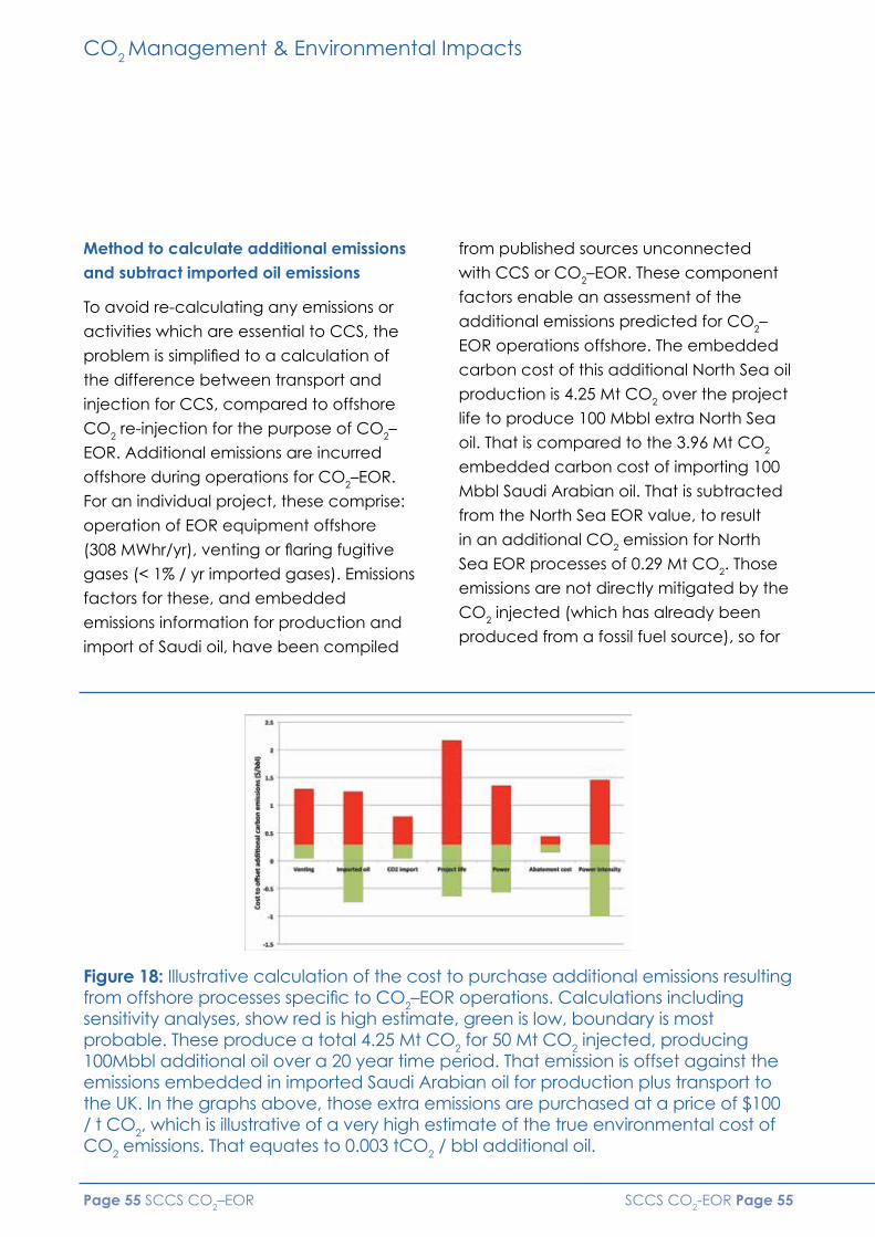
SCCS CO2-EOR Page 55 Page 55 SCCS CO2–EOR
Method to calculate additional emissions and subtract imported oil emissions
To avoid re-calculating any emissions or
activities which are essential to CCS, the
problem is simplified to a calculation of
the difference between transport and
injection for CCS, compared to offshore
CO2 re-injection for the purpose of CO2–
EOR. Additional emissions are incurred
offshore during operations for CO2–EOR.
For an individual project, these comprise:
operation of EOR equipment offshore
(308 MWhr/yr), venting or flaring fugitive
gases (< 1% / yr imported gases). Emissions
factors for these, and embedded
emissions information for production and
import of Saudi oil, have been compiled
from published sources unconnected
with CCS or CO2–EOR. These component
factors enable an assessment of the
additional emissions predicted for CO2–
EOR operations offshore. The embedded
carbon cost of this additional North Sea oil
production is 4.25 Mt CO2 over the project
life to produce 100 Mbbl extra North Sea
oil. That is compared to the 3.96 Mt CO2
embedded carbon cost of importing 100
Mbbl Saudi Arabian oil. That is subtracted
from the North Sea EOR value, to result
in an additional CO2 emission for North
Sea EOR processes of 0.29 Mt CO2. Those
emissions are not directly mitigated by the
CO2 injected (which has already been
produced from a fossil fuel source), so for
Figure 18: Illustrative calculation of the cost to purchase additional emissions resulting from offshore processes specific to CO2–EOR operations. Calculations including sensitivity analyses, show red is high estimate, green is low, boundary is most probable. These produce a total 4.25 Mt CO2 for 50 Mt CO2 injected, producing 100Mbbl additional oil over a 20 year time period. That emission is offset against the emissions embedded in imported Saudi Arabian oil for production plus transport to the UK. In the graphs above, those extra emissions are purchased at a price of $100 / t CO2, which is illustrative of a very high estimate of the true environmental cost of CO2 emissions. That equates to 0.003 tCO2 / bbl additional oil.
CO2 Management & Environmental Impacts

Page 56 SCCS CO2-EOR
illustration these additional emissions are
“purchased” by buying emissions credits
at a putative true cost of $100/tonne,
which greatly exceeds the 2015 EU market
price, CO2–EOR adds an additional cost of
0.3 $ / bbl additional oil.
Impact of accelerated delivery of CO2–EOR on UK CO2 emissions to 2050
At present, in 2015, there is no CCS
operational in the UK, and no CO2 is
stored. One benefit of CO2–EOR can be
conceptualised as creating a demand
for CO2, which removes costs of disposal
for power operators, and consequently
accelerates the development of CCS.
If EOR can accelerate CCS and CO2
storage, is that timing important? Here
we analyse the UK fossil power sector
CO2 storage to 2050, comparing a
Government DECC scenario of slow
CCS development against accelerated
development “push” CO2–EOR.
The “slow” and “high” baselines are from
DECC Roadmap for CCS (2012). Starting
in 2020, a low case of 3 GW CCS in 2030 is
proposed, and this analysis assumes new
operating CCS capacity rising linearly to
2050. A total of 122 Mt CO2 is stored 2020-
2050. We assume a “push” of 3x 2 GW
gas plant/yr, 5.5Mt CO2/yr, producing 2.42
TWh(e) / yr of grid electricity.
Figure 19: CO2 storage profile for 11 identical EOR-to-CCS increments starting in 2020, adding at one per year, 1,416 Mt CO2 could be stored by 2030 (black lines). Using an EOR-to-CCS scheme this total storage is only reduced by 58 Mt CO2 to 1358 Mt CO2 between 2020 and 2049, while producing 1,100 MM bbl of EOR-oil. Compare to DECC 2012 roadmap “slow rate” (yellow) and “fast rate“ (purple) of CCS.
CO2 Management & Environmental Impacts

SCCS CO2-EOR Page 57
A suite of CO2–EOR, converted to CCS
increments can commercialise a “UK
pathway” for CCS described by ETI (Day
2015), this requires 50 Mt/yr CO2 stored
by 2030 to decarbonise electricity. Each
increment produces 5.5 Mt CO2/yr, the first
increment commences in 2020 and ten
more start at one per year to meet this
goal. If CCS alone is deployed to meet
this goal, 54.5 Mt CO2 / yr is injected by
year 11 (2030), storing a total of 1,416
Mt CO2 by 2050. To use the commercial
advantage of CO2–EOR, then eleven EOR
increments would produce 1,100 MM bbls
of EOR-oil, which reduces Saudi oil imports
by 100 Mbbl/yr, from 2020 to 2049. After
each EOR project ceases, mandatory
CCS continues and Saudi oil imports re-
commence. This suite of projects stores
1,358 Mt CO2. The public funding route,
extrapolated linearly beyond 2030, is
substantially more expensive, and stores
much less CO2. By year 30 of CO2 storage
using “push” EOR, compared to the slower
public funding pathways, an additional
1.5x to 12.7x CO2 (500-1290 Mt) is stored by
2050.
CO2 Management & Environmental Impacts

Page 58 SCCS CO2-EOR
CO2–EOR: security of storage
Dr Gareth Johnson and Jamie Stewart – University of EdinburghDr Peter Olden and Dr Gillian Pickup – Heriot-Watt University
Preliminary studies from CO2–EOR in Canada have suggested that, in CO2–EOR settings,
solubility trapping takes place within both aqueous and hydrocarbon phases.
This study’s principal objective was to quantify how much solubility trapping takes place
within both aqueous and hydrocarbon phases in CO2–EOR settings.
The Pembina Cardium CO2 Monitoring
Pilot Project was used as a test site to
determine the relative roles of solubility
trapping. Firstly, two geochemical
approaches using empirical data from
the site (gas geochemistry, production
volumes and water isotope geochemistry)
were used to determine the phase
distribution of CO2 (dissolved or free-
phase) at a number of production wells
that were sampled monthly during a
two-year CO2 injection pilot. Secondly,
a simplified reservoir simulation was
performed to investigate various CO2
injection scenarios using a model with
some of the salient features of the pilot
project. In particular this model was used
to test the observations of the role of
solubility trapping versus free-phase CO2
trapping (Figure 20).
The two geochemical methods show that
the distribution of CO2 in the reservoir, and
hence the relative role of the trapping
mechanisms, is closely matched where
conditions permit both methods to work.
The initial reservoir model simulation
also closely matches the average
CO2 distribution and relative trapping
contributions derived from the
geochemical approaches, giving extra
confidence in both the methods using the
empirical data and the reservoir model
itself. After just two years of injection it is
shown that up to 26–32% of the injected
CO2 is solubility trapped.
Subsequently the reservoir model was
used to model a number of alternative
scenarios including: continuous CO2
injection, WAG, injection into a depleted
oil field and a saline aquifer. Results show
that additional CO2 storage by solubility
trapping is achieved when an oil phase
is present (25–50% solubility trapping
after 5 years of injection and 45 years of
equilibration) relative to a saline aquifer
(<25% solubility trapping after 5 years of
injection and 45 years of equilibration),
hence increasing CO2 security by
reducing the proportion of injected CO2
that remains as a buoyant free phase.
CO2 Management & Environmental Impacts

SCCS CO2-EOR Page 59
Figure 20: Relative contribution of trapping mechanisms for each modelled scenario over the first 45 years after CO2 injection
CO2 Management & Environmental Impacts

Page 60 SCCS CO2-EOR
Measurement, monitoring and verification: Enhanced oil recovery and carbon dioxide storageDr Gareth Johnson – University of Edinburgh
This desk based study assessed the differences between monitoring technology
requirements for CO2 storage in a saline or depleted hydrocarbon reservoir and in a
hydrocarbon reservoir, when CO2 injection is used for enhanced oil recovery (EOR) and it
is assumed monitoring is required to verify stored CO2.
First order factors dictating technology
choice including geological and
geographic parameters were assessed
before addressing differences introduced
by the choice of process (EOR or storage).
A brief review found the most common
monitoring technologies suitable for use
in either CO2 storage operations or in
CO2–EOR projects to not vary significantly,
although the measurements and analysis
do. It is found that the largest differences
in monitoring technology usage are not
process-related; rather they are controlled
by site-specific geology and geography.
However specific differences do exist
due to process choice from which the
following generalisations can be drawn:
Baseline measurements
Baseline measurements are typically
less complex for saline reservoirs due to
the unaltered state of the reservoir at
the onset of a storage project. Virtually
all technologies require a thorough
baseline assessment. As such, operations
in depleted oil and gas reservoirs and
EOR projects will typically require greater
assessment of baseline conditions due to
their altered state which may not have
reached equilibrium by the time of the
project start.
Characterisation
Depleted oil and gas reservoirs and
CO2–EOR projects will invariably be better
characterised before injection begins
than a saline reservoir. This increased
characterisation, in conjunction with
the knowledge that these reservoirs
have retained fluids on geological time
scales, reduces the risk of unplanned
CO2 migration. This in turn could lead
to less monitoring being required over
aerially extensive areas than would likely
be required in an uncharacterised saline
reservoir.
Thorough characterisation of a saline
reservoir, though costly, would also reduce
the risk of unplanned CO2 migration and
hence reduce monitoring requirements.
CO2 Management & Environmental Impacts

SCCS CO2-EOR Page 61
Number of wells
Depleted oil and gas reservoirs and
CO2–EOR projects will have more wells
penetrating the reservoir than a saline
reservoir. On the positive side, this opens
up more possibilities to deploy direct
(well-based) monitoring technologies.
A potential negative consequence is
that more potential CO2 migration routes
are introduced. However, these routes
are easily identifiable and monitoring
campaigns can be devised to manage
this risk.
Pressure
CO2–EOR projects will effectively manage
pressure by fluid production, reducing
the risk of exceeding caprock integrities,
re-activating faults and inducing seismic
events. This reduced risk will impact and
likely reduce the intensity of monitoring
required to assure CO2 storage integrity.
Depleted oil and gas reservoir storage
may in some cases (where either water-
flooding or natural water recharge has not
reinstated virgin pressure) have a reduced
pressure at the beginning of injection.
Hence, it may also have a lower risk of the
pressure-induced effects outlined above
and may thus benefit from a less intensive
monitoring campaign. Saline aquifers,
conversely, may have to actively manage
pressures to reduce this risk or otherwise
have more monitoring in place to detect
any such effects.
No specific different technologies or
monitoring strategies are recommended
for EOR over CO2 storage in either
saline or depleted oil and gas reservoirs.
Rather, it is recommended that the
local site-specific conditions of any CO2
injection project including the geology,
geography and the level of knowledge
and understanding of the reservoir are
assessed in order to build a risk-based
approach to selecting the appropriate
monitoring technologies and deployment
strategies (e.g., in Figure 21).
Figure 21: Possible monitoring technologies for a CO2–EOR project
Satellite InterferometrySpectral Imaging
Airborne EM, ER, GravimetrySpectral Imaging
Eddy Covariance
Surface EM, ER,andGravimetryNDIR GPR (<50m)Tiltmeters ESP
Monitor Wells
Well-Logs
Borehole/Cross-wellEM and ERT,Gravimetry
Borehole FluidSampling
VSP and Cross-well SeismicMicroseismic
Tracers
Soil Gas Concentrations
Surface 2D, 3D andMicroseismicInjection Well
CO2
CO2 Management & Environmental Impacts

Page 62 SCCS CO2-EOR
Environmental impacts of CO2–EOR: the offshore UK context Kit Carruthers – University of Edinburgh
The aim of this work was to determine the possible incremental environmental impacts of
future CO2–EOR projects in the UK North Sea, over and above those of the existing oil and
gas (O&G) industry. Offshore hydrocarbon extraction already has some environmental
impact; however, the work did not aim to quantify this. Instead, current offshore O&G
equipment and activities were determined and used to identify what would be unique,
or specific potential problems for CO2–EOR. These were determined to be: CO2 leakage;
CO2 stream impurities; enhanced trace element concentrations from geological storage;
enhanced radioactive scale.
Current regulatory environment
Environmental regulations for UK North
Sea oil and gas operators are set out
at international (EU), national (UK)
and local (e.g. Scotland) levels for
the offshore environment. Oil-in-water
(OIW) discharges to the North Sea are
strictly limited to 30 milligrams per litre
of produced reservoir fluids (“produced
water”), as per the 1992 Oslo–Paris
(OSPAR) Convention (as amended).
Any wastes generated offshore (solids
or liquids) must also comply with the
Radioactive Substances Act 1993 on
radioactivity, with activity levels set for
various naturally occurring radioactive
materials (NORM), and technologically
enhanced NORM, which may occur in
waste materials.
No legally binding limits are set,
however, for concentrations of
potentially environmentally damaging
trace elements such as mercury and
lead in produced waters. OSPAR
recommendations are that operators
adopt a risk-based approach to their
emissions, requiring that offshore
producers compare modelled
concentrations in produced fluids with
predicted no-effect concentrations
(PNEC) as set by OSPAR.
CO2 leakage to the marine environment
The use of CO2 is the main differentiator
between CO2–EOR and traditional
offshore O&G activities. CO2 may leak
from transport pipelines, return up wells
during injection, or escape geological
storage. When CO2 dissolves in water, the
partial pressure of CO2 increases, and the
pH is lowered.
CO2 Management & Environmental Impacts

SCCS CO2-EOR Page 63
Both can lead to stress in marine
organisms, including lowered body and
skeleton calcification, and hypercapnia
(increased CO2 in body tissue and fluids).
The effect of these can be to reduce
nutrient uptake, reproduction success,
metabolism and growth, and increase
mortality and deformities. The extent
of these effects depends on exposure
magnitude and duration, and species
type, trophic level and maturity.
Modelling of CO2 leakage scenarios,
e.g. pipeline leak versus geological
storage leak, appears to indicate that
the volumes of CO2 which interact with
seawater volumes are comparatively
small so that dilution and mixing quickly
occur. pH is therefore affected only to
very minor degree (less than 1pH unit
change) and/or is short lived before tidal
and current mixing dilute any changes.
Therefore, if CO2 leakage were to reach
the marine environment, organisms may
be subjected only to short duration and/
or highly localised events, and so effects
would likely be minimal.
Impurities in the captured CO2 stream
may include strong acids, and capture
and dehydration chemicals. They are
likely to be either chemicals routinely
used offshore, or to be in extremely
low concentrations to meet pipeline
specifications, and the likely additional
environmental impact is, therefore,
considered to be negligible compared
with current offshore activities.
Trace elements in produced water
Deep geological sandstone formations
targeted for CO2–EOR are saturated
with saline water, as well as oil. Since
CO2 dissolves in water to lower the pH,
this may promote the mobilisation of
rock-forming elements into solution.
The Department of Energy and Climate
Change (DECC) has identified a number
of elements as priorities for monitoring in
offshore discharges. These are: arsenic,
cadmium, chromium, copper, lead,
mercury, nickel and zinc. While some of
these elements (e.g. copper and zinc)
are essential nutrients, in large enough
concentrations they all exhibit toxicity
to marine life in similar fashion to CO2
hypercapnia. Unlike CO2, however, these
elements accumulate in organisms and
are magnified in concentration up the
food chain.
The O&G industry already produces
discharges containing these elements,
and there would only be a problem if the
concentrations resulting from
CO2–EOR projects are elevated above
current O&G industry levels. This was
estimated using laboratory batch
CO2 Management & Environmental Impacts

Page 64 SCCS CO2-EOR
Negligible Low Moderate Significant Severe
Negligible Low Moderate High Risk:
Impact
Like
lihoo
d N
eglig
ible
R
are
Occ
asio
nal
Pro
babl
e Fr
eque
nt
Trace Elements
CO2 Leak (Well)
CO2 Leak (Pipe)
CO2 Leak (Rock) Radioactive Scale Impurities (Pipe) Impurities (Well
and Rock))
experiments, where sandstone samples
from a North Sea oil field were reacted
with CO2 and saline water, to determine
whether CO2 significantly mobilises these
elements into solution.
Concentrations of the DECC elements of
interest are, on the whole, not significantly
increased with CO2. Furthermore,
experimental concentrations fall within
the range of values for existing O&G
operations. It is not expected, therefore,
that CO2–EOR activities will produce
trace element concentrations which are
significantly different to current offshore
activities.
Scale and radioactive scale
In the offshore context, scale is the
formation of sulphate and carbonate
minerals within O&G reservoirs, wells and
production equipment in response to
changes in fluid chemistry. These scales
can incorporate radioactive elements,
such as uranium and radium, which are
dissolved from minerals in the reservoir.
Figure 22: UKCS CO2–EOR Anchor Project Risk
CO2 Management & Environmental Impacts

SCCS CO2-EOR Page 65
CO2–EOR may enhance scale formation
due to mobilisation of scale-forming
elements. However, the routine use of
scale inhibitors in the O&G industry would
likely carry over to CO2–EOR with little
change in operations anticipated, and
therefore little additional environmental
impact.
The conceptual risk model
The results of the analysis of the potential
risks associated with CO2 leaks, CO2
impurities, trace element mobilisation,
and radioactive scaling were assessed
using a conceptual risk model. The
potential environmental impact of each
issue was plotted against the likelihood
of that impact occurring. This gives us the
potential risk of each case in a CO2–EOR
anchor project in the UK North Sea (see
Figure 22).
From Figure 21, we can see that CO2 leaks
from a well or trace element release from
produced waters are the most “risky”, but
both still represent low environmental risks.
Various mitigation options could be
deployed to further reduce risk, if required,
such as contingencies for stopping CO2
leaks, or the treatment of produced
waters to reduce trace element
concentrations. Overall, however,
CO2–EOR appears not to pose significantly
more environmental risk than current O&G
activities.
CO2 Management & Environmental Impacts

Page 66 SCCS CO2-EOR
Legal

SCCS CO2-EOR Page 67
Legal aspects of CO2-enhanced oil recovery Professor Richard Macrory - University College, London
Given the current depressed emissions trading market, projects that combine enhanced
oil recovery with long-term storage of carbon dioxide (CCS) for greenhouse gas
abatement purposes may prove vital in securing greater commercial investment for CCS.
A clear legal and regulatory framework will be a key element in providing confidence
for the future. In considering the relevant international, EU and national law that would
apply in the UK, we have identified some important problem areas and ambiguities in the
current legislation that should be addressed.
From a legal perspective, it is important
to distinguish generally between (i) pure
EOR operations where CO2 is injected
primarily as a means of extracting oil
or gas (although recycled as much as
possible during operations, some CO2
is inevitably left underground), and (ii)
EOR operations where CO2 is injected
for storage purposes, generally following
cessation of oil recovery itself. In contrast
to what is happening in jurisdictions such
as the USA, EOR operations in the UK in the
foreseeable future are likely to be offshore
and will use CO2 acquired from power
stations. The policy goals under the two
regimes are different, and it is unsurprising
that the regulatory requirements will
be distinct. CO2 storage operations are
designed to ensure the long-term disposal
of CO2, and far greater emphasis is
placed on ensuring site integrity as well
as on provisions concerning the eventual
transfer of site responsibility to the State.
International conventions
The main international marine conventions
of relevance are the 1996 London
Protocol and the OSPAR Convention.
The London Protocol does not expressly
mention EOR, but is unlikely to apply
to any injection of CO2 during EOR
operations because of the Protocol’s
definition of “dumping” which does not
apply to the disposal of wastes directly
arising from the exploitation of seabed
resources. But any storage taking place
following completion of EOR operations
will need to comply with the Protocol’s
provisions on CCS storage. Similarly,
the 1992 OSPAR Convention contains a
definition of “dumping” which means
it is unlikely to apply to any injection of
CO2 carried out in connection with EOR
operations.
Legal
Page 68 SCCS CO2-EOR
EU Directive
The Preamble to the 2009 EU CCS
Directive states that enhanced
hydrocarbon recovery (EHR) is not in itself
included in the scope of this Directive,
but that the provisions of the Directive
will apply where EHR is combined with
geological storage of CO2. Under general
principles of EU law, a Preamble by itself
cannot create an exemption, but acts as
an aid to interpretation of its substantive
provisions – it does not help clarity that
there is no explicit exemption in the
body of the Directive itself. As a result it
is possible to argue that the Directive will
apply to any injected CO2 during EOR
operations that is not recycled but left
underground. But it is more convincing to
interpret the Directive as applying only to
the storage of CO2 following the cessation
of EOR operations.
The EU Directive contains important
provisions concerning the acceptance
quality of CO2 injected into storage sites.
Essentially, these require that streams
consist “overwhelmingly” of CO2, and are
not contaminated by other substances
which might affect the integrity of the site
or pose environmental problems. There
are significant problems concerning the
application of the Directive’s requirements
on acceptance criteria for CO2 streams
where EOR operations combined with
long-term storage are involved. CO2 that
is injected underground for EOR purposes
inevitably becomes mingled with other
substances under the seabed including
gas and brine, and a strict interpretation
of the Directive’s provisions might
suggest that such CO2 could not meet
the acceptance criteria, and this could
severely inhibit EOR operations combined
with CCS storage. The drafting is probably
due to a failure at the time the legislation
was developed to fully appreciate
what was involved in an EOR combined
operation. Current guidelines issued by the
European Commission on acceptance
criteria do not address this issue, and the
Commission should be encouraged to
develop guidance on the subject.
Under the CCS Directive, CO2 injected
into a CCS site for long-term storage is
excluded from EU waste legislation. For a
combined operation, any injected CO2
should fall within the waste exclusion
since in such an operation one of the
purposes of capture and transporting
will be that of long-term storage, even
though it is used for EOR operations in the
intermediate period. Nevertheless, there
is potential ambiguity here, and it would
be preferable to secure a more clearly
worded exclusion from waste legislation
to encompass CO2 captured and
transported for a combined operation.
CO2 used in pure EOR operations cannot
fall within the exemption. Although CO2
emanating from a plant is therefore
potentially waste in law, it seems likely
Legal

SCCS CO2-EOR Page 69
that if it is transformed into a form suitable
for EOR operations it will have fulfilled
the criteria for ceasing to be waste in
law as long as it is being used during
EOR operations. “End of waste” criteria
for particular types of waste can be
developed at EU level but none have
been developed for yet for CO2 used
for EOR operations. Until that happens,
Member States are permitted to make
their own decisions applying the basic
principles of EU waste law, and it would be
helpful if guidance on this issue could be
developed by the relevant UK authorities.
National regulations
The CCS Directive requirements have
been transposed into UK law by the
Energy Act 2008 and regulations made
under it. These regulations apply to CO2
storage “with a view to its permanent
disposal” and as such do not apply to
CO2 injected during EOR operations.
However, the Energy Act anticipated
the issue of combined EOR and storage
operations by providing that the Secretary
of State can make an Order applying
the CCS requirements to EOR operations
in any particular site. No such Order has
yet been made but it is clearly a useful
mechanism to ensure clarity of controls.
In the absence of any such Order, pure
EOR operations fall under the Petroleum
Act 1998 and are regulated under
Seaward Production Licences issued by
the Secretary of State. In practice, where
EOR operations are followed by CO2
disposal, sequential licences are likely
to be issued, starting with a Seaward
Production Licence and later converting
into a Disposal Licence under the Energy
Act. It is therefore important to ensure
that the regimes are harmonised as far
as possible, and it appears at present
that there are no major inconsistencies.
Integration is helped by the fact that
at present both licensing regimes are
administered within a single organisational
unit within the Department of Energy and
Climate Change.
Other jurisdictions
By way of comparison we considered the
current legal controls for EOR operations
and CO2 disposal in a number of other
jurisdictions including the Netherlands,
France, Norway, Australia the USA
and Canada. As in the UK, pure EOR
operations are generally licensed under
different legal regimes from those
applicable to the long-term storage
of CO2, but with a recognition that the
dividing line between the two operations
is clearly not always easy to determine.
Of all the jurisdictions, the US
Environmental Protection Agency
currently appears to have the most
developed policy and guidelines to
determine whether and at what point
an EOR operation has become one for
CO2 storage, requiring distinct regulatory
requirements.
Legal

Page 70 SCCS CO2-EOR
The use of CO2 for enhanced oil recovery on the UKCS: Selected legal and regulatory issues with a specific focus on property Professor Roderick Paisley and Professor John Paterson – University of Aberdeen
There is growing interest in the use of CO2 for enhanced oil recovery (EOR), not least
on the UKCS. The economic use of this technology depends, however, upon a number
of practical challenges being overcome. Can the appropriate infrastructure be
established to ensure that sufficient quantities of CO2 are reliably available for all of
the fields wishing to make use of it? Is there sufficient demand to justify the necessary
investment? Are sufficient onshore sources available? Can the required transport network
be readily established via the reuse of existing infrastructure, or will new pipelines need
to be constructed? These technical challenges can sometimes mask underlying legal
issues which, if not properly addressed, could delay implementation or return to cause
problems for interested parties at a later date.
There are a variety of reasons that explain
why these legal issues are so problematic.
In relation to activities beyond the
territorial sea, for example, the difficulties
arise as a result of the relative uncertainty
that attends the rights that exist on
the continental shelf. This uncertainty
is further compounded by a general
willingness on the part of the state and
commercial actors during five decades
of oil and gas operations to turn a blind
eye to such issues. Difficulties also arise
beyond the territorial sea as a result of
the efforts of government over the past
decade to put a framework in place for
the development of offshore renewable
energy projects and of carbon capture
and storage. The fact that this framework
differs from that which underpins oil and
gas projects causes confusion. It is also the
case, however, that this very confusion
points out the direction in which a solution
may lie – specifically, the achievement of
some ultimate clarity as to the nature of
the Crown’s property rights beyond the
territorial sea.
Onshore, on the other hand, the difficulties
arise as a result of the fact that the
impact of property rights is not always
fully appreciated. For example, whilst a
servitude may exist to allow the transport
of hydrocarbons in one direction through
a pipeline that crosses property belonging
Legal

SCCS CO2-EOR Page 71
to another, it may not be sufficiently
broadly drafted to allow the transport
of CO2 in the other direction. Where a
pipeline involves dozens if not hundreds
of individual servitudes, this can create a
significant and potentially costly problem.
This report examines a range of issues
such as these with a view to highlighting
where there are problems and obstacles
facing the implementation of an extensive
pipeline network for the use of CO2 for
EOR as well as uncertainties relating to
liabilities. It begins by establishing some
fundamental propositions about the
nature of CO2 from a legal perspective,
including the extent to which it may
be subject to property rights and the
consequences that follow. It then goes
on to consider the position of the state
in various zones and notes both where
there is certainty as to its rights and
responsibilities in relation to the CO2 for
EOR and where there is uncertainty. In
the latter case, the report considers the
consequences of a range of different
scenarios. The penultimate section
considers some specific issues associated
with transportation to the seabed before
conclusions are presented in the final
section.
The legal – and specifically property
law – issues discussed in the report are
of fundamental importance to the
operability of CO2–EOR technology.
A key conclusion is that, where
uncertainties exist, clarification is required
in order to enable better drafting for
matters as diverse as funding, insurance,
indemnities, liabilities, and new regulation.
If this is not achieved, then unexpected
and potentially expensive problems
may arise, both for contractors and
the Crown. The position is all the more
confused because of the apparent
disjunction between the approach
adopted when CO2 is transported and
injected into the subsurface offshore
for purposes of sequestration and the
approach adopted when the same basic
processes are conducted for the purposes
of EOR. There appears to be no reason
for the differential approach from the
perspective of property law and, indeed,
every reason to conclude that what
currently exists is incoherent and the result
of ad hoc interventions as different issues
have emerged beyond the territorial sea.
Legal

Page 72 SCCS CO2-EOR
Legal
Transboundary chains for EU CO2–EORRudra Kapila and Professor Stuart Haszeldine – University of Edinburgh
CO2 storage is regulated by EU states within their exclusive economic zone (EEZ), of
up to 200 nautical miles. Transboundary issues are twofold: firstly, CO2 may originate in
one member state, to be injected beneath waters of a different state; secondly, fluid
movement after injection may physically relocate CO2 into pore space beneath the
waters of an adjacent member state. The issue of transboundary pressure interference is
not considered. Evidence was gained from reviewed publications, and “grey” reports,
as well as interviews with experts from seven stakeholder groups.
The two most relevant treaties are (i)
OSPAR, a modification to which was
ratified in 2007 “formally enabling”
cross-border transport for the purposes
of CO2 storage, including CO2–EOR; (ii)
the London Protocol which has enabled
CO2 storage since 2007. However,
transboundary movement of CO2 under
Article 6 has still to be ratified and requires
the agreement of two-thirds (i.e. 27 of
40) of the signatories to the Protocol. CO2
used for EOR will, though, be exempt,
as it is related to the exploitation of
seabed mineral resources, including
hydrocarbons. A second method to
enable transboundary CO2 movement is
that two states can bilaterally agree the
export of CO2 for storage.
Small quantities of CO2 for food and
drink are already moved as commodities
by ship between North Sea states, and
this provides a precedent, although
scaling this up 1,000 times may require
diplomatic support. It is unclear within the
CCS Directive if transport of CO2 by ship
removes liability to purchase EU- Emissions
trading scheme (EU-ETS) certificates,
even if CO2 is later securely disposed of
by EOR, because ships are outwith the
EU-ETS. A solution is for the state receiving
CO2, to designate those ships as EU-ETS
facilities. The International Code for the
Construction and Equipment of Ships
Carrying Liquefied Gases in Bulk (IGC
Code) for larger CO2 ships need to be
adapted, but multiple small vessels can
already work. The design concepts for
larger vessels are completed. From a legal
standpoint, shipping is seen as simpler –
with fewer and smaller liability and legacy
problems – than modifying or constructing
pipelines.
For transboundary chains of CO2 pipeline
transport, and storage sites which straddle
SCCS CO2-EOR Page 73
licence or international boundaries, the
existing legal approach to hydrocarbon
unitisation and cost sharing is likely to be
adaptable. To enable conversion of oil
fields to EOR, suitable fiscal incentives
are needed. For these EOR purposes,
CO2 should be legally defined as a
commodity, not a waste. However if an
EOR project transitions into being pure
CO2 storage, then the definition of CO2
as a waste triggers greater difficulties in
transport, monitoring, and certification of
storage – including the difficulty of export
from one state to another under the
London Protocol.
Liability concerns can be at state level,
usually undertaken by negotiation, and at
civil level EU liability law is not harmonious
between states. Diligence during normal
project evaluation by legal firms can
make multilateral private contract
consortium agreements. Bilateral state
agreements may be useful to define the
physical location of shipping under the
CCS Directive, or to allocate regulatory
responsibility and leakage liability for
cross-border pipelines or storage sites.
Private commercial contracts, adapted
from those for hydrocarbons, will need
to consider liability more closely than the
existing “loss of income” approaches
currently taken.
In summary, CO2–EOR project chains
face no special legal challenges around
the North Sea, provided that CO2 is
defined as a commodity not a waste.
When considering legal implications, CO2
shipping implies less cost and liability, but
may lose EU-ETS exemption if bilateral
agreements are not made. The EU
Commission needs to provide Directive
guidance to include CO2 shipping within
EU-ETS. Pipeline transport of CO2 for EOR
has no legal impediment. Successful
EOR projects could provide exemplars
to establish pragmatic ratification of
London Protocol Article 6, which currently
prohibits transboundary CO2 transfer.
Fiscal incentives are needed to stimulate
CO2–EOR investment, rather than
decommissioning. Liability frameworks
already exist in private contract law, but
need adaptation from hydrocarbons to
specific CO2–EOR risks.
Legal

Page 74 SCCS CO2-EOR
CO2 Supply

SCCS CO2-EOR Page 75
CO2 Supply
Ship transport of CO2 for enhanced oil recovery – literature survey Dr Peter Brownsort – SCCS
Transport of carbon dioxide (CO2) by ship may fulfil a key role in the development of CO2-
enhanced oil recovery (EOR) in the North Sea where a flexible transport system would be
advantageous. This survey aimed to determine the extent and scope of publications on
transport of CO2 by ship, to review a selection of available literature and to extract the
key findings of interest for CO2–EOR.
The full report gives an overview of
available literature and brief reviews of
the more important reports and papers
(Box 1), mostly from Japan, Korea and
mainland Europe. The literature establishes
that CO2 can be transported by ship using
known technologies, related to those
developed for liquefied petroleum gas
(LPG). Indeed, a small fleet of liquid CO2
carriers already operates in European
waters serving the industrial gas and
food and drink industry markets. Most
publications on CO2 shipping, however,
are focused on carbon capture and
storage (CCS) and few consider the
special requirements of CO2–EOR. In
particular, the interface between shipping
and well injection is not widely covered for
CO2–EOR.
Box 1
Mitsubishi Heavy Industries, 2004, Ship transport of CO2, IEAGHG Report No. PH4/30.
Svensson et al., 2004, Transportation systems for CO2 – application to carbon capture and storage.
Hegerland, Jørgensen and Pande, 2004, Liquefaction and handling of large amounts of CO2 for EOR.
Doctor et al., 2005, IPCC special report on carbon dioxide capture and storage: Chapter 4 – Transport of CO2.
Aspelund, Mølnvik and de Koeijer, 2006, Ship transport of CO2: technical solutions and analysis of costs, energy utilization, exergy efficiency and CO2 emissions.
Aspelund, 2010, ‘Gas purification, compression and liquefaction processes and technology for CO2 transport’ in Developments and innovation in CCS technology.
Omata, 2011, Preliminary feasibility study on CO2 carrier for ship-based CCS.
Vermeulen, 2011, CO2 Liquid Logistics Shipping Concept (LLSC) – overall supply chain optimization.
ZEP, 2011, The costs of CO2 transport.
Roussanaly, Bureau-Cauchois and Husebye, 2013, Costs benchmark of CO2 transport technologies for a group of various size industries.
Yoo et al., 2013, Development of CO2 terminal and CO2 carrier for future commercialized CCS market.

Page 76 SCCS CO2-EOR
Technology for CO2 shipping
Shipping of CO2 is most effective
as a liquid at temperature and
pressure conditions close to the triple
point; typically 6.5 bara at -52°C is
recommended. The main process
stages are shown in Figure 23. The
technology required is based on that
for other cryogenic liquids such as LPG
and liquefied natural gas. Liquefaction
equipment and its energy requirement
account for a large proportion of the cost
of CO2 shipping systems. Ship proposals
are generally based on well-established
LPG carrier designs; capacities of up to
100,000m3 have been proposed.
Ship loading and onshore offloading
employ conventional techniques for
cryogenic liquids; however, offshore
offloading at a storage/EOR site requires
novel techniques and is a main area of
technological uncertainty in the transport
system.
Several alternative single point mooring
and transfer technologies are available.
These may need adapting for CO2
handling and the optimum system is
likely to be location-specific. Liquid
CO2 must be warmed and pumped to
a temperature and pressure suitable
for injection; this will be specific to the
well and reservoir and will change with
maturity of the site. The expertise exists to
determine the project-specific conditions
and equipment required. Injection rates
achievable will also be specific to the
individual site. Optimising CO2 flow across
both transport and injection may have
cost implications that have yet to be
properly considered.
Intermediate storage of liquid CO2 is
necessary between liquefaction and ship
loading. Storage may also be needed
offshore for CO2–EOR as continuous
injection or specific injection profiles may
be needed. This potential requirement
for offshore storage has barely been
mentioned in the literature and evaluation
of its consequences for cost is another
significant gap in knowledge.
Figure 23: CO2 Ship transport chain – main process stages
CO2 Supply

SCCS CO2-EOR Page 77
Regulation and health, safety and environmental aspects
There are several areas of liquid CO2
transport by ship and associated
processes where hazards exist. However,
all publications reviewed imply or
conclude that risks can be controlled
to an acceptable level by application
of existing engineering practices and
procedures under an appropriate
regulatory framework. Liquid CO2 shipping
design and operation must comply with
the International Gas Carrier Codes that
also govern liquid petroleum gas (LPG)
and liquid natural gas (LNG) shipping;
these activities have a very good safety
record over an extensive period.
Asset flexibility, costs and financial risk
The potential role for shipping in the
development of CO2–EOR and CCS, first
proposed in the early 2000s, is generally
supported by the body of literature.
Shipping of liquid CO2 at large scale is
feasible with known technologies and can
provide a transport system that is flexible in
terms of space and time. Shipping allows
collection of CO2 from different source
locations or transport hubs and delivery to
different storage or EOR sites. It allows for
sequential addition of capacity as CCS
or EOR is deployed initially and during
growth. When storage/EOR projects
reach completion, shipping capacity can
supply new sites being developed. If CO2
ships are no longer required, they can
be converted for use as LPG carriers and
maintain their value.
Figure 24: Shipping costs
CO2 Supply

Page 78 SCCS CO2-EOR
Cost estimates for CO2 shipping systems
vary between studies, depending
on assumptions made for the main
parameters: scale, transport distance,
ship size, utilities costs, financial variables
and project lifetime. Estimated costs for
distances relevant to the North Sea range
between 10–30 €/t-CO2. The greatest
costs are associated with liquefaction
and the shipping operation. However,
compared to pipeline costs, CAPEX is
lower for shipping systems while OPEX is
higher. To generalise, total specific costs
of CO2 shipping are higher than pipelines
over short distances but lower over longer
distances (see Figure 24). The “break even
distance” varies between150–1,500km
depending on the specific assumptions of
the case studied.
The capital investment required for a liquid
CO2 shipping system is low compared to
the alternative of an offshore pipeline.
Together with the flexibility described, this
means shipping is seen as having relatively
low financial risk, which may benefit early
CCS or CO2–EOR projects. Methodologies
for estimating ship-based transport system
costs are available but costs cannot easily
be generalised, as they are case specific.
Overall, the costs of shipping CO2 can
be competitive with pipelines in the right
circumstances, generally where volumes
are lower and transport distances higher.
Several studies have found shipping
to be competitive at distance/volume
combinations relevant to EOR in the North
Sea.
Figure 25: Conceptual drawing of very large CO2 carrier, source Yoo et al, 2013
CO2 Supply

SCCS CO2-EOR Page 79
Worldwide comparison of CO2–EOR conditions Dr Peter Brownsort – SCCS
CO2 Supply
Comparison of fiscal and industry conditions in seven global regions where CO2–EOR is active or under consideration
The conditions for carbon dioxide enhanced oil recovery
(CO2–EOR) in seven major oil-producing regions have been
compared in terms of tax regime and incentives, general
regional availability of CO2, existing or potential infrastructure to
supply CO2 and the degree of maturity of CO2–EOR and carbon
capture and storage (CCS) in the region. The study suggests
that the UK would need to take major steps, such as introducing significant financial
incentives and state-supported provision of infrastructure, to be seen as a leading
contender for investment in CO2–EOR by multinationals, compared to other regions
where conditions are more favourable.
Taxes and incentives
Broadly speaking, oil taxes can be
divided into two groups based on either
production volume/value or net income.
The regions examined apply different
combinations and balances between
these. Corporate income taxes in
European jurisdictions are much higher
than in North America and Asia, although
production volume/value based taxes
and royalties in the latter regions make up
for this to some degree. Details of taxes,
including royalties and other charges,
and tax structures for each region are
given in Table 3. Specific incentives for
CO2–EOR, also summarised in Table 2, are
offered in certain circumstances against
taxes and/or royalties in the USA, Canada
and Malaysia. Tax credits for capture
of anthropogenic CO2 are offered to
source companies in the USA to increase
CO2 supply availability, as a preferred
alternative to incentivising EOR directly.
Differences in tax allowances, ring-
fencing rules and incentives mean a
straightforward comparison between
regions is difficult. A crude ranking of tax
burden (lowest to highest) for CO2–EOR
operations would suggest an order of
North America, Asia, Europe, but this
Regions compared:
Canada Norway
USA Onshore UK
China Malaysia
USA Gulf of Mexico

Page 80 SCCS CO2-EOR
Table 3: Comparison of oil taxes and incentives for EOR
Region Taxes applied to production value Taxes applied to net income Incentives
USA Onshore Summary: 12–38% of production value.Royalty – 12–30%, paid to rights owner; rate negotiated or result of bidding.Severance Tax – rates and tax base detail vary with state, generally based on gross production value at wellhead (example rates; Texas 4.6%, Alabama 8%; Alaska is different, 25% based on net value at pipeline end.
Summary: 35% net income.Combined federal and state rate against net cash income; state rate 0–12%, essentially deductible from federal rate. Not ring-fenced; can offset losses/deductions across whole company and value chain.
USA federal regime:15% of costs of EOR deductible when oil price low and 100% of costs of tertiary injection deductible – both subject to repeal proposals.Tax credits $10/t-CO2 for CO2–EOR and $20/t-CO2 for CCS, available to companies capturing anthropogenic CO2; total limited to 75Mt-CO2.USA individual states:Reductions or allowances against Severance Tax in Mississippi, North Dakota, Oklahoma, and pending in Florida.
USA Gulf of Mexico
Summary: 18.75-26.75% of production value.Royalty – 18.75% since March 2008. Previously 16.7% or, earlier, 12.5%. Severance Tax – only applies in state waters; rates and bases vary as for onshore.
Summary: 35% net income.Combined federal and state rate against net cash income; state rate 0–12%, essentially deductible from federal rate. Not ring-fenced; can offset losses/deductions across whole company and value chain.
As above.
Canada Summary: 10-45% of production value.Royalty – Crown Land royalties vary 10–45%; freehold royalties vary also, no detail found.
Summary: 25-31% net income.Federal rate (2013) 15%, state rate varies 10–16%. Charged on net income at corporate level; no ring-fencing.
Saskatchewan: Crown Royalty reduced to 1% of gross EOR revenue initially, increasing to 20%; freehold production tax reduced to 0% initially, increasing to 8%.Alberta: Royalties capped at 5% where eligible.
Malaysia Summary: 10% of production value.Developers require Production Sharing Contract (PSC) with PETRONAS, who take first 10% of volume as royalty, plus share of “profit oil” negotiated under contract. Also “signature bonus” paid to PETRONAS for contract. PSC not required in Malaysia–Thailand Joint Development Area (JDA).
Summary: 38% net income.Petroleum Revenue Tax (PRT) charged at 38% on net income from production and transport operations within Malaysia. Other operations subject to Income Tax of 25%. Lower PRT rates and progressive with time in JDA; arrangements in place with Thailand to avoid double taxation in JDA.
Annual investment allowances against PRT increased to 60–100%
China Summary: 6-21.5% of production value, or more.PSC required, “signature bonus” payable to state.Royalty – up to 12.5% for PSC prior to Nov 2011.Resource Tax – 5% of sales revenue offset by VAT and various exemptions, since Nov 2011.Mineral resources compensation fee – 1% of sales revenue.Special Oil Gain Levy – 20–40% of value above $55/bbl, i.e. progressive from 0% at $55/bbl to 15.5% at $100/bbl, and more for higher barrel values.
Summary: 25% net income.Many expenses including other taxes and levy deductible before income tax.
Norway Summary: 0% of production value.No royalty
Summary: 78% net income.Corporate Income Tax (CIT) 27%, on net operating profits.Resource Rent Tax 51%, on net operating profits of offshore extractive and transportation activities, including onshore supporting activities. Charged at corporate level; not ring-fenced, but limits to transfers of deductions between on- and offshore activities.
UK Summary: 0% of production value.No royalty.
Summary: 50–75% net income.Corporation Tax (CT) 30%, on profits from oil and gas exploration and production, ring-fenced, cannot offset losses in other parts of company/value chain.Supplementary Charge (SC) 20%, similar basis to CT, additive to CT (reduced from 32% in 2015 Budget).Petroleum Revenue Tax 50% (35% from 01/01/2016), charged for fields receiving development consent before March 1993, on profits calculated by statutory method on field basis; deductible from income before CT and SC.

SCCS CO2-EOR Page 81
should be treated with caution and will
depend on the specifics of project and
company involved.
Availability of CO2, infrastructure and experience
The availability of supply of CO2 to
potential EOR operations in the regions
compared was considered in terms
of absolute scale of CO2 sources in
the region, the location of sources,
the existing, planned or potential CO2
transport infrastructure available, together
with the degree of maturity of EOR and/
or CCS operations. Generally, these
factors are most advantageous for USA
Onshore, with Canada close behind, and
least favourable in Malaysia, with Norway
and the UK slightly more favoured. China
is intermediate as a whole, but with
more variation between factors. USA
Gulf of Mexico should share most of the
advantages of the neighbouring onshore
region; however, the existing demand
onshore, together with the increased
complexity of offshore operation, reduces
the favourability in terms of these factors.
The only region where infrastructure and a
market supplying CO2 for EOR are already
established is USA Onshore (see Figure 26),
with developments in Canada following
somewhat behind.
Figure 26: North American CO2–EOR operations and CO2 sources
CO2 Supply

Page 82 SCCS CO2-EOR
Offshore offloading of CO2 - Review of single point mooringDr Peter Brownsort – SCCS
CO2 Supply
There are many types of single point mooring (SPM) and loading systems that have
been developed for the transfer of hydrocarbon and other fluids from production wells,
platforms or floating storages to tankers. Several of them can probably be adapted for
transfer, in the opposite direction, of carbon dioxide (CO2) from transport ships to injection
wells for enhanced oil recovery (EOR) or geological storage.
This desk-based study looked at the types
of SPM available, their key characteristics
and potential suitability for CO2 offloading.
The study developed a flow-chart based
selection guide for a CO2 offloading
mooring, taking account of some
constraints of location, material and
equipment characteristics and operations.
It also considered the fit of potential
mooring systems to some generic process
route options for a CO2 ship transport chain.
Single point mooring types
Over 35 named offshore mooring/loading
systems are in use globally. These can be
grouped into eight categories, seven of
which are SPMs:
• Conventional (spread) moorings,
not SPM, sheltered waters only
• Articulated (e.g. single anchor leg,
articulated column)
• Buoy (e.g. catenary anchor leg,
vertical anchor leg)
• Fixed tower/jacket SPM
• Floating tower/spar SPM
• Submerged flexible riser (e.g. single
anchor loading, submerged
loading system)
• Submerged buoy (e.g. several
tightly tethered submerged buoy
systems, hybrid riser systems)
• Turret (swivelling manifold
integrated into vessel, internal or
external, fixed or disconnectable).
Selection of offloading system
The selection of a single point system
for offloading depends on a number of
factors including location of offloading
point, CO2 condition at transfer,
availability of suitable flexible hoses
and ship design. Most of these factors
are dependent on the individual case
involved and it is, therefore, not possible
to give a general recommendation

SCCS CO2-EOR Page 83
of offloading system. However, using
available information a tentative logic
flow-chart has been proposed to narrow
down options for single point offloading
systems (Figure 27).
Four key questions relate to (i) the need
for buffer storage at the offloading point;
(ii) process equipment available on the
ship; (iii) acceptability of permanently
submerged flexible hoses for supercritical
CO2 transfer; and (iv) dynamic positioning
capability of the ship. An assumption
was made that flexible hoses suitable for
cryogenic liquid CO2 transfer in, or under,
seawater are not available.
Using the flow-chart, four generic route
options were tested to give an initial
screening of potential CO2 offloading
systems (offshore offloading or near-
shore offloading to a pipeline terminal,
each with and without buffer storage
at offloading point). For each route
a number of possible systems were
identified. However, the routes involving
liquid CO2 offload to buffer storage have
more limited options.
Recommendations
• Detailed knowledge of the
downstream process design
(CO2 injection profile and
rate, injection temperature
and pressure, reservoir
properties, platform capabilities)
is needed before selecting a
suitable offloading system.
• Specialist advice on mooring and
offloading design is needed to
define a suitable system.
• Improved understanding of
the suitability of flexible hoses
for CO2 transfer would be
beneficial, particularly for
permanently submerged situations
and for cryogenic liquid transfer.
• The need for buffer storage after
offloading is a key question
that depends on design of the
injection operation; projects should
assess this factor critically before
progressing with transport chain
design.
CO2 Supply

Page 84 SCCS CO2-EOR
CO2 Supply
Fig
ure
27:
CO
2 o
ffsh
ore
offl
oa
din
g s
yste
m s
ele
ctio
n g
uid
e

SCCS CO2-EOR Joint Industry Project
This project was established to undertake a collaborative programme of work to develop an understanding of Enhanced Oil Recovery (EOR), with the aim of creating a commercial use for CO2 captured from power plants and industry. It has focused on areas of work to address issues that are of major importance to project developers that are looking to link CO2-EOR in the North Sea with CCS projects. The project was led by SCCS partners and funding has been provided by the Scottish Government, Scottish Enterprise, 2Co Energy Limited, Nexen Petroleum UK Ltd and Shell.
About SCCS and our partners Scottish Carbon Capture & Storage (SCCS) is an independent research partnership of British Geological Survey (BGS), Heriot-Watt University, the University of Aberdeen, the University of Edinburgh and the University of Strathclyde. It is the largest CCS research group in the UK and provides a single point of coordination for all aspects of CCS research, from capture engineering and geoscience to public engagement, policy and economics. www.sccs.org.uk
The views and opinions expressed by authors in this publication are those of the authors and do not necessarily reflect those of the project sponsors.
© University of Edinburgh, June 2015. A report published by Scottish Carbon Capture & StorageISBN: 978-0-9927483-2-6
Full or non-technical reports of the research summarised in this report can be found on the SCCS website at: www.sccs.org.uk/expertise/reports/sccs-co2-eor-joint-industry-project
SCCS would like to thank the following organisations for providing funding support to the SCCS CO2-EOR Joint industry project:
Scottish Government; Scottish Enterprise; 2CoEnergy; Nexen; Shell
Image Credits:
Front/rear cover © Dabarti CGI/Shutterstock
Page 24: Graphic © iDesign/Shutterstock and Image © Denphumi/Shutterstock
Page 39: Graphic © iluistrator/Shutterstock and Image © Will Robb Photography
Page 45: Graphic © IhorZigor/Shutterstock and Image © curraheeshutter/Shutterstock
Page 49: Graphic © iDesign/Shutterstock and Image © ssuaphotos/Shutterstock
Page 69: Graphic © Rashad Ashurov/Shutterstock and Image © Paolo Bona/Shutterstock
Page 76: Graphic © WladD/ShutterstockImage and Image © Visionsi/Shutterstock
The University of Edinburgh is a charitable body, registered in Scotland, with registration number SC005336.
Contributors to this report: Dr Peter Brownsort Kit Carruthers Dundas Consulting Element Energy Professor Stuart Haszeldine Dr Gareth JohnsonRudra Kapila Professor Alex Kemp Chris Littlecott Dr Leslie MabonProfessor Eric MacKay Professor Richard Macrory Bruno Meyvis Dr Peter Olden Professor Roderick Paisley Professor John Paterson Dr Gillian PickupDr Kris Piessens Jamie Stewart Jeremy Turk Professor Karen Turner Dr Kris Welkenhuysen
Editors: Dr Matthew Ball (SCCS) Indira Mann (SCCS) Gordon Sim (SCCS)Design: Gillian Kidd (University of Edinburgh) Nicola McDonald (bagelfishdesign.co.uk)Proof-reader: Alison Platts

Securing a low-carbon future for the UKSCCS is a research partnership of British Geological Survey, Heriot-Watt University, the University of Aberdeen, the University of Strathclyde and the University of Edinburgh. Our researchers are engaged in high-level CCS research as well as joint projects with industry, with the aim of supporting the development and commercialisation of CCS in the UK and abroad. www.sccs.org.uk