section xxxxx latchways constant force posts part 1 …
TRANSCRIPT

DIVISION 11– EQUIPMENT SECTION XXXXXX – MAINTENANCE AND FALL PROTECTION SYSTEMS
2/6/2019 XXXXX - 1
SECTION XXXXX
LATCHWAYS CONSTANT FORCE POSTS
PART 1 GENERAL
1.1 SYSTEM DESCRIPTION
A. Type of system required: Constant Force Posts (CFP(s)) Use with Latchways Lifeline or single point anchors
B. System location: Roof/ Wall/ Tower/ Fixed Ladder, Misc. Structure, etc…
C. Maximum number of workers on system at one time: ##
D. Systems environmental exposure: What are the service conditions (indoors, outdoors, corrosive environment)? What materials will be required (steel, hot dip galvanizing, stainless steel, marine grade stainless etc…)?
E. Workers task while on the system: Workers will walk along edge. Occasionally, workers are required to look over the edge. While walking, workers need to carry heavy objects.
F. Type of fall protection required: Fall Arrest
G. Additional information: Supporting Documents
H. Insurances required: Commercial Liability and Workers’ Comp.
1.2 RELATED SECTIONS
A. Section 03300 - Cast-In-Place Concrete
B. Section 03400 - Pre-Cast Concrete
C. Section 05100 – Structural Metal Framing
D. Section 05400 – Cold Formed Metal Framing
E. Section 05310 - Metal Deck
F. Section 06100 – Rough Carpentry
G. Section 07510 - Built-Up Roofing

DIVISION 11– EQUIPMENT SECTION XXXXXX – MAINTENANCE AND FALL PROTECTION SYSTEMS
2/6/2019 XXXXX - 2
H. Section 07700 - Roof Specialties and Accessories
I. Section 11010 - Maintenance Equipment
1.3 REFERENCES
A. Occupational Safety & Health Administration (OSHA)
1. 29 CFR 1910.28 (b) (1) & 29 CFR 1926.501(b) (1) - Occupational Health and Safety Standards General Industry & Construction: Duty to have fall protection
2. 29 CFR 1910.140(c) (11) (i-ii) & 29 CFR 1926.502(d) (8) - Safety and Health Regulations for General Industry & Construction: Horizontal Lifeline Design Requirements.
3. 29 CFR 1910.140(c) (13) (i-ii) & 29 CFR 1926.502(d) (15) (i-ii) - Safety and Health Regulations for General Industry & Construction: Anchorage Design Requirements.
4. 29 CFR 1910.66 (e) (1) (i) - General Industry: Powered Platform Installations -Affected parts of buildings.
B. American National Standards Institute (ANSI)
1. Z359.1 [2016] – The Fall Protection Code
2. Z359.3 [2017] – Safety Requirements for Positioning and Travel Restraint Systems.
3. Z359.6 [2016] – Specifications and Design Requirements for Active Fall Protection Systems.
4. Z359.11 [2014] – Safety Requirements for Full Body Harnesses.
5. Z359.12 [2009] – Connecting Components for Personal Fall Arrest Systems.
6. Z359.13 [2013] – Personal Energy Absorbers and Energy Absorbing Lanyards.
7. Z359.14 [2014] – Safety Requirements for Self-Retracting Devices for Personal Fall Arrest and Rescue Systems.
8. Z359.15 [2014] – Safety Requirements for Single Anchor Lifelines and Fall Arrester for Personal Fall Arrest Systems.
9. Z359.18 [2017] – Safety Requirements for Anchorage Connectors for Active Fall Protection Systems.
DIVISION 11– EQUIPMENT SECTION XXXXXX – MAINTENANCE AND FALL PROTECTION SYSTEMS
2/6/2019 XXXXX - 3
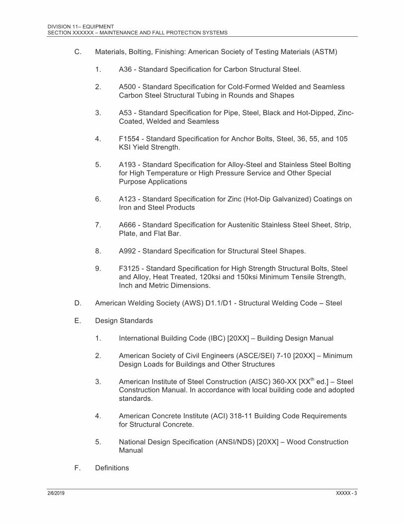
C. Materials, Bolting, Finishing: American Society of Testing Materials (ASTM)
1. A36 - Standard Specification for Carbon Structural Steel.
2. A500 - Standard Specification for Cold-Formed Welded and Seamless Carbon Steel Structural Tubing in Rounds and Shapes
3. A53 - Standard Specification for Pipe, Steel, Black and Hot-Dipped, Zinc-Coated, Welded and Seamless
4. F1554 - Standard Specification for Anchor Bolts, Steel, 36, 55, and 105 KSI Yield Strength.
5. A193 - Standard Specification for Alloy-Steel and Stainless Steel Bolting for High Temperature or High Pressure Service and Other Special Purpose Applications
6. A123 - Standard Specification for Zinc (Hot-Dip Galvanized) Coatings on Iron and Steel Products
7. A666 - Standard Specification for Austenitic Stainless Steel Sheet, Strip, Plate, and Flat Bar.
8. A992 - Standard Specification for Structural Steel Shapes.
9. F3125 - Standard Specification for High Strength Structural Bolts, Steel and Alloy, Heat Treated, 120ksi and 150ksi Minimum Tensile Strength, Inch and Metric Dimensions.
D. American Welding Society (AWS) D1.1/D1 - Structural Welding Code – Steel
E. Design Standards
1. International Building Code (IBC) [20XX] – Building Design Manual
2. American Society of Civil Engineers (ASCE/SEI) 7-10 [20XX] – Minimum Design Loads for Buildings and Other Structures
3. American Institute of Steel Construction (AISC) 360-XX [XXth ed.] – Steel Construction Manual. In accordance with local building code and adopted standards.
4. American Concrete Institute (ACI) 318-11 Building Code Requirements for Structural Concrete.
5. National Design Specification (ANSI/NDS) [20XX] – Wood Construction Manual
F. Definitions
DIVISION 11– EQUIPMENT SECTION XXXXXX – MAINTENANCE AND FALL PROTECTION SYSTEMS
2/6/2019 XXXXX - 4
1. Anchorage – per ANSI Z359.0 – A secure connecting point or a terminating component of a fall protection system capable of supporting impact forces applied by a fall protection system.
2. Anchorage Connector – per ANSI Z359.0 – A component or subsystem that functions as an interface between the anchorage and a fall protection, work positioning, rope access or rescue system for the purpose of coupling the system to the anchorage.
3. Clearance – per ANSI Z359.0 – The distance below an authorized person that must remain clear of obstructions in order to ensure that the authorized person does not make contact with any objects that would cause injury in the event of a fall.
4. Continuous Fall Protection – per ANSI Z359.0 – One or more fall protection systems that provide fall protection without interruption.
5. Fall Arrest – per ANSI Z359.0 – The action or event of stopping a free fall or the instant where the downward free fall has been stopped.
6. Fall Hazard – per ANSI Z359.0 – Any location where a person is exposed to a potential free fall.
7. Fall Restraint/Travel Restraint – per ANSI Z359.0 – A combination of anchorage, anchorage connector, lanyard (or other means of connection) and body support (full body harness) that limits travel in such a manner that the user is not exposed to a fall hazard.
8. Qualified Person – per ANSI Z359.0 – A person with a recognized degree or professional certificate and with extensive knowledge, training and experience in the fall protection and rescue field who is capable of designing, analyzing, evaluating and specifying fall protection and rescue systems to the extent required by the Z359 standards.
1.4 PERFORMANCE
A. System shall comply with 1.1 System Description
B. Performance Requirements
1. System Performance
a. The Anchor Post(s) shall provide a secure attachment means to the supporting structure in conjunction with the manufacturer’s requirements. The Anchor Post shall provide compatible connections with the applicable anchorage connector. All components shall be designed by the fall protection system supplier and shall meet the applicable fall protection ANSI standards and applicable OSHA regulations.

DIVISION 11– EQUIPMENT SECTION XXXXXX – MAINTENANCE AND FALL PROTECTION SYSTEMS
2/6/2019 XXXXX - 5
b. The Fall Protection Horizontal Lifeline System shall be designed to allow users to walk the entire length of the system without having to disconnect from the system to pass through intermediate support points. The system shall be designed to support required number of users in case of a fall and to prevent the users from free falling more than 6 feet. All components shall be designed by the fall protection system supplier and shall meet the applicable fall protection ANSI standards and applicable OSHA regulations.
2. Structural Performance:
a. Structure supporting the Horizontal Lifeline system must be capable of withstanding design loads as required by governing regulations and codes. Where component design loads are specified herein, they represent design minimum requirements.
b. Structure supporting Anchor Post(s) must be capable of withstanding the design loads as required by governing regulations and codes. Where component design loads are specified herein, they represent design minimum requirements.
c. All fall protection components and systems shall be designed with a minimum 2:1 safety factor per reference 1.3.A.2.
1.5 DESIGN
A. Design Requirements
1. CFP shall comply with current applicable OSHA, ANSI, and state regulations and standards.
2. The CFP and any supporting structure shall be designed by:
Latchways PLC Phone: 011-44-1380-732700 Hopton Pk Ind Est Website: www.latchways.com Devizes SN102JP UK E-mail: [email protected].
Gravitec Systems Inc. Phone: 1-800-755-8455 21291 Urdahl Road NW, Website: www.gravitec.com Poulsbo, WA 98370-7124 E-mail: [email protected].
3. General Requirements:
a. CFP(s) connection to structure shall be designed and installed, under the supervision of a Qualified Person, as part of a complete personal Fall Protection system.
b. CFP energy absorbers shall not be used to limit the maximum arrest force of the worker. CFP energy absorbers shall be used

DIVISION 11– EQUIPMENT SECTION XXXXXX – MAINTENANCE AND FALL PROTECTION SYSTEMS
2/6/2019 XXXXX - 6
only to control or reduce the maximum arrest load on the structure.
c. The design engineer shall ensure the increased clearance requirements of a deployed CFP will not conflict with the required clearance of the system.
d. CFP(s) shall satisfy the seismic conditions for nonstructural components as described by ASCE/SEI 7 and the most current edition of the IBC. No exceptions can be taken if the system is required to function for life-safety purposes after an earthquake.
e. Brackets and supports shall be attached to the structure with appropriate anchors of proper size to adequately support the intended loaded.
f. The designer shall take into account environmental factors (snow, ice, debris, etc...) when designing a CFP such that the CFP functions properly.
g. The CFP(s) shall comply with Latchways design requirements.
4. Restraint CFP(s) shall be designed per ANSI Z359.2 & ANSI Z359.6:
a. The CFP(s) shall prevent workers from reaching and falling into any open hole or off the edge of a working surface.
b. The CFP(s) shall comply with the requirements for fall arrest CFP(s) as indicated in this document.
c. Where a worker is using a full body harness the force on the worker’s body shall not exceed 400 lbs.
d. CFP(s) may be used in restraint systems; provided that the engineer has determined that the restraint forces will not cause the CFP(s) to deploy and ensures that the CFP extension in combination with other deformations of the restraint system will not permit the worker(s) to reach the fall hazard.
e. The use of fall restraint systems shall be limited to surfaces at or less than a slope of 4:12 from the horizontal. This is so a fall will not result in dynamic loading on the fall restraint system or where the authorized person could end up being suspended vertically from the system.
5. Fall Arrest CFP(s) shall be designed per ANSI Z359.2 & ANSI Z359.6:
a. The selection, design, and installation of fall arrest CFP(s) shall be performed under the supervision of a Qualified Person.

DIVISION 11– EQUIPMENT SECTION XXXXXX – MAINTENANCE AND FALL PROTECTION SYSTEMS
2/6/2019 XXXXX - 7
b. Anchorages designed for fall arrest systems shall have the strength capable of sustaining static loads applied in the directions permitted by the system of at least two times the maximum arresting force.
c. When more than one user is attached to a horizontal lifeline, the load on the lifeline can be determined using either lumped mass or sequential fall calculations as described in ANSI Z359.6 [6.3.6]
d. The swing fall shall comply with ANSI Z359.6 [5.3]
e. The clearance safety margin shall comply with ANSI Z359.6 [7.2.6.2]
B. Sub-System Requirements
1. Harnesses and Vertical Lifelines (VLLs) used with the system shall comply with ANSI Z359.1
2. Connecting Components (carabiners and snaphooks) used with the system shall comply with ANSI Z359.12
3. Energy Absorbing Lanyards (EALs) used with the system shall comply with ANSI Z359.13
4. Self Retracting Lifelines (SRLs) used with the system shall comply with ANSI Z359.14
C. The fall protection system shall be used exclusively for its designed use and shall be marked to prevent other uses.
D. The design shall take into consideration the potential uses of and loads on the fall protection system, in order to facilitate the prompt rescue of workers who may fall while attached to the system.
E. The CFPs shall be designed to meet BS EN ISO 2360:2003, 1000 hour salt spray test.
F. The manufacturer shall test the CFP design using a 660lb weight on various roof structures.
G. The CFPs shall properly deliver the same energy absorbing capacity in any direction of an applied load.
H. Each batch of CFPs shall be static, dynamic, salt spray, and x-ray tested.
I. Each component of the CFPs shall be batch marked or individually serial numbered.
DIVISION 11– EQUIPMENT SECTION XXXXXX – MAINTENANCE AND FALL PROTECTION SYSTEMS
2/6/2019 XXXXX - 8
1.6 SUBMITTALS
A. Submit under provisions of Section ##### – Submittal Procedures
B. Product Data: Latchways’ data sheet on each product to be used, including:
1. Preparation instructions and recommendations.
2. Storage and handling requirements and recommendations
3. Installation methods
C. Drawings and Calculations:
1. Drawings:
a. Show the layout of the system including where the system is located and the complete assembly of all components.
b. Include a specification of the number, location, and qualifications of workers using the system.
c. Clearly specify the equipment dimensions, materials, fabrication details, hardware, and installation instructions.
2. Calculations:
a. Calculations shall be prepared under the supervision of a registered Professional Engineer and Qualified Person.
b. Include a statement defining the type of system and indicating that the CRP attachment design is in accordance with the requirements of ANSI Z359.6.
3. The Professional Engineer who oversaw the design of the system shall affix their professional seal to each drawing and calculation package issued.
D. Operation and Maintenance Data shall be prepared per ANSI Z359.2 & ANSI Z359.6:
1. Include complete list of equipment replacement parts; identify each entry with the equipment description and part numbers.
2. Include technical information for servicing equipment.
3. Include legible “as-constructed” drawings of the installed system.
4. Include installation date and system owner’s name and address.

DIVISION 11– EQUIPMENT SECTION XXXXXX – MAINTENANCE AND FALL PROTECTION SYSTEMS
2/6/2019 XXXXX - 9
5. Include detailed operating procedures:
a. Written by a Qualified or Competent Person.
b. Identifying the CFP(s) location
c. Stating any safety precautions that shall be followed during access and egress.
d. Describing the limitation on use of system: maximum load, designated equipment, required clearance and maximum number of persons permitted to be attached to the system at one time.
e. Instructions for inspection, maintenance, and retirement of the system and all of its components, including how often inspection and maintenance are to be performed and a description of the qualifications required for persons performing these tasks.
f. Procedure for inspection:
I. Required or recommended inspection intervals.
II. Detailed instruction for inspecting each component of the system.
III. Description of acceptance or rejection criteria, including retirement criteria, of each component of the system.
IV. Fall protection procedures shall include a requirement that any incidents, including accidents or near misses, be investigated to determine if procedures can be improved.
6. Provide or direct the owner of the system or the employer of the workers using the system to develop and implement a rescue plan before the system is used.
1.7 QUALITY ASSURANCE
A. Single Source: Obtain all materials and equipment required under this section from a single supplier.
B. Designer/Installer Qualifications: Engage a single firm to assume undivided responsibility for the design and fabrication of all fall protection system components. Firm shall have a minimum of 5 years documented experience in the fabrication of such components similar to that required for this project. Additionally, the firm shall have a minimum of 5 years documented experience in the installation of such components and who offers a regular inspection and maintenance service on such systems.

DIVISION 11– EQUIPMENT SECTION XXXXXX – MAINTENANCE AND FALL PROTECTION SYSTEMS
2/6/2019 XXXXX - 10
C. Design Engineer: Employ a firm with a minimum of 10 years experience designing fall protection systems with a minimum of 5 systems installed in the previous 12 months. Who employs a registered Professional Engineer (PE), with evidence of being the principal PE on at least 3 fall arrest systems which have been in use for no less than 1 year prior to bid closing date.
D. Professional Engineer and Fall Protection Qualified Person: Shall oversee the fall protection systems’ design, such that all component items meet the “Structural Performance” requirements, including sizing and spacing of all attachments to the building structure and verify the design is compliant with all applicable OSHA and ANSI standards. Additionally, they must prepare, stamp and sign all required calculations; while also approving the system designer’s drawings.
E. Welding to be executed by certified welders in accordance with AWS requirements.
1.8 DELIVERY, STORAGE & HANDLING
A. Material delivery shall be coordinated with all effected entities.
B. Storage and Protection:
1. Store originally packaged materials in a cool, dry, and protected location.
2. Materials shall be in new condition and show no signs of damage.
1.9 SEQUENCING
A. Ensure that products of this section are supplied to affected trades in time to prevent interruption of construction progress.
1.10 WARRANTY
A. Manufacturer's standard one year warranty for materials and workmanship.
PART 2 PRODUCTS
2.1 MANUFACTURERS
A. Manufacturers shall comply with the Quality Assurance section of this documentation.
B. All supporting structure which connects the CFP(s) to the super structure shall be designed by:
Gravitec Systems Inc. Phone: 1-800-755-8455 21291 Urdahl Road NW, Website: www.gravitec.com Poulsbo, WA 98370-7124 E-mail: [email protected].

DIVISION 11– EQUIPMENT SECTION XXXXXX – MAINTENANCE AND FALL PROTECTION SYSTEMS
2/6/2019 XXXXX - 11
2.2 PRODUCTS
A. Latcheways PLC Hopton Pk Ind Est Devizes SN102JP UK
2.3 MATERIALS
A. Product
1. The system shall be a complete and turnkey complying with the performance and design criteria of this document.
2. The CFP(s) shall be the product of Latchways PLC.
3. Components: All system connectors, cables and bolts shall be stainless steel Type 316 or epoxy coated aluminum. Fabricated supports required for additional support may be carbon steel with a corrosion resistant coating. However a faying surface shall be used to prevent galvanic reactions.
4. Post Base Plate Connectors: Provide complete with required components for weatherproof mounting to the following surfaces:
a. Standing Seam Roof Type.
b. Composite Ribbed Roofing Type.
c. Metal Roofing Type.
d. Insulated Roof Deck Type.
e. Concrete Deck Type.
f. Timber Deck Type.
g. Non-Penetrating.
5. The CFP(s) shall be attached to the supporting structure with appropriate fasteners. The fasteners shall be designed to support a load on the fall protection system of 2 times the maximum design load without failure.
6. Provide all designed sub-system items per Section 1.5 (B) of this document.
B. Supporting Structure
1. Structural Components shall comply with the applicable standards:

DIVISION 11– EQUIPMENT SECTION XXXXXX – MAINTENANCE AND FALL PROTECTION SYSTEMS
2/6/2019 XXXXX - 12
a. Structural Steel: ASTM A36
b. Structural Tubing: ASTM A500 Grade B
c. Structural Bars, Plates, Shapes, and Sheet Piling: ASTM A6
d. Piping: ASTM A53
2. Fasteners shall comply with the applicable standards:
a. Structural Bolts: ASTM A325
b. Alloy-Steel and Stainless Steel Bolting: ASTM A193
3. Flashing and Sealing Material shall comply with the applicable standards:
4. Material substitutions shall be better than or equal to the requirements found in this section.
5 Fabrication
a. Fabricate work true to dimension, square, plumb, level, and free from distortion or defects detrimental to performance.
b. Coordinate the system with supporting structure.
c. Welding:
I. AWS D 1.1 as applicable.
II. If Butt welds are used, then surplus welding material is to be ground off to ensure exposed surfaces are smooth. Fillet welds shall not be ground.
III. Slag is to be removed from the materials surface.
6 Finishes
a. Hot Dipped Galvanizing: Comply with ASTM A123.
b. Powder Coat: Safety Yellow
2.4 CFP DESIGN
A. CFP design shall comply with the Design Requirement section of this document.
B. Steel design shall comply with AISC 14th ed.

DIVISION 11– EQUIPMENT SECTION XXXXXX – MAINTENANCE AND FALL PROTECTION SYSTEMS
2/6/2019 XXXXX - 13
C. Wood design shall comply with ANSI/NDS [2005]
D. Concrete design shall comply with ACI [2008]
E. Fall protection systems attached onto an existing or new structure shall comply with IBC [2009] and ASCE/SEI [2010]
PART 3 EXECUTION
3.1 INSTALLATION
A. Installation shall be performed by:
Gravitec Systems Inc. Phone: 1-800-755-8455 21291 Urdahl Road NW, Website: www.gravitec.com Poulsbo, WA 98370-7124 E-mail: [email protected].
B. Install in accordance with approved shop drawings and manufacturer’s instructions.
C. The Latchways Fall Protection System shall be installed under the direction of manufacturer’s authorized trained personnel and under the supervision of a Qualified Person.
D. Install anchorages and fasteners in accordance with their manufacturer’s recommendations to obtain the allowable working loads published in the product literature and in accordance with this specification.
E. Do not load or stress the Latchways Fall Protection System until all materials and fasteners are properly installed and ready for service.
F. Where bolting is used for fastening, no fewer than three threads are to be exposed and the nut is to be positively locked using a thread-locking fluid or the double nutting technique.
G. Dissimilar materials with greater than 0.15V shall be separated by a faying surface.
H. Constant Force posts must be secured to roof surface with waterproof mechanical connectors as approved.
3.2 FIELD QUALITY CONTROL
A. After the Latchways Fall Protection System is installed, Latchways approved authorized Qualified or Competent Person shall inspect and operate the system and shall make all final adjustments for proper operation.
3.3 ADJUSTMENTS AND FINAL INSPECTION

DIVISION 11– EQUIPMENT SECTION XXXXXX – MAINTENANCE AND FALL PROTECTION SYSTEMS
2/6/2019 XXXXX - 14
A. Verify that all manufactured units have been installed in accordance with specifications and details, and will function as intended. Adjust any items where necessary to ensure proper operation.
B. Provide a complete drawing set with any revisions to the design or layout of the fall protection system during installation.
3.4 OPERATOR TRAINING
A Provide a minimum of 4 hours of operator training after system has been installed. Training is to be for the users of the system conducted at the installation site.
3.5 MAINTENANCE, INSPECTION AND TESTING
A. Provide manufacturer maintenance, inspection and testing instructions.
B. Provide documentation that is consistent with applicable OSHA and ANSI standards.
END OF SECTION

6
Constant ForceFall Protection InnovationLatchways has taken the science of Constant Force and applied it to the fall protection industry providing an easy-to-install, reliable and cost-effective solution to rooftop safety.
The principles of fall arrest are based on effective load control. A system must be able to withstand the force of a person’s fall and absorb the energy generated. Traditionally this was achieved by attaching the system to the structure of the building with the anchor point absorbing the load. This inherently caused diffi culties for designers and installers as the system location was determined by the structural elements of the building.
System installation was time consuming as fi xings had to be made from above and below. Such an installation method can create issues regarding warranties, leakage and cold bridging.
Latchways’ Constant Force post does not need to be fi xed to the building structure therefore simplifying installation (see pages 8 & 9). The Constant Force technology allows the load generated in the event of a fall to be absorbed through the entire system, as illustrated in the graph below.
Constant Force post performancecompared against Rigid Anchor
Latchways’ primary focus is to supply engineered fall protection products for all areas of industry, construction and maintenance. Installations include stadia, retail outlets, transmission towers, industrial complexes and notable sites such as Eden Project, Pier 6 at Gatwick Airport, Hong Kong Airport and Grand Central Station in New York. Latchways has worked closely with the major roofi ng manufacturers to produce a full range of fall protection systems for all designs and types of roofs.
Quality products
Forc
e (
kN
)
40
35
30
25
20
15
10
5
38
Load absorbed by Constant Force post
Load absorbed by rigid anchor

7
In addition to ‘in-house’ evaluation, Latchways’ products are tested externally by notifi ed independent test bodies. All systems are CE marked and hold EC Declarations of Conformity.
Constant Force systems are recommended and approved for use by most roofi ng manufacturers.
Details of how the systems fi t on all major roof types can be found in Latchways’ ManSafe specifi ers manual available on request or by visiting www.latchways.com.
The key European standards are:
• EN 353-1 Personal Protective Equipment (PPE) against falls from a height. Specifi cation for guided type fall arresters on a rigid anchorage line
• EN 353-2 PPE against falls from a height. Guided type fall arresters including a fl exible anchor line
• EN 341 PPE against falls from a height—Descender devices
• EN 354 PPE against falls from a height—Lanyards
• EN 355 PPE against falls from a height—Energy absorbers
• EN 358 PPE for work positioning and prevention of falls from a height—Belts for work positioning and restraint and work positioning lanyards
• EN 360 PPE against falls from a height—Retractable type fall arresters
• EN 361 PPE against falls from a height—Full body harness
• EN 362 PPE against falls from a height—Connectors
• EN 363 PPE against falls from a height—Fall arrest systems
• EN 364 PPE against falls from a height—Test methods
• EN 795 PPE against falls from a height—Anchor devices— Requirements and testing
The key standard is EN 795 which relates to the anchor devices. Developments in technology mean that the nature of the anchor device has changed. As such, Latchways conduct full roofi ng system tests (6 m x 6 m) to replicate the in-situ installation. This is a minimum requirement where top-fi xed solutions are concerned.
ManSafe for Roofi ngLegislation and equipment standards
8
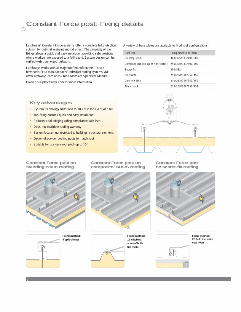
Constant Force post: Fixing details
Latchways’ Constant Force systems offer a complete fall protection solution for both fall restraint and fall arrest. The simplicity of the fi xings allows a quick and easy installation providing safe solutions where workers are exposed to a fall hazard. System design can be verifi ed with Latchways’ software.
Latchways works with all major roof manufacturers. To see how posts fi x to manufacturers’ individual roofi ng systems visit www.latchways.com or ask for a ManSafe Specifi ers Manual.
Email: [email protected] for more information.
Key advantages• System technology limits load to 10 kN in the event of a fall
• Top-fi xing ensures quick and easy installation
• Reduces cold bridging aiding compliance with Part L
• Does not invalidate roofi ng warranty
• System location not restricted to buildings’ structural elements
• Option of powder coating posts to match roof
• Suitable for use on a roof pitch up to 15°
A variety of base plates are available to fi t all roof confi gurations:
Roof type Fixing dimensions (mm)
Standing-seam 300/305/333/400/500
Composite and built-up-on-site (BUOS) 250/300/333/400/500
Secret-fi x 500/532
Steel deck 210/268/300/350/459
Concrete deck 210/268/300/350/459
Timber deck 210/268/300/350/459
Constant Force post on standing-seam roofi ng
Constant Force post oncomposite/BUOS roofi ng
Constant Force post on secret-fi x roofi ng
Fixing method: 4 split clamps
Fixing method: 16 stitching screws/bulb tite rivets
Fixing method: 20 bulb tite water seal rivets

9
Freestanding Constant Force postFreestanding Constant Force post is suitable for applications where roof penetration is not required or possible. It is available as a restraint or an arrest system and canbe used singularly or in series, varying the number of sections to suit the application.
Fixing method: 4 M8 mechanical fi xing anchorages
Fixing method: 4 toggle bolts
Fixing method: 4 toggle bolts
Consists of weighted segments
Dimensions of a 300 kg Freestanding Constant Force post
Constant Force post onconcrete deck fl at roofi ng
Constant Force post ontimber deck fl at roofi ng
Constant Force post onsteel deck fl at roofi ng
Freestanding Constant Force post on concrete deck fl at roofi ng
ManSafe for Roofi ngConstant Force post: Fixing details