section supplemental restraint system...
TRANSCRIPT

SRS-1
SUPPLEMENTAL RESTRAINT SYSTEM (SRS)
H RESTRAINTS
CONTENTS
C
D
E
F
G
I
J
K
L
M
SECTION
A
B
SRS
PRECAUTIONS .......................................................... 3Precautions for Supplemental Restraint System (SRS) “AIR BAG” and “SEAT BELT PRE-TEN-SIONER” .................................................................. 3Precautions for SRS “Air Bag” and “Seat Belt Pre-tensioner” Service .................................................... 3Wiring Diagrams and Trouble Diagnosis .................. 4
PREPARATION ........................................................... 5Special Service Tools ............................................... 5
SRS CONFIGURATION .............................................. 6Description ............................................................... 6
PASSENGER AIR BAG DEACTIVATION SWITCH (2-DOOR MODELS) .............................. 7
SRS Component Parts Location .............................. 7Direct-connect SRS Component Connectors ........... 8
TROUBLE DIAGNOSIS .............................................. 9Trouble Diagnoses Introduction ............................... 9
DIAGNOSIS FUNCTION ....................................... 9DIAGNOSIS MODE FOR CONSULT-II ................. 9HOW TO CHANGE SELF-DIAGNOSIS MODE WITH CONSULT-II .............................................. 10HOW TO CHANGE SELF-DIAGNOSIS MODE WITHOUT CONSULT-II ...................................... 10HOW TO ERASE SELF-DIAGNOSIS RESULTS ....11
How to Perform Trouble Diagnoses for Quick and Accurate Repair ..................................................... 12
INFORMATION FROM CUSTOMER .................. 12PRELIMINARY CHECK ...................................... 12WORK FLOW ...................................................... 13
Schematic .............................................................. 144-DOOR MODELS .............................................. 14
Wiring Diagram — SRS — ..................................... 152-DOOR MODELS .............................................. 154-DOOR MODELS .............................................. 17
Passenger Air Bag Deactivation Switch Indicator Operation Check .................................................... 20SRS Operation Check ............................................ 20
DIAGNOSTIC PROCEDURE 1 ........................... 20Trouble Diagnoses with CONSULT-II ..................... 21
DIAGNOSTIC PROCEDURE 2 ........................... 21
DIAGNOSTIC PROCEDURE 3 ........................... 26DIAGNOSTIC PROCEDURE 4 (CONTINUED FROM DIAGNOSTIC PROCEDURE 2) .............. 28DIAGNOSTIC PROCEDURE 5 ........................... 28
Trouble Diagnoses without CONSULT-II ................ 33DIAGNOSTIC PROCEDURE 6 ........................... 33DIAGNOSTIC PROCEDURE 7 ........................... 37DIAGNOSTIC PROCEDURE 8 (CONTINUED FROM DIAGNOSTIC PROCEDURE 6) .............. 38
Trouble Diagnoses: “AIR BAG” Warning Lamp Does Not Turn Off ............................................................ 39
DIAGNOSTIC PROCEDURE 9 ........................... 39Trouble Diagnoses: “AIR BAG” Warning Lamp Does Not Turn On ............................................................ 40
DIAGNOSTIC PROCEDURE 10 ......................... 40DIAGNOSIS SENSOR UNIT ..................................... 41
Removal and Installation ........................................ 41CRASH ZONE SENSOR ........................................... 42
Removal and Installation ........................................ 42FRONT SEAT BELT PRE-TENSIONER ................... 43
Removal and Installation ........................................ 43DRIVER AIR BAG MODULE AND SPIRAL CABLE ... 44
Removal and Installation ........................................ 44Removal ................................................................. 44Installation .............................................................. 46
FRONT PASSENGER AIR BAG MODULE .............. 48Removal and Installation ........................................ 48
REMOVAL ........................................................... 48INSTALLATION ................................................... 50
PASSENGER AIR BAG DEACTIVATION SWITCH ... 51Removal ................................................................. 51Installation .............................................................. 51
PASSENGER AIR BAG DEACTIVATION SWITCH LOCK CYLINDER ..................................................... 52
Removal ................................................................. 52Installation .............................................................. 52
PASSENGER AIR BAG DEACTIVATION SWITCH INDICATOR ............................................................... 53
Removal ................................................................. 53Installation .............................................................. 53
SRS-2
DISPOSAL OF AIR BAG MODULE AND SEAT BELT PRE-TENSIONER ..................................................... 54
Disposal of Air Bag Module and Seat Belt Pre-ten-sioner ...................................................................... 54
CHECKING DEPLOYMENT TOOL ..................... 54DEPLOYMENT PROCEDURES FOR AIR BAG MODULE (OUTSIDE OF VEHICLE) ................... 55DEPLOYMENT OF AIR BAG MODULE AND
SEAT BELT PRE-TENSIONER WHILE MOUNTED IN VEHICLE ......................................59DISPOSING OF AIR BAG MODULE AND SEAT BELT PRE-TENSIONER ......................................59
COLLISION DIAGNOSIS ..........................................60Collision Diagnosis ..................................................60
SRS INSPECTION ...............................................60

PRECAUTIONS
SRS-3
C
D
E
F
G
I
J
K
L
M
A
B
SRS
PRECAUTIONS PFP:00001
Precautions for Supplemental Restraint System (SRS) “AIR BAG” and “SEAT BELT PRE-TENSIONER” EHS000LU
The Supplemental Restraint System such as “AIR BAG” and “SEAT BELT PRE-TENSIONER”, used alongwith a front seat belt, helps to reduce the risk or severity of injury to the driver and front passenger for certaintypes of collision. This system may include seat belt switch inputs and dual stage front air bag modules. Ifequipped with dual stage front air bag modules, the SRS system uses the seat belt switches to determine thefront air bag deployment, and may only deploy one front air bag, depending on the severity of a collision andwhether the front occupants are belted or unbelted. Information necessary to service the system safely isincluded in the SRS and SB section of this Service Manual.
The vehicle may be equipped with a passenger air bag deactivation switch. Because no rear seat exists wherea rear-facing child restraint can be placed, the switch is designed to turn off the passenger air bag so that arear-facing child restraint can be used in the front passenger seat. The switch is located in the center of theinstrument panel, near the ashtray. When the switch is turned to the ON position, the passenger air bag isenabled and could inflate for certain types of collision. When the switch is turned to the OFF position, the pas-senger air bag is disabled and will not inflate. A passenger air bag OFF indicator on the instrument panel lightsup when the passenger air bag is switched OFF. The driver air bag always remains enabled and is not affectedby the passenger air bag deactivation switch.
WARNING:● To avoid rendering the SRS inoperative, which could increase the risk of personal injury or death
in the event of a collision which would result in air bag inflation, all maintenance must be per-formed by an authorized NISSAN/INFINITI dealer.
● Improper maintenance, including incorrect removal and installation of the SRS, can lead to per-sonal injury caused by unintentional activation of the system. For removal of Spiral Cable and AirBag Module, see the SRS section.
● Do not use electrical test equipment on any circuit related to the SRS unless instructed to in thisService Manual. SRS wiring harnesses can be identified by yellow and/or orange harnesses orharness connectors.
● The vehicle may be equipped with a passenger air bag deactivation switch which can be operatedby the customer. When the passenger air bag is switched OFF, the passenger air bag is disabledand will not inflate. When the passenger air bag is switched ON, the passenger air bag is enabledand could inflate for certain types of collision. After SRS maintenance or repair, make sure thepassenger air bag deactivation switch is in the same position (ON or OFF) as when the vehiclearrived for service.
Precautions for SRS “Air Bag” and “Seat Belt Pre-tensioner” Service EHS000FY
● Do not use a circuit tester to check SRS circuits unless instructed to in this Service Manual.● Before servicing the SRS, turn ignition switch OFF, disconnect both battery cables and wait at least 3 min-
utes.For approximately 3 minutes after the cables are removed, it is still possible for the air bags and seat beltpre-tensioners to deploy. Therefore, do not work on any SRS connectors or wires until at least 3 minuteshave passed.
● Air bag diagnosis sensor unit must always be installed with forward mark “⇐ ” pointing toward the front ofthe vehicle for proper operation. Also check air bag diagnosis sensor unit for deformities, dents, cracksand rust before installation and replace as required.
● The spiral cable must be aligned in the neutral position since its rotations are limited. Do not rotate steer-ing column while steering gear is removed to avoid damaging spiral cable.
● Handle air bag module carefully. Always place it with the pad side facing upward.● Conduct Self-diagnosis to check entire SRS for proper function after replacing any components. Refer to
SRS-20, "SRS Operation Check" .● After air bag inflates, the instrument panel assembly should be replaced if damaged.

SRS-4
PRECAUTIONS
Wiring Diagrams and Trouble Diagnosis EHS000G0
When you read wiring diagrams, refer to the following:● GI-13, "How to Read Wiring Diagrams"● PG-9, "POWER SUPPLY ROUTING" for power distribution circuitWhen you perform trouble diagnosis, refer to the following:● GI-9, "HOW TO FOLLOW TEST GROUPS IN TROUBLE DIAGNOSES"● GI-25, "How to Perform Efficient Diagnosis for an Electrical Incident"

PREPARATION
SRS-5
C
D
E
F
G
I
J
K
L
M
A
B
SRS
PREPARATION PFP:00002
Special Service Tools EHS000G1
The actual shapes of Kent-Moore tools may differ from those of special service tools illustrated here.
*: Special tool or commercial equivalent
Tool number(Kent-Moore No.)Tool name
Description
KV991072S0(J38381-KIT)Air bag deployment kitKV99106400(J38381)Deployment tool
Disposing of air bag module and seat belt pre-tensioner
—(J38381-80-A)Deployment tool adapter
For driver air bag module (4-door models) and seat belt pre-tensioner
KV99109000(J44230)Deployment tool adapter
For driver air bag module (2-door models)
—(J38381-65)Deployment tool adapter for front pas-senger air bag module
Connection between the deployment tool and front passenger air bag module (4-door mod-els)
KV991065S0(J38381-30)Deployment tool adapters
For passenger air bag module (2-door mod-els)
KV99105300(J41246)Air bag module bracket
Anchoring air bag module
—(J42057)Air bag master key set
Removing and installing accessory air bag locking bolts
S-NT357
WHIA0089E
LRS138
SHIA0173E
LHIA0010E
S-NT354
LRS210
SRS-6
SRS CONFIGURATION
SRS CONFIGURATION PFP:00000
Description EHS000GS
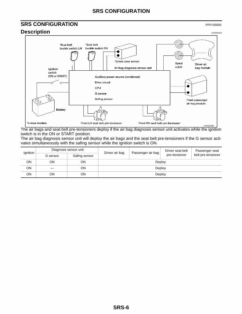
The air bags and seat belt pre-tensioners deploy if the air bag diagnosis sensor unit activates while the ignitionswitch is in the ON or START position.The air bag diagnosis sensor unit will deploy the air bags and the seat belt pre-tensioners if the G sensor acti-vates simultaneously with the safing sensor while the ignition switch is ON.
LHIA0018E
IgnitionDiagnosis sensor unit
Driver air bag Passenger air bagDriver seat belt pre-tensioner
Passenger seat belt pre-tensionerG sensor Safing sensor
ON ON ON Deploy
ON — ON Deploy
ON ON ON Deploy

SRS CONFIGURATION
SRS-7
C
D
E
F
G
I
J
K
L
M
A
B
SRS
PASSENGER AIR BAG DEACTIVATION SWITCH (2-DOOR MODELS)The vehicle (2-door models) is equipped with a passenger air bag deactivation switch which can be operatedby the customer. When the switch is turned to the ON position, the passenger air bag is enabled and couldinflate in a frontal collision. When the switch is turned to the OFF position, the passenger air bag is disabledand will not inflate in a frontal collision.After turning the ignition switch ON, the passenger air bag deactivation switch indicator on the instrumentpanel illuminates for bulb check. The indicator will remain illuminated if the passenger air bag deactivationswitch is in the OFF position. If the passenger air bag deactivation switch is in the ON position, the indicatorwill turn off after about 7 seconds.After SRS maintenance or repair, make sure the passenger air bagdeactivation switch is in the same position (ON or OFF) as when thevehicle arrived for service.
IGN OFF → ON
SRS Component Parts Location EHS000LL
WRS260
Passenger air bag deactivation switch position
Passenger air bag deactivation switch indi-cator
Passenger air bag deployment
ON Turns off within 7 seconds Enabled
OFF Remains illuminated Disabled
LHIA0020E
SRS-8
SRS CONFIGURATION
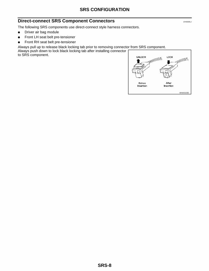
Direct-connect SRS Component Connectors EHS000LJ
The following SRS components use direct-connect style harness connectors.● Driver air bag module● Front LH seat belt pre-tensioner● Front RH seat belt pre-tensionerAlways pull up to release black locking tab prior to removing connector from SRS component.Always push down to lock black locking tab after installing connectorto SRS component.
WHIA0103E
TROUBLE DIAGNOSIS
SRS-9
C
D
E
F
G
I
J
K
L
M
A
B
SRS
TROUBLE DIAGNOSIS PFP:00004
Trouble Diagnoses Introduction EHS000GV
CAUTION:● Do not use electrical test equipment on any circuit related to the SRS unless instructed to in this
Service Manual. SRS wiring harnesses can be identified by yellow and/or orange harness connec-tors.
● Do not attempt to repair, splice or modify the SRS wiring harness. If the harness is damaged,replace it with a new one.
● Keep ground portion clean.
DIAGNOSIS FUNCTIONThe SRS self-diagnosis results can be read by using “AIR BAG” warning lamp and/or CONSULT-II. The read-ing of these results is accomplished using one of two modes — “User mode” and “Diagnosis mode”.The User mode is exclusively prepared for the customer (driver). This mode warns the driver of a system mal-function through the operation of the “AIR BAG” warning lamp.The Diagnosis mode allows the technician to locate and inspect the malfunctioning part.The mode applications for the “AIR BAG” warning lamp and CONSULT-II are as follows:
NOTE:Seat belt pre-tensioner malfunction is indicated by “AIR BAG” warning lamp.
DIAGNOSIS MODE FOR CONSULT-II● “SELF-DIAG [CURRENT]”
A current Self-diagnosis result (also indicated by the number of warning lamp flashes in the Diagnosismode) is displayed on the CONSULT-II screen in real time. This refers to a malfunctioning part requiringrepairs.
● “SELF-DIAG [PAST]”Diagnosis results previously stored in the memory are displayed on the CONSULT-II screen. The storedresults are not erased until memory erasing is executed.
● “TROUBLE DIAG RECORD”With TROUBLE DIAG RECORD, diagnosis results previously erased by a reset operation can be dis-played on the CONSULT-II screen.
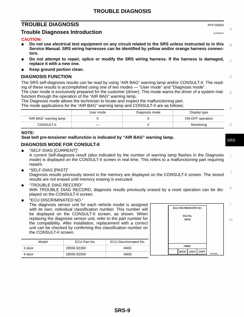
● “ECU DISCRIMINATED NO.”The diagnosis sensor unit for each vehicle model is assignedwith its own, individual classification number. This number willbe displayed on the CONSULT-II screen, as shown. Whenreplacing the diagnosis sensor unit, refer to the part number forthe compatibility. After installation, replacement with a correctunit can be checked by confirming this classification number onthe CONSULT-II screen.
User mode Diagnosis mode Display type
“AIR BAG” warning lamp X X ON-OFF operation
CONSULT-II — X Monitoring
Model ECU Part No. ECU Discriminated No.
2-door 28556 8Z300 A60C
4-door 28556 8Z500 A60D ARS366
SRS-10
TROUBLE DIAGNOSIS
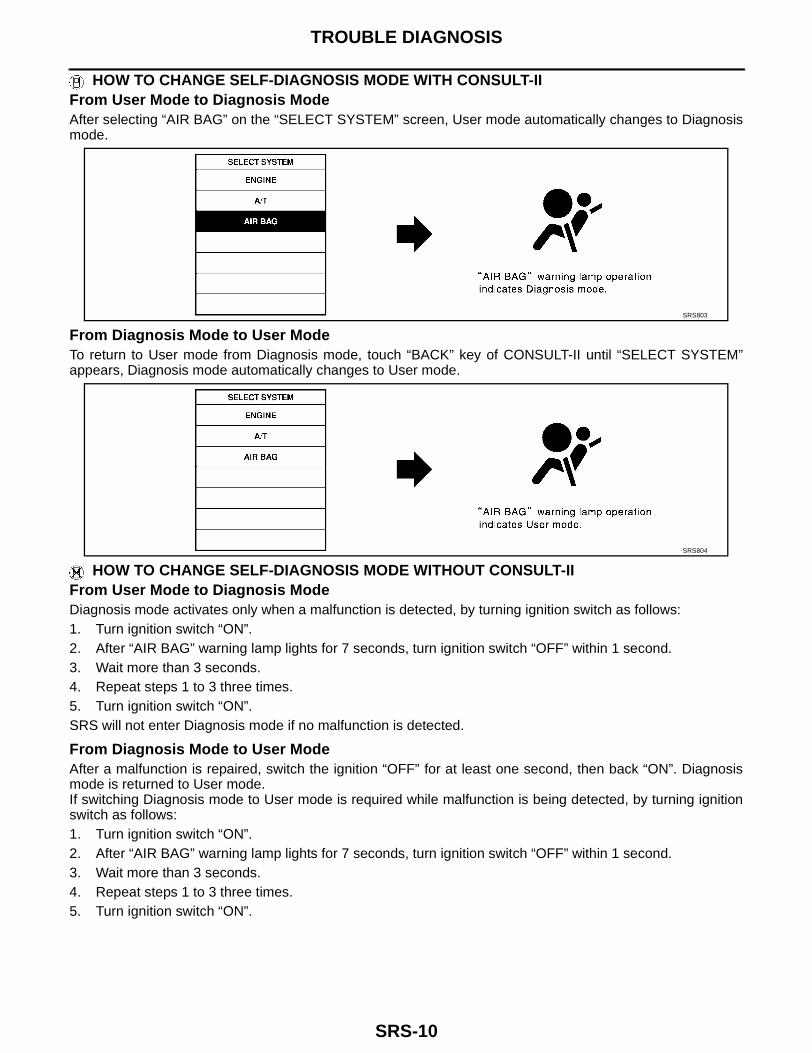
HOW TO CHANGE SELF-DIAGNOSIS MODE WITH CONSULT-IIFrom User Mode to Diagnosis ModeAfter selecting “AIR BAG” on the “SELECT SYSTEM” screen, User mode automatically changes to Diagnosismode.
From Diagnosis Mode to User ModeTo return to User mode from Diagnosis mode, touch “BACK” key of CONSULT-II until “SELECT SYSTEM”appears, Diagnosis mode automatically changes to User mode.
HOW TO CHANGE SELF-DIAGNOSIS MODE WITHOUT CONSULT-IIFrom User Mode to Diagnosis ModeDiagnosis mode activates only when a malfunction is detected, by turning ignition switch as follows:1. Turn ignition switch “ON”.2. After “AIR BAG” warning lamp lights for 7 seconds, turn ignition switch “OFF” within 1 second.3. Wait more than 3 seconds.4. Repeat steps 1 to 3 three times.5. Turn ignition switch “ON”.SRS will not enter Diagnosis mode if no malfunction is detected.
From Diagnosis Mode to User ModeAfter a malfunction is repaired, switch the ignition “OFF” for at least one second, then back “ON”. Diagnosismode is returned to User mode.If switching Diagnosis mode to User mode is required while malfunction is being detected, by turning ignitionswitch as follows:1. Turn ignition switch “ON”.2. After “AIR BAG” warning lamp lights for 7 seconds, turn ignition switch “OFF” within 1 second.3. Wait more than 3 seconds.4. Repeat steps 1 to 3 three times.5. Turn ignition switch “ON”.
SRS803
SRS804
TROUBLE DIAGNOSIS
SRS-11
C
D
E
F
G
I
J
K
L
M
A
B
SRS
HOW TO ERASE SELF-DIAGNOSIS RESULTS With CONSULT-II
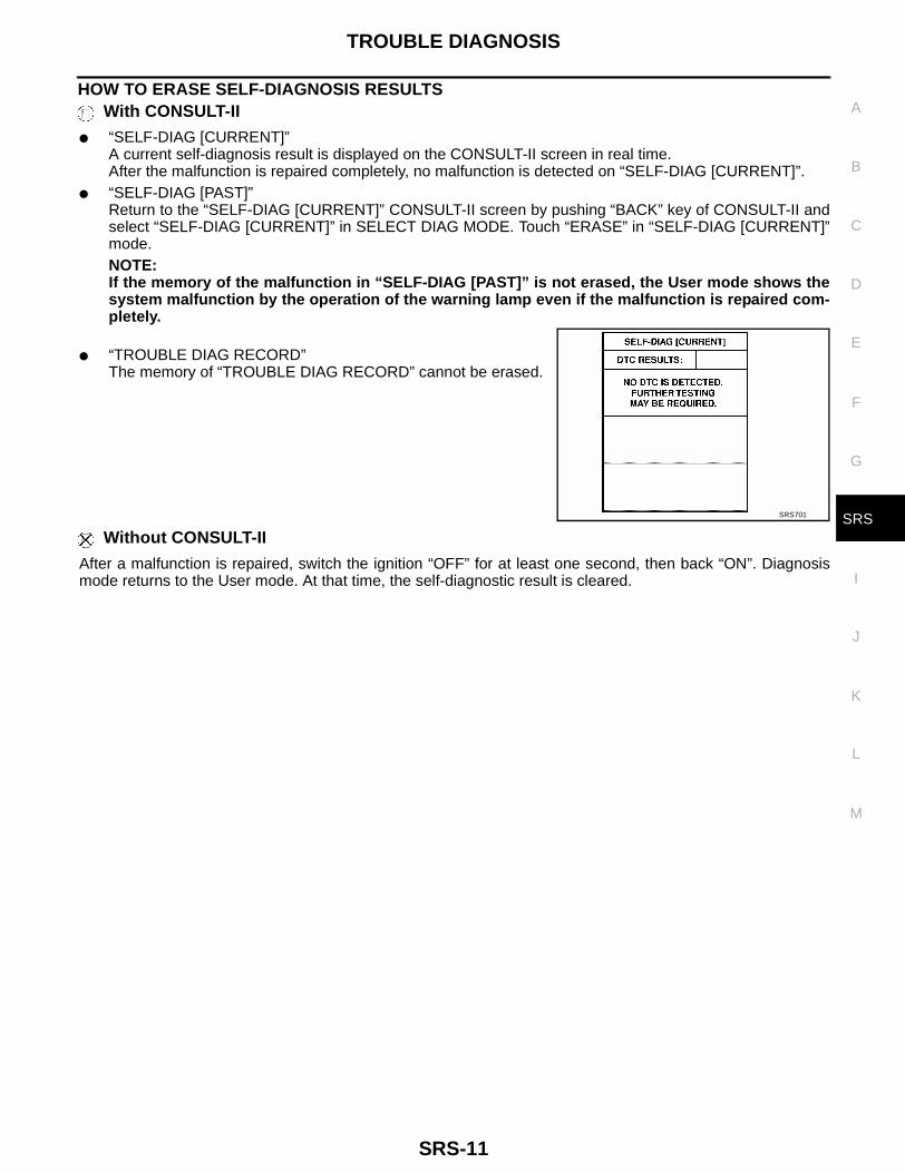
● “SELF-DIAG [CURRENT]”A current self-diagnosis result is displayed on the CONSULT-II screen in real time.After the malfunction is repaired completely, no malfunction is detected on “SELF-DIAG [CURRENT]”.
● “SELF-DIAG [PAST]”Return to the “SELF-DIAG [CURRENT]” CONSULT-II screen by pushing “BACK” key of CONSULT-II andselect “SELF-DIAG [CURRENT]” in SELECT DIAG MODE. Touch “ERASE” in “SELF-DIAG [CURRENT]”mode.NOTE:If the memory of the malfunction in “SELF-DIAG [PAST]” is not erased, the User mode shows thesystem malfunction by the operation of the warning lamp even if the malfunction is repaired com-pletely.
● “TROUBLE DIAG RECORD”The memory of “TROUBLE DIAG RECORD” cannot be erased.
Without CONSULT-II
After a malfunction is repaired, switch the ignition “OFF” for at least one second, then back “ON”. Diagnosismode returns to the User mode. At that time, the self-diagnostic result is cleared.
SRS701
SRS-12
TROUBLE DIAGNOSIS
How to Perform Trouble Diagnoses for Quick and Accurate Repair EHS000GW
A good understanding of the malfunction conditions can make troubleshooting faster and more accurate.In general, each customer feels differently about a malfunction. It is important to fully understand the symp-toms or conditions for a customer complaint.
INFORMATION FROM CUSTOMERWHAT..... Vehicle modelWHEN..... Date, FrequenciesWHERE..... Road conditionsHOW..... Operating conditions, Symptoms
PRELIMINARY CHECKCheck that the following parts are in good order.● Battery, refer to SC-4, "BATTERY"● Fuse● System component-to-harness connections

TROUBLE DIAGNOSIS
SRS-13
C
D
E
F
G
I
J
K
L
M
A
B
SRS
WORK FLOWNOTE:Seat belt pre-tensioner malfunction is indicated by “AIR BAG” warning lamp.
*1: SRS-12 *2: SRS-20 *3: SRS-21
*4: SRS-33 *5: SRS-26 *6: SRS-37
SRS799
SRS-14
TROUBLE DIAGNOSIS
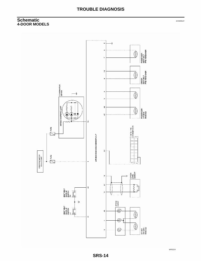
Schematic EHS000LR
4-DOOR MODELS
WRS224
TROUBLE DIAGNOSIS
SRS-15
C
D
E
F
G
I
J
K
L
M
A
B
SRS
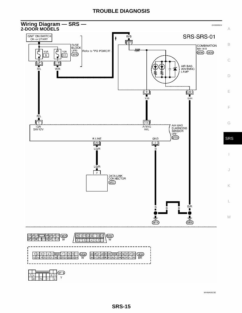
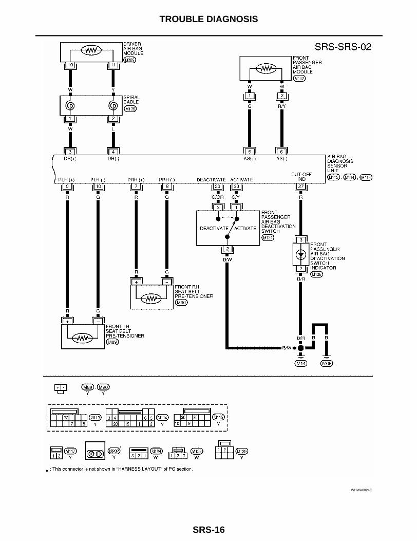
Wiring Diagram — SRS — EHS000GX
2-DOOR MODELS
WHWA0023E
SRS-16
TROUBLE DIAGNOSIS
WHWA0024E
TROUBLE DIAGNOSIS
SRS-17
C
D
E
F
G
I
J
K
L
M
A
B
SRS
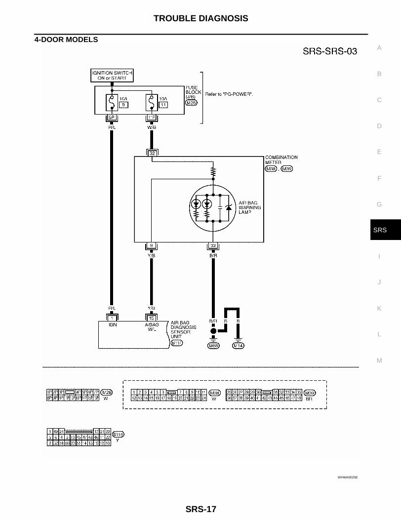
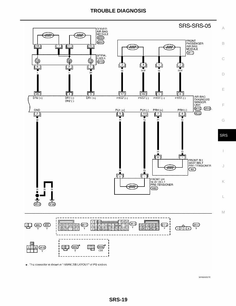
4-DOOR MODELS
WHWA0025E

SRS-18
TROUBLE DIAGNOSIS
LHWA0002E
TROUBLE DIAGNOSIS
SRS-19
C
D
E
F
G
I
J
K
L
M
A
B
SRS
WHWA0027E

SRS-20
TROUBLE DIAGNOSIS
Passenger Air Bag Deactivation Switch Indicator Operation Check EHS000GY
1. INDICATOR OPERATION CHECK
Check passenger air bag deactivation switch indicator operationwhen turning ignition switch ON with passenger air bag deactivationswitch in ON and OFF positions.
OK or NGOK >> Passenger air bag deactivation switch indicator opera-
tion is OK. Conduct “SRS Operation Check”. Refer toSRS-20, "SRS Operation Check" .
NG >> GO TO 2.
2. PERFORM SELF-DIAGNOSIS
Perform self-diagnosis using “AIR BAG” warning lamp in User mode. Refer to SRS-20, "SRS OperationCheck" .NOTE:The passenger air bag deactivation switch indicator can only be self-diagnosed when a malfunctionoccurs and indicator illumination does not correspond to switch position.OK or NGOK >> Replace passenger air bag deactivation switch including the key cylinder. Conduct “Passenger Air
Bag Deactivation Switch Indicator Operation Check” as a final check.NG >> Perform self-diagnosis using CONSULT-II or “AIR BAG” warning lamp in Diagnosis mode. Refer
to SRS-20, "SRS Operation Check" or SRS-33, "DIAGNOSTIC PROCEDURE 6" respectively. Ifthe passenger air bag deactivation switch indicator remains illuminated with the passenger air bagdeactivation switch ON, leave passenger air bag deactivation switch in ON position during diagno-sis. If the passenger air bag deactivation switch indicator does not illuminate with the passengerair bag deactivation switch OFF, leave the passenger air bag deactivation switch in the OFF posi-tion during diagnosis.
SRS Operation Check EHS000GZ
DIAGNOSTIC PROCEDURE 1Checking Air Bag Operation by Using “AIR BAG” Warning Lamp — User Mode1. After turning ignition switch from “OFF” to “ON”, “AIR BAG”
warning lamp operates.2. Compare “AIR BAG” warning lamp operation to the chart below.
Passenger air bag deactivation switch position
Passenger air bag deactivation switch indicator
ON Turns off within 7 seconds
OFF Remains illuminated
WRS260
SRS800
TROUBLE DIAGNOSIS
SRS-21
C
D
E
F
G
I
J
K
L
M
A
B
SRS
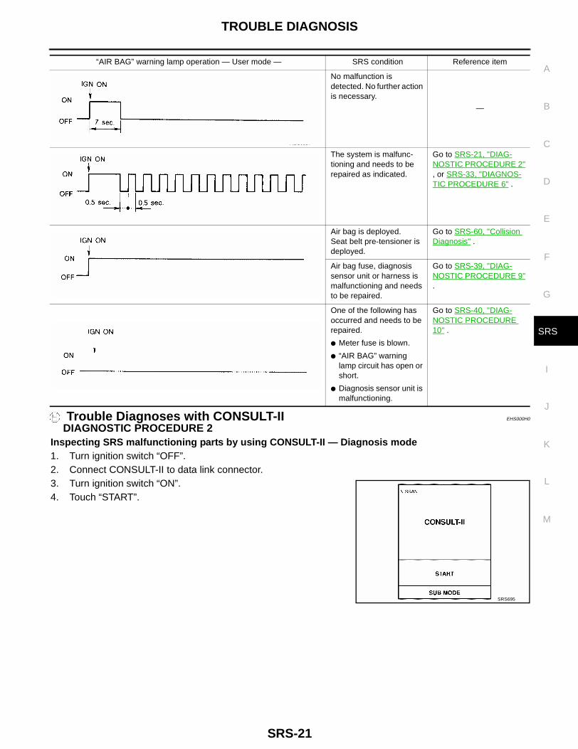
Trouble Diagnoses with CONSULT-II EHS000H0
DIAGNOSTIC PROCEDURE 2Inspecting SRS malfunctioning parts by using CONSULT-II — Diagnosis mode1. Turn ignition switch “OFF”.2. Connect CONSULT-II to data link connector.3. Turn ignition switch “ON”.4. Touch “START”.
“AIR BAG” warning lamp operation — User mode — SRS condition Reference item
No malfunction is detected. No further action is necessary.
—
The system is malfunc-tioning and needs to be repaired as indicated.
Go to SRS-21, "DIAG-NOSTIC PROCEDURE 2" , or SRS-33, "DIAGNOS-TIC PROCEDURE 6" .
Air bag is deployed.Seat belt pre-tensioner is deployed.
Go to SRS-60, "Collision Diagnosis" .
Air bag fuse, diagnosis sensor unit or harness is malfunctioning and needs to be repaired.
Go to SRS-39, "DIAG-NOSTIC PROCEDURE 9" .
One of the following has occurred and needs to be repaired.
● Meter fuse is blown.
● “AIR BAG” warning lamp circuit has open or short.
● Diagnosis sensor unit is malfunctioning.
Go to SRS-40, "DIAG-NOSTIC PROCEDURE 10" .
MRS095A
SRS695
SRS-22
TROUBLE DIAGNOSIS
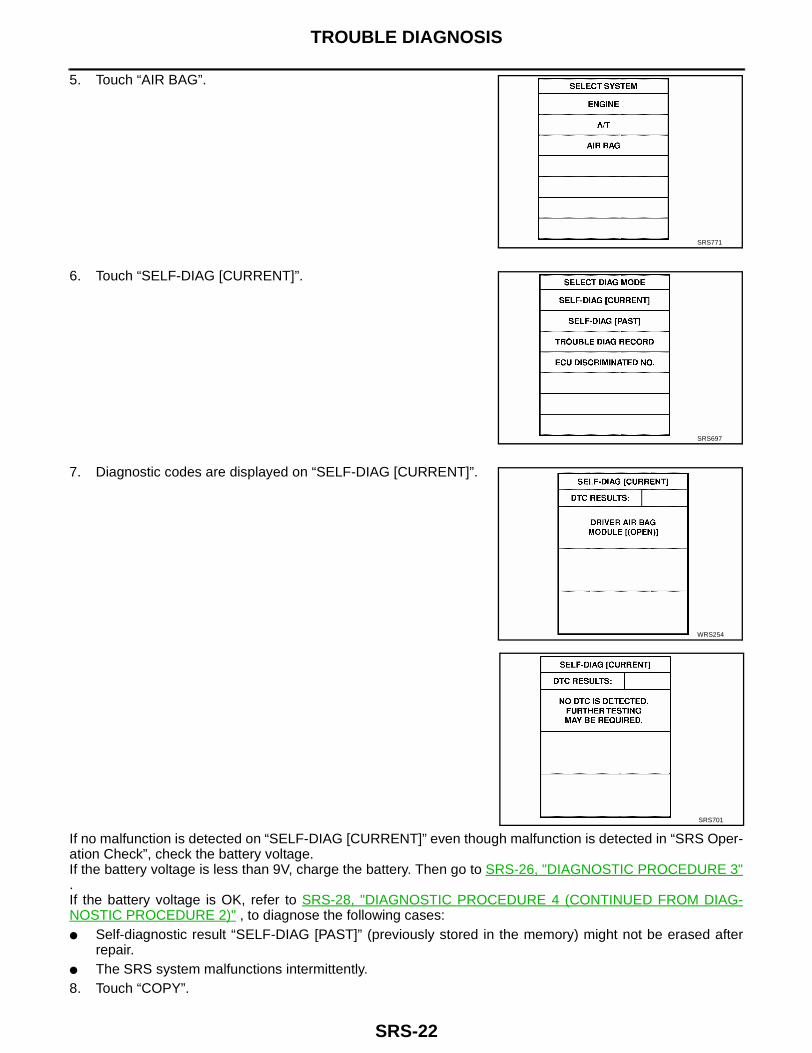
5. Touch “AIR BAG”.
6. Touch “SELF-DIAG [CURRENT]”.
7. Diagnostic codes are displayed on “SELF-DIAG [CURRENT]”.
If no malfunction is detected on “SELF-DIAG [CURRENT]” even though malfunction is detected in “SRS Oper-ation Check”, check the battery voltage.If the battery voltage is less than 9V, charge the battery. Then go to SRS-26, "DIAGNOSTIC PROCEDURE 3".If the battery voltage is OK, refer to SRS-28, "DIAGNOSTIC PROCEDURE 4 (CONTINUED FROM DIAG-NOSTIC PROCEDURE 2)" , to diagnose the following cases:● Self-diagnostic result “SELF-DIAG [PAST]” (previously stored in the memory) might not be erased after
repair.● The SRS system malfunctions intermittently.8. Touch “COPY”.
SRS771
SRS697
WRS254
SRS701

TROUBLE DIAGNOSIS
SRS-23
C
D
E
F
G
I
J
K
L
M
A
B
SRS
9. Compare diagnostic codes to “CONSULT-II Diagnostic Code Chart”. Refer to SRS-24, "CONSULT-II Diag-nostic Code Chart (“SELF-DIAG [CURRENT]”)" .
10. Touch “BACK” key of CONSULT-II until “SELECT SYSTEM” appears in order to return to User mode fromDiagnosis mode.
11. Turn ignition switch “OFF”, then turn off and disconnect CONSULT-II, and disconnect both battery cables.12. Repair the system as outlined by the “Repair order” in “CONSULT-II Diagnostic Code Chart”, that corre-
sponds to the self-diagnostic result. For replacement procedure of component parts, refer to the applica-ble Removal and Installation procedure.
13. After repairing the system, refer to SRS-26, "DIAGNOSTIC PROCEDURE 3" for final checking.

SRS-24
TROUBLE DIAGNOSIS
CONSULT-II Diagnostic Code Chart (“SELF-DIAG [CURRENT]”)
Self-diagnosis result ExplanationRepair order
*“Recheck SRS at each replace-ment.”
NO DTC IS DETECTED.
When malfunction is indicated by the “AIR BAG” warning lamp in User mode
● Low battery voltage (Less than 9V)
● Self-diagnosis result “ SELF-DIAG [PAST]” (previously stored in the memory) might not have been erased after repair.
● Intermittent malfunction has been detected in the past.
● Go to SRS-26, "DIAGNOSTIC PRO-CEDURE 3" after charging battery.
● Go toSRS-28, "DIAGNOSTIC PRO-CEDURE 4 (CONTINUED FROM DIAGNOSTIC PROCEDURE 2)" .
● No malfunction is detected. ● Go to SRS-26, "DIAGNOSTIC PRO-CEDURE 3" .
DRIVER AIRBAG MODULE[OPEN]
● Driver air bag module circuit is open (including the spiral cable). 1. Visually check wiring harness con-nections.
2. Replace harness if it has visible damage.
3. Replace spiral cable.
4. Replace driver air bag module. (Before disposing of it, it must be deployed.)
5. Replace air bag diagnosis sensor unit.
6. Replace the related harness.
DRIVER AIRBAG MODULE[VB-SHORT]
● Driver air bag module circuit is shorted to a power supply circuit (including the spiral cable).
DRIVER AIRBAG MODULE[GND-SHORT]
● Driver air bag module circuit is shorted to ground (including the spiral cable).
DRIVER AIRBAG MODULE[SHORT]
● Driver air bag module circuit is shorted between lines.
ASSIST A/B MODULE[OPEN]
● Passenger air bag module circuit is open. 1. Visually check wiring harness con-nections.
2. Replace harness if it has visible damage.
3. Replace passenger air bag module. (Before disposing of it, it must be deployed.)
4. Replace air bag diagnosis sensor unit.
5. Replace the related harness.
ASSIST A/B MODULE[VB-SHORT]
● Passenger air bag module circuit is shorted to a power supply circuit.
ASSIST A/B MODULE[GND-SHORT]
● Passenger air bag module circuit is shorted to ground.
ASSIST A/B MODULE[SHORT]
● Passenger air bag module circuit is shorted between lines.
PRE-TEN FRONT LH [OPEN]
● Driver seat belt pre-tensioner circuit is open. 1. Visually check wiring harness con-nections.
2. Replace harness if it has visible damage.
3. Replace the driver's seat belt. (before disposing the passenger seat belt pre-tensioner, it must be .)
4. Replace air bag diagnosis sensor unit.
5. Replace the related harness.
PRE-TEN FRONT LH [VB-SHORT]
● Driver seat belt pre-tensioner circuit is shorted to a power sup-ply circuit.
PRE-TEN FRONT LH [GND-SHORT]
● Driver seat belt pre-tensioner circuit is shorted to ground.
PRE-TEN FRONT LH [SHORT]
● Driver seat belt pre-tensioner circuit is shorted between lines.
PRE-TEN FRONT RH [OPEN]
● Passenger seat belt pre-tensioner circuit is open. 1. Visually check wiring harness con-nections.
2. Replace harness if it has visible damage.
3. Replace the front passenger's seat belt. (before disposing the passen-ger seat belt pre-tensioner, it must be activated.)
4. Replace air bag diagnosis sensor unit.
5. Replace the related harness.
PRE-TEN FRONT RH [VB-SHORT]
● Passenger seat belt pre-tensioner circuit is shorted to a power supply circuit.
PRE-TEN FRONT RH [GND-SHORT]
● Passenger seat belt pre-tensioner circuit is shorted to ground.
PRE-TEN FRONT RH [SHORT]
● Passenger seat belt pre-tensioner circuit is shorted between lines.
TROUBLE DIAGNOSIS
SRS-25
C
D
E
F
G
I
J
K
L
M
A
B
SRS
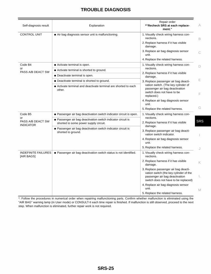
*: Follow the procedures in numerical order when repairing malfunctioning parts. Confirm whether malfunction is eliminated using the“AIR BAG” warning lamp (in User mode) or CONSULT-II each time repair is finished. If malfunction is still observed, proceed to the nextstep. When malfunction is eliminated, further repair work is not required.
CONTROL UNIT ● Air bag diagnosis sensor unit is malfunctioning. 1. Visually check wiring harness con-nections.
2. Replace harness if it has visible damage.
3. Replace air bag diagnosis sensor unit.
4. Replace the related harness.
Code B4orPASS A/B DEACT SW
● Activate terminal is open. 1. Visually check wiring harness con-nections.
2. Replace harness if it has visible damage.
3. Replace passenger air bag deacti-vation switch. (The key cylinder of passenger air bag deactivation switch does not have to be replaced.)
4. Replace air bag diagnosis sensor unit.
5. Replace the related harness.
● Activate terminal is shorted to ground.
● Deactivate terminal is open.
● Deactivate terminal is shorted to ground.
● Activate terminal and deactivate terminal are shorted to each other.
Code B5orPASS A/B DEACT SW INDICATOR
● Passenger air bag deactivation switch indicator circuit is open. 1. Visually check wiring harness con-nections.
2. Replace harness if it has visible damage.
3. Replace passenger air bag deacti-vation switch indicator.
4. Replace air bag diagnosis sensor unit.
5. Replace the related harness.
● Passenger air bag deactivation switch indicator circuit is shorted to some power supply circuit.
● Passenger air bag deactivation switch indicator circuit is shorted to ground.
INDEFINITE FAILURES[AIR BAGS]
● Passenger air bag deactivation switch status is not identified. 1. Visually check wiring harness con-nections.
2. Replace harness if it has visible damage.
3. Replace passenger air bag deacti-vation switch (the key cylinder of the passenger air bag deactivation switch does not have to be replaced)
4. Replace air bag diagnosis sensor unit.
5. Replace the related harness.
Self-diagnosis result ExplanationRepair order
*“Recheck SRS at each replace-ment.”

SRS-26
TROUBLE DIAGNOSIS
DIAGNOSTIC PROCEDURE 3Final checking after repairing SRS by using CONSULT-II —Diagnosis mode1. After repairing SRS, connect both battery cables.2. Connect CONSULT-II to data link connector.3. Turn ignition switch ON.
4. Touch “START”.
5. Touch “AIR BAG”.
6. Touch “SELF-DIAG [CURRENT]”.
LEC104A
SRS695
SRS771
SRS697
TROUBLE DIAGNOSIS
SRS-27
C
D
E
F
G
I
J
K
L
M
A
B
SRS
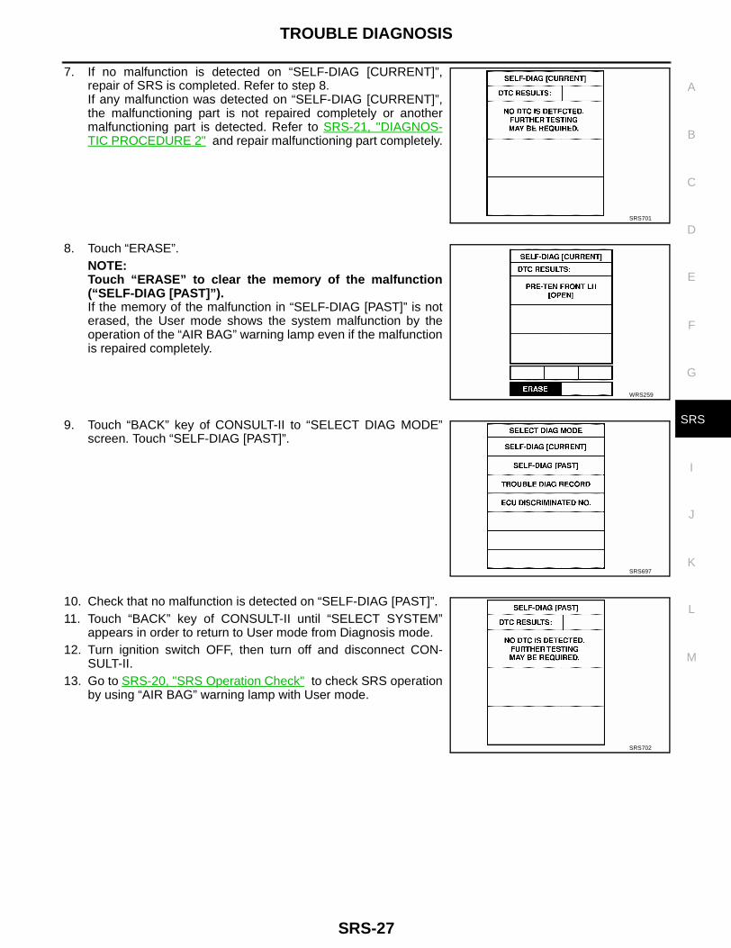
7. If no malfunction is detected on “SELF-DIAG [CURRENT]”,repair of SRS is completed. Refer to step 8.If any malfunction was detected on “SELF-DIAG [CURRENT]”,the malfunctioning part is not repaired completely or anothermalfunctioning part is detected. Refer to SRS-21, "DIAGNOS-TIC PROCEDURE 2" and repair malfunctioning part completely.
8. Touch “ERASE”.NOTE:Touch “ERASE” to clear the memory of the malfunction(“SELF-DIAG [PAST]”).If the memory of the malfunction in “SELF-DIAG [PAST]” is noterased, the User mode shows the system malfunction by theoperation of the “AIR BAG” warning lamp even if the malfunctionis repaired completely.
9. Touch “BACK” key of CONSULT-II to “SELECT DIAG MODE”screen. Touch “SELF-DIAG [PAST]”.
10. Check that no malfunction is detected on “SELF-DIAG [PAST]”.11. Touch “BACK” key of CONSULT-II until “SELECT SYSTEM”
appears in order to return to User mode from Diagnosis mode.12. Turn ignition switch OFF, then turn off and disconnect CON-
SULT-II.13. Go to SRS-20, "SRS Operation Check" to check SRS operation
by using “AIR BAG” warning lamp with User mode.
SRS701
WRS259
SRS697
SRS702

SRS-28
TROUBLE DIAGNOSIS
DIAGNOSTIC PROCEDURE 4 (CONTINUED FROM DIAGNOSTIC PROCEDURE 2)Inspecting SRS malfunction record
1. CHECK FOR PROBLEM CODE THAT MIGHT NOT HAVE BEEN ERASED AFTER PREVIOUS REPAIR
Is it the first time for maintenance of SRS?Yes or NoYes >> Go to SRS-28, "DIAGNOSTIC PROCEDURE 5" .No >> Self-diagnosis result “SELF-DIAG [PAST]” (previously stored in the memory) might not have been
erased after repair. Go to SRS-26, "DIAGNOSTIC PROCEDURE 3" .
DIAGNOSTIC PROCEDURE 5Inspecting SRS intermittent malfunction by using CONSULT-II— Diagnosis mode1. Turn ignition switch OFF.2. Connect CONSULT-II to data link connector.3. Turn ignition switch ON.
4. Touch “START”.
5. Touch “AIR BAG”.
LEC104A
SRS695
SRS771
TROUBLE DIAGNOSIS
SRS-29
C
D
E
F
G
I
J
K
L
M
A
B
SRS
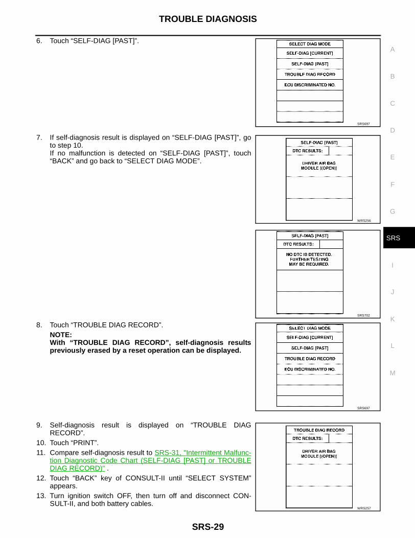
6. Touch “SELF-DIAG [PAST]”.
7. If self-diagnosis result is displayed on “SELF-DIAG [PAST]”, goto step 10.If no malfunction is detected on “SELF-DIAG [PAST]”, touch“BACK” and go back to “SELECT DIAG MODE”.
8. Touch “TROUBLE DIAG RECORD”.NOTE:With “TROUBLE DIAG RECORD”, self-diagnosis resultspreviously erased by a reset operation can be displayed.
9. Self-diagnosis result is displayed on “TROUBLE DIAGRECORD”.
10. Touch “PRINT”.11. Compare self-diagnosis result to SRS-31, "Intermittent Malfunc-
tion Diagnostic Code Chart (SELF-DIAG [PAST] or TROUBLEDIAG RECORD)" .
12. Touch “BACK” key of CONSULT-II until “SELECT SYSTEM”appears.
13. Turn ignition switch OFF, then turn off and disconnect CON-SULT-II, and both battery cables.
SRS697
WRS256
SRS702
SRS697
WRS257

SRS-30
TROUBLE DIAGNOSIS
14. Repair the system as outlined by the repair order that corresponds to the self-diagnosis result in SRS-31,"Intermittent Malfunction Diagnostic Code Chart (SELF-DIAG [PAST] or TROUBLE DIAG RECORD)" .For replacement procedure of component parts, refer to SRS-7, "SRS Component Parts Location" .
15. Go to SRS-26, "DIAGNOSTIC PROCEDURE 3" for final checking.

TROUBLE DIAGNOSIS
SRS-31
C
D
E
F
G
I
J
K
L
M
A
B
SRS
Intermittent Malfunction Diagnostic Code Chart (SELF-DIAG [PAST] or TROUBLE DIAG RECORD)
Self-diagnosis result Explanation Repair order*
NO DTC IS DETECTED.
When malfunction is indicated by the “AIR BAG” warning lamp in User mode
● Low battery voltage (Less than 9V) ● Go to SRS-26, "DIAGNOSTIC PRO-CEDURE 3" after charging battery.
● No malfunction is detected. ● Go to SRS-26, "DIAGNOSTIC PRO-CEDURE 3" .
DRIVER AIRBAG MODULE[OPEN]
● Driver air bag module circuit is open (including the spiral cable). 1. Visually check the wiring harness connection.
2. Replace the harness if it has visible damage.
3. If the harness check result is OK, replace driver air bag module (before disposal of it, it must be deployed), diagnosis sensor unit and spiral cable.
DRIVER AIRBAG MODULE[VB-SHORT]
● Driver air bag module circuit is shorted to a power supply circuit (including the spiral cable).
DRIVER AIRBAG MODULE[GND-SHORT]
● Driver air bag module circuit is shorted to ground (including the spiral cable).
DRIVER AIRBAG MODULE[SHORT]
● Driver air bag module circuit is shorted between lines.
ASSIST A/B MODULE[VB-SHORT]
● Front passenger air bag module circuit is shorted to a power supply circuit.
1. Visually check the wiring harness connection.
2. Replace the harness if it has visible damage.
3. If the harness check result is OK, replace front passenger air bag module (before disposal of it, it must be deployed), and diagnosis sensor unit.
ASSIST A/B MODULE[OPEN]
● Front passenger air bag module circuit is open.
ASSIST A/B MODULE [GND-SHORT]
● Front passenger air bag module circuit is shorted to ground.
ASSIST A/B MODULE[SHORT]
● Front passenger air bag module circuit is shorted between lines.
PRE-TEN FRONT LH[OPEN]
● Driver seat belt pre-tensioner circuit is open. 1. Visually check the wiring harness connections.
2. Replace the harness if it has visible damage.
3. If the harness check is OK, replace the diagnosis sensor unit and driver seat belt.(Before disposing the driver seat belt pre-tensioner, it must be activated.)
PRE-TEN FRONT LH [VB-SHORT]
● Driver seat belt pre-tensioner circuit is shorted to a power sup-ply circuit.
PRE-TEN FRONT LH[GND-SHORT]
● Driver seat belt pre-tensioner circuit is shorted to ground.
PRE-TEN FRONT LH [SHORT]
● Driver seat belt pre-tensioner circuit is shorted between lines.
PRE-TEN FRONT RH[OPEN]
● Passenger seat belt pre-tensioner circuit is open. 1. Visually check the wiring harness connections.
2. Replace the harness if it has visible damage.
3. If the harness check is OK, replace the diagnosis sensor unit and front passenger seat belt.(Before disposing the passenger seat belt pre-tensioner, it must be activated.)
PRE-TEN FRONT RH [VB-SHORT]
● Passenger seat belt pre-tensioner circuit is shorted to a power supply circuit.
PRE-TEN FRONT RH[GND-SHORT]
● Passenger seat belt pre-tensioner circuit is shorted to ground.
PRE-TEN FRONT RH [SHORT]
● Passenger seat belt pre-tensioner circuit is shorted between lines.
CONTROL UNIT ● Diagnosis sensor unit is malfunctioning. 1. Visually check the wiring harness connection.
2. Replace the harness if it has visible damage.
3. If the harness check is OK, replace the diagnosis sensor unit.
4. If the harness check is OK, replace the diagnosis sensor unit.
SRS-32
TROUBLE DIAGNOSIS
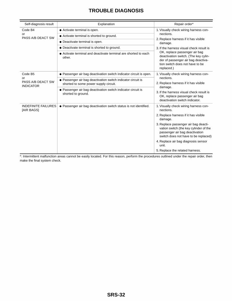
*: Intermittent malfunction areas cannot be easily located. For this reason, perform the procedures outlined under the repair order, thenmake the final system check.
Code B4orPASS A/B DEACT SW
● Activate terminal is open. 1. Visually check wiring harness con-nections.
2. Replace harness if it has visible damage.
3. If the harness visual check result is OK, replace passenger air bag deactivation switch. (The key cylin-der of passenger air bag deactiva-tion switch does not have to be replaced.)
● Activate terminal is shorted to ground.
● Deactivate terminal is open.
● Deactivate terminal is shorted to ground.
● Activate terminal and deactivate terminal are shorted to each other.
Code B5orPASS A/B DEACT SW INDICATOR
● Passenger air bag deactivation switch indicator circuit is open. 1. Visually check wiring harness con-nections.
2. Replace harness if it has visible damage.
3. If the harness visual check result is OK, replace passenger air bag deactivation switch indicator.
● Passenger air bag deactivation switch indicator circuit is shorted to some power supply circuit.
● Passenger air bag deactivation switch indicator circuit is shorted to ground.
INDEFINITE FAILURES[AIR BAGS]
● Passenger air bag deactivation switch status is not identified. 1. Visually check wiring harness con-nections.
2. Replace harness if it has visible damage.
3. Replace passenger air bag deacti-vation switch (the key cylinder of the passenger air bag deactivation switch does not have to be replaced)
4. Replace air bag diagnosis sensor unit.
5. Replace the related harness.
Self-diagnosis result Explanation Repair order*
TROUBLE DIAGNOSIS
SRS-33
C
D
E
F
G
I
J
K
L
M
A
B
SRS
Trouble Diagnoses without CONSULT-II EHS000H1
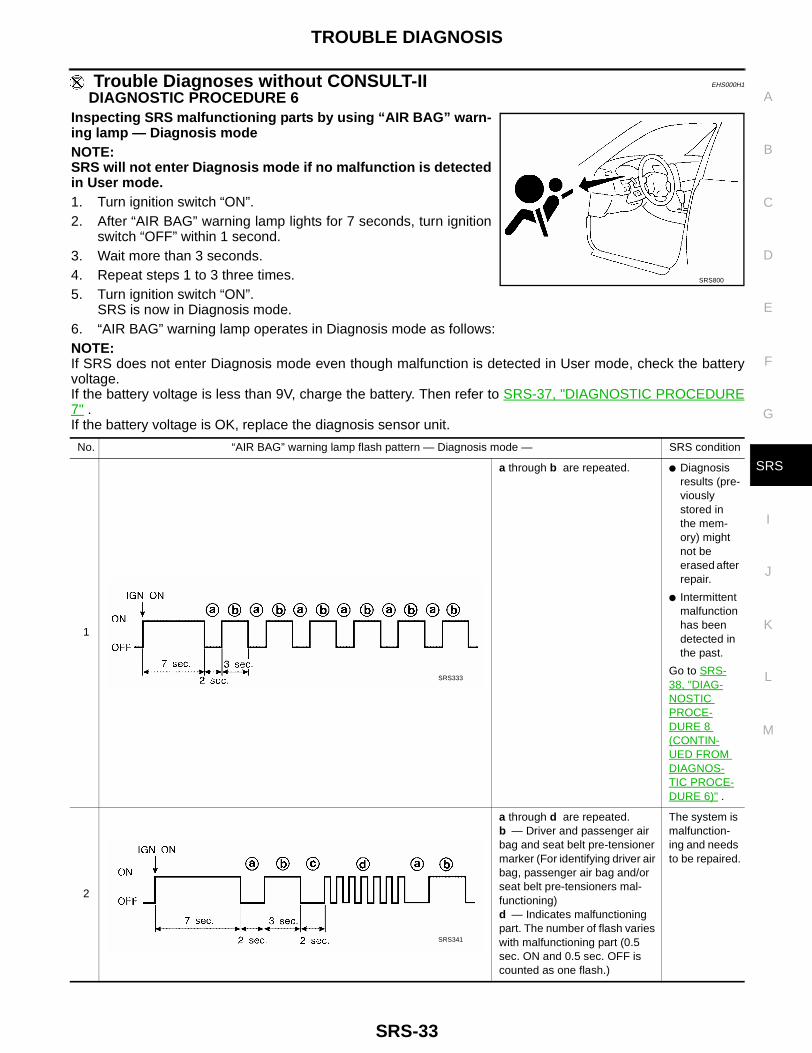
DIAGNOSTIC PROCEDURE 6Inspecting SRS malfunctioning parts by using “AIR BAG” warn-ing lamp — Diagnosis modeNOTE:SRS will not enter Diagnosis mode if no malfunction is detectedin User mode.1. Turn ignition switch “ON”.2. After “AIR BAG” warning lamp lights for 7 seconds, turn ignition
switch “OFF” within 1 second.3. Wait more than 3 seconds.4. Repeat steps 1 to 3 three times.5. Turn ignition switch “ON”.
SRS is now in Diagnosis mode.6. “AIR BAG” warning lamp operates in Diagnosis mode as follows:NOTE:If SRS does not enter Diagnosis mode even though malfunction is detected in User mode, check the batteryvoltage.If the battery voltage is less than 9V, charge the battery. Then refer to SRS-37, "DIAGNOSTIC PROCEDURE7" .If the battery voltage is OK, replace the diagnosis sensor unit.
SRS800
No. “AIR BAG” warning lamp flash pattern — Diagnosis mode — SRS condition
1
a through b are repeated. ● Diagnosis results (pre-viously stored in the mem-ory) might not be erased after repair.
● Intermittent malfunction has been detected in the past.
Go to SRS-38, "DIAG-NOSTIC PROCE-DURE 8 (CONTIN-UED FROM DIAGNOS-TIC PROCE-DURE 6)" .
2
a through d are repeated.b — Driver and passenger air bag and seat belt pre-tensioner marker (For identifying driver air bag, passenger air bag and/or seat belt pre-tensioners mal-functioning)d — Indicates malfunctioning part. The number of flash varies with malfunctioning part (0.5 sec. ON and 0.5 sec. OFF is counted as one flash.)
The system is malfunction-ing and needs to be repaired.
SRS333
SRS341

SRS-34
TROUBLE DIAGNOSIS
7. Malfunctioning part is indicated by the number of flashes (part d ). Compare the number of flashes to “AirBag Warning Lamp Flash Code Chart”. Refer to SRS-35, "Air Bag Warning Lamp Flash Code Chart (Diag-nosis Mode)" , and locate malfunctioning part.
8. Turn ignition switch “OFF”, and disconnect both battery cables.9. Repair the system as outlined by the “Repair order” in “Warning Lamp Flash Code Chart” that corre-
sponds to the flash code. For replacement procedure of component parts, refer to the applicable Removaland Installation procedure.
10. After repairing the system, refer to SRS-37, "DIAGNOSTIC PROCEDURE 7" .
TROUBLE DIAGNOSIS
SRS-35
C
D
E
F
G
I
J
K
L
M
A
B
SRS
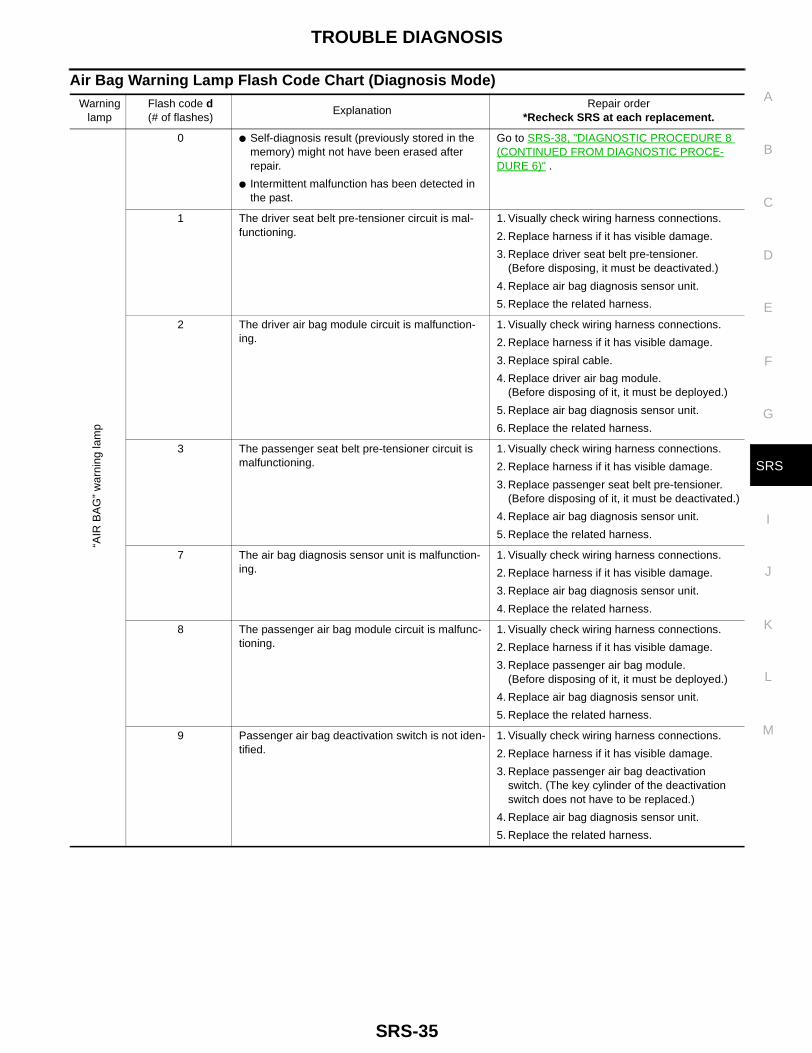
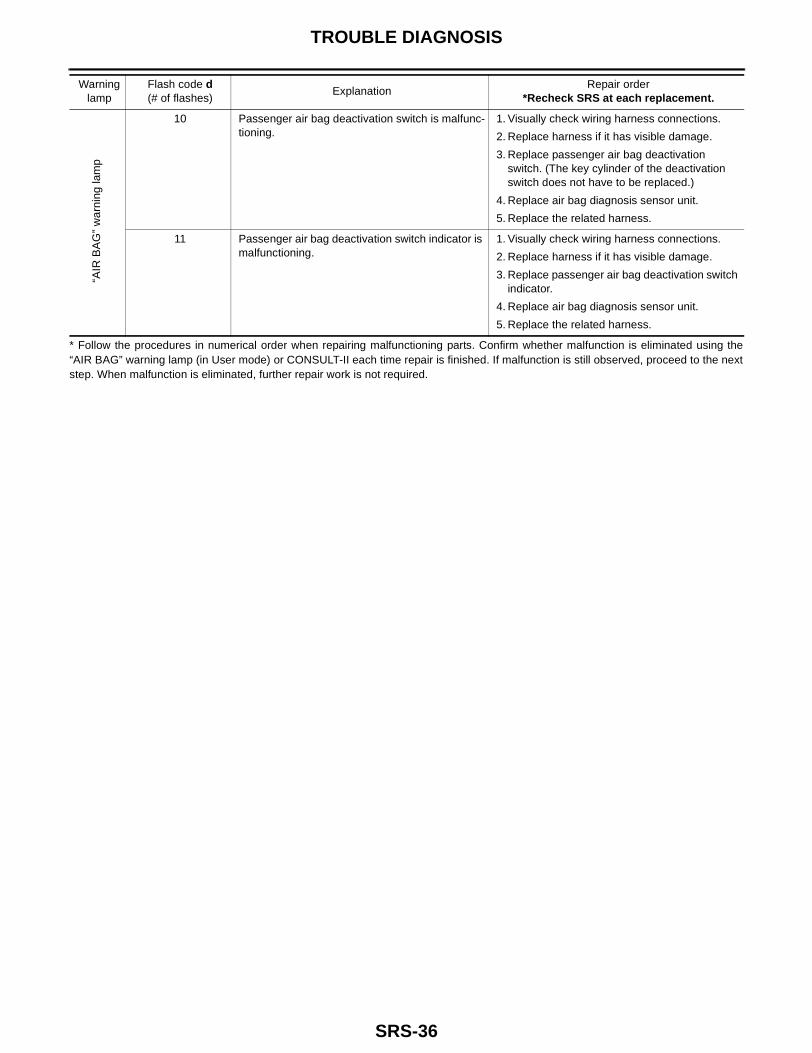
Air Bag Warning Lamp Flash Code Chart (Diagnosis Mode)Warning
lampFlash code d(# of flashes)
ExplanationRepair order
*Recheck SRS at each replacement.
“AIR
BA
G”
war
ning
lam
p
0 ● Self-diagnosis result (previously stored in the memory) might not have been erased after repair.
● Intermittent malfunction has been detected in the past.
Go to SRS-38, "DIAGNOSTIC PROCEDURE 8 (CONTINUED FROM DIAGNOSTIC PROCE-DURE 6)" .
1 The driver seat belt pre-tensioner circuit is mal-functioning.
1. Visually check wiring harness connections.
2. Replace harness if it has visible damage.
3. Replace driver seat belt pre-tensioner.(Before disposing, it must be deactivated.)
4. Replace air bag diagnosis sensor unit.
5. Replace the related harness.
2 The driver air bag module circuit is malfunction-ing.
1. Visually check wiring harness connections.
2. Replace harness if it has visible damage.
3. Replace spiral cable.
4. Replace driver air bag module.(Before disposing of it, it must be deployed.)
5. Replace air bag diagnosis sensor unit.
6. Replace the related harness.
3 The passenger seat belt pre-tensioner circuit is malfunctioning.
1. Visually check wiring harness connections.
2. Replace harness if it has visible damage.
3. Replace passenger seat belt pre-tensioner.(Before disposing of it, it must be deactivated.)
4. Replace air bag diagnosis sensor unit.
5. Replace the related harness.
7 The air bag diagnosis sensor unit is malfunction-ing.
1. Visually check wiring harness connections.
2. Replace harness if it has visible damage.
3. Replace air bag diagnosis sensor unit.
4. Replace the related harness.
8 The passenger air bag module circuit is malfunc-tioning.
1. Visually check wiring harness connections.
2. Replace harness if it has visible damage.
3. Replace passenger air bag module.(Before disposing of it, it must be deployed.)
4. Replace air bag diagnosis sensor unit.
5. Replace the related harness.
9 Passenger air bag deactivation switch is not iden-tified.
1. Visually check wiring harness connections.
2. Replace harness if it has visible damage.
3. Replace passenger air bag deactivation switch. (The key cylinder of the deactivation switch does not have to be replaced.)
4. Replace air bag diagnosis sensor unit.
5. Replace the related harness.
SRS-36
TROUBLE DIAGNOSIS
* Follow the procedures in numerical order when repairing malfunctioning parts. Confirm whether malfunction is eliminated using the“AIR BAG” warning lamp (in User mode) or CONSULT-II each time repair is finished. If malfunction is still observed, proceed to the nextstep. When malfunction is eliminated, further repair work is not required.
“AIR
BA
G”
war
ning
lam
p
10 Passenger air bag deactivation switch is malfunc-tioning.
1. Visually check wiring harness connections.
2. Replace harness if it has visible damage.
3. Replace passenger air bag deactivation switch. (The key cylinder of the deactivation switch does not have to be replaced.)
4. Replace air bag diagnosis sensor unit.
5. Replace the related harness.
11 Passenger air bag deactivation switch indicator is malfunctioning.
1. Visually check wiring harness connections.
2. Replace harness if it has visible damage.
3. Replace passenger air bag deactivation switch indicator.
4. Replace air bag diagnosis sensor unit.
5. Replace the related harness.
Warning lamp
Flash code d(# of flashes)
ExplanationRepair order
*Recheck SRS at each replacement.
TROUBLE DIAGNOSIS
SRS-37
C
D
E
F
G
I
J
K
L
M
A
B
SRS
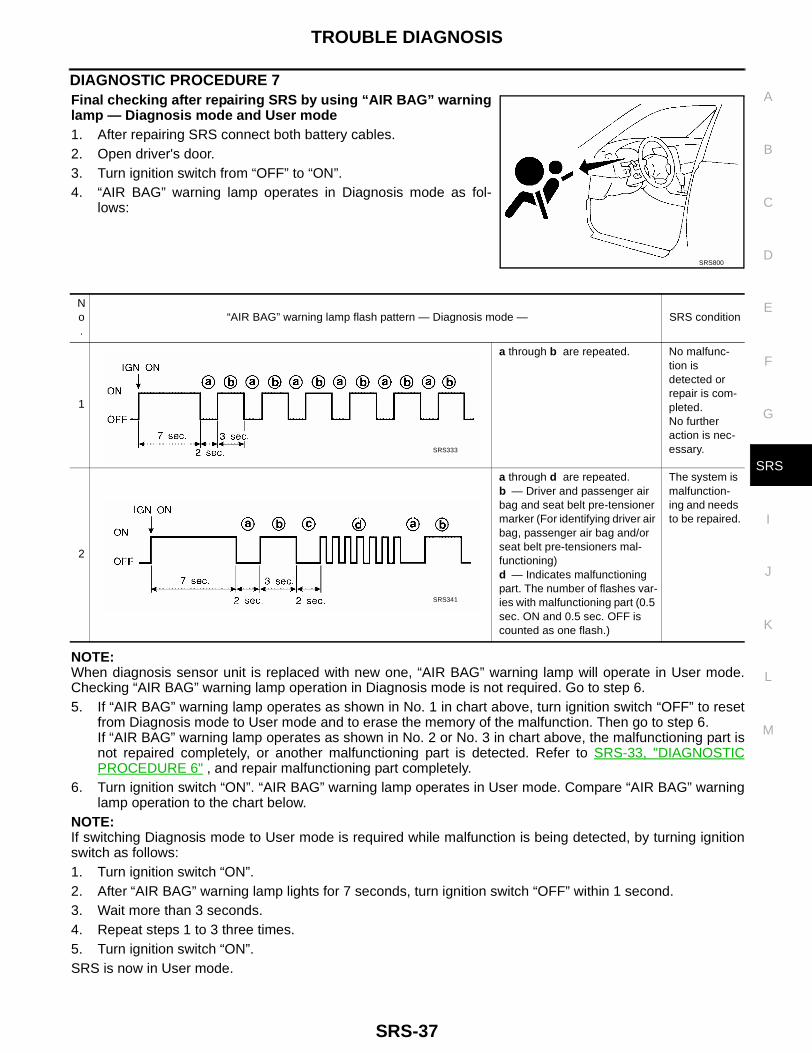
DIAGNOSTIC PROCEDURE 7Final checking after repairing SRS by using “AIR BAG” warninglamp — Diagnosis mode and User mode1. After repairing SRS connect both battery cables.2. Open driver's door.3. Turn ignition switch from “OFF” to “ON”.4. “AIR BAG” warning lamp operates in Diagnosis mode as fol-
lows:
NOTE:When diagnosis sensor unit is replaced with new one, “AIR BAG” warning lamp will operate in User mode.Checking “AIR BAG” warning lamp operation in Diagnosis mode is not required. Go to step 6.5. If “AIR BAG” warning lamp operates as shown in No. 1 in chart above, turn ignition switch “OFF” to reset
from Diagnosis mode to User mode and to erase the memory of the malfunction. Then go to step 6.If “AIR BAG” warning lamp operates as shown in No. 2 or No. 3 in chart above, the malfunctioning part isnot repaired completely, or another malfunctioning part is detected. Refer to SRS-33, "DIAGNOSTICPROCEDURE 6" , and repair malfunctioning part completely.
6. Turn ignition switch “ON”. “AIR BAG” warning lamp operates in User mode. Compare “AIR BAG” warninglamp operation to the chart below.
NOTE:If switching Diagnosis mode to User mode is required while malfunction is being detected, by turning ignitionswitch as follows:1. Turn ignition switch “ON”.2. After “AIR BAG” warning lamp lights for 7 seconds, turn ignition switch “OFF” within 1 second.3. Wait more than 3 seconds.4. Repeat steps 1 to 3 three times.5. Turn ignition switch “ON”.SRS is now in User mode.
SRS800
No.
“AIR BAG” warning lamp flash pattern — Diagnosis mode — SRS condition
1
a through b are repeated. No malfunc-tion is detected or repair is com-pleted.No further action is nec-essary.
2
a through d are repeated.b — Driver and passenger air bag and seat belt pre-tensioner marker (For identifying driver air bag, passenger air bag and/or seat belt pre-tensioners mal-functioning)d — Indicates malfunctioning part. The number of flashes var-ies with malfunctioning part (0.5 sec. ON and 0.5 sec. OFF is counted as one flash.)
The system is malfunction-ing and needs to be repaired.
SRS333
SRS341

SRS-38
TROUBLE DIAGNOSIS
DIAGNOSTIC PROCEDURE 8 (CONTINUED FROM DIAGNOSTIC PROCEDURE 6)Inspecting SRS malfunction record
1. CHECK FOR PROBLEM CODE THAT MIGHT NOT HAVE BEEN ERASED AFTER PREVIOUS REPAIR
Is it the first time for maintenance of SRS?Yes or NoYes >> Go to SRS-28, "DIAGNOSTIC PROCEDURE 5" . (Further inspection cannot be performed with-
out CONSULT-II.)No >> Self-diagnosis result (previously stored in the memory) might not have been erased after repair.
Go to SRS-37, "DIAGNOSTIC PROCEDURE 7" step 5.
“AIR BAG” warning lamp operation — User mode — SRS condition Reference item
No malfunction is detected.No further action is neces-sary. —
The system is malfunc-tioning and needs to be repaired as indicated.
Go to SRS-33, "DIAG-NOSTIC PROCEDURE 6" .
Air bag is deployed.Seat belt pre-tensioner is deployed.
Go to SRS-60, "Collision Diagnosis" .
Air bag fuse, diagnosis sensor unit or harness is malfunctioning and needs to be repaired.
Go to SRS-39, "DIAG-NOSTIC PROCEDURE 9" .
One of the following has occurred and needs to be repaired.
● Meter fuse is blown.
● “AIR BAG” warning lamp circuit has open or short.
● Diagnosis sensor unit is malfunctioning.
Go to SRS-40, "DIAG-NOSTIC PROCEDURE 10" .

TROUBLE DIAGNOSIS
SRS-39
C
D
E
F
G
I
J
K
L
M
A
B
SRS
Trouble Diagnoses: “AIR BAG” Warning Lamp Does Not Turn Off EHS000H2
DIAGNOSTIC PROCEDURE 9
1. CHECK FOR DEPLOYMENT OF AIR BAG MODULE
Is air bag module deployed?Yes or NoYes >> Refer to SRS-60, "Collision Diagnosis" .No >> GO TO 2.
2. CHECK AIR BAG FUSE
Is air bag fuse OK?OK or NGOK >> GO TO 4.NG >> GO TO 3.
3. CHECK AIR BAG FUSE AGAIN
Replace air bag fuse and turn ignition switch ON.Does air bag fuse blow again?Yes >> Repair main harness.No >> INSPECTION END
4. CHECK AIR BAG DIAGNOSIS SENSOR UNIT
1. Turn ignition switch OFF.2. Connect CONSULT-II.3. Turn ignition switch ON.4. Touch “START” on CONSULT-II screen.– Is “AIRBAG” displayed on CONSULT-II?Yes or NoYes >> GO TO 5.No >> Visually check wiring harness connection of air bag
diagnosis sensor unit. If harness connection checkresult is OK, replace air bag diagnosis sensor unit.
5. CHECK HARNESS CONNECTION
Are harness connections between “AIR BAG” warning lamp and air bag diagnosis sensor unit OK?OK or NGOK >> Replace air bag diagnosis sensor unit. Refer to SRS-41, "Removal and Installation"NG >> Connect combination meter, air bag diagnosis sensor unit and inline harness connectors properly.
If “AIR BAG” warning lamp still does not go off, repair main harness.
ARS349
SRS697
SRS-40
TROUBLE DIAGNOSIS
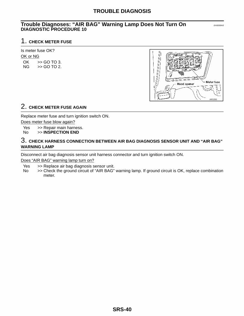
Trouble Diagnoses: “AIR BAG” Warning Lamp Does Not Turn On EHS000H3
DIAGNOSTIC PROCEDURE 10
1. CHECK METER FUSE
Is meter fuse OK?OK or NGOK >> GO TO 3.NG >> GO TO 2.
2. CHECK METER FUSE AGAIN
Replace meter fuse and turn ignition switch ON.Does meter fuse blow again?Yes >> Repair main harness.No >> INSPECTION END
3. CHECK HARNESS CONNECTION BETWEEN AIR BAG DIAGNOSIS SENSOR UNIT AND “AIR BAG” WARNING LAMP
Disconnect air bag diagnosis sensor unit harness connector and turn ignition switch ON.Does “AIR BAG” warning lamp turn on?Yes >> Replace air bag diagnosis sensor unit.No >> Check the ground circuit of “AIR BAG” warning lamp. If ground circuit is OK, replace combination
meter.
ARS350
DIAGNOSIS SENSOR UNIT
SRS-41
C
D
E
F
G
I
J
K
L
M
A
B
SRS
DIAGNOSIS SENSOR UNIT PFP:28556
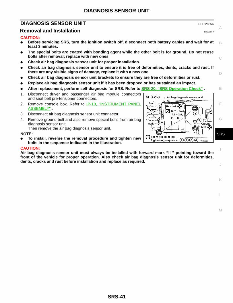
Removal and Installation EHS000G4
CAUTION:● Before servicing SRS, turn the ignition switch off, disconnect both battery cables and wait for at
least 3 minutes.● The special bolts are coated with bonding agent while the other bolt is for ground. Do not reuse
bolts after removal; replace with new ones.● Check air bag diagnosis sensor unit for proper installation.● Check air bag diagnosis sensor unit to ensure it is free of deformities, dents, cracks and rust. If
there are any visible signs of damage, replace it with a new one.● Check air bag diagnosis sensor unit brackets to ensure they are free of deformities or rust.● Replace air bag diagnosis sensor unit if it has been dropped or has sustained an impact.● After replacement, perform self-diagnosis for SRS. Refer to SRS-20, "SRS Operation Check" .1. Disconnect driver and passenger air bag module connectors
and seat belt pre-tensioner connectors.2. Remove console box. Refer to IP-10, "INSTRUMENT PANEL
ASSEMBLY" .3. Disconnect air bag diagnosis sensor unit connector.4. Remove ground bolt and also remove special bolts from air bag
diagnosis sensor unit.Then remove the air bag diagnosis sensor unit.
NOTE:● To install, reverse the removal procedure and tighten new
bolts in the sequence indicated in the illustration.CAUTION:Air bag diagnosis sensor unit must always be installed with forward mark “⇐ ” pointing toward thefront of the vehicle for proper operation. Also check air bag diagnosis sensor unit for deformities,dents, cracks and rust before installation and replace as required.
WRS228
SRS-42
CRASH ZONE SENSOR
CRASH ZONE SENSOR PFP:98531
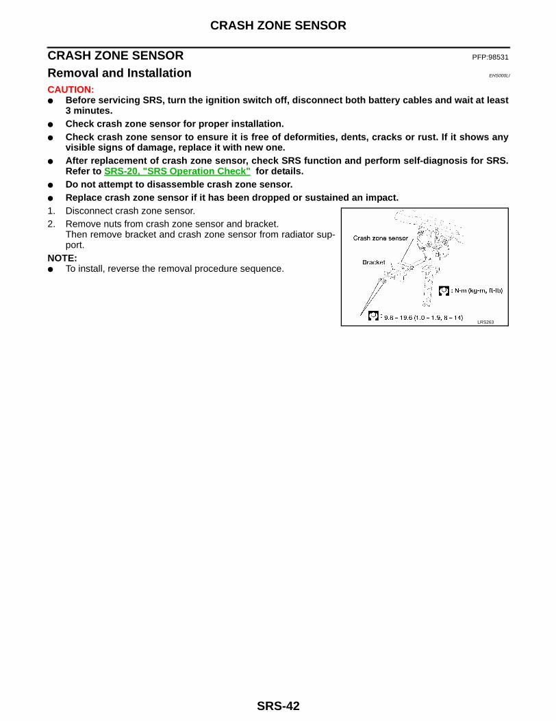
Removal and Installation EHS000LI
CAUTION:● Before servicing SRS, turn the ignition switch off, disconnect both battery cables and wait at least
3 minutes.● Check crash zone sensor for proper installation.● Check crash zone sensor to ensure it is free of deformities, dents, cracks or rust. If it shows any
visible signs of damage, replace it with new one.● After replacement of crash zone sensor, check SRS function and perform self-diagnosis for SRS.
Refer to SRS-20, "SRS Operation Check" for details.● Do not attempt to disassemble crash zone sensor.● Replace crash zone sensor if it has been dropped or sustained an impact.1. Disconnect crash zone sensor.2. Remove nuts from crash zone sensor and bracket.
Then remove bracket and crash zone sensor from radiator sup-port.
NOTE:● To install, reverse the removal procedure sequence.
LRS263

FRONT SEAT BELT PRE-TENSIONER
SRS-43
C
D
E
F
G
I
J
K
L
M
A
B
SRS
FRONT SEAT BELT PRE-TENSIONER PFP:86884
Removal and Installation EHS000G5
For removal and instllation of seat belt pre-tensioner, refer to SB-4, "FRONT SEAT BELT" .
SRS-44
DRIVER AIR BAG MODULE AND SPIRAL CABLE
DRIVER AIR BAG MODULE AND SPIRAL CABLE PFP:K8510
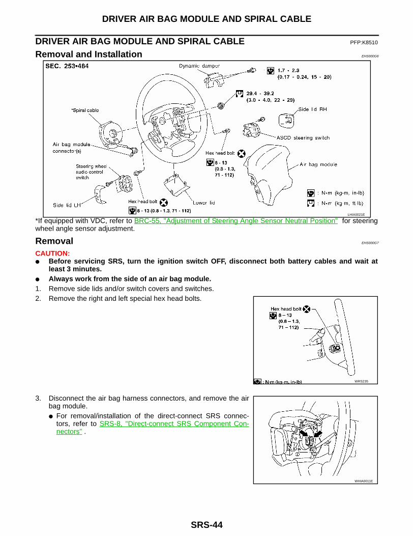
Removal and Installation EHS000G6
*If equipped with VDC, refer to BRC-55, "Adjustment of Steering Angle Sensor Neutral Position" for steeringwheel angle sensor adjustment.
Removal EHS000G7
CAUTION:● Before servicing SRS, turn the ignition switch OFF, disconnect both battery cables and wait at
least 3 minutes.● Always work from the side of an air bag module.1. Remove side lids and/or switch covers and switches. 2. Remove the right and left special hex head bolts.
3. Disconnect the air bag harness connectors, and remove the airbag module.● For removal/installation of the direct-connect SRS connec-
tors, refer to SRS-8, "Direct-connect SRS Component Con-nectors" .
LHIA0021E
WRS235
WHIA0011E

DRIVER AIR BAG MODULE AND SPIRAL CABLE
SRS-45
C
D
E
F
G
I
J
K
L
M
A
B
SRS
CAUTION:● Always place air bag module with pad side facing upward.● Do not attempt to disassemble air bag module.● The special bolts are coated with bonding agent. Do not use
old bolts after removal; replace with new ones.● Do not insert any foreign objects (screwdriver, etc.) into air
bag module connector.
● Do not drop or impact air bag module. If any portion isdeformed or cracked, replace the module.
● Do not expose the air bag module to temperatures exceed-ing 90°C (194°F).
● Do not allow oil, grease or water to come in contact with theair bag module.
4. Set steering wheel in the neutral position.5. Disconnect horn connector from steering wheel (floating horn
bracket).6. Release the spiral cable connectors from the steering wheel by
sliding off the connector brackets and remove nut.7. Using steering wheel puller, remove steering wheel. Be careful
not to over-tighten puller bolt on steering wheel.CAUTION:● Do not tap or bump the steering wheel.
8. Remove steering column covers, instrument panel lower LH andknee protector.
9. Disconnect spiral cable connector from air bag harness.10. Remove the four spiral cable retaining screws. Remove the spi-
ral cable.CAUTION:● Do not attempt to disassemble spiral cable.● Do not apply lubricant to the spiral cable.
ARS379
SBF814E
SST480C
WRS237

SRS-46
DRIVER AIR BAG MODULE AND SPIRAL CABLE
Installation EHS000G8
1. Set the front wheels in the straight-ahead position.2. Align the turn signal cancel tab with the notch of the combination
switch as shown.
3. Rotate the spiral cable fully clockwise until tight.4. Rotate the spiral cable counterclockwise approximately 2.25
turns and align white pin with arrow on housing.● When the spiral cable is centered, white pin is aligned
with arrow on housing and yellow wheel shows in win-dow.
CAUTION:● The spiral cable may snap during steering operation if
the spiral cable is installed in an improper position.● Also, with the steering linkage disconnected, the cable
may snap by turning the steering wheel beyond the lim-ited number of turns. The spiral cable can be turnedcounterclockwise approximately 2.25 turns. Always per-form SRS self-diagnosis after installing the air bag mod-ule. Refer to SRS-20, "SRS Operation Check" .
5. Connect spiral cable to air bag harness and tighten screws.Install steering column covers.
ARS152
SRS276

DRIVER AIR BAG MODULE AND SPIRAL CABLE
SRS-47
C
D
E
F
G
I
J
K
L
M
A
B
SRS
6. Install steering wheel, setting spiral cable pin guide, and pull spi-ral cable connectors through.
7. Install dynamic damper.8. Tighten steering wheel nut.
9. Connect spiral cable connectors to floating horn bracket andattach to any switch connector brackets.
10. Attach spiral cable air bag connector to driver air bag module.● For removal/installation of the direct-connect SRS connec-
tors, refer to SRS-8, "Direct-connect SRS Component Connectors" .
11. Position driver air bag module and install two new hex headbolts.
12. Install any switches.13. Install all lids.14. Connect both battery cables.
● If equipped with VDC, refer to BRC-55, "Adjustment of Steer-ing Angle Sensor Neutral Position" for steering wheel anglesensor adjustment.
15. Conduct self-diagnosis to ensure entire SRS operates properly.(Use CONSULT-II or “AIR BAG” warning lamp check.) Turn thesteering wheel fully to the right and left to check that the spiralcable is set in the neutral position.
16. If “AIR BAG” warning lamp blinks (in User mode), it shows the spiral cable may be snapped due to itsimproper position. Perform Self-diagnosis again. (Use CONSULT-II or “AIR BAG” warning lamp check.) Ifa malfunction is detected, replace the spiral cable with a new one.
NOTE:● After replacement, perform self-diagnosis for SRS. Refer to SRS-20, "SRS Operation Check" .
: 29 - 39 N·m (3.0 - 4.0 kg-m, 22 - 29 ft-lb)
SBF818E
WRS235
SRS-48
FRONT PASSENGER AIR BAG MODULE
FRONT PASSENGER AIR BAG MODULE PFP:K8515
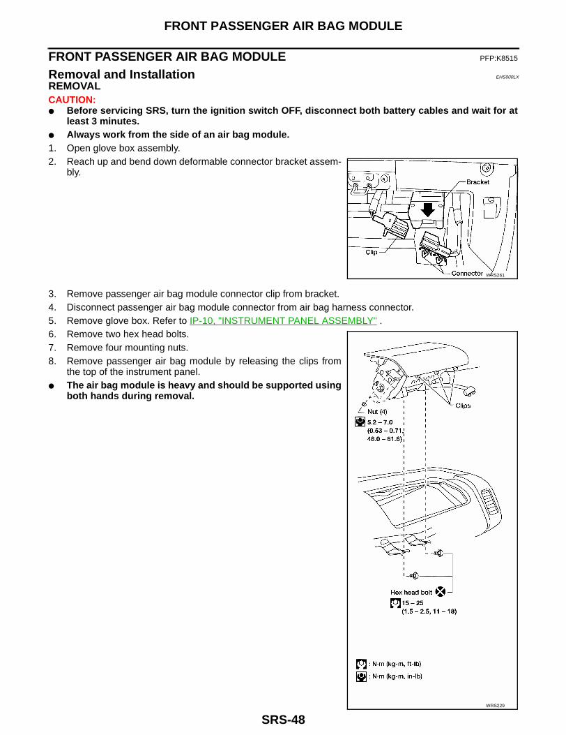
Removal and Installation EHS000LX
REMOVALCAUTION:● Before servicing SRS, turn the ignition switch OFF, disconnect both battery cables and wait for at
least 3 minutes.● Always work from the side of an air bag module.1. Open glove box assembly.2. Reach up and bend down deformable connector bracket assem-
bly.
3. Remove passenger air bag module connector clip from bracket.4. Disconnect passenger air bag module connector from air bag harness connector.5. Remove glove box. Refer to IP-10, "INSTRUMENT PANEL ASSEMBLY" .6. Remove two hex head bolts.7. Remove four mounting nuts.8. Remove passenger air bag module by releasing the clips from
the top of the instrument panel.● The air bag module is heavy and should be supported using
both hands during removal.
WRS261
WRS229
FRONT PASSENGER AIR BAG MODULE
SRS-49
C
D
E
F
G
I
J
K
L
M
A
B
SRS
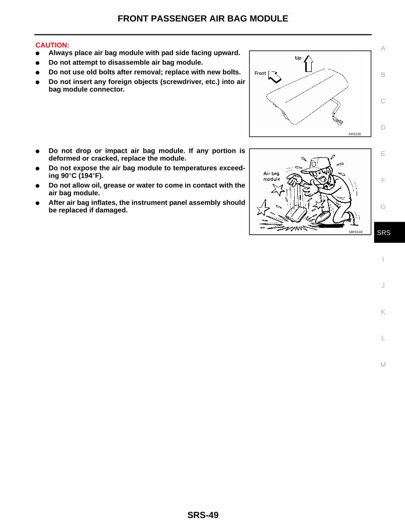
CAUTION:● Always place air bag module with pad side facing upward.● Do not attempt to disassemble air bag module.● Do not use old bolts after removal; replace with new bolts.● Do not insert any foreign objects (screwdriver, etc.) into air
bag module connector.
● Do not drop or impact air bag module. If any portion isdeformed or cracked, replace the module.
● Do not expose the air bag module to temperatures exceed-ing 90°C (194°F).
● Do not allow oil, grease or water to come in contact with theair bag module.
● After air bag inflates, the instrument panel assembly shouldbe replaced if damaged.
ARS330
SBF814E

SRS-50
FRONT PASSENGER AIR BAG MODULE
INSTALLATIONCAUTION:● Always work from the side of an air bag module.1. Install passenger air bag module in instrument panel.
1. Insert front edge of passenger air bag module first to easeinstallation.
– Ensure harness is not caught between passenger air bagmodule and support bracket.
2. Install four mounting nuts.3. Install two new hex head bolts.
2. Install glove box. Refer to IP-10, "INSTRUMENT PANELASSEMBLY" .
3. Connect air bag harness connector to passenger air bag moduleharness connector.
4. Attach passenger air bag module connector clip to bracket(Bracket in down position).
5. Bend bracket up clear of glove box and close glove box.6. Connect both battery cables.7. Conduct self-diagnosis to ensure entire SRS operates properly
(Use CONSULT-II or “AIR BAG” warning lamp check).NOTE:● After replacement, perform self-diagnosis for SRS. Refer to
SRS-20, "SRS Operation Check" .
WRS229
WRS261

PASSENGER AIR BAG DEACTIVATION SWITCH
SRS-51
C
D
E
F
G
I
J
K
L
M
A
B
SRS
PASSENGER AIR BAG DEACTIVATION SWITCH PFP:25585
Removal EHS000GB
● Before servicing SRS, turn the ignition switch OFF, disconnect both battery cables and wait for atleast 3 minutes.
1. Remove cluster lid-C. Refer to IP-10, "Removal and Installation" .2. Disengage the two locking tabs from the passenger air bag deactivation switch lock cylinder and remove
passenger air bag deactivation switch.
Installation EHS000GC
CAUTION:Passenger air bag deactivation switch is keyed for proper installation. Improper positioning of theswitch will result in damage to the switch.NOTE:● Be sure that the passenger air bag deactivation switch and lock cylinder is connected and in the
same position as during removal for proper engagement.● To install, reverse removal procedure.● After replacement, perform self-diagnosis for SRS. Refer to SRS-20, "SRS Operation Check" .
LRS247
SRS-52
PASSENGER AIR BAG DEACTIVATION SWITCH LOCK CYLINDER
PASSENGER AIR BAG DEACTIVATION SWITCH LOCK CYLINDER PFP:25585
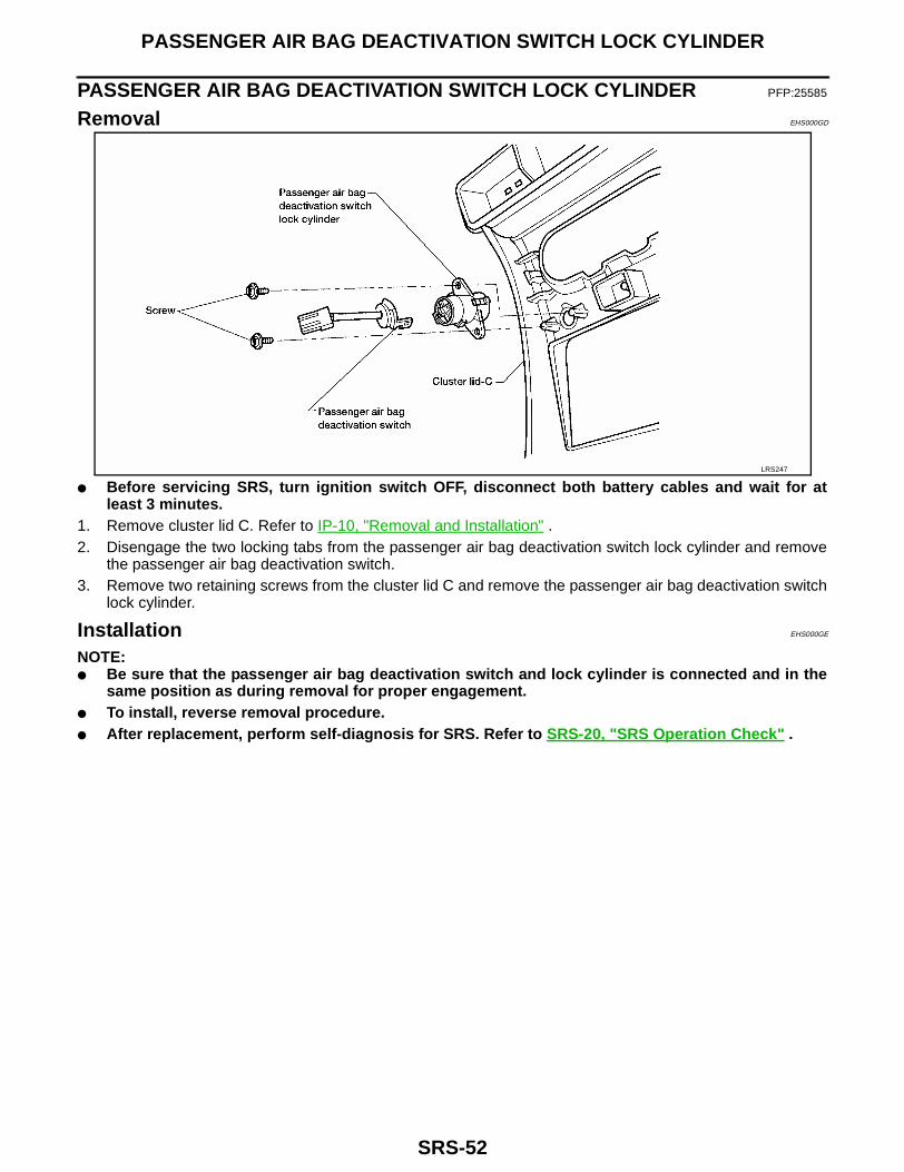
Removal EHS000GD
● Before servicing SRS, turn ignition switch OFF, disconnect both battery cables and wait for atleast 3 minutes.
1. Remove cluster lid C. Refer to IP-10, "Removal and Installation" .2. Disengage the two locking tabs from the passenger air bag deactivation switch lock cylinder and remove
the passenger air bag deactivation switch.3. Remove two retaining screws from the cluster lid C and remove the passenger air bag deactivation switch
lock cylinder.
Installation EHS000GE
NOTE:● Be sure that the passenger air bag deactivation switch and lock cylinder is connected and in the
same position as during removal for proper engagement.● To install, reverse removal procedure.● After replacement, perform self-diagnosis for SRS. Refer to SRS-20, "SRS Operation Check" .
LRS247
PASSENGER AIR BAG DEACTIVATION SWITCH INDICATOR
SRS-53
C
D
E
F
G
I
J
K
L
M
A
B
SRS
PASSENGER AIR BAG DEACTIVATION SWITCH INDICATOR PFP:25585
Removal EHS000GF
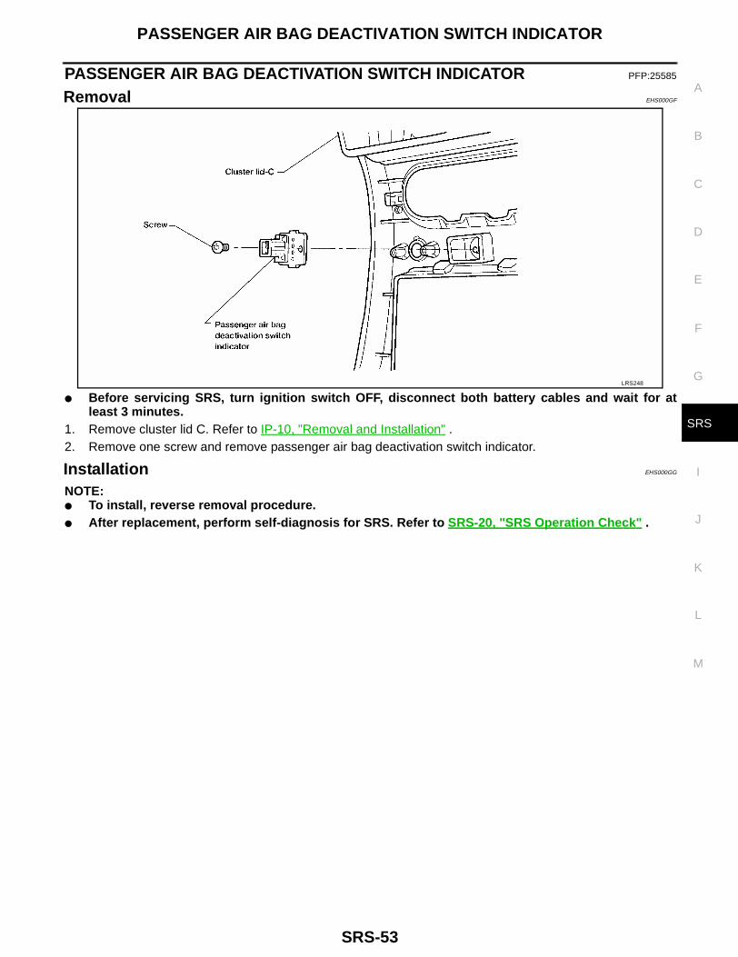
● Before servicing SRS, turn ignition switch OFF, disconnect both battery cables and wait for atleast 3 minutes.
1. Remove cluster lid C. Refer to IP-10, "Removal and Installation" .2. Remove one screw and remove passenger air bag deactivation switch indicator.
Installation EHS000GG
NOTE:● To install, reverse removal procedure.● After replacement, perform self-diagnosis for SRS. Refer to SRS-20, "SRS Operation Check" .
LRS248
SRS-54
DISPOSAL OF AIR BAG MODULE AND SEAT BELT PRE-TENSIONER
DISPOSAL OF AIR BAG MODULE AND SEAT BELT PRE-TENSIONER PFP:00014
Disposal of Air Bag Module and Seat Belt Pre-tensioner EHS000H4
● Before disposing of air bag modules and seat belt pre-tensioners, or vehicles equipped with such sys-tems, deploy the systems. If such systems have already been deployed due to an accident, dispose of asindicated in SRS-54, "Disposal of Air Bag Module and Seat Belt Pre-tensioner" .
● When deploying air bag module or seat belt pre-tensioner, always use the Special Service Tool; Deploy-ment tool KV99106400 (Kent-Moore No. J38381).
● When deploying air bag module or seat belt pre-tensioner, stand at least 5 m (16 ft) away from the deploy-ment component.
● When deploying air bag module or seat belt pre-tensioner, a fairly loud noise is made, followed by smokebeing released. The smoke is not poisonous, however, be careful not to inhale smoke as it irritates thethroat and can cause choking.
● Only activate one air bag module or seat belt pre-tensioner at a time.● Due to heat, leave air bag module unattended for more than 30 minutes after deployment. Leave seat belt
pre-tensioner unattended for more than 10 minutes after deployment.● Be sure to wear gloves when handling a deployed air bag module or seat belt pre-tensioner.● Never apply water to a deployed air bag module or seat belt pre-tensioner.● Wash your hands clean after finishing work.● Place the vehicle outdoors with an open space of at least 6 m (20 ft) on all sides when deploying air bag
module or seat belt pre-tensioner while mounted in vehicle.● Use a voltmeter to make sure the vehicle battery is fully charged.● Do not dispose of the air bag module or seat belt pre-tensioner undeployed.
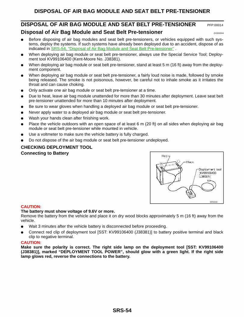
CHECKING DEPLOYMENT TOOLConnecting to Battery
CAUTION:The battery must show voltage of 9.6V or more.Remove the battery from the vehicle and place it on dry wood blocks approximately 5 m (16 ft) away from thevehicle.● Wait 3 minutes after the vehicle battery is disconnected before proceeding.● Connect red clip of deployment tool [SST: KV99106400 (J38381)] to battery positive terminal and black
clip to negative terminal.CAUTION:Make sure the polarity is correct. The right side lamp on the deployment tool [SST: KV99106400(J38381)], marked “DEPLOYMENT TOOL POWER”, should glow with a green light. If the right sidelamp glows red, reverse the connections to the battery.
SRS019

DISPOSAL OF AIR BAG MODULE AND SEAT BELT PRE-TENSIONER
SRS-55
C
D
E
F
G
I
J
K
L
M
A
B
SRS
Deployment Tool CheckPress the deployment tool [SST: KV99106400 (J38381)] switch tothe ON position. The left side lamp on the deployment tool [SST:KV99106400 (J38381)], marked “AIR BAG CONNECTOR VOLT-AGE”, should illuminate. If it does not illuminate, replace the tool.
Air Bag Deployment Tool Lamp Illumination Chart (Battery connected)
*: If this lamp glows red, the tool is connected to the battery incorrectly. Reverse the connections and make sure the lamp glows green.
DEPLOYMENT PROCEDURES FOR AIR BAG MODULE (OUTSIDE OF VEHICLE)Unless the vehicle is being scrapped, deploying the air bag modulesin the vehicle is not recommended. This may cause damage to thevehicle interior.Anchor air bag module bracket [KV99105300 (J41246)] in a visesecured to a firm foundation during deployment.
Deployment of Driver Air Bag Module (Outside of vehicle)1. Using wire, secure driver air bag module to air bag module
bracket [SST: KV99105300 (J41246)] at two places.CAUTION:If a gap exists between driver air bag module and air bagmodule bracket, use a piece of wood inserted in the gap tostabilize the air bag module.Use wire of at least 1 mm (0.04 in) diameter.
2. Firmly secure air bag module bracket [SST: KV99105300 (J41246)] with driver air bag module attached, ina vise.
SBF266H
Switch operationLeft side lamp, green*
“AIR BAG CONNECTOR VOLTAGE”
Right side lamp, green*“DEPLOYMENT TOOL
POWER”
OFF OFF ON
ON ON ON
ARS185
ARS186

SRS-56
DISPOSAL OF AIR BAG MODULE AND SEAT BELT PRE-TENSIONER
3. Connect deployment tool adapter [SST: KV99109000 (J44230)]:for 2-door models or [J38381-80-A]: for 4-door models todeployment tool [SST: KV99106400 (J38381)] and driver air bagmodule connector.
4. Connect red clip of deployment tool [SST: KV99106400(J38381)] to battery positive terminal and black clip to negativeterminal.
5. The right side lamp on the deployment tool [SST: KV99106400(J38381)], marked “DEPLOYMENT TOOL POWER”, shouldglow green, not red.
6. Press the button on the deployment tool [SST: KV99106400(J38381)]. The left side lamp on the deployment tool [SST:KV99106400 (J38381)], marked “AIR BAG CONNECTOR VOLTAGE”, will illuminate and the air bag mod-ule will deploy.
CAUTION:When deploying the air bag module, stand at least 5 m (16 ft) away from the air bag module.
Deployment of Passenger Air Bag Module (Outside of vehicle)1. Make an 8.5 mm (0.335 in) diameter hole in air bag module
bracket [SST: KV99105300 (J41246)] at the position shown.
2. Firmly secure air bag module bracket [SST: KV99105300(J41246)] in a vise.
3. Match the two holes in air bag module bracket [SST:KV99105300 (J41246)] (held in vise) and passenger air bagmodule and fix them with two bolts [M8 x 25 - 30 mm (0.98 - 1.18in)].
CAUTION:If a gap exists between passenger air bag module and air bagmodule bracket, use a piece of wood inserted in the gap to sta-bilize the air bag module.
WRS242
LRS169
ARS185
ARS234
DISPOSAL OF AIR BAG MODULE AND SEAT BELT PRE-TENSIONER
SRS-57
C
D
E
F
G
I
J
K
L
M
A
B
SRS
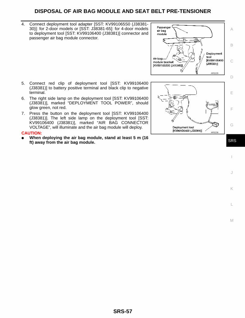
4. Connect deployment tool adapter [SST: KV991065S0 (J38381-30)]: for 2-door models or [SST: J38381-65]: for 4-door modelsto deployment tool [SST: KV99106400 (J38381)] connector andpassenger air bag module connector.
5. Connect red clip of deployment tool [SST: KV99106400(J38381)] to battery positive terminal and black clip to negativeterminal.
6. The right side lamp on the deployment tool [SST: KV99106400(J38381)], marked “DEPLOYMENT TOOL POWER”, shouldglow green, not red.
7. Press the button on the deployment tool [SST: KV99106400(J38381)]. The left side lamp on the deployment tool [SST:KV99106400 (J38381)], marked “AIR BAG CONNECTORVOLTAGE”, will illuminate and the air bag module will deploy.
CAUTION:● When deploying the air bag module, stand at least 5 m (16
ft) away from the air bag module.
ARS235
ARS236

SRS-58
DISPOSAL OF AIR BAG MODULE AND SEAT BELT PRE-TENSIONER
Deployment of Seat Belt Pre-tensioner (Outside of vehicle)1. Firmly anchor seat belt pre-tensioner in a vise, then cut webbing
off.
2. Connect deployment tool [SST: KV99106400 (J38381)] and deployment tool adapter [SST: J38381-80-A]connector to seat belt pre-tensioner.
3. Connect red clip of deployment tool [SST: KV99106400(J38381)] to battery positive terminal and black clip to negativeterminal.
4. The right side lamp on the deployment tool [SST: KV99106400(J38381)], marked “DEPLOYMENT TOOL POWER”, shouldglow green, not red.
5. Press the button on the deployment tool [SST: KV99106400(J38381)]. The left side lamp on the deployment tool [SST:KV99106400 (J38381)], marked “AIR BAG CONNECTORVOLTAGE”, will illuminate and the seat belt pre-tensioner willdeploy.
CAUTION:● When deploying the seat belt pre-tensioner, stand at least 5 m (16 ft) away from the seat belt pre-
tensioner.
LRS205
LRS206
DISPOSAL OF AIR BAG MODULE AND SEAT BELT PRE-TENSIONER
SRS-59
C
D
E
F
G
I
J
K
L
M
A
B
SRS
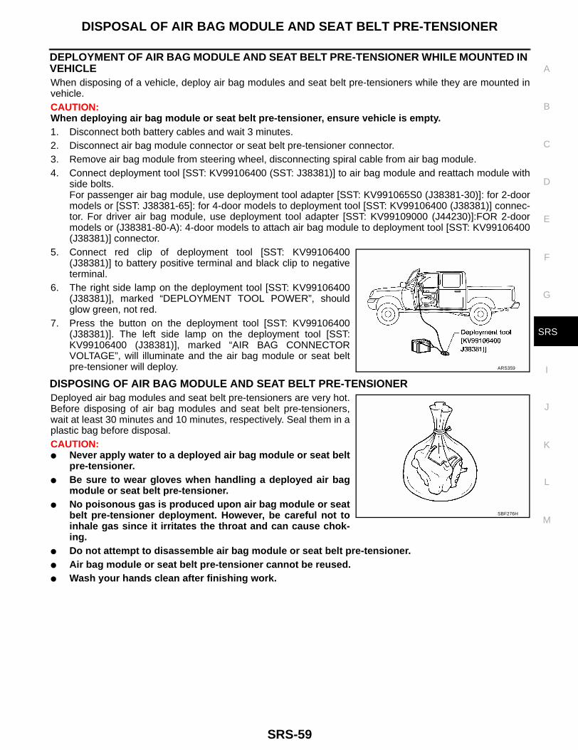
DEPLOYMENT OF AIR BAG MODULE AND SEAT BELT PRE-TENSIONER WHILE MOUNTED IN VEHICLEWhen disposing of a vehicle, deploy air bag modules and seat belt pre-tensioners while they are mounted invehicle.CAUTION:When deploying air bag module or seat belt pre-tensioner, ensure vehicle is empty.1. Disconnect both battery cables and wait 3 minutes.2. Disconnect air bag module connector or seat belt pre-tensioner connector.3. Remove air bag module from steering wheel, disconnecting spiral cable from air bag module.4. Connect deployment tool [SST: KV99106400 (SST: J38381)] to air bag module and reattach module with
side bolts.For passenger air bag module, use deployment tool adapter [SST: KV991065S0 (J38381-30)]: for 2-doormodels or [SST: J38381-65]: for 4-door models to deployment tool [SST: KV99106400 (J38381)] connec-tor. For driver air bag module, use deployment tool adapter [SST: KV99109000 (J44230)]:FOR 2-doormodels or (J38381-80-A): 4-door models to attach air bag module to deployment tool [SST: KV99106400(J38381)] connector.
5. Connect red clip of deployment tool [SST: KV99106400(J38381)] to battery positive terminal and black clip to negativeterminal.
6. The right side lamp on the deployment tool [SST: KV99106400(J38381)], marked “DEPLOYMENT TOOL POWER”, shouldglow green, not red.
7. Press the button on the deployment tool [SST: KV99106400(J38381)]. The left side lamp on the deployment tool [SST:KV99106400 (J38381)], marked “AIR BAG CONNECTORVOLTAGE”, will illuminate and the air bag module or seat beltpre-tensioner will deploy.
DISPOSING OF AIR BAG MODULE AND SEAT BELT PRE-TENSIONERDeployed air bag modules and seat belt pre-tensioners are very hot.Before disposing of air bag modules and seat belt pre-tensioners,wait at least 30 minutes and 10 minutes, respectively. Seal them in aplastic bag before disposal.CAUTION:● Never apply water to a deployed air bag module or seat belt
pre-tensioner.● Be sure to wear gloves when handling a deployed air bag
module or seat belt pre-tensioner.● No poisonous gas is produced upon air bag module or seat
belt pre-tensioner deployment. However, be careful not toinhale gas since it irritates the throat and can cause chok-ing.
● Do not attempt to disassemble air bag module or seat belt pre-tensioner.● Air bag module or seat belt pre-tensioner cannot be reused.● Wash your hands clean after finishing work.
ARS359
SBF276H

SRS-60
COLLISION DIAGNOSIS
COLLISION DIAGNOSIS PFP:00015
Collision Diagnosis EHS000H6
To repair the SRS, perform the following steps.When SRS is activated in a collision:1. Replace the diagnosis sensor unit.2. Remove the air bag modules and seat belt pre-tensioner assemblies.3. Check the SRS components using the table shown below:– Replace any SRS components showing visible signs of damage (dents, cracks and deformation).4. Install new air bag modules and seat belt pre-tensioner assemblies.5. Conduct self-diagnosis using CONSULT-II or “AIR BAG” warning lamp. Refer to SRS-20, "SRS Operation
Check" . Ensure entire SRS operates properly.When SRS is not activated in a collision:1. Check the SRS components using the table shown below:– Replace any SRS components showing visible signs of damage (dents, cracks and deformation).2. Conduct self-diagnosis using CONSULT-II or “AIR BAG” warning lamp. Refer to SRS-20, "SRS Operation
Check" . Ensure entire SRS operates properly.
SRS INSPECTIONPart SRS is activated SRS is NOT activated
Air bag module (driver and passen-ger)
REPLACEInstall with new bolts coated with bonding agent.
1. Remove air bag module. Check harness cover and connectors for damage, termi-nals for deformities, and harness for binding.
2.
– Install driver air bag module into the steering wheel to check fit and alignment with the wheel.
– Install passenger air bag module into the instrument panel to check fit with the instrument panel.
3. No damage found, reinstall with new bolts coated with bonding agent.
4. If damaged—REPLACE. Install air bag modules with new bolts coated with bond-ing agent. Air bag must be deployed before discarding.
Crash zone sensor (4-door models)
REPLACE the crash zone sensor and bracket with new nuts and bolts coated with bonding agent.
1. Remove the crash zone sensor. Check harness connectors for damage, terminals for deformities, and harness for binding.
2. Check for visible signs of damage (dents, cracks, deformation) of the crash zone sensor and bracket.
3. Install the crash zone sensor to check fit.
4. If no damage is found, reinstall the crash zone sensor with new nuts coated with bonding agent.
5. If damaged—REPLACE the crash zone sensor and bracket with new nuts and bolts coated with bonding agent.
Seat belt pre-ten-sioner assembly
REPLACEInstall seat belt pre-tensioner with new bolts.
1. Remove seat belt pre-tensioners.Check harness cover and connectors for damage, terminals for deformities, and harness for binding.
2. Check belts for damage and anchors for loose mounting.
3. Check retractor for smooth operation.
4. If no damage is found, reinstall seat belt pre-tensioner assembly.
5. If damaged—REPLACE. Install the seat belt pre-tensioners with new bolts coated with bonding agent. Seat belt pre-tensioners must be deployed before discarding.
Diagnosis sensor unit REPLACEInstall with new bolts coated with bonding agent.
1. Check case for dents, cracks or deformities.
2. Check connectors for damage, and terminals for deformities.
3. If no damage is found, reinstall with new bolts and ground bolt coated with bonding agent.
4. If damaged—REPLACE. Install diagnosis sensor unit with new bolts and ground bolt coated with bonding agent.
COLLISION DIAGNOSIS
SRS-61
C
D
E
F
G
I
J
K
L
M
A
B
SRS
Steering wheel 1. Visually check steering wheel for deformities.
2. Install air bag module to check fit or alignment with steering wheel.
3. Check steering wheel for excessive free play.
4. If no damage is found, reinstall with new bolts.
5. If damaged—REPLACE.
Spiral cable 1. Visually check spiral cable and combination switch for damage.
2. Check connectors and protective tape for damage.
3. Check steering wheel for noise, binding or heavy operation.
4. If no damage is found, reinstall with new bolts.
5. If damaged—REPLACE.
Harness and Connec-tors
1. Check connectors for poor connection, damage, and terminals for deformities.
2. Check harness for binding, chafing, cuts, or deformities.
3. If no damage is found, reinstall the harness and connectors.
4. Damaged—REPLACE damaged harness. Do not attempt to repair, splice or modify any SRS harness.
Part SRS is activated SRS is NOT activated
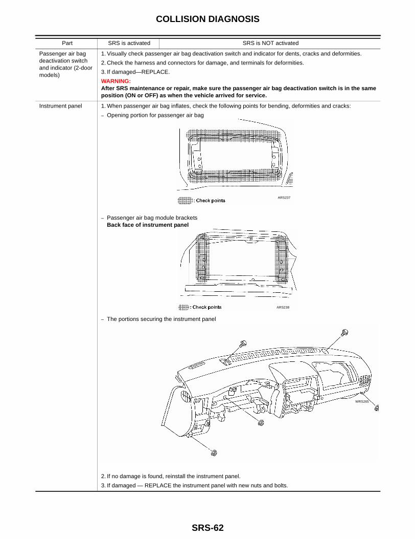
SRS-62
COLLISION DIAGNOSIS
Passenger air bag deactivation switch and indicator (2-door models)
1. Visually check passenger air bag deactivation switch and indicator for dents, cracks and deformities.
2. Check the harness and connectors for damage, and terminals for deformities.
3. If damaged—REPLACE.
WARNING:After SRS maintenance or repair, make sure the passenger air bag deactivation switch is in the same position (ON or OFF) as when the vehicle arrived for service.
Instrument panel 1. When passenger air bag inflates, check the following points for bending, deformities and cracks:
– Opening portion for passenger air bag
– Passenger air bag module bracketsBack face of instrument panel
– The portions securing the instrument panel
2. If no damage is found, reinstall the instrument panel.
3. If damaged — REPLACE the instrument panel with new nuts and bolts.
Part SRS is activated SRS is NOT activated
ARS237
ARS238
WRS265