brake system - pdf.textfiles.com
TRANSCRIPT

BR-1
BRAKE SYSTEM
F BRAKES
CONTENTS
C
D
E
G
H
I
J
K
L
M
SECTION
A
B
BR
Revision: January 2005 2004 Pathfinder Armada
PRECAUTIONS .......................................................... 3Precautions for Supplemental Restraint System (SRS) “AIR BAG” and “SEAT BELT PRE-TEN-SIONER” .................................................................. 3Precautions for Brake System .................................. 3
PREPARATION ........................................................... 4Special Service Tool ................................................. 4Commercial Service Tools ........................................ 4
NOISE, VIBRATION, AND HARSHNESS (NVH) TROUBLESHOOTING ................................................ 5
NVH Troubleshooting Chart ..................................... 5BRAKE PEDAL .......................................................... 6
Inspection and Adjustment ....................................... 6INSPECTION ........................................................ 6ADJUSTMENT ...................................................... 6
Removal and Installation .......................................... 7REMOVAL ............................................................. 8INSPECTION AFTER REMOVAL ......................... 8INSTALLATION ..................................................... 8
BRAKE FLUID ............................................................ 9On-board Inspection ................................................. 9
LEVEL CHECK ..................................................... 9Drain and Refill ......................................................... 9Bleeding Brake System .......................................... 10
BRAKE PIPING AND HOSE .....................................11Hydraulic Circuit ......................................................11Removal and Installation of Front Brake Piping and Brake Hose .............................................................11
REMOVAL ............................................................11INSTALLATION ................................................... 12
Removal and Installation of Rear Brake Piping and Brake Hose ............................................................ 12
REMOVAL ........................................................... 12INSTALLATION ................................................... 12
Inspection After Installation .................................... 13BRAKE MASTER CYLINDER .................................. 14
On-board Inspection ............................................... 14LEAK INSPECTION ............................................ 14
Removal and Installation ........................................ 14REMOVAL ........................................................... 14
INSTALLATION ................................................... 15Disassembly and Assembly .................................... 15
DISASSEMBLY ................................................... 15ASSEMBLY ......................................................... 15
BRAKE BOOSTER ................................................... 16On-Vehicle Service ................................................. 16
OPERATING CHECK .......................................... 16AIRTIGHT CHECK .............................................. 16
Removal and Installation ........................................ 17REMOVAL ........................................................... 17INSPECTION AFTER REMOVAL ....................... 17INSTALLATION ................................................... 18
VACUUM LINES ....................................................... 19Removal and Installation ........................................ 19Inspection ............................................................... 19
VISUAL INSPECTION ......................................... 19CHECK VALVE INSPECTION ............................. 19
FRONT DISC BRAKE ............................................... 20On-vehicle Inspection ............................................. 20
PAD WEAR INSPECTION ................................... 20Components ........................................................... 20Removal and Installation of Brake Pad .................. 21
REMOVAL ........................................................... 21INSTALLATION ................................................... 21
Removal and Installation of Brake Caliper Assembly and Disc Rotor ........................................................ 21
REMOVAL ........................................................... 21INSTALLATION ................................................... 21
Disassembly and Assembly of Brake Caliper Assembly ................................................................ 22
DISASSEMBLY ................................................... 22CALIPER INSPECTION ...................................... 23ASSEMBLY ......................................................... 23DISC ROTOR INSPECTION ............................... 24BRAKE BURNISHING PROCEDURE ................. 24
REAR DISC BRAKE ................................................. 25On-vehicle Inspection ............................................. 25
PAD WEAR INSPECTION ................................... 25Components ........................................................... 25Removal and Installation of Brake Pad .................. 26
BR-2Revision: January 2005 2004 Pathfinder Armada
REMOVAL ........................................................... 26INSTALLATION .................................................... 26
Removal and Installation of Brake Caliper Assembly and Disc Rotor ........................................................ 26
REMOVAL ........................................................... 26INSTALLATION .................................................... 26
Disassembly and Assembly of Brake Caliper Assembly ................................................................ 27
DISASSEMBLY ................................................... 27CALIPER INSPECTION ...................................... 27ASSEMBLY ......................................................... 27DISC ROTOR INSPECTION ............................... 28BRAKE BURNISHING PROCEDURE ................. 29
SERVICE DATA AND SPECIFICATIONS (SDS) ......30General Specifications ............................................30Brake Pedal ............................................................30Brake Booster .........................................................30Check Valve ............................................................30Front Disc Brake .....................................................30Rear Disc Brake ......................................................31

PRECAUTIONS
BR-3
C
D
E
G
H
I
J
K
L
M
A
B
BR
Revision: January 2005 2004 Pathfinder Armada
PRECAUTIONS PFP:00001
Precautions for Supplemental Restraint System (SRS) “AIR BAG” and “SEAT BELT PRE-TENSIONER” EFS0037V
The Supplemental Restraint System such as “AIR BAG” and “SEAT BELT PRE-TENSIONER”, used alongwith a front seat belt, helps to reduce the risk or severity of injury to the driver and front passenger for certaintypes of collision. This system includes seat belt switch inputs and dual stage front air bag modules. The SRSsystem uses the seat belt switches to determine the front air bag deployment, and may only deploy one frontair bag, depending on the severity of a collision and whether the front occupants are belted or unbelted.Information necessary to service the system safely is included in the SRS and SB section of this Service Man-ual.WARNING:● To avoid rendering the SRS inoperative, which could increase the risk of personal injury or death
in the event of a collision which would result in air bag inflation, all maintenance must be per-formed by an authorized NISSAN/INFINITI dealer.
● Improper maintenance, including incorrect removal and installation of the SRS, can lead to per-sonal injury caused by unintentional activation of the system. For removal of Spiral Cable and AirBag Module, see the SRS section.
● Do not use electrical test equipment on any circuit related to the SRS unless instructed to in thisService Manual. SRS wiring harnesses can be identified by yellow and/or orange harnesses orharness connectors.
Precautions for Brake System EFS0037W
● Refer to MA-11, "RECOMMENDED FLUIDS AND LUBRICANTS" for recommended brake fluid.● Do not reuse drained brake fluid.● Be careful not to splash brake fluid on painted areas.● To clean or wash all parts of master cylinder, disc brake caliper and wheel cylinder, use clean brake fluid.● Do not use mineral oils such as gasoline or kerosene. They will ruin rubber parts of the hydraulic system.● Use flare nut wrench when removing and installing brake tube.● Always check tightening torque when installing brake lines.● Before working, turn ignition switch to OFF and disconnect con-
nectors for ABS actuator and electric unit (control unit) or batteryterminals.
● Burnish the brake contact surfaces after refinishing or replacingdrums or rotors, after replacing pads or linings, or if a soft pedaloccurs at very low mileage. Refer to BR-24, "BRAKE BURNISH-ING PROCEDURE" .
WARNING:● Clean brake pads and shoes with a waste cloth, then wipe
with a dust collector.
SBR686C

BR-4
PREPARATION
Revision: January 2005 2004 Pathfinder Armada
PREPARATION PFP:00002
Special Service Tool EFS005TW
The actual shapes of Kent-Moore tools may differ from those of special service tools illustrated here.
Commercial Service Tools EFS005TX
Tool number(Kent-Moore No.)Tool name
Description
—(J-46532)Brake and clutch pedal height measure-ment tool
Measuring brake pedal height
LFIA0227E
Tool name Description
1. Flare nut crowfoot2. Torque wrench
Removing and installing each brake pip-ing.a: 10 mm (0.39 in) / 12 mm (0.47 in)
Power tool Removing nuts, bolts and screws.
S-NT360
PBIC0190E
PBIC0191E
NOISE, VIBRATION, AND HARSHNESS (NVH) TROUBLESHOOTING
BR-5
C
D
E
G
H
I
J
K
L
M
A
B
BR
Revision: January 2005 2004 Pathfinder Armada
NOISE, VIBRATION, AND HARSHNESS (NVH) TROUBLESHOOTING PFP:00003
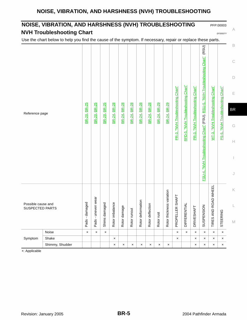
NVH Troubleshooting Chart EFS0037Y
Use the chart below to help you find the cause of the symptom. If necessary, repair or replace these parts.
×: Applicable
Reference page
BR
-20,
BR
-25
BR
-20,
BR
-25
BR
-20,
BR
-25
BR
-24,
BR
-28
BR
-24,
BR
-28
BR
-24,
BR
-28
BR
-24,
BR
-28
BR
-24,
BR
-28
BR
-24,
BR
-29
BR
-24,
BR
-29
PR
-3, "
NV
H T
roub
lesh
ootin
g C
hart
"
RF
D-5
, "N
VH
Tro
uble
shoo
ting
Cha
rt"
PR
-3, "
NV
H T
roub
lesh
ootin
g C
hart
"
FS
U-4
, "N
VH
Tro
uble
shoo
ting
Cha
rt"
(FS
U),
RS
U-5
, "N
VH
Tro
uble
shoo
ting
Cha
rt"
(R
SU
)
WT-
3, "
NV
H T
roub
lesh
ootin
g C
hart
"
PS
-5, "
NV
H T
roub
lesh
ootin
g C
hart
"
Possible cause andSUSPECTED PARTS
Pad
s -
dam
aged
Pad
s -
unev
en w
ear
Shi
ms
dam
aged
Rot
or im
bala
nce
Rot
or d
amag
e
Rot
or r
unou
t
Rot
or d
efor
mat
ion
Rot
or d
efle
ctio
n
Rot
or r
ust
Rot
or th
ickn
ess
varia
tion
PR
OP
ELL
ER
SH
AF
T
DIF
FE
RE
NT
IAL
DR
IVE
SH
AF
T
SU
SP
EN
SIO
N
TIR
ES
AN
D R
OA
D W
HE
EL
ST
EE
RIN
G
Symptom
Noise × × × × × × × × ×
Shake × × × × × ×
Shimmy, Shudder × × × × × × × × × × ×

BR-6
BRAKE PEDAL
Revision: January 2005 2004 Pathfinder Armada
BRAKE PEDAL PFP:46501
Inspection and Adjustment EFS003DJ
INSPECTION1. Inspect the brake pedal free height "H" from the lower dash panel using tool.
2. Adjust the height referring to the following specifications.CAUTION:When equipped with adjustable pedal, the pedal must be inthe forwardmost (closest to the floor) position for pedalheight measurement.
Brake Pedal Specifications
ADJUSTMENT1. Loosen the stop lamp switch and ASCD switch by turning 45° counterclockwise.
Tool number : — (J-46532)
WFIA0160E
Free height "H" : 182.3 - 192.3 mm (7.18 - 7.57 in)
Depressed pedal height "D" [under a force of 490 N (50 kg, 110 lb) with engine running]
: More than 90.3 mm (3.55 in)
Clearance between pedal stopper and threaded end of stop lamp switch and ASCD switch "C1 " or “C2 ”
: 0.74 - 1.96 mm (0.029 - 0.077 in)
Pedal play "A" : 3 - 11 mm (0.12 - 0.43 in)

BRAKE PEDAL
BR-7
C
D
E
G
H
I
J
K
L
M
A
B
BR
Revision: January 2005 2004 Pathfinder Armada
2. Loosen lock nut on the input rod, then turn input rod to adjust thepedal to specified height. When finished adjusting, tighten locknut.CAUTION:Make sure that the screw portion of the end of input rod islocated inside the clevis.
3. With the pedal pulled up and held by hand, press the stop lampswitch and the ASCD switch in until threaded ends contact pedalarm.
4. With the threaded ends of the stop lamp switch and ASCDswitch contacting the pedal arm, turn the switches 45° clockwiseto lock in place.CAUTION:Make sure that the gap (C) between the rubber stops andswitch ends are within specification.
5. Check the pedal play.CAUTION:Make sure that the stop lamp goes off when the pedal isreleased.
6. Start the engine and check the height of the brake pedal whendepressing it.
Removal and Installation EFS003DK
Lock nut : 18.5 N·m (1.9 kg-m, 14 ft-lb)
PFIA0436E
WFIA0232E

BR-8
BRAKE PEDAL
Revision: January 2005 2004 Pathfinder Armada
REMOVALWARNING:Do not deform the brake tube. CAUTION:● Before removal and installation the accelerator and brake pedals must be in the forward most
position (closest to the floor). This is to align the base position of the accelerator and brake ped-als.
● Do not disassemble the brake pedal adjusting mechanism.● Avoid damage from dropping the brake pedal assembly during handling.● Keep the brake pedal assembly away from water.1. Remove the lower driver instrument panel. Refer to IP-10, "Removal and Installation" .2. Remove the stop lamp switch and ASCD switch from the pedal assembly.3. Disconnect the adjustable brake pedal cable from the adjustable
pedal electric motor.● Unlock (1) then pull (2) the adjustable brake pedal cable to
disconnect it from the adjustable pedal electric motor asshown.
4. Remove snap pin and clevis pin from the clevis of brake booster.5. Remove mounting nuts and the pedal assembly.
● Temporarily install nuts by hand to support booster.CAUTION:● Before removal and installation the accelerator and brake
pedals must be in the forwardmost position (closest tothe floor). This is to align the base position of the accelerator and brake pedals.
● Do not disassemble the brake pedal adjusting mechanism.● Avoid damage from dropping the brake pedal assembly during handling.● Keep the brake pedal assembly away from water.
INSPECTION AFTER REMOVALCheck brake pedal for following items.● Crack or deformation of clevis pin stopper● Clevis pin deformation● Crack of any welded portion● Brake pedal bend
INSTALLATION1. Installation is in the reverse order of removal.
● Check the brake pedal for smooth operation. There should be no binding or sticking when applying orreleasing the brake pedal.
● Check the brake pedal adjustable feature for smooth operation. There should be no binding or stickingwhen adjusting the brake pedal forward or backward.
● After installing the brake pedal assembly in the vehicle, be sure to adjust it. Refer to BR-6, "Inspection andAdjustment" .
1. Brake pedal assembly 2. Snap pin 3. Clip
4. Stop lamp switch 5. Pedal pad 6. Clevis pin
7. ASCD cancel switch
LBIA0374E
SBR997

BRAKE FLUID
BR-9
C
D
E
G
H
I
J
K
L
M
A
B
BR
Revision: January 2005 2004 Pathfinder Armada
BRAKE FLUID PFP:KN100
On-board Inspection EFS00381
LEVEL CHECK● Make sure the fluid level in reservoir tank is within the standard
(between MAX and MIN lines).● Visually check around reservoir tank for fluid leaks.● If fluid level is excessively low, check brake system for leaks.● If brake warning lamp remains illuminated after parking lever is
released, check brake system for fluid leakage.
Drain and Refill EFS00382
CAUTION:● Refill with new brake fluid. Refer to MA-11, "Fluids and Lubricants" .● Do not reuse drained brake fluid.● Do not let brake fluid splash on the painted surfaces of the body. This might damage the paint, so
when splashing it, immediately wipe off the area and wash away with water.● Before servicing, disconnect actuator connector or battery negative cable.1. Connect a vinyl tube to each bleed valve.2. Depress brake pedal, loosen each bleed valve, and gradually
remove brake fluid.
3. Make sure there is no foreign material in reservoir tank, and refillwith new brake fluid.
4. Rest foot on brake pedal. Loosen bleed valve. Slowly depresspedal until it stops. Tighten bleed valve. Release brake pedal.Repeat this process a few times, then pause to add new brakefluid to master cylinder. Continue until new brake fluid flows out.Bleed air from brake system. Refer to BR-10, "Bleeding BrakeSystem" .
WFIA0173E
SBR419C
SBR995

BR-10
BRAKE FLUID
Revision: January 2005 2004 Pathfinder Armada
Bleeding Brake System EFS00383
CAUTION:While bleeding, pay attention to master cylinder fluid level.1. Turn ignition switch OFF and disconnect ABS actuator and electric unit (control unit) connector or battery
negative cable.2. Connect a vinyl tube to the rear right bleed valve.3. Fully depress brake pedal 4 to 5 times.4. With brake pedal depressed, loosen bleed valve to let the air out, and then tighten it immediately.5. Repeat steps 3 and 4 until no more air comes out.6. Tighten bleed valve to the specified torque. Refer to BR-20, "Components" (front disc brake), BR-25,
"Components" (rear disc brake). 7. Perform steps 2 to 6 at each wheel, with master cylinder reservoir tank filled at least half way, bleed air
from the front left, rear left, and front right bleed valve, in that order.

BRAKE PIPING AND HOSE
BR-11
C
D
E
G
H
I
J
K
L
M
A
B
BR
Revision: January 2005 2004 Pathfinder Armada
BRAKE PIPING AND HOSE PFP:46210
Hydraulic Circuit EFS00384
CAUTION:● All hoses and piping (tubes) must be free from excessive bending, twisting and pulling.● Make sure there is no interference with other parts when turning steering both clockwise and
counterclockwise.● The brake piping is an important safety part. If a brake fluid leak is detected, always disassemble
the parts. Replace applicable part with a new one, if necessary.● Be careful not to splash brake fluid on painted areas; it way cause paint damage. If brake fluid is
splashed on painted areas, wash it away with water immediately.● Do not bend or twist brake hose sharply, or strongly pull it.● When removing components, cover connections so that no dirt, dust, or other foreign matter gets
in.● Refill with new brake fluid. Refer to MA-11, "Fluids and Lubricants" .● Do not reuse drained brake fluid.
Removal and Installation of Front Brake Piping and Brake Hose EFS00385
REMOVAL1. Drain brake fluid. Refer to BR-9, "Drain and Refill" .2. Using a flare nut wrench, remove brake tube from brake hose.3. Remove lock plate and brake hose from bracket.4. Remove union bolt and then remove brake hose from caliper assembly.
1. Actuator 2. Master cylinder 3. Brake booster
4. Connector
WFIA0278E

BR-12
BRAKE PIPING AND HOSE
Revision: January 2005 2004 Pathfinder Armada
INSTALLATION1. Install brake hose by aligning with the protrusion on caliper
assembly, and tighten union bolt to the specified torque.NOTE:Do not reuse copper washer.
2. Insert brake hose end through bracket, then secure it to bracketwith lock plate.
3. Install brake tube to brake hose, then tighten flare nut to thespecified torque using a flare nut wrench.
4. Refill brake fluid and bleed air. Refer to BR-10, "Bleeding BrakeSystem" .
Removal and Installation of Rear Brake Piping and Brake Hose EFS00386
REMOVAL1. Drain brake fluid. Refer to BR-9, "Drain and Refill" .2. Using a flare nut wrench, remove brake tube from brake hose.3. Remove lock plate and brake hose from bracket.4. Remove union bolt, and then remove brake hose from caliper assembly.
INSTALLATION1. Install brake hose by aligning with the protrusion on caliper
assembly, and tighten union bolt to the specified torque.NOTE:Do not reuse copper washer.
2. Insert brake hose end through bracket, then secure it to bracketwith lock plate.
3. Install brake tube to brake hose, then tighten flare nut to thespecified torque using a flare nut wrench.
4. Refill brake fluid and bleed air. Refer to BR-10, "Bleeding BrakeSystem" .
LFIA0214E
LFIA0213E
LFIA0212E
LFIA0213E

BRAKE PIPING AND HOSE
BR-13
C
D
E
G
H
I
J
K
L
M
A
B
BR
Revision: January 2005 2004 Pathfinder Armada
Inspection After Installation EFS00387
CAUTION:If a leak is detected at the connections, retighten it or, if necessary, replace the damaged part.1. Check brake lines (tubes and hoses), and connections for fluid leaks, damage, twist, deformation, contact
with other parts, and loose connections. Replace any damage parts.2. While depressing brake pedal under a force of 785 N (80 kg, 177 lb) with engine running for approximately
5 seconds, check for fluid leakage from each part.

BR-14
BRAKE MASTER CYLINDER
Revision: January 2005 2004 Pathfinder Armada
BRAKE MASTER CYLINDER PFP:46010
On-board Inspection EFS00388
LEAK INSPECTION● Check for leaks at master cylinder to brake booster attachment point, reservoir tank, and brake tube con-
nections.
Removal and Installation EFS00389
CAUTION:Be careful not to splash brake fluid on painted areas; it way cause paint damage. If brake fluid issplashed on painted areas, wash it away with water immediately.
REMOVAL1. Drain brake fluid. Refer to BR-9, "Drain and Refill" .2. Disconnect harness connectors for fluid level sensor and pressure sensors.3. Using a flare nut wrench, disconnect brake tube from master cylinder assembly.4. Remove master cylinder assembly mounting nuts and master cylinder assembly.
1. Reservoir cap 2. Fluid level sensor 3. Grommet
4. Master cylinder sub-assembly 5. Front pressure sensor 6. Rear pressure sensor
7. Reservoir tank 8. Seal
WFIA0378E

BRAKE MASTER CYLINDER
BR-15
C
D
E
G
H
I
J
K
L
M
A
B
BR
Revision: January 2005 2004 Pathfinder Armada
INSTALLATION● Installation is in the reverse order of removal.● Refill brake fluid and bleed air. Refer to BR-10, "Bleeding Brake System" .
CAUTION:● Refill with recommended brake fluid. Refer to MA-11, "RECOMMENDED FLUIDS AND LUBRI-
CANTS" .● Do not reuse drained brake fluid.
● Adjust brake pedal. Refer to BR-6, "Inspection and Adjustment" .
Disassembly and Assembly EFS0038B
DISASSEMBLYCAUTION:● Master cylinder cannot be disassembled.● Remove reservoir tank only when absolutely necessary.Pull reservoir tank off master cylinder sub-assembly, then remove grommets from master cylinder sub-assem-bly body.
ASSEMBLYCAUTION:● Never use mineral oil such as kerosene, gasoline during the cleaning and assembly process.● Do not drop parts. If a part is dropped, do not use it.1. Apply brake fluid or rubber grease to new grommets, then insert into master cylinder sub-assembly. Refer
to GI-45, "RECOMMENDED CHEMICAL PRODUCTS AND SEALANTS" .CAUTION:Do not reuse grommet.
2. Install reservoir tank onto master cylinder assembly.

BR-16
BRAKE BOOSTER
Revision: January 2005 2004 Pathfinder Armada
BRAKE BOOSTER PFP:47200
On-Vehicle Service EFS0038C
OPERATING CHECKWith engine stopped, change the vacuum to the atmospheric pres-sure by depressing brake pedal several times. Then with brakepedal fully depressed, start engine and when the vacuum pressurereaches the standard, make sure the clearance between brake pedaland floor panel decreases.CAUTION:Depressing pedal interval is approximately 5 seconds.
AIRTIGHT CHECK● Run engine at idle for approximately 1 minute, and stop it after
applying vacuum to booster. Depress brake pedal normally tochange the vacuum to the atmospheric pressure. Make sure dis-tance between brake pedal and floor panel gradually increases.
● Depress brake pedal while engine is running and stop enginewith pedal depressed. The pedal stroke should not change afterholding pedal down for 30 seconds.
CAUTION:Depressing pedal interval is approximately 5 seconds.
BRA0037D
SBR365AA

BRAKE BOOSTER
BR-17
C
D
E
G
H
I
J
K
L
M
A
B
BR
Revision: January 2005 2004 Pathfinder Armada
Removal and Installation EFS0038D
REMOVAL CAUTION:● Be careful not to deform or bend brake piping while removing and installing brake booster.● Replace clevis pin if it is damaged.● Be careful not to damage brake booster stud bolt threads. If brake booster is tilted or inclined dur-
ing installation, dash panel may damage the threads.● Attach the check valve in the correct direction.1. Remove engine room cover using power tool. Refer to EM-11, "Removal and Installation" .2. Remove engine air duct assembly. Refer to EM-14, "Removal and Installation" .3. Remove brake piping from brake master cylinder.4. Remove brake master cylinder. Refer to BR-14, "Removal and Installation" .5. Remove vacuum hose from brake booster. Refer to BR-19, "VACUUM LINES" .6. Disconnect active boost and delta stroke sensor harness connectors from brake booster assembly.7. Remove brake pedal attachment snap pin and clevis pin from inside the vehicle. 8. Remove nuts on brake booster and brake pedal assembly.9. Remove brake booster assembly from dash panel.
INSPECTION AFTER REMOVALOutput Rod Length Inspection1. Using a handy vacuum pump, apply a vacuum of – 66.7 kPa (–
500 mmHg, –19.69 inHg) to brake booster.2. Check output rod length.
1. Reservoir tank 2. Master cylinder 3. Gasket
4. Brake pedal 5. Lock nut 6. Spacer block
7. Brake booster 8. Active booster 9. Delta stroke sensor
WFIA0233E
Standard dimension when vacuum – 66.7 kPa (– 500 mmHg, – 19.69 inHg)
: 15.6 − 15.9 mm (0.614 − 0.626 in)
SBR208E

BR-18
BRAKE BOOSTER
Revision: January 2005 2004 Pathfinder Armada
INSTALLATION1. Loosen lock nut to adjust input rod length so that the length B (in
the figure) satisfies the specified value.
2. After adjusting “B”, temporarily tighten lock nut and installbooster assembly to the vehicle.● Install a gaskets and spacer block between booster assembly
and the dash panel.3. Connect brake pedal with clevis of input rod.4. Install pedal bracket mounting nuts and tighten them to the
specified torque.5. Install brake piping from brake master cylinder to ABS actuator. Refer to BR-11, "Hydraulic Circuit" .6. Connect active boost and delta stroke sensor harness connectors to brake booster assembly.7. Connect vacuum hose to brake booster.8. Install master cylinder to booster assembly. Refer to BR-17, "Removal and Installation" .9. Adjust the height and play of brake pedal.10. Tighten lock nut of input rod to the specified torque.11. Install engine air duct assembly. Refer to EM-14, "Removal and Installation" .12. Install engine room cover. Refer to EM-11, "Removal and Installation" .13. Refill new brake fluid and bleed air. Refer to BR-10, "Bleeding Brake System" .
Length “B” : 125 mm (4.92 in)
SGIA0060E

VACUUM LINES
BR-19
C
D
E
G
H
I
J
K
L
M
A
B
BR
Revision: January 2005 2004 Pathfinder Armada
VACUUM LINES PFP:41920
Removal and Installation EFS0038E
1. Disconnect vacuum hose from hose clip.2. Release clamps and disconnect vacuum hose. 3. Remove check valve from brake booster.4. Installation is in the reverse order of removal.
CAUTION:● Insert vacuum hose for at least 24 mm (0.94 in).● Do not use lubricating oil during assembly.
Inspection EFS0038F
VISUAL INSPECTIONCheck for improper assembly, damage and deterioration.
CHECK VALVE INSPECTIONAirtightness InspectionUse a suitable vacuum pump to check. Connect to brake boosterside of check valve.
1. Hose clip 2. Clamp 3. Vacuum hose
4. Check valve
LFIA0216E
SBR225B
Check valve specifi-cation
: Vacuum decrease should be within 1.3 kPa (10 mmHg, 0.39 inHg) for 15 seconds under a vacuum of – 66.7 kPa (– 500 mmHg, – 19.69 inHg)
LFIA0217E

BR-20
FRONT DISC BRAKE
Revision: January 2005 2004 Pathfinder Armada
FRONT DISC BRAKE PFP:41000
On-vehicle Inspection EFS0038G
PAD WEAR INSPECTION● Inspect the thickness of pad through cylinder body inspection
hole. Use a scale for inspection if necessary.
Components EFS003NV
WARNING:Clean dust on caliper and brake pad with a vacuum dust collector to minimize the hazard of airborneparticles or other materials.
Standard thickness : 11.88 mm (0.468 in)Repair limit thickness : 1.0 mm (0.039 in)
BRA0010D
1. Upper sliding pin 2. Sliding pin boot 3. Torque member bolt
4. Torque member 5. Piston seal 6. Piston
7. Inner pad 8. Pad retainer 9. Outer pad
10. Piston boot 11. Union bolt 12. Copper washer
13. Sliding pin bolt 14. Bleed valve 15. Cylinder body
16. Cap 17. Brake hose 18. Lower sliding pin
WFIA0393E

FRONT DISC BRAKE
BR-21
C
D
E
G
H
I
J
K
L
M
A
B
BR
Revision: January 2005 2004 Pathfinder Armada
CAUTION:● While removing cylinder body never depress brake pedal because piston will pop out. ● It is not necessary to remove bolts on torque member and brake hose except for disassembly or
replacement of caliper assembly. In this case, hang cylinder body with a wire so as not to stretchbrake hose.
● Do not damage piston boot.● Burnish brake contact surface after refinishing or replacing rotors, after replacing pads, or if a soft
pedal occurs at very low mileage. Refer to BR-24, "BRAKE BURNISHING PROCEDURE" .
Removal and Installation of Brake Pad EFS0038I
REMOVAL1. Remove tires from vehicle using power tool.2. Remove lower sliding pin bolt.3. Suspend cylinder body with a wire and remove pad and shim from torque member.
INSTALLATION1. Push pistons in so that pad is firmly installed and mount cylinder body to torque member.
NOTE:Using a disc brake piston tool (commercial service tool), etc., makes it easier to push in piston.CAUTION:By pushing in piston, brake fluid returns to master cylinder reservoir tank. Watch the level of thesurface of reservoir tank.
2. Attach pad retainer to torque member.CAUTION:When attaching pad retainer, attach it firmly so that it doesnot float up higher than torque member, as shown in the fig-ure.
3. Install lower sliding pin bolt and tighten it to the specified torque.Refer to BR-20, "Components" .
4. Check brake for drag.5. Install tires to the vehicle. Refer to WT-6, "Rotation" .
Removal and Installation of Brake Caliper Assembly and Disc Rotor EFS0038J
REMOVAL1. Remove tires from vehicle using power tool.2. Drain brake fluid as necessary. Refer to BR-9, "Drain and Refill" .
NOTE:Do not remove union bolt unless removing brake caliper assembly from vehicle.
3. Remove union bolt as necessary and torque member bolts, then remove brake caliper assembly from thevehicle.NOTE:Position brake caliper assembly aside using suitable wire, as necessary.NOTE:When servicing brake caliper, remove sliding pin bolts and caliper from torque member.
4. Remove disc rotor.
INSTALLATIONCAUTION:● Refill with new brake fluid. Refer to MA-11, "Fluids and Lubricants" . ● Do not reuse drained brake fluid.1. Install disc rotor.2. Install sliding pin bolts and torque member to caliper, if removed. Refer to BR-20, "Components" .
PFIA0273E

BR-22
FRONT DISC BRAKE
Revision: January 2005 2004 Pathfinder Armada
3. Install caliper assembly to the vehicle, then tighten torque mem-ber bolts to the specified torque. Refer to BR-20, "Components".CAUTION:● When attaching caliper assembly to the vehicle, wipe any
oil off knuckle spindle, washers and caliper assemblyattachment surfaces.
● Do not reuse caliper torque member bolts.
4. Install brake hose to brake caliper assembly, if removed, thentighten union bolt to the specified torque. Refer to BR-20, "Com-ponents" .CAUTION:● Do not reuse copper washers for union bolt.● Attach brake hose to caliper assembly together with
union bolt and washers.
5. Refill new brake fluid and bleed air. Refer to BR-10, "Bleeding Brake System" .6. Attach tires to the vehicle. Refer to WT-6, "Rotation" .
Disassembly and Assembly of Brake Caliper Assembly EFS0038K
DISASSEMBLY1. Remove sliding pin bolt, and then remove the pad, shim, shim cover, and pad retainer from the torque
member.
2. Remove sliding pins and sliding pin boots from torque member.3. Place a wooden block as shown in the figure, and blow air from
union bolt mounting hole to remove pistons and piston boots.CAUTION:Do not get your fingers caught in piston.
4. Using a flat-bladed screwdriver, remove piston seal from cylin-der body.CAUTION:Be careful not to damage cylinder inner wall.
LFIA0209E
LFIA0214E
MAA0272D
SFIA1301E

FRONT DISC BRAKE
BR-23
C
D
E
G
H
I
J
K
L
M
A
B
BR
Revision: January 2005 2004 Pathfinder Armada
CALIPER INSPECTIONCylinder BodyCAUTION:● Use new brake fluid for cleaning. Do not use mineral oils such as gasoline or kerosene.● Check inside surface of cylinder for score, rust, wear, damage or foreign materials. If any of the
above conditions are observed, replace cylinder body.● Minor damage from rust or foreign materials may be eliminated by polishing surface with a fine
emery paper. Replace cylinder body if necessary.
Torque MemberCheck for wear, cracks, and damage. If damage or deformation is present, replace the affected part.
PistonCheck piston for score, rust, wear, damage or presence of foreign materials. Replace if any of the above con-dition are observed. CAUTION:Piston sliding surface is plated, do not polish with emery paper even if rust or foreign materials arestuck to sliding surface.
Sliding Pins, and Sliding Pin BootsCheck sliding pin and sliding pin boot for wear, damage, and cracks. If damage or deformation is present,replace the affected part.CAUTION:Trailing/upper sliding pin must be replaced at each service.
ASSEMBLYCAUTION:Do not use NISSAN Rubber Grease (KRE00 00010, KRE00 00010 01) when assembling.1. Apply clean brake fluid to new piston seal and insert seal in to
groove on cylinder body.CAUTION:Do not reuse piston seal.
2. Apply brake fluid to piston and piston boot, then install pistonboot in to piston groove. CAUTION:Do not reuse piston boot.
3. Insert into cylinder body by hand and insert piston boot piston-side lip into piston groove.CAUTION:Press piston evenly and vary the pressing point to prevent cylinder inner wall from being rubbed.
4. Install sliding pins and sliding pin boots to torque member.CAUTION:Trailing/upper sliding pin must be replaced at each service.
WFIA0210E
WFIA0211E

BR-24
FRONT DISC BRAKE
Revision: January 2005 2004 Pathfinder Armada
5. Install cylinder body. Tighten sliding pin bolt to the specified torque. Refer to BR-20, "Components" .
DISC ROTOR INSPECTIONVisual InspectionCheck surface of disc rotor for uneven wear, cracks, and serious damage. If any of them is detected, replaceapplicable part.
Runout Inspection1. Using wheel nuts, fix disc rotor to wheel hub. (2 or more positions.)2. Inspect runout using a dial gauge. (Measured at 10mm (0.39 in)
inside the disc edge.)
NOTE:Make sure that wheel bearing axial end play is within the specifi-cations before measuring runout. Refer to FAX-5, "WHEELBEARING INSPECTION" .
3. If runout is outside the limit, find the minimum runout point byshifting mounting positions of disc rotor and wheel hub by onehole.
4. If runout still out of specification, turn rotor with on-car brakelathe.
Thickness InspectionUsing a micrometer, check thickness of disc rotor. If thickness iseither at or below the wear limit, or exceeds maximum uneven wear,replace disc rotor.
BRAKE BURNISHING PROCEDUREBurnish brake contact surface according to the following procedure after refinishing or replacing rotors, afterreplacing pads, or if a soft pedal occurs at very low mileage.CAUTION:Only perform this procedure under safe road and traffic conditions. Use extreme caution.1. Drive the vehicle on a straight smooth road at 50 km/h (31 MPH).2. Use medium brake pedal/foot effort to bring the vehicle to a complete stop from 50 km/h (31 MPH). Adjust
brake pedal/foot pressure such that vehicle stopping time equals 3 to 5 seconds.3. To cool brake system, drive the vehicle at 50 km/h (31 MPH) for 1 minute without stopping.4. Repeat steps 1 to 3, 10 times or more to complete the burnishing procedure.
Runout limit (on vehicle) : 0.04 mm (0.0016 in)
BRA0013D
Standard thickness : 26.0 mm (1.024 in)Repair limit thickness : 24.5 mm (0.965 in) Maximum uneven wear (Measured at 8 positions)
: 0.015 mm (0.0006 in)
SBR020B

REAR DISC BRAKE
BR-25
C
D
E
G
H
I
J
K
L
M
A
B
BR
Revision: January 2005 2004 Pathfinder Armada
REAR DISC BRAKE PFP:44000
On-vehicle Inspection EFS0038L
PAD WEAR INSPECTION● Inspect the thickness of pad through cylinder body inspection
hole. Use a scale for inspection if necessary.
Components EFS0038M
WARNING:Clean dust on caliper and brake pad with a vacuum dust collector to minimize the hazard of airborneparticles or other materials.
Standard thickness : 12.13 mm (0.478 in)Repair limit thickness : 1.0 mm (0.039 in)
BRA0010D
1. Union bolt 2. Brake hose 3. Copper washer
4. Cap 5. Bleed valve 6. Mounting bolt
7. Cylinder body 8. Piston seal 9. Piston
10. Piston boot 11. Knuckle slide 12. Sliding sleeve boot
13. Sliding sleeve 14. Inner pad 15. Outer pad
WFIA0236E

BR-26
REAR DISC BRAKE
Revision: January 2005 2004 Pathfinder Armada
CAUTION:● While removing cylinder body, never depress brake pedal because piston will pop out.● It is not necessary to remove bolts on torque member and brake hose except for disassembly or
replacement of caliper assembly. In this case, hang cylinder body with a wire so as not to stretchbrake hose.
● Do not damage piston boot.● Burnish brake contact surface after refinishing or replacing rotors, after replacing pads, or it a soft
pedal occurs at very low mileage. Refer to BR-29, "BRAKE BURNISHING PROCEDURE" .
Removal and Installation of Brake Pad EFS0038N
REMOVAL1. Remove tires from vehicle with power tool.2. Remove mounting bolt from the top mount.3. Swing cylinder body open, and remove pads.
INSTALLATION1. Push piston in so that pad is firmly attached and mount cylinder body to torque member.
NOTE:Using a disc brake piston tool (commercial service tool), makes it easier to push in the piston.CAUTION:By pushing in piston, brake fluid returns to master cylinder reservoir tank. Watch the level of thesurface of reservoir tank.
2. Install pads to cylinder body.3. Install top mounting bolt and tighten to specification.4. Check brake for drag.5. Install tires to the vehicle.
Removal and Installation of Brake Caliper Assembly and Disc Rotor EFS0038O
REMOVAL1. Remove tires from vehicle with power tool.2. Drain brake fluid. Refer to BR-9, "Drain and Refill" .3. Remove union bolt and mounting bolts, and remove brake cali-
per assembly.4. Remove disc rotor.
INSTALLATIONCAUTION:● Refill with new brake fluid. Refer to MA-11, "Fluids and Lubricants" .● Do not reuse drained brake fluid.1. Install disc rotor.2. Install caliper assembly to the vehicle, and tighten mounting bolts to specification. Refer to BR-25, "Com-
ponents" .CAUTION:Before installing caliper assembly to the vehicle, wipe off mounting surface of caliper assembly.
3. Install brake hose to caliper assembly and tighten union bolt to specification. Refer to BR-25, "Compo-nents" .CAUTION:● Do not reuse copper washer for union bolt.
LFIA0211E

REAR DISC BRAKE
BR-27
C
D
E
G
H
I
J
K
L
M
A
B
BR
Revision: January 2005 2004 Pathfinder Armada
● Securely attach brake hose to protrusion on caliper assembly.4. Refill new brake fluid and bleed air. Refer to BR-10, "Bleeding Brake System" .5. Install tires to the vehicle.
Disassembly and Assembly of Brake Caliper Assembly EFS0038P
DISASSEMBLY1. Remove pads from cylinder body.2. Remove sliding sleeve and boot from cylinder body.3. Place a wooden block as shown in the figure, and blow air from
union bolt mounting hole to remove piston and piston boot.CAUTION:Do not get your fingers caught in piston.
4. Using a flat-bladed screwdriver, remove piston seal from cylin-der body.CAUTION:Be careful not to damage cylinder inner wall.
CALIPER INSPECTIONCylinder BodyCAUTION:● Use new brake fluid to clean. Do not use mineral oils such as gasoline or kerosene. ● Check inside surface of cylinder for score, rust wear, damage or foreign materials. If any of the
above conditions are observed, replace cylinder body.● Minor damage from rust or foreign materials may be eliminated by polishing surface with a fine
emery paper. Replace cylinder body if necessary.
Torque MemberCheck for wear, cracks, and damage. If damage or deformation is present, replace the affected part.
PistonCAUTION:● Piston sliding surface is plated, do not polish with emery paper even if rust of foreign materials
are stuck to sliding surface.● Check piston for score, rust, wear, damage or presence of foreign materials. Replace if any of the
above conditions are observed.
Sliding Pin Bolts and Sliding Pin BootsMake sure there is no wear, damage, or cracks in sliding sleeve and sliding sleeve boots, and if there are,replace them.
ASSEMBLYCAUTION:Do not use NISSAN Rubber Grease (KRE00 00010, KRE00 00010 01) when assembling.
BRD0041D
PFIA0269E

BR-28
REAR DISC BRAKE
Revision: January 2005 2004 Pathfinder Armada
1. Apply clean brake fluid to new piston seal and insert in togroove on cylinder body.CAUTION:Do not reuse piston seal.
2. Apply brake fluid to piston and to piston boot, then install pistonboot in to piston groove. CAUTION:Do not reuse piston boot.
3. Insert into cylinder body by hand and insert piston boot piston-side lip into piston groove.CAUTION:Press piston evenly and vary the pressing point to prevent cylinder inner wall from being rubbed.
4. Install sliding boots and sleeves to cylinder body.
DISC ROTOR INSPECTIONVisual InspectionCheck surface of disc rotor for uneven wear, cracks, and serious damage. If any non-standard condition isdetected, replace applicable part.
Runout Inspection1. Using wheel nuts, install disc rotor to wheel hub. (2 or more positions.)2. Inspect runout using a dial gauge. [Measured at 10 mm (0.39 in)
inside disk edge.]
NOTE:Make sure that wheel bearing axial end play is within the specifi-cation before measuring runout. Refer to RAX-5, "On-VehicleInspection and Service" .
3. If runout is outside the limit, find the minimum runout point byshifting mounting positions of disc rotor and wheel hub by onehole.
4. If runout still out of specification, turn rotor with on-car brakelathe.
WFIA0210E
WFIA0211E
Runout limit (on vehicle) : 0.05 mm (0.0020 in)
BRA0013D

REAR DISC BRAKE
BR-29
C
D
E
G
H
I
J
K
L
M
A
B
BR
Revision: January 2005 2004 Pathfinder Armada
Thickness InspectionUsing a micrometer, check thickness of disc rotor. If thickness iseither at or below the wear limit, or exceeds maximum uneven wear,replace disc rotor.
BRAKE BURNISHING PROCEDUREBurnish brake contact surface according to the following procedure after refinishing or replacing rotors, afterreplacing pads, or if a soft pedal occurs at very low mileage.CAUTION:Only perform this procedure under safe road and traffic conditions. Use extreme caution.1. Drive the vehicle on a straight smooth road at 50 km/h (31 MPH). 2. Use medium brake pedal/foot effort to bring the vehicle to a complete stop from 50 km/h (31 MPH). Adjust
brake pedal/foot pressure such that vehicle stopping time equals 3 to 5 seconds. 3. To cool brake system, drive the vehicle at 50 km/h (31 MPH) for 1 minute without stopping.4. Repeat steps 1 to 3, 10 times or more to complete the burnishing procedure.
Standard thickness : 14.0 mm (0.551 in)Wear limit : 12.0 mm (0.472 in)Maximum uneven wear (measured at 8 positions)
: 0.015 mm (0.0006 in)
SBR020B

BR-30
SERVICE DATA AND SPECIFICATIONS (SDS)
Revision: January 2005 2004 Pathfinder Armada
SERVICE DATA AND SPECIFICATIONS (SDS) PFP:00030
General Specifications EFS0038Q
Unit: mm (in)
Brake Pedal EFS0038R
Brake Booster EFS0038S
Check Valve EFS0038T
Front Disc Brake EFS0038U
Front brake Brake model CLZ31VC
Rotor outer diameter × thickness 320 × 26 (12.60 × 1.02)
Pad Length × width × thickness 111.0 × 73.5 × 9.5 (4.73 × 2.894 × 0.374)
Cylinder bore diameter 51 (2.01)
Rear brake Brake model AD14VE
Rotor outer diameter × thickness 320 × 14 (12.60 × 0.55)
Pad Length × width × thickness 83.0 × 33.0 × 8.5 (3.268 × 1.299 × 0.335)
Cylinder bore diameter 48 (1.89)
Control valve Valve model Electric brake force distribution
Brake booster Booster model C215T
Diaphragm diameter 215 (8.46)
Recommended brake fluid Genuine NISSAN Super Heavy Duty Brake Fluid or equivalent
Brake pedal height (from dash panel top surface) 182.3 − 192.3 mm (7.18 − 7.57 in)
Depressed pedal height [under a force of 490 N (50 kg, 110 lb) with engine running]
More than 90.3 mm (3.55 in)
Clearance between stopper rubber and the threaded end of stop lamp switch
0.74 − 1.96 mm (0.029 − 0.077 in)
Pedal play 3 − 11 mm (0.12 − 0.43 in)
Input rod installation standard dimension 15.6 − 15.9 mm (0.614 − 0.626 in)
Vacuum leakage [at vacuum of – 66.7 kPa(– 500 mmHg, – 19.69 inHg)]
Within 1.3 kPa (10 mmHg, 0.39 inHg) of vacuum for 15 seconds
Brake model CLZ31VC
Brake padStandard thickness (new) 11.88 mm (0.468 in)
Repair limit thickness 1.0 mm (0.039 in)
Disc rotor
Standard thickness (new) 26.0 mm (1.024 in)
Repair limit thickness 24.5 mm (0.965 in)
Maximum uneven wear (measured at 8 positions) 0.015mm (0.0006 in)
Runout limit (with it attached to the vehicle) 0.04 mm (0.0016 in)

SERVICE DATA AND SPECIFICATIONS (SDS)
BR-31
C
D
E
G
H
I
J
K
L
M
A
B
BR
Revision: January 2005 2004 Pathfinder Armada
Rear Disc Brake EFS0038V
Brake model AD14VE
Brake padStandard thickness (new) 12.13 mm (0.478 in)
Repair limit thickness 1.0 mm (0.039 in)
Disc rotor
Standard thickness (new) 14.0 mm (0.551 in)
Repair limit thickness 12.0 mm (0.472 in)
Maximum uneven wear (measured at 8 positions) 0.015 mm (0.0006 in)
Runout limit (with it attached to the vehicle) 0.05 mm (0.0020 in)

BR-32
SERVICE DATA AND SPECIFICATIONS (SDS)
Revision: January 2005 2004 Pathfinder Armada