section 75-wa-1 wing skeleton - zenith aircraft company · section 75-wa-1 wing skeleton ... drill...
TRANSCRIPT
STOL CH750
Zenith Aircraft Company www.zenithair.com
WING SKELETON Section 75-WA-1 page 1 of 21
Revision 1.2 (5/9/12) © 2008 Zenith Aircraft Co.
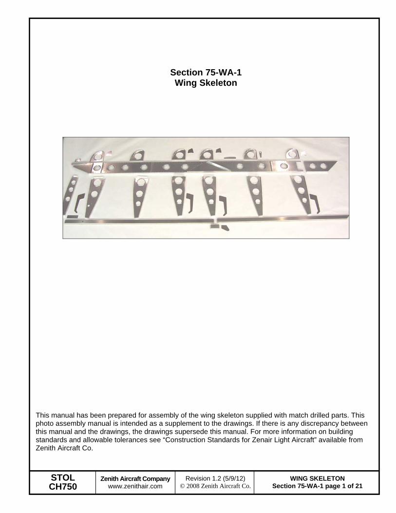
Section 75-WA-1 Wing Skeleton
This manual has been prepared for assembly of the wing skeleton supplied with match drilled parts. This photo assembly manual is intended as a supplement to the drawings. If there is any discrepancy between this manual and the drawings, the drawings supersede this manual. For more information on building standards and allowable tolerances see “Construction Standards for Zenair Light Aircraft” available from Zenith Aircraft Co.

STOL CH750
Zenith Aircraft Company www.zenithair.com
WING SKELETON Section 75-WA-1 page 2 of 21
Revision 1.2 (5/9/12) © 2008 Zenith Aircraft Co.
Trim an L angle to make 4 pieces 120mm long each.
P/N: L Length = 120mm
Mark lines on one flange of the L angles at the distances specified in the table to the right.
Measured from the left: 20mm 16mm 19mm 16mm 16mm 33mm

STOL CH750
Zenith Aircraft Company www.zenithair.com
WING SKELETON Section 75-WA-1 page 3 of 21
Revision 1.2 (5/9/12) © 2008 Zenith Aircraft Co.
With a #20 drill bit, drill stress relief holes in the radius of the L angle at the lines previously marked on the L angle.
Cut notches in the L angle flange. The notches are 90 degrees to the edge of the L angle and are made to the edge of the holes.

STOL CH750
Zenith Aircraft Company www.zenithair.com
WING SKELETON Section 75-WA-1 page 4 of 21
Revision 1.2 (5/9/12) © 2008 Zenith Aircraft Co.
With a round file, remove any burrs in the notches on the L angle.
P/N: 75W1-1SB Nose Rib (SB refers to being predrilled for the Slat Support, 75W3-6)
STOL CH750
Zenith Aircraft Company www.zenithair.com
WING SKELETON Section 75-WA-1 page 5 of 21
Revision 1.2 (5/9/12) © 2008 Zenith Aircraft Co.
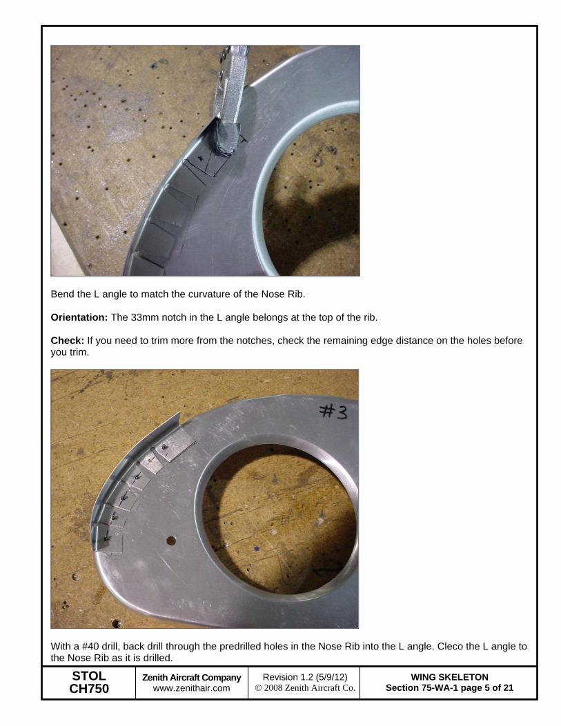
Bend the L angle to match the curvature of the Nose Rib. Orientation: The 33mm notch in the L angle belongs at the top of the rib. Check: If you need to trim more from the notches, check the remaining edge distance on the holes before you trim.
With a #40 drill, back drill through the predrilled holes in the Nose Rib into the L angle. Cleco the L angle to the Nose Rib as it is drilled.

STOL CH750
Zenith Aircraft Company www.zenithair.com
WING SKELETON Section 75-WA-1 page 6 of 21
Revision 1.2 (5/9/12) © 2008 Zenith Aircraft Co.
P/N: 75W3-6 Slat Support
Remove the L angle from the Nose Rib. Cleco the Slat Support and L angle to the Nose Rib. With a #30 drill bit, expand the predrilled hole and Cleco as the holes are drilled.

STOL CH750
Zenith Aircraft Company www.zenithair.com
WING SKELETON Section 75-WA-1 page 7 of 21
Revision 1.2 (5/9/12) © 2008 Zenith Aircraft Co.
Deburr and rivet the L angle and Slat Support to the Nose Rib with A4 rivets.
P/N: 75W2 Wing Spar (factory assembled)
P/N: 75W1-2K Wing Tank Rear Rib

STOL CH750
Zenith Aircraft Company www.zenithair.com
WING SKELETON Section 75-WA-1 page 8 of 21
Revision 1.2 (5/9/12) © 2008 Zenith Aircraft Co.
P/N: 75W1-2FB Wing Rear Rib (FB refers to being predrilled for the Flaperon Bracket, 75W3-5) P/N: 75W1-2 Wing Rear Rib
P/N: 75W1-1 Wing Nose Rib

STOL CH750
Zenith Aircraft Company www.zenithair.com
WING SKELETON Section 75-WA-1 page 9 of 21
Revision 1.2 (5/9/12) © 2008 Zenith Aircraft Co.
Cleco the Wing Tank Rear Rib at Stn. 280. Orientation: The rib flanges should point inboard. Orientation: The spar cap flanges point aft.
Cleco the Nose Ribs and Rear Ribs to the Spar. See the table to the right for stations for ribs with brackets. With a #20 drill bit, expand the holes through the Nose Ribs, Rear Ribs, and Spar. Orientation: All rib flanges point outboard, with the exception of 75W1-2K.
75W1-1SB & 75W1-2FB: Stn. 280 (75W1-2K) Stn. 1640 Stn. 2040 Stn. 3400 75W1-1 & 75W1-2: Stn. 960 Stn. 2720
STOL CH750
Zenith Aircraft Company www.zenithair.com
WING SKELETON Section 75-WA-1 page 10 of 21
Revision 1.2 (5/9/12) © 2008 Zenith Aircraft Co.
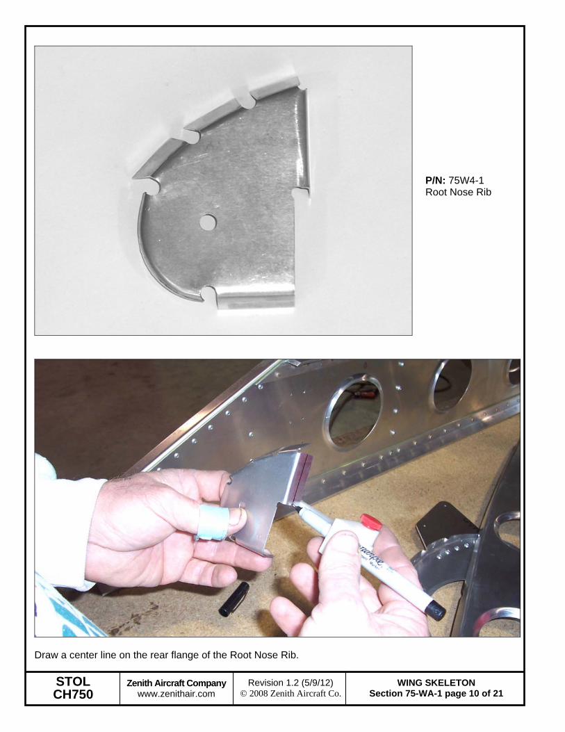
P/N: 75W4-1 Root Nose Rib
Draw a center line on the rear flange of the Root Nose Rib.

STOL CH750
Zenith Aircraft Company www.zenithair.com
WING SKELETON Section 75-WA-1 page 11 of 21
Revision 1.2 (5/9/12) © 2008 Zenith Aircraft Co.
Position the Root Nose Rib on the Spar with the center line on the rear flange visible through the predrilled holes in the Spar. Clamp the Root Nose Rib to the Spar (not shown in photo). Check: The Root Nose Rib should be square and flush with the Lower Spar Cap. Drill and Cleco the Root Nose Rib to the Spar with a #40 drill.
P/N: 75W4-2 Root Rear Rib

STOL CH750
Zenith Aircraft Company www.zenithair.com
WING SKELETON Section 75-WA-1 page 12 of 21
Revision 1.2 (5/9/12) © 2008 Zenith Aircraft Co.
Remove the Root Nose Rib from the Spar. Draw a center line on the front flange of the Root Rear Rib. Position the Root Rear Rib so the center line is visible through the predrilled holes in the Spar. Clamp the Root Rear Rib to the Spar (clamp not shown in photo). Check: The Root Rear Rib should be square and flush with the Lower Spar Cap. With a #40 drill bit, back drill and Cleco the Root Rear Rib to the Spar.
Cleco the Root Nose Rib to the Spar and Root Rear Rib. Expand the holes through the Root Nose Rib, Spar, and Root Rear Rib to 3/16”.
STOL CH750
Zenith Aircraft Company www.zenithair.com
WING SKELETON Section 75-WA-1 page 13 of 21
Revision 1.2 (5/9/12) © 2008 Zenith Aircraft Co.
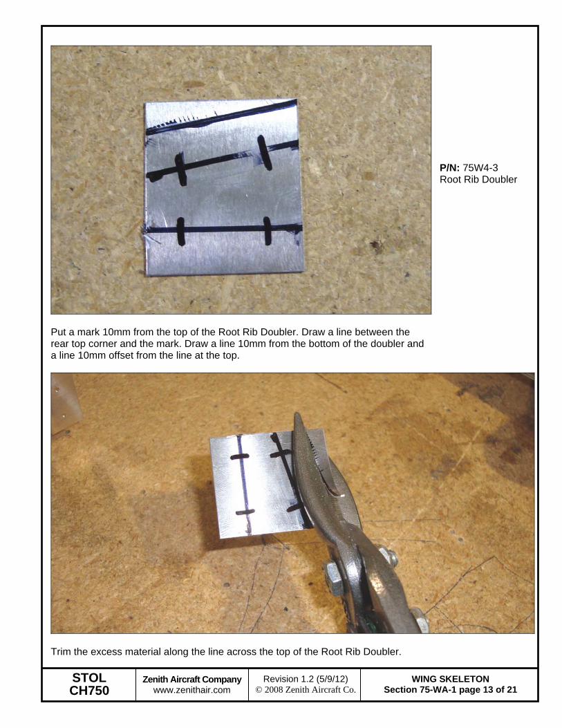
Put a mark 10mm from the top of the Root Rib Doubler. Draw a line between the rear top corner and the mark. Draw a line 10mm from the bottom of the doubler and a line 10mm offset from the line at the top.
P/N: 75W4-3 Root Rib Doubler
Trim the excess material along the line across the top of the Root Rib Doubler.

STOL CH750
Zenith Aircraft Company www.zenithair.com
WING SKELETON Section 75-WA-1 page 14 of 21
Revision 1.2 (5/9/12) © 2008 Zenith Aircraft Co.
Mark 4 rivet locations 9mm from the front and back edge on the lines. Position the Root Rib Doubler on the root ribs. Check: Make sure there is sufficient edge distance for the rivets in the root ribs. Clamp the Root Rib Doubler to the Root Ribs. With a #40 drill bit, drill the Root Rib Doubler, Root Nose Rib, and Root Rear Rib and Cleco. Expand the holes with a #20 drill bit.
Remove the Nose Rib at Stn. 2720.
P/N: 75W6-7 Tie Down Ring

STOL CH750
Zenith Aircraft Company www.zenithair.com
WING SKELETON Section 75-WA-1 page 15 of 21
Revision 1.2 (5/9/12) © 2008 Zenith Aircraft Co.
Position the Tie Down Ring on the Nose Rib. The Tie Down Ring should be flush with the back flange of the Nose Rib. The top of the hole in the Tie Down Ring should be flush with the bottom flange of the Nose Rib. Clamp the Tie Down Ring to the Nose Rib.
With a #40 drill back drill and Cleco the Tie Down Ring to the Nose Rib. With a #20 drill expand the holes and Cleco the Tie Down Ring to the Nose Rib. Reinstall the Nose Rib to the Spar at Stn. 2720.
STOL CH750
Zenith Aircraft Company www.zenithair.com
WING SKELETON Section 75-WA-1 page 16 of 21
Revision 1.2 (5/9/12) © 2008 Zenith Aircraft Co.
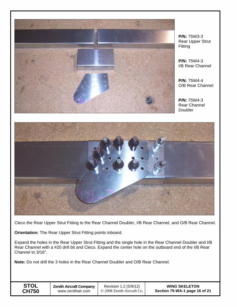
P/N: 75W3-3 Rear Upper Strut Fitting P/N: 75W4-3 I/B Rear Channel P/N: 75W4-4 O/B Rear Channel P/N: 75W4-3 Rear Channel Doubler
Cleco the Rear Upper Strut Fitting to the Rear Channel Doubler, I/B Rear Channel, and O/B Rear Channel. Orientation: The Rear Upper Strut Fitting points inboard. Expand the holes in the Rear Upper Strut Fitting and the single hole in the Rear Channel Doubler and I/B Rear Channel with a #20 drill bit and Cleco. Expand the center hole on the outboard end of the I/B Rear Channel to 3/16”. Note: Do not drill the 3 holes in the Rear Channel Doubler and O/B Rear Channel.

STOL CH750
Zenith Aircraft Company www.zenithair.com
WING SKELETON Section 75-WA-1 page 17 of 21
Revision 1.2 (5/9/12) © 2008 Zenith Aircraft Co.
P/N: 75W4-7 I/B Rear Channel Angle
Clamp the I/B Rear Channel Angle against the Rear Channel Doubler. Orientation: The I/B Rear Channel Angle is installed on the top of the I/B Rear Channel.

STOL CH750
Zenith Aircraft Company www.zenithair.com
WING SKELETON Section 75-WA-1 page 18 of 21
Revision 1.2 (5/9/12) © 2008 Zenith Aircraft Co.
Flip the Rear Channel assembly over to back drill through the I/B Rear Channel into the Angle. Use a #30 drill bit to back drill through the Rear Channel into the Angle and Cleco. Then expand the holes with a #20 drill bit and Cleco.
Cleco the Rear Channels to the Rear ribs on the wing. Wait to Cleco the Rear Root Doubler to the Rear Channel.

STOL CH750
Zenith Aircraft Company www.zenithair.com
WING SKELETON Section 75-WA-1 page 19 of 21
Revision 1.2 (5/9/12) © 2008 Zenith Aircraft Co.
P/N: 75W3-4 Rear Root Doubler
Slide the Rear Root Doubler between the Rear Root Rib and the Rear Channel. The Rear Root Doubler sets on top of the rear flange of the Wing Tank Rear Rib. Cleco the Rear Root Doubler to the Rear Channel. Use a #30 drill bit to expand the holes and Cleco. Then use a #20 drill bit to expand the holes and Cleco.
STOL CH750
Zenith Aircraft Company www.zenithair.com
WING SKELETON Section 75-WA-1 page 20 of 21
Revision 1.2 (5/9/12) © 2008 Zenith Aircraft Co.
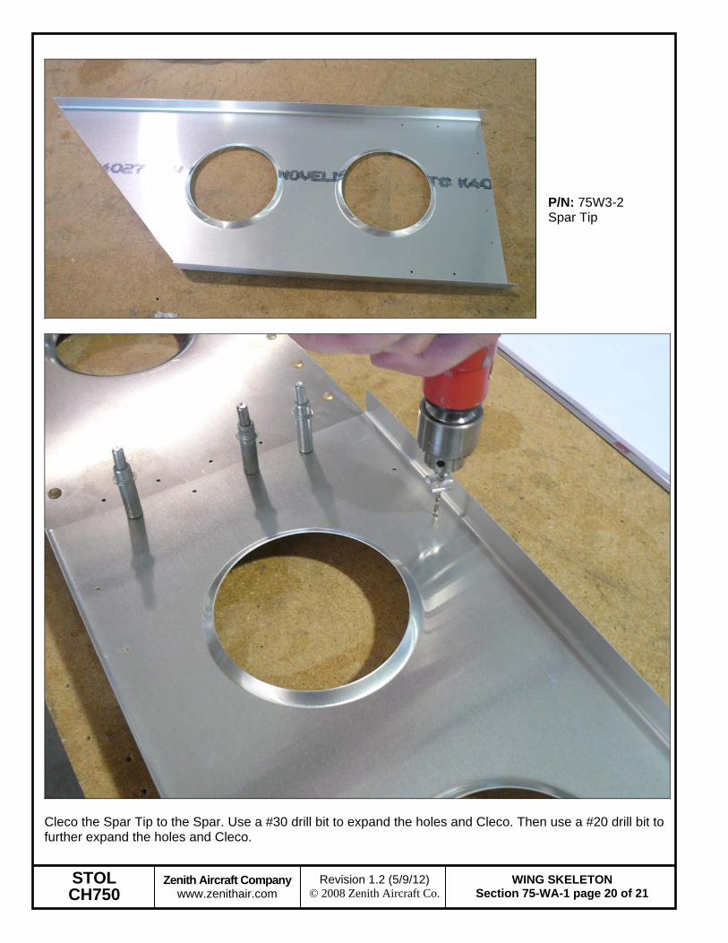
P/N: 75W3-2 Spar Tip
Cleco the Spar Tip to the Spar. Use a #30 drill bit to expand the holes and Cleco. Then use a #20 drill bit to further expand the holes and Cleco.

STOL CH750
Zenith Aircraft Company www.zenithair.com
WING SKELETON Section 75-WA-1 page 21 of 21
Revision 1.2 (5/9/12) © 2008 Zenith Aircraft Co.
Disassemble, deburr the holes, reassemble, and rivet the Wing Skeleton together. Reference: See page 75-WA-1 for rivet and bolt diameter information.