section 7 systems description and operation table of …
TRANSCRIPT

AFM 10.701-7
Section 7
V1.0 SYSTEMS DESCRIPTION
Rev. 14
DATE: 03 October 2018 7-i
SECTION 7
SYSTEMS DESCRIPTION AND OPERATION
TABLE OF CONTENTS
PARAGRAPH PAGE
7.1 AIRCRAFT 7-1
7.2 AIRFRAME 7-1
7.3 POWERPLANT 7-3
7.4 ENGINE CONTROLS 7-5
7.5 FLIGHT CONTROLS 7-6
7.6 LANDING GEAR 7-7
7.7 BRAKE SYSTEM 7-8
7.8 FUEL SYSTEM 7-9
7.9 ELECTRICAL SYSTEM 7-12
7.9.1 MASTER SWITCH PANEL 7-13
7.9.2 BREAKER PANEL 7-14
7.9.3 SWITCH PANEL 7-16
7.10 CUT-OFF 7-17
7.11 EXTERNAL POWER 7-18
7.12 EMERGENCY LOCATOR TRANSMITTER 7-19
7.13 INSTRUMENT PANEL AND PEDESTAL LAYOUT 7-20

AFM 10.701-7
Section 7
SYSTEMS DESCRIPTION V1.0
Rev. 14
7-ii DATE: 03 October 2018
SECTION 7
SYSTEMS DESCRIPTION AND OPERATION
TABLE OF CONTENTS
PARAGRAPH PAGE
7.14 ANNUNCIATOR PANEL 7-24
7.15 STALL WARNING SYSTEM 7-25
7.16 ENVIRONMENTAL SYSTEM 7-26
7.16.1 CABIN AIR HEATING / WINDSHIELD DEFROSTING SYSTEM
7-26
7.16.2 FRESH AIR SYSTEM 7-27
7.17 PITOT AND STATIC SYSTEM 7-28
7.18 DIGITAL COCKPIT 7-29
7.18.1 GARMIN G500 AVIONIC SYSTEM AND GARMIN
LRUS OVERVIEW
7-29
7.18.2 GARMIN G500 AVIONIC SYSTEM AND GARMIN LRUS COMPONENTS
7-32
7.18.3 GARMIN G500 AVIONIC SYSTEM AND GARMIN LRUS CONTROLS
7-38
7.18.4 MD302 STANDBY ATTITUDE MODULE 7-44
7.18.5 EDM-930 ENGINE DATA MANAGEMENT SYSTEM 7-45
7.18.6 ENGINE INDICATION SYSTEM (EIS) 7-47
7.18.7 GARMIN TERRAIN-SVT FEATURE 7-48
7.18.8 GARMIN ADS-B IN TRAFFIC FEATURE 7-50

AFM 10.701-7
Section 7
V1.0 SYSTEMS DESCRIPTION
Rev. 15
DATE: 21 December 2018 7-iii
SECTION 7
SYSTEMS DESCRIPTION AND OPERATION
TABLE OF CONTENTS
PARAGRAPH PAGE
7.18.9 SOFTWARE RELEASE NOTIFICATION 7-52
7.19 PLACARDS 7-54
AFM 10.701-7
Section 7
SYSTEMS DESCRIPTION V1.0
Rev. 14
7-iv DATE: 03 October 2018
- THIS PAGE INTENTIONALLY LEFT BLANK -
AFM 10.701-7
Section 7
V1.0 SYSTEMS DESCRIPTION
Rev. 14
DATE: 03 October 2018 7-1
SECTION 7
SYSTEMS DESCRIPTION AND OPERATION
7.1 AIRCRAFT
Vulcanair V1.0 is a four seats, single piston engine, high wing monoplane
aircraft, equipped with a fixed tricycle landing gear and digital cockpit.
7.2 AIRFRAME
The airframe for Vulcanair V1.0 aircraft is mainly of all-metal construction,
with dorsal fin, fairings and wing tips made of composite material.
The fuselage is made of all metal structure. It consists of two main parts
assembled (fwd/rear sections), fireproof bulkhead, floor, metal fittings and
other aluminum parts that allow the connection of main landing gear, wing,
strut, engine mount, seats and instrument panel. Several hard points are
incorporated in the fuselage to support the main aircraft components.
The forward side of the fuselage is a truss that includes the attaching point for
the wing-halves, the engine mount and the landing gear, while the rear side of
the fuselage is a metal semi-monocoque structure that consists of bulkheads,
stringers and stiffeners, to which all of outer skin is riveted.
The cabin may be accessed through three doors (composite material) provided
with a proper interlocking system: two crew doors located at the forward LH
side (pilot door) and RH side (co-pilot door) of the fuselage and a cabin
entrance door for passenger (passenger door) located at the RH side of the
fuselage. An access door to the baggage compartment is located just aft the
passenger door. An internal sliding door installed behind the rear bench
permits another access to the baggage compartment.
Windows include a windshield, an upper windshield, a rear window and a LH
side window.

AFM 10.701-7
Section 7
SYSTEMS DESCRIPTION V1.0
Rev. 14
7-2 DATE: 03 October 2018
The empennages are made of all metal stressed-skin, full cantilever, consisting
of a vertical tail (fin and rudder) and a horizontal tail (stabilator). Only the
stabilator is provided with trim tab and also it incorporates one torque tube
that is hinged to the aft bulkhead assembly of the fuselage.
The rudder (statically balanced) is connected to the vertical fin through two
hinges on the rear spar of the fin (bellcrank connected to lower hinge for
movement transmission) and it is cable controlled.
The stabilator unit is an all movable tail plane (statically balanced) and it
consists of two symmetrical metal semi-monocoque halves coupled with a
hinge torque tube assembled to the rear bulkhead of the fuselage; it is push-
pull rods controlled. The stabilator is provided with one trim tab in two rigidly
jointed halves, one for each half-stabilator.
The wing is composed of two halves-wing. Each one is connected to the
fuselage by means of two bolt attachments and a single strut brace per side.
Each wing is made of all metal stressed-skin, full cantilever consisting of a
torsion box with removable aluminum leading edge and carbon fiber tip.
A rigid metal removable fuel tank is located in each half-wing in an opportune
wing box compartment between the wing spars and appropriately supported
by the wing structure.
An aileron and flap (all metal construction) are attached to each half-wing.
Static wicks are installed on the wing and tail plane trailing edges to clear the
aircraft of surface static electricity.
The fixed tricycle landing gear with a steerable nose gear (nose wheel is
steerable through the rudder pedals).
A tapered leg, positioned crossways to the fuselage and attached to the
fuselage structure (under the seats in truss central section) by means of a
mounting bracket and bolt, supports each main wheel.
The metal nose gear-leg is made with welded brackets and it is pivotally
attached to the engine mount; the nose fork attaches and pivots at the lower
end of the nose gear. Shock absorption for the steerable nose wheel is
provided by a spring strut cylinder (oil and metallic spring) installed between
nose gear strut and nose wheel fork.
Brakes are hydraulically actuated through the rudder pedal tips.

AFM 10.701-7
Section 7
V1.0 SYSTEMS DESCRIPTION
Rev. 14
DATE: 03 October 2018 7-3
7.3 POWERPLANT
(Refer to Figure 7-1)
Vulcanair V1.0 aircraft is powered by one engine Lycoming model IO-360-
M1A, fuel injected, direct drive, four cylinders, horizontally opposed (361 cu-
in displacement), air cooled with down exhaust outlets. This engine is
supplied with a starter and an RSA-5AD1 type fuel injection system.
Lycoming IO-360-M1A engine has a rated maximum continuous power of
180 HP at 2700 RPM at standard sea level conditions and a compression ratio
of 8.5:1.
The engine is enclosed by cowlings consisting of eight panels; two LH/RH
hinged upper side cowlings permit an easy access to the engine internal area.
Lycoming IO-360-M1A engine is securely installed to the aircraft fuselage
truss through its tubular mount; this one is secured to the fuselage truss by
means of four attachment points easily identifiable on the fireproof bulkhead.
The fireproof bulkhead separates the engine compartment from the rest of the
fuselage and supports various aircraft components on both fwd and aft sides.
A total of four engine shock mounts are installed between the engine and the
related four mounting pads to isolate the airframe from the engine vibrations.
Lycoming IO-360-M1A engine is coupled with Hartzell propeller model HC-
C2YR-1BFP/F7497, two-blade, constant speed, non-counterweighted, single-
acting, hydraulically actuated, controlled by an engine speed sensing device
(governor) to maintain a constant engine/propeller RPM by changing the
blade angle; no feathering capability is added.
The propeller is an aluminum blade model with a swept tip and a diameter of
74 in (1.88 m).
Both aviation fuel (AVGAS) and automotive fuel (MOGAS) types are
approved for use in Lycoming IO-360-M1A engine (as per Lycoming Service
Instruction No.1070).
The engine lubrication system consists of a wet sump, engine driven oil pump,
an oil filter, and an oil cooler.
One electric start boost system “SlickSTART™” manufactured by Champion
Aerospace is installed on the aircraft in order to improve the ignition system.

AFM 10.701-7
Section 7
SYSTEMS DESCRIPTION V1.0
Rev. 14
7-4 DATE: 03 October 2018
Figure 7-1 Powerplant system overview

AFM 10.701-7
Section 7
V1.0 SYSTEMS DESCRIPTION
Rev. 14
DATE: 03 October 2018 7-5
7.4 ENGINE CONTROLS
(Refer to Figure 7-2)
The engine and propeller are operated by three sets of control levers mounted
on the control pedestal below and at the center of the instrument panel.
The controls are (from LH to RH): power lever, propeller speed lever and
mixture control lever.
Pedestal control lever friction is adjusted by a friction wheel located on the
RH side of the control pedestal. Friction should be set for a smooth, but not
loose movement of the control levers. To increase friction, rotate the wheel
clockwise, to decrease friction rotate the wheel counterclockwise.
The alternate air door, as well as the air stoppage to the engine, can be
controlled through the alternate air control handle. This last one is located on
the central pedestal, just below the engine and propeller control levers.
Figure 7-2 Control pedestal overview
POWER
LEVER
MIXTURE
CONTROL
LEVER
PROPELLER
SPEED
LEVER
STABILATOR
TRIM
CONTROL
WHEEL

AFM 10.701-7
Section 7
SYSTEMS DESCRIPTION V1.0
Rev. 14
7-6 DATE: 03 October 2018
7.5 FLIGHT CONTROLS (Refer to Figures 7-2 and 7-3)
Primary flight controls are conventional equipment, consisting of a control
wheel which operates the ailerons and stabilator, and pedals which operate the
rudder. Duplicate controls are provided for the co-pilot.
The two ailerons (statically balanced) are controlled through cables and push-
pull rods.
The stabilator (statically balanced) is controlled through push-pull rods.
The rudder (statically balanced) is controlled through cables.
Secondary controls are provided by the stabilator trim tab.
Stabilator trim is operated by a wheel, located on the LH side of the control
pedestal, which turns a chain sprocket.
To show tab position, an indicator is mounted close to the trim control wheel.
The trailing edge single slot wing flaps, one on each wing, are electrically
operated by an actuator, installed in correspondence of the RH wing root, and
activated by a control switch located on the instrument panel. This actuator is
connected to a lever which operates the RH wing flap through a push-pull rod
and the LH wing lever through a torque tube assembled to the fuselage truss.
The LH wing flap is connected to the lever by a push-pull rod.
Electrical up and down limit switches are provided to safeguard against over-
travel.
The flap position is mechanically/electrically transmitted to the indicator
located next to the related control switch.
Figure 7-3 Flap position indicator and related control switch
FLAP
CONTROL
SWITCH
FLAP
POSITION
INDICATOR

AFM 10.701-7
Section 7
V1.0 SYSTEMS DESCRIPTION
Rev. 14
DATE: 03 October 2018 7-7
7.6 LANDING GEAR
Vulcanair V1.0 aircraft is equipped with a fixed tricycle landing gear with a
steerable nose gear.
The main landing gear consists of two cantilever legs, two wheels with brakes
and two main wheel fairings (optional equipment).
The tapered leaf-springs are positioned crossways to the fuselage and attached
to the fuselage structure (under the seats in truss central section) by means of
two mounting brackets and bolts.
A wheel axle is attached to the lower end of each landing gear strut with four
bolts.
The two main wheels are equipped with 6.00-6, 6-ply tires and with single disc
hydraulic brake assemblies, installed on the inboard side of each wheel, which
are actuated by individual toe brake cylinders mounted on the rudder pedals.
The nose gear consists of one welded tubular strut pivotally attached to the
engine mount and linked to the rudder pedals to provide ground control, one
shock absorber fitted directly on the nose landing gear structure and one nose
wheel fairing (optional equipment).
The nose gear-leg is made with welded brackets. The nose fork attaches and
pivots at the lower end. An axle bolt and nut fasten the axle, spacer, wheel and
tire assembly to the nose fork.
The forward bottom end of the nose gear strut has a horizontal pivot for the
nose wheel fork. The nose wheel fork with the nose gear wheel can thus only
move up and down.
Shock absorption for the steerable nose wheel is provided by a spring strut
cylinder (oil and metallic spring) installed between nose gear strut and nose
wheel fork.
Nose wheel steering is accomplished through use of the rudder pedals. The
nose wheel is equipped with 5.00-5, 6-ply tire.

AFM 10.701-7
Section 7
SYSTEMS DESCRIPTION V1.0
Rev. 14
7-8 DATE: 03 October 2018
7.7 BRAKE SYSTEM
(Refer to Figure 7-4)
The brakes are hydraulically operated by individual hydraulic brake cylinders
mounted on the rudder pedals. To operate the brakes, apply toe pressure
against the top of the rudder pedals.
The parking brake consists of one manually operated knob assembly, installed
on the control pedestal, and connected to the parking brake valve.
When pressure is applied to the brake system and the parking brake knob is
rotated to “LOCK”, the valve holds the pressure on the brake assemblies until
released. Rotate to “UNLOCK” the knob to release the parking brake.
Hydraulic fluid for the brake cylinders is contained in a remote reservoir
installed on the LH hand side in front of the fireproof bulkhead.
Figure 7-4 Brake system block architecture

AFM 10.701-7
Section 7
V1.0 SYSTEMS DESCRIPTION
Rev. 14
DATE: 03 October 2018 7-9
7.8 FUEL SYSTEM
(Refer to Figure 7-5)
The main components of the fuel system are: Fuel Tanks, Fuel Selector Valve,
Low Pressure Fuel Filter and Auxiliary Fuel Pump (electrically operated).
Fuel is stored in two wing tanks (one per wing). Each fuel tank is provided
with sump (with flush drain valve) and finger strainer.
The total fuel capacity for each tank is 100 liters (26.4 USG), of which 95
liters (25.1 USG) are usable. Fuel exchange between fuel tanks is not possible.
Although only one fuel tanks configuration can be installed on the aircraft,
two fuel types are approved for use in Lycoming IO-360-M1A engines:
a) Aviation Fuels (AVGAS)
b) Automotive Fuels (MOGAS)
Due to the higher volatility of MOGAS as compared to AVGAS, to reduce the
vapour lock issue, an additional fuel line has been installed; its purpose is to
increase the fuel circulating through the fuel hoses in engine compartment,
thus reducing vapour formation potential. As per above, the fuel system
consists of two separate fuel lines:
1. Fuel supply line (main), that carries the fuel from the fuel tanks to the injector.
2. Fuel return line, that carries back the fuel from the injector to the fuel tanks.
Fuel is gravity fed, through the main fuel line (tube 3/8"), from the wing tanks
to the fuel selector valve in the cabin at the control pedestal plate.
From the selector valve, the fuel flows through the fireproof bulkhead and
reaches the low pressure fuel filter installed fwd the fireproof bulkhead. The
filtered fuel flows to the auxiliary fuel pump and then to the Lycoming engine
pump installed on the engine’s accessory housing. The engine driven fuel
pump provides the fuel to the injector; excess of fuel return back to the fuel
tank through the fuel return line (tube 1/4").
The aircraft is equipped with a three-positions fuel selector valve. The
positions for the fuel control system operations are: “OFF”, “RIGHT” and
“LEFT”. The pointer of the fuel selector control knob indicates the position of
the fuel selector valve. The fuel selector control knob allows the pilot to select
the LH or RH wing fuel tank to supply the engine. The pilot shuts off the
engine selecting the “OFF” position. To select the “OFF” position, it is
required to raise the red button on handle and then rotate the concerned handle.

AFM 10.701-7
Section 7
SYSTEMS DESCRIPTION V1.0
Rev. 14
7-10 DATE: 03 October 2018
When the pilot changes from LH to RH tank and viceversa, it is not possible
to pass over the “OFF” position.
The electrically operated auxiliary fuel pump provides the fuel pressure for
priming during engine starting, and supplies fuel to the engine, during the
take-off and landing operating phase, in case of mechanical pump malfunction
or failure. The auxiliary fuel pump must be used also for switching from one
tank to the other.
A control switch labelled “FUEL PUMP” is provided on the master switch
panel. Function of auxiliary fuel pump is indicated by means of an advisory
light on the annunciator panel, installed on the top of the instrument panel. A
green advisory light labelled “FUEL PUMP ON” (when lighted) informs the
pilot that the auxiliary fuel pump is switched ON.
The fuel system can be monitored by means of the JPI EDM-930 display that
interfaces directly with the engine, the electrical sensors and the fuel senders,
and uses its own LCD to display all the data (fuel pressure, fuel flow and
RH/LH tank fuel quantity information) to the pilot.
The block architecture of the fuel system can be generally schematized in
Figure 7-5 below.

AFM 10.701-7
Section 7
V1.0 SYSTEMS DESCRIPTION
Rev. 14
DATE: 03 October 2018 7-11
Figure 7-5 Fuel system block architecture

AFM 10.701-7
Section 7
SYSTEMS DESCRIPTION V1.0
Rev. 14
7-12 DATE: 03 October 2018
7.9 ELECTRICAL SYSTEM
(Refer to Figures 7-6 through 7-9)
Electrical power is supplied by 28 Volt, direct current, negative ground
electrical system.
The power generation is realized through the following basic elements:
• ALTERNATOR
• MAIN BATTERY
The alternator is able to provide up to 70A current output.
Alternator output voltage regulation is performed using a voltage regulator
which senses alternator unregulated voltage and modulates alternator field
current in order to stabilize its voltage.
The installed voltage regulator Plane Power p/n R1224B (Vulcanair p/n
NV7.003-130A) is a solid-state voltage regulator with over-voltage protection,
field short (over-current) protection and reverse battery protection, and also
supports precision load sharing for twin applications, and an alternator
inoperative lamp.
The Main Battery is lead-acid battery Concorde p/n RG24-12 (Vulcanair p/n
NV7.003-149B) with characteristics 24Vdc@11Ah. It provides for engine
starting and as a reserve power source in case of alternator power loss.
The voltage generated by the power generation system is made available
immediately on Main Bus Bar and, after activation of associated switch, to the
other two bus bars, Avionic Bus Bar and Secondary Cut-Off Bus Bar.
The Avionic Bus is activated through a dedicated switch located on the
instrument panel and operated by the pilot, while the Secondary Cut-Off Bus is
derived from the Main Bus through a switch that is automatically opened by a
status signal coming from the voltage regulator in case of an alternator failure.
In this way all the loads connected on this bar will be instantly powered off,
avoiding a current draw from battery during the emergency phase.
The three power bus bars composing the power distribution system provide
the energy to all the electrical loads. Each of them has a dedicated breaker for
over current protection.
The block architecture of the electrical power and distribution system can be
generally schematized as shown in Figure 7-6 below.
The COM1 switch is provided to have the COM1 power supplied by the
battery in case of complete bus bar failure.

AFM 10.701-7
Section 7
V1.0 SYSTEMS DESCRIPTION
Rev. 14
DATE: 03 October 2018 7-13
Figure 7-6 Electrical system block architecture
The management of the electrical generation and distribution is done by means of:
• Master Switch Panel
• Breaker Panel
• Switch Panel
7.9.1 MASTER SWITCH PANEL
The master switch panel is located on the LH side of the pilot wheel.
Figure 7-7 Master switch panel

AFM 10.701-7
Section 7
SYSTEMS DESCRIPTION V1.0
Rev. 15
7-14 DATE: 21 December 2018
7.9.2 BREAKER PANEL
The breaker panel is located under the pilot wheel and divided in the
following areas:
• MAIN BUS BREAKERS
• AVIONIC BUS BREAKERS
• SECONDARY BUS BREAKERS
Only for aircraft s/n 1001 and 1002
For aircraft from s/n 1003 onwards
Figure 7-8 Breaker panel
In the following table have been described the effects in terms of losing
function(s) when every single breaker is pulled out:
BREAKERS LOST FUNCTIONS
PFD • PRIMARY FLIGHT DISPLAY
ADC • AIR DATA COMPUTER
AHRS • AHRS
AUDIO PNL/MKR
Note: In case of failure of Audio
Panel, the pilot is automatically
connected to COM1
• COM2/NAV2 AUDIO
• NAV1 AUDIO
• MARKER BEACON
COM1 • COM1
GPS/NAV1 • GPS/NAV1

AFM 10.701-7
Section 7
V1.0 SYSTEMS DESCRIPTION
Rev. 15
DATE: 21 December 2018 7-15
STBY INSTR • MD302 STANDBY MODULE
EIS • ENGINE INDICATION SYSTEM
FLAPS IND • FLAPS INDICATION
FLAP ACT • FLAP ACTUATOR
XPDR • TRANSPONDER
NAV LIGHTS • NAVIGATION LIGHTS
STROBE LIGHTS • STROBE LIGHTS
Only for aircraft s/n 1001 and 1002
TAXI/LDG LIGHT • TAXI/LANDING LIGHT
For aircraft from s/n 1003 onwards
LDG LIGHT • LANDING LIGHT
TAXI LIGHT • TAXI LIGHT
For all aircraft
CABIN LIGHTS • CABIN LIGHTS
PITOT HEAT • PITOT HEATING SYSTEM
STALL WARNING • STALL WARNING AUDIO
SIGNAL
FUEL PUMP • FUEL PUMP
HOURMETER • HOURMETER
ALT FIELD • ALTERNATOR
STARTER RELAY • STARTER RELAY
COM2 • COM2
NAV2 • NAV2
ELEC TRIM • not used
DME • DME (if installed)
ADF • ADF (if installed)
Only for aircraft s/n 1001 and 1002
AUX1 • AUXILIARY SOCKET 1
AUX2 • AUXILIARY SOCKET 2
For aircraft from s/n 1003 onwards
AUX1 USB • AUXILIARY SOCKET 1 + USB
SOCKET

AFM 10.701-7
Section 7
SYSTEMS DESCRIPTION V1.0
Rev. 14
7-16 DATE: 03 October 2018
AUX2 USB • AUXILIARY SOCKET 2 + USB
SOCKET
For all aircraft
STALL HEAT • STALL DETECTOR HEATING
AOA • ANGLE-OF-ATTACK INDIC. (if
installed)
For aircraft from s/n 1003 onwards
CAM NOT USED
Table 7-1 Breakers vs. lost functions
7.9.3 SWITCH PANEL
The switch panel is located under the pilot wheel on the RH side of breaker
panel and is divided in the following areas:
• SWITCHES
• DIMMER POTS
Figure 7-9 Switch panel
The dimmer pots modulate the brightness of the storm (flood) light on the
cockpit and of the instrument light for magnetic compass, respectively.
(Applicable only to aircraft s/n 1001 and 1002) (Applicable to aircraft from s/n 1003 onwards)

AFM 10.701-7
Section 7
V1.0 SYSTEMS DESCRIPTION
Rev. 14
DATE: 03 October 2018 7-17
7.10 CUT-OFF
Below are listed all the equipment and systems that are automatically cut off
in case of alternator failure:
a) Stall heat 28Vdc @ 3A
Only for aircraft s/n 1001 and 1002
b1) Aux 1 power socket 28Vdc @ 5A
c1) Aux 2 power socket 28Vdc @ 5A
For aircraft from s/n 1003 onwards
b2) Aux 1 power socket 28Vdc @ 5A + USB socket charger
c2) Aux 2 power socket 28Vdc @ 5A + USB socket charger

AFM 10.701-7
Section 7
SYSTEMS DESCRIPTION V1.0
Rev. 14
7-18 DATE: 03 October 2018
7.11 EXTERNAL POWER
(Refer to Figure 7-10)
An external power receptacle, installed in a suitable bay of the LH fuselage
nose section and protected by a spring-loaded door, allows an external
auxiliary power source to be connected.
The receptacle is provided with a standard type socket suitable for the
connection to the plug of an external 28Vdc power source. The socket is
connected to the aircraft electrical system by means of a suitable relay.
NOTE
Set “MASTER BATTERY” switch to OFF
position when ground power is engaged.
NOTE
Plugging and turning ON, the external power
results in a battery charge process. Be aware of
battery state of charge since it is not monitored.
Figure 7-10 External power receptacle

AFM 10.701-7
Section 7
V1.0 SYSTEMS DESCRIPTION
Rev. 14
DATE: 03 October 2018 7-19
7.12 EMERGENCY LOCATOR TRANSMITTER
An automatically activated Emergency Locator Transmitter (ELT) can be
installed optionally onboard the aircraft.
The transmitter unit is installed in the central fuselage, under the floor in
proximity of the 2nd seat row, and the antenna is mounted on the upper skin of
the fuselage tail cone.
A remote switch with a warning light is installed on the instrument panel RH
side.
Although the ELT is designed to activate automatically in the event of a crash,
the transmitter may also be manually activated by either the header switch on
the transmitter body, or via the remote switch on the instrument panel.
WARNING
Pilot must ensure that the ELT remote switch
is set to “ARM” position, unless during ELT
functional testing.
WARNING
The ELT is for aviation emergency use only,
unauthorized use is prohibited. It must be used
in accordance with the National and Local
Regulations.
CAUTION
Take precautions to avoid inadvertent transmitter
activation and consequent triggering of a false
alarm. Refer to “inadvertent ELT activation”
procedure in the applicable documentation issued
by the manufacturer.
For detailed technical and operating information, as well as for ELT
functional testing, refer to the relevant applicable manufacturer’s
documentation.

AFM 10.701-7
Section 7
SYSTEMS DESCRIPTION V1.0
Rev. 15
7-20 DATE: 21 December 2018
7.13 INSTRUMENT PANEL AND PEDESTAL LAYOUT
(Refer to Figures 7-11 through 7-14)
1. GDU620 (PFD/MFD) 12. Breaker panel
2. Annunciator panel 13. Switch panel
3. RAD 14. Flap indicator
4. GMA350 (Audio panel) 15. Flap motor actuator switch
5. Magnetic compass 16. VHF COM1 emergency switch
6. GTN650 (NAV/COM/GPS unit) 17. KR87 (ADF)
7. GNC255B (NAV/COM unit) 18. ELT remote switch
8. KN62A (DME) 19. Central pedestal
9. EDM-930 (EIS) 20. Fuel selector
10. MD302 (STBY attitude module) 21. Parking brake
11. Master switch panel 22. Instrument panel
Figure 7-11 Instrument panel and pedestal (Applicable only to aircraft s/n 1002)
2 3
4 7
8 9
19 20
21
5
14 15
16
11
10 22
6
17 18
1
12 13
NOTE: item mounted only
when pilot/co-pilot T-YOKE
control wheels are installed
and Garmin GDU620 display
unit version is equal to 6.21

AFM 10.701-7
Section 7
V1.0 SYSTEMS DESCRIPTION
Rev. 15
DATE: 21 December 2018 7-21
1. GDU620 (PFD/MFD) 12. Breaker panel
2. Annunciator panel 13. Switch panel
3. RAD 14. Flap indicator
4. GMA350 (Audio panel) 15. Flap motor actuator switch
5. Magnetic compass 16. VHF COM1 emergency switch
6. GTN650 (NAV/COM/GPS unit) 17. KR87 (ADF)
7. GNC255B (NAV/COM unit) 18. ELT remote switch
8. KN62A (DME) 19. Central pedestal
9. EDM-930 (EIS) 20. Fuel selector
10. MD302 (STBY attitude module) 21. Parking brake
11. Master switch panel 22. Instrument panel
Figure 7-12 Instrument panel and pedestal (Applicable to aircraft from s/n 1001 up to s/n 1008, except s/n 1002)
9
19 20
21
5
14 15
16
22
17 18
12 13
7 6
1
2
11
3
10 4
8
NOTE: item mounted only
when pilot/co-pilot T-YOKE
control wheels are installed
and Garmin GDU620 display
unit version is equal to 6.21

AFM 10.701-7
Section 7
SYSTEMS DESCRIPTION V1.0
Rev. 15
7-22 DATE: 21 December 2018
1. GDU620 (PFD/MFD) 13. Switch panel
2. Annunciator panel 14. Flap control panel
3. RAD 15. Flap indicator
4. GMA350 (Audio panel) 16. Flap motor actuator switch
5. Magnetic compass 17. VHF COM1 emergency switch
6. GTN650 (NAV/COM/GPS unit) 18. KR87 (ADF)
7. GNC255B (NAV/COM unit) 19. ELT remote switch
8. KN62A (DME) 20. Instrument panel
9. EDM-930 (EIS) 21. Central pedestal
10. MD302 (STBY attitude module) 22. Fuel selector
11. Master switch panel 23. Parking brake
12. Breaker panel
Figure 7-13 Instrument panel (Applicable to aircraft from s/n 1009 onwards)
9
5
20
19 13
7 6
1 2
11
3
10
17 14 18
4
12 15 8
16
21
23
22
NOTE: item mounted only
when pilot/co-pilot T-YOKE
control wheels are installed
(valid only for s/n 1009)

AFM 10.701-7
Section 7
V1.0 SYSTEMS DESCRIPTION
Rev. 14
DATE: 03 October 2018 7-23
GDU620 (MFD/PFD) unit
Figure 7-14 Instrument panel with optional GDU620 (MFD/PFD) unit
(Optional configuration applicable to all aircraft)
AFM 10.701-7
Section 7
SYSTEMS DESCRIPTION V1.0
Rev. 14
7-24 DATE: 03 October 2018
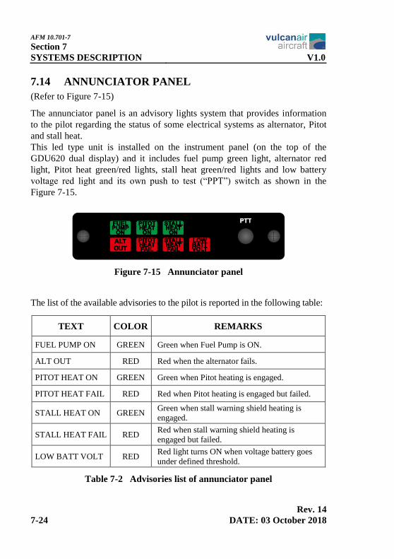
7.14 ANNUNCIATOR PANEL
(Refer to Figure 7-15)
The annunciator panel is an advisory lights system that provides information
to the pilot regarding the status of some electrical systems as alternator, Pitot
and stall heat.
This led type unit is installed on the instrument panel (on the top of the
GDU620 dual display) and it includes fuel pump green light, alternator red
light, Pitot heat green/red lights, stall heat green/red lights and low battery
voltage red light and its own push to test (“PPT”) switch as shown in the
Figure 7-15.
Figure 7-15 Annunciator panel
The list of the available advisories to the pilot is reported in the following table:
TEXT COLOR REMARKS
FUEL PUMP ON GREEN Green when Fuel Pump is ON.
ALT OUT RED Red when the alternator fails.
PITOT HEAT ON GREEN Green when Pitot heating is engaged.
PITOT HEAT FAIL RED Red when Pitot heating is engaged but failed.
STALL HEAT ON GREEN Green when stall warning shield heating is
engaged.
STALL HEAT FAIL RED Red when stall warning shield heating is
engaged but failed.
LOW BATT VOLT RED Red light turns ON when voltage battery goes
under defined threshold.
Table 7-2 Advisories list of annunciator panel

AFM 10.701-7
Section 7
V1.0 SYSTEMS DESCRIPTION
Rev. 14
DATE: 03 October 2018 7-25
7.15 STALL WARNING SYSTEM
(Refer to Figure 7-16)
The stall warning system consists of a heated stall detector (high incidence
sensor) composed of a metal vane and microswitch assembly, installed on the
outboard leading edge of the LH wing between ribs #4 and #5, and a horn
located on the LH side of the control pedestal.
The vane is exposed to the airstream during flight, and it is forced upwards by
the airflow if the aircraft approaches stall incidence.
The upward movement of the vane closes the internal microswitch, causing a
cabin-mounted warning horn to sound.
The stall detector is fitted with an integrally mounted electrical heating
element to avoid ice formation.
Both the stall warning circuit and the stall heating circuit are protected by
appropriate circuit breakers.
The stall warning circuit is powered through Main Bus Bar.
The stall heat is powered through Secondary Cut-Off Bar.
The system can be checked on the ground by switching the battery ON and
moving the wing sensor vane upwards.
Figure 7-16 Stall warning system

AFM 10.701-7
Section 7
SYSTEMS DESCRIPTION V1.0
Rev. 14
7-26 DATE: 03 October 2018
7.16 ENVIRONMENTAL SYSTEM
(Refer to Figures 7-17 and 7-18)
The Environmental System consists of the following separated sub-systems:
• Cabin Air Heating / Windshield Defrosting System
• Fresh Air System
7.16.1 CABIN AIR HEATING / WINDSHIELD DEFROSTING SYSTEM
Hot air in the cabin is provided by four air outlet vents: two for windshield
defrost installed on the instrument panel cover and two adjustable air outlet
vents installed on the lower LH/RH side of the control pedestal.
Dynamic air coming from the air inlet is mixed with the one coming from the
heat exchanger through a heater valve, installed on the RH lower FWD side of
the fuselage firewall, in order to obtain the desired temperature.
The crew can manually change the temperature of the air flow through the
regulation of the heater valve opening/closing by means of a push/pull control
knob installed on the central pedestal. With the control knob full pushed, the
heater valve is closed.
Figure 7-17 Cabin hot air controls overview
ADJUSTABLE
AIR OUTLET
VENT

AFM 10.701-7
Section 7
V1.0 SYSTEMS DESCRIPTION
Rev. 14
DATE: 03 October 2018 7-27
7.16.2 FRESH AIR SYSTEM
Fresh air in the cabin is provided by two dynamic air inlets installed on the
wing leading edge linked to four adjustable air outlet vents (two for each side)
with shut-off provision installed inside the cabin.
The crew and/or passengers can manually change the air flow through the
regulation of the air outlet vents opening/closing.
Figure 7-18 Cabin fresh air controls overview

AFM 10.701-7
Section 7
SYSTEMS DESCRIPTION V1.0
Rev. 14
7-28 DATE: 03 October 2018
7.17 PITOT AND STATIC SYSTEM
(Refer to Figure 7-19)
The Pitot-static system supplies dynamic and static air pressure for the
operation of the airspeed indicator.
The airspeed indicator receives ram air pressure through lines connected to the
Pitot tube mounted under the LH wing leading edge.
The Pitot tube is equipped with an internal electrical heating element to avoid
ice build-up that could obstruct the tube opening during severe weather
conditions.
Atmospheric pressure is provided by two static pressure ports mounted
forward the pilot/co-pilot doors on opposite sides of the fuselage.
Dedicated lines connect these ports to the Air Data Computer (ADC) and
Stand-by instrument (MD302 Standby Attitude Module).
In an emergency situation, cabin air pressure is substituted for atmospheric air
pressure by means of the alternate static source which is located on the top
side of the engine control pedestal.
Figure 7-19 Pitot and static system connections scheme

AFM 10.701-7
Section 7
V1.0 SYSTEMS DESCRIPTION
Rev. 14
DATE: 03 October 2018 7-29
7.18 DIGITAL COCKPIT
(Refer to Figures 7-20 through 7-49)
WARNING
The detailed description, operation and
functionalities of equipment manufactured by
Garmin, JPI and MidContinent are provided
on the documents listed in the NOTE below,
which are to be considered as attached to this
AFM and kept onboard the aircraft.
NOTE
For detailed description and operation of Garmin
G500 avionic system and Garmin LRUs, JPI EDM-
930 unit and MD302 Stand-by Attitude module
refer to the following documents (latest revision):
- “Garmin G500 Pilot’s Guide” p/n 190-01102-02
(for a/c installing GDU620 up to SW version 6.21)
- “Garmin G500 Pilot’s Guide” p/n 190-00601-02
(for a/c installing GDU620 from SW version 7.30
onwards)
- “Garmin GTN650 Pilot’s Guide” p/n 190-01004-03
- “Garmin GNC255 Pilot’s Guide” p/n 190-01182-01
- “Garmin GMA350 Pilot’s Guide” p/n 190-01134-12
- “MD302 Stand-by Attitude Module Pilot’s Guide”
p/n 9017846
- “JPI Engine Data Management EDM-930 Primary
TSO Pilot’s Guide” p/n 1012
7.18.1 GARMIN G500 AVIONIC SYSTEM AND GARMIN LRUS OVERVIEW
The Garmin G500 avionic system is an integrated display system that presents
primary flight instrumentation, navigation, and a moving map to the pilot
through a dual VGA 6.5 in. LCD display.
In normal operating mode, the Primary Flight Display (PFD) presents
graphical flight instrumentation (attitude, heading, airspeed, altitude, vertical
speed), while the Multi-Function Display (MFD) normally displays a full-
color moving map with navigation information.
All the components of the Garmin G500 are Line-replaceable Units (LRUs).

AFM 10.701-7
Section 7
SYSTEMS DESCRIPTION V1.0
Rev. 14
7-30 DATE: 03 October 2018
This modular approach allows to the various components to be mounted either
behind each of the displays or in remote locations in the aircraft, based upon
the needs of the aircraft manufacturer.
In addition to the Garmin G500, the aircraft configuration includes other
Garmin LRUs, interfacing with the Garmin G500, and giving to the aircraft
further functionalities as VHF communication, VOR/LOC/GS, GPS,
transponder and audio selector features.
Garmin G500 Configuration
- GDU620 (PFD/MFD)
- GDC74A (Air Data System)
- GRS77 and GMU44 (AHRS and Magnetometer)
Additional Garmin LRUs
- GMA350 (Audio Panel)
- GTX33 w/ES (Transponder ADS-B Out)
- GTN650 (NAV/COM/GPS Unit)
- GNC255B (NAV/COM Unit)
Concerning the third party’s equipment, the aircraft configuration includes:
Standby
- Digital MD302 Standby Attitude Module
Optional Equipment
- GTX345R (Transponder ADS-B In & Out)
- ADF Bendix/King KR87
- DME Bendix/King KN62A
The power plant and electrical systems are monitored by the JPI EDM-930
(Primary Engine Data Management System) that interfaces directly with the
engines and the electrical sensors and displays the data to the pilot through its
own LCD. It also provides a fuel level indication interfacing directly with the
fuel transmitters located in the aircraft wings.
The Figure 7-20 illustrates the block architecture of the Garmin G500 suite
and third party’s equipment for a typical aircraft configuration.
The Figure 7-21 illustrates the block architecture of the Garmin G500 avionic
system when the optional GTX345R Transponder is installed.

AFM 10.701-7
Section 7
V1.0 SYSTEMS DESCRIPTION
Rev. 14
DATE: 03 October 2018 7-31
Figure 7-20 Garmin G500 avionic system block architecture
Figure 7-21 Garmin G500 avionic system with optional GTX345R
HDSB
HDSB

AFM 10.701-7
Section 7
SYSTEMS DESCRIPTION V1.0
Rev. 14
7-32 DATE: 03 October 2018
7.18.2 GARMIN G500 AVIONIC SYSTEM AND GARMIN LRUS
COMPONENTS
A description of the main components of the Garmin G500 Avionic Display
System and Garmin LRUs is reported hereunder.
GDU620 Display unit PFD/MFD
GDU620 has a dual VGA (640 x 480 pixels) 6.5 inch LCD display.
The Primary Flight Display (PFD) is located on the RH side of the GDU620
while the Multifunction Display (MFD) on the LH side (with the optional
GDU unit, the PFD is located on the RH side, while the MFD is located on the
LH side).
The PFD shows primary flight information, while the MFD shows navigation
and flight plan information (traffic, weather and terrain).
GDU620 uses an external configuration module, so in case of replacement, no
reconfiguration is needed.
Figure 7-22 GDU620 Display unit PFD/MFD

AFM 10.701-7
Section 7
V1.0 SYSTEMS DESCRIPTION
Rev. 14
DATE: 03 October 2018 7-33
GDC74A Air Data Computer and GTP 59 OAT probe
GDC74A Air Data Computer is a remote mounted device that provides air
data (pressure altitude, airspeed, vertical speed) for flight instrumentation.
It receives the standard Pitot and static system inputs as well as the GTP59
outside air temperature (OAT) sensor input.
This allows the system to automatically perform calculations such as true
airspeed (TAS) and density altitude.
Figure 7-23 GDC74A Air Data Computer - GTP59 OAT probe
GRS77 Attitude Heading and Reference System and GMU44 Magnetometer
GRS77 AHRS is a remote mounted device that provides flight attitude and
heading data for flight instrumentation. It provides valid attitude, angular rate
and acceleration information to the PFD and interfaces with the GMU44
magnetometer.
GMU44 is a tri-axial magnetometer which allows the system to measure both
the horizontal and vertical components of the earth’s magnetic field.
Both GRS77 and GMU44 are solid-state components that require very little
initialization time (less than one minute).
Figure 7-24 GRS77 AHRS - GMU44 Magnetometer

AFM 10.701-7
Section 7
SYSTEMS DESCRIPTION V1.0
Rev. 14
7-34 DATE: 03 October 2018
GMA350 Audio Panel
GMA350 is a horizontally oriented panel-mounted audio controller and
marker beacon system that collects, processes and distributes audio signals
between avionics, crew and passengers.
GMA350 provides a speaker output that may be used as a cockpit speaker or
for a PA system to address passengers. GMA350 also includes a digital
recording and playback feature.
Figure 7-25 GMA350 Audio Panel
GTX33 w/ES Transponder
GTX33 Mode-S transponder is a radio transmitter and receiver with ADS-B
Out capability, that that operates on radar frequencies (receives ground radar
or TCAS interrogations and transmits a coded response of pulses to ground-
based radar).
The GTX33 Mode-S transponder is solid-state units and require no warm-up
time. This is designed to minimize pilot workload when at the threshold of the
runway. GTX33 is equipped with IDENT capability that activates the Special
Position Identification (SPI) pulse for 18 seconds.
GTX33 replies to Mode-A, Mode-C and Mode-S interrogation.
Figure 7-26 GTX33 w/ES Transponder

AFM 10.701-7
Section 7
V1.0 SYSTEMS DESCRIPTION
Rev. 14
DATE: 03 October 2018 7-35
GTN650 NAV/COM/GPS unit
GTN650 unit is a horizontal panel-mount GPS/SBAS navigator with a touch-
screen interface and color moving map.
GTN650 unit can give simultaneously, in relation to the aircraft position,
approach information and weather and traffic data.
GTN650 unit is certified for primary navigation, including operations en route
or terminal, incorrect approaches and approaches with vertical guidance.
In addition, it includes, an airborne VHF communications transceiver and
airborne VOR/Localizer (LOC) and Glideslope (G/S) receivers.
Figure 7-27 GTN650 NAV/COM/GPS unit
GNC255B NAV/COM unit
GNC255B is a horizontally oriented panel-mounted that features a number of
advanced features to save time and effort, in addition to the traditional NAV
& COMM functions.
It does not feature a GPS function, but it can interface a compatible GPS
source as GTN650.
When connected to a GPS source, the GNC255B is able to find the nearest
airport to the present position and easily access its weather, center and FSS
frequencies.
Figure 7-28 GNC255B NAV/COM unit

AFM 10.701-7
Section 7
SYSTEMS DESCRIPTION V1.0
Rev. 14
7-36 DATE: 03 October 2018
OPTIONAL EQUIPMENT:
ADF Bendix/King KR87 unit
Bendix King KR87 Automatic Direction Finder (ADF) system is a digitally
tuned solid state receiver which provides bearing information to stations in the
200 KHz to 1799 KHz frequency band and which also provides audio
reception to enable the pilot to identify stations and listen to transcribed
weather broadcasts or commercial radio stations in the AM broadcast band.
The unit features a gas discharge display that displays the active ADF
frequency in the LH window. The RH window will display either the standby
frequency (which can be transferred to the active window) or a flight timer or
programmable elapsed timer.
Figure 7-29 KR87 ADF system
DME Bendix/King KN62A unit
Bendix King KN62A DME system is a panel mounted, 200 channel DME
employing the latest state of the art solid state transmitter and large scale
integrated circuit (LSI) technology. All tuning is done electronically using a
single crystal, digital, frequency synthesizer.
The unit features a gas discharge display that simultaneously indicates range,
speed and time to station or range and frequency.
Figure 7-30 KN62A DME system
AFM 10.701-7
Section 7
V1.0 SYSTEMS DESCRIPTION
Rev. 14
DATE: 03 October 2018 7-37
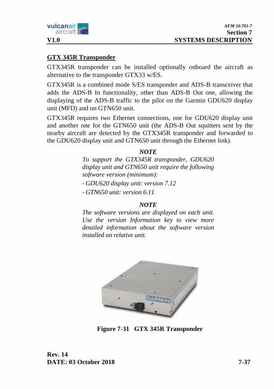
GTX 345R Transponder
GTX345R transponder can be installed optionally onboard the aircraft as
alternative to the transponder GTX33 w/ES.
GTX345R is a combined mode S/ES transponder and ADS-B transceiver that
adds the ADS-B In functionality, other than ADS-B Out one, allowing the
displaying of the ADS-B traffic to the pilot on the Garmin GDU620 display
unit (MFD) and on GTN650 unit.
GTX345R requires two Ethernet connections, one for GDU620 display unit
and another one for the GTN650 unit (the ADS-B Out squitters sent by the
nearby aircraft are detected by the GTX345R transponder and forwarded to
the GDU620 display unit and GTN650 unit through the Ethernet link).
NOTE
To support the GTX345R transponder, GDU620
display unit and GTN650 unit require the following
software version (minimum):
- GDU620 display unit: version 7.12
- GTN650 unit: version 6.11
NOTE
The software versions are displayed on each unit.
Use the version Information key to view more
detailed information about the software version
installed on relative unit.
Figure 7-31 GTX 345R Transponder

AFM 10.701-7
Section 7
SYSTEMS DESCRIPTION V1.0
Rev. 14
7-38 DATE: 03 October 2018
7.18.3 GARMIN G500 AVIONIC SYSTEM AND GARMIN LRUS CONTROLS
Controls are located on the GDU620 display unit (PFD/MFD), GMA350
audio panel, GTN650 NAV/COM/GPS unit and GNC255B NAV/COM unit.
GDU620 display unit (PFD/MFD) controls
Functions on the PFD are accessed by using the bezel keys on the side of the
PFD and the softkeys below the PFD.
Figure 7-32 PFD description (Ground Pointer Mode)
Figure 7-33 PFD Nav Status Bar description

AFM 10.701-7
Section 7
V1.0 SYSTEMS DESCRIPTION
Rev. 14
DATE: 03 October 2018 7-39
Functions on the MFD are accessed by using the bezel keys on the side of the
MFD and the softkeys below the MFD.
Figure 7-34 MFD description
PFD AND MFD SOFTKEYS FUNCTION
The softkeys are located along the bottoms of the displays. The softkeys labels
shown depend on the softkey level or page being displayed.
The bezel keys below the softkeys can be used to select the appropriate softkey.
When a softkey is selected, its color changes to black text on gray background and
remains this way until it is turned off, at which time it reverts to white text on black
background. When a softkey function is disabled, the softkey label is subdued
(dimmed). Softkeys revert to the previous level after 45 seconds of inactivity.
Each softkey sublevel has a BACK softkey which can be pressed to return to
the previous level.
Figure 7-35 PFD softkeys layout

AFM 10.701-7
Section 7
SYSTEMS DESCRIPTION V1.0
Rev. 14
7-40 DATE: 03 October 2018
Figure 7-36 PFD softkeys diagram
Figure 7-37 MFD softkeys layout
Figure 7-38 MFD softkeys diagram

AFM 10.701-7
Section 7
V1.0 SYSTEMS DESCRIPTION
Rev. 14
DATE: 03 October 2018 7-41
GMA350 audio panel controls
GMA350 audio panel controls are shown in the Figure 7-39 below.
Figure 7-39 Audio panel controls

AFM 10.701-7
Section 7
SYSTEMS DESCRIPTION V1.0
Rev. 14
7-42 DATE: 03 October 2018
GTN650 NAV/COM/GPS unit controls
GTN650 NAV/COM/GPS unit controls are designed to simplify operation of
the system and minimize workload and the time required to access
sophisticated functionality.
Controls are located on the bezel and on the touchscreen display.
Controls are comprised of dual concentric knobs, volume/squelch knob, bezel
keys, and active touch areas on the display.
Touchscreen keys are placed around the display. The keys vary depending on
the page selected. Touch the key to perform the function or access the
described information.
Figure 7-40 GTN650 NAV/COM/GPS unit description
Figure 7-41 GTN650 touchscreen key controls (Home page)

AFM 10.701-7
Section 7
V1.0 SYSTEMS DESCRIPTION
Rev. 14
DATE: 03 October 2018 7-43
GNC255B NAV/COM unit controls
GNC255B NAV/COM unit controls are designed to simplify systems operation,
minimize workload, and reduce time required to access functionality.
Controls are comprised of dual concentric knobs for frequency tuning, COM
volume/squelch knob, NAV volume/ID knob, and bezel keys.
Figure 7-42 GNC255B NAV/COM unit description and controls

AFM 10.701-7
Section 7
SYSTEMS DESCRIPTION V1.0
Rev. 14
7-44 DATE: 03 October 2018
7.18.4 MD302 STANDBY ATTITUDE MODULE
MD302 Standby Attitude Module is a self-contained situational awareness
instrument that provides aircraft attitude, altitude, airspeed and slip indication
during normal operation or in case of primary instrument failure.
This instrument is installed horizontally in the top central area of the
instrument panel (for all aircraft except s/n 1002) or vertically on the LH side
of the Garmin GDU620 dual display (only for aircraft s/n 1002).
WARNING
All MD302 Standby Attitude Module settings,
set up during the aircraft delivery or after a
maintenance activity, must not be modified.
WARNING
Heading function of the MD302 Standby
Attitude Module must not be enabled.
Figure 7-43 MD302 Standby Attitude Module

AFM 10.701-7
Section 7
V1.0 SYSTEMS DESCRIPTION
Rev. 14
DATE: 03 October 2018 7-45
7.18.5 EDM-930 ENGINE DATA MANAGEMENT SYSTEM
EDM-930 is a combined electronic indicating system that interfaces directly
with the engine and the electrical sensors and displays simultaneously to the
pilot, through its own LCD, the power plant and the aircraft systems operating
parameters.
EDM-930 includes a Remote Alarm Display (RAD) that is a 0.2” high, 8
characters independent display, located on the top of GDU620 display unit;
the RAD displays digital cautions and limit exceedances when some
parameters have reached its pre-set trigger point.
An alarm is activated as soon one parameter exceeds its operating range.
Figure 7-44 EDM-930 System - RAD unit
EDM-930 Engine Data Management System controls
Functions on EDM-930 system are accessed by using the four operating
buttons on the lower side of the EDM (these buttons could change labels
depending on the current operating mode of the EDM).
The EDM-930 Engine Data Management System controls are shown in the
following Figure 7-45.
The term “tap” is used to denote pressing a button momentarily, while the
term “hold” is used to denote pressing and holding a button for five or more
seconds.

AFM 10.701-7
Section 7
SYSTEMS DESCRIPTION V1.0
Rev. 14
7-46 DATE: 03 October 2018
Figure 7-45 EDM-930 system controls

AFM 10.701-7
Section 7
V1.0 SYSTEMS DESCRIPTION
Rev. 14
DATE: 03 October 2018 7-47
7.18.6 ENGINE INDICATION SYSTEM (EIS)
The engine parameters and their ranges for the Vulcanair V1.0 aircraft are
reported in the following table:
Parameter Units Range Low
Red
Low
Yellow Green
Upper
Yellow
High
Red
Warning Caution Normal Caution Warning
Tachometer RPM 550 ÷ 2800 550 ÷ 2700 2700
Man. Pres. In Hg A 10 ÷ 40 10 ÷ 32
Oil Pres. PSIG 0 ÷ 100 25 25 ÷ 55 55 ÷ 95 95
Oil Temp. °F 32 ÷ 260 75 ÷ 224 225 ÷ 245 245
Fuel Flow Gal/hr 0.6 ÷ 40 0 ÷ 20
Fuel Pres. PSIG 0 ÷ 50 14 14 ÷ 35 35
EGT °F 32 ÷ 1800 1180 ÷ 1380
CHT °F 32 ÷ 600 200 ÷ 475 475 ÷ 500 500
Table 7-3 Engine parameters
AFM 10.701-7
Section 7
SYSTEMS DESCRIPTION V1.0
Rev. 15
7-48 DATE: 21 December 2018
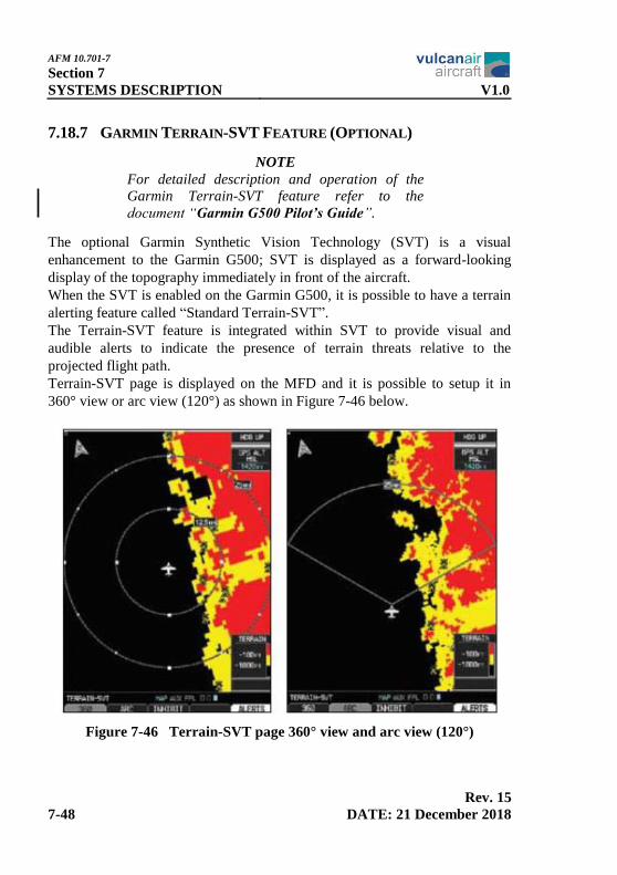
7.18.7 GARMIN TERRAIN-SVT FEATURE (OPTIONAL)
NOTE
For detailed description and operation of the
Garmin Terrain-SVT feature refer to the
document “Garmin G500 Pilot’s Guide”.
The optional Garmin Synthetic Vision Technology (SVT) is a visual
enhancement to the Garmin G500; SVT is displayed as a forward-looking
display of the topography immediately in front of the aircraft.
When the SVT is enabled on the Garmin G500, it is possible to have a terrain
alerting feature called “Standard Terrain-SVT”.
The Terrain-SVT feature is integrated within SVT to provide visual and
audible alerts to indicate the presence of terrain threats relative to the
projected flight path.
Terrain-SVT page is displayed on the MFD and it is possible to setup it in
360° view or arc view (120°) as shown in Figure 7-46 below.
Figure 7-46 Terrain-SVT page 360° view and arc view (120°)
AFM 10.701-7
Section 7
V1.0 SYSTEMS DESCRIPTION
Rev. 14
DATE: 03 October 2018 7-49
WARNING
Do not use Terrain-SVT information for
primary terrain avoidance. Terrain-SVT is
intended only to enhance situational awareness.
NOTE
Terrain data is not displayed when the aircraft is
outside of the terrain database coverage area.
NOTE
Terrain-SVT is provided with the Garmin
Synthetic Vision Technology (SVT) functionality
and not marketed separately.
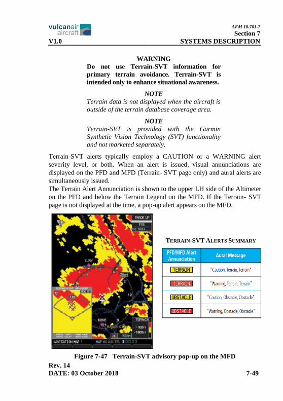
Terrain-SVT alerts typically employ a CAUTION or a WARNING alert
severity level, or both. When an alert is issued, visual annunciations are
displayed on the PFD and MFD (Terrain- SVT page only) and aural alerts are
simultaneously issued.
The Terrain Alert Annunciation is shown to the upper LH side of the Altimeter
on the PFD and below the Terrain Legend on the MFD. If the Terrain- SVT
page is not displayed at the time, a pop-up alert appears on the MFD.
Figure 7-47 Terrain-SVT advisory pop-up on the MFD
TERRAIN-SVT ALERTS SUMMARY

AFM 10.701-7
Section 7
SYSTEMS DESCRIPTION V1.0
Rev. 14
7-50 DATE: 03 October 2018
7.18.8 TRANSPONDER ADS-B IN TRAFFIC FEATURE (OPTIONAL)
NOTE
For detailed description and operation of the
Garmin ADS-B IN Traffic feature refer to
documents “Garmin G500 Pilot’s Guide” p/n
190-00601-02 and “Garmin GTN650 Pilot’s
Guide” p/n 190-01004-03” latest revision.
NOTE
To support the transponder ADS-B IN capability,
GTX345R transponder must be installed onboard
the aircraft, and GDU620 display unit and
GTN650 unit require the following software
version (minimum):
- GDU620 display unit: version 7.12
- GTN650 unit: version 6.11
The optional Garmin ADS-B IN Traffic feature allows a properly-equipped
aircraft to receive TIS-B (Traffic Information Service - Broadcast) and FIS-B
(Flight Information Services - Broadcast) weather from ground stations and
other aircraft equipped with ADS-B OUT capability.
ADS-B IN Traffic targets can be displayed both in air and on ground.
On the GTN650 unit the ADS-B IN Traffic is displayed on the dedicate traffic
page selected by touching the traffic icon on the display (“Traffic Menu” page
will appear). Touching ADS-B display icon toggles the display of ADS-B
Traffic and ADS-B Traffic alerting.
Traffic targets displayed on the dedicated traffic page may be selected in order
to obtain additional information about a traffic target or to view all targets in a
grouped target. When a grouped target is selected, the Next key on the
dedicated traffic page will cycle through all targets located in close proximity
to where the screen has been touched.

AFM 10.701-7
Section 7
V1.0 SYSTEMS DESCRIPTION
Rev. 14
DATE: 03 October 2018 7-51
Figure 7-48 ADS-B Traffic page on GTN650 unit
On GDU620 display unit the ADS-B IN traffic can be display in the traffic
page of the MFD. This page will be entered rotating the large knob to select
the “MAP PAGE GROUP” and then selecting, through the softkey or turning
the inner knob, the ADS-B Traffic Map Page.
The Traffic Map Page shows surrounding TIS traffic data in relation to the
aircraft’s current position and altitude. The Traffic option is designed to assist
in detection and avoidance of other aircraft.
Traffic targets displayed on the dedicated traffic page may be selected in order
to obtain additional information about a traffic target.
Figure 7-49 ADS-B Traffic Map page on GDU 620 display unit
AFM 10.701-7
Section 7
SYSTEMS DESCRIPTION V1.0
Rev. 14
7-52 DATE: 03 October 2018
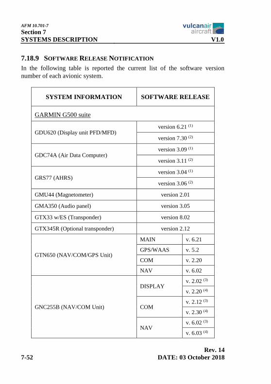
7.18.9 SOFTWARE RELEASE NOTIFICATION
In the following table is reported the current list of the software version
number of each avionic system.
SYSTEM INFORMATION SOFTWARE RELEASE
GARMIN G500 suite
GDU620 (Display unit PFD/MFD) version 6.21 (1)
version 7.30 (2)
GDC74A (Air Data Computer) version 3.09 (1)
version 3.11 (2)
GRS77 (AHRS) version 3.04 (1)
version 3.06 (2)
GMU44 (Magnetometer) version 2.01
GMA350 (Audio panel) version 3.05
GTX33 w/ES (Transponder) version 8.02
GTX345R (Optional transponder) version 2.12
GTN650 (NAV/COM/GPS Unit)
MAIN v. 6.21
GPS/WAAS v. 5.2
COM v. 2.20
NAV v. 6.02
GNC255B (NAV/COM Unit)
DISPLAY v. 2.02 (3)
v. 2.20 (4)
COM v. 2.12 (3)
v. 2.30 (4)
NAV v. 6.02 (3)
v. 6.03 (4)

AFM 10.701-7
Section 7
V1.0 SYSTEMS DESCRIPTION
Rev. 14
DATE: 03 October 2018 7-53
Standby instrument
MD302
version 1.0.5 (5)
version 1.1.0 (6)
version 1.1.1 (2)
Engine Data Management
EDM-930 version 1.20.489
(1) Valid for V1.0 aircraft from s/n 1001 up to s/n 1008.
(2) Valid for V1.0 aircraft from s/n 1009 onwards.
(3) Valid for V1.0 aircraft s/n 1001 and 1002.
(4) Valid for V1.0 aircraft from s/n 1003 onwards.
(5) Valid for V1.0 aircraft from s/n 1002 up to s/n 1008.
(6) Valid for V1.0 aircraft s/n 1001.
Table 7-4 Software release notification
WARNING
In case of replacement of one of the previous
avionic units, verify proper software load and
confirm that its software version number is in
compliance with that one showed in table
above, before installing it.
NOTE
The software versions are displayed on each unit.
Use the version Information key to view more
detailed information about the software version
installed on relative unit.
This information is useful when contacting
Customer Support.

AFM 10.701-7
Section 7
SYSTEMS DESCRIPTION V1.0
Rev. 15
7-54 DATE: 21 December 2018
7.19 PLACARDS
A list of placards not inserted in Section 2 of this Aircraft Flight Manual are
reported below.
On the top side of the MLG wheel fairings:
On the LH/RH sides of the fuselage nose, near static ports:
Outside LH crew door, near door handle:
Outside RH crew door and passenger door, near door handle:
Inside LH crew door, near door handle:

AFM 10.701-7
Section 7
V1.0 SYSTEMS DESCRIPTION
Rev. 15
DATE: 21 December 2018 7-55
Inside RH crew door and passenger door, near door handle:
Inside LH crew door, near door interlock mechanism:
Inside RH crew door and passenger door, near door interlock mechanism:

AFM 10.701-7
Section 7
SYSTEMS DESCRIPTION V1.0
Rev. 15
7-56 DATE: 21 December 2018
Inside the cabin, passenger area LH side
Only for aircraft s/n 1002
For aircraft from s/n 1003 onwards, plus s/n 1001
AFM 10.701-7
Section 7
V1.0 SYSTEMS DESCRIPTION
Rev. 15
DATE: 21 December 2018 7-57
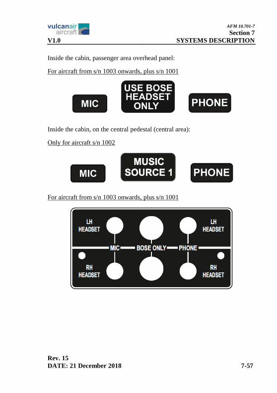
Inside the cabin, passenger area overhead panel:
For aircraft from s/n 1003 onwards, plus s/n 1001
Inside the cabin, on the central pedestal (central area):
Only for aircraft s/n 1002
For aircraft from s/n 1003 onwards, plus s/n 1001

AFM 10.701-7
Section 7
SYSTEMS DESCRIPTION V1.0
Rev. 15
7-58 DATE: 21 December 2018
Inside the cabin, on the central pedestal (lower area):
Only for aircraft s/n 1001
For aircraft from s/n 1002 onwards
For aircraft from s/n 1003 onwards, plus s/n 1001
Inside the cabin, on the instrument panel LH side (glove compartment):
For aircraft from s/n 1003 onwards, plus s/n 1001

AFM 10.701-7
Section 7
V1.0 SYSTEMS DESCRIPTION
Rev. 15
DATE: 21 December 2018 7-59
On the first aid box:
Inside the first aid box:

AFM 10.701-7
Section 7
SYSTEMS DESCRIPTION V1.0
Rev. 15
7-60 DATE: 21 December 2018
Inside the first aid box (small type):