section 1 overview - hvac usa · section 1 overview introduction 1-1 the siemens lmv5 burner /...
TRANSCRIPT

LMV Quick Start Guide Rev 2 Page 1 Section 1
Section 1 Overview Introduction 1-1 The Siemens LMV5 Burner / Boiler Management System (BMS) combines the functionalities of a flame safeguard and a fuel-air ratio control when it is used in it’s most simple form. This BMS is modular, and can be expanded to encompass features such as load control, integrated O2 trim, Differential Pressure (DP) based feedwater control, Variable Speed Drive (VSD), fuel usage monitoring, efficiency monitoring, simultaneous operation of 5 rotary actuators, Lead / Lag control, Touch Screen Human Machine Interfaces (HMI), ModBUS communications and other advanced features. These features make the LMV5 extremely flexible, and ideally suited for use with most steam boilers, hot water boilers, thermal fluid heaters, and industrial burners.
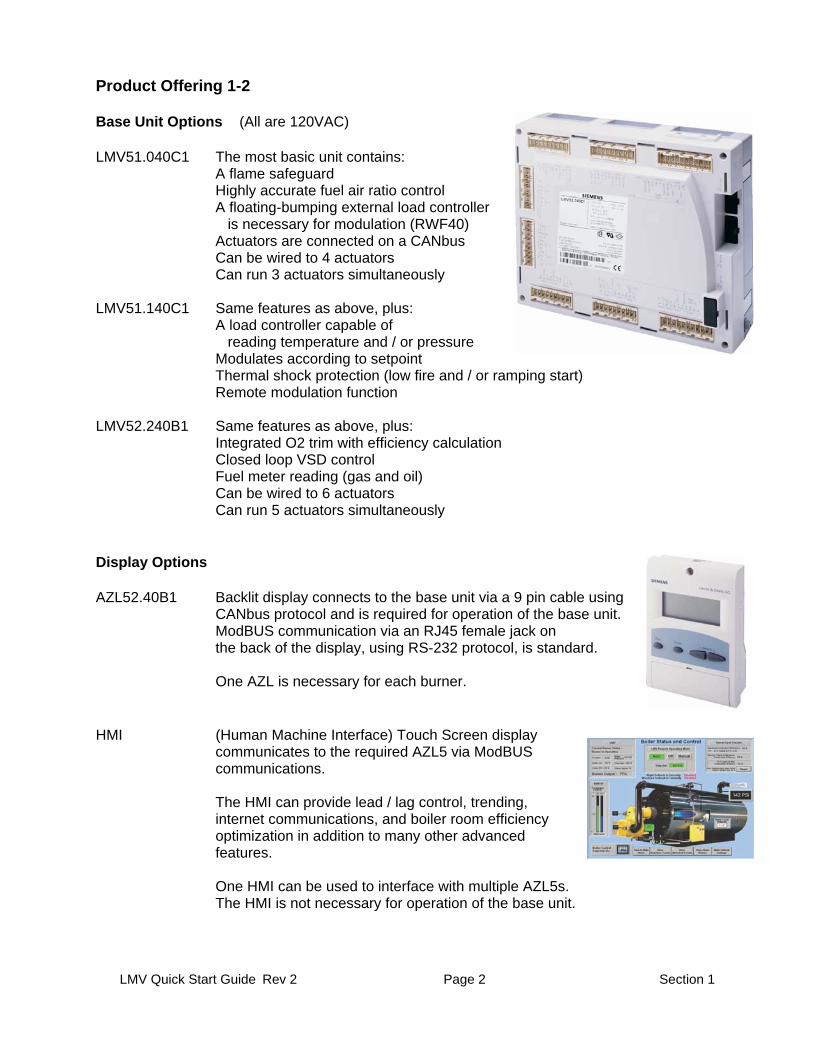
Figure 1-1.1 Typical LMV5 Base Unit
LMV Quick Start Guide Rev 2 Page 2 Section 1
Product Offering 1-2 Base Unit Options (All are 120VAC) LMV51.040C1 The most basic unit contains:
A flame safeguard Highly accurate fuel air ratio control A floating-bumping external load controller is necessary for modulation (RWF40) Actuators are connected on a CANbus Can be wired to 4 actuators Can run 3 actuators simultaneously
LMV51.140C1 Same features as above, plus:
A load controller capable of reading temperature and / or pressure Modulates according to setpoint Thermal shock protection (low fire and / or ramping start) Remote modulation function
LMV52.240B1 Same features as above, plus:
Integrated O2 trim with efficiency calculation Closed loop VSD control Fuel meter reading (gas and oil) Can be wired to 6 actuators Can run 5 actuators simultaneously
Display Options AZL52.40B1 Backlit display connects to the base unit via a 9 pin cable using
CANbus protocol and is required for operation of the base unit. ModBUS communication via an RJ45 female jack on the back of the display, using RS-232 protocol, is standard.
One AZL is necessary for each burner.
HMI (Human Machine Interface) Touch Screen display
communicates to the required AZL5 via ModBUS communications.
The HMI can provide lead / lag control, trending,
internet communications, and boiler room efficiency optimization in addition to many other advanced features.
One HMI can be used to interface with multiple AZL5s. The HMI is not necessary for operation of the base unit.

LMV Quick Start Guide Rev 2 Page 3 Section 1
Actuator Options SQM45.295A9 27 in / lb of torque 10-120 seconds 10 mm “D” shaped shaft SQM48.497A9 177 in / lb of torque 30-120 seconds 14 mm round keyed shaft SQM48.697A9 310 in / lb of torque 60-120 seconds 14 mm round keyed shaft
Note: All actuators offer:
The same case size Identical actuator mounting holes Have a 90 degree operating range Positioning accuracy of 0.1 degree Rotate either clockwise or counterclockwise
Inquire about Actuator brackets and zero lash flexible actuator shaft TAK and Ruland couplings are available and highly recommended to part numbers ensure trouble-free operation. Flame Detector Options and Accessories QRI2A2.B180B Sensor is self checking, forward viewing
(IR) detector (continuous use) AGG2.110 3/4" threaded holder for QRI2A2. B180B forward
viewing scanner having an insulated, protective lens
QRI2B2.B180B Sensor is self checking, side viewing
(IR) detector (continuous use) AGG2.120 Conduit connection adapter for QRI 3/4" NPSM thread 5002-01 Self checking forward viewing Ultra Violet (UV)
flame detector (designed for continuous use) 5002-01NC-120V Non-self checking forward viewing UV flame detector 5000-02/5 5 feet of premade cable for either of the UV detectors 5000-02/10 10 feet of premade cable for either of the UV detectors Note: All of the above flame detectors are wired directly to
the LMV5 and utilize integral flame signal amplifiers.

LMV Quick Start Guide Rev 2 Page 4 Section 1
Temperature / Pressure Sensor Options
7MF1564 Covers pressures up to 300 PSIG Output signals of 4-20 mA or 0-10 VDC Sensor connection is male 1/4” NPT
PSIG 4-20 mA 0-10 VDC 0-15 7MF15644 BB0 03EA1 7MF15644 BB1 03EA1 0-30 7MF15644 BE0 03EA1 7MF15644 BE1 03EA1 0-60 7MF15644 BF0 03EA1 7MF15644 BF1 03EA1 0-150 7MF15644 CA0 03EA1 7MF15644 CA1 03EA1 0-200 7MF15644 CB0 03EA1 7MF15644 CB1 03EA1 0-300 7MF15644 CD0 03EA1 7MF15644 CD1 03EA1
QAE2020.005 Two wire Nickel 1000 Ohm RTD immersion temperature
sensor, includes thermowell and 3” wire leads. Can also be used for ambient temperature. Operating Range is -13 to 266 oF (Replaces 556-541)
QAC22 Two wire Nickel 1000 Ohm RTD sensor for ambient
temperature. Operating Range is -20 to 125 oF Stack Sensor Recommend: Pyromation # RBF195M482-010-00-8HN31
1000 ohm 2 wire platnium RTD with weather head Needed for stack alarm and efficiency calculations Range -40 to 900 oF Temp Sensor Recommend: Pyromation # R1T185M483-004-00-6HN31-SL
100 ohm 3 wire platnium RTD spring loaded w/ weather head Thermowell, Stainless Steel, Pyromation # SD0408 Needed for temperature based cold start Range -40 to 900 oF
Note: These sensors can be directly wired to an LMV5
provided it has an internal load controller (at least LMV51.140).
Oxygen Trim Accessories (LMV52)
PLL52.110A100 O2 Module, CANbus module that is necessary to connect the flue (stack) mounted O2 sensor (QGO20) to the LMV52. Sensors for flue temperature and ambient temperature, when used, are also wired to this module.
Note : In most cases, a second transformer will be necessary when using the O2
module.
QGO20.000D17 Internally heated Zirconium Dioxide Oxygen sensor that is mounted into the flue. 575oF max flue gas temp. (Measures the wet Oxygen content in the flue.)
Stainless Steel Flue Gas Collector AGO20.001A 7-1/4" long for stack diameters up to 16” AGO20.002A 10-1/2" long for stack diameters larger than 16”

LMV Quick Start Guide Rev 2 Page 5 Section 1
Variable Speed Drive (VSD) Accessories (LMV52)
AGG5.310 VSD kit includes a speed wheel and sensor, which mounts to a blower motor for the closed loop VSD. (One kit is required)
Note : The sensor wheel normally mounts to the motor
cooling fan on the back of the blower motor This kit is much more difficult to use on motors that do not have a rear mounted cooling fan
General Accessories
AGG5.210 120 VAC to 12VAC Transformer At least one transformer is required on each BMS Additional transformers may be necessary depending on the number of actuator / modules connected to the CANbus
AGG5.643 Special cable for use with the CANbus
connections between the LMV5, actuators, and PLL52 module, supplied in a 500’ roll
AGG5.635 A pre-made cable approximately 9 ft
for connecting the AZL to the LMV5
AGG5.110 CANbus strain relief. If AZL cable AGG5.635 is used only one is required.
AGG5.720 Base plug kit
AGG5.721 Extension Plug kit Inquire about p/n Cord grip, (2) Req per Actuator, PG11- CANbus cable Inquire about p/n Cord grip, (6) Req per PLL52, M16 - CANbus cable 544-023 Conduit adapter, (2) Req per Actuator, PG11-1/2” NPSM Inquire about p/n Conduit adapter, (6) Req per PLL52, M16 -1/2” NPSM
LMV Quick Start Guide Rev 2 Page 6 Section 1
Typical BMS system 1-3
Typical LMV51 BMS System A typical LMV51 BMS system will include the following components : LMV51.140xx Basic unit with load controller AZL52.xxxx Display SQM4x Actuator for Gas metering valve SQM4x Actuator for Oil metering valve SQM4x Actuator for Air damper SQM4x Actuator for FGR (if equipped) AGG5.210 Transformer (See CANbus Loading table, Section 3, Figure 3-1.2) QRI2A2.B180B Forward viewing IR flame scanner AGG2.110 Flame scanner adapter AGG2.120 Conduit connector Temperature Sensor and /or Pressure Sensor (both can be used for cold start) AGG5.643 CANbus cable AGG5.110 CANbus strain relief AGG5.720 RAST 5 plug kit AGG5.635 Pre-made CANbus cable for AZL Flexible zero lash actuator shaft couplings (TAK or Ruland) Actuator mounting brackets (TAK) Cord grips or liquid tight conduit adapters
Typical LMV52 BMS System A typical LMV52 BMS system will include all of the components of the LMV51 system with the exception of the LMV51.140 base unit. The LMV52 unit can be used the same as a LMV51 BMS system is used, with the additional features disabled. If the additional features are utilized, additional components typically include: LMV52.240xx LMV52 required for O2 Trim or VSD (Replaces the LMV51.140) O2 Trim: PLL52.110A100 O2 trim module QGO20.000D17 O2 Sensor Depending on flue size: AGO20.001A Flue Gas Collector (up to 16” Dia) AGO20.002A Flue Gas Collector (over 16” Dia) Flue Gas (Stack) PT-1000 sensor, Pyromation RBF195M482-010-00-8HN31 QAC22 Ambient temperature sensor VSD: VSD unit (supplied separately) AGG5.310 Closed loop VSD control kit (speed wheel and sensor AGG5.210 Transformer (See CANbus Loading table, Section 3, Figure 3-1.2) SQM4x Actuators for additional valves / dampers AGG5.721 Extension Plug kit (VSD, additional actuators, transformer, etc.)
LMV Quick Start Guide Rev 2 Page 7 Section 1
Important Safety Notes 1 - 4
The LMV5 is a safety device. Under no circumstances should the unit be modified or opened. Siemens Building Technologies, Inc. will not assume responsibility for damage resulting from unauthorized modification of the unit. After commissioning, and after each service visit, the flue gas values should be checked across the firing range. All activities (mounting, installation, service work. etc.) must be performed by qualified staff. Before performing any work in the connection area of the LMV5, disconnect the unit from the main supply (all-polar disconnection). Protection against electrical shock hazard on the LMV5, and on all connected electrical components must be ensured through good wiring and grounding practices. Fall or shock can adversely affect the safety functions of an LMV5. Such units must not be put into operation, even if they do not exhibit any apparent damage. When the LMV5 is running in automatic mode, actuators are continuously monitored by the LMV5. During commissioning, when the ratio-control curves are being set, the actuator positions are NOT continuously monitored by the LMV5. The technician is solely responsible for verifying the correct position of each actuator during the ratio-control curve commissioning. The coupling that is used between the actuator and the driven valve / damper is safety related, and must be of a robust and flexible design. Should this coupling fail during operation, the LMV5 will no longer have control of the burner’s combustion bringing about a hazardous condition. Condensation and the entry of water into the unit must be avoided.
LMV Quick Start Guide Rev 2 Page 8 Section 1
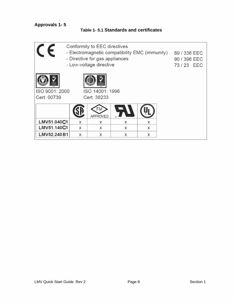
Approvals 1- 5 Table 1- 5.1 Standards and certificates