pc software for burner management system ™ pc software for burner management system lmv5......
TRANSCRIPT

ACS450®™
PC Software for Burner Management System LMV5... Operating Instructions
For software AZL5... version V340 or higher CC1J7550en 15.08.2006
Building TechnologiesHVAC Products

2/64
Building Technologies PC Software for Burner Management System LMV5... CC1J7550en HVAC Products Contents 15.08.2006

Contents
1 Introduction......................................................................................................7
1.1 Overview..........................................................................................................7 1.2 Scope of delivery .............................................................................................7
2 Typographical conventions..............................................................................8
2.1 Safety guidelines .............................................................................................8 2.2 Special note.....................................................................................................9 2.3 Correct system parameter settings..................................................................9 2.4 Setting the electronic fuel / air ratio control system........................................9 2.5 Changing the parameters and the plant configuration....................................9 2.6 Shutdown function of the LMV5... basic unit via the ACS450 ......................10
3 License and liability regulations.....................................................................11
4 System specification......................................................................................14
5 Handling and storage ....................................................................................14
5.1 Notes on handling the CD .............................................................................14
6 Languages.....................................................................................................14
7 Installation .....................................................................................................15
7.1 Installing the hardware ..................................................................................15 7.2 Installing the software....................................................................................16 7.2.1 Settings under Windows................................................................................16 7.2.2 Installing the ACS450 ....................................................................................16 7.2.3 Deinstalling / repairing ...................................................................................16 7.2.4 Disposal.........................................................................................................16 7.3 Files included in the scope of delivery...........................................................17 7.4 Generated files ..............................................................................................18
8 The first steps ................................................................................................19
8.1 Program registration ......................................................................................19 8.2 Operation of the ACS450 in connection with the LMV5… system ...............20 8.3 Closing the program ......................................................................................21 8.4 ACS450 in offline mode.................................................................................21
9 General operating functions ..........................................................................22
9.1 Scope of functions .........................................................................................22 9.2 Title bar..........................................................................................................22 9.3 Operating mode.............................................................................................23 9.3.1 Operation of the ACS450 on the plant...........................................................23
3/64
Building Technologies PC Software for Burner Management System LMV5... CC1J7550en HVAC Products Contents 15.08.2006

9.4 Password .......................................................................................................24 9.4.1 Overview........................................................................................................24 9.4.2 Entering the password ...................................................................................24 9.4.3 Changing and leaving the password level .....................................................25 9.5 Normal operation ...........................................................................................26 9.6 Fault status ....................................................................................................27 9.7 Parameter settings and configuration ............................................................28 9.7.1 Introduction ....................................................................................................28 9.7.2 Procedure ......................................................................................................28 9.8 Backup / restoring the data sets ....................................................................32 9.8.1 Backup the AZL5... ........................................................................................32 9.8.2 Restore ..........................................................................................................32 9.8.3 Backup / Restore via PC................................................................................33 9.9 Resetting / initializing the basic unit ...............................................................36 9.9.1 Resetting the basic unit..................................................................................36 9.9.2 Initializing the basic unit .................................................................................37 9.10 Switch-off function (manual locking of the basic unit LMV5...)......................37 9.11 Adjusting the fuel / air ratio control system ....................................................38 9.11.1 Modulating operation .....................................................................................38 9.11.2 Multistage operation.......................................................................................45 9.12 O2 setting.......................................................................................................46 9.12.1 Setting the O2 min values..............................................................................46 9.12.2 Setting the O2 ratio values.............................................................................47 9.12.3 Leaving the O2 setting ...................................................................................47 9.12.4 Tabular display...............................................................................................47 9.12.5 Printing...........................................................................................................48 9.13 Fault history and lockout history ....................................................................48 9.13.1 Fault history ...................................................................................................48 9.13.2 Lockout history...............................................................................................48 9.14 Time of day and date .....................................................................................48 9.15 Trending / write function.................................................................................49 9.15.1 Overview........................................................................................................49 9.15.2 Calling up the trending function .....................................................................49 9.15.3 The trending window......................................................................................50 9.15.4 Display of a channel.......................................................................................50 9.15.5 «Display» settings..........................................................................................51 9.15.6 Printing...........................................................................................................51 9.15.7 Setting the interval .........................................................................................51 9.15.8 Triggering.......................................................................................................52 9.15.9 «Status» display.............................................................................................52 9.15.10 Full screen .....................................................................................................53 9.15.11 Name of measurement ..................................................................................53
4/64
Building Technologies PC Software for Burner Management System LMV5... CC1J7550en HVAC Products Contents 15.08.2006

9.16 Program update AZL5... ................................................................................54 9.16.1 Introduction....................................................................................................54 9.16.2 Preparing the AZL5... ....................................................................................54 9.16.3 Preparing the ACS450...................................................................................54 9.16.4 Programming process ...................................................................................54 9.16.5 End of the programming process - check......................................................55
10 Offline mode ..................................................................................................56
10.1 Overview........................................................................................................56 10.2 Preparation for the display of parameters .....................................................56 10.2.1 Via the «Disconnect» menu...........................................................................56 10.2.2 Via the «Backup Database» menu ................................................................56 10.3 Calling up the parameter display ...................................................................57 10.4 Control file for displaying and printing parameters .......................................58 10.4.1 Main section of file.........................................................................................58 10.4.2 Print section...................................................................................................59 10.5 Trending / show write function.......................................................................61 10.5.1 Overview........................................................................................................61 10.5.2 Selecting the database ..................................................................................61 10.5.3 Main dialog «Trending» .................................................................................62
11 Online help ....................................................................................................63
12 Fault handling ................................................................................................63
12.1 Faults during the parameter setting procedure.............................................63 12.2 Faults when opening a connection ................................................................63
5/64
Building Technologies PC Software for Burner Management System LMV5... CC1J7550en HVAC Products Contents 15.08.2006

6/64
Building Technologies PC Software for Burner Management System LMV5... CC1J7550en HVAC Products Contents 15.08.2006
1 Introduction 1.1 Overview The ACS450 is a PC-based operating program for use with the LMV5... burner man-agement system. The requirements placed on the relevant PC are specified in chapter 4. The PC must be connected directly to the AZL5... display and operating unit via a serial port. The ACS450 operating software provides the following key functions: • Readout of settings, operating states and kinds of faults of the LMV5... system as
well as the time of day the faults occurred • Graphic support when setting the electronic fuel / air ratio control system • Setting the parameters of the LMV5... system • Trend recording (write function) • Printout functions for documenting the plant settings • Program update AZL5... All key data can be filed in databases and viewed later without necessarily having to use the LMV5... system. The different parameter setting levels for the burner / boiler manufacturer and the heat-ing engineer are password-protected to prevent unauthorized access. The basic settings that can be made on site by the plant operator do not require a password. Operation of the program is mainly based on Windows standards and demands basic PC knowledge. If desired, Windows’ online help system can be used. It can be retrieved via the standard menu.
1.2 Scope of delivery The operating software is supplied on a CD. In case of loss, a replacement CD can be ordered under type reference ACS450. The connecting cable for linking the AZL5... display and operating unit to the PC is not included in the delivery. The required cable is specified in section «Installing the hardware». The CD contains the following files:
• InstMsiA.exe Installation programs • InstMsiW.exe • Setup.exe • Setup.ini • Acs450.msi Installation data • Manual_D.pdf Program documentation in German • Manua_E.pdf Program documentation in English • Version.txt Program version number
7/64
Building Technologies PC Software for Burner Management System LMV5... CC1J7550en HVAC Products 1 Introduction 15.08.2006

2 Typographical conventions 2.1 Safety guidelines This manual contains notes which you should observe to ensure your own personal safety and to protect the product and connected equipment. These notes are high-lighted in the manual by a warning triangle, arrow or hand and are marked as follows according to the level of danger:
Danger indicates that death, severe personal injury or substantial
property damage will result if proper precautions are not taken.
Warning indicates that death, severe personal injury or substantial
property damage can result if proper precautions are not taken.
Caution indicates that minor personal injury or property damage
can result if proper precautions are not taken.
Note draws your attention to particularly important informa-
tion on the product, product handling, or to a particular part of the documentation.
Reference makes reference to additional information given in
other pieces of user documentation, chapters or sec-tions.
Only qualified staff should be allowed to install and work on the equipment. Qualified staff are defined as persons who are authorized to commission, ground, and tag cir-cuits, equipment and systems in accordance with established safety practices and standards.
Qualified staff
Note the following: Correct usage This device and its components may only be used for the applications described in the technical documentation, and only in connection with devices or components from other manufacturers that have been approved or recommended by Siemens HVAC Products. This device can only function correctly and safely if it is shipped, stored, set up, and in-stalled correctly, and operated and maintained as recommended.
8/64
Building Technologies PC Software for Burner Management System LMV5... CC1J7550en HVAC Products 2 Typographical conventions 15.08.2006
2.2 Special note
The ACS450 operating software is a convenient tool for qualified staff designed to commission and optimizes combustion plant equipped with the LMV5... system. Since the settings and interventions to be made are safety-related, the user must ex-ercise special care. Although technical precautionary measures have been taken aimed at avoiding wrong data entries and incorrect parameter values, the user is re-quired to check the safe functioning of the plant in a conventional manner both during and after commissioning and to shut it down manually, should this be required.
2.3 Correct system parameter settings Warning With the LMV5... system, it should be considered that the device characteristics are de-termined primarily by the parameter settings and not so much by the type of unit. In particular, the OEM is responsible for the correct parameter settings conforming to the standards covering the application. The individual responsible for the parameter set-tings is the person who, according to the access rights to the relevant setting level, makes or has made changes. The detailed descriptions and safety notes given in the Basic Documentation of the associated system components must also be observed.
2.4 Setting the electronic fuel / air ratio control system Warning When setting the electronic fuel / air ratio control system, the user must make checks with a flue gas analyzer. If necessary, the plant must be shut down manually. This ap-plies to both operating modes, modulating and multistage. In addition, the set plant must be run through the entire sequence with an AZL5... in normal operating mode without using the ACS450 to ensure that the settings are correct.
2.5 Changing the parameters and the plant configuration Warning The procedure for checking «Required» and «Actual» as described in chapter 12 must be strictly observed. Here, the program offers help by providing additional dialogs that appear on the screen. If there are departures from the required values, the notes given in chapter 12 must be observed. In addition, it is mandatory to verify the correct pa-rameter settings with an AZL5... without using the ACS450.
9/64
Building Technologies PC Software for Burner Management System LMV5... CC1J7550en HVAC Products 2 Typographical conventions 15.08.2006
2.6 Shutdown function of the LMV5... basic unit via the ACS450 Danger
For shutdown in the event of fault, direct-acting facilities (open main switch of the safety loop) should be used, since the plant does not initiate lockout when activating this shutdown function via the ACS450 when, for example, due to a communication breakdown between PC and AZL5..., the function can no longer be performed.
The shutdown function on the AZL5..., initiated by pressing simultaneously the 2 but-tons Enter and Esc, is also maintained in interface mode.
10/64
Building Technologies PC Software for Burner Management System LMV5... CC1J7550en HVAC Products 2 Typographical conventions 15.08.2006

3 License and liability regulations
ENDUSER LICENSE AGREEMENT FOR ACS400 SOFTWARE IMPORTANT – PLEASE READ CAREFULLY! The present Enduser License Agreement (hereinafter referred to as LICENSE AGREE-MENT) is a legally binding agreement between you (as a natural or legal entity) and Siemens Building Technologies Production GmbH, covering the above mentioned soft-ware, which includes computer software and, potentially, associated media, printed ma-terial and documentation in online or electronic format (hereinafter referred to as SOFTWARE). Use of the SOFTWARE is governed by the terms of this LICENSE AGREEMENT which is enclosed with the SOFTWARE or constitutes part of it. Use of the SOFTWARE is only permitted in connection with a LICENSE AGREEMENT, which cannot be transferred to thirds. By installing, copying, downloading, otherwise using or accessing the SOFTWARE, you agree to comply with the terms of this LICENSE AGREEMENT. If you do not agree with the requirements of the LICENSE AGREE-MENT, you will not be authorized to install or run the SOFTWARE. The SOFTWARE is protected by copyrights and international copyright agreements as well as other copyright contracts and laws and agreements covering the intellectual property of Siemens. The SOFTWARE is made available under license and is not for sale. 1. LICENCE RIGHTS This LICENSE AGREEMENT will grant you the following rights: By purchasing the license, the licensee is granted the non-transferable, non-exclusive right to install the software package on a computer system and to use it. The number of users operating the SOFTWARE simultaneously shall be limited by the number of li-censes purchased. Reproduction / multiplication and sale of the SOFTWARE without Siemens’ consent in writing are expressly forbidden. Use of all updates, language ver-sions, module extensions, etc., provided via the Internet or made available on data car-riers, which are to be regarded as extensions or supplements to this SOFTWARE and requiring the complete installation of this SOFTWARE, is also governed by the terms of this LICENSE AGREEMENT. Reserve of rights: Siemens reserves all rights that are not specifically granted.
11/64
Building Technologies PC Software for Burner Management System LMV5... CC1J7550en HVAC Products 3 License and liability regulations 15.08.2006
2. DESCRIPTION OF OTHER RIGHTS AND RESTRICTIONS Restrictions in terms of reverse engineering, decompilation and disassembly: You shall not be authorized to reverse engineer, decompile or disassemble the SOFTWARE, unless expressly permitted by applicable law, regardless of this restriction. Marks: This LICENSE AGREEMENT does not grant you any rights in connection with marks or service marks from Siemens. Support services: Siemens may offer you support services in connection with the SOFTWARE. Such support services can be used in accordance with Siemens’ direc-tives and programs as described in the User Manual, the documentation in online for-mat and / or other materials provided by Siemens. Any supplementary software code made available to you as part of the support services is regarded as part of the SOFT-WARE and is governed by the terms of this LICENSE AGREEMENT. Siemens shall be authorized to make use of the technical data provided by you to Siemens as part of the support services, for business purposes inclusive of product support and product de-velopment. Siemens commits itself to use such technical data only anonymously. Notice of termination: Siemens shall be entitled to terminate the LICENSE AGREE-MENT, if you violate it, irrespective of other rights. In such a case, you commit yourself to destroy all copies of the SOFTWARE and all associated components. 3. COPYRIGHT Siemens or its suppliers is / are the owner(s) and copyright owner of the SOFTWARE (inclusive of but not limited to illustrations, photographs, animations, videos, audios, music, text und "applets" contained in the SOFTWARE), the printed accompanying ma-terials and every copy of the SOFTWARE. All rights and intellectual property rights of contents accessible with the help of the SOFTWARE are the property of the respective contents owner and may be protected by applicable copyright laws and other laws and agreements on intellectual property. This LICENSE AGREEMENT does not give you any rights to use such contents. If this SOFTWARE contains documentation that is pro-vided in electronic form only, you shall be allowed to print it. 4. BACKUP COPY After installation of a copy of the SOFTWARE in compliance with the terms of this LI-CENSE AGREEMENT, you may keep the original medium on which Siemens supplied the SOFTWARE for backup or archiving purposes only. If the original medium is re-quired for running the SOFTWARE on the computer, you may produce a copy of the SOFTWARE for backup or archiving purposes only. You may under no circumstances produce copies of the SOFTWARE or of printed materials enclosed with the SOFT-WARE unless explicitly permitted under the terms of this LICENSE AGREEMENT.
12/64
Building Technologies PC Software for Burner Management System LMV5... CC1J7550en HVAC Products 3 License and liability regulations 15.08.2006

5. LIMITED LIABILITY You recognize that the SOFTWARE is licensed with the exclusion of any liability or war-ranty. Neither Siemens, nor its mother company nor their licensors warrant, expressly or implicitly, that the SOFTWARE is suited for a particular purpose or that no property rights, copyrights, trademark rights, or other rights of thirds, will be violated. In particular, no warranty is given that the SOFTWARE will provide certain functional-ities, or meet specific requirements, or operate flawlessly. Any information provided by or on behalf of Siemens does not represent any liability under the terms of this LI-CENSE AGREEMENT. You will take full responsibility for installing and using the SOFTWARE. Caution
6. SPECIAL NOTE In cases where the SOFTWARE can be or is used for setting the parameters of combustion plant, the licensee and any user will assume special responsibility. After parameterization, both the licensee and the user are committed to verify the safe functioning of the plant and to ensure manual shutdown, if required. The li-censee, the OEM, or the user who made the settings will always take full respon-sibility for the parameters, their settings and compliance with the relevant na-tional and international standards and safety regulations. The safety notes given in the respective documentation must be strictly observed. Siemens and its sup-pliers and other group companies of Siemens AG will not assume any liability for special or indirect damage, consequential damage, other damage, or damage re-sulting from incorrect parameter settings. 7. LIMITATION OF LIABILITY In each and every case, Siemens, its staff members, other group companies of Sie-mens AG, licensors and suppliers cannot be held liable for the procurement of spare parts, damage to property, lost profits, loss of data for direct or indirect damage of any kind. Liability for damage resulting from the usage or non-usage of the SOFTWARE, if the licensee or thirds informed Siemens about the possibility of damage, shall also be excluded. This also includes damage caused by viruses. This does not apply to situa-tions where, in accordance with product liability law, or in cases of intent, liability is mandatory. 8. RECTIFICATION OF FAULTS / TECHNICAL SUPPORT The licensee cannot call on Siemens, its staff members, other group companies of Sie-mens AG, licensors or suppliers for rectification of faults or other technical support. Siemens reserves the right to improve the SOFTWARE governed by this LICENSE AGREEMENT, or to make changes to it without prior notice. 9. APPLICABLE LAW AND JURISDICTION This LICENSE AGREEMENT shall be governed by German law excluding any collision law. Place of jurisdiction shall be Rastatt, Germany, if the licensee is a businessman. © Siemens Building Technologies HVAC Products GmbH 2006
13/64
Building Technologies PC Software for Burner Management System LMV5... CC1J7550en HVAC Products 3 License and liability regulations 15.08.2006
4 System specification • PC: IBM or IBM-compatible • Processor: Pentium / AMD, min. 350 MHz. For the write function, it is recom-
mended to have more processing capacity available • RAM: Min. 128 MB RAM • HDD: Min. 10 MB free hard disk storage. Additional storage capacity is required for
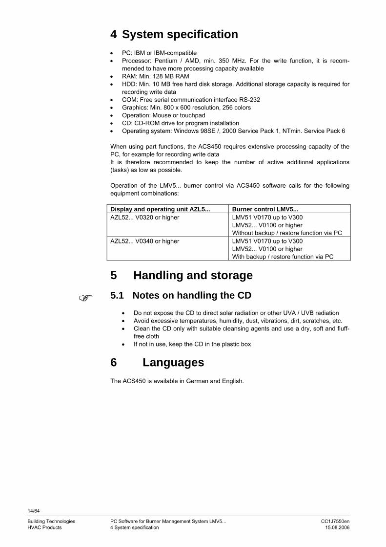
recording write data • COM: Free serial communication interface RS-232 • Graphics: Min. 800 x 600 resolution, 256 colors • Operation: Mouse or touchpad • CD: CD-ROM drive for program installation • Operating system: Windows 98SE /, 2000 Service Pack 1, NTmin. Service Pack 6 When using part functions, the ACS450 requires extensive processing capacity of the PC, for example for recording write data It is therefore recommended to keep the number of active additional applications (tasks) as low as possible. Operation of the LMV5... burner control via ACS450 software calls for the following equipment combinations: Display and operating unit AZL5... Burner control LMV5... AZL52... V0320 or higher LMV51 V0170 up to V300
LMV52... V0100 or higher Without backup / restore function via PC
AZL52... V0340 or higher LMV51 V0170 up to V300 LMV52... V0100 or higher With backup / restore function via PC
5 Handling and storage
5.1 Notes on handling the CD
• Do not expose the CD to direct solar radiation or other UVA / UVB radiation • Avoid excessive temperatures, humidity, dust, vibrations, dirt, scratches, etc. • Clean the CD only with suitable cleansing agents and use a dry, soft and fluff-
free cloth • If not in use, keep the CD in the plastic box
6 Languages The ACS450 is available in German and English.
14/64
Building Technologies PC Software for Burner Management System LMV5... CC1J7550en HVAC Products 4 System specification 15.08.2006
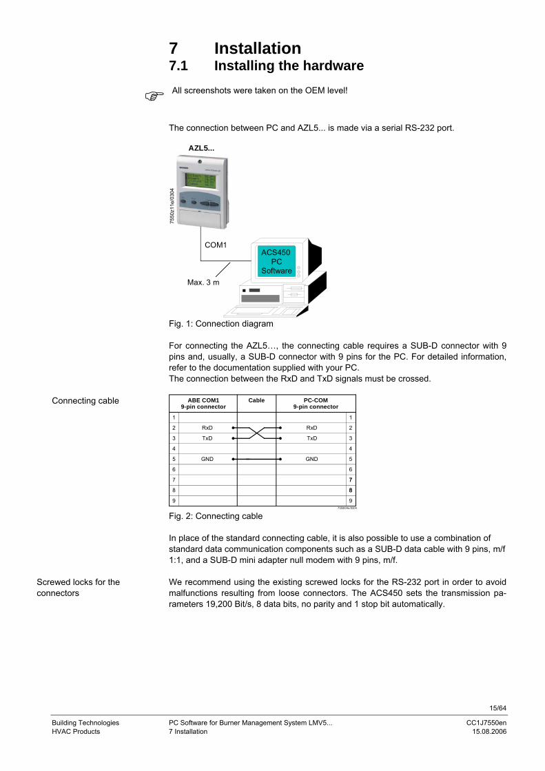
7 Installation 7.1 Installing the hardware All screenshots were taken on the OEM level!
The connection between PC and AZL5... is made via a serial RS-232 port.
AZL5...
COM1
Max. 3 m
7550
z11e
/030
4
ACS450PC
Software
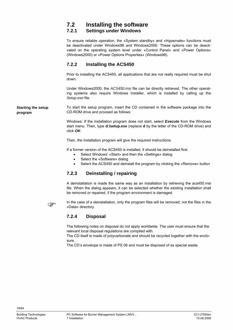
Fig. 1: Connection diagram For connecting the AZL5…, the connecting cable requires a SUB-D connector with 9 pins and, usually, a SUB-D connector with 9 pins for the PC. For detailed information, refer to the documentation supplied with your PC. The connection between the RxD and TxD signals must be crossed.
ABE COM19-pin connector
Cable
7550t04e/0304
PC-COM9-pin connector
RxD
1
2
3
4
5
6
7
8
9
TxD
GND
RxD
TxD
GND
1
2
3
4
5
6
77
88
9
Connecting cable
Fig. 2: Connecting cable In place of the standard connecting cable, it is also possible to use a combination of standard data communication components such as a SUB-D data cable with 9 pins, m/f 1:1, and a SUB-D mini adapter null modem with 9 pins, m/f. We recommend using the existing screwed locks for the RS-232 port in order to avoid malfunctions resulting from loose connectors. The ACS450 sets the transmission pa-rameters 19,200 Bit/s, 8 data bits, no parity and 1 stop bit automatically.
Screwed locks for the connectors
15/64
Building Technologies PC Software for Burner Management System LMV5... CC1J7550en HVAC Products 7 Installation 15.08.2006
7.2 Installing the software 7.2.1 Settings under Windows To ensure reliable operation, the «System standby» and «Hypernate» functions must be deactivated under Windows98 and Windows2000. These options can be deacti-vated on the operating system level under «Control Panel» and «Power Options» (Windows2000) or «Power Options Properties» (Windows98). 7.2.2 Installing the ACS450 Prior to installing the ACS450, all applications that are not really required must be shut down. Under Windows2000, the ACS450.msi file can be directly retrieved. The other operat-ing systems also require Windows Installer, which is installed by calling up the Setup.exe file. To start the setup program, insert the CD contained in the software package into the CD-ROM drive and proceed as follows:
Starting the setup program
Windows: If the installation program does not start, select Execute from the Windows start menu. Then, type d:\setup.exe (replace d by the letter of the CD-ROM drive) and click OK. Then, the installation program will give the required instructions.
If a former version of the ACS450 is installed, it should be deinstalled first.
• Select Windows’ «Start» and then the «Settings» dialog • Select the «Software» dialog • Select the ACS450 and deinstall the program by clicking the «Remove» button
7.2.3 Deinstalling / repairing A deinstallation is made the same way as an installation by retrieving the acs450.msi file. When the dialog appears, it can be selected whether the existing installation shall be removed or repaired, if the program environment is damaged.
In the case of a deinstallation, only the program files will be removed, not the files in the «Data» directory. 7.2.4 Disposal The following notes on disposal do not apply worldwide. The user must ensure that the relevant local disposal regulations are complied with. The CD itself is made of polycarbonate and should be recycled together with the enclo-sure. The CD’s envelope is made of PS 06 and must be disposed of as special waste.
16/64
Building Technologies PC Software for Burner Management System LMV5... CC1J7550en HVAC Products 7 Installation 15.08.2006
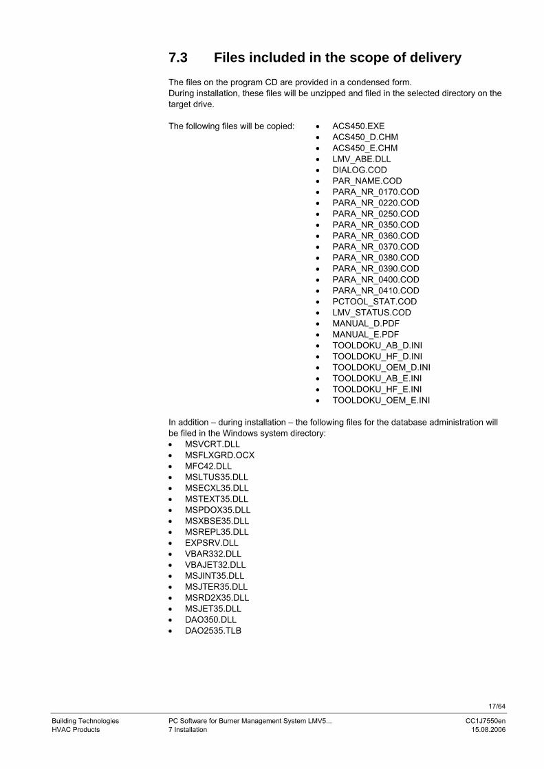
7.3 Files included in the scope of delivery The files on the program CD are provided in a condensed form. During installation, these files will be unzipped and filed in the selected directory on the target drive. The following files will be copied:
• ACS450.EXE • ACS450_D.CHM • • • • • • • • • • • • • • • • • • • • • • • •
• • MSFLXGRD.OCX • MFC42.DLL • • • • • MSXBSE35.DLL • • • • • • • • • •
ACS450_E.CHM LMV_ABE.DLL DIALOG.COD PAR_NAME.COD PARA_NR_0170.COD PARA_NR_0220.COD PARA_NR_0250.COD PARA_NR_0350.COD PARA_NR_0360.COD PARA_NR_0370.COD PARA_NR_0380.COD PARA_NR_0390.COD PARA_NR_0400.COD PARA_NR_0410.COD PCTOOL_STAT.COD LMV_STATUS.COD MANUAL_D.PDF MANUAL_E.PDF TOOLDOKU_AB_D.INI TOOLDOKU_HF_D.INI TOOLDOKU_OEM_D.INI TOOLDOKU_AB_E.INI TOOLDOKU_HF_E.INI TOOLDOKU_OEM_E.INI
In addition – during installation – the following files for the database administration will be filed in the Windows system directory:
MSVCRT.DLL
MSLTUS35.DLL MSECXL35.DLL MSTEXT35.DLL MSPDOX35.DLL
MSREPL35.DLL EXPSRV.DLL VBAR332.DLL VBAJET32.DLL MSJINT35.DLL MSJTER35.DLL MSRD2X35.DLL MSJET35.DLL DAO350.DLL DAO2535.TLB
17/64
Building Technologies PC Software for Burner Management System LMV5... CC1J7550en HVAC Products 7 Installation 15.08.2006

7.4 Generated files When making a connection to the LMV5… system, the ACS450 generates a data direc-tory on a level below the program directory. The following files will be saved in the directory: • • •
Database files for the parameter settings Database files for trending data Parameter files for parameter sets
18/64
Building Technologies PC Software for Burner Management System LMV5... CC1J7550en HVAC Products 7 Installation 15.08.2006
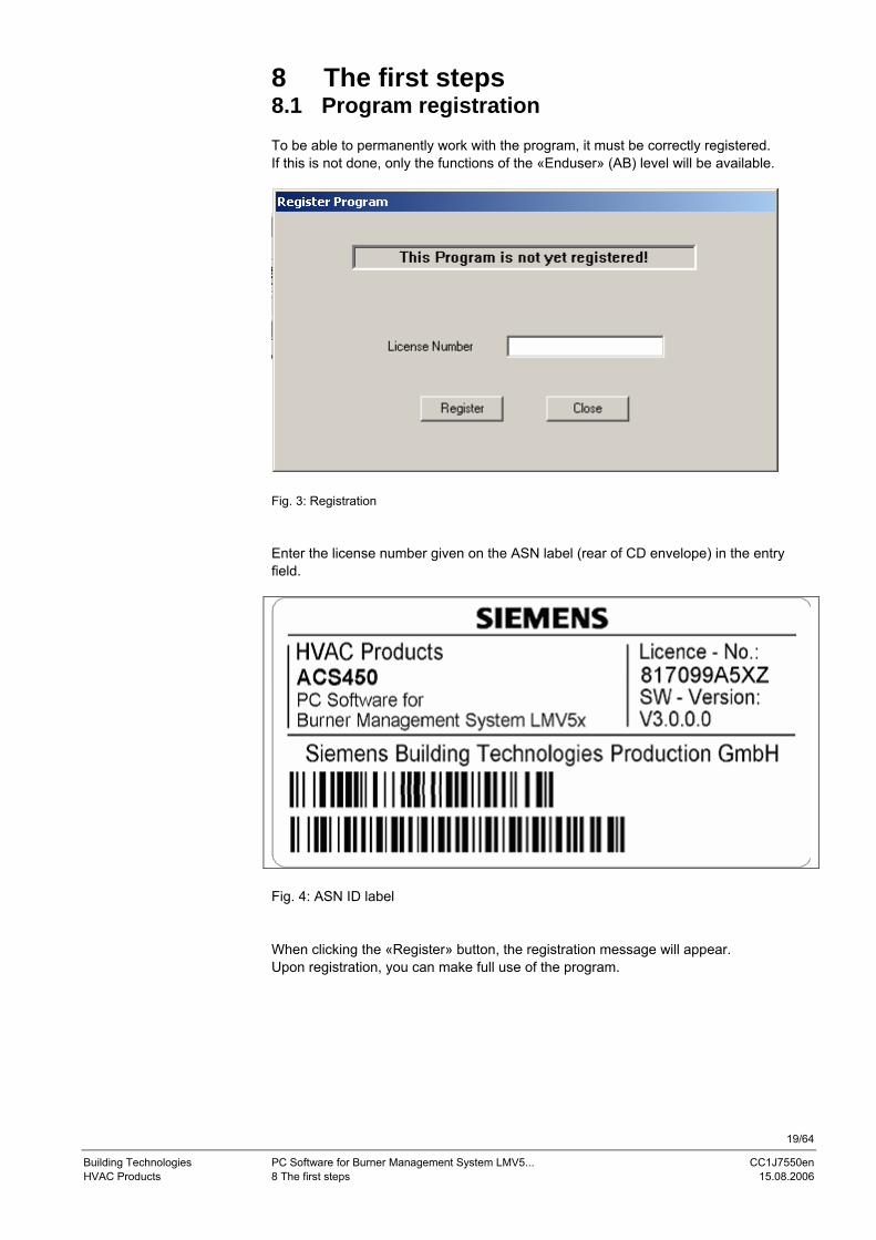
8 The first steps 8.1 Program registration To be able to permanently work with the program, it must be correctly registered. If this is not done, only the functions of the «Enduser» (AB) level will be available.
Fig. 3: Registration Enter the license number given on the ASN label (rear of CD envelope) in the entry field.
Fig. 4: ASN ID label When clicking the «Register» button, the registration message will appear. Upon registration, you can make full use of the program.
19/64
Building Technologies PC Software for Burner Management System LMV5... CC1J7550en HVAC Products 8 The first steps 15.08.2006

8.2 Operation of the ACS450 in connection with the LMV5… system Warning
Before connecting the ACS450 to an LMV5… system, the safety warnings given in chapter 2 must be strictly observed. Before connecting the ACS450 to an LMV5… system, it must be ensured that the pa-rameters set on the LMV5... have been protected by individual burner identification. This can be checked with the AZL5... on the «Operation» → «Burner Identification» menu. If required, burner identification can be entered via the OEM level. For that pur-pose, use the menu of the AZL5... «Update» → «Burner Identification».
Individual burner identification
The individual burner identification is automatically the file name of the database file which serves as a basis for the existing menu and parameter structure.
Only individual burner identification ensures unambiguous assignment of the parameter backup on the AZL5... to the associated LMV5... system components. This makes cer-tain that inadmissible or unintentional parameter set transmissions between different boiler plants will be prevented. When burner identification is ensured, proceed as follows: • Connect the PC to the COM 1 port of the AZL5... via the serial connection • Set the AZL5... for use with the ACS450 via «Operation» → «Optg Mode Select»
→ «Interface PC» • Start the ACS450 program by double clicking on the link symbol on the desktop • Read the «Safety Warnings» dialog carefully and confirm by clicking «Ok» • After starting the ACS450 program, there is no connection yet to the LMV5… sys-
tem via the AZL5... In this mode, previous recordings can be viewed via the file dia-log
• Establish the connection via the ACS450 by using the menu bar of the ACS450. Select «System LMV5x» → «Connect»
Fig. 5: Connection
20/64
Building Technologies PC Software for Burner Management System LMV5... CC1J7550en HVAC Products 8 The first steps 15.08.2006

• Select the access level and enter the password in the «Password» dialog box.
Then, confirm by clicking «Ok» Note: The «Enduser» level requires no password.
Fig. 6: Password
• When, after entering the password, a connection has been established, the pro-
gram reads the system’s burner identification. Then, a search is made to find out if there is a database with the name of that burner identification. If that is not the case, the menu and parameter structure of the AZL5... will be read in and filed in the database. Then, the «Parameters» menu will automatically be generated on the «System LMV5x» menu of the menu bar
• Select the required function via the «Parameters» menu. Here, the menu structure corresponds to that of the connected AZL5...
8.3 Closing the program The online mode can be closed via «System LMV5x» → «Disconnect». The «Close» dialog will appear. It offers you the choice of reading in parameters for off-line mode. To close the ACS450, select the «File Close» menu.
If «Disconnect» is not executed before «Close», the ACS450 will automatically close the connection.
8.4 ACS450 in offline mode Here, data that were previously uploaded online can be displayed or printed out with no need for having a connection to the plant. For that purpose, open the database file in which the parameters were saved via the «File» menu and select «Show Parameters». If successful, the read functions are available as if a connection to the plant existed. For more details, refer to chapter 10.
21/64
Building Technologies PC Software for Burner Management System LMV5... CC1J7550en HVAC Products 8 The first steps 15.08.2006

9 General operating functions 9.1 Scope of functions Basically, the scope of functions of the ACS450 corresponds to those of the AZL5... of the LMV5... system. The major extended operating and display choices provided by a PC-supported tool are the following: • • • •
• • • • • • • •
Graphic support when setting the electronic fuel / air ratio control system Trend recording (write function) Print functions for documenting the plant settings Backup / Restore via PC
The following functions are not provided by the PC tool and must be performed directly on the AZL5...:
TÜV test Starting adaption Resetting the basic unit Selecting the operating mode of the AZL5... Setting the display contrast of the AZL5... Addressing the actuators Deleting the curves (fuel / air ratio control system) Updating the passwords
9.2 Title bar After opening a connection, or in offline mode, the title bar shows the name of the opened database next to the program name. That name corresponds to the burner identification of the LMV5... system.
22/64
Building Technologies PC Software for Burner Management System LMV5... CC1J7550en HVAC Products 9 General operating functions 15.08.2006

9.3 Operating mode 9.3.1 Operation of the ACS450 on the plant 9.3.1.1 Overview Connect the PC to the serial COM 1 port of the AZL5... using a connecting cable. When the connection is opened, the ACS450 checks whether this is the first time op-eration is started or whether it is a repeated process. For that purpose, it is checked whether a valid file with the required system information already exists in the data directory of the ACS450. 9.3.1.2 First-time operation When opening a connection to the plant for the first time, the program reads information for generating the menu and parameter definitions and stores these data in a database. The file name of the database is identical to the selected burner identification, and the name extension is «mdb». The file is made up in Microsoft Access format. The file will be filed in the data directory. A process bar shows the current process. 9.3.1.3 Repeated operation When connecting the ACS450 to the plant and the program is started, the burner identi-fication of the LMV5... system is compared with the file name in the data directory to see if a file already exists. If that is the case and the parameter settings of the file correspond to those in the LMV5… system, time-consuming reading in is no longer required and – after an integ-rity check with the help of a CRC comparison – the PC will adopt that database.
23/64
Building Technologies PC Software for Burner Management System LMV5... CC1J7550en HVAC Products 9 General operating functions 15.08.2006

9.4 Password 9.4.1 Overview The passwords are assigned to the «Service» (HF) and «OEM» access levels, which mean that the parameters that can be changed are only those associated with the re-spective access level.
AB Enduser HF Service OEM Burner manufacturer
The «Enduser» (AB) level does not have a password protection since no safety-related parameter settings can be made on that level.
The ACS450 does not save its own passwords. This means that the password to be entered for the associated level corresponds to that of the LMV5... system. 9.4.2 Entering the password When entering the password, a distinction must be made between uppercase and low-ercase letters. After entering, confirm by clicking «Ok» or deactivate the password entry by clicking «Close». If no password is entered, the «Enduser» (AB) level is active. The password time set is 30 minutes. The password expires if there are no user activities via the keyboard or the mouse for 30 minutes. When the password time has expired, the following dialog will appear. The user can re-enter the password.
Fig. 7: Valid time has elapsed
24/64
Building Technologies PC Software for Burner Management System LMV5... CC1J7550en HVAC Products 9 General operating functions 15.08.2006

9.4.3 Changing and leaving the password level The password can be changed via «Parameters» → «Password Login». Using the next menu item «Password Logout», it is possible to return to the «Enduser» (AB) level.
Fig. 8: Changing the password
25/64
Building Technologies PC Software for Burner Management System LMV5... CC1J7550en HVAC Products 9 General operating functions 15.08.2006

9.5 Normal operation In this dialog box, general information about the operating state of the LMV5... system is given. The user cannot make any entries.
Fig. 9: Normal operation The data are updated at 3-second intervals. To check an active connection between ACS450 and AZL5..., there is an indicator light «PC ↔ AZL» in the upper right hand corner. It flashes when data are transmitted.
Updating
The fuel-dependent ranges are active or inactive, depending on the selected type of fuel. Activated inputs and outputs appear in green.
Display and symbols
26/64
Building Technologies PC Software for Burner Management System LMV5... CC1J7550en HVAC Products 9 General operating functions 15.08.2006
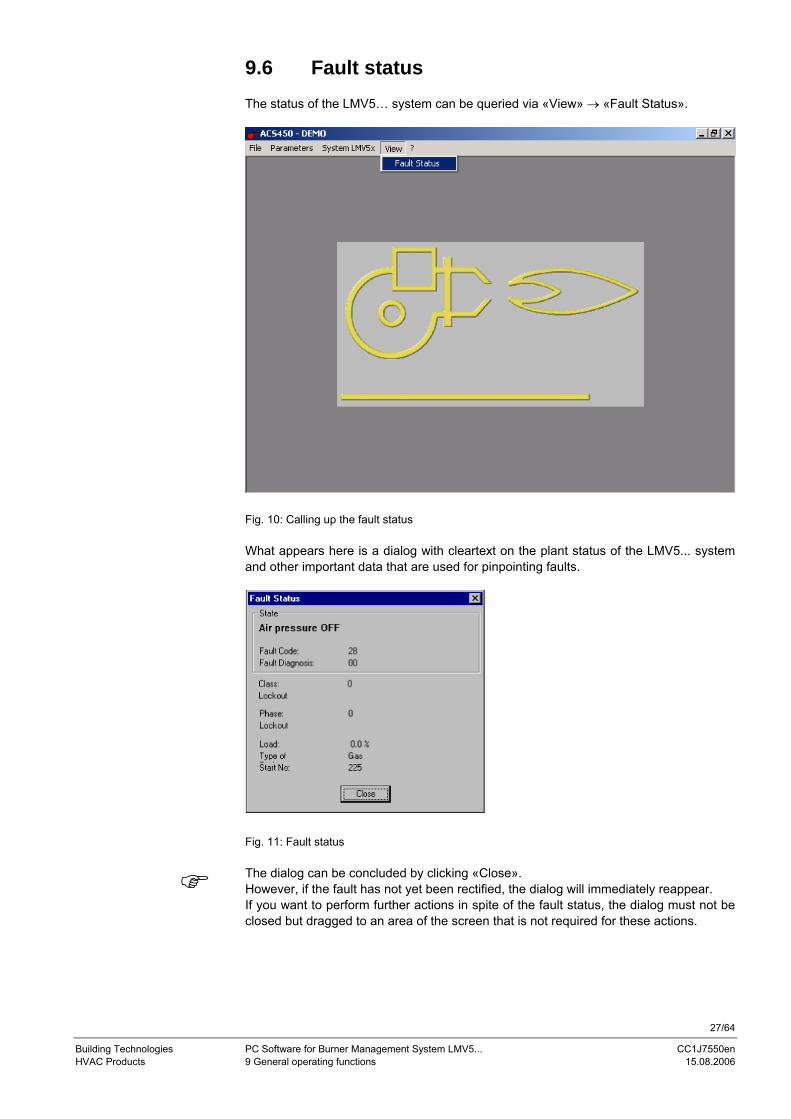
9.6 Fault status The status of the LMV5… system can be queried via «View» → «Fault Status».
Fig. 10: Calling up the fault status What appears here is a dialog with cleartext on the plant status of the LMV5... system and other important data that are used for pinpointing faults.
Fig. 11: Fault status
The dialog can be concluded by clicking «Close». However, if the fault has not yet been rectified, the dialog will immediately reappear. If you want to perform further actions in spite of the fault status, the dialog must not be closed but dragged to an area of the screen that is not required for these actions.
27/64
Building Technologies PC Software for Burner Management System LMV5... CC1J7550en HVAC Products 9 General operating functions 15.08.2006

9.7 Parameter settings and configuration Warning Observe the safety warnings given in chapter 2!
9.7.1 Introduction With the ACS450, parameters can be changed the way they are with the AZL5.... When selecting a parameter dialog, it is always the current value of the AZL5... that is read in. Parameters must always be changed with the «Slider» or the «+» and «-» buttons. In the case of a parameter with predefined text, it is also possible to select a value via the list box. The program reads the permissible minimum and maximum limit values as well as the increments from the AZL5... Settings can only be made within the permissible limit values using the available incre-ments. This procedure is aimed at preventing false operations. To document the parameter set, it is also possible to store all parameters in a data-base. 9.7.2 Procedure Between PC and AZL5..., the procedure is the following: • Change one or several parameters in the «Input» column • For that purpose, select a field in the «Input» column • In accordance with Windows standards, the field appears with a blue background
and the value appears in white
Fig. 12: Selecting a parameter
28/64
Building Technologies PC Software for Burner Management System LMV5... CC1J7550en HVAC Products 9 General operating functions 15.08.2006
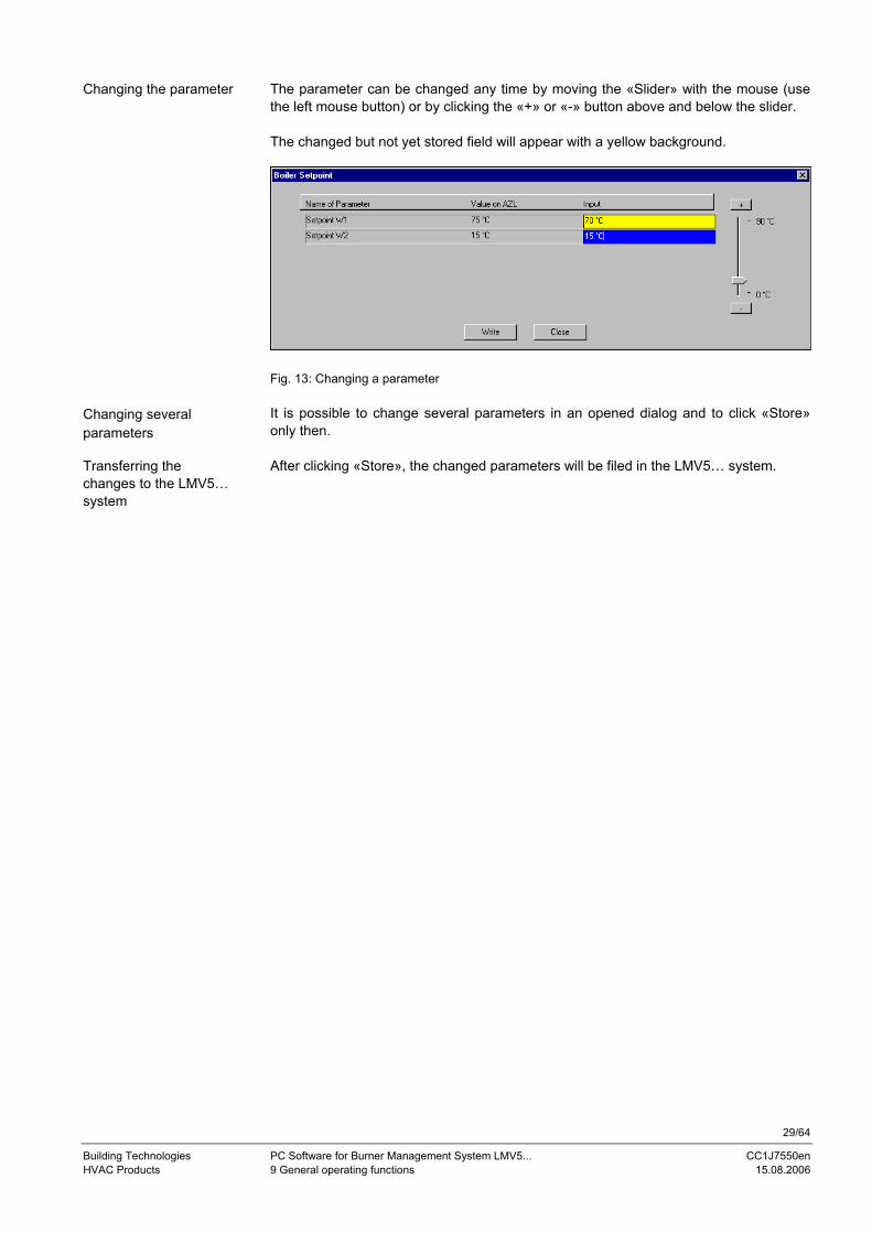
The parameter can be changed any time by moving the «Slider» with the mouse (use the left mouse button) or by clicking the «+» or «-» button above and below the slider.
Changing the parameter
The changed but not yet stored field will appear with a yellow background.
Fig. 13: Changing a parameter It is possible to change several parameters in an opened dialog and to click «Store» only then.
Changing several parameters
After clicking «Store», the changed parameters will be filed in the LMV5… system. Transferring the
changes to the LMV5… system
29/64
Building Technologies PC Software for Burner Management System LMV5... CC1J7550en HVAC Products 9 General operating functions 15.08.2006

After delivering the parameters, the PC software will automatically read back the data from the AZL5... If successful, the ACS450 ensures that the entry field will appear with a green background. Then, a dialog will prompt you to check all displayed values again. This is made by a visual comparison of the «Value on AZL» with the «Input». The rele-vant values will be shown with a green background, indicating the values to be verified.
Checking storing
This visual check is mandatory!
Fig. 14: Verifying the parameter change If the transmission has not been successful, the «Input» field will appear with a red background and the value on the AZL5... also.
Fault during the storing procedure
The ACS450 checks if a fault occurred during storage or during the subsequent reading back of the value and if, after successful storage and reading back, both values are identical. If a fault occurs, a dialog also tells you about it.
Observe the notes given in chapter 12! Example: The LMV5... system is in the operating position. It is not permitted to set the parameters of «Fan Runup Time». The system cannot make these parameter settings.
Fig. 15: Fault during the parameter setting procedure
30/64
Building Technologies PC Software for Burner Management System LMV5... CC1J7550en HVAC Products 9 General operating functions 15.08.2006

When making a change to the «Input» column and clicking «Close», the following dia-log appears:
Aborting the parameter change
Fig. 16: Message appearing during the parameter setting procedure When selecting «Yes», you will go back to the last setting dialog and the changed fields in the «Input» range are still active. When selecting «No», the settings of the last dialog will be discarded.
31/64
Building Technologies PC Software for Burner Management System LMV5... CC1J7550en HVAC Products 9 General operating functions 15.08.2006
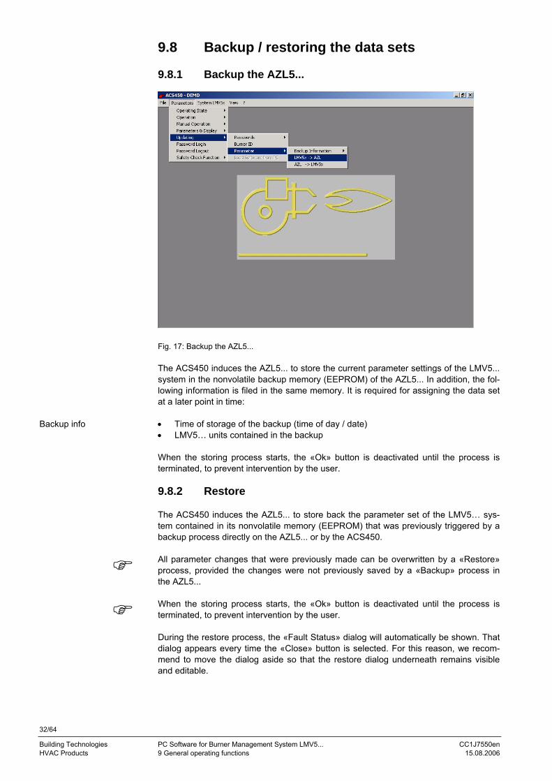
9.8 Backup / restoring the data sets 9.8.1 Backup the AZL5...
Fig. 17: Backup the AZL5... The ACS450 induces the AZL5... to store the current parameter settings of the LMV5... system in the nonvolatile backup memory (EEPROM) of the AZL5... In addition, the fol-lowing information is filed in the same memory. It is required for assigning the data set at a later point in time: • Time of storage of the backup (time of day / date) Backup info • LMV5… units contained in the backup When the storing process starts, the «Ok» button is deactivated until the process is terminated, to prevent intervention by the user. 9.8.2 Restore The ACS450 induces the AZL5... to store back the parameter set of the LMV5… sys-tem contained in its nonvolatile memory (EEPROM) that was previously triggered by a backup process directly on the AZL5... or by the ACS450.
All parameter changes that were previously made can be overwritten by a «Restore» process, provided the changes were not previously saved by a «Backup» process in the AZL5...
When the storing process starts, the «Ok» button is deactivated until the process is terminated, to prevent intervention by the user. During the restore process, the «Fault Status» dialog will automatically be shown. That dialog appears every time the «Close» button is selected. For this reason, we recom-mend to move the dialog aside so that the restore dialog underneath remains visible and editable.
32/64
Building Technologies PC Software for Burner Management System LMV5... CC1J7550en HVAC Products 9 General operating functions 15.08.2006
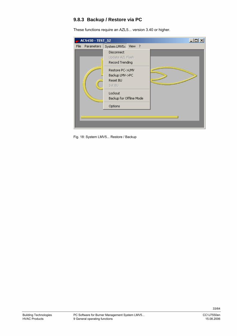
9.8.3 Backup / Restore via PC These functions require an AZL5... version 3.40 or higher.
Fig. 18: System LMV5... Restore / Backup
33/64
Building Technologies PC Software for Burner Management System LMV5... CC1J7550en HVAC Products 9 General operating functions 15.08.2006

9.8.3.1 Backup
Fig. 19: Backup LMV5... ↔ PC Backup can be retrieved via «System LMV5x» → «Backup LMV → PC». When calling up the function, the AZL5... will automatically be requested to update its parameter set. When this is being done, the status field displays «Input File Name» and the «Save in file» button becomes active. Individual information about the parameter set can be en-tered in the text field for comments. This information is then saved in the file together with the parameters to be displayed again later for restoring. After selecting this button, the file dialog will appear. When the file name is confirmed, the saving process is started. The result will appear in the status field.
34/64
Building Technologies PC Software for Burner Management System LMV5... CC1J7550en HVAC Products 9 General operating functions 15.08.2006
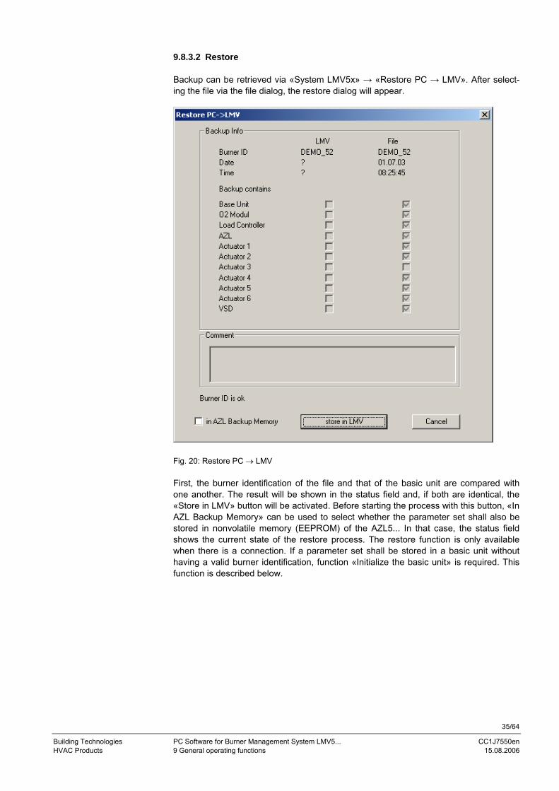
9.8.3.2 Restore Backup can be retrieved via «System LMV5x» → «Restore PC → LMV». After select-ing the file via the file dialog, the restore dialog will appear.
Fig. 20: Restore PC → LMV First, the burner identification of the file and that of the basic unit are compared with one another. The result will be shown in the status field and, if both are identical, the «Store in LMV» button will be activated. Before starting the process with this button, «In AZL Backup Memory» can be used to select whether the parameter set shall also be stored in nonvolatile memory (EEPROM) of the AZL5... In that case, the status field shows the current state of the restore process. The restore function is only available when there is a connection. If a parameter set shall be stored in a basic unit without having a valid burner identification, function «Initialize the basic unit» is required. This function is described below.
35/64
Building Technologies PC Software for Burner Management System LMV5... CC1J7550en HVAC Products 9 General operating functions 15.08.2006
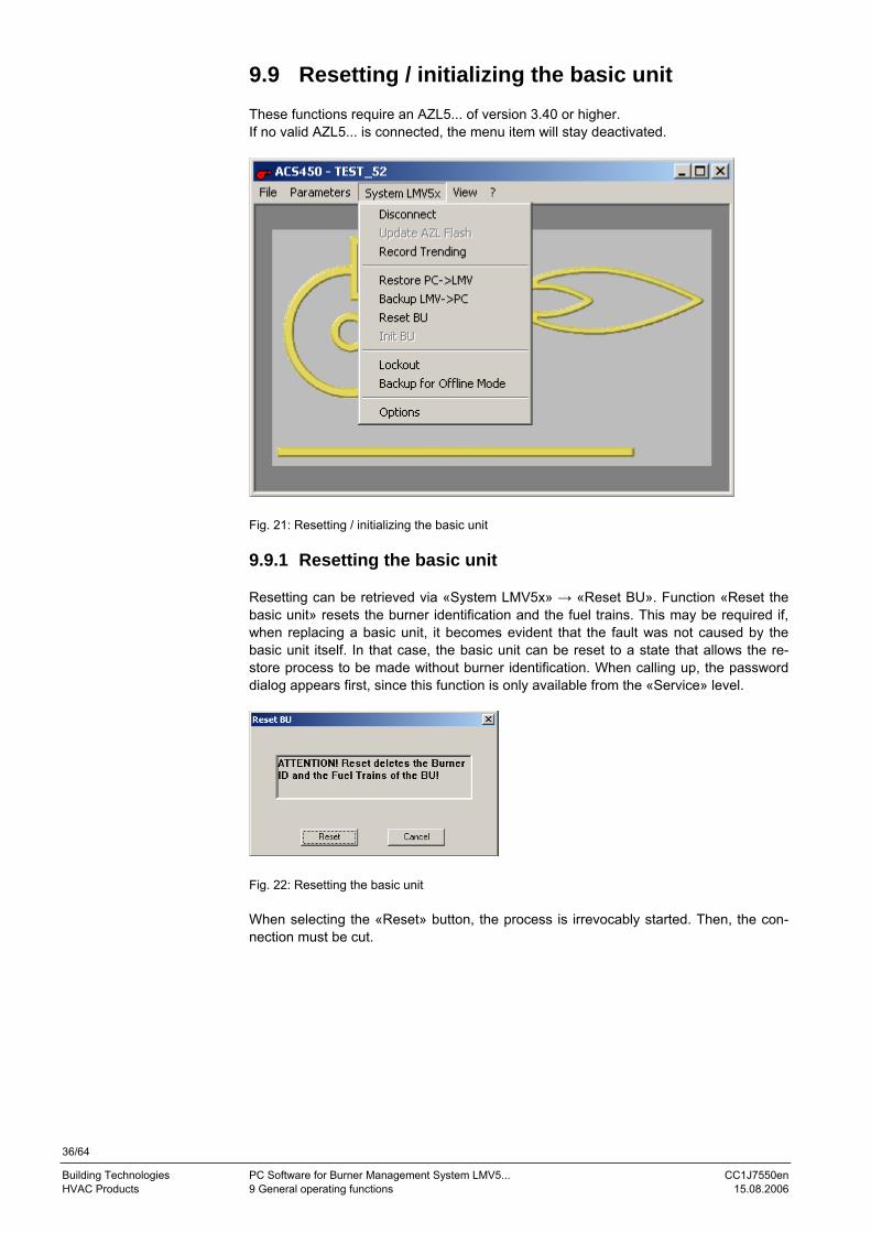
9.9 Resetting / initializing the basic unit These functions require an AZL5... of version 3.40 or higher. If no valid AZL5... is connected, the menu item will stay deactivated.
Fig. 21: Resetting / initializing the basic unit 9.9.1 Resetting the basic unit Resetting can be retrieved via «System LMV5x» → «Reset BU». Function «Reset the basic unit» resets the burner identification and the fuel trains. This may be required if, when replacing a basic unit, it becomes evident that the fault was not caused by the basic unit itself. In that case, the basic unit can be reset to a state that allows the re-store process to be made without burner identification. When calling up, the password dialog appears first, since this function is only available from the «Service» level.
Fig. 22: Resetting the basic unit When selecting the «Reset» button, the process is irrevocably started. Then, the con-nection must be cut.
36/64
Building Technologies PC Software for Burner Management System LMV5... CC1J7550en HVAC Products 9 General operating functions 15.08.2006

9.9.2 Initializing the basic unit Resetting can be retrieved via «System LMV5x» → «Initialize BU». In principle, function «Initialize BU» performs the same process as «Restore PC → LMV», the difference be-ing that a valid burner identification is required here. Hence, operation is analogous to the above function.
9.10 Switch-off function (manual locking of the basic unit LMV5...) Warning Observe note given in chapter 12! Manual locking can be retrieved via menu «System LMV5x» → «Lockout». This function can be performed only if the connection to the LMV5... system is acti-vated. If lockout is successful, the LMV5… system will deliver fault status «Manual Lockout AZL» to the ACS450. In that case, the following dialog will appear:
Fig. 23: Manual lockout
Due to the intrinsic delay of the system, the time required from manual lockout to lock-out of the basic unit LMV5... is about 2 seconds, and another 10 seconds maximum for the dialog to appear. A reset with the ACS450 cannot be made. Lockout on the AZL5... is also possible in interface mode by simultaneously pressing the Enter and Esc buttons.
37/64
Building Technologies PC Software for Burner Management System LMV5... CC1J7550en HVAC Products 9 General operating functions 15.08.2006

9.11 Adjusting the fuel / air ratio control system Warning Observe the note given in chapter 12! 9.11.1 Modulating operation 9.11.1.1 Overview This menu item contains the subitems «Curve Display» and «Curve Setup» for firing on gas or oil. Enter the curvepoints graphically with the mouse or with the arrow keys. The arrow keys are used in particular for making the fine adjustments. The display of the curve is updated while the settings are made. For each type of fuel, a maximum of 6 curves each with 15 curvepoints is provided. The curvepoints and the other data required (e.g. special positions) are read by the AZL5... when selecting the function. When curve-points become available, they will be graphically displayed and connected by straight lines.
Entering the curvepoints
In addition, when starting the adjustment of the fuel / air ratio control system, the follow-ing system data will be displayed:
• Current operating phase • Current load • Current O2 value • Fault status
The operating element and the curvepoints for the actuators and the variable speed drive appear only when activated.
Fig. 24: Curve dialog
38/64
Building Technologies PC Software for Burner Management System LMV5... CC1J7550en HVAC Products 9 General operating functions 15.08.2006

The «Load» box shows the current load as all actuators are driven to their respective positions. In addition, when selecting an existing curvepoint, the load assigned to the positions is displayed here. The assignment of load can also be changed via this box (refer to «Changing the load assignment of a curvepoint»). Entry box «Manual Load» serves for predefining the required load the system shall approach. When selecting the «Curve Dialog» menu, all curvepoints available at that time will be shown as a curve. If no curvepoints exist at the time the menu is opened, the graph will be shown without any curves. In the case of subsequent startup and an activated curve dialog, the first point of the curve storage of the LMV5... basic unit will automatically be displayed when the operating phase is reached.
This point is automatically generated by the basic unit and corresponds to the ignition positions. The parameter setting mode of the LMV5... basic unit for setting curve parameters be-comes active only when the first parameter settings in the curve dialog are made: - Adjust the manual load (by moving the slider, entry via the keyboard or the spinner
associated with the text field) and then click «Go to» or «Confirm» - Delete a curvepoint
Fig. 25: Setting elements for the manual load
39/64
Building Technologies PC Software for Burner Management System LMV5... CC1J7550en HVAC Products 9 General operating functions 15.08.2006

Fig. 26: Setting elements for the manual load (without „Go to“)
The settings can be made in the following phases: • Lockout (phase number 0) • Standby (phase number 12) • Operation (phase number 60)
40/64
Building Technologies PC Software for Burner Management System LMV5... CC1J7550en HVAC Products 9 General operating functions 15.08.2006

9.11.1.2 Defining a new curvepoint position For that purpose, the predefined load is required at which a new curvepoint shall be es-tablished. Set the slider for the manual load (pink triangle) to the new load. This is made in one of the following ways: • Select the slider with the mouse and shift it while keeping the left mouse button de-
pressed Changing the actuator positions at a curvepoint • Click the arrow buttons next to «Manual Load»
• Press the arrow keys of the PC keyboard after selecting the slider with the mouse or after selecting the manual load
Then, click «Go to». When the predefined load is reached, the «Set Point» button will become active and can be clicked. This is possible between curvepoints that already exist, and below and above the curves that have already been parameterized. In that case, extrapolated straight lines are used that represent extensions of the last curvepoints. From now on, until «Store» or «Discard» is clicked, no action can be performed, apart from changing the actuator positions at this curvepoint, e.g. the «Cancel Point» action is not possible. Next, select the actuator whose current position shall be changed. This is made via the selection in the options field.
Fig. 27: Selection of actuator
41/64
Building Technologies PC Software for Burner Management System LMV5... CC1J7550en HVAC Products 9 General operating functions 15.08.2006

To change the actuator position, set the mouse pointer to the current position and shift the marking while keeping the left mouse button depressed. Release the button and the curve will be redrawn. To newly change a position that has already been shifted, set the mouse pointer to the square symbol and then change as described above. A fine adjustment can be made with the arrow buttons of the respective actuator in the dialog window.
Fine adjustment
After changing the position, click «Go to». This causes the actuators to travel to the preselected positions. Like the actuator positions, the load assignment of a curvepoint can be changed. This has an impact on the slope of the curves. The load assignment can be changed by shifting the currently handled curvepoint (blue background) or by clicking the associ-ated arrow buttons (top right). The load assignment can only be changed within two neighboring curvepoints.
Changing the load assignment of a curvepoint
To store the curvepoint in the LMV5... system as a new curvepoint with its associated curvepoint, click the «Store» button.
Storing / discarding the new point
When selecting «Discard», the curvepoint in the ACS450 can be deleted. In that case, there is no storage in the LMV5... system and the actuators will automatically return to the positions they had assumed before the positions were changed. 9.11.1.3 Changing an existing curvepoint To change an existing curvepoint, proceed as follows: - Set the mouse cursor to the markers of an existing curvepoint (grey triangles) - Confirm by clicking «Go to» When reaching the load corresponding to the curvepoint, all following actions can be performed as described in subsection 9.11.1.2. When clicking «Discard», the curvepoint with its values is retained in the LMV5... sys-tem. 9.11.1.4 Changing an existing curvepoint „without Go to“ To change an existing curvepoint, proceed as follows: - Set the mouse cursor to the markers of an existing curvepoint (grey triangles). - Set the marker to «cold» - Confirm by clicking «Confirm» When reaching the load corresponding to the curvepoint, all following actions can be performed as described in subsection 9.11.1.2. It is to be noted here, however, that «Go to» will be replaced by «Confirm» and, for the curvepoint to be changed, the system need not (!) operate at the output of that curve-point.
42/64
Building Technologies PC Software for Burner Management System LMV5... CC1J7550en HVAC Products 9 General operating functions 15.08.2006
9.11.1.5 Deleting a curvepoint To delete a curvepoint, proceed as follows:
- Click «Delete » - Click on the curvepoint to be deleted (grey rider). The point will then be deleted - The dialog can now be closed or the curvepoints changed, new ones added, or ex-
isting curvepoints deleted - To delete another point, click «Delete» again first 9.11.1.6 Quitting the curve dialog To terminate the setting of the curve, click «Close».
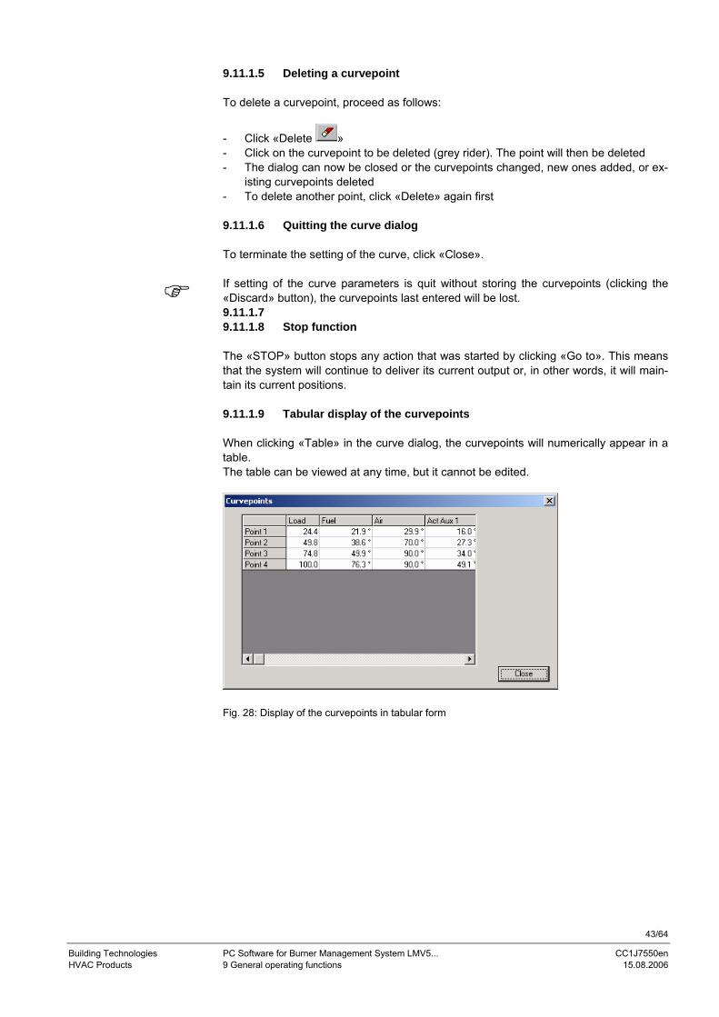
If setting of the curve parameters is quit without storing the curvepoints (clicking the «Discard» button), the curvepoints last entered will be lost. 9.11.1.7 9.11.1.8 Stop function The «STOP» button stops any action that was started by clicking «Go to». This means that the system will continue to deliver its current output or, in other words, it will main-tain its current positions. 9.11.1.9 Tabular display of the curvepoints When clicking «Table» in the curve dialog, the curvepoints will numerically appear in a table. The table can be viewed at any time, but it cannot be edited.
Fig. 28: Display of the curvepoints in tabular form
43/64
Building Technologies PC Software for Burner Management System LMV5... CC1J7550en HVAC Products 9 General operating functions 15.08.2006

9.11.1.10 Printing When clicking «Print», the print dialog of Windows appears. After selecting the required printer, the setting of the system will graphically appear. To permit unambiguous identification, the printout will contain the following data: • • •
Burner identification Type of fuel Date / time of printout
44/64
Building Technologies PC Software for Burner Management System LMV5... CC1J7550en HVAC Products 9 General operating functions 15.08.2006
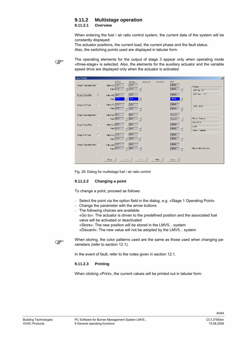
9.11.2 Multistage operation 9.11.2.1 Overview When entering the fuel / air ratio control system, the current data of the system will be constantly displayed: The actuator positions, the current load, the current phase and the fault status. Also, the switching points used are displayed in tabular form.
The operating elements for the output of stage 3 appear only when operating mode «three-stage» is selected. Also, the elements for the auxiliary actuator and the variable speed drive are displayed only when the actuator is activated.
Fig. 29: Dialog for multistage fuel / air ratio control 9.11.2.2 Changing a point To change a point, proceed as follows: − Select the point via the option field in the dialog, e.g. «Stage 1 Operating Point» − Change the parameter with the arrow buttons − The following choices are available:
«Go to»: The actuator is driven to the predefined position and the associated fuel valve will be activated or deactivated «Store»: The new position will be stored in the LMV5... system «Discard»: The new value will not be adopted by the LMV5... system
When storing, the color patterns used are the same as those used when changing pa-rameters (refer to section 12.1). In the event of fault, refer to the notes given in section 12.1. 9.11.2.3 Printing When clicking «Print», the current values will be printed out in tabular form.
45/64
Building Technologies PC Software for Burner Management System LMV5... CC1J7550en HVAC Products 9 General operating functions 15.08.2006

9.12 O2 setting Warning Observe the note given in chapter 12! When setting the O2 values, the min values must be parameterized first whereupon the fuel / air ratio values can be set. When calling up the setup, a check is first made to see if min. 3 curvepoints are avail-able. As with the fuel / air ratio setting, available curvepoints are represented by graphic symbols (little triangles). 9.12.1 Setting the O2 min values
Fig. 30: Making the O2 setting 9.12.1.1 Direct entry of values With the direct entry, a curvepoint is first selected by clicking on the symbol. Then, the «O2 Min Value» option must be activated. Use the arrow buttons to set the O2 value. The value will be stored by selecting the «Storing O2 Min Value» button. 9.12.1.2 Setting by reducing the air rate To do this, proceed as follows:
• Select the curvepoint by clicking on the symbol • Select the «P Air manual» option • Confirm by selecting the «Go to» button
After reaching the curvepoint, use the arrow buttons and then select «Go to» to reduce the amount of combustion air. The «act. O2 Value» field shows the current O2 value. When the required min value is reached, select the «Storing O2 Min Value» button to store the current value.
46/64
Building Technologies PC Software for Burner Management System LMV5... CC1J7550en HVAC Products 9 General operating functions 15.08.2006
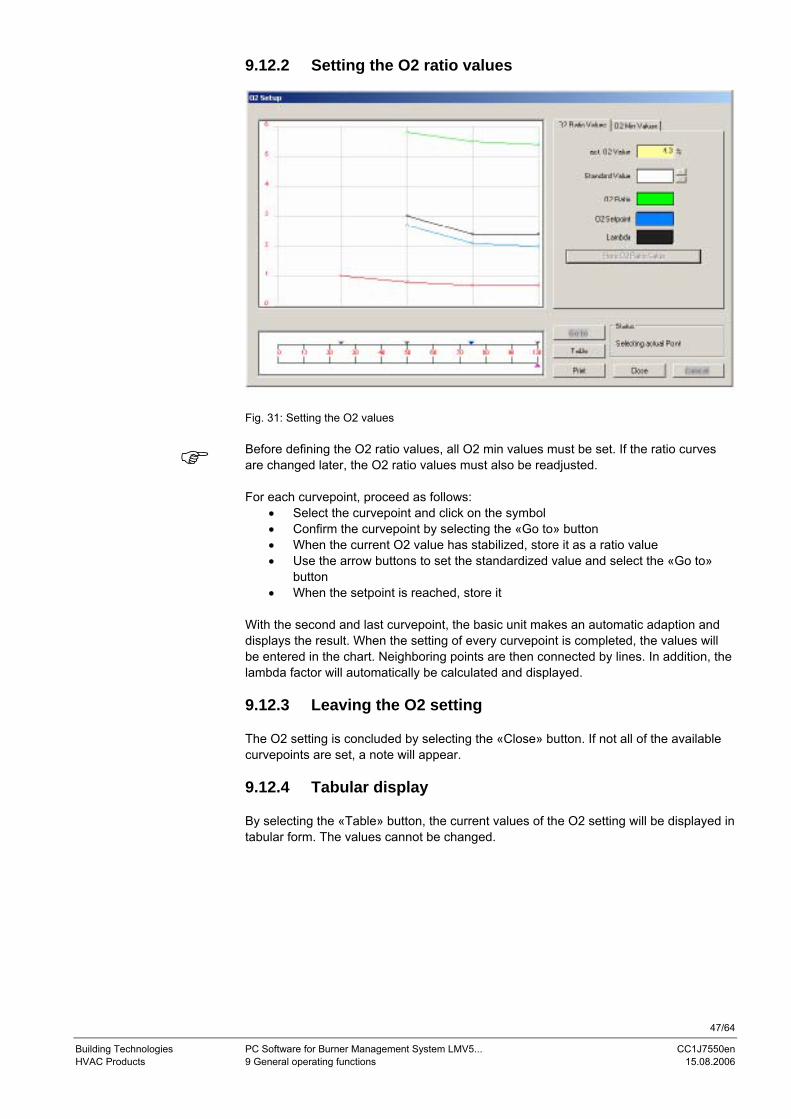
9.12.2 Setting the O2 ratio values
Fig. 31: Setting the O2 values
Before defining the O2 ratio values, all O2 min values must be set. If the ratio curves are changed later, the O2 ratio values must also be readjusted. For each curvepoint, proceed as follows:
• Select the curvepoint and click on the symbol • Confirm the curvepoint by selecting the «Go to» button • When the current O2 value has stabilized, store it as a ratio value • Use the arrow buttons to set the standardized value and select the «Go to»
button • When the setpoint is reached, store it
With the second and last curvepoint, the basic unit makes an automatic adaption and displays the result. When the setting of every curvepoint is completed, the values will be entered in the chart. Neighboring points are then connected by lines. In addition, the lambda factor will automatically be calculated and displayed. 9.12.3 Leaving the O2 setting The O2 setting is concluded by selecting the «Close» button. If not all of the available curvepoints are set, a note will appear. 9.12.4 Tabular display By selecting the «Table» button, the current values of the O2 setting will be displayed in tabular form. The values cannot be changed.
47/64
Building Technologies PC Software for Burner Management System LMV5... CC1J7550en HVAC Products 9 General operating functions 15.08.2006
9.12.5 Printing When selecting the «Print» button, the Windows standard printer dialog appears. After selection of the required printer, the setting of the O2 values will be given in graphic for-mat. In addition, for identification purposes, the following data are printed out:
• Burner identification • Type of fuel • Date and time of day of output
9.13 Fault history and lockout history 9.13.1 Fault history The fault history can be called up via «Parameters» → «Operating State» → «Fault History». The fault history is delivered in the form of a table. The structure of the fault history corresponds to that of the AZL5... With every fault en-try, the following information is delivered: • •
•
• •
•
Fault code, diagnostic code, fault class Phase of the LMV5... system, active type of fuel, load and start counter reading at the time the fault occurred Clear-text on the cause of fault
All entries stored in the AZL5... (up to 21) can be viewed in the dialog. When selecting the «Print» button, the current values will be printed out in tabular form. 9.13.2 Lockout history The lockout history can be called up via «Parameters» → «Operating State» → «Lock-out History». The lockout history is delivered in the form of a table. The structure of the lockout history corresponds to that of the AZL5... With every lock-out code, the following information is delivered:
Fault code, diagnostic code, fault class Phase of the LMV5... system, date and time of day, active type of fuel, load, start counter reading and number of operating hours at the time lockout occurred Clear-text on the cause of lockout
All entries stored in the AZL5... (up to 9) can be viewed in the dialog. When selecting the «Print» button, the current values will be printed out in tabular form.
9.14 Time of day and date A dialog that permits viewing of date, time of day and weekday of the real time clock of the LMV5… system can be called up via «Operation» → «Date / Time of Day» → «Set Clock». This dialog contains a button «Synchronizing the Clock», which performs the transfer of the system time from the PC to the LMV5... system.
48/64
Building Technologies PC Software for Burner Management System LMV5... CC1J7550en HVAC Products 9 General operating functions 15.08.2006

9.15 Trending / write function 9.15.1 Overview Here, an X-Y recorder is simulated that displays key system data. If required, these data can be stored in a database to be displayed later for diagnostic purposes, or for printing out. 9.15.2 Calling up the trending function When retrieving the trending function, a database needs to be specified first where the data shall be filed. It is possible to select an existing database by choosing the file name and by clicking «Open» for writing. In the database, the program reserves an en-try for the new measurement. The name will be assigned later in the main dialog. Alter-natively, a new database can be generated. The file name will be entered in the «File Name» field. The file name extension used is «tdb». Then, the entry is to be confirmed by clicking «Open». After selecting an existing or defining a new database, the trending window will appear.
49/64
Building Technologies PC Software for Burner Management System LMV5... CC1J7550en HVAC Products 9 General operating functions 15.08.2006

9.15.3 The trending window The trending window consists of a data window that is used for the graphic display of the values over time: X-axis: Time axis Y-axis: Indication of value; the associated unit depends on the channel settings;
the associated legend is to the right of the data window. The name of a channel appears when the mouse pointer is moved to the indicated value.
Fig. 32: The trending window When calling up the trending function , the current status of the selected channels will immediately appear, but there is no storage in the database yet. That takes place only after starting a recording, either by clicking «Start», or in the case of a trigger condition, if activated. Recording is terminated either by clicking «STOP» or in the case of a trig-ger condition. 9.15.4 Display of a channel A channel can be activated or deactivated with the associated check box. The color can be selected with a dialog, which appears in the legend after clicking the relevant button. To make the display clearer (making better use of the y-axis), a multiplier / divisor for the individual channels can be specified. This has an impact on the division ratio of the input variable and the displayed variable on the graph. Example: The temperature value of 500 °C will be displayed as 50 °C when making the following settings: • Multiplier = 1 • Divisor = 10
50/64
Building Technologies PC Software for Burner Management System LMV5... CC1J7550en HVAC Products 9 General operating functions 15.08.2006

9.15.5 «Display» settings In offline mode, the relevant buttons allow the display settings for the X- and Y-coordinates to be changed. For more detailed information, refer to subsection 10.5.3.1. 9.15.6 Printing In offline mode, the «Print» button allows the graph to be output on the printer based on the settings made before in «Display». For more detailed information, refer to subsection 10.5.3.1. 9.15.7 Setting the interval The interval for reading in the measurements can be set in increments between 1 and 20 seconds.
51/64
Building Technologies PC Software for Burner Management System LMV5... CC1J7550en HVAC Products 9 General operating functions 15.08.2006
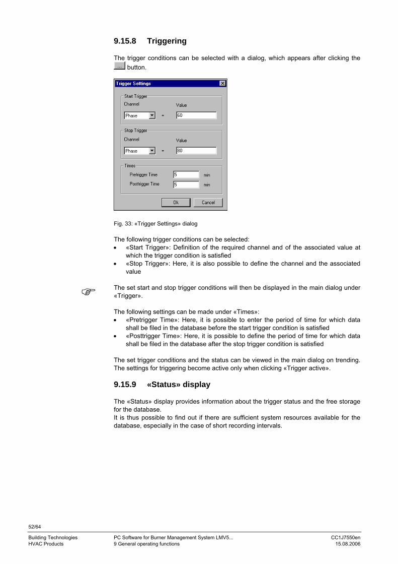
9.15.8 Triggering The trigger conditions can be selected with a dialog, which appears after clicking the
button.
Fig. 33: «Trigger Settings» dialog The following trigger conditions can be selected: • «Start Trigger»: Definition of the required channel and of the associated value at
which the trigger condition is satisfied • «Stop Trigger»: Here, it is also possible to define the channel and the associated
value
The set start and stop trigger conditions will then be displayed in the main dialog under «Trigger». The following settings can be made under «Times»: • «Pretrigger Time»: Here, it is possible to enter the period of time for which data
shall be filed in the database before the start trigger condition is satisfied • «Posttrigger Time»: Here, it is possible to define the period of time for which data
shall be filed in the database after the stop trigger condition is satisfied The set trigger conditions and the status can be viewed in the main dialog on trending. The settings for triggering become active only when clicking «Trigger active». 9.15.9 «Status» display The «Status» display provides information about the trigger status and the free storage for the database. It is thus possible to find out if there are sufficient system resources available for the database, especially in the case of short recording intervals.
52/64
Building Technologies PC Software for Burner Management System LMV5... CC1J7550en HVAC Products 9 General operating functions 15.08.2006
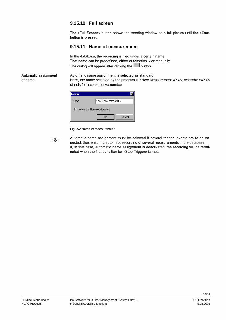
9.15.10 Full screen The «Full Screen» button shows the trending window as a full picture until the «Esc» button is pressed. 9.15.11 Name of measurement In the database, the recording is filed under a certain name. That name can be predefined, either automatically or manually. The dialog will appear after clicking the button. Automatic name assignment is selected as standard. Automatic assignment
of name Here, the name selected by the program is «New Measurement XXX», whereby «XXX» stands for a consecutive number.
Fig. 34: Name of measurement
Automatic name assignment must be selected if several trigger events are to be ex-pected, thus ensuring automatic recording of several measurements in the database. If, in that case, automatic name assignment is deactivated, the recording will be termi-nated when the first condition for «Stop Trigger» is met.
53/64
Building Technologies PC Software for Burner Management System LMV5... CC1J7550en HVAC Products 9 General operating functions 15.08.2006

9.16 Program update AZL5... 9.16.1 Introduction The program update is used for updating the program in the AZL5... This process writes a new binary file with the name extension «bin» into the memory of the AZL5... The major functions of the AZL5... are defined in that memory. In addition, the AZL5... has a memory in its microcontroller. That memory is a nonerasable read only memory and is used primarily for loading the update. The backup memory in the AZL5..., which is used for the parameters (EEPROM), will not be affected by the updating process. To do the program update, connect the AZL5... to the LMV5… system and the PC. The LMV5... system must be ready to operate. 9.16.2 Preparing the AZL5... Software loading must be prepared on the AZL5... To do this, select «Updating» from the menu and confirm. After selecting the access level (permitted from the service level), select menu item «Load SW from PC» and confirm. The AZL5... displays: «Load SW from PC» – «Start Process with Enter» – «Cancel with Esc». Press Enter to prepare the AZL5... for the process. Then, the AZL5... will display the following message (example): SW Update - MC:V01.00:V01.00 - FLASH:V01.70 - cancel: Left key. Here, you see the software versions of the microcontroller (MC) contained in the AZL5..., as well as the program memory (flash) prior to updating. If in doubt, the updating process can be aborted.
The structure of the MC’s software version is the following: The first number up to the colon gives directly the software version of the microcontrol-ler used. The second number after the colon is used for making the internal version check and must be identical to the first number. 9.16.3 Preparing the ACS450 On the ACS450, proceed as follows: Select «System LMV5x» → «Update AZL Flash» to make a file dialog appear. Select the file that contains the flash data, thus starting the programming process. 9.16.4 Programming process Just prior to starting the programming process, the following messages will appear on the display of the AZL5...: «clearing flash», then «programming» The ACS450 and AZL5... now show the progress with the current status.
54/64
Building Technologies PC Software for Burner Management System LMV5... CC1J7550en HVAC Products 9 General operating functions 15.08.2006

9.16.5 End of the programming process - check When the programming process is completed, the ACS450 will display the message «Transfer completed». When successfully programmed, the ACS450 will display «SW Update OK» and the updated SW version. Example: MC: V01.00: V01.00 - Flash: V01.80 - cancel: Left key In the event of fault, the AZL5... will display the following message: «error occurred» In that case, the cause of the fault is to be investigated. For example, one of the con-nectors of the serial line between AZL5... and PC may be lose. Rectify the fault and start programming again. When pressing the left button on the AZL5..., «System Test» will appear. Then, the AZL5... will operate with the new software.
55/64
Building Technologies PC Software for Burner Management System LMV5... CC1J7550en HVAC Products 9 General operating functions 15.08.2006
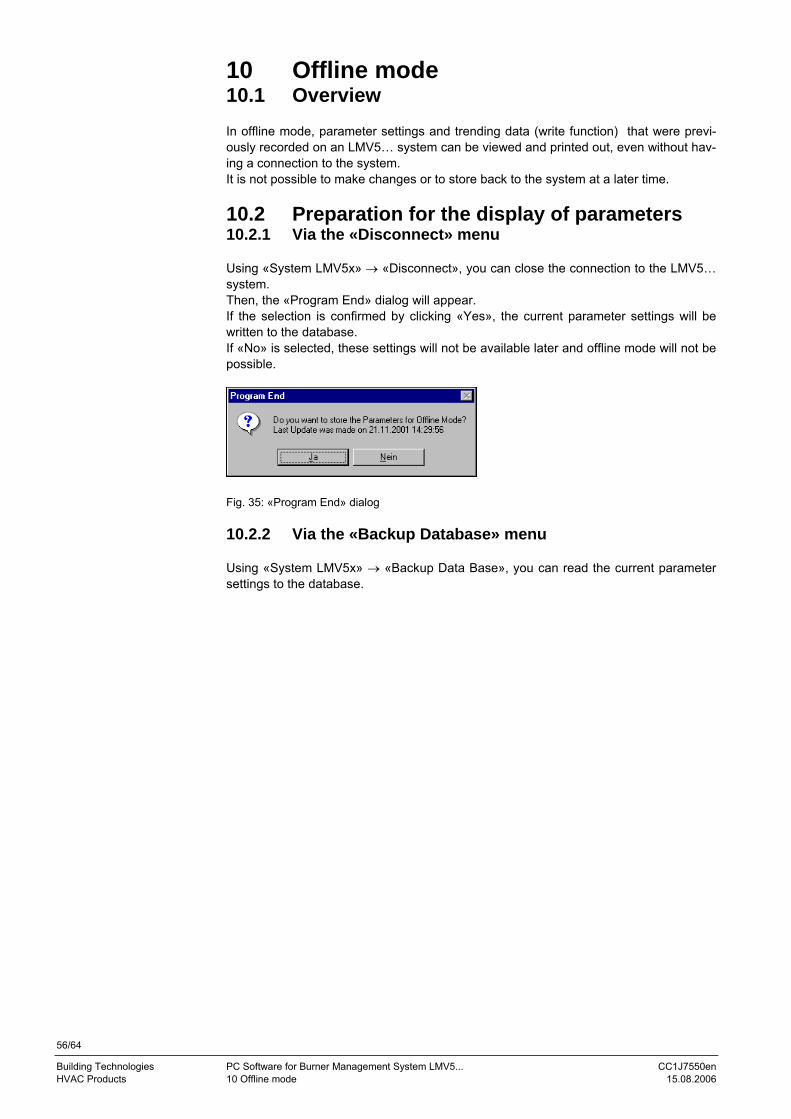
10 Offline mode 10.1 Overview In offline mode, parameter settings and trending data (write function) that were previ-ously recorded on an LMV5… system can be viewed and printed out, even without hav-ing a connection to the system. It is not possible to make changes or to store back to the system at a later time.
10.2 Preparation for the display of parameters 10.2.1 Via the «Disconnect» menu
Using «System LMV5x» → «Disconnect», you can close the connection to the LMV5… system. Then, the «Program End» dialog will appear. If the selection is confirmed by clicking «Yes», the current parameter settings will be written to the database. If «No» is selected, these settings will not be available later and offline mode will not be possible.
Fig. 35: «Program End» dialog 10.2.2 Via the «Backup Database» menu Using «System LMV5x» → «Backup Data Base», you can read the current parameter settings to the database.
56/64
Building Technologies PC Software for Burner Management System LMV5... CC1J7550en HVAC Products 10 Offline mode 15.08.2006
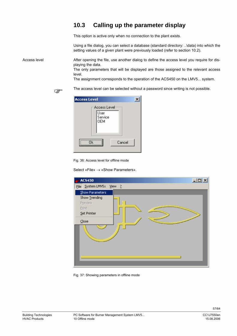
10.3 Calling up the parameter display This option is active only when no connection to the plant exists. Using a file dialog, you can select a database (standard directory: ..\data) into which the setting values of a given plant were previously loaded (refer to section 10.2). After opening the file, use another dialog to define the access level you require for dis-playing the data. The only parameters that will be displayed are those assigned to the relevant access level. The assignment corresponds to the operation of the ACS450 on the LMV5... system. The access level can be selected without a password since writing is not possible.
Fig. 36: Access level for offline mode Select «File» → «Show Parameters».
Fig. 37: Showing parameters in offline mode
Access level
57/64
Building Technologies PC Software for Burner Management System LMV5... CC1J7550en HVAC Products 10 Offline mode 15.08.2006
10.4 Control file for displaying and printing parameters To print parameters, they must be stored in a database first. These data can be shown and printed out later in offline mode. This requires a control file. That file specifies the parameters that will be output and the way they are formatted. It is thus possible to make individual printouts relating to the documentation. The control file also gives the names of the parameters. The parameter names can be taken from a file that exists on the installation CD (file name «para_name.xls» in directory «para_name»). Explanatory comments can be entered throughout the control file. These are identified by a semico-lon at the beginning of the line. Main section and print sections are identified by brack-ets «[ ]». The name of the control file is predefined and depends on the password level: • Enduser level (AB) tooldoku_AB.ini • Service level (HF) tooldoku_HF.ini • OEM level tooldoku_OEM.ini A sample file is filed in the program directory. This displays all available parameters of the relevant password level. This sample file can be used as a template for creating your specific control file. 10.4.1 Main section of file The main section of the file carries the name [Parameter]. The following key words are available: Version = xx.yy This information is mandatory. It gives the software version of
the AZL5... for which the control file is valid. Test = 1 If this value is given, the control file will be newly read in each
time the print preview is shown. This is useful when creating the control file. It is thus possible to check the file before everything is printed out. Apart from that, to speed up the display, this entry should not exist.
Section = <Name> The name to be selected is the print section. Example: [Parameter] Version = 1.70 Test = 1 Section01 = Title Section02 = Param_Gas_Oil Section03 = Title Section04 = Param_Gas Section05 = Title Section06 = Param-Oil
Sample file
58/64
Building Technologies PC Software for Burner Management System LMV5... CC1J7550en HVAC Products 10 Offline mode 15.08.2006

10.4.2 Print section Specify in the print section now how a parameter is output at a certain position on the print page. In addition, you can format the output by defining the font and different graphic objects. Some key words require the definition of coordinates and lengths. The reference point for the coordinates is the top left hand corner. All lengths are given in mm. The following key words are available: VariableX = Output of a parameter Parameter: X-coordinate, Y-coordinate Alignment: left-aligned = 0 middle = 1 right-aligned = 2 Size in mm Parameter number (see list) LinieX = Draws a line Parameter: starting point (X-coordinate, Y-coordinate)
end point (X-coordinate, Y-coordinate) RectangleX = Draws a rectangle Parameter: X-coordinate, Y-coordinate, width, height FontX = Sets font type Parameter: bold On / off = 0 / 1 Italics On / off = 0 / 1 underlined On / off = 0 / 1 reserved always 0 font name TextX = Delivers a fixed text with the selected font type Parameter: X-coordinate, Y-coordinate Alignment: left-aligned = 0 middle = 1 right-aligned = 2 Size in mm Text DateX = Output of the current (computer) date Parameter: X-coordinate, Y-coordinate Alignment: left-aligned = 0 middle = 1 right-aligned = 2 Size in mm GraphX = Output of a graph Parameter: X-coordinate, Y-coordinate, width, height Name of the graph: TabStufOel Table multistage operation TabModOel Table modulating operation oil TabModGas Table modulating operation gas GrafModOel Graph modulating operation oil GrafModGas Graph modulating operation gas O2
59/64
Building Technologies PC Software for Burner Management System LMV5... CC1J7550en HVAC Products 10 Offline mode 15.08.2006

PageX = Trigger page feed Parameter: 1st value: not used 2nd value: Y-coordinate with
screen display 3rd and 4th value: not used Example: [Title] Date0 = 170; 10;2 ; 5; Rectange0 = 10; 10; 180; 30; Text0 = 90; 25; 1; 10; parameter LMV5x [Parameter_Gas] Page1 = 0; 300; 0; 0; Font1 = 0; 0; 1; 0; Arial Text1 = 10; 40; 0; 5; parameter gas Font 12 = 0; 0; 0; 0; Arial Text12 = 10; 50; 0; 5; graph of fuel / air ratio control system Graph11 = 10; 50; 100; 130; GrafModGas; Text13 = 10; 150; 0; 5; prepurge time gas; Variable13 = 90; 150; 2; 5; GG_Time_TprepurgeGas
60/64
Building Technologies PC Software for Burner Management System LMV5... CC1J7550en HVAC Products 10 Offline mode 15.08.2006
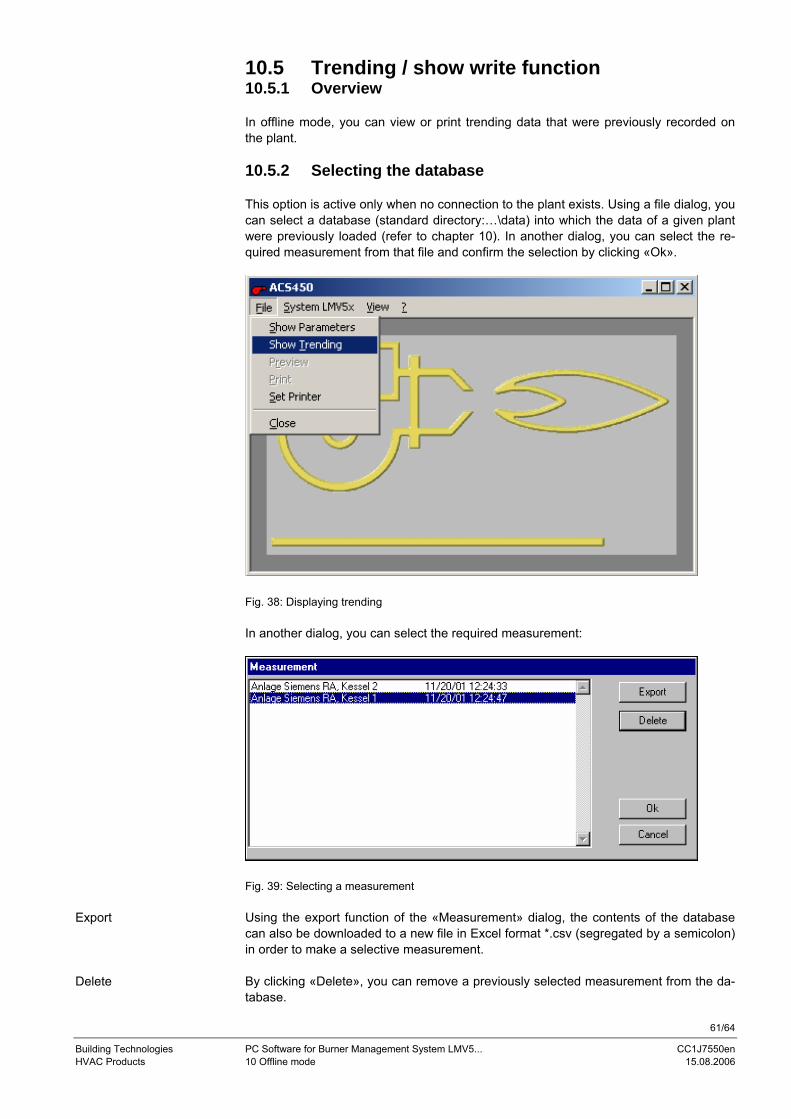
10.5 Trending / show write function 10.5.1 Overview In offline mode, you can view or print trending data that were previously recorded on the plant. 10.5.2 Selecting the database This option is active only when no connection to the plant exists. Using a file dialog, you can select a database (standard directory:…\data) into which the data of a given plant were previously loaded (refer to chapter 10). In another dialog, you can select the re-quired measurement from that file and confirm the selection by clicking «Ok».
Fig. 38: Displaying trending In another dialog, you can select the required measurement:
Fig. 39: Selecting a measurement Using the export function of the «Measurement» dialog, the contents of the database can also be downloaded to a new file in Excel format *.csv (segregated by a semicolon) in order to make a selective measurement.
Export
By clicking «Delete», you can remove a previously selected measurement from the da-tabase.
Delete
61/64
Building Technologies PC Software for Burner Management System LMV5... CC1J7550en HVAC Products 10 Offline mode 15.08.2006

10.5.3 Main dialog «Trending» After selecting the database and the measurement, the main dialog of trending will be displayed. 10.5.3.1 Settings in «Display» Here, you can make the basic settings for the X- and Y-coordinates by clicking the re-spective buttons. Several choices and zoom functions are available so that optimum displays can be achieved. 10.5.3.2 Trending diagram / write function For that purpose, call up the trending dialog first. Then, carry out the steps described in online mode (also refer to subsection 12). By clicking «Print», the diagram with the settings previously defined in «Display» will be output on the printer.
62/64
Building Technologies PC Software for Burner Management System LMV5... CC1J7550en HVAC Products 10 Offline mode 15.08.2006
11 Online help The ACS450 has an electronic help file (online help). When pressing the F1 key or when using the «Help» menu, the help text will appear, which is more or less identical to the information given in this documentation. These Operating Instructions are also available on the CD-ROM in the form of a PDF file. If required, the Operating Instructions can be installed on the PC. To read the documentation, Acrobat Reader of version 4 or higher is needed. If required, it can be downloaded from the Internet.
12 Fault handling 12.1 Faults during the parameter setting procedure If a fault occurs during the parameter setting procedure, make the following checks: •
•
•
•
Check if the parameters can be set in the current phase of the LMV5... system Example: The prepurge time cannot be changed during the «Startup sequence». Should the fault occur there, select a suitable phase of the basic unit LMV5... (e.g. lockout, standby) and repeat the process In the event of a transmission error due to a problem in the connecting line be-tween ACS450 and AZL5... (e.g. due to a lose connector), correct the cause of the fault and carry out a new upload from the LMV5… system by closing and opening the current parameter dialog. Then, check the parameter settings. If necessary, set the parameters again
If the parameters cannot be successfully set via the ACS450, repeat the parameter set-ting procedure directly on the AZL5... It should then be checked whether all associated components function correctly
12.2 Faults when opening a connection If a connection to the LMV5... system cannot be opened via the PC tool, make the fol-lowing checks:
Check if the line between PC tool and AZL5... is connected to the correct ports. The port to be used on the PC is the port that was specified for the installation pro-cedure. On the AZL5..., the port to be used is that under the front cover Check whether the cable used meets the specification (refer to section 7.1)
63/64
Building Technologies PC Software for Burner Management System LMV5... CC1J7550en HVAC Products 11 Online help 15.08.2006

Siemens Building Technologies HVAC Products GmbH © 2006 Siemens Building TechnologiesSubject to change!Berliner Ring 23
D – 76437 Rastatt Tel. +49 7222 598 279 Fax +49 7222 598 269 www.sbt.siemens.com
64/64
Building Technologies PC Software for Burner Management System LMV51... CC1J7550en HVAC Products 15.08.2006