second-order effects at microindentation of elastic polymers using sharp indenters
TRANSCRIPT

Materials and Design 32 (2011) 3645–3653
Contents lists available at ScienceDirect
Materials and Design
journal homepage: www.elsevier .com/locate /matdes
Technical Report
Second-order effects at microindentation of elastic polymers using sharp indenters
Yasir Kamran 1, Per-Lennart Larsson ⇑Department of Solid Mechanics, Royal Institute of Technology, SE-10044, Stockholm, Sweden
a r t i c l e i n f o a b s t r a c t
Article history:Received 3 December 2010Accepted 24 January 2011Available online 4 February 2011
0261-3069/$ - see front matter � 2011 Elsevier Ltd. Adoi:10.1016/j.matdes.2011.01.043
⇑ Corresponding author. Tel.: +46 8 790 7540; fax:E-mail address: [email protected] (P.-L. Larsson).
1 Present address: National Engineering & ScientifiDevelopment Directorate, Peshawar Road, Rawalpindi,
Sharp indentation of elastic polymers is investigated numerically using the finite element method. Largedeformation theory is relied upon for accuracy. Both cone and Vickers indentation is considered and inparticular, the study focuses on second-order effects on relevant indentation quantities in the micro-indentation regime. The second-order effects include indenter tip roundness, friction and also, forgenerality, effects due to different values on the included angle of the cone indenter, a. It is shown thatfrictional effects as well as effects due to indenter tip roundness are small at cone indentation but frictioncan substantially influence the results in case of Vickers indentation. The latter feature is most likely dueto frictional effects at the ridges of the indenter and as such behavior is not accurately described usingconventional theory of friction, a numerical approach for this purpose is discussed.
� 2011 Elsevier Ltd. All rights reserved.
1. Introduction
Sharp indentation or hardness tests, associated with namessuch as Knoop, Vickers and Berkovich, have, for a long time, beenused to characterize conventional engineering materials, such asmetals and alloys. In recent years, such tests have received increas-ing attention due to the development of new experimental devices,such as the nanoindenter [1], enabling the determination of thematerial properties from extremely small samples. Another reasonfor the renewed interest in indentation testing is the fact that, formany new engineering materials such as ceramics, a standard uni-axial test often fails to deliver reliable results and, accordingly,indentation is the only alternative for material characterization.Furthermore, indentation is a very convenient tool for determiningthe material properties of thin films or strings in ready-to-useengineering devices. The most important quantities given by anindentation test are the hardness H, here and in the sequel, inter-preted as the mean contact pressure, the contact area A or, alterna-tively, the relation between indentation load, P, and indentationdepth, h, during loading as well as unloading. These quantitiescan then be used to determine the constitutive properties of thematerial by taking advantage of results from earlier theoreticaland experimental analyses by, for example, Tabor [2], Johnson[3], Larsson [4], and Oliver and Pharr [5].
Most commonly, indentation testing involves both elastic andplastic deformation. This being in particular so at sharp indenta-tion where the absence of a characteristic length in the problem
ll rights reserved.
+46 8 411 2418.
c Commission, Technology &Pakistan.
indicates that plasticity enters the problem immediately at contact(the exception being indentation of materials described by non-local plasticity where a characteristic length parameter is intro-duced from the constitutive equation, cf. e.g. [6]). There are,however, quite a few situations of practical importance wherepurely elastic deformation results, pertinent to sharp indentation,are of immediate significance. This concerns in particular sharpindentation of highly elastic polymers, where plastic deformationis negligible, but also when it comes to analytical modeling ofunloading at indentation. The latter issue is of interest when inden-tation is used in order to determine the elastic properties of amaterial, cf. e.g. Oliver and Pharr [5].
Regardless of whether or not both elastic and/or plastic defor-mation is present at sharp indentation the relation between nor-mal indentation load and indentation depth can always bedescribed as
P � h2: ð1Þ
The relation (1) is valid when the dimensions of the contact areaare small compared to the dimensions of the indented material andno length quantity is introduced from, for example, the constitu-tive equation. This means that (1) holds at, for example, Hookeanelasticity and classical Mises plasticity. For the case of cone inden-tation of an elastic half-space, Sneddon [7] derived the explicitrelationship
P ¼ 2Eh2 tanða=2Þ=ðpð1� m2ÞÞ; ð2Þ
where E and m are Young’s modulus and Poisson’s ratio respectivelyof the half-space and a is the included angle of the conical indenter.Numerous related formulas for other types of indenters and consti-tutive equations have been presented, cf. e.g. [3,8,9], but are notshown here for brevity.
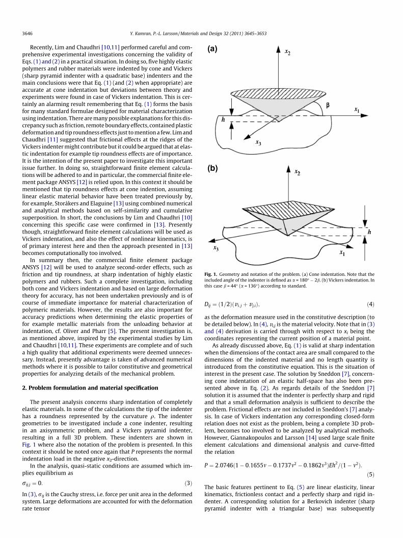
Fig. 1. Geometry and notation of the problem. (a) Cone indentation. Note that theincluded angle of the indenter is defined as a = 180� � 2b. (b) Vickers indentation. Inthis case b = 44� (a = 136�) according to standard.
3646 Y. Kamran, P.-L. Larsson / Materials and Design 32 (2011) 3645–3653
Recently, Lim and Chaudhri [10,11] performed careful and com-prehensive experimental investigations concerning the validity ofEqs. (1) and (2) in a practical situation. In doing so, five highly elasticpolymers and rubber materials were indented by cone and Vickers(sharp pyramid indenter with a quadratic base) indenters and themain conclusions were that Eq. (1) (and (2) when appropriate) areaccurate at cone indentation but deviations between theory andexperiments were found in case of Vickers indentation. This is cer-tainly an alarming result remembering that Eq. (1) forms the basisfor many standard formulae designed for material characterizationusing indentation. There are many possible explanations for this dis-crepancy such as friction, remote boundary effects, contained plasticdeformation and tip roundness effects just to mention a few. Lim andChaudhri [11] suggested that frictional effects at the ridges of theVickers indenter might contribute but it could be argued that at elas-tic indentation for example tip roundness effects are of importance.It is the intention of the present paper to investigate this importantissue further. In doing so, straightforward finite element calcula-tions will be adhered to and in particular, the commercial finite ele-ment package ANSYS [12] is relied upon. In this context it should bementioned that tip roundness effects at cone indention, assuminglinear elastic material behavior have been treated previously by,for example, Storåkers and Elaguine [13] using combined numericaland analytical methods based on self-similarity and cumulativesuperposition. In short, the conclusions by Lim and Chaudhri [10]concerning this specific case were confirmed in [13]. Presentlythough, straightforward finite element calculations will be used asVickers indentation, and also the effect of nonlinear kinematics, isof primary interest here and then the approach presented in [13]becomes computationally too involved.
In summary then, the commercial finite element packageANSYS [12] will be used to analyze second-order effects, such asfriction and tip roundness, at sharp indentation of highly elasticpolymers and rubbers. Such a complete investigation, includingboth cone and Vickers indentation and based on large deformationtheory for accuracy, has not been undertaken previously and is ofcourse of immediate importance for material characterization ofpolymeric materials. However, the results are also important foraccuracy predictions when determining the elastic properties offor example metallic materials from the unloading behavior atindentation, cf. Oliver and Pharr [5]. The present investigation is,as mentioned above, inspired by the experimental studies by Limand Chaudhri [10,11]. These experiments are complete and of sucha high quality that additional experiments were deemed unneces-sary. Instead, presently advantage is taken of advanced numericalmethods where it is possible to tailor constitutive and geometricalproperties for analyzing details of the mechanical problem.
2. Problem formulation and material specification
The present analysis concerns sharp indentation of completelyelastic materials. In some of the calculations the tip of the indenterhas a roundness represented by the curvature q. The indentergeometries to be investigated include a cone indenter, resultingin an axisymmetric problem, and a Vickers pyramid indenter,resulting in a full 3D problem. These indenters are shown inFig. 1 where also the notation of the problem is presented. In thiscontext it should be noted once again that P represents the normalindentation load in the negative x2-direction.
In the analysis, quasi-static conditions are assumed which im-plies equilibrium as
rij;j ¼ 0: ð3Þ
In (3), rij is the Cauchy stress, i.e. force per unit area in the deformedsystem. Large deformations are accounted for with the deformationrate tensor
Dij ¼ ð1=2Þðv i; j þ v j;iÞ; ð4Þ
as the deformation measure used in the constitutive description (tobe detailed below). In (4), vi,j is the material velocity. Note that in (3)and (4) derivation is carried through with respect to xi being thecoordinates representing the current position of a material point.
As already discussed above, Eq. (1) is valid at sharp indentationwhen the dimensions of the contact area are small compared to thedimensions of the indented material and no length quantity isintroduced from the constitutive equation. This is the situation ofinterest in the present case. The solution by Sneddon [7], concern-ing cone indentation of an elastic half-space has also been pre-sented above in Eq. (2). As regards details of the Sneddon [7]solution it is assumed that the indenter is perfectly sharp and rigidand that a small deformation analysis is sufficient to describe theproblem. Frictional effects are not included in Sneddon’s [7] analy-sis. In case of Vickers indentation any corresponding closed-formrelation does not exist as the problem, being a complete 3D prob-lem, becomes too involved to be analyzed by analytical methods.However, Giannakopoulos and Larsson [14] used large scale finiteelement calculations and dimensional analysis and curve-fittedthe relation
P ¼ 2:0746ð1� 0:1655m� 0:1737m2 � 0:1862m3ÞEh2=ð1� m2Þ:
ð5Þ
The basic features pertinent to Eq. (5) are linear elasticity, linearkinematics, frictionless contact and a perfectly sharp and rigid in-denter. A corresponding solution for a Berkovich indenter (sharppyramid indenter with a triangular base) was subsequently

Table 1Material properties of the elastic solids and the indenter material.
Material Modulus of elasticity, E Poisson ratio, m
Elastic solids Natural rubber 3.3 MPa 0.49Neoprene 8.15 MPa 0.5PDMS (1:10) 1.55 MPa 0.5PDMS (1:20) 0.65 MPa 0.5PDMS (1:30) 0.3 Mpa 0.5
Rigidindenter
Tungstencarbide
605 GPa 0.26
Fig. 2. FEM mesh used in the simulations of cone indentation. (a) Complete mesh.(b) Details close to the region of contact.
Y. Kamran, P.-L. Larsson / Materials and Design 32 (2011) 3645–3653 3647
presented by Larsson et al. [15] but is left out for brevity (the resultsin [15] have also been verified by recent FEM studies by Xu and Li[16]).
As been emphasized above, the relations (2) and (5) are bothpertinent to an analysis based on linear kinematics. At elastoplasticindentation, both for spherical and sharp indenters, it has beenshown that large deformation effects can be substantial, cf. e.g.[17–19]. At purely elastic deformations, these effects are reportedto be less significant as for example Giannakopoulos et al. [14]and Larsson et al. [15] reported differences within a few percentbetween large deformation and small deformation results. Stillthough, there are differences between the two sets of results andaiming at high accuracy solutions it was thought advisable to in-clude nonlinear kinematics in the present analysis.
It goes without saying that the indenter tip can never be per-fectly sharp in a practical situation. As a consequence, the initialpart of the load–displacement curve does not follow Eq. (1) as,for one thing, self-similarity is lost due to the presence of a charac-teristic length. The previously mentioned theoretical/numerical re-sults by Storåkers and Elaguine [13] indicate that tip roundnesseffects are small at cone indentation but a similar analysis perti-nent to Vickers indentation was not presented. Correspondingexperimental results by Lim and Chaudhri [10] for cone indenta-tion confirmed the conclusions made by Storåkers and Elaguine[13] but in a follow-up article Lim and Chaudhri [11] showed thatat Vickers indentation of highly experimental materials, not onlydid the P–h-curves deviate from theoretical predictions, cf. (2)and (5), but also from the functional form in Eq. (1). As already ex-plained above, Lim and Chaudhri [11] explained this feature withfrictional effects at the ridges of the Vickers indenter. This is indeeda plausible explanation but any decisive theoretical argument forthe results was not presented as the analysis by Lim and Chaudhri[11] was completely experimental. As many previous numericalinvestigations have indicated that, when global indentation prop-erties are at issue, frictional effects are small, cf. e.g. [20,21], it iscertainly of interest to explore alternative explanations to this dis-crepancy. In doing so, indenter tip imperfection is an obvious can-didate and its quantification will be studied presently. However, itgoes without saying that also frictional effects are accounted for inthe numerical calculations.
In the present study, tip imperfections are introduced by a sin-gle parameter, i.e. the tip is assumed spherical with the roundnessdescribed by the radius of curvature q. Two representative valueswere studied, cf. e.g. Lim and Chaudhri [10], namely
q ¼ 30;60 lm: ð6Þ
The explicit values on the curvature q suggest that tip imperfectionscan be of importance in the nano and microindentation regime.Accordingly, for a complete understanding indentation depths upto 400 lm were studied in the numerical simulations.
It remains then to discuss the constitutive specification and theexplicit values on the related material properties. As large defor-mations were accounted for a hypoelastic formulation of Hooke’slaw was relied upon yieldingDrij ¼ ðE=ð1þ mÞÞðdikdjl þ ðm=ð1� 2mÞÞdijdklÞDkl: ð7Þ
In (7) Drij is the objective Jaumann rate of the Cauchy stress.Explicit values on E and m for the materials investigated are shownin Table 1. The materials were chosen for comparative reasons asthey were included in the investigations by Lim and Chaudhri[10,11] with no plastic deformation at all present at sharp indenta-tion. In this context, it should be mentioned that in the simulations,the sharp indenter was modeled as an elastic material with a veryhigh value on the elastic stiffness. Explicit values, pertinent to tung-sten, for the indenter material are also shown in Table 1 and indi-cate that the indenter in practice can be considered as a rigid body.
3. Numerical analysis
In the last two decades the number of finite element analyses ofsharp indentation testing has increased enormously, cf. e.g. [4,14–16,22–25] (just to mention a few), and can now be considered as astandard method for numerical investigation of such problems.Such analyses include both 2D and 3D problems as well as differentforms of constitutive behavior (elastic, various elastoplastic modelsand many others). Accordingly, in the presentation of the presentnumerical approach below only the essential details of the analysiswill be discussed.
Cone indentation was simulated using the finite element soft-ware ANSYS [12] and accounting for large deformation effects. Axi-symmetric eight-noded elements were used to model the elastichalf-space and accordingly, the displacements were approximatedby quadratic functions within each element. The finite elementmesh is shown in Fig. 2 and a total of 14,404 elements were usedto model the elastic half-space. The domain size of the elastichalf-space was adjusted according to the maximum indentationdepth. In the simulations the maximum indentation depth waslimited to 400 lm and the outer boundaries of the elastic half-space were kept 50 times the maximum indentation depth so thatthe region of interest should be insensitive to the actions imposedat the far-field boundaries. Therefore the domain size of the

3648 Y. Kamran, P.-L. Larsson / Materials and Design 32 (2011) 3645–3653
half-space was kept to 20 mm by 20 mm. A very fine mesh divisionof elements close to the indenter tip was employed to achieve agood resolution of the contact area and the element size was grad-ually increased with distance further away from the contact regionto save computing time and to gain sufficient accuracy in the areaof interest. The lower boundary of the half-space was prohibited tomove in the transversal direction (y-direction in Fig. 2) while zerodisplacements in the radial direction (x-direction in Fig. 2) wereenforced at the far-field boundary on the right side in Fig. 2. Theupper surface was free outside the contact region. The conicaland (almost) rigid indenter was also modeled using axisymmetriceight-noded elements and was enforced to move in the normaldirection to the half-space, i.e. zero tangential displacements, withthe included angle of the indenter, a, being allowed to vary for gen-erality. The tip imperfections are as already mentioned assumedspherical and can accordingly be modeled exactly as quadratic ele-ments are used. Contact was modeled using so called flexible-to-flexible surface-to-surface contact, ANSYS [12], between the elastichalf-space and the indenter with contact elements overlying theelements of the free surface at y = 0 (in Fig. 2). Friction was mod-eled in a standard manner using Coulomb friction.
The accuracy of the so described numerical approach waschecked by comparing the present results with the analytical onesby Sneddon [7] in Eq. (2). The two sets of results proved to be close(explicit results are shown in Section 4 below) even though FEMvalues are consistently slightly higher. This, however, is most likelydue to large deformation effects and was also reported by Xu and Li[16] at similar circumstances. Indeed, when the present valueswere compared to corresponding ones in [16] almost perfect agree-ment was found giving further confidence as regards the accuracyof the numerical scheme.
The analysis of the Vickers indentation test follows closely theone described above for cone indentation. The main difference isof course that in this case full 3D simulations have to be performed.Accordingly, the half-space was modeled using 17,010 eight-nodedbrick elements with the displacements approximated by linearfunctions within each element. Quadratic elements were not usedin the 3D analysis as this would increase the computational timesignificantly. The finite element mesh is not shown for brevity asit is essentially the same as the one shown in Fig. 2 but extended45� in the circumferential direction (note that advantage is takenof the eightfold symmetry of the problem). Also in this case, largedeformation effects were accounted for. The accuracy of the FEManalysis of the Vickers test will be discussed below in Section 4.
4. Results and discussion
In the presentation below, results pertinent to sharp indenta-tion of purely elastic solids are discussed. The discussion is dividedinto. The first part concerns cone indentation and the second oneconcerns Vickers indentation.
4.1. Cone Indentation
In the analysis, the effect of indenter tip roundness, frictional ef-fects as well as effects due to different values on the included angleof the cone indenter, a, are all investigated for generality.
Material characteristics of the studied materials are as previ-ously mentioned listed in Table 1. As regards explicit values onother parameters the included angle of the cone indenter, a, takeson the values
a ¼ 120�;136�;140:6�; ð8Þ
being of most practical interest in an experimental situation, whilethe coefficient of friction, l, varied according to
l ¼ 0 ðfrictionless contactÞ;0:01;0:05;0:1: ð9Þ
Furthermore, the spherical cap of the indenter tip had the values onthe radius of curvature according to (6).
In order to determine the accuracy of the numerical approachused here it seems appropriate to start the presentation of explicitresults by showing a comparison between presently derived re-sults and earlier analytical and numerical ones. This was discussedbriefly above in Section 3 but here detailed results for cone inden-tation are shown in Fig. 3 where presently derived values are com-pared with corresponding analytical results from Eq. (2) and FEMresults by Xu and Li [16]. In order to facilitate a direct comparisonwith the results by Xu and Li [16] the material constants used inthese simulations were
E ¼ 72 GPa; m ¼ 0:17: ð10Þ
Frictionless contact was assumed and the indenter tip is perfectlysharp with the included angle of the indenter a = 140.6�. It is obvi-ous from the curves shown in Fig. 3 that the present FEM resultsand the results from Sneddon [7] (Eq. (2)) are close even thoughthe numerical ones are consistently higher. However, as mentionedrepeatedly above, Eq. (7) is based on small strain theory while inboth numerical studies large deformation effects are included. Asthe two sets of results based on FEM simulations essentially coin-cide, it can be concluded that, first of all, the difference betweentheory and numerics is due to the fact that a simplified kinematicaldescription is used in the theoretical analysis, and, secondly, thatresults of high accuracy can be expected from the presently usednumerical approach. It should be noted in passing that both numer-ical solutions are well-fitted to a quadratic (power-law) relationaccording to Eq. (1) as also shown in Fig. 3. This matter will alsobe discussed directly below.
Representative explicit results for cone indentation, using a per-fectly sharp indenter with a = 140.6�, of the materials described inTable 1 are shown in Fig. 4. It should be emphasized that no funda-mental qualitative differences between the present FEM and theanalytical results according to Eq. (2) were found for any of the fivematerials and accordingly only values for one material at a time areshown explicitly in the figures below (even though FEM results forall materials are depicted in Fig. 4 for generality). The similaritiesbetween the solutions come as no surprise as the analysis concernssharp indentation of purely elastic materials that take on almostidentical values on Poisson’s ratio. Indeed, the inclusion of all fivematerials in Table 1 in the investigation was only made in orderto achieve a complete comparison with the experimental resultsby Lim and Chaudhri [10,11]. As regards the results in Fig. 4 itcan be observed that the agreement between theory and numericsis even better for neoprene than for the material defined in Eq. (10)with explicit values shown in Fig. 3. Obviously, it can be concludedthat incompressibility suppresses effects due to large deforma-tions. Furthermore, it can also be noted that in this case the FEMresults are perfectly fitted to a quadratic (power-law) relationaccording to Eq. (1). From purely theoretical arguments this holdstrue for indentation of a half-space and the results shown in Fig. 4indicate further that high accuracy predictions can be expectedfrom the present numerical approach.
So far only results pertinent to a perfectly sharp indenter witha = 140.6� have been presented. Additional calculations were per-formed for values on a according to Eq. (8). From the results itcan be concluded that a decrease of the included angle increasedthe difference between the numerics and theory, as shown inFig. 5 for a cone indenter with a = 120�, at least so for values ona according to Eq. (8). It should be mentioned that additional cal-culations for a = 90� and a = 60� confirmed this trend. However,such values on a increased the numerical difficulties significantlyand high accuracy of results cannot be ensured. Indeed, even at

Fig. 3. Cone indentation (a = 140.6�) of the material in Eq. (10). Normal indentation load, P, as function of indentation depth, h, at frictionless contact and sharp indenter tip.Comparison between present FEM results, FEM results by Xu and Li [16] and analytical results by Sneddon [7] according to Eq. (2).
Fig. 4. Cone indentation (a = 140.6�) of the materials in Table 1. Normal indentation load, P, as function of indentation depth, h, at frictionless contact and sharp indenter tip.For the neoprene material a comparison is shown between (a) present FEM results and (b) analytical results by Sneddon [7] according to Eq. (2). FEM results for (c) rubber, (d)PDMS (1:10), (e) PDMS (1:20) and (f) PDMS (1:30).
Fig. 5. Cone indentation (a = 120�) of the neoprene material in Table 1. Normal indentation load, P, as function of indentation depth, h, at frictionless contact and sharpindenter tip. Comparison between present FEM results and analytical results by Sneddon [7] according to Eq. (2).
Y. Kamran, P.-L. Larsson / Materials and Design 32 (2011) 3645–3653 3649

3650 Y. Kamran, P.-L. Larsson / Materials and Design 32 (2011) 3645–3653
a = 120�, but not at a = 136� and a = 140.6�, a slight deviation fromthe quadratic relation in Eq. (1) is evident due to decreasingnumerical accuracy at increasingly sharp indenters. Consequently,almost all results presented in connection with cone indentation ispertinent to a cone indenter with a = 140.6� for which high accu-racy predictions have been secured as discussed above.
Frictional effects at cone indentation were then investigated fora perfectly sharp indenter with a = 140.6�. Explicit values on thecoefficient of friction according to Eq. (9) were used and in short,the results showed basically no effect from friction at all. Indeed,at the maximum indentation depth, 400 lm, the values on theindentation depth differed with less than 0.3% for the range of coef-ficient of friction values reported in Eq. (9). For this reason, explicitresults are not shown for brevity.
In Figs. 6 and 7 FEM results pertinent to tip roundness effectsare shown for values on the tip radius of curvature according toEq. (6) and a cone indenter with a = 140.6�. In Fig. 6 the resultsfor a sharp indenter are compared with corresponding ones for acone with tip roundness q = 30 lm. Evidently, there is essentiallyno difference between the two sets of results and, indeed, this isalso true for a larger value on the tip roundness, q = 60 lm, asshown in Fig. 7. Accordingly, even though tip imperfections areconsidered the functional form in Eq. (1) still holds in an accuratemanner and as a consequence, the second-order polynomial fitpresented in Figs. 6 and 7 has a quadratic term that is completelydominating. This polynomial fit is, however, presented here as anintroduction to the Vickers indentation results discussed below.
It can be concluded then, that second-order effects from frictionand tip imperfection are essentially negligible at cone indentation.This is further underlined by the fact that results given by the pres-ent FEM analysis agrees very well with the analytical results bySneddon [7] (assuming frictionless contact and a perfectly sharptip) as well as with the experimental results by Lim and Chaudhri[10]. In particular so at incompressible (or nearly incompressible)elastic behavior in which case large deformation effects are verymuch suppressed.
4.2. Vickers indentation
Vickers indentation was then investigated in the same spirit aswas done for cone indentation. In this case though, tip roundnesseffects was left out from the analysis as it was rigorously shownabove that such effects are not of importance in the present situa-tion and it is likely that this feature is independent of the indentergeometry. Frictional effects, however, are obviously dependent onstress field characteristics and are accordingly included in the pres-ent analysis of the Vickers test. Before any further discussion about
Fig. 6. Cone indentation (a = 140.6�) of the PDMS (1:20) material in Table 1. NormaComparison between present FEM results for a sharp indenter tip and for an indenter wcomplete second-order polynomial.
this matter it seems appropriate to first consider previous and per-tinent results in connection with the present FEM analysis. In doingso present FEM results are compared with corresponding ones byGiannakopoulos et al. [14] as reported in Eq. (5). The outcome ofthis comparison is depicted in Fig. 8 and it is obvious that thereis good agreement between the two sets of numerical results, inparticular so when remembering that Eq. (5) is based on smallstrain theory and Giannakopoulos et al. [14] clearly states thatlarge strain results are consistently higher (without showing anyquantitative results). It goes almost without saying that both solu-tions show excellent agreement with a quadratic relation accord-ing to Eq. (1). It should be noted that, as already pointed out forexperimental results by Lim and Chaudhri [11], there is no goodagreement with the FEM results and the analytical solution bySneddon [7] according to Eq. (2). This was not to be expectedthough as Eq. (2) is pertinent to cone indentation but the differ-ence, as reported in Fig. 9, is perhaps surprisingly large. In Fig. 9a second-order polynomial fit to the FEM solution is presentedbut again, this is intended for future discussions below and as inFigs. 6 and 7 the quadratic term is completely dominating.
The results depicted in Figs. 8 and 9 essentially indicate that thepresent numerical approach is sound (also at 3D indentation) andthat in the present purely elastic situation cone indentation resultscannot be directly used to model 3D sharp indentation in an accu-rate manner. This is indeed interesting results but it is likely thatthe results shown in Fig. 10 are of more fundamental importance.In Fig. 10 present FEM results for natural rubber are compared withcorresponding experimental Vickers indentation results by Limand Chaudhri [11]. It can be noted first of all that, in contrast tothe situation at cone indentation reported above, there are largedifferences between the two sets of results and, secondly, thatthe experimental ones are not accurately fitted to a quadratic func-tion according to Eq. (1). Instead, also indicated in Fig. 10, it is nec-essary to use a complete second-order polynomial in order toachieve an accurate curve-fit. In this context it should be notedthat the influence from the linear term (in the second-order poly-nomial), pertinent to the experimental results, is substantial. Itshould be mentioned that the results in Fig. 10 are valid for naturalrubber as defined in Table 1. According to Lim and Chaudhri [11],this material shows the most pronounced deviation from the func-tional form of Eq. (1) but the effect is present in all sets of experi-mental results pertinent to the materials in Table 1. Furthermore,in the calculations it is assumed that the Young’s modulus of rub-ber is 3.3 MPa, as determined by Lim and Chaudhri [10], while in[11], a Young’s modulus of 2.45 MPa is reported. This suggests thatthe difference between experimental results and FEM results iseven greater than what is shown in Fig. 10.
l indentation load, P, as function of indentation depth, h, at frictionless contact.ith tip roundness q = 30 lm. Only results for rounded tip indenter are fitted to the

Fig. 7. Cone indentation (a = 140.6�) of the PDMS (1:20) material in Table 1. Normal indentation load, P, as function of indentation depth, h, at frictionless contact.Comparison between present FEM results for indenters with tip roundness q = 30 lm and q = 60 lm. Only results for tip roundness q = 60 lm are fitted to the completesecond-order polynomial.
Fig. 8. Vickers indentation of the neoprene material in Table 1. Normal indentation load, P, as function of indentation depth, h, at frictionless contact and sharp indenter tip.Comparison between present FEM results and numerical results by Giannakopoulos et al. [14] according to Eq. (5).
Fig. 9. Vickers indentation of the neoprene material in Table 1. Normal indentation load, P, as function of indentation depth, h, at frictionless contact and sharp indenter tip.Comparison between present FEM results and analytical results by Sneddon [7] according to Eq. (2). Only FEM results are fitted to the complete second-order polynomial.
Y. Kamran, P.-L. Larsson / Materials and Design 32 (2011) 3645–3653 3651
The fact that the experimental Vickers indentation results byLim and Chaudhri [11] show a deviation from the functional formof Eq. (1) is intriguing as it indicates the existence of a characteris-tic length in the problem. This is further confirmed by the fact thataccording to Lim and Chaudhri [11] the experimentally determinedelastic hardness varies with the indentation depth while in theorythis quantity should be constant during an indentation test. There
are many possible effects that could introduce such a feature intothe indentation problem, for example effects from far-field bound-aries as well as deformation of the indenter. However, as the geo-metrical and material characteristics of the numerical analysiswere chosen in order to comply with the corresponding ones inthe experiments by Lim and Chaudhri [11], these effects can be ru-led out due to the good agreement between present results and

Fig. 10. Vickers indentation of the rubber material in Table 1. Normal indentation load, P, as function of indentation depth, h. In the FEM calculations, frictionless contact andsharp indenter tip is assumed. Comparison between present FEM results and experimental results by Lim and Chaudhri [11].
Fig. 11. Contact status at Vickers indentation of the neoprene material in Table 1. FEM results for sharp indenter tip. The indentation depth h = 400 lm and the coefficient offriction l = 0.1. Viewing in the negative x2-direction. Only 1/8 of the contact region is shown due to the symmetry of the problem.
3652 Y. Kamran, P.-L. Larsson / Materials and Design 32 (2011) 3645–3653
analytical or semi-empirical half-space solutions, cf. e.g. [7,14]. Infact, this also rules out any possible effects from inelastic deforma-tions. Furthermore, it has been shown above that tip roundness ef-fects are negligible in the present situation pertinent tomicroindentation. The remaining possible explanation to the devi-ation of the experimental results from Eq. (1) is frictional effectsbetween indenter and material. Presently, a large number ofsimulations of Vickers indentation were performed assumingCoulomb friction with values on the coefficient of friction accord-ing to Eq. (9) and in short, as was the case at cone indentation,there was no significant influence from friction on the load values.This issue has also been repeatedly studied for elastoplastic mate-rials, cf. e.g. Antunes et al. [26], and basically the present results areconfirmed indicating that Coulomb frictional effects are negligibleat Vickers indentation, at least so when global indentation quanti-ties are at issue.
It should be noted that in theory standard Coulomb frictioncannot explain the deviation of the experimental results by Limand Chaudhri [11] from the functional form of Eq. (1). However,the outcome of the simulations reported above show that frictionaleffects at the contact surface are very small and this suggestsstrongly that even if a more advanced frictional model includinga characteristic length scale is used, where for example the coeffi-cient of friction is load dependent, this would not explain the large
deviations between theory and experiments as depicted in Fig. 10.This is indeed also suggested by Lim and Chaudhri [11] as theyconclude that sliding at the contact interface is negligible in thepresent situation. This conclusion is supported by the presentFEM calculations with pertinent results for the contact statusshown in Fig. 11 indicating an almost non-existing sliding region.
Lim and Chaudhri [11] suggested that the behavior of the exper-imental curve depicted in Fig. 10 could be explained by frictionaleffects at the ridges of the Vickers indenter. At the ridges some fieldvariables are discontinuous and, furthermore, the stresses show asingular behavior. In such a situation a Coulomb frictional modelis not sufficient but instead, a high accuracy analysis requires bynecessity some advanced description of friction with nonlocal ef-fects included. This would introduce a characteristic length intothe mechanical problem which would explain the deviation ofthe experimental results in Fig. 10 from the functional form ofEq. (1). This feature, together with the fact that the present numer-ical analysis has shown that other possible mechanisms are non-significant, indicates strongly (even though indirectly) that Limand Chaudhri [11] are correct when they suggest that the behaviorof the experimental curve depicted in Fig. 10 could be explained byfrictional effects at the ridges of the Vickers indenter. The fact thatthis behavior is not present at cone indentation is a furtherindication in that direction.

Y. Kamran, P.-L. Larsson / Materials and Design 32 (2011) 3645–3653 3653
It was not attempted presently to introduce nonlocal frictionalmodels in the numerical scheme. Such an attempt would increasethe computational time and efforts substantially. Rememberingthat a qualitative explanation of second-order effects at sharp elas-tic indentation was the main objective, presently nonlocal descrip-tions were subsequently left out of the analysis. In the future, aquantitative analysis of the problem will be conducted and thennonlocal frictional models have to be implemented into thenumerical scheme by necessity. In commercial finite element pack-ages this can be achieved by using a so called ‘‘elastic slip’’ descrip-tion, cf. e.g. ABAQUS [27]. In the ‘‘elastic slip’’ description theCoulomb condition is not applied point wise but weighted overan area region with a so called mollifying function, Zhong [28].Specifically, the characteristic length of the area region then consti-tutes the length scale in the indentation problem.
As a final comment it should be mentioned that the present re-sults, although first and foremost intended for an investigation ofsharp elastic indentation problems, are relevant also for othertypes of contact problems. Typically, such problems would includefor example indentation methods for determination of the elasticstiffness of elastoplastic materials [5,29–32], scratching of poly-mers [33–36] and determination of residual stresses by sharpindentation [37–42] just to mention a few.
5. Conclusions
Second-order effects at sharp indentation of elastic polymershave been investigated numerically using the finite element meth-od. The second-order effects include indenter tip roundness, fric-tion and also, for generality, effects due to different values on theincluded angle of the cone indenter, a. Both cone and Vickersindentation were considered and the most important conclusionscan be summarized as follow:
� Large deformation theory must be relied upon for high accuracypredictions.� Frictional effects as well as effects due to indenter tip roundness
are small at cone indentation.� Friction can substantially influence the results in case of Vickers
indentation.� Frictional effects at Vickers indentation are most likely due to
friction at the ridges of the indenter as suggested by Lim andChaudhri [11].
The latter conclusion above suggests the need for a numericalanalysis based on a nonlocal frictional model. Such an approachwill be considered in future investigations.
References
[1] Pethica JB, Hutchings R, Oliver WC. Hardness measurements at penetrationdepths as small as 20 nm. Phil Mag 1983;A48:593–606.
[2] Tabor D. Hardness of metals. Cambridge: Cambridge University Press; 1951.[3] Johnson KL. The correlation of indentation experiments. J Mech Phys Solids
1970;18:115–26.[4] Larsson PL. On the mechanical behavior of global parameters in material
characterization by sharp indentation testing. J Test Eval 2004;32:310–21.[5] Oliver WC, Pharr GM. An improved technique for determining hardness and
elastic modulus using load and displacement sensing indentation experiments.J Mater Res 1992;7:1564–83.
[6] Fredriksson P, Larsson PL. Wedge indentation of thin films modeled by straingradient plasticity. Int J Solids Struct 2008;45:5556–66.
[7] Sneddon IN. The relation between load and penetration in the axisymmetricBoussinesq problem for a punch of arbitrary profile. Int J Eng Sci 1965;3:47–57.
[8] Larsson PL. Investigation of sharp contact at rigid plastic conditions. Int J MechSci 2001;43:895–920.
[9] Jang J, Lance MJ, Wen SQ, Tsui TY, Pharr GM. Indentation-induced phasetransformations in silicon: influences of load, rate and indenter angle on thetransformation behavior. Acta Mater 2005;53:1759–70.
[10] Lim YY, Chaudhri MM. Indentation of elastic solids with rigid cones. Phil Mag2004;84:2877–903.
[11] Lim YY, Chaudhri MM. Indentation of elastic solids with a rigid Vickerspyramid indenter. Mech Mater 2006;38:1213–28.
[12] ANSYS version 12. ANSYS, Inc.; 2009.[13] Storåkers B, Elaguine D. Hertz contact at finite friction and arbitrary profiles. J
Mech Phys Solids 2005;53:1422–47.[14] Giannakopoulos AE, Larsson PL, Vestergaard R. Analysis of Vickers indentation.
Int J Solids Struct 1994;31:2679–708.[15] Larsson PL, Söderlund E, Giannakopoulos AE, Rowcliffe DJ, Vestergaard R.
Analysis of Berkovich indentation. Int J Solids Struct 1996;33:221–48.[16] Xu ZH, Li X. Effects of indenter geometry and material properties on the
correction factor of Sneddon’s relationship for nanoindentation of elastic andelastic–plastic materials. Acta Mater 2008;56:1399–405.
[17] Mesarovic SD, Fleck NA. Frictionless indentation of dissimilar elastic–plasticspheres. Int J Solids Struct 2000;37:7071–91.
[18] Larsson PL. Modelling of sharp indentation experiments: some fundamentalissues. Phil Mag 2006;86:5155–77.
[19] Larsson PL. Similarity methods for analysing indentation contact problems –advantages and disadvantages. J Mater Proc Tech 2008;202:15–21.
[20] Carlsson S, Biwa S, Larsson PL. On frictional effects at inelastic contact betweenspherical bodies. Int J Mech Sci 2000;42:107–28.
[21] Mata M, Alcala J. The role of friction on sharp indentation. J Mech Phys Solids2004;52:145–65.
[22] Laursen TA, Simo JC. A study of the mechanics of microindentation usingfinite-elements. J Mater Res 1992;7:618–26.
[23] Giannakopoulos AE, Larsson PL. Analysis of pyramid indentation of pressuresensitive hard metals and ceramics. Mech Mater 1997;25:1–35.
[24] Larsson PL, Giannakopoulos AE. Tensile stresses and their implication tocracking at pyramid indentation of pressure-sensitive hard metals andceramics. Mater Sci Eng 1998;A254:268–81.
[25] Swaddiwudhipong S, Hua J, Tho KK, Liu ZS. Equivalency of Berkovich andconical load-indentation curves. Modell Simul Mater Sci Eng 2006;14:71–82.
[26] Antunes JM, Menezes LF, Fernandes JV. Three-dimensional numericalsimulation of Vickers indentation tests. Int J Solids Struct 2005;43:784–806.
[27] ABAQUS version 6.6. Theory manual. ABAQUS, Inc.; 2006.[28] Zhong ZH. Contact Problems with Friction. In: Proceedings of Numiform 89.
Balkema, Rotterdam; 1989.[29] Loubet JL, Georges JM, Marchesini O, Meille G. Vickers indentation curves of
magnesium-oxide (MgO). J Trib – Trans ASME 1984;106:43–8.[30] Doerner MF, Nix WD. A method for interpreting the data from depth-sensing
indentation instruments. J Mater Res 1986;1:601–9.[31] Lim YY, Chaudhri MM. Experimental investigations of the normal loading of
elastic spherical and conical indenters on to elastic flats. Phil Mag2003;83:3427–62.
[32] Lim YY, Chaudhri MM. Indentation of rigid cones into conical holes molded inelastic blocks. J Appl Phys 2005;98:073518.
[33] Bucaille JL, Felder E, Hochstetter G. Experimental and three-dimensional finiteelement study of scratch test of polymers at large deformations. J Trib – TransASME 2004;126:372–9.
[34] Wredenberg F, Larsson PL. Scratch testing of metals and polymers:experiments and numerics. Wear 2009;266:76–83.
[35] Wredenberg F, Larsson PL. Delamination of thin coatings at scratching:experiments and numerics. J Mech Mater Struct 2010;4:1041–62.
[36] Pelletier H, Gauthier C, Schirrer R. Influence of the friction coefficient on thecontact geometry during scratch onto amorphous polymers. Wear2010;268:1157–69.
[37] Lee YH, Kwon D. Measurement of residual-stress effect by nanoindentation onelastically strained (100) W. Scripta Mater 2003;49:459–65.
[38] Eriksson CL, Larsson PL, Rowcliffe DJ. Strain-hardening and residual stresseffects in plastic zones around indentations. Mater Sci Eng2003;A340:193–203.
[39] Lee YH, Kwon D. Estimation of biaxial surface stress by instrumentedindentation with sharp indenters. Acta Mater 2004;52:1555–63.
[40] Huber N, Heerens J. On the effect of a general residual stress state onindentation and hardness testing. Acta Mater 2008;56:6205–13.
[41] Heerens J, Mubarok F, Huber N. Influence of specimen preparation,microstructure anisotropy, and residual stresses on stress–strain curves ofrolled Al2024 T351 as derived from spherical indentation tests. J Mater Res2009;24:907–17.
[42] Larsson PL. On the mechanical behavior at sharp indentation of materials withcompressive residual stresses. Mater Des 2011;32:1427–34.