standard test method for microindentation hardness of materials1 · 2018-09-09 · designation: e...
TRANSCRIPT
Designation: E 384 – 05a
Standard Test Method forMicroindentation Hardness of Materials1
This standard is issued under the fixed designation E 384; the number immediately following the designation indicates the year oforiginal adoption or, in the case of revision, the year of last revision. A number in parentheses indicates the year of last reapproval. Asuperscript epsilon (e) indicates an editorial change since the last revision or reapproval.
This standard has been approved for use by agencies of the Department of Defense.
1. Scope
1.1 This test method covers determination of the microin-dentation hardness of materials, the verification of microinden-tation hardness testing machines, and the calibration of stan-dardized test blocks.
1.2 This test method covers microindentation tests madewith Knoop and Vickers indenters under test forces in the rangefrom 9.8 3 10-3 to 9.8 N ( 1 to 1000 gf ).
1.3 This test method includes an analysis of the possiblesources of errors that can occur during microindentation testingand how these factors affect the accuracy, repeatability, andreproducibility of test results.
NOTE 1—While Committee E04 is primarily concerned with metals, thetest procedures described are applicable to other materials.
1.4 This standard does not purport to address all of thesafety concerns, if any, associated with its use. It is theresponsibility of the user of this standard to establish appro-priate safety and health practices and determine the applica-bility of regulatory limitations prior to use.
2. Referenced Documents
2.1 ASTM Standards: 2
C 1326 Test Method for Knoop Indentation Hardness ofAdvanced Ceramics
C 1327 Test Method for Vickers Indentation Hardness ofAdvanced Ceramics
E 3 Methods of Preparation of Metallographic SpecimensE 7 Terminology Relating to MetallographyE 122 Practice for Choice of Sample Size to Estimate the
Average Quality for a Lot or ProcessE 140 Test Method for Hardness Conversion Tables for
MetalsE 175 Terminology of Microscopy
E 691 Practice for Conducting an Interlaboratory Study toDetermine the Precision of a Test Method
E 766 Practice for Calibrating the Magnification of a Scan-ning Electron Microscope
3. Terminology
3.1 Definitions—For definitions of terms used in this testmethod, see Terminology E 7.
3.2 Definitions of Terms Specific to This Standard:3.2.1 calibrating, v—determining the values of the signifi-
cant parameters by comparison with values indicated by areference instrument or by a set of reference standards.
3.2.2 Knoop hardness number, HK, n—an expression ofhardness obtained by dividing the force applied to the Knoopindenter by the projected area of the permanent impressionmade by the indenter.
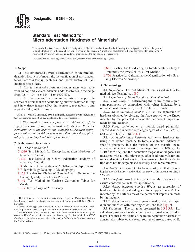
3.2.3 Knoop indenter, n—a rhombic-based pyramidal-shaped diamond indenter with edge angles of / A = 172° 308
and / B = 130° 08 (see Fig. 1).3.2.4 microindentation hardness test, n—a hardness test
using a calibrated machine to force a diamond indenter ofspecific geometry into the surface of the material beingevaluated, in which the test forces range from 1 to 1000 gf (9.83 10–3 to 9.8 N), and the indentation diagonal, or diagonals aremeasured with a light microscope after load removal; for anymicroindentation hardness test, it is assumed that the indenta-tion does not undergo elastic recovery after force removal.
NOTE 2—Use of the term microhardness should be avoided because itimplies that the hardness, rather than the force or the indentation size, isvery low.
3.2.5 verifying, v—checking or testing the instrument toassure conformance with the specification.
3.2.6 Vickers hardness number, HV, n—an expression ofhardness obtained by dividing the force applied to a Vickersindenter by the surface area of the permanent impression madeby the indenter.
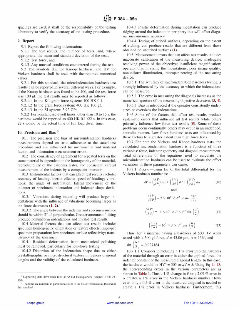
3.2.7 Vickers indenter, n—a square-based pyramidal-shapeddiamond indenter with face angles of 136° (see Fig. 2).
3.3 Formulae—The formulae presented in 3.3.1-3.3.4 fforcalculating microindentation hardness are based upon an idealtester. The measured value of the microindentation hardness ofa material is subjected to several sources of errors. Based on Eq
1 This test method is under the jurisdiction of ASTM Committee E04 onMetallography and is the direct responsibility of Subcommittee E04.05 on Micro-hardness.
Current edition approved August 15, 2005. Published September 2005. Origi-nally approved in 1969. Last previous edition approved in 2005 as E 384 – 05.
2 For referenced ASTM standards, visit the ASTM website, www.astm.org, orcontact ASTM Customer Service at [email protected]. For Annual Book of ASTMStandards volume information, refer to the standard’s Document Summary page onthe ASTM website.
1
Copyright © ASTM International, 100 Barr Harbor Drive, PO Box C700, West Conshohocken, PA 19428-2959, United States.
koopa group www.koopaco.com Tel: +9811 33366282

1-9, variations in the applied force, geometrical variationsbetween diamond indenters, and human errors in measuringindentation lengths can affect the calculated material hardness.The amount of error each of these parameters has on thecalculated value of a microindentation measurement is dis-cussed in Section 10.
3.3.1 For Knoop hardness tests, in practice, test loads are ingrams-force and indentation diagonals are in micrometers. TheKnoop hardness number is calculated using the following:
HK 5 1.000 3 103 3 ~P/Ap! 5 1.000 3 103 3 P/~cp 3 d2! (1)
or
HK 5 14229 3 P/d2 (2)
cp 5
tan S/ B2 D
2 tan S/ A2 D (3)
where:P = force, gf,d = length of long diagonal, µm,Ap = projected area of indentation, µm2,/ A = included longitudinal edge angle, 172° 308,
FIG. 1 Knoop Indenter
FIG. 2 Vickers Indenter
E 384 – 05a
2koopa group www.koopaco.com Tel: +9811 33366282

/ B = included transverse edge angle, 130° 08 (see Fig. 1),and
cp = indenter constant relating projected area of theindentation to the square of the length of the longdiagonal, ideally 0.07028.
NOTE 3—HK values for a 1-gf (9.8 3 10–3 N) test are contained inAppendix X6. To obtain HK values when other test forces are employed,multiply the HK value from Table X6.1 for the d value by the actual testforce, g.
3.3.2 The Knoop hardness, kgf/mm2 is determined as fol-lows:
HK 5 14.229 3 P1/d12 (4)
where:P1 = force, kgf, andd1 = length of long diagonal, mm.
3.3.3 The Knoop hardness reported with units of GPa isdetermined as follows:
HK 5 0.014229 3 P2/d22 (5)
where:P2 = force, N, andd2 = length of the long diagonal of the indentation, mm.
3.3.4 For the Vickers hardness test, in practice, test loads arein grams-force and indentation diagonals are in micrometres.The Vickers hardness number is calculated as follows:
HV 5 1.000 3 103 3 P/As 5 2.000 3 103 3 P sin~a/2!/d2 (6)
or
HV 5 1854.4 3 P/d2 (7)
where:P = force, gf,As = surface area of the indentation, µm2,d = mean diagonal length of the indentation, µm, anda = face angle of the indenter, 136° 08 (see Fig. 2).
NOTE 4—HV numbers for a 1-gf (9.8 3 10–3 N) test load are containedin Appendix X6. To obtain HV values when other test forces areemployed, multiply the HV value from Table X6.2 for the d value by theactual test force, g.
3.3.5 The Vickers hardness, kgf/mm2 is determined as fol-lows:
HV 5 1.8544 3 P1/d12 (8)
where:P1 = force, kgf, andd1 = length of long diagonal, mm.
3.3.6 The Vickers hardness reported with units of GPa isdetermined as follows:
HV 5 0.0018544 3 P2/d22 (9)
where:P2 = force, N, andd2 = length of the long diagonal of the indentation, mm.
4. Summary of Test Method
4.1 In this test method, a hardness number is determinedbased on the formation of a very small indentation by appli-
cation of a relatively low force, in comparison to ordinaryindentation hardness tests.
4.2 A Knoop or Vickers indenter, made from diamond ofspecific geometry is pressed into the test specimen surfaceunder an applied force in the range of 1 to 1000 gf using a testmachine specifically designed for such work.
4.3 The size of the indentation is measured using a lightmicroscope equipped with a filar type eyepiece, or other typeof measuring device (see Terminology E 175).
4.4 The Knoop hardness number is based upon the forcedivided by the projected area of the indentation. The Vickershardness number is based upon the force divided by the surfacearea of the indentation.
4.5 It is assumed that elastic recovery does not occur whenthe indenter is removed after the loading cycle, that is, it isassumed that the indentation retains the shape of the indenterafter the force is removed. In Knoop testing, it is assumed thatthe ratio of the long diagonal to the short diagonal of theimpression is the same (see 7.1.4) as for the indenter.
5. Significance and Use
5.1 Hardness tests have been found to be very useful formaterials evaluation, quality control of manufacturing pro-cesses and research and development efforts. Hardness, al-though empirical in nature, can be correlated to tensile strengthfor many metals, and is an indicator of wear resistance andductility.
5.2 Microindentation tests extend hardness testing to mate-rials too thin or too small for macroindentation tests. Microin-dentation tests allow specific phases or constituents and regionsor gradients too small for macroindentation testing to beevaluated.
5.3 Because the microindentation hardness will reveal hard-ness variations that may exist within a material, a single testvalue may not be representative of the bulk hardness.
6. Apparatus
6.1 Test Machine—The test machine must support the testspecimen and control the movement of the indenter into thespecimen under a preselected test force, and should have a lightoptical microscope to select the desired test location and tomeasure the size of the indentation produced by the test. Theplane of the surface of the test specimen must be perpendicularto the axis of the indenter and the direction of the forceapplication. The plane of the test surface of test specimen mustbe level in order to obtain usable information.
6.1.1 Force Application—The test machine shall be capableof applying the following forces:
6.1.1.1 The time from the initial application of the forceuntil the full test force is reached shall not exceed 10 s.
6.1.1.2 The indenter shall contact the specimen at a velocitybetween 15 and 70 µm/s.
6.1.1.3 The full test force shall be applied for 10 to 15 sunless otherwise specified.
6.1.1.4 For some applications it may be necessary to applythe test force for longer times. In these instances the tolerancefor the time of the applied force is 6 2 s.
6.1.2 Vibration Control—During the entire test cycle, thetest machine should be protected from shock or vibration. To
E 384 – 05a
3koopa group www.koopaco.com Tel: +9811 33366282

minimize vibrations, the operator should avoid contacting themachine in any manner during the entire test cycle.
6.2 Vickers Indenter—The Vickers indenter usually pro-duces a geometrically similar indentation at all test forces.Except for tests at very low forces that produce indentationswith diagonals smaller than about 25 µm, the hardness numberwill be essentially the same as produced by Vickers machineswith test forces greater than 1 kgf, as long as the material beingtested is reasonably homogeneous. For isotropic materials, thetwo diagonals of a Vickers indentation are equal in size.
6.2.1 The ideal Vickers indenter is a highly polished,pointed, square-based pyramidal diamond with face angles of136° 08. The effect that geometrical variations of these angleshave on the measured values of Vickers hardness are discussedin Section 10.
6.2.2 The four faces of the Vickers indenter shall be equallyinclined to the axis of the indenter (within 6 308) and shallmeet at a sharp point. The line of junction between oppositefaces (offset) shall be not more than 0.5 µm in length as shownin Fig. 2.
6.3 Knoop Indenter—The Knoop indenter does not producea geometrically similar indentation as a function of test force.Consequently, the Knoop hardness will vary with test force.Due to its rhombic shape, the indentation depth is shallower fora Knoop indentation compared to a Vickers indentation underidentical test conditions. The two diagonals of a Knoopindentation are markedly different. Ideally, the long diagonal is7.114 times longer than the short diagonal, but this ratio isinfluenced by elastic recovery. Thus, the Knoop indenter isvery useful for evaluating hardness gradients or thin coatings.
6.3.1 The Knoop indenter is a highly polished, pointed,rhombic-based, pyramidal diamond. The ideal included longi-tudinal edge angles are 172° 308 and 130° 08. The idealindenter constant, cp, is 0.07028. The effect that geometricalvariations of these angles have on the measured values ofKnoop hardness are discussed in Section 10.
6.3.2 The four faces of the Knoop indenter shall be equallyinclined to the axis of the indenter (within 6 308) and shallmeet at a sharp point. The line of junction between oppositefaces (offset) shall be not more than 1.0 µm in length forindentations greater than 20 µm in length, as shown in Fig. 1.For shorter indentations the offset should be proportionatelyless.
6.3.3 Indenters should be examined periodically and re-placed if they become worn, dulled, chipped, cracked orseparated from the mounting material.
6.4 Measuring Equipment—The test machine’s measuringdevice should report the diagonal lengths in 0.1 µm incrementsfor indentations with diagonals from 1 to 200 µm.
NOTE 5—This is the reported length and not the resolution of thesystem used for performing the measurements. As an example, if a lengthof 200 µm corresponds to 300 filar units or pixels, the correspondingcalibration constant would be 200/300 = 0.66666667. This value would beused to compute diagonal lengths, but the reported length would only bereported to the nearest 0.1 µm.
6.4.1 The optical portion of the measuring device shouldhave Köhler illumination (see Appendix X1).
6.4.2 To obtain maximum resolution, the measuring micro-scope should have adjustable illumination intensity, adjustablealignment and aperture and field diaphragms.
6.4.3 Magnifications should be provided so that the diago-nal can be enlarged to greater than 25 % but less than 75 % ofthe field width.
7. Test Specimen
7.1 For optimum accuracy of measurement, the test shouldbe performed on a flat specimen with a polished or otherwisesuitably prepared surface. The surface must be free of anydefects that could affect the indentation or the subsequentmeasurement of the diagonals. Conducting tests on non-planarsurfaces is not recommended. Results will be affected even inthe case of the Knoop test where the radius of curvature is inthe direction of the short diagonal.
7.1.1 In all tests, the indentation perimeter, and the inden-tation tips in particular, must be clearly defined in the micro-scope field of view.
7.1.2 The specimen surface should not be etched beforemaking an indentation. Etched surfaces can obscure the edge ofthe indentation, making an accurate measurement of the size ofthe indentation difficult. However, when determining the mi-croindentation hardness of an isolated phase or constituent, alight etch can be used to delineate the object of interest. Thequality of the required surface finish can vary with the forcesand magnifications used in microindentation hardness testing.The lighter the force and the smaller the indentation size, themore critical is the surface preparation. Some materials aremore sensitive to preparation-induced damage than others.
7.1.3 Due to the small size of the indentations, specialprecautions must be taken during specimen preparation. It iswell known that improper polishing can alter test results.Specimen preparation must remove any damage introducedduring these steps, either due to excessive heating or coldwork, for example.
7.1.4 Specimen preparation should be performed in accor-dance with Methods E 3.
7.2 In some instances, it is necessary to mount the specimenfor convenience in preparation. When mounting is required, thespecimen must be adequately supported by the mountingmedium so that the specimen does not move during forceapplication, that is, avoid the use of polymeric mountingcompounds that creep under the indenter force.
8. Procedure
8.1 Turn on the illumination system and power for the tester.8.2 Select the desired indenter. Refer to the manufacturer’s
instruction manual if it is necessary to change indenters.Occasionally clean the indenter with a cotton swab andalcohol. Avoid creating static charges during cleaning.
8.3 Place the specimen on the stage or in the stage clamps,so that the specimen surface is perpendicular to the indenteraxis.
8.4 Focus the measuring microscope with a low powerobjective so that the specimen surface can be observed.
8.5 Adjust the light intensity and adjust the apertures foroptimum resolution and contrast.
E 384 – 05a
4
koopa group www.koopaco.com Tel: +9811 33366282

8.6 Select the area desired for hardness determination.Before applying the force, make a final focus using themeasuring objective or the highest magnification objectiveavailable.
8.7 Adjust the tester so that the indenter is in the properplace for force application. Select the desired force.
8.8 Activate the tester so that the indenter is automaticallylowered and makes contact with the specimen for the normallyrequired time period. Then, remove the force either manuallyor automatically.
8.9 After the force is removed, switch to the measuringmode, and select the proper objective lens. Focus the image,adjust the light intensity if necessary, and adjust the aperturesfor maximum resolution and contrast.
8.10 Examine the indentation for its position relative to thedesired location and for its symmetry.
8.10.1 If the indentation did not occur at the desired spot,the tester is out of alignment. Consult the manufacturer’sinstruction manual for the proper procedure to produce align-ment. Make another indentation and recheck the indentationlocation. Readjust and repeat as necessary.
8.10.2 For a Knoop indentation, if one half of the longdiagonal is greater than 10 % longer than the other, or if bothends of the indentation are not in sharp focus, the test specimensurface may not be perpendicular to the indenter axis. Checkthe specimen alignment and make another test.
8.10.3 For a Vickers indentation, if one half of eitherdiagonal is more than 5 % longer than the other half of thatdiagonal, or if the four corners of the indentation are not insharp focus, the test surface may not be perpendicular to theindenter axis. Check the specimen alignment and make anothertest.
8.10.4 If the diagonal legs are unequal as described in 8.10.2or 8.10.3, rotate the specimen 90° and make another indenta-tion in an untested region. If the nonsymmetrical aspect of theindentations has rotated 90°, then the specimen surface is not
perpendicular to the indenter axis. If the nonsymmetricalnature of the indentation remains in the same orientation, checkthe indenter for misalignment or damage.
8.10.5 Some materials may have nonsymmetrical indenta-tions even if the indenter and the specimen surface areperfectly aligned. Tests on single crystals or on texturedmaterials may produce such results. When this occurs, checkthe alignment using a test specimen, such as a standard, knownto produce uniformly shaped indentations.
8.10.6 Brittle materials such as ceramics may crack as aresult of being indented. Specific details for testing ceramicsare contained in Test Methods C 1326 and C 1327.
8.11 Measure the long diagonal of a Knoop indentation, orboth diagonals of a Vickers indentation, in accordance with themanufacturer’s instruction manual.
8.11.1 Determine the length of the long diagonal of a Knoopindentation or both diagonals of a Vickers indentation to within0.1 µm (see 6.3). For the Vickers indentations, average the twodiagonal length measurements.
8.12 Compute the Knoop or Vickers hardness number usingthe appropriate equation in Section 3 or Table X6.1 or TableX6.2, respectively. Table X6.1 and Table X6.2 show the Knoopor Vickers hardness for indentations with diagonal lengthsfrom 1 to 200.9 µm using 1 gf. If the force was not 1 gf,multiply the value from Table X6.1 or Table X6.2 by the actualgram-force value to obtain the correct hardness number.
8.13 Spacing of Indentations—Generally more than oneindentation is made on a test specimen. It is necessary to ensurethat the spacing between indentations is large enough so thatadjacent tests do not interfere with each other.
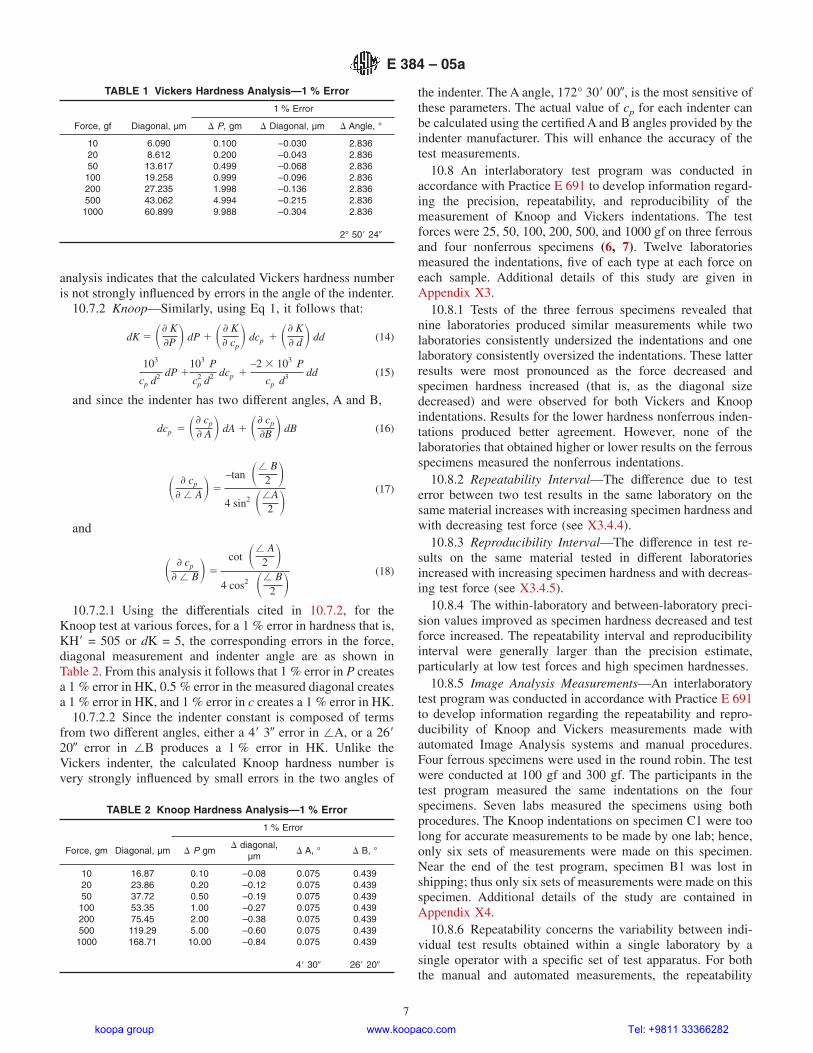
8.13.1 For most testing purposes, the minimum recom-mended spacing between separate tests, and minimum distancebetween an indentation and the surface of the specimen areillustrated in Fig. 3.
8.13.2 For some applications, closer spacing of indentationsthan those shown in Fig. 3 may be desired. If closer indentation
FIG. 3 Minimum Recommended Spacing for Knoop and Vickers Indentations
E 384 – 05a
5koopa group www.koopaco.com Tel: +9811 33366282
spacings are used, it shall be the responsibility of the testinglaboratory to verify the accuracy of the testing procedure.
9. Report
9.1 Report the following information:9.1.1 The test results, the number of tests, and, where
appropriate, the mean and standard deviation of the tests,9.1.2 Test force, and9.1.3 Any unusual conditions encountered during the test.9.2 The symbols HK for Knoop hardness, and HV for
Vickers hardness shall be used with the reported numericalvalues.
9.2.1 For this standard, the microindentation hardness testresults can be reported in several different ways. For example,if the Knoop hardness was found to be 400, and the test forcewas 100 gf, the test results may be reported as follows:.
9.2.1.1 In the Kilogram force system: 400 HK 0.1.9.2.1.2 In the gram force system: 400 HK 100 gf.9.2.1.3 In the SI system: 3.92 GPa.9.2.2 For nonstandard dwell times, other than 10 to 15 s, the
hardness would be reported as 400 HK 0.1 /22 s. In this case,22 s would be the actual time of full load dwell time.
10. Precision and Bias 3
10.1 The precision and bias of microindentation hardnessmeasurements depend on strict adherence to the stated testprocedure and are influenced by instrumental and materialfactors and indentation measurement errors.
10.2 The consistency of agreement for repeated tests on thesame material is dependent on the homogeneity of the material,reproducibility of the hardness tester, and consistent, carefulmeasurement of the indents by a competent operator.
10.3 Instrumental factors that can affect test results include:accuracy of loading; inertia effects; speed of loading; vibra-tions; the angle of indentation; lateral movement of theindenter or specimen; indentation and indenter shape devia-tions.
10.3.1 Vibrations during indenting will produce larger in-dentations with the influence of vibrations becoming larger asthe force decreases (1, 2).4
10.3.2 The angle between the indenter and specimen surfaceshould be within 2° of perpendicular. Greater amounts of tiltingproduce nonuniform indentations and invalid test results.
10.4 Material factors that can affect test results include:specimen homogeneity, orientation or texture effects; improperspecimen preparation; low specimen surface reflectivity; trans-parency of the specimen.
10.4.1 Residual deformation from mechanical polishingmust be removed, particularly for low-force testing.
10.4.2 Distortion of the indentation shape due to eithercrystallographic or microstructural texture influences diagonallengths and the validity of the calculated hardness.
10.4.3 Plastic deformation during indentation can produceridging around the indentation periphery that will affect diago-nal measurement accuracy.
10.4.4 Testing of etched surfaces, depending on the extentof etching, can produce results that are different from thoseobtained on unetched surfaces (1).
10.5 Measurement errors that can affect test results include:inaccurate calibration of the measuring device; inadequateresolving power of the objective; insufficient magnification;operator bias in sizing the indentations; poor image quality;nonuniform illumination, improper zeroing of the measuringdevice.
10.5.1 The accuracy of microindentation hardness testing isstrongly influenced by the accuracy to which the indentationscan be measured.
10.5.2 The error in measuring the diagonals increases as thenumerical aperture of the measuring objective decreases (3, 4).
10.5.3 Bias is introduced if the operator consistently under-sizes or oversizes the indentations.
10.6 Some of the factors that affect test results producesystematic errors that influence all test results while othersprimarily influence low-force test results (5). Some of theseproblems occur continually, others may occur in an undefined,sporadic manner. Low force hardness tests are influenced bythese factors to a greater extent than high force tests.
10.7 For both the Vickers and Knoop hardness tests, thecalculated microindentation hardness is a function of threevariables: force, indenter geometry and diagonal measurement.Total differentials of the equations used to calculate themicroindentation hardness can be used to evaluate the effectvariations in these parameters can cause.
10.7.1 Vickers—using Eq 6, the total differential for theVickers hardness number is:
dV 5 S] V] PD dP 1 S] V
]d D dd 1 S] V] aD da (10)
and
S] V] PD 5 2 3 103 3 d–2 3 sin Sa
2D (11)
S] V] dD 5 –4 3 103 3 P 3 d–3 sin Sa
2D (12)
S] V] aD 5 103 3 P 3 d–2 cos Sa
2D (13)
Thus, for a material having a hardness of 500 HV whentested with a 500 gf force, d = 43.06 µm, a = 136°, and
sin Sa
2D = 0.927184.
10.7.1.1 Consider introducing a 1 % error into the hardnessof the material through an error in either the applied force, theindenter constant or the measured diagonal length. In this case,the hardness would be HV8 = 505 or dV = 5. Using Eq 11-13,the corresponding errors in the various parameters are asshown in Table 1. Thus a 1 % change in P or a 2.09 % error ina creates a 1 % error in the Vickers hardness number. How-ever, only a 0.5 % error in the measured diagonal is needed tocreate a 1 % error in Vickers hardness. Furthermore, this
3 Supporting data have been filed at ASTM Headquarters. Request RR:E-04-1004.
4 The boldface numbers in parentheses refer to the list of references at the end ofthis standard.
E 384 – 05a
6
koopa group www.koopaco.com Tel: +9811 33366282
analysis indicates that the calculated Vickers hardness numberis not strongly influenced by errors in the angle of the indenter.
10.7.2 Knoop—Similarly, using Eq 1, it follows that:
dK 5 S] K]P D dP 1 S] K
] cpD dcp 1 S] K
] dD dd (14)
103
cp d2 dP 1103 P
cp2 d2 dcp 1
–2 3 103 P
cp d3 dd (15)
and since the indenter has two different angles, A and B,
dcp 5 S] cp
] AD dA 1 S] cp
]B D dB (16)
S ] cp
] / AD 5
–tan S/ B2 D
4 sin2 S/A2 D (17)
and
S ] cp
] / BD 5
cot S/ A2 D
4 cos2 S/ B2 D (18)
10.7.2.1 Using the differentials cited in 10.7.2, for theKnoop test at various forces, for a 1 % error in hardness that is,KH8 = 505 or dK = 5, the corresponding errors in the force,diagonal measurement and indenter angle are as shown inTable 2. From this analysis it follows that 1 % error in P createsa 1 % error in HK, 0.5 % error in the measured diagonal createsa 1 % error in HK, and 1 % error in c creates a 1 % error in HK.
10.7.2.2 Since the indenter constant is composed of termsfrom two different angles, either a 48 39 error in /A, or a 268
209 error in /B produces a 1 % error in HK. Unlike theVickers indenter, the calculated Knoop hardness number isvery strongly influenced by small errors in the two angles of
the indenter. The A angle, 172° 308 009, is the most sensitive ofthese parameters. The actual value of cp for each indenter canbe calculated using the certified A and B angles provided by theindenter manufacturer. This will enhance the accuracy of thetest measurements.
10.8 An interlaboratory test program was conducted inaccordance with Practice E 691 to develop information regard-ing the precision, repeatability, and reproducibility of themeasurement of Knoop and Vickers indentations. The testforces were 25, 50, 100, 200, 500, and 1000 gf on three ferrousand four nonferrous specimens (6, 7). Twelve laboratoriesmeasured the indentations, five of each type at each force oneach sample. Additional details of this study are given inAppendix X3.
10.8.1 Tests of the three ferrous specimens revealed thatnine laboratories produced similar measurements while twolaboratories consistently undersized the indentations and onelaboratory consistently oversized the indentations. These latterresults were most pronounced as the force decreased andspecimen hardness increased (that is, as the diagonal sizedecreased) and were observed for both Vickers and Knoopindentations. Results for the lower hardness nonferrous inden-tations produced better agreement. However, none of thelaboratories that obtained higher or lower results on the ferrousspecimens measured the nonferrous indentations.
10.8.2 Repeatability Interval—The difference due to testerror between two test results in the same laboratory on thesame material increases with increasing specimen hardness andwith decreasing test force (see X3.4.4).
10.8.3 Reproducibility Interval—The difference in test re-sults on the same material tested in different laboratoriesincreased with increasing specimen hardness and with decreas-ing test force (see X3.4.5).
10.8.4 The within-laboratory and between-laboratory preci-sion values improved as specimen hardness decreased and testforce increased. The repeatability interval and reproducibilityinterval were generally larger than the precision estimate,particularly at low test forces and high specimen hardnesses.
10.8.5 Image Analysis Measurements—An interlaboratorytest program was conducted in accordance with Practice E 691to develop information regarding the repeatability and repro-ducibility of Knoop and Vickers measurements made withautomated Image Analysis systems and manual procedures.Four ferrous specimens were used in the round robin. The testwere conducted at 100 gf and 300 gf. The participants in thetest program measured the same indentations on the fourspecimens. Seven labs measured the specimens using bothprocedures. The Knoop indentations on specimen C1 were toolong for accurate measurements to be made by one lab; hence,only six sets of measurements were made on this specimen.Near the end of the test program, specimen B1 was lost inshipping; thus only six sets of measurements were made on thisspecimen. Additional details of the study are contained inAppendix X4.
10.8.6 Repeatability concerns the variability between indi-vidual test results obtained within a single laboratory by asingle operator with a specific set of test apparatus. For boththe manual and automated measurements, the repeatability
TABLE 1 Vickers Hardness Analysis—1 % Error
1 % Error
Force, gf Diagonal, µm D P, gm D Diagonal, µm D Angle, °
10 6.090 0.100 –0.030 2.83620 8.612 0.200 –0.043 2.83650 13.617 0.499 –0.068 2.836100 19.258 0.999 –0.096 2.836200 27.235 1.998 –0.136 2.836500 43.062 4.994 –0.215 2.8361000 60.899 9.988 –0.304 2.836
2° 508 249
TABLE 2 Knoop Hardness Analysis—1 % Error
1 % Error
Force, gm Diagonal, µm D P gmD diagonal,
µmD A, ° D B, °
10 16.87 0.10 –0.08 0.075 0.43920 23.86 0.20 –0.12 0.075 0.43950 37.72 0.50 –0.19 0.075 0.439100 53.35 1.00 –0.27 0.075 0.439200 75.45 2.00 –0.38 0.075 0.439500 119.29 5.00 –0.60 0.075 0.4391000 168.71 10.00 –0.84 0.075 0.439
48 309 268 209
E 384 – 05a
7
koopa group www.koopaco.com Tel: +9811 33366282
interval increased with specimen hardness and decreasing testforce, Appendix X4. For equivalent testing conditions, therepeatability interval for automated measurements was slightlylarger than for manual measurements.
10.8.7 Reproducibility deals with the variability betweensingle test results obtained by different laboratories applyingthe same test methods to the same or similar test specimens.For both the manual and automated measurements, the repro-ducibility interval increased with specimen hardness and de-creasing test force, Appendix X4. For equivalent testingconditions, the reproducibility interval for automated measure-ments was slightly larger than for manual measurements.
10.8.8 Practice E 691 nor any other ASTM standard dealswith comparing test results of a single property made by twodifferent test methods. Hence it is not possible to statisticallyand accurately compare the hardness measurements made bythe manual and automated procedures. However, this informa-tion is graphically represented for comparative purposes, X4.6.
11. Conversion to Other Hardness Scales or TensileStrength Values
11.1 There is no generally accepted method for accurateconversion of Knoop or Vickers microindentation hardnessnumbers to other hardness scales or tensile strength values.Such conversions are limited in scope and should be used withcaution, except for special cases where a reliable basis for theconversion has been obtained by comparison tests. For loads$ 100 gf microindentation Vickers hardness numbers are inreasonable agreement with macro Vickers hardness numbers.Refer to Test Method E 140 for hardness conversion tables formetals.
12. Keywords
12.1 hardness; indentation; Knoop; microindentation;Vickers
ANNEXES
(Mandatory Information)
A1. VERIFICATION OF KNOOP AND VICKERS HARDNESS TESTING MACHINES AND INDENTERS
A1.1 Scope
A1.1.1 Annex A1 specifies three types of procedures forverifying microindentation (Knoop and Vickers) hardness test-ing machines: direct verification, indirect verification, andweekly verification. This annex also contains geometric speci-fications for the indenter.
A1.1.2 Direct verification is a process for verifying thatcritical components of the hardness testing machine are withinallowable tolerances by directly measuring the test forces,indentation measuring system, and testing cycle.
A1.1.3 Indirect verification is a process for periodicallyverifying the performance of the testing machine by means ofstandardized test blocks.
A1.1.4 The weekly verification is a process for monitoringthe performance of the testing machine between indirectverifications by means of standardized test blocks.
A1.2 General Requirements
A1.2.1 The testing machine shall be verified at specificinstances and at periodic intervals as specified in Table A1.1,and when circumstances occur that may affect the performanceof the testing machine.
A1.2.2 All instruments used to make measurements re-quired by this Annex shall be calibrated traceable to nationalstandards when a system of traceability exists, except as notedotherwise.
A1.2.3 Indirect verification of the testing machine shall beperformed at the location where it will be used.
A1.2.4 Direct verification of newly manufactured or rebuilttesting machines may be performed at the place of manufac-ture, rebuild or the location of use.
NOTE A1.1—It is recommended that the calibration agency that is usedto conduct the verifications of microindentation hardness testing machinesbe accredited to the requirements of ISO 17025 (or an equivalent) by arecognized accrediting body that operates to the requirements of ISOGuide 58.
A1.3 Direct Verification
A1.3.1 A direct verification of the testing machine shall beperformed at specific instances in accordance with Table A1.1.The test forces, indentation measuring system and testing cycleshall be verified as follows.
NOTE A1.2—Direct verification is a useful tool for determining thesources of error in a microindentation hardness testing machine. It isrecommended that testing machines undergo direct verification periodi-cally to make certain that errors in one component of the machine are not
TABLE A1.1 Verification Schedule for a MicroindentationHardness Testing Machine
VerificationProcedure
Schedule
Direct Verification When a testing machine is new, or when adjustments,modifications or repairs are made that could affect theapplication of the test forces or the measuring system.Follow the manufacturers recommendations todetermine when a direct verification is needed n arepaired, modified or adjusted instrument.When a testing machine fails an indirect verification.
Indirect Verification Shall be no longer than every 18 months.Recommended every 12 months.Recommended when a test machine is installed ormoved.
Weekly Verification Required each week that the machine is used.Recommended whenever the indenter or test force ischanged.
E 384 – 05a
8
koopa group www.koopaco.com Tel: +9811 33366282

being offset by errors in another component.
A1.3.2 Verification of the Test Forces—For each microin-dentation hardness scale that will be used, the correspondingtest force shall be measured. The test forces shall be measuredin accordance with ASTM E 4 by means of a Class A elasticforce measuring instrument having an accuracy of at least0.25 %, as described in ASTM E 74.
A1.3.2.1 Make three measurements of each force. Theforces shall be measured as they are applied during testing;however, longer dwell times are allowed when necessary toenable the measuring device to obtain accurate measurements.
A1.3.2.2 Each test force F shall meet the requirementsspecified in Table A1.2.
A1.3.3 Verification of the Indentation Measuring System—The measuring device used to determine the diagonal of theindentation shall be verified at five evenly spaced intervals overthe working range by comparison with an accurate scale suchas a stage micrometer. The line interval accuracy of the stagemicrometer shall be 0.1 micron or 0.05 %, which ever isgreater. Throughout the range covered, the difference betweenthe reading of the device and of the stage micrometer shall notexceed 0.4 microns or 0.5 %, which ever is greater.
A1.3.4 Verification of the Testing Cycle—The testing ma-chine shall be verified to be capable of meeting the testingcycle tolerances specified in 6.1. Direct verification of thetesting cycle is to be verified by the testing machine manufac-turer at the time of manufacture, or when the testing machineis returned to the manufacturer for repair, or when a problemwith the testing cycle is suspected. Verification of the testingcycle is recommended but not required as part of the directverification at other times.
NOTE A1.3—Instruments that have timing controlled by software orother nonadjustable components do not have to be verified providing thatthe design has been proven to produce the correct time cycles.
A1.3.5 Verification of Indenter—The geometry of the in-denter is verified at time of manufacturing and it is mandatoryfor new machines. Subsequent verifications of the indenter areperformed by visual inspection of the resulting indentation; itis sufficient to verify the absence of defects from the shape ofindentations performed on test blocks. The indenter Geometryis specified as follows:
A1.3.5.1 Vickers Microindentation Indenter:(1) The Vickers microindentation indenter for standard use,
direct verification, and indirect verification shall have faceangles of 136° 08 6 308.
(2) The offset shall not exceed 0.5 µm.(3) The four faces of the diamond shall be equally inclined
to the axis of the indenter to within 6 308, as shown in Fig. 2.Vickers microindentation diamond indenters used for calibrat-ing test blocks shall have face angles of 136° 08 6 68.
NOTE A1.4—It is permissible to verify the offset by using a microscopewith at least 5003 magnification to view an indent created by the indenter
and compare the offset length to a known dimension.
A1.3.5.2 Knoop Indenter:(1) The ideal Knoop diamond indenter has an included
longitudinal edge angle, / A = 172° 308, and includedtransverse edge angle, / B = 130° 08. The ideal indenterconstant, cp = 0.07028. For all indenters, cp shall be within 6
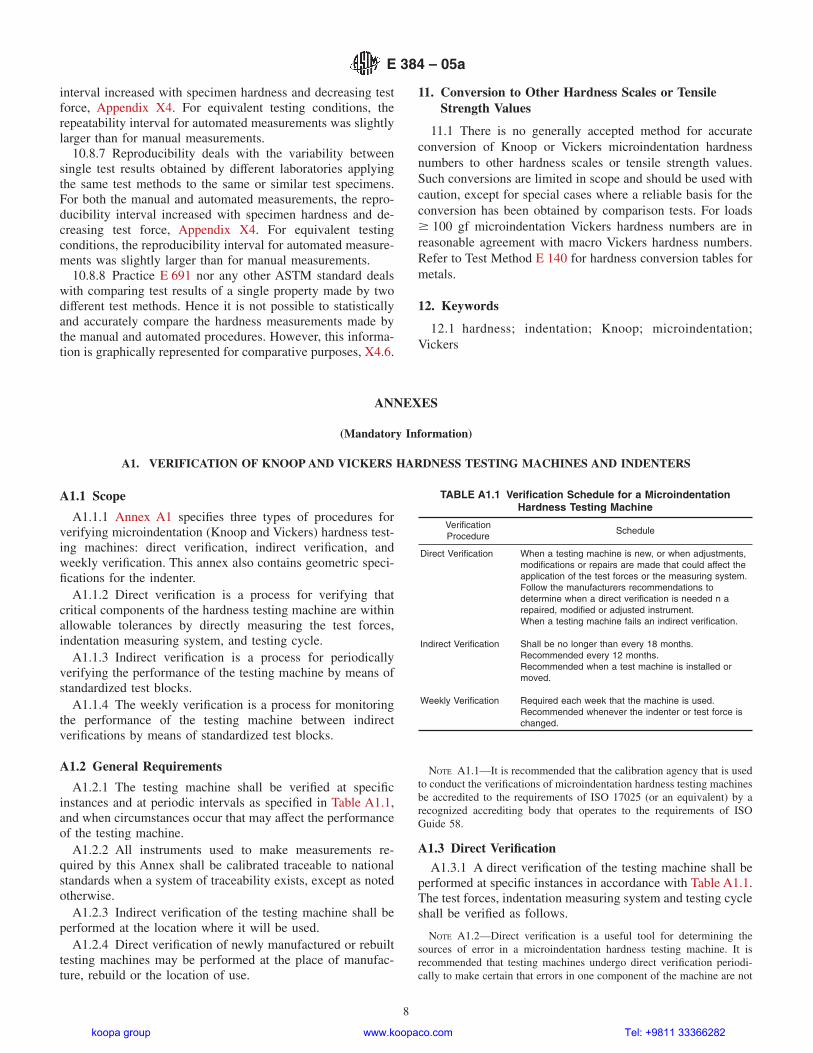
1 % of the ideal value, 0.06958 # cp # 0.07098.(2) The tolerance of / A = 172° 308, shall be 6 0.10° 68.(3) The corresponding / B = 130° must be contained
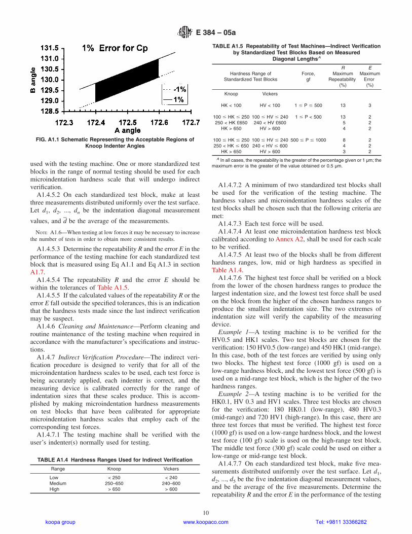
within the dimensions listed in Table A1.3 and graphically asdescribed by Fig. A1.1.
(4) The offset shall not be more than 1 µm in length forindentations greater than 15 µm in length, as shown in Fig. 1.For shorter indentations the offset should be proportionallyless.
(5) The four faces of the diamond shall be equally inclinedto the axis of the indenter to within 6 308, as shown in Fig. 1.
(6) The device used to verify the indenter shall have a max.uncertainty of 6 40 minutes.
A1.3.6 Direct Verification Failure—If any of the directverifications fail the specified requirements, the testing ma-chine shall not be used until it is adjusted or repaired. If the testforces, indentation measuring system or testing cycle may havebeen affected by an adjustment or repair, the affected compo-nents shall be verified again by a direct verification.
A1.4 Indirect Verification
A1.4.1 An indirect verification of the testing machine shallbe performed in accordance with the schedule given in TableA1.1. Indirect verifications may be required more frequentlythan stated in Table A1.1 and should be based on the usage ofthe testing machine.
A1.4.2 The testing machine shall be verified for each testforce and for each indenter that will be used prior to the nextindirect verification. Hardness tests made using microindenta-tion hardness scales that have not been verified within theschedule given in Table A1.1 do not meet this standard.
A1.4.3 Standardized test blocks used for the indirect veri-fication shall meet the requirements of Annex A2.
NOTE A1.5—It is recognized that appropriate standardized test blocksare not available for all geometric shapes, materials, or hardness ranges.
A1.4.4 The indenter(s) to be used for the indirect verifica-tion shall meet the requirements of A1.3.5.
A1.4.5 As-found Condition—It is recommended that theas-found condition of the testing machine be assessed as part ofan indirect verification. This is important for documenting thehistorical performance of the machine. This procedure shouldbe conducted by the verification agency prior to any cleaning,maintenance, adjustments, or repairs.
A1.4.5.1 The as-found condition of the testing machineshall be determined with the user’s indenter that is normally
TABLE A1.2 Accuracy of Applied Forces
Applied Force, gf Accuracy, %P < 200 1.5P $ 200 1.0
TABLE A1.3 Angular Tolerances for Knoop Indenters
A Angle, °B Angle, °
Minimum Maximum
172.4 128.97 129.85172.6 130.15 131.02
E 384 – 05a
9
koopa group www.koopaco.com Tel: +9811 33366282
used with the testing machine. One or more standardized testblocks in the range of normal testing should be used for eachmicroindentation hardness scale that will undergo indirectverification.
A1.4.5.2 On each standardized test block, make at leastthree measurements distributed uniformly over the test surface.Let d1, d2, ..., dn be the indentation diagonal measurement
values, and d–
be the average of the measurements.
NOTE A1.6—When testing at low forces it may be necessary to increasethe number of tests in order to obtain more consistent results.
A1.4.5.3 Determine the repeatability R and the error E in theperformance of the testing machine for each standardized testblock that is measured using Eq A1.1 and Eq A1.3 in sectionA1.7.
A1.4.5.4 The repeatability R and the error E should bewithin the tolerances of Table A1.5.
A1.4.5.5 If the calculated values of the repeatability R or theerror E fall outside the specified tolerances, this is an indicationthat the hardness tests made since the last indirect verificationmay be suspect.
A1.4.6 Cleaning and Maintenance—Perform cleaning androutine maintenance of the testing machine when required inaccordance with the manufacturer’s specifications and instruc-tions.
A1.4.7 Indirect Verification Procedure—The indirect veri-fication procedure is designed to verify that for all of themicroindentation hardness scales to be used, each test force isbeing accurately applied, each indenter is correct, and themeasuring device is calibrated correctly for the range ofindentation sizes that these scales produce. This is accom-plished by making microindentation hardness measurementson test blocks that have been calibrated for appropriatemicroindentation hardness scales that employ each of thecorresponding test forces.
A1.4.7.1 The testing machine shall be verified with theuser’s indenter(s) normally used for testing.
A1.4.7.2 A minimum of two standardized test blocks shallbe used for the verification of the testing machine. Thehardness values and microindentation hardness scales of thetest blocks shall be chosen such that the following criteria aremet:
A1.4.7.3 Each test force will be used.A1.4.7.4 At least one microindentation hardness test block
calibrated according to Annex A2, shall be used for each scaleto be verified.
A1.4.7.5 At least two of the blocks shall be from differenthardness ranges, low, mid or high hardness as specified inTable A1.4.
A1.4.7.6 The highest test force shall be verified on a blockfrom the lower of the chosen hardness ranges to produce thelargest indentation size, and the lowest test force shall be usedon the block from the higher of the chosen hardness ranges toproduce the smallest indentation size. The two extremes ofindentation size will verify the capability of the measuringdevice.
Example 1—A testing machine is to be verified for theHV0.5 and HK1 scales. Two test blocks are chosen for theverification: 150 HV0.5 (low-range) and 450 HK1 (mid-range).In this case, both of the test forces are verified by using onlytwo blocks. The highest test force (1000 gf) is used on alow-range hardness block, and the lowest test force (500 gf) isused on a mid-range test block, which is the higher of the twohardness ranges.
Example 2—A testing machine is to be verified for theHK0.1, HV 0.3 and HV1 scales. Three test blocks are chosenfor the verification: 180 HK0.1 (low-range), 480 HV0.3(mid-range) and 720 HV1 (high-range). In this case, there arethree test forces that must be verified. The highest test force(1000 gf) is used on a low-range hardness block, and the lowesttest force (100 gf) scale is used on the high-range test block.The middle test force (300 gf) scale could be used on either alow-range or mid-range test block.
A1.4.7.7 On each standardized test block, make five mea-surements distributed uniformly over the test surface. Let d1,d2, ..., d5 be the five indentation diagonal measurement values,and be the average of the five measurements. Determine therepeatability R and the error E in the performance of the testing
FIG. A1.1 Schematic Representing the Acceptable Regions ofKnoop Indenter Angles
TABLE A1.4 Hardness Ranges Used for Indirect Verification
Range Knoop Vickers
Low < 250 < 240Medium 250–650 240–600High > 650 > 600
TABLE A1.5 Repeatability of Test Machines—Indirect Verificationby Standardized Test Blocks Based on Measured
Diagonal LengthsA
Hardness Range ofStandardized Test Blocks
Force,gf
RMaximum
Repeatability(%)
EMaximum
Error(%)
Knoop Vickers
HK < 100 HV < 100 1 # P # 500 13 3
100 # HK # 250 100 # HV # 240 1 # P < 500 13 2250 < HK £650 240 < HV £600 5 2
HK > 650 HV > 600 4 2
100 # HK # 250 100 # HV # 240 500 # P # 1000 8 2250 < HK # 650 240 < HV # 600 4 2
HK > 650 HV > 600 3 2A In all cases, the repeatability is the greater of the percentage given or 1 µm; the
maximum error is the greater of the value obtained or 0.5 µm.
E 384 – 05a
10
koopa group www.koopaco.com Tel: +9811 33366282

machine using Eq A1.1 and Eq A1.3 in section A1.7, for eachhardness level of each microindentation hardness scale to beverified. The repeatability R and the error E shall be within thetolerances of Table A1.5.
A1.4.7.8 If the measurements of error E or repeatability Rusing the user’s indenter fall outside of the specified tolerances,the indirect verification measurements may be repeated using adifferent indenter.
A1.4.7.9 The indirect verification shall be approved onlywhen the testing machine measurements of repeatability anderror meet the specified tolerances with the user’s indenter.
A1.4.8 In cases where it is necessary to replace the indenterduring the period between indirect verifications, the newindenter must be verified for use with the specific testingmachine. The user shall perform the verification by followingthe as-found procedures given in A1.4.5. If the repeatability, R,and error, E, values fall within the tolerances in Table A1.5 theindenter can be used.
A1.4.9 When the combination of block hardness and testforce produces indentations with diagonals less than 20 µmlong, indirect verification using standardized test blocks is notrecommended. In these situations, the indentation measure-ment error represents a significant proportion of the diagonallength. This can lead to substantial deviations in hardness fromthe stated value. Examples of these errors are contained inSection 10 and Tables 1 and 2.
A1.5 Weekly Verification
A1.5.1 The weekly verification is intended as a tool for theuser to monitor the performance of the testing machinebetween indirect verifications. At a minimum, the weeklyverification shall be performed in accordance with the schedulegiven in Table A1.1 for each microindentation hardness scalethat will be used. It is strongly recommended that thisverification should be performed on a daily basis.
A1.5.2 It is recommended that the weekly verificationprocedures be performed whenever the indenter or test force ischanged.
A1.5.3 Weelky Verification Procedures—The procedures touse when performing a weekly verification are as follows.
A1.5.3.1 At least one standardized test block that meets therequirements of Annex A2 shall be used for each microinden-tation hardness scale to be used. When test blocks are com-mercially available, the hardness level of the test blocks shallbe chosen at approximately the same hardness value as thematerial to be measured.
A1.5.3.2 The indenter to be used for the weekly verificationshall be the indenter that is normally used for testing.
A1.5.3.3 Before performing the weekly verification tests,ensure that the testing machine is working freely, the stage andtest block are clean, and the measuring device is properlyadjusted and zeroed.
A1.5.3.4 Make at least three hardness measurements oneach of the verification test blocks. The tests shall be distrib-uted uniformly over the surface of the test blocks.
A1.5.3.5 Let d–
be the average of the measurements. Deter-mine the error E in the performance of the testing machineusing Eq A1.3 for each standardized test block that is mea-sured.
A1.5.3.6 If the error E calculated for each test block iswithin the tolerances given in Table A1.5, the testing machinewith the indenter may be regarded as performing satisfactorily.
A1.5.3.7 If the error E calculated for any of the test blocksis outside the tolerances, the weekly verification may berepeated with a different indenter. If the average of thehardness measurements again falls outside of tolerances forany of the test blocks, an indirect verification shall be per-formed.
A1.5.3.8 Whenever a testing machine fails a weekly verifi-cation, the hardness tests made since the last valid weeklyverification may be suspect.
NOTE A1.7—It is highly recommended that the results obtained fromthe weekly verification testing be recorded using accepted StatisticalProcess Control techniques, such as, but not limited to, X-bar (measure-ment averages) and R-charts (measurement ranges), and histograms.
A1.6 Verification Report
A1.6.1 A verification report is required for direct andindirect verifications. A verification report is not required for aweekly verification.
A1.6.2 The verification report shall be produced by theperson performing the verification and include the followinginformation when available as a result of the verificationperformed.
A1.6.2.1 Reference to this ASTM test method.A1.6.2.2 Method of verification.A1.6.2.3 Identification of the hardness testing machine and
the indenters used.A1.6.2.4 Means of verification (test blocks, elastic proving
devices,etc.) with statements defining traceability to a nationalstandard.
A1.6.2.5 The microindentation hardness scale(s) verified.A1.6.2.6 The individual or calculated results used to deter-
mine whether the testing machine meets the requirements ofthe verification performed. Measurements made to determinethe as-found condition of the testing machine shall be includedwhenever they are made.
A1.6.2.7 Description of adjustments or maintenance done tothe testing machine.
A1.6.2.8 Date of verification and reference to the verifyingagency or department.
A1.6.2.9 Signature of the person performing the verifica-tion.
A1.7 Example Calculations of Repeatability and Error
A1.7.1 Repeatability of Microindentation Hardness Tester:A1.7.1.1 Repeatability, R, of the tester (%) is calculated by
the following equation:
R 5 100 Sdmax – dmin
d– D (A1.1)
where dmax is the longest of the five diagonals (or mean
diagonals), dmin is the shortest of the five diagonals, and d–
is the
E 384 – 05a
11
koopa group www.koopaco.com Tel: +9811 33366282

mean diagonal length. The repeatability is acceptable if itmeets the requirements given in Table A1.5.
A1.7.1.2 The following is an example of a reapeatabilitycalculation. Assume that five Knoop indentations were madeon a test block with a nominal hardness of 404 HK at thecertified block test force of 300 gf and that the five readings ared1 = 103.9, d2 = 104.8, d3 = 102.3, d4 = 102.8 and d5 = 100.2µm, respectively. Therefore, dmax – dmin = 104.8 – 100.2 = 4.6µm and R = 100(4.6)/102.8 = 4.47 %. According to Table A1.3,the repeatability for a test block with a hardness >250 to 650HK should be <5 %. In this example, the tester met therepeatability requirement for this hardness test block and force.However, if these diagonals had been obtained using a testblock with a nominal hardness of 700 HK and a certified testforce of 500 gf, then the repeatability would be inadequate asTable A1.3 requires R <4 % for a hardness >650 HK.
A1.7.2 Error of Microindentation Hardness Tester:A1.7.2.1 The error, E, of the machine is:
E 5 d–– ds (A1.2)
The percent error, %E, is calculated by the followingequation:
%E 5 100 Sd–
– ds
dsD (A1.3)
where d–
is the measured mean diagonal length and ds is thereported certified mean diagonal length, µm.
A1.7.2.2 The error between the certified mean diagonal andthe measured mean diagonal shall not exceed the tolerances inTable A1.5, or 6 0.5 µm, whichever is greater.
A1.7.2.3 The following is an example of an error calcula-tion based on the data given in A1.4.5.2, and a certified meandiagonal length for the test block, ds, of 100.8 µm (420
HK300gf). Since d–
= 102.8 µm, ( d–
– ds) = 102.8 – 100.8 = 2.0µm. Thus, E = 1.98 %. In this case, the percent error meets themaximum of 6 2 %, which is greater than 6 0.5 µm. For this
example, d–
– ds must be > 6 2.016 µm for the error to be abovethe limit of 6 2 %.
A2. CALIBRATION OF STANDARDIZED HARDNESS TEST BLOCKS FOR MICROINDENTATIONHARDNESS TEST MACHINES
A2.1 Scope
A2.1.1 This annex describes the calibration of standardizedhardness test blocks used to verify microindentation hardnesstest machines. The standardizing machine shall meet the directverification method described in A1.3.
A2.2 Test Block Manufacture
A2.2.1 The test block thickness shall be greater than twentytimes the depth of the indentation made with the certified testforce.
A2.2.2 The test block material and manufacturing processesshall be chosen to produce the required degree of homogeneity,structural stability and uniformity of hardness at the preparedsurface.
A2.2.3 Ferromagnetic test blocks shall be demagnetized bythe manufacturer and shall be maintained in that condition bythe user.
A2.2.4 The test block support surface shall have a finelyground surface finish. The maximum deviation from flatness ofthe test and support surfaces shall not exceed 5 µm. Themaximum error in parallelism shall not exceed 15 µm in 30mm.
A2.2.5 The test block test surface shall be polished accord-ing to the procedures in Methods E 3 to yield the truemicrostructure, free from scratches that would interfere withproduction of the impression or measurement of the impressiondiagonal(s). The mean, centerline average, surface roughnessheight measurement of the test surface shall not exceed 0.1 µm(4 µin.).
A2.2.6 Repolishing of the test block will invalidate thestandardization and is not recommended. Cleaning of thepolished test block surface is often required in normal usagebut must not alter the hardness or quality of the polished testsurface.
A2.3 Standardizing Tester Requirements
A2.3.1 The standardizing tester shall comply with AnnexA1 with the following additional requirements:
A2.3.2 Direct verifications shall be performed every 12months.
A2.3.3 The Vickers indenter shall have the following anglesand tolerances (see Fig. 2).
A2.3.3.1 The face angles shall be 136° 0 6 68.A2.3.3.2 The face angles shall be equally inclined to the
axis of the indenter within 6 158.A2.3.3.3 The offset should not exceed 0.3 µm, see Note
A1.4.A2.3.4 The Knoop indenter shall have an indenter constant
of 0.07028 6 0.5 %. The offset should not exceed 0.5 µm, seeNote A1.4.
A2.3.5 The test force application time shall be between 5and 7 seconds. The test force dwell time shall be between 13and 15 seconds.
A2.3.6 The indent measuring system shall be verified ac-cording to A1.3.3. The difference between the reading deviceand the stage micrometer shall not exceed 0.2 µ or 0.25 %,which ever is greater.
E 384 – 05a
12
koopa group www.koopaco.com Tel: +9811 33366282

A2.3.7 Indirect verifications shall be performed using NISTSRM test blocks whenever they are available.
A2.4 Test Block Standardization Procedure
A2.4.1 Certification of the hardness test blocks shall beperformed with a microindentation hardness test machine thathas been verified by the direct method. Direct verification ofthis machine must be performed at least once every 12 months,as described in A1.3.5.
A2.4.2 Test Cycle:A2.4.2.1 The time from the first contact between the in-
denter and the test specimen until the full test force is appliedshall be within 5 and 7 s.
A2.4.2.2 The full test force shall be applied from 13 to 15 s.A2.4.3 Make five groups of impressions, each containing
five impressions, where one group is in the center of each ofthe four quadrants of the block and the fifth group is in thecenter of the test block.
A2.4.4 Adjust the illumination for the measuring system toproduce uniform intensity over the field of view and optimumcontrast between the impressions and the block surface (see6.4.1, 6.4.2, and Appendix X1).
A2.4.5 Measure the Knoop diagonal length, or averageVickers diagonal length of each of the twenty-five impressions.Record the data by group and by block. It is recommended thateach indentation be measured by two observers (compare testresults by rater).
A2.5 Repeatability of the Standardized Test Block
A2.5.1 Calculate the mean and standard deviation of thediagonals, or average diagonals, for the five indentations ineach of the five groups.
A2.5.2 The repeatability, R, of the impression size and,therefore, of the hardness, is calculated in the manner describedin A1.4.5.5 by Eq A1.1. Calculate the mean of all 25 measured
diagonals, or average diagonals, d–, and determine dmax and
dmin, the longest and shortest of the 25 measurements, respec-tively. R is a measure of the hardness homogeneity of the testblock, although R is influenced by all of the variables thataffect the repeatability of microindentation test results.
A2.5.3 Table A2.1 lists the required maximum R values fortest blocks by indenter type, test force range and hardnessrange. The measured R value must be less than these limits forit to be considered sufficiently uniform enough in hardness tofunction as a standardized test block.
A2.6 Marking
A2.6.1 The test surface of each block shall be permanentlymarked with the thickness of the block, an appropriate identi-fying serial number, the name or mark of the supplier or anidentification mark.
A2.6.2 When the test blocks are encapsulated in a mountingmedium, the information contained in A2.6.1 shall be perma-nently placed on the surface of the medium that contains thetest surface. The reported thickness shall be the thickness of themounting medium, not the thickness of the encapsulated block.
A2.7 Certification of Standardized Test Block
A2.7.1 The certificate accompanying each standardizedhardness test block shall include the following information:The arithmetic mean of each group of five impression diago-nals; the arithmetic mean and standard deviation of all twenty-five impression diagonals, the corresponding hardness value,the test force, serial number of the test block, name of themanufacturer and certifying organization, magnification used,and the date.
APPENDIXES
(Nonmandatory Information)
X1. ADJUSTMENT OF KÖHLER ILLUMINATION SYSTEMS
X1.1 While some optical systems are permanently aligned,others have means for minor adjustments. To gain the utmost inresolution, the operator should make the following adjust-ments:
X1.1.1 Focus the surface of a flat polished specimen tocritical sharpness.
X1.1.2 Center the illumination source.X1.1.3 Centrally align field and aperture diaphragms.X1.1.4 Open the field diaphragm so that it just disappears
from the field of view.X1.1.5 Remove the eyepiece and examine the rear focal
plane of the objective. If all the components are in their proper
TABLE A2.1 Repeatability of Diagonal Measurements forStandardized Test Block CertificationA
Hardness Range of Standardized Test Blocks Force, gfR, %, Less
Than
Knoop Vickers
100 # HK # 250 100 # HV # 240 1 # P < 500 12250 < HK # 650 240 < HV # 600 4
HK > 650 HV > 600 3
100 # HK # 250 100 # HV # 240 500 #P # 1000 7250 < HK # 650 240 < HV # 600 3
HK > 650 HV > 600 2A In all cases, the repeatability limit is the greater of the percentage given or 1
µm.
E 384 – 05a
13koopa group www.koopaco.com Tel: +9811 33366282

places, the source of illumination and the aperture diaphragmwill appear in sharp focus.
X1.1.6 Full-aperture diaphragm is preferred for maximumresolving power. If glare is excessive, reduce the aperture, butnever use less than the 3⁄4 opening since resolution would bedecreased and diffraction phenomena could lead to falsemeasurements.
X1.1.7 If the light is too strong for eye comfort, reduce theintensity by the use of an appropriate neutral density filter orrheostat control.
X2. CORRELATION OF MICROINDENTATION HARDNESS TEST DATA BETWEEN LABORATORIES
X2.1 Scope
X2.1.1 This procedure provides guidance in the comparisonof microindentation hardness test data from two or morelaboratories.
X2.2 Correlation Procedure
X2.2.1 All laboratories shall first establish that their testequipment conforms to the requirements in Test Method E 384.
X2.2.2 The specimens shall be taken from adjoining areasof the larger specimen prior to being sent to the cooperatinglaboratories for specimen preparation and testing.
X2.2.3 The specimens shall be prepared for microindenta-tion hardness by two or more laboratories using essentially thesame procedures. If the specimens are capable of beingprepared as metallographic specimens, established ASTMprocedures shall be maintained uniformly among the laborato-ries as follows:
X2.2.3.1 The same surfaces shall be exposed for the micro-indentation hardness test. This is to ensure that grain direction,if a characteristic, is taken into consideration.
X2.2.3.2 The surface preparation of the specimens shall bein accordance with Methods E 3.
X2.2.4 All laboratories shall calibrate the optics of their testapparatus using a stage micrometer in accordance with A1.3.3.
X2.2.5 The indentations shall be oriented the same wayrelative to grain direction in order to avoid differences inresults arising from this factor.
X2.2.6 The method of measuring the indentations shall beestablished prior to making the tests. It shall be the mostaccurate method as described by the equipment manufacturer.
X2.2.7 A minimum number of indentations shall be estab-lished. This shall conform to acceptable statistical methods ofanalysis, in accordance with Practice E 122.
X2.2.8 Each test specimen shall be indented and measuredby the laboratory having prepared it, then sent with the data fortesting in the other laboratory or laboratories.
X2.2.8.1 After the specimens have been exchanged, eachlaboratory shall measure and record the indentations applied bythe originating laboratory in a manner identical to the initialmeasurements.
X2.2.8.2 Each laboratory shall then repeat the indentationand measuring procedures, as performed in X2.2.5 and X2.2.6,before sending the data and specimen to the remaining labo-ratory or laboratories.
X2.2.8.3 Each laboratory shall determine a set of microin-dentation hardness values from the specimen they prepared, aswell as sets of values they obtained by indenting and measuringspecimens prepared by the other laboratory or laboratories.
X2.2.9 All data shall then be analyzed by the same accept-able statistical methods to establish the limits of agreement thatare attainable between the two laboratories. As a minimum, thefollowing statistical data shall be evolved:
X2.2.9.1 Mean, X,X2.2.9.2 Standard deviation, s, andX2.2.9.3 Standard error of the mean, s/X.
X2.3 Referee
X2.3.1 If the laboratories cannot establish an acceptablecorrelation through this procedure, it will be necessary tointroduce an independent laboratory to act as the referee.
X3. RESULTS OF INTERLABORATORY TEST OF THE MEASUREMENT OF MICROINDENTATIONS
X3.1 Introduction
X3.1.1 This interlaboratory test program was conducted todevelop precision and bias estimates for the measurement ofboth Knoop and Vickers indentations using forces of 25 to1000 gf for ferrous and nonferrous specimens covering a widerange of hardness.
X3.2 Scope
X3.2.1 This interlaboratory test program provides informa-tion on the measurement of the same indentations by differentlaboratories according to the procedures of Practice E 691.
X3.3 Procedure
X3.3.1 Five indentations were made under controlled con-ditions at each force (25, 50, 100, 200, 500, and 1000 gf), withboth Knoop and Vickers indenters using three ferrous and fournonferrous specimens.
X3.3.2 Twelve laboratories measured the indentations onthe ferrous specimens and the nonferrous specimens. Twolaboratories measured the hardnesses of both groups.
X3.3.3 Each laboratory used the same stage micrometer tocalibrate their measuring device.
E 384 – 05a
14
koopa group www.koopaco.com Tel: +9811 33366282
X3.3.4 Results were tabulated and analyzed in accordancewith Practice E 691.
X3.4 Results
X3.4.1 For the three ferrous specimens, results from ninelaboratories showed general agreement as to the diagonal sizes.Two other laboratories consistently undersized the indentations(higher hardness) and one laboratory consistently oversized theindentations (lower hardness). This bias was observed withboth Vickers and Knoop indentations sized by these laborato-ries with the degree of bias increasing as the indentation sizedecreased and the specimen hardness increased. Test on thefour nonferrous specimens produced general agreement, butnone of the three laboratories that produced biased results forthe ferrous specimens measured the nonferrous specimens.
X3.4.2 For the Vickers test data, the calculated hardnessincreased with increasing force and then became reasonablyconstant. This trend was apparent in the data from the nineconsistent laboratories (ferrous specimens) and for the labora-tory that oversized the indentations. The two laboratories thatconsistently undersized the Vickers indentations exhibitedsubstantial data scatter for the tests with forces of less than 100gf. However for higher forces, their indentation measurementswere relatively constant. The force at which the hardnessbecame relatively constant increased with increasing specimenhardness. For specimens below about 300 HV, there wasrelatively little difference in HV over the test force range.
X3.4.3 For the Knoop test data, most of the laboratoriesagreed that the hardness decreased continually with increasingtest force and then became reasonably constant. However, thetwo laboratories that exhibited outlier data for the ferrousspecimens did show the opposite trend; this is quite unusual.The difference in HK values between low forces and highforces increased with increasing specimen hardness. For speci-mens with hardnesses below about 300 HK, the difference inhardness was quite small over the test force range.
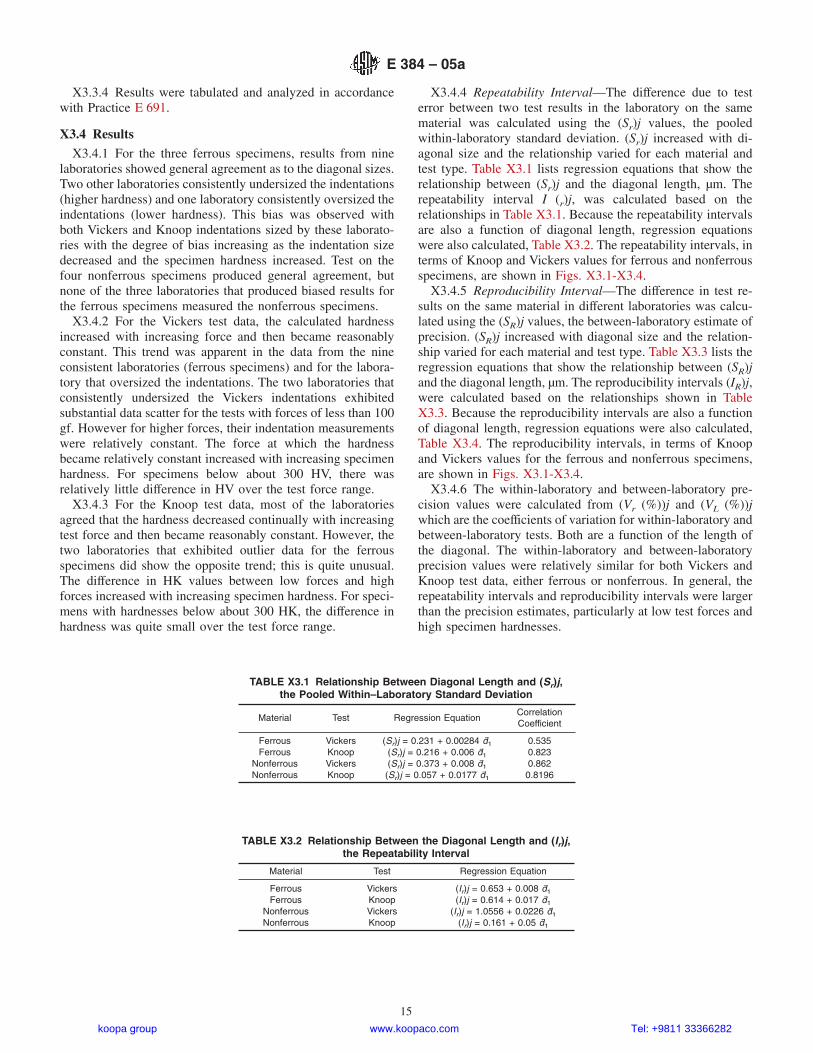
X3.4.4 Repeatability Interval—The difference due to testerror between two test results in the laboratory on the samematerial was calculated using the (Sr)j values, the pooledwithin-laboratory standard deviation. (Sr)j increased with di-agonal size and the relationship varied for each material andtest type. Table X3.1 lists regression equations that show therelationship between (Sr)j and the diagonal length, µm. Therepeatability interval I (r)j, was calculated based on therelationships in Table X3.1. Because the repeatability intervalsare also a function of diagonal length, regression equationswere also calculated, Table X3.2. The repeatability intervals, interms of Knoop and Vickers values for ferrous and nonferrousspecimens, are shown in Figs. X3.1-X3.4.
X3.4.5 Reproducibility Interval—The difference in test re-sults on the same material in different laboratories was calcu-lated using the (SR)j values, the between-laboratory estimate ofprecision. (SR)j increased with diagonal size and the relation-ship varied for each material and test type. Table X3.3 lists theregression equations that show the relationship between (SR)jand the diagonal length, µm. The reproducibility intervals (IR)j,were calculated based on the relationships shown in TableX3.3. Because the reproducibility intervals are also a functionof diagonal length, regression equations were also calculated,Table X3.4. The reproducibility intervals, in terms of Knoopand Vickers values for the ferrous and nonferrous specimens,are shown in Figs. X3.1-X3.4.
X3.4.6 The within-laboratory and between-laboratory pre-cision values were calculated from (Vr (%))j and (VL (%))jwhich are the coefficients of variation for within-laboratory andbetween-laboratory tests. Both are a function of the length ofthe diagonal. The within-laboratory and between-laboratoryprecision values were relatively similar for both Vickers andKnoop test data, either ferrous or nonferrous. In general, therepeatability intervals and reproducibility intervals were largerthan the precision estimates, particularly at low test forces andhigh specimen hardnesses.
TABLE X3.1 Relationship Between Diagonal Length and (Sr)j,the Pooled Within–Laboratory Standard Deviation
Material Test Regression EquationCorrelationCoefficient
Ferrous Vickers (Sr)j = 0.231 + 0.00284 d̄1 0.535Ferrous Knoop (Sr)j = 0.216 + 0.006 d̄1 0.823
Nonferrous Vickers (Sr)j = 0.373 + 0.008 d̄1 0.862Nonferrous Knoop (Sr)j = 0.057 + 0.0177 d̄1 0.8196
TABLE X3.2 Relationship Between the Diagonal Length and (Ir)j,the Repeatability Interval
Material Test Regression Equation
Ferrous Vickers (Ir)j = 0.653 + 0.008 d̄1
Ferrous Knoop (Ir)j = 0.614 + 0.017 d̄1
Nonferrous Vickers (Ir)j = 1.0556 + 0.0226 d̄1
Nonferrous Knoop (Ir)j = 0.161 + 0.05 d̄1
E 384 – 05a
15
koopa group www.koopaco.com Tel: +9811 33366282

TABLE X3.3 Relationship Between Diagonal Length and (SR)j,the Between-Laboratory Estimate of Precision
Material Test Regression EquationCorrelationCoefficient
Ferrous Vickers (SR)j = 0.31 + 0.004 d̄1 0.747Ferrous Knoop (SR)j = 0.333 + 0.007 d̄1 0.899
Nonferrous Vickers (SR)j = 0.357 + 0.0156 d̄1 0.8906Nonferrous Knoop (SR)j = 0.378 + 0.0177 d̄1 0.8616
TABLE X3.4 Relationship Between the Diagonal Length and (IR)j,the Repeatability Interval
Material Test Regression Equation
Ferrous Vickers (IR)j = 0.877 + 0.0113 d̄1
Ferrous Knoop (IR)j = 0.946 + 0.0198 d̄1
Nonferrous Vickers (IR)j = 1.0103 + 0.0441 d̄1
Nonferrous Knoop (IR)j = 1.07 + 0.05 d̄1
FIG. X3.1 Repeatability and Reproducibility Intervals in Terms of Vickers Hardness (6) for the Ferrous Samples as a Function ofTest Load and Specimen Hardness
FIG. X3.2 Repeatability and Reproducibility Intervals in Terms of Knoop Hardness (6) for the Ferrous Samples as a Function ofTest Load and Specimen Hardness
E 384 – 05a
16
koopa group www.koopaco.com Tel: +9811 33366282
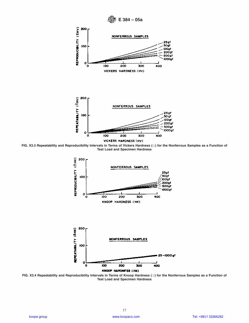
FIG. X3.3 Repeatability and Reproducibility Intervals in Terms of Vickers Hardness (6) for the Nonferrous Samples as a Function ofTest Load and Specimen Hardness
FIG. X3.4 Repeatability and Reproducibility Intervals in Terms of Knoop Hardness (6) for the Nonferrous Samples as a Function ofTest Load and Specimen Hardness
E 384 – 05a
17
koopa group www.koopaco.com Tel: +9811 33366282
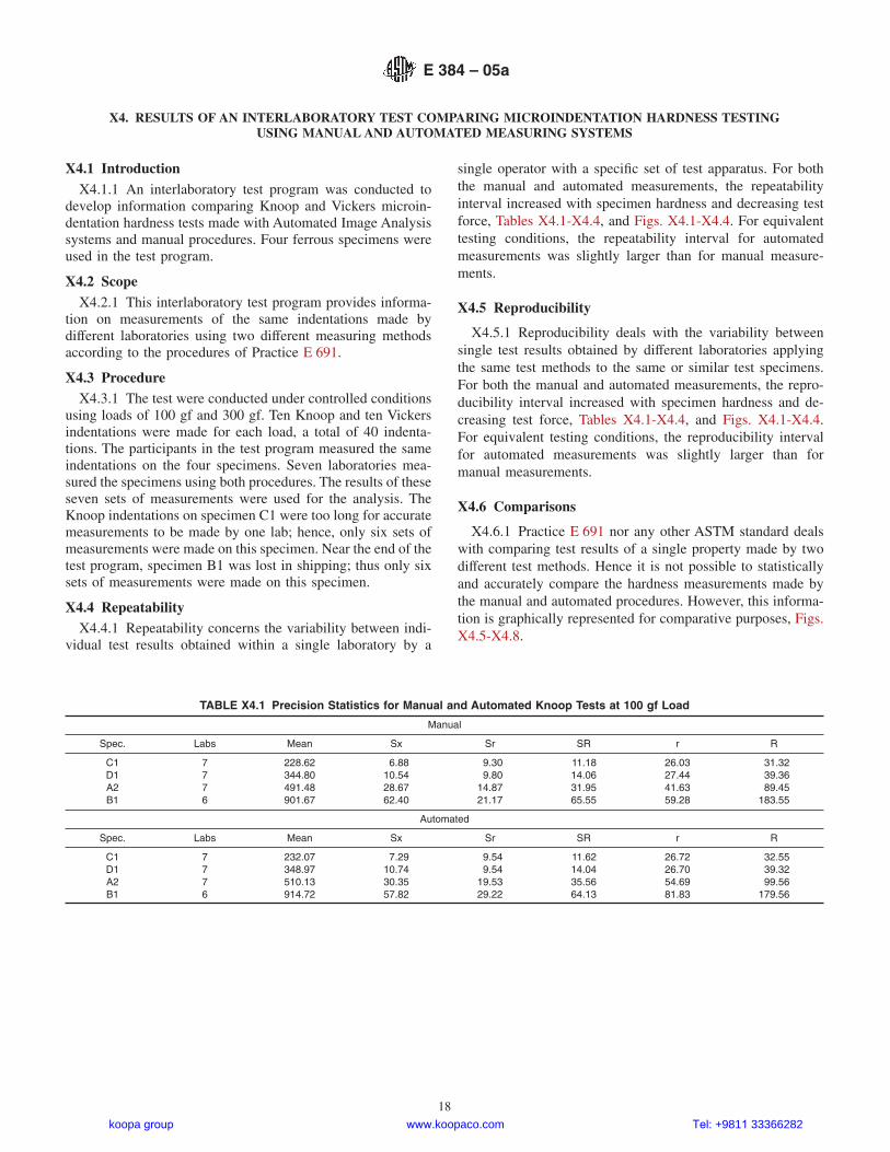
X4. RESULTS OF AN INTERLABORATORY TEST COMPARING MICROINDENTATION HARDNESS TESTINGUSING MANUAL AND AUTOMATED MEASURING SYSTEMS
X4.1 IntroductionX4.1.1 An interlaboratory test program was conducted to
develop information comparing Knoop and Vickers microin-dentation hardness tests made with Automated Image Analysissystems and manual procedures. Four ferrous specimens wereused in the test program.
X4.2 ScopeX4.2.1 This interlaboratory test program provides informa-
tion on measurements of the same indentations made bydifferent laboratories using two different measuring methodsaccording to the procedures of Practice E 691.
X4.3 ProcedureX4.3.1 The test were conducted under controlled conditions
using loads of 100 gf and 300 gf. Ten Knoop and ten Vickersindentations were made for each load, a total of 40 indenta-tions. The participants in the test program measured the sameindentations on the four specimens. Seven laboratories mea-sured the specimens using both procedures. The results of theseseven sets of measurements were used for the analysis. TheKnoop indentations on specimen C1 were too long for accuratemeasurements to be made by one lab; hence, only six sets ofmeasurements were made on this specimen. Near the end of thetest program, specimen B1 was lost in shipping; thus only sixsets of measurements were made on this specimen.
X4.4 RepeatabilityX4.4.1 Repeatability concerns the variability between indi-
vidual test results obtained within a single laboratory by a
single operator with a specific set of test apparatus. For boththe manual and automated measurements, the repeatabilityinterval increased with specimen hardness and decreasing testforce, Tables X4.1-X4.4, and Figs. X4.1-X4.4. For equivalenttesting conditions, the repeatability interval for automatedmeasurements was slightly larger than for manual measure-ments.
X4.5 Reproducibility
X4.5.1 Reproducibility deals with the variability betweensingle test results obtained by different laboratories applyingthe same test methods to the same or similar test specimens.For both the manual and automated measurements, the repro-ducibility interval increased with specimen hardness and de-creasing test force, Tables X4.1-X4.4, and Figs. X4.1-X4.4.For equivalent testing conditions, the reproducibility intervalfor automated measurements was slightly larger than formanual measurements.
X4.6 Comparisons
X4.6.1 Practice E 691 nor any other ASTM standard dealswith comparing test results of a single property made by twodifferent test methods. Hence it is not possible to statisticallyand accurately compare the hardness measurements made bythe manual and automated procedures. However, this informa-tion is graphically represented for comparative purposes, Figs.X4.5-X4.8.
TABLE X4.1 Precision Statistics for Manual and Automated Knoop Tests at 100 gf Load
Manual
Spec. Labs Mean Sx Sr SR r R
C1 7 228.62 6.88 9.30 11.18 26.03 31.32D1 7 344.80 10.54 9.80 14.06 27.44 39.36A2 7 491.48 28.67 14.87 31.95 41.63 89.45B1 6 901.67 62.40 21.17 65.55 59.28 183.55
Automated
Spec. Labs Mean Sx Sr SR r R
C1 7 232.07 7.29 9.54 11.62 26.72 32.55D1 7 348.97 10.74 9.54 14.04 26.70 39.32A2 7 510.13 30.35 19.53 35.56 54.69 99.56B1 6 914.72 57.82 29.22 64.13 81.83 179.56
E 384 – 05a
18koopa group www.koopaco.com Tel: +9811 33366282
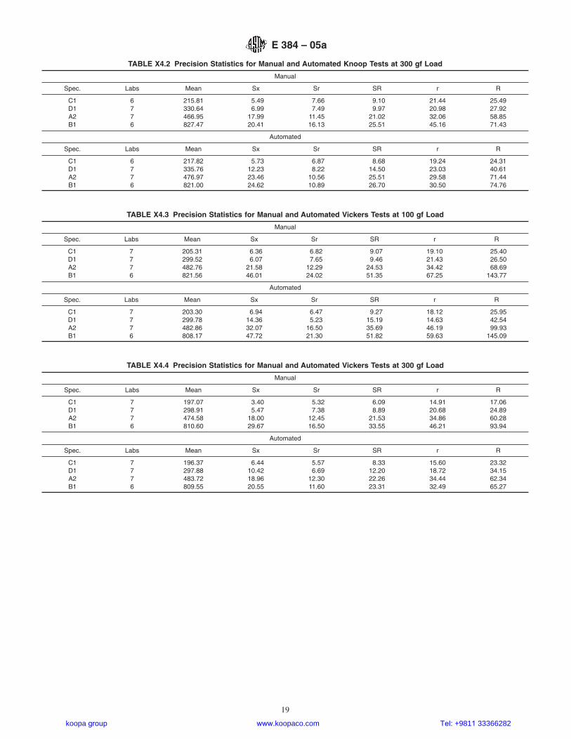
TABLE X4.2 Precision Statistics for Manual and Automated Knoop Tests at 300 gf Load
Manual
Spec. Labs Mean Sx Sr SR r R
C1 6 215.81 5.49 7.66 9.10 21.44 25.49D1 7 330.64 6.99 7.49 9.97 20.98 27.92A2 7 466.95 17.99 11.45 21.02 32.06 58.85B1 6 827.47 20.41 16.13 25.51 45.16 71.43
Automated
Spec. Labs Mean Sx Sr SR r R
C1 6 217.82 5.73 6.87 8.68 19.24 24.31D1 7 335.76 12.23 8.22 14.50 23.03 40.61A2 7 476.97 23.46 10.56 25.51 29.58 71.44B1 6 821.00 24.62 10.89 26.70 30.50 74.76
TABLE X4.3 Precision Statistics for Manual and Automated Vickers Tests at 100 gf Load
Manual
Spec. Labs Mean Sx Sr SR r R
C1 7 205.31 6.36 6.82 9.07 19.10 25.40D1 7 299.52 6.07 7.65 9.46 21.43 26.50A2 7 482.76 21.58 12.29 24.53 34.42 68.69B1 6 821.56 46.01 24.02 51.35 67.25 143.77
Automated
Spec. Labs Mean Sx Sr SR r R
C1 7 203.30 6.94 6.47 9.27 18.12 25.95D1 7 299.78 14.36 5.23 15.19 14.63 42.54A2 7 482.86 32.07 16.50 35.69 46.19 99.93B1 6 808.17 47.72 21.30 51.82 59.63 145.09
TABLE X4.4 Precision Statistics for Manual and Automated Vickers Tests at 300 gf Load
Manual
Spec. Labs Mean Sx Sr SR r R
C1 7 197.07 3.40 5.32 6.09 14.91 17.06D1 7 298.91 5.47 7.38 8.89 20.68 24.89A2 7 474.58 18.00 12.45 21.53 34.86 60.28B1 6 810.60 29.67 16.50 33.55 46.21 93.94
Automated
Spec. Labs Mean Sx Sr SR r R
C1 7 196.37 6.44 5.57 8.33 15.60 23.32D1 7 297.88 10.42 6.69 12.20 18.72 34.15A2 7 483.72 18.96 12.30 22.26 34.44 62.34B1 6 809.55 20.55 11.60 23.31 32.49 65.27
E 384 – 05a
19
koopa group www.koopaco.com Tel: +9811 33366282

FIG. X4.1 Reproducibility of the Knoop 100 gf Manual and Automated Microindentation Hardness Tests
FIG. X4.2 Reproducibility of the Knoop 300 gf Manual and Automated Microindentation Hardness Tests
E 384 – 05a
20koopa group www.koopaco.com Tel: +9811 33366282
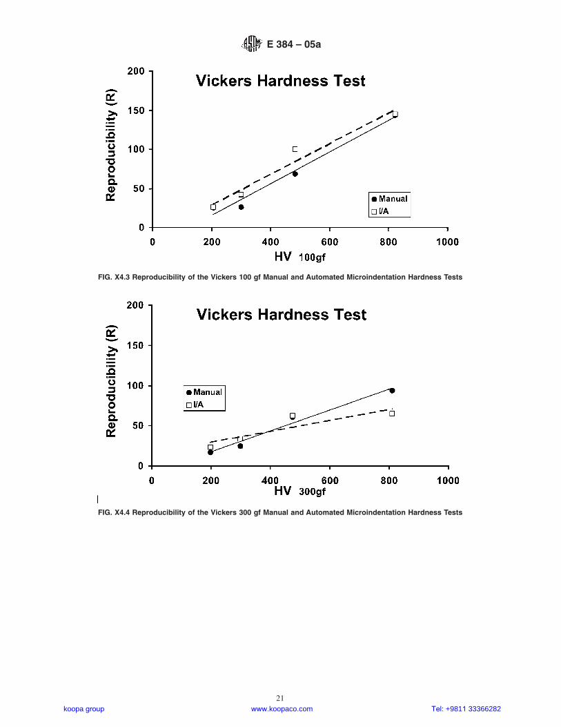
FIG. X4.3 Reproducibility of the Vickers 100 gf Manual and Automated Microindentation Hardness Tests
FIG. X4.4 Reproducibility of the Vickers 300 gf Manual and Automated Microindentation Hardness Tests
E 384 – 05a
21koopa group www.koopaco.com Tel: +9811 33366282
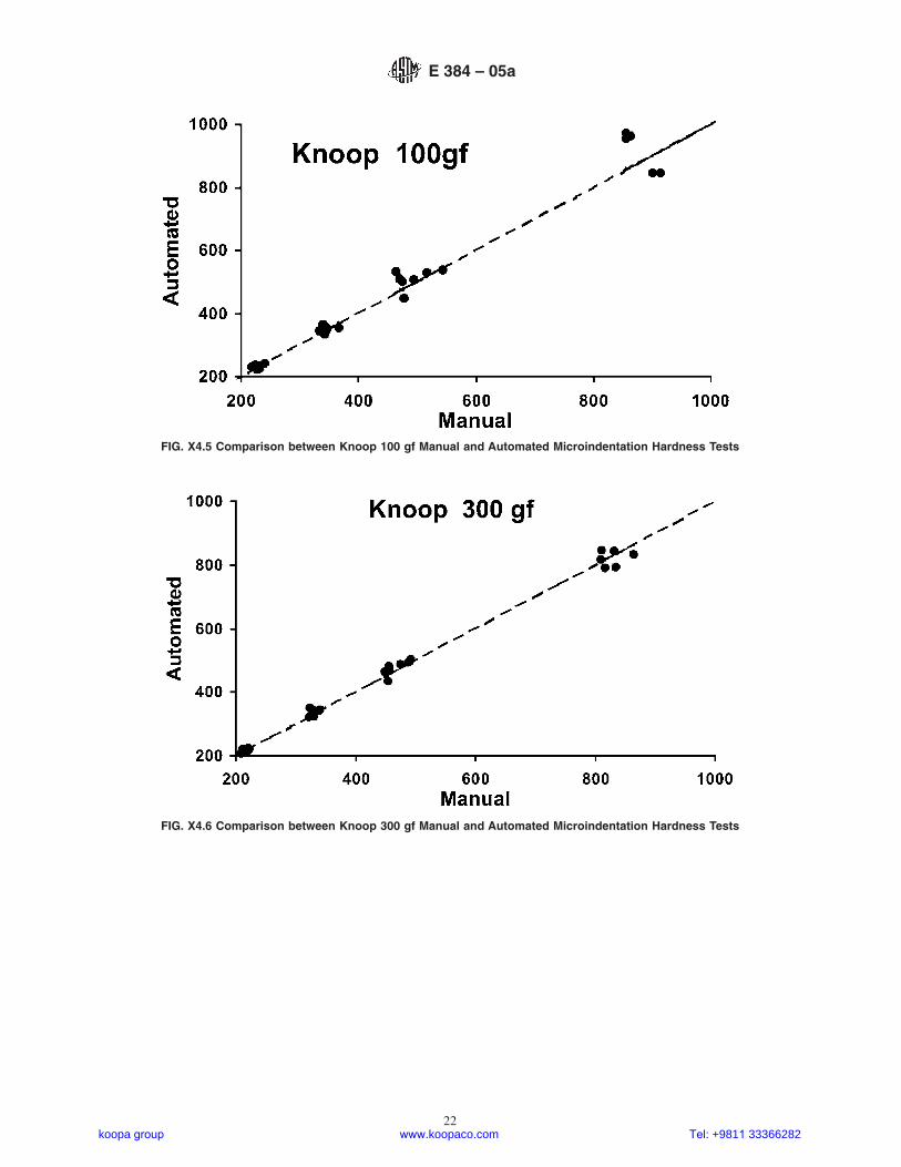
FIG. X4.5 Comparison between Knoop 100 gf Manual and Automated Microindentation Hardness Tests
FIG. X4.6 Comparison between Knoop 300 gf Manual and Automated Microindentation Hardness Tests
E 384 – 05a
22koopa group www.koopaco.com Tel: +9811 33366282

X5. RECOMMENDATIONS FOR LIGHT FORCE MICROINDENTATION HARDNESS TESTING
X5.1 Introduction
X5.1.1 Microindentation hardness of materials can be de-termined using a variety of loads to force the indenter into thetest piece. Testing is considered to be light force when the forcein use produces indentations with a diagonal length of less than20 µm. Both Knoop and Vickers hardness numbers increase inproportion to the inverse of the square of the indentationdiagonal length, Eq 2 and 7. Thus, hardness numbers obtainedfrom indentations with diagonals measuring less than 20 µmare much more sensitive to variations of a few tenths of amicrometre in the actual or measured length of the diagonalsthan hardness numbers obtained by measuring larger indenta-
tions, Eq 12 and 16. Creation of valid indentations, and theaccurate measurement of their diagonals, becomes even moreimperative as the indentations become smaller. For example,consider a material with a Vickers hardness of 500, Table 1. Fora force of 100 gf, the diagonal length would be 19.258 µm. Tomaintain an error of 6 1 %, the accuracy of the diagonalmeasurement must be # 0.096 µm. Similarly for a materialwith a Knoop hardness of 500, when tested with a 20 gf force,the ideal diagonal length would be 23.86 µm, Table 2. Tomaintain an error of 6 1 %, the accuracy of the diagonalmeasurement has to be # 0.12 µm. Measurements to this levelof accuracy are impossible to achieve by optical microscopy.
FIG. X4.7 Comparison between Vickers 100 gf Manual and Automated Microindentation Hardness Tests
FIG. X4.8 Comparison between Vickers 300 gf Manual and Automated Microindentation Hardness Tests
E 384 – 05a
23koopa group www.koopaco.com Tel: +9811 33366282

Because of the inherent difficulties involved in obtaining andmeasuring indentations with diagonals less than 20 µm, and theincreasing effect of possible indentation or measurement er-rors, light force microindentation hardness testing requiresprecautions in addition to those normally necessary. Smallindentations may be due to high test piece hardness or the useof light forces. In either case, some of the concerns involvedwith obtaining accurate hardness results are addressed in thisappendix.
X5.2 Scope
X5.2.1 These recommendations provide guidance and sug-gest additional precautions for microindentation hardness test-ing when the measured diagonals of indentations are less than20 µm.
X5.3 Environment:
X5.3.1 Vibration:X5.3.1.1 Vibration of the microindentation hardness tester
during a light force test can cause a large percentage increasein the measured diagonals. Reasonable accuracy and precisioncan only be achieved when the test instrument is isolated fromvibration as much as possible during testing. Use of anisolation table or isolation platform is mandatory. Airbornevibrations in the vicinity of the test instrument, such as aircurrents and loud noises, are to be avoided.
X5.3.1.2 It is recommended that test instruments not belocated above the ground floor of the building due to theincrease in vibration usually experienced by the upper floors.Test instruments should be located in areas away from machin-ery that may cause low (<20 Hz) frequency vibrations, sincelow frequencies are more easily transmitted through isolationtables and platforms.
X5.3.2 Level—Microindentation hardness testers must belevel in order to obtain usable information. Errors due to minorunleveling become more important as the forces becomelighter.
X5.3.3 Temperature—Control of the temperature of thespecimen, testing instrumentation, and surrounding area shouldbe considered. It is recommended that these temperatures bemaintained at 23 6 3°C. As the length of the measureddiagonal becomes smaller, it may be necessary to increasecontrol of temperature to reduce variability.
X5.4 Specimens
X5.4.1 Specimen Preparation:X5.4.1.1 Usually, test pieces require mounting. Care must
be taken to ensure that the specimens are well supported in themounting material, and that the surface to be tested can beplaced into the test instrument such that it will be normal toboth the loading and optical axes.
X5.4.1.2 The surface properties of the test specimen mustnot be altered due to specimen preparation. Metallographicpolishing, when applicable, should be performed using ac-cepted techniques known to minimize the deformed layerremaining on the surface of the specimen. Light etchingfollowed by light repolishing may be used to further decreasethe thickness of any deformed layer. Electropolishing can
provide surfaces essentially free of deformation due to prepa-ration. Areas to be tested must appear flat in the field of focusof the microscope used to measure the diagonals of theindentations.
X5.4.1.3 The surfaces to be tested should be as clean aspossible. Care must be taken to avoid surface contaminants thatmay be absorbed into the surfaces of some materials such aspolymers or ceramics.
X5.4.2 Microstructure of Specimen—If the microstructureof the material test piece is on the same size scale as theindentation diagonal length, an increase in the variability of thehardness data should be expected. Indentations placed within asingle grain will experience resistance to deformation some-what dependent on the orientation of that grain to the testsurface. Since these orientations are normally random, vari-ability of results is increased. Indentation diagonal lengths canvary depending upon the number of grain boundaries trans-versed by the indentation. Multiphase material systems willprovide indentation diagonal lengths that may be proportionalto the volume percentage of each phase included within thevolume of deformation caused by the indentation. In the abovecases, an increase in the number of measurements taken will benecessary to provide meaningful results.
X5.5 Instruments
X5.5.1 Magnification of Microscope—Classic microinden-tation hardness testers make use of optics that provide magni-fications of up to 800X. Higher magnifications are recom-mended when performing light force testing. Specimens maybe removed from the test instrument following the indentationoperation, and the diagonals of the indentations measuredusing a separate high quality light (or SEM measurements, see4.7.1) microscope capable of providing higher magnifications.
X5.5.2 Optical Quality of Microscope—Use of highly cor-rected objectives with numerical apertures of 0.9 or greater isrecommended. Use of dark field illumination or differentialinterference contrast may improve the contrast of the imageand also enhance the users ability to detect the ends of theindentations.
X5.5.3 Diagonal Measuring Device—The measurementtechnique and the devices used to perform the measurementsshould be capable of discerning differences in length of 0.1 µmor less. In some cases, it may be preferable to obtain aphotomicrograph of the indentation first, and measure thelength of the diagonal as seen in the photomicrograph. In allcases, calibration of magnifications and measuring devices isnecessary.
X5.5.4 Accuracy of Forces—Often, small indentation di-agonal lengths are the result of the use of very light forces, inmany cases less than 10 g. Force accuracy of 6 1 % is requiredin accordance with A3.2. For light forces, this requires that nooils, dust, or other minor contaminants be present. For ex-ample, when using a force of 2.0 g, contaminants with a totalmass of more than 0.02 g render the results of the test invalid,Eq 11.
X5.5.5 Loading Rates—When using light forces, the impactof the indenter on the surface of the test piece can causesignificant inaccuracies to occur. Use of the slowest loadingrate available for each instrument is recommended.
E 384 – 05a
24koopa group www.koopaco.com Tel: +9811 33366282
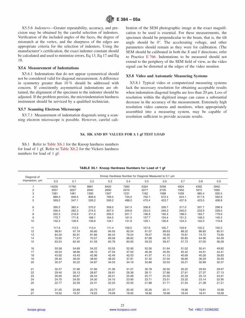
X5.5.6 Indenters—Greater repeatability, accuracy, and pre-cision may be obtained by the careful selection of indenters.Verification of the included angles of the faces, the degree ofmismatch at the vertex, and the sharpness of the edges areappropriate criteria for the selection of indenters. Using themanufacturer’s certification, the exact indenter constant shouldbe calculated and used to minimize errors, Eq 13, Eq 17 and Eq18.
X5.6 Measurement of Indentations
X5.6.1 Indentations that do not appear symmetrical shouldnot be considered valid for diagonal measurement. A differencein symmetry greater than 10 % should be addressed withconcern. If consistently asymmetrical indentations are ob-tained, the alignment of the specimen to the indenter should beadjusted. If the problem persists, the microindentation hardnessinstrument should be serviced by a qualified technician.
X5.7 Scanning Electron Microscope
X5.7.1 Measurement of indentation diagonals using a scan-ning electron microscope is possible. However, careful cali-
bration of the SEM photographic image at the exact magnifi-cation to be used is essential. For these measurements, thespecimen should be perpendicular to the beam, that is, the tiltangle should be 0°. The accelerating voltage, and otherparameters should remain as they were for calibration. (TheSEM should be calibrated in both the X and Y directions; referto Practice E 766. Indentations to be measured should notextend to the periphery of the SEM field of view, as the videosignal can be distorted at the edges of the video monitor.
X5.8 Video and Automatic Measuring Systems
X5.8.1 Typical video or computerized measuring systemslack the necessary resolution for obtaining acceptable resultswhen indentation diagonal lengths are less than 20 µm. Loss ofresolution within the digitized image can cause a substantialdecrease in the accuracy of the measurement. Extremely highresolution video cameras and monitors, when appropriatelyassembled into a measuring system, may be capable ofresolution sufficient to provide accurate results.
X6. HK AND HV VALUES FOR A 1 gf TEST LOAD
X6.1 Refer to Table X6.1 for the Knoop hardness numbersfor load of 1 gf. Refer to Table X6.2 for the Vickers hardnessnumbers for load of 1 gf.
TABLE X6.1 Knoop Hardness Numbers for Load of 1 gf
Diagonal ofImpression, µm
Knoop Hardness Number for Diagonal Measured to 0.1 µm
0.0 0.1 0.2 0.3 0.4 0.5 0.6 0.7 0.8 0.9
1 14230 11760 9881 8420 7260 6324 5558 4924 4392 39422 3557 3227 2940 2690 2470 2277 2105 1952 1815 16923 1581 1481 1390 1307 1231 1162 1098 1039 985.4 935.54 889.3 846.5 806.6 769.5 735.0 702.7 672.4 644.1 617.6 592.65 569.2 547.1 526.2 506.2 488.0 470.4 453.7 437.9 423.0 408.8
6 395.2 382.4 370.2 358.5 347.4 336.8 326.7 317.0 307.7 298.97 290.4 282.3 274.5 267.0 259.8 253.0 246.3 240.0 233.9 228.08 222.3 216.9 211.6 206.5 201.7 196.9 192.4 188.0 183.7 179.69 175.7 171.8 168.1 164.5 161.0 157.7 154.4 151.2 148.2 145.2
10 142.3 139.5 136.8 134.1 131.6 129.1 126.6 124.3 122.0 119.8
11 117.6 115.5 113.4 111.4 109.5 107.6 105.7 103.9 102.2 100.512 98.81 97.19 95.60 94.05 92.54 91.07 89.63 88.22 86.85 85.5113 84.20 82.91 81.66 80.44 79.24 78.07 76.93 75.81 74.72 73.6514 72.60 71.57 70.57 69.58 68.62 67.68 66.75 65.85 64.96 64.0915 63.24 62.40 61.59 60.78 60.00 59.23 58.47 57.73 57.00 56.28
16 55.58 54.89 54.22 53.55 52.90 52.26 51.64 51.02 50.41 49.8217 49.24 48.66 48.10 47.54 47.00 46.46 45.94 45.42 44.91 44.4118 43.92 43.43 42.96 42.49 42.03 41.57 41.13 40.69 40.26 39.8319 39.42 39.00 38.60 38.20 37.81 37.42 37.04 36.66 36.29 35.9320 35.57 35.22 34.87 34.53 34.19 33.86 33.53 33.21 32.89 32.57
21 32.27 31.96 31.66 31.36 31.07 30.78 30.50 30.22 29.94 29.6722 29.40 29.13 28.87 28.61 28.36 28.11 27.86 27.61 27.37 27.1323 26.90 26.67 26.44 26.21 25.99 25.77 25.55 25.33 25.12 24.9124 24.70 24.50 24.30 24.10 23.90 23.71 23.51 23.32 23.14 22.9525 22.77 22.59 22.41 22.23 22.05 21.88 21.71 21.54 21.38 21.21
26 21.05 20.89 20.73 20.57 20.42 20.26 20.11 19.96 19.81 19.6627 19.52 19.37 19.23 19.09 18.95 18.82 18.68 18.54 18.41 18.28
E 384 – 05a
25koopa group www.koopaco.com Tel: +9811 33366282
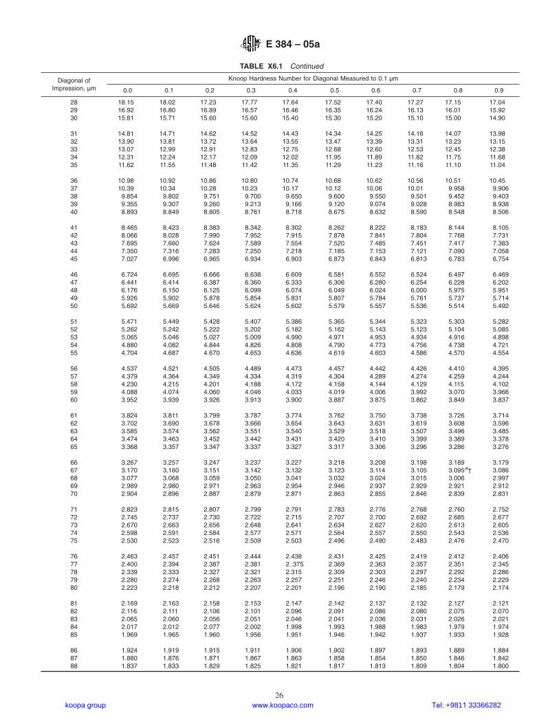
TABLE X6.1 Continued
Diagonal ofImpression, µm
Knoop Hardness Number for Diagonal Measured to 0.1 µm
0.0 0.1 0.2 0.3 0.4 0.5 0.6 0.7 0.8 0.9
28 18.15 18.02 17.23 17.77 17.64 17.52 17.40 17.27 17.15 17.0429 16.92 16.80 16.89 16.57 16.46 16.35 16.24 16.13 16.01 15.9230 15.81 15.71 15.60 15.60 15.40 15.30 15.20 15.10 15.00 14.90
31 14.81 14.71 14.62 14.52 14.43 14.34 14.25 14.16 14.07 13.9832 13.90 13.81 13.72 13.64 13.55 13.47 13.39 13.31 13.23 13.1533 13.07 12.99 12.91 12.83 12.75 12.68 12.60 12.53 12.45 12.3834 12.31 12.24 12.17 12.09 12.02 11.95 11.89 11.82 11.75 11.6835 11.62 11.55 11.48 11.42 11.35 11.29 11.23 11.16 11.10 11.04
36 10.98 10.92 10.86 10.80 10.74 10.68 10.62 10.56 10.51 10.4537 10.39 10.34 10.28 10.23 10.17 10.12 10.06 10.01 9.958 9.90638 9.854 9.802 9.751 9.700 9.650 9.600 9.550 9.501 9.452 9.40339 9.355 9.307 9.260 9.213 9.166 9.120 9.074 9.028 8.983 8.93840 8.893 8.849 8.805 8.761 8.718 8.675 8.632 8.590 8.548 8.506
41 8.465 8.423 8.383 8.342 8.302 8.262 8.222 8.183 8.144 8.10542 8.066 8.028 7.990 7.952 7.915 7.878 7.841 7.804 7.768 7.73143 7.695 7.660 7.624 7.589 7.554 7.520 7.485 7.451 7.417 7.38344 7.350 7.316 7.283 7.250 7.218 7.185 7.153 7.121 7.090 7.05845 7.027 6.996 6.965 6.934 6.903 6.873 6.843 6.813 6.783 6.754
46 6.724 6.695 6.666 6.638 6.609 6.581 6.552 6.524 6.497 6.46947 6.441 6.414 6.387 6.360 6.333 6.306 6.280 6.254 6.228 6.20248 6.176 6.150 6.125 6.099 6.074 6.049 6.024 6.000 5.975 5.95149 5.926 5.902 5.878 5.854 5.831 5.807 5.784 5.761 5.737 5.71450 5.692 5.669 5.646 5.624 5.602 5.579 5.557 5.536 5.514 5.492
51 5.471 5.449 5.428 5.407 5.386 5.365 5.344 5.323 5.303 5.28252 5.262 5.242 5.222 5.202 5.182 5.162 5.143 5.123 5.104 5.08553 5.065 5.046 5.027 5.009 4.990 4.971 4.953 4.934 4.916 4.89854 4.880 4.082 4.844 4.826 4.808 4.790 4.773 4.756 4.738 4.72155 4.704 4.687 4.670 4.653 4.636 4.619 4.603 4.586 4.570 4.554
56 4.537 4.521 4.505 4.489 4.473 4.457 4.442 4.426 4.410 4.39557 4.379 4.364 4.349 4.334 4.319 4.304 4.289 4.274 4.259 4.24458 4.230 4.215 4.201 4.188 4.172 4.158 4.144 4.129 4.115 4.10259 4.088 4.074 4.060 4.046 4.033 4.019 4.006 3.992 3.070 3.96660 3.952 3.939 3.926 3.913 3.900 3.887 3.875 3.862 3.849 3.837
61 3.824 3.811 3.799 3.787 3.774 3.762 3.750 3.738 3.726 3.71462 3.702 3.690 3.678 3.666 3.654 3.643 3.631 3.619 3.608 3.59663 3.585 3.574 3.562 3.551 3.540 3.529 3.518 3.507 3.496 3.48564 3.474 3.463 3.452 3.442 3.431 3.420 3.410 3.399 3.389 3.37865 3.368 3.357 3.347 3.337 3.327 3.317 3.306 3.296 3.286 3.276
66 3.267 3.257 3.247 3.237 3.227 3.218 3.208 3.198 3.189 3.17967 3.170 3.160 3.151 3.142 3.132 3.123 3.114 3.105 3.095A† 3.08668 3.077 3.068 3.059 3.050 3.041 3.032 3.024 3.015 3.006 2.99769 2.989 2.980 2.971 2.963 2.954 2.946 2.937 2.929 2.921 2.91270 2.904 2.896 2.887 2.879 2.871 2.863 2.855 2.846 2.839 2.831
71 2.823 2.815 2.807 2.799 2.791 2.783 2.776 2.768 2.760 2.75272 2.745 2.737 2.730 2.722 2.715 2.707 2.700 2.692 2.685 2.67773 2.670 2.663 2.656 2.648 2.641 2.634 2.627 2.620 2.613 2.60574 2.598 2.591 2.584 2.577 2.571 2.564 2.557 2.550 2.543 2.53675 2.530 2.523 2.516 2.509 2.503 2.496 2.490 2.483 2.476 2.470
76 2.463 2.457 2.451 2.444 2.438 2.431 2.425 2.419 2.412 2.40677 2.400 2.394 2.387 2.381 2..375 2.369 2.363 2.357 2.351 2.34578 2.339 2.333 2.327 2.321 2.315 2.309 2.303 2.297 2.292 2.28679 2.280 2.274 2.268 2.263 2.257 2.251 2.246 2.240 2.234 2.22980 2.223 2.218 2.212 2.207 2.201 2.196 2.190 2.185 2.179 2.174
81 2.169 2.163 2.158 2.153 2.147 2.142 2.137 2.132 2.127 2.12182 2.116 2.111 2.106 2.101 2.096 2.091 2.086 2.080 2.075 2.07083 2.065 2.060 2.056 2.051 2.046 2.041 2.036 2.031 2.026 2.02184 2.017 2.012 2.077 2.002 1.998 1.993 1.988 1.983 1.979 1.97485 1.969 1.965 1.960 1.956 1.951 1.946 1.942 1.937 1.933 1.928
86 1.924 1.919 1.915 1.911 1.906 1.902 1.897 1.893 1.889 1.88487 1.880 1.876 1.871 1.867 1.863 1.858 1.854 1.850 1.846 1.84288 1.837 1.833 1.829 1.825 1.821 1.817 1.813 1.809 1.804 1.800
E 384 – 05a
26koopa group www.koopaco.com Tel: +9811 33366282

TABLE X6.1 Continued
Diagonal ofImpression, µm
Knoop Hardness Number for Diagonal Measured to 0.1 µm
0.0 0.1 0.2 0.3 0.4 0.5 0.6 0.7 0.8 0.9
89 1.796 1.792 1.788 1.784 1.780 1.776 1.772 1.768 1.765 1.76190 1.757 1.753 1.749 1.745 1.741 1.737 1.733 1.730 1.726 1.722
91 1.718 1.715 1.711 1.707 1.703 1.700 1.696 1.692 1.688 1.68592 1.681 1.677 1.674 1.670 1.667 1.663 1.659 1.656 1.652 1.64993 1.654 1.642 1.638 1.635 1.631 1.628 1.624 1.621 1.617 1.61494 1.610 1.607 1.604 1.600 1.597 1.593 1.590 1.587 1.583 1.58095 1.577 1.573 1.570 1.567 1.563 1.560 1.557 1.554 1.550 1.547
96 1.544 1.541 1.538 1.534 1.531 1.528 1.525 1.522 1.519 1.51597 1.512 1.509 1.506 1.503 1.500 1.497 1.494 1.491 1.488 1.48598 1.482 1.479 1.476 1.473 1.470 1.467 1.464 1.461 1.458 1.45599 1.452 1.449 1.446 1.443 1.440 1.437 1.434 1.431 1.429 1.426
100 1.423 1.420 1.417 1.413 1.412 1.409 1.406 1.403 1.400 1.398
101 1.395 1.392 1.389 1.387 1.384 1.381 1.378 1.376 1.373 1.370102 1.368 1.365 1.362 1.360 1.357 1.354 1.352 1.349 1.346 1.344103 1.341 1.339 1.336 1.333 1.331 1.328 1.326 1.323 1.321 1.318104 1.316 1.313 1.311 1.308 1.305 1.303 1.301 1.298 1.296 1.293105 1.291 1.288 1.286 1.283 1.281 1.278 1.276 1.274 1.271 1.269
106 1.266 1.264 1.262 1.259 1.257 1.255 1.252 1.250 1.247 1.245107 1.243 1.240 1.238 1.236 1.234 1.231 1.229 1.227 1.224 1.222108 1.220 1.218 1.215 1.213 1.211 1.209 1.206 1.204 1.202 1.200109 1.198 1.195 1.193 1.191 1.189 1.187 1.185 1.182 1.180 1.178110 1.176 1.174 1.172 1.170 1.167 1.165 1.163 1.161 1.159 1.157
111 1.155 1.153 1.151 1.149 1.147 1.145 1.142 1.140 1.138 1.136112 1.134 1.132 1.130 1.128 1.126 1.124 1.122 1.120 1.118 1.116113 1.114 1.112 1.110 1.108 1.106 1.105 1.103 1.101 1.099 1.097114 1.095 1.093 1.091 1.089 1.087 1.085 1.083 1.082 1.080 1.078115 1.076 1.074 1.072 1.070 1.068 1.067 1.065 1.063 1.061 1.059
116 1.057 1.056 1.054 1.052 1.050 1.048 1.047 1.045 1.043 1.041117 1.039 1.038 1.036 1.034 1.032 1.031 1.029 1.027 1.025 1.024118 1.022 1.020 1.018 1.017 1.015 1.013 1.012 1.010 1.008 1.006119 1.005 1.003 1.001 0.9998 0.9981 0.9964 0.9947 0.9931 0.9914 0.9898120 0.9881 0.9865 0.9848 0.9832 0.9816 0.9799 0.9783 0.9767 0.9751 0.9735
121 0.9719 0.9703 0.9687 0.9671 0.9655 0.9639 0.9623 0.9607 0.9591 0.9576122 0.9560 0.9544 0.9529 0.9513 0.9498 0.9482 0.9467 0.9451 0.9436 0.9420123 0.9405 0.9390 0.9375 0.9359 0.9344 0.9329 0.9314 0.9299 0.9284 0.9269124 0.9254 0.9239 0.9224 0.9209 0.9195 0.9180 0.9165 0.9150 0.9136 0.9121125 0.9107 0.9092 0.9078 0.9063 0.9049 0.9034 0.9020 0.9005 0.8991 0.8977
126 0.8963 0.8948 0.8934 0.8920 0.8906 0.8892 0.8878 0.8864 0.8850 0.8836127 0.8822 0.8808 0.8794 0.8780 0.8767 0.8753 0.8739 0.8726 0.8712 0.8698128 0.8685 0.8671 0.8658 0.8644 0.8631 0.8617 0.8604 0.8591 0.8577 0.8564129 0.8551 0.8537 0.8524 0.8511 0.8498 0.8485 0.8472 0.8459 0.8446 0.8433130 0.8420 0.8407 0.8394 0.8381 0.8368 0.8355 0.8343 0.8330 0.8317 0.8304
131 0.8291 0.8279 0.8266 0.8254 0.8241 0.8229 0.8216 0.8204 0.8191 0.8179132 0.8166 0.8154 0.8142 0.8129 0.8117 0.8105 0.8093 0.8080 0.8068 0.8056133 0.8044 0.8032 0.8020 0.8008 0.7996 0.7984 0.7972 0.7960 0.7948 0.7936134 0.7924 0.7913 0.7901 0.7889 0.7877 0.7866 0.7854 0.7842 0.7831 0.7819135 0.7807 0.7796 0.7784 0.7773 0.7761 0.7750 0.7738 0.7727 0.7716 0.7704
136 0.7693 0.7682 0.7670 0.7659 0.7648 0.7637 0.7626 0.7614 0.7603 0.7592137 0.7581 0.7570 0.7559 0.7548 0.7537 0.7526 0.7515 0.7504 0.7493 0.7483138 0.7472 0.7461 0.7450 0.7439 0.7429 0.7418 0.7407 0.7396 0.7386 0.7375139 0.7365 0.7354 0.7343 0.7333 0.7322 0.7312 0.7301 0.7291 0.7281 0.7270140 0.7260 0.7249 0.7239 0.7229 0.7218 0.7208 0.7198 0.7188 0.7177 0.7167
141 0.7157 0.7147 0.7137 0.7127 0.7117 0.7107 0.7097 0.7087 0.7077 0.7067142 0.7057 0.7047 0.7037 0.7027 0.7017 0.7007 0.6997 0.6988 0.6978 0.6968143 0.6958 0.6949 0.6939 0.6929 0.6920 0.6910 0.6900 0.6891 0.6881 0.6872144 0.6862 0.6852 0.6843 0.6834 0.6824 0.6815 0.6805 0.6796 0.6786 0.6777145 0.6768 0.6758 0.6749 0.6740 0.6731 0.6721 0.6712 0.6703 0.6694 0.6684
146 0.6675 0.6666 0.6657 0.6648 0.6639 0.6630 0.6621 0.6612 0.6603 0.6594147 0.6585 0.6576 0.6567 0.6558 0.6549 0.6540 0.6531 0.6523 0.6514 0.6505148 0.6496 0.6487 0.6479 0.6470 0.6461 0.6452 0.6444 0.6435 0.6426 0.6418149 0.6409 0.6401 0.6392 0.6383 0.6375 0.6366 0.6358 0.6349 0.6341 0.6332
E 384 – 05a
27koopa group www.koopaco.com Tel: +9811 33366282
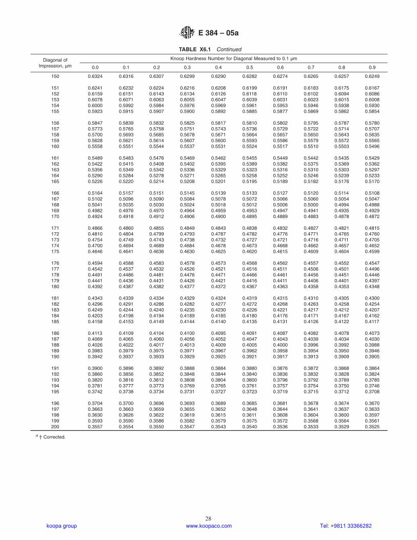
TABLE X6.1 Continued
Diagonal ofImpression, µm
Knoop Hardness Number for Diagonal Measured to 0.1 µm
0.0 0.1 0.2 0.3 0.4 0.5 0.6 0.7 0.8 0.9
150 0.6324 0.6316 0.6307 0.6299 0.6290 0.6282 0.6274 0.6265 0.6257 0.6249
151 0.6241 0.6232 0.6224 0.6216 0.6208 0.6199 0.6191 0.6183 0.6175 0.6167152 0.6159 0.6151 0.6143 0.6134 0.6126 0.6118 0.6110 0.6102 0.6094 0.6086153 0.6078 0.6071 0.6063 0.6055 0.6047 0.6039 0.6031 0.6023 0.6015 0.6008154 0.6000 0.5992 0.5984 0.5976 0.5969 0.5961 0.5953 0.5946 0.5938 0.5930155 0.5923 0.5915 0.5907 0.5900 0.5892 0.5885 0.5877 0.5869 0.5862 0.5854
156 0.5847 0.5839 0.5832 0.5825 0.5817 0.5810 0.5802 0.5795 0.5787 0.5780157 0.5773 0.5765 0.5758 0.5751 0.5743 0.5736 0.5729 0.5722 0.5714 0.5707158 0.5700 0.5693 0.5685 0.5678 0.5671 0.5664 0.5657 0.5650 0.5643 0.5635159 0.5628 0.5621 0.5614 0.5607 0.5600 0.5593 0.5586 0.5579 0.5572 0.5565160 0.5558 0.5551 0.5544 0.5537 0.5531 0.5524 0.5517 0.5510 0.5503 0.5496
161 0.5489 0.5483 0.5476 0.5469 0.5462 0.5455 0.5449 0.5442 0.5435 0.5429162 0.5422 0.5415 0.5408 0.5402 0.5395 0.5389 0.5382 0.5375 0.5369 0.5362163 0.5356 0.5349 0.5342 0.5336 0.5329 0.5323 0.5316 0.5310 0.5303 0.5297164 0.5290 0.5284 0.5278 0.5271 0.5265 0.5258 0.5252 0.5246 0.5239 0.5233165 0.5226 0.5220 0.5214 0.5208 0.5201 0.5195 0.5189 0.5182 0.5176 0.5170
166 0.5164 0.5157 0.5151 0.5145 0.5139 0.5133 0.5127 0.5120 0.5114 0.5108167 0.5102 0.5096 0.5090 0.5084 0.5078 0.5072 0.5066 0.5060 0.5054 0.5047168 0.5041 0.5035 0.5030 0.5024 0.5018 0.5012 0.5006 0.5000 0.4994 0.4988169 0.4982 0.4976 0.4970 0.4964 0.4959 0.4953 0.4947 0.4941 0.4935 0.4929170 0.4924 0.4918 0.4912 0.4906 0.4900 0.4895 0.4889 0.4883 0.4878 0.4872
171 0.4866 0.4860 0.4855 0.4849 0.4843 0.4838 0.4832 0.4827 0.4821 0.4815172 0.4810 0.4804 0.4799 0.4793 0.4787 0.4782 0.4776 0.4771 0.4765 0.4760173 0.4754 0.4749 0.4743 0.4738 0.4732 0.4727 0.4721 0.4716 0.4711 0.4705174 0.4700 0.4694 0.4689 0.4684 0.4678 0.4673 0.4668 0.4662 0.4657 0.4652175 0.4646 0.4641 0.4636 0.4630 0.4625 0.4620 0.4615 0.4609 0.4604 0.4599
176 0.4594 0.4588 0.4583 0.4578 0.4573 0.4568 0.4562 0.4557 0.4552 0.4547177 0.4542 0.4537 0.4532 0.4526 0.4521 0.4516 0.4511 0.4506 0.4501 0.4496178 0.4491 0.4486 0.4481 0.4476 0.4471 0.4466 0.4461 0.4456 0.4451 0.4446179 0.4441 0.4436 0.4431 0.4426 0.4421 0.4416 0.4411 0.4406 0.4401 0.4397180 0.4392 0.4387 0.4382 0.4377 0.4372 0.4367 0.4363 0.4358 0.4353 0.4348
181 0.4343 0.4339 0.4334 0.4329 0.4324 0.4319 0.4315 0.4310 0.4305 0.4300182 0.4296 0.4291 0.4286 0.4282 0.4277 0.4272 0.4268 0.4263 0.4258 0.4254183 0.4249 0.4244 0.4240 0.4235 0.4230 0.4226 0.4221 0.4217 0.4212 0.4207184 0.4203 0.4198 0.4194 0.4189 0.4185 0.4180 0.4176 0.4171 0.4167 0.4162185 0.4158 0.4153 0.4149 0.4144 0.4140 0.4135 0.4131 0.4126 0.4122 0.4117
186 0.4113 0.4109 0.4104 0.4100 0.4095 0.4091 0.4087 0.4082 0.4078 0.4073187 0.4069 0.4065 0.4060 0.4056 0.4052 0.4047 0.4043 0.4039 0.4034 0.4030188 0.4026 0.4022 0.4017 0.4013 0.4009 0.4005 0.4000 0.3996 0.3992 0.3988189 0.3983 0.3979 0.3975 0.3971 0.3967 0.3962 0.3958 0.3954 0.3950 0.3946190 0.3942 0.3937 0.3933 0.3929 0.3925 0.3921 0.3917 0.3913 0.3909 0.3905
191 0.3900 0.3896 0.3892 0.3888 0.3884 0.3880 0.3876 0.3872 0.3868 0.3864192 0.3860 0.3856 0.3852 0.3848 0.3844 0.3840 0.3836 0.3832 0.3828 0.3824193 0.3820 0.3816 0.3812 0.3808 0.3804 0.3800 0.3796 0.3792 0.3789 0.3785194 0.3781 0.3777 0.3773 0.3769 0.3765 0.3761 0.3757 0.3754 0.3750 0.3746195 0.3742 0.3738 0.3734 0.3731 0.3727 0.3723 0.3719 0.3715 0.3712 0.3708
196 0.3704 0.3700 0.3696 0.3693 0.3689 0.3685 0.3681 0.3678 0.3674 0.3670197 0.3663 0.3663 0.3659 0.3655 0.3652 0.3648 0.3644 0.3641 0.3637 0.3633198 0.3630 0.3626 0.3622 0.3619 0.3615 0.3611 0.3608 0.3604 0.3600 0.3597199 0.3593 0.3590 0.3586 0.3582 0.3579 0.3575 0.3572 0.3568 0.3564 0.3561200 0.3557 0.3554 0.3550 0.3547 0.3543 0.3540 0.3536 0.3533 0.3529 0.3525
A † Corrected.
E 384 – 05a
28koopa group www.koopaco.com Tel: +9811 33366282

TABLE X6.2 Vickers Hardness Numbers for Load of 1 gf
Diagonal ofImpression, µm
Vickers Hardness Number for Diagonal Measured to 0.1 µm
0.0 0.1 0.2 0.3 0.4 0.5 0.6 0.7 0.8 0.9
1 1854.6 1533.5 1288 1097.5 946.1 824.2 724.4 641.6 572.3 513.72 463.0 420.0 383.1 350.3 321.9 296.7 274.3 254.4 236.5 220.53 206.9 193.3 181.1 170.3 160.4 151.4 143.1 135.5 128.4 121.94 115.17 110.29 105.58 100.01 95.78 91.57 87.64 83.95 80.48 77.235 74 71 68 66 63.59 61.30 59.13 57.07 55.12 53.27
6 51.51 49.83 48.24 46.72 45.27 43.89 42.57 41.31 40.10 38.957 37.84 36.79 35.77 34.80 33.86 32.97 32.10 31.28 30.48 29.718 28.97 28.26 27.58 26.92 26.28 25.67 25.07 24.50 23.95 23.419 22.89 22.39 21.91 21.44 20.99 20.55 20.12 19.71 19.31 18.92
10 18.54 18.18 17.82 17.48 17.14 16.82 16.50 16.20 15.90 15.61
11 15.33 15.05 14.78 14.52 14.27 14.02 13.78 13.55 13.32 13.0912 12.88 12.67 12.46 12.26 12.06 11.87 11.68 11.50 11.32 11.1413 10.97 10.81 10.64 10.48 10.33 10.17 10.03 9.880 9.737 9.59814 9.461 9.327 9.196 9.068 8.943 8.820 8.699 8.581 8.466 8.35315 8.242 8.133 8.026 7.922 7.819 7.718 7.620 7.523 7.428 7.335
16 7.244 7.154 7.066 6.979 6.895 6.811 6.729 6.649 6.570 6.49317 6.416 6.342 6.268 6.196 6.125 6.055 5.986 5.919 5.853 5.78718 5.723 5.660 5.598 5.537 5.477 5.418 5.360 5.303 5.247 5.19119 5.137 5.083 5.030 4.978 4.927 4.877 4.827 4.778 4.730 4.68320 4.636 4.590 4.545 4.500 4.456 4.413 4.370 4.328 4.286 4.245
21 4.205 4.165 4.126 4.087 4.049 4.012 3.975 3.938 3.902 3.86622 3.831 3.797 3.763 3.729 3.696 3.663 3.631 3.599 3.587 3.53623 3.505 3.475 3.445 3.416 3.387 3.358 3.329 3.301 3.274 3.24624 3.219 3.193 3.166 3.140 3.115 3.089 3.064 3.039 3.015 2.99125 2.967 2.943 2.920 2.897 2.874 2.852 2.830 2.808 2.786 2.764
26 2.743 2.722 2.701 2.681 2.661 2.641 2.621 2.601 2.582 2.56327 2.544 2.525 2.506 2.488 2.470 2.452 2.434 2.417 2.399 2.38228 2.365 2.348 2.332 2.315 2.299 2.283 2.267 2.251 2.236 2.22029 2.205 2.190 2.175 2.160 2.145 2.131 2.116 2.102 2.088 2.07430 2.060 2.047 2.033 2.020 2.007 1.993 1.980 1.968 1.955 1.942
31 1.930 1.917 1.905 1.893 1.881 1.869 1.857 1.845 1.834 1.82232 1.811 1.800 1.788 1.777 1.766 1.756 1.745 1.734 1.724 1.71333 1.703 1.693 1.682 1.672 1.662 1.652 1.643 1.633 1.623 1.61434 1.604 1.595 1.585 1.576 1.567 1.558 1.549 1.540 1.531 1.52235 1.514 1.505 1.497 1.488 1.480 1.471 1.463 1.455 1.447 1.439
36 1.431 1.423 1.415 1.407 1.400 1.392 1.384 1.377 1.369 1.36237 1.355 1.347 1.340 1.333 1.326 1.319 1.312 1.305 1.298 1.29138 1.284 1.277 1.271 1.264 1.258 1.251 1.245 1.238 1.232 1.22539 1.219 1.213 1.207 1.201 1.195 1.189 1.183 1.177 1.171 1.16540 1.159 1.153 1.147 1.142 1.136 1.131 1.125 1.119 1.114 1.109
41 1.103 1.098 1.092 1.087 1.082 1.077 1.072 1.066 1.061 1.05642 1.051 1.046 1.041 1.036 1.031 1.027 1.022 1.017 1.012 1.00843 0.003 0.9983 0.9936 0.9891 0.9845 0.9800 0.9755 0.9710 0.9666 0.962244 0.9578 0.9535 0.9492 0.9449 0.9407 0.9364 0.9322 0.9281 0.9239 0.919845 0.9157 0.9117 0.9077 0.9036 0.8997 0.8957 0.8918 0.8879 0.8840 0.8802
46 0.8764 0.8726 0.8688 0.8650 0.8613 0.8576 0.8539 0.8503 0.8467 0.843047 0.8395 0.8359 0.8324 0.8288 0.8254 0.8219 0.8184 0.8150 0.8116 0.808248 0.8048 0.8015 0.7982 0.7949 0.7916 0.7883 0.7851 0.7819 0.7787 0.775549 0.7723 0.7692 0.7661 0.7630 0.7599 0.7568 0.7538 0.7507 0.7477 0.744750 0.7417 0.7388 0.7359 0.7329 0.7300 0.7271 0.7243 0.7214 0.7186 0.7158
51 0.7129 0.7102 0.7074 0.7046 0.7019 0.6992 0.6965 0.6938 0.6911 0.688452 0.6858 0.6832 0.6805 0.6779 0.6754 0.6728 0.6702 0.6677 0.6652 0.662753 0.6602 0.6577 0.6552 0.6527 0.6503 0.6479 0.6455 0.6431 0.6407 0.638354 0.6359 0.6336 0.6312 0.6289 0.6266 0.6243 0.6220 0.6198 0.6175 0.615355 0.6130 0.6108 0.6086 0.6064 0.6042 0.6020 0.5999 0.5977 0.5956 0.5934
56 0.5913 0.5892 0.5871 0.5850 0.5830 0.5809 0.5788 0.5768 0.5748 0.572857 0.5708 0.5688 0.5668 0.5648 0.5628 0.5609 0.5589 0.5570 0.5551 0.553158 0.5512 0.5493 0.5475 0.5456 0.5437 0.5419 0.5400 0.5382 0.5363 0.534559 0.5327 0.5309 0.5291 0.5273 0.5256 0.5238 0.5220 0.5203 0.5186 0.516860 0.5151 0.5134 0.5117 0.5100 0.5083 0.5066 0.5050 0.5033 0.5016 0.5000
E 384 – 05a
29koopa group www.koopaco.com Tel: +9811 33366282

TABLE X6.2 Continued
Diagonal ofImpression, µm
Vickers Hardness Number for Diagonal Measured to 0.1 µm
0.0 0.1 0.2 0.3 0.4 0.5 0.6 0.7 0.8 0.9
61 0.4984 0.4967 0.4951 0.4935 0.4919 0.4903 0.4887 0.4871 0.4855 0.484062 0.4824 0.4809 0.4793 0.4778 0.4762 0.4747 0.4732 0.4717 0.4702 0.468763 0.4672 0.4657 0.4643 0.4628 0.4613 0.4599 0.4584 0.4570 0.4556 0.454164 0.4527 0.4513 0.4499 0.4485 0.4471 0.4457 0.4444 0.4430 0.4416 0.440365 0.4389 0.4376 0.4362 0.4349 0.4336 0.4322 0.4309 0.4296 0.4283 0.4270
66 0.4257 0.4244 0.4231 0.4219 0.4206 0.4193 0.4181 0.4168 0.4156 0.414367 0.4131 0.4119 0.4106 0.4094 0.4082 0.4070 0.4058 0.4046 0.4034 0.402268 0.4010 0.3999 0.3987 0.3975 0.3964 0.3952 0.3941 0.3929 0.3918 0.390669 0.3895 0.3884 0.3872 0.3861 0.3850 0.3839 0.3828 0.3817 0.3806 0.379570 0.3784 0.3774 0.3763 0.3752 0.3742 0.3731 0.3720 0.3710 0.3699 0.3689
71 0.3679 0.3668 0.3658 0.3648 0.3638 0.3627 0.3617 0.3607 0.3597 0.358772 0.3577 0.3567 0.3557 0.3548 0.3538 0.3528 0.3518 0.3509 0.3499 0.348973 0.3480 0.3470 0.3461 0.3451 0.3442 0.3433 0.3423 0.3414 0.3405 0.339674 0.3386 0.3377 0.3368 0.3359 0.3350 0.3341 0.3332 0.3323 0.3314 0.330575 0.3297 0.3288 0.3279 0.3270 0.3262 0.3253 0.3245 0.3236 0.3227 0.3219
76 0.3211 0.3202 0.3194 0.3185 0.3177 0.3169 0.3160 0.3152 0.3144 0.313677 0.3128 0.3120 0.3111 0.3103 0.3095 0.3087 0.3079 0.3072 0.3064 0.305678 0.3048 0.3040 0.3032 0.3025 0.3017 0.3009 0.3002 0.2994 0.2986 0.297979 0.2971 0.2964 0.2956 0.2949 0.2941 0.2934 0.2927 0.2919 0.2912 0.290580 0.2897 0.2890 0.2883 0.2876 0.2869 0.2862 0.2855 0.2847 0.2840 0.2833
81 0.2826 0.2819 0.2812 0.2806 0.2799 0.2792 0.2785 0.2778 0.2771 0.276582 0.2758 0.2751 0.2744 0.2738 0.2731 0.2725 0.2718 0.2711 0.2705 0.269883 0.2692 0.2685 0.2697 0.2672 0.2666 0.2660 0.2653 0.2647 0.2641 0.263484 0.2628 0.2622 0.2616 0.2609 0.2603 0.2597 0.2591 0.2585 0.2579 0.257385 0.2567 0.2561 0.2555 0.2549 0.2543 0.2537 0.2531 0.2525 0.2519 0.2513
86 0.2507 0.2501 0.2496 0.2490 0.2484 0.2478 0.2473 0.2467 0.2461 0.245687 0.2450 0.2444 0.2439 0.2433 0.2428 0.2422 0.2417 0.2411 0.2406 0.240088 0.2395 0.2389 0.2384 0.2378 0.2373 0.2368 0.2362 0.2357 0.2352 0.234689 0.2341 0.2336 0.2331 0.2325 0.2320 0.2315 0.2310 0.2305 0.2300 0.229490 0.2289 0.2284 0.2279 0.2274 0.2269 0.2264 0.2259 0.2254 0.2249 0.2244
91 0.2239 0.2234 0.2230 0.2225 0.2220 0.2215 0.2210 0.2205 0.2200 0.219692 0.2191 0.2186 0.2181 0.2177 0.2172 0.2167 0.2163 0.2158 0.2153 0.214993 0.2144 0.2139 0.2135 0.2130 0.2126 0.2121 0.2117 0.2112 0.2108 0.210394 0.2099 0.2094 0.2090 0.2085 0.2081 0.2077 0.2072 0.2068 0.2063 0.205995 0.2055 0.2050 0.2046 0.2042 0.2038 0.2033 0.2029 0.2025 0.2021 0.2016
96 0.2012 0.2008 0.2004 0.2000 0.1995 0.1991 0.1987 0.1983 0.1979 0.197597 0.1971 0.1967 0.1963 0.1959 0.1955 0.1951 0.1947 0.1943 0.1939 0.193598 0.1931 0.1927 0.1923 0.1919 0.1915 0.1911 0.1907 0.1904 0.1900 0.189699 0.1892 0.1888 0.1884 0.1881 0.1877 0.1873 0.1869 0.1866 0.1862 0.1858
100 0.1854 0.1851 0.1847 0.1843 0.1840 0.1836 0.1832 0.1829 0.1825 0.1821
101 0.1818 0.1814 0.1811 0.1807 0.1804 0.1800 0.1796 0.1793 0.1789 0.1786102 0.1782 0.1779 0.1775 0.1772 0.1769 0.1765 0.1762 0.1758 0.1755 0.1751103 0.1748 0.1745 0.1741 0.1738 0.1734 0.1731 0.1728 0.1724 0.1721 0.1718104 0.1715 0.1711 0.1708 0.1705 0.1701 0.1698 0.1695 0.1692 0.1688 0.1685105 0.1682 0.1679 0.1676 0.1672 0.1669 0.1666 0.1663 0.1660 0.1657 0.1654
106 0.1650 0.1647 0.1644 0.1641 0.1638 0.1635 0.1632 0.1629 0.1626 0.1623107 0.1620 0.1617 0.1614 0.1611 0.1608 0.1605 0.1602 0.1599 0.1596 0.1593108 0.1590 0.1587 0.1584 0.1581 0.1578 0.1575 0.1572 0.1569 0.1567 0.1564109 0.1561 0.1556 0.1555 0.1552 0.1549 0.1547 0.1544 0.1541 0.1538 0.1535110 0.1533 0.1530 0.1527 0.1524 0.1521 0.1519 0.1516 0.1513 0.1511 0.1508
111 0.1505 0.1502 0.1500 0.1497 0.1494 0.1492 0.1489 0.1486 0.1484 0.1481112 0.1478 0.1476 0.1473 0.1470 0.1468 0.1465 0.1463 0.1460 0.1457 0.1455113 0.1452 0.1450 0.1447 0.1445 0.1442 0.1440 0.1437 0.1434 0.1432 0.1429114 0.1427 0.1424 0.1422 0.1419 0.1417 0.1414 0.1412 0.1410 0.1407 0.1405115 0.1402 0.1400 0.1397 0.1395 0.1393 0.1390 0.1388 0.1385 0.1383 0.1381
116 0.1378 0.1376 0.1373 0.1371 0.1369 0.1366 0.1364 0.1362 0.1359 0.1357117 0.1355 0.1352 0.1350 0.1348 0.1345 0.1343 0.1341 0.1339 0.1336 0.1334118 0.1332 0.1330 0.1327 0.1325 0.1323 0.1321 0.1318 0.1316 0.1314 0.1312119 0.1310 0.1307 0.1305 0.1303 0.1301 0.1299 0.1296 0.1294 0.1292 0.1290120 0.1288 0.1286 0.1284 0.1281 0.1279 0.1277 0.1275 0.1273 0.1271 0.1269
121 0.1267 0.1265 0.1262 0.1260 0.1258 0.1256 0.1254 0.1252 0.1250 0.1248
E 384 – 05a
30koopa group www.koopaco.com Tel: +9811 33366282
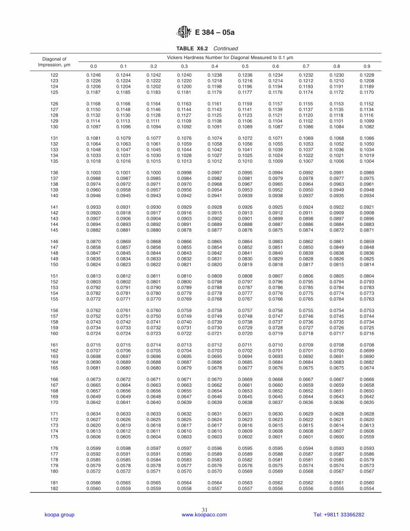
TABLE X6.2 Continued
Diagonal ofImpression, µm
Vickers Hardness Number for Diagonal Measured to 0.1 µm
0.0 0.1 0.2 0.3 0.4 0.5 0.6 0.7 0.8 0.9
122 0.1246 0.1244 0.1242 0.1240 0.1238 0.1236 0.1234 0.1232 0.1230 0.1228123 0.1226 0.1224 0.1222 0.1220 0.1218 0.1216 0.1214 0.1212 0.1210 0.1208124 0.1206 0.1204 0.1202 0.1200 0.1198 0.1196 0.1194 0.1193 0.1191 0.1189125 0.1187 0.1185 0.1183 0.1181 0.1179 0.1177 0.1176 0.1174 0.1172 0.1170
126 0.1168 0.1166 0.1164 0.1163 0.1161 0.1159 0.1157 0.1155 0.1153 0.1152127 0.1150 0.1148 0.1146 0.1144 0.1143 0.1141 0.1139 0.1137 0.1135 0.1134128 0.1132 0.1130 0.1128 0.1127 0.1125 0.1123 0.1121 0.1120 0.1118 0.1116129 0.1114 0.1113 0.1111 0.1109 0.1108 0.1106 0.1104 0.1102 0.1101 0.1099130 0.1097 0.1096 0.1094 0.1092 0.1091 0.1089 0.1087 0.1086 0.1084 0.1082
131 0.1081 0.1079 0.1077 0.1076 0.1074 0.1072 0.1071 0.1069 0.1068 0.1066132 0.1064 0.1063 0.1061 0.1059 0.1058 0.1056 0.1055 0.1053 0.1052 0.1050133 0.1048 0.1047 0.1045 0.1044 0.1042 0.1041 0.1039 0.1037 0.1036 0.1034134 0.1033 0.1031 0.1030 0.1028 0.1027 0.1025 0.1024 0.1022 0.1021 0.1019135 0.1018 0.1016 0.1015 0.1013 0.1012 0.1010 0.1009 0.1007 0.1006 0.1004
136 0.1003 0.1001 0.1000 0.0998 0.0997 0.0995 0.0994 0.0992 0.0991 0.0989137 0.0988 0.0987 0.0985 0.0984 0.0982 0.0981 0.0979 0.0978 0.0977 0.0975138 0.0974 0.0972 0.0971 0.0970 0.0968 0.0967 0.0965 0.0964 0.0963 0.0961139 0.0960 0.0958 0.0957 0.0956 0.0954 0.0953 0.0952 0.0950 0.0949 0.0948140 0.0946 0.0945 0.0943 0.0942 0.0941 0.0939 0.0938 0.0937 0.0935 0.0934
141 0.0933 0.0931 0.0930 0.0929 0.0928 0.0926 0.0925 0.0924 0.0922 0.0921142 0.0920 0.0918 0.0917 0.0916 0.0915 0.0913 0.0912 0.0911 0.0909 0.0908143 0.0907 0.0906 0.0904 0.0903 0.0902 0.0901 0.0899 0.0898 0.0897 0.0896144 0.0894 0.0893 0.0892 0.0891 0.0889 0.0888 0.0887 0.0886 0.0884 0.0883145 0.0882 0.0881 0.0880 0.0878 0.0877 0.0876 0.0875 0.0874 0.0872 0.0871
146 0.0870 0.0869 0.0868 0.0866 0.0865 0.0864 0.0863 0.0862 0.0861 0.0859147 0.0858 0.0857 0.0856 0.0855 0.0854 0.0852 0.0851 0.0850 0.0849 0.0848148 0.0847 0.0845 0.0844 0.0843 0.0842 0.0841 0.0840 0.0839 0.0838 0.0836149 0.0835 0.0834 0.0833 0.0832 0.0831 0.0830 0.0829 0.0828 0.0826 0.0825150 0.0824 0.0823 0.0822 0.0821 0.0820 0.0819 0.0818 0.0817 0.0815 0.0814
151 0.0813 0.0812 0.0811 0.0810 0.0809 0.0808 0.0807 0.0806 0.0805 0.0804152 0.0803 0.0802 0.0801 0.0800 0.0798 0.0797 0.0796 0.0795 0.0794 0.0793153 0.0792 0.0791 0.0790 0.0789 0.0788 0.0787 0.0786 0.0785 0.0784 0.0783154 0.0782 0.0781 0.0780 0.0779 0.0778 0.0777 0.0776 0.0775 0.0774 0.0773155 0.0772 0.0771 0.0770 0.0769 0.0768 0.0767 0.0766 0.0765 0.0764 0.0763
156 0.0762 0.0761 0.0760 0.0759 0.0758 0.0757 0.0756 0.0755 0.0754 0.0753157 0.0752 0.0751 0.0750 0.0749 0.0749 0.0748 0.0747 0.0746 0.0745 0.0744158 0.0743 0.0742 0.0741 0.0740 0.0739 0.0738 0.0737 0.0736 0.0735 0.0734159 0.0734 0.0733 0.0732 0.0731 0.0730 0.0729 0.0728 0.0727 0.0726 0.0725160 0.0724 0.0724 0.0723 0.0722 0.0721 0.0720 0.0719 0.0718 0.0717 0.0716
161 0.0715 0.0715 0.0714 0.0713 0.0712 0.0711 0.0710 0.0709 0.0708 0.0708162 0.0707 0.0706 0.0705 0.0704 0.0703 0.0702 0.0701 0.0701 0.0700 0.0699163 0.0698 0.0697 0.0696 0.0695 0.0695 0.0694 0.0693 0.0692 0.0691 0.0690164 0.0690 0.0689 0.0688 0.0687 0.0686 0.0685 0.0684 0.0684 0.0683 0.0682165 0.0681 0.0680 0.0680 0.0679 0.0678 0.0677 0.0676 0.0675 0.0675 0.0674
166 0.0673 0.0672 0.0671 0.0671 0.0670 0.0669 0.0668 0.0667 0.0667 0.0666167 0.0665 0.0664 0.0663 0.0663 0.0662 0.0661 0.0660 0.0659 0.0659 0.0658168 0.0657 0.0656 0.0656 0.0655 0.0654 0.0653 0.0652 0.0652 0.0651 0.0650169 0.0649 0.0649 0.0648 0.0647 0.0646 0.0645 0.0645 0.0644 0.0643 0.0642170 0.0642 0.0641 0.0640 0.0639 0.0639 0.0638 0.0637 0.0636 0.0636 0.0635
171 0.0634 0.0633 0.0633 0.0632 0.0631 0.0631 0.0630 0.0629 0.0628 0.0628172 0.0627 0.0626 0.0625 0.0625 0.0624 0.0623 0.0623 0.0622 0.0621 0.0620173 0.0620 0.0619 0.0618 0.0617 0.0617 0.0616 0.0615 0.0615 0.0614 0.0613174 0.0613 0.0612 0.0611 0.0610 0.0610 0.0609 0.0608 0.0608 0.0607 0.0606175 0.0606 0.0605 0.0604 0.0603 0.0603 0.0602 0.0601 0.0601 0.0600 0.0559
176 0.0599 0.0598 0.0597 0.0597 0.0596 0.0595 0.0595 0.0594 0.0593 0.0593177 0.0592 0.0591 0.0591 0.0590 0.0589 0.0589 0.0588 0.0587 0.0587 0.0586178 0.0585 0.0585 0.0584 0.0583 0.0583 0.0582 0.0581 0.0581 0.0580 0.0579179 0.0579 0.0578 0.0578 0.0577 0.0576 0.0576 0.0575 0.0574 0.0574 0.0573180 0.0572 0.0572 0.0571 0.0570 0.0570 0.0569 0.0569 0.0568 0.0567 0.0567
181 0.0566 0.0565 0.0565 0.0564 0.0564 0.0563 0.0562 0.0562 0.0561 0.0560182 0.0560 0.0559 0.0559 0.0558 0.0557 0.0557 0.0556 0.0556 0.0555 0.0554
E 384 – 05a
31koopa group www.koopaco.com Tel: +9811 33366282
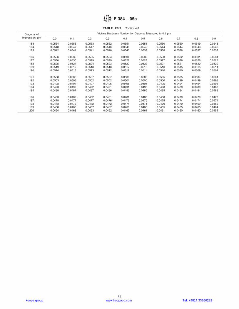
TABLE X6.2 Continued
Diagonal ofImpression, µm
Vickers Hardness Number for Diagonal Measured to 0.1 µm
0.0 0.1 0.2 0.3 0.4 0.5 0.6 0.7 0.8 0.9
183 0.0554 0.0553 0.0553 0.0552 0.0551 0.0551 0.0550 0.0550 0.0549 0.0548184 0.0548 0.0547 0.0547 0.0546 0.0545 0.0545 0.0544 0.0544 0.0543 0.0542185 0.0542 0.0541 0.0541 0.0540 0.0540 0.0539 0.0538 0.0538 0.0537 0.0537
186 0.0536 0.0535 0.0535 0.0534 0.0534 0.0533 0.0533 0.0532 0.0531 0.0531187 0.0530 0.0530 0.0529 0.0529 0.0528 0.0528 0.0527 0.0526 0.0526 0.0525188 0.0525 0.0524 0.0524 0.0523 0.0522 0.0522 0.0521 0.0521 0.0520 0.0520189 0.0519 0.0519 0.0518 0.0518 0.0517 0.0516 0.0516 0.0515 0.0515 0.0514190 0.0514 0.0513 0.0513 0.0512 0.0512 0.0511 0.0510 0.0510 0.0509 0.0509
191 0.0508 0.0508 0.0507 0.0507 0.0506 0.0506 0.0505 0.0505 0.0504 0.0504192 0.0503 0.0503 0.0502 0.0502 0.0501 0.0500 0.0500 0.0499 0.0499 0.0498193 0.0498 0.0497 0.0497 0.0496 0.0496 0.0495 0.0495 0.0494 0.0494 0.0493194 0.0493 0.0492 0.0492 0.0491 0.0491 0.0490 0.0490 0.0489 0.0489 0.0488195 0.0488 0.0487 0.0487 0.0486 0.0486 0.0485 0.0485 0.0484 0.0484 0.0483
196 0.0483 0.0482 0.0482 0.0481 0.0481 0.0480 0.0480 0.0479 0.0479 0.0478197 0.0478 0.0477 0.0477 0.0476 0.0476 0.0475 0.0475 0.0474 0.0474 0.0474198 0.0473 0.0473 0.0472 0.0472 0.0471 0.0471 0.0470 0.0470 0.0469 0.0469199 0.0468 0.0468 0.0467 0.0467 0.0466 0.0466 0.0465 0.0465 0.0465 0.0464200 0.0464 0.0463 0.0463 0.0462 0.0462 0.0461 0.0461 0.0460 0.0460 0.0459
E 384 – 05a
32koopa group www.koopaco.com Tel: +9811 33366282
X7. REVISIONS
X7.1 New sections 10.8.5 through 10.8.8.
X7.2 New Annex A1.
X7.3 New Appendix X4.
REFERENCES
(1) Campbell, R.F., et al., “A New Design of Microhardness Tester andSome Factors Affecting the Diamond Pyramid Hardness Number atLight Loads,” Trans. ASM, Vol 40, 1948, pp. 954-982.
(2) Kennedy, R.G., and Marrotte, N.W., “The Effect of Vibration onMicrohardness Testing,” Materials Research and Standards, Vol 9,November 1969, pp. 18-23.
(3) Brown, A.R.G., and Ineson, E., “Experimental Survey of Low-LoadHardness Testing Instruments,” Journal of the Iron and Steel Inst., Vol169, 1951, pp. 376-388.
(4) Thibault, N.W., and Nyquist, H.L., “The Measured Knoop Hardness ofHard Substances and Factors Affecting Its Determination,” Trans.ASM, Vol 38, 1947, pp. 271-330.
(5) Tarasov, L.P., and Thibault, N.W., “Determination of Knoop HardnessNumbers Independent of Load,” Trans. ASM, Vol 38, 1947, pp.331-353.
(6) Vander Voort, G.P., “Results of an ASTM E04 Round Robin on thePrecision and Bias of Measurements of Microindentation Hardness,”Factors that Affect the Precision of Mechanical Tests, ASTM STP 1025,ASTM, Philadelphia, 1989, pp. 3-39.
(7) Vander Voort, G.F., “Operator Errors In the Measurement of Microin-dentation Hardness,” Accreditation Practices for Inspections, Tests,and Laboratories, ASTM STP 1057, ASTM, Philadelphia, 1989, pp.47-77.
ASTM International takes no position respecting the validity of any patent rights asserted in connection with any item mentionedin this standard. Users of this standard are expressly advised that determination of the validity of any such patent rights, and the riskof infringement of such rights, are entirely their own responsibility.
This standard is subject to revision at any time by the responsible technical committee and must be reviewed every five years andif not revised, either reapproved or withdrawn. Your comments are invited either for revision of this standard or for additional standardsand should be addressed to ASTM International Headquarters. Your comments will receive careful consideration at a meeting of theresponsible technical committee, which you may attend. If you feel that your comments have not received a fair hearing you shouldmake your views known to the ASTM Committee on Standards, at the address shown below.
This standard is copyrighted by ASTM International, 100 Barr Harbor Drive, PO Box C700, West Conshohocken, PA 19428-2959,United States. Individual reprints (single or multiple copies) of this standard may be obtained by contacting ASTM at the aboveaddress or at 610-832-9585 (phone), 610-832-9555 (fax), or [email protected] (e-mail); or through the ASTM website(www.astm.org).
E 384 – 05a
33koopa group www.koopaco.com Tel: +9811 33366282