second conceptual structures tool interoperability...
TRANSCRIPT

Second ConceptualStructures Tool
Interoperability Workshop
In Association With
Heather D. Pfeiffer, Adil Kabbaj, David Benn (Eds.)
Research Press International

Second Conceptual Structures Tool Interoperability Workshop Sheffield, UK
2007
Permission to make digital or hard copies of all or part of this work for personal or classroom use is granted without fee provided that copies are not made or distributed for profit or commercial advantage and that copies bear this notice and the full citation on the first page. To copy otherwise, to republish, to post on servers or to redistribute to lists, requires prior specific permission.
© 2007 Heather D. Pfeiffer, Adil Kabbaj, David Benn (Eds.)
ISBN: 1-897851-16-2
Heather D. Pfeiffer NMSU, Department of Computer Science,
PO Box 30001/MSC CS Las Cruces, NM, USA 88003-8001
email: [email protected]
Adil Kabbaj INSEA, BP: 6217, CP: 10100, Rabat, Morocco
email: [email protected]
David Benn 73 Second Avenue,
Klemzig, South Australia, 5087 email: [email protected]
Published by Research Press International
PO Box 144, Bristol, BS9 1YA, UK Tel: (44) 0117 9685039
Research Press International is a division of αlpha Books (Stoke Bishop)

Preface
As discussed last year, many tools have been developed in the Conceptual Structurescommunity to model, represent and reason over different conceptual structures. Theseinclude formalisms included but not limited to Conceptual Graphs, Formal ConceptAnalysis, and Topic Maps. However, these tools mainly work in isolation and arenot sufficient to build comprehensive, collaborative and effective knowledge systemsuseful to the community. To this purpose, this workshop is exploring how these toolscan be able to interoperate between themselves and other information technologies.
The ICCS Conceptual Structures Tool Interoperability workshop (CS-TIW 2007)was organized to continue to focus on the three main themes from CS-TIW 2006:
Interoperability Requirements
What types of applications do conceptual structures tools have in real world knowl-edge systems and systems development methodologies? What requirements do theseapplications impose on conceptual structures tools? What breakdowns occur in actualapplication practice? What (ad hoc or more systematic) solutions have been developedto deal with these problems?
Knowledge Systems Architectures
What components do effective knowledge systems have? What is the role of conceptualstructures tools in these systems? How to conceptualize knowledge systems interop-erability in terms of standard information systems and software engineering method-ologies? What architectural principles should guide knowledge systems design andimplementation?
Interoperability Standards
What are the most relevant official and de facto standards affecting conceptual struc-tures tool interoperability? How should these standards influence knowledge systemsdesign? How to evaluate the standards in a practical knowledge system implemen-tation? How can practical interoperability experiences inform the standards settingprocess?
We received some very diverse approaches to interoperability from our paper contribu-tions. Each paper was reviewed by at least two of the chair persons (some all three).Then we attempted to choose from these contributions the approaches that would pro-mote the most discussion by being presented at the workshop.
Our keynote speaker, Aldo de Moor, will be presenting an approach for pragmaticevaluation of tool system interoperability. The main elements in this approach are aconceptualization of the tool system in its usage context and in its evaluation process.With these basic elements, pragmatic evaluation can be operationalized in many differ-ent ways, with development focus on the technical and semantic aspects of tool systeminteroperability.
i

The invite paper is followed by six papers from leading researchers in the concep-tual structures tools building community evaluating and addressing a wide range oftheoretical and practical approaches that relate to the workshop themes.
Achieving conceptual structures tool interoperability is essential for building col-laborative tool systems that can work with information systems in the real world. Wehope that this workshop will continue to focus research and development of tools thatcan address this important topic even more fully in France at ICCS 2008.
July 2007
Heather D. PfeifferAdil KabbajDavid Benn
ii

Table of Contents
Invited Paper
The Pragmatic Evaluation of Tool System Interoperability ........................ 1
Aldo de Moor
Contributed Papers
Visualisation of Semantic Content and Interoperability ............................ 21
Pavlin Dobrev, Galia Angelova
The Extent to Which Interoperability Between CG and Non CG
Tools Can be Assessed Against the Semiotic Ladder ................................. 35
Peter Maybery and Simon Polovina
Using interoperating conceptual tools to improve searches
in Kaj Munk .............................................................................................. 45
Ulrik Petersen
Adding Conceptual SIGNs to a Computer Memory Resident
Data Structure Based on the Phaneron of C.S. Peirce .............................. 57
Jane Campbell Mazzagatti
Interoperability: The next steps for Amine Platform ................................ 65
Adil Kabbaj
CPE Design Considering Interoperability ................................................. 71
Heather D. Pfei�er, Nemecio R. Chavez, Jr., Joseph J. Pfei�er, Jr.
iii

iv

The Pragmatic Evaluation of Tool SystemInteroperability
Aldo de Moor
CommunitySenseCavaleriestraat 2, 5017 ET Tilburg, the Netherlands
Abstract. Collaborative communities are increasingly supported by systems ofinformation and communication tools. Much current research and developmentfocuses on the technical and semantic aspects of tool system interoperability.However, for developing effective tool systems, their pragmatic evaluation is alsoessential. This implies that the usage context of tools is taken into account. In thispaper, we envision an approach to the pragmatic evaluation of tool system inter-operability. Its main elements are a conceptualization of the tool system, its usagecontext, and an evaluation processs. With these basic elements, pragmatic evalu-ation can be operationalized in many different ways. We illustrate our approachwith several real-world examples.
1 Introduction
Information systems development in the classic sense of waterfall-based requirementsanalysis, design, and implementation of monolithic and customized information sys-tems more or less from scratch is on the way out. Collaborative communities, in whichpeople work together to accomplish common goals, increasingly make use of a widerange of (Internet-based) information and communication tools to support their infor-mation processing, communication, and coordination needs. A typical configuration forsuch a community includes a content management system, a couple of mailing lists, dis-cussion fora, chat or conferencing software, co-authoring tools, a calendar tool, and soon. However, this is only a minimal set of tools. Most communities use a wide range ofadditional tools, very much depending on the particular domain they are in1.
We define a tool system as the set of integrated and customized information andcommunication tools tailored to the specific information, communication, and coordi-nation requirements of a collaborative community. There are numerous, partially over-lapping implementations of such functionalities. In addition, many of these tools arebuilt on top of an emerging cyberinfrastructure of organizational practices, technical in-frastructure, and social norms [14]. Furthermore, each community has its own, uniqueway of using these functionalities. Finally, the requirements and technologies used are
1 A very good example are disaster response communities. One domain-specific tool that hasproven its worth is the Sahana open source disaster management system, which was developedin Sri Lanka after the 2004 tsunami: http://www.sahana.lk
1

in constant flux. In all, this makes it extremely complicated to come up with standard-ized prescriptions for the best tool system for a particular community at a particularmoment in time. New forms of analysis, roles in software development, and the mean-ing of use and maintenance need to evolve [28]. To design useful information systemsby selecting the right components, available functionalities in the form of modules andservices need to be evaluated in their context of use by the communities of use them-selves.
A tool system is all about synergy and alignment. How to create a well-tuned or-chestra out of these tools, which is able to perform a magnificent symphony? Like ina human orchestra, this should go much beyond listing a set of the technical abilitiesof the orchestra members. Each member has her own strengths and subtleties, whichcannot be exactly described, but needs to be experienced. Then, after much practiceand trial-and-error, the ensemble of all these unique individuals starts to express yet an-other layer of synergetic qualities, distinct for different pieces played. Everybody wouldagree that to assess the strengths and weaknesses of the various orchestra members, toknow which pieces they are best able to play, and to create the right combination of per-formers, the trained ear of an experienced conductor is indispensable. Yet, in the designof tailored tool systems, arguably similarly complex, the conductor is missing.
In systems development for collaborative communities, the real difficulty is not indescribing the functionalities of the individual tools, but in assessing the interoperabilityof a configuration of tools in a particular usage context. Much has been said aboutinteroperability. The most general definition is that interoperability is the need to makeheterogeneous information systems work in the networked world [33]. One that is bettersuited for our purpose of the assessment of tool system interoperability is the one givenby Miller in [24], who defines it as the ongoing process of ensuring that the systems,procedures, and culture of an organisation are managed in such a way as to maximiseopportunities for exchange and re-use of information, whether internally or externally.In such a view of interoperability, finding a way to represent and analyze the usagecontext is all-important.
Much interoperability research stems from the domain of component-based systemsdevelopment and web services. The importance of syntactic and semantic interoperabil-ity has been recognized for quite a while already [29, 17]. For example, the UniversalDescription, Discovery and Integration (UDDI) standard provides rules for building ser-vice directories and the facilitation of top-down querying capabilities [34]. However, al-though syntactic and semantic interoperability is necessary, also the context-dependent(i.e. pragmatic) needs of the users should be taken into account by more explicitly link-ing service description, discovery, and invocation to context [30].
The key questions we will address in this paper are the following: how to conceptu-alize the idea of usage context in tool system interoperability evaluation? What wouldan evaluation procedure look like? What would the results of such a procedure be interms of design choices? The goal of the paper is to come up with a ”minimal con-ceptual model”, an ontology as it were of the main concepts and relations needed todevelop pragmatic evaluation methods. Such a model can be used in the constructionof actual methods tailored to the specific needs of real-world user communities. It can
2

be used as a framework for the construction and comparison of such methods, ensuringthat they are truly pragmatic in the semiotic sense of the word.
In this paper, we will synthesize and extend a body of recent work. In [8], we ex-amined the role of pragmatic patterns in the evolution of semantic resources. In [7],we presented a basic conceptual model of tool system interoperability. We proposeda practical community-driven courseware evaluation approach in [10]. Together, thesebuilding blocks are the foundation of the pragmatic evaluation approach proposed inthis paper.
In Sect. 2, we give an informal introduction into the kind of issues at play in prag-matic tool system interoperability by exploring a real-world example of a tool systemused to support the co-authoring of a call for papers. In Sect. 3, we conceptualize thetool system. Sect. 4 captures the usage context. In Sect. 5, we model the evaluationprocess. We end the paper with a discussion and conclusions in Sect. 6 and 7.
2 Pragmatic Tool System Interoperability Evaluation in Practice:Co-Authoring a Call for Papers
Community interaction processes tend to be very complex, leading to context-specificrequirements which often cannot be met completely by any particular tool. Vice versa,many tools are often used for a very different purpose than what they were originallydesigned for. Thus, the tool systems emerging to support collaboration are about theprocess of articulating ways how to use the tools as much as about the functionalitiesthemselves, if not more so. Next, we will describe a powerful real-world example ofhow relatively straightforward tools can be combined into tool systems that as a wholeprovide very complex but useful functionality2.
In 2006, the author was one of the three co-chairs of the First International Prag-matic Web Conference. Since the chairs live and work far apart, they tried to write theCall for Papers by sending Word-files around. However, as the Pragmatic Web is sucha new paradigm, confusion abounded and versions kept flying back and forth betweenthe three of them. It was clear that just using e-mail and word processors did not fit theircollaborative needs.
The co-chairs, additionally, had a need for voice contact. However, the phone wouldnot do, since the three of them needed to discuss simultaneously. Phone conferenceswere still relatively expensive, so they decided to use Skype instead. This voice-over-Internet application at the time allowed up to five people to discuss for free. Additionalbenefits were that the sound quality is much better than that of the phone, and that onecan talk using a microphone. This means that one’s hands are free and one can typewhile talking.
Although the co-chairs could now talk simultaneously, they were not there yet. Theywere considering three versions of the document: one previously written by one chair,one by another chair, and the third one the version-in-progress which contained themodifications that they were making as they spoke. This was too much, as all of themwere getting very confused by all those almost-but-not-quite similar texts. Instead, theycame up with the following solution (Fig. 1).
2 Previously described on http://growingpains.blogs.com/home/2006/03/it takes at lea.html
3

Fig. 1. A Tool System for Co-Authoring a Call for Papers
– All co-chairs opened one of the previous versions in Word for reference.– One co-chair acted as editor, and opened the version of the second chair as the
starting point of the version-in-progress.– The co-chairs started editing this version paragraph-by-paragraph, line-by-line. Each
time, the editor would copy the paragraph currently being discussed, and paste itinto Skype’s chat-window.
– All three co-chairs would look at this paragraph, and compare it with the sameparagraph in the other Word-version. They could then propose and discuss modifi-cations a few lines at a time. The editor kept track of these changes in the versionbeing edited. Having agreed orally upon only a few lines, it was already getting dif-ficult to see the bigger picture. Whenever that was the case, the editor copy/pastedthe now modified paragraph into Skype-chat again. The co-chairs would then -orally - make a few more changes, to be copy/pasted into Chat by the editor.
– This continued until all co-chairs were satisfied with the full paragraph. They thenmoved on to the next paragraph, until they were, at last, happy with the final Callfor Papers.
So, what exactly happened? A few standard tool functionality components wereused: Word for editing text; Skype-Conference for group voice discussion; Skype-Chat for keeping track of the rapidly changing ”focus-text”. Two roles (Author, Edi-tor) were distinguished. A few simple process rules were adhered to: all authors focuson the same paragraph; all authors compare the current focus-paragraph with the re-lated Word-paragraph and make comments; the editor changes lines on which consen-sus has been reached in the version-in-progress; the editor pastes modified paragraphsinto chat whenever there is too much confusion. This arrangement then allowed for a
4

very complex group authoring process to be successfully supported by information andcommnunication technologies. For all the co-chairs, it has been a transformative expe-rience to see how such a dauntingly complex collaborative task could be done onlineinstead of face-to-face. This experience reconfirms the idea that the future of collabora-tion support will not be in very expensive, proprietary collaborative platforms. Instead,continuously rediscovering the right combination of tools, process, and context seemsto be the direction to go.
3 A Conceptual Model of the Tool System
A functionality is a set of functions and their specified properties that satisfy stated orimplied needs3. Functionalities come in different forms of aggregation, from simpleword processing functions to complete modules and applications supporting particu-lar workflows or business processes. When evaluating functionality, the right level ofgranularity should be chosen.
In [7], we introduced a basic model of a tool system, consisting of components ofdifferent levels of granularity. At the lowest level of granularity, we distinguish systemsof tools or services. The next level consists of the tools or services themselves. Thencome the modules comprising the tools or services. Finally, we distinguish the particularfunctions grouped in a module.
Fig. 2. A Functionality Decomposition of the Co-Authoring Tool System
3 Definition by the Software Engineering Insitute Open Systems Glossary:http://www.sei.cmu.edu/opensystems/glossary.html
5

Functionality components of different levels of granularity can be linked in manyways. The interface between two functionality components A and B is described by theexternally visible representation of the knowledge structures used in A and B.
In [7], we focused on the communication aspects of the interoperating functionalitycomponents. We abstracted from the internal information processes, which are oper-ations on information objects within a functionality component, such as the creation,modification, or deletion of an object. For tool selection, such processes are important,however, so we include them in our conceptual model. Note that we are only inter-ested in those information processes visible to a user, so we abstract from all internalcomputational processes.
Fig. 2 gives a functionality decomposition of the main elements of the co-authoringsupport system described in the previous section. For simplicity, information objectsand processes have not been included. The Skype Conference-module includes thefunction that allows a group of users to discuss. Its Chat-module allows users to typetext, paste text from the clipboard onto the chat screen, and to view the typed and pastedtext. One of the main modules of Word is to support the processing of text, includingediting a text file and copying text onto the clipboard.
Strictly speaking, a tool system conceptualization is only about functionality, notabout context. However, the tools, modules, and functions selected are a subset of all po-tentially available functionality. This selection is determined by the usage context. Thisis a good example of how the Tool System and the Human System are co-dependentand co-evolve, to use Doug Engelbart’s terms [15].
This leads us to the question how to conceptualize the usage context? It is clear thata sense of communal purpose is important, but how exactly to operationalize this notionand its linkages to the tool system?
4 A Conceptual Model of the Usage Context
In [8], we made a first stab at modelling the pragmatic layer of web-based informationsystems. We claimed that there needs to be a user-controlled selection process of seman-tic representations4. We defined a pragmatic context to consist of a common context anda set of individual contexts. The common context was defined by the common conceptsand conceptual definitions of interest to a community, the communicative interactionsin which these concepts are defined and used, and a set of common context parameters(relevant properties of concepts describing the context). Each community member wassaid to have an individual context, consisting of individual concepts and definitions ofinterest, as well as individual context parameters. We then characterized the pragmaticcontext by a set of pragmatic patterns, including individual and common pragmatic pat-terns. In that paper, we focused on the meaning negotiation process between communitymembers and did not further explore the notion of the common and individual contextparameters, nor their conceptualization in patterns. In the current paper, the focus is
4 Although in the current paper, the focus is on functionality selection rather than semanticsresources selection, this distinction is not relevant here. In both cases, we are interested in theontological status of resources/tools, and how their relevance to communities of users can beassessed.
6

reversed: we do not so much look at how individual and common pragmatic patternsinfluence the meaning negotiation process. Rather, we further explore the make-up ofthe individual and common pragmatic patterns, and how they come about in the firstplace. In that sense, the papers complement each other.
4.1 Goals
Goals or objectives are crucial in the pragmatic view. Everything starts with goals. Goalsgive a sense of purpose, drive people and processes, and can be used as evaluationcriteria.
We distinguish two types of goals. First, there are activities, such as “writing acall” or “making a group assigment”. Such activities in fact are operationalized goals:processes with a concrete deliverable as an outcome, often in the form of an informa-tion object such as a report or a message. However, many goals are abstract and cutright across processes and structures. Examples of such goals are non-functional re-quirements and quality criteria, like ”security”, ”interactivity”, and so on. We call suchabstract goals aspects.
Although activities can be viewed as workflows, we abstract from their design andimplementation details, such as concurrency and sequence. Although definitely impor-tant in the final construction of the information system, for the purpose of functionalitycomponent selection they add unnecessary complexity. This initial stage, the focus ofthis paper, concerns itself much more with selection of potential functionalities, nottheir actual configurations for workflow support.
4.2 Actors
Many stakeholders are involved in tool system evaluation. For example, in the domainof courseware evaluation, students, teachers, the computer center, etc. all have their veryspecific, often partially incompatible interests, needs, and goals. Students prefer easy-to-use functionalities, whereas main concerns of the computer center include securityand reusability [10]. In order to ensure that all requirements are captured, contrasted,and balanced, it is not sufficient to examine ”The User”. Instead, a very careful inven-tory needs to be made of the actor roles that the various stakeholders play. Makingroles explicit is gaining prominence in, for instance, the Role Based Access Controlparadigm5 as a way to systematically determine actor responsibilities in workflows andaccess to functionalities and information resources. Most role classifications are quiteabstract and technology-focused (Administrator, Facilitator, Member etc.). However,many other typologies are possible, often quite specific to a particular domain. Rolescould, for instance, be based on workflow process (Author, Editor, Reviewer, ...), or-ganizational structure (Secretary, Manager, ...), or based on the main stakeholders in aparticular domain (UNEP, Corporation, NGO, ...). Carefully defining the responsibili-ties, permissions, and prohibitions attached to these roles helps in better definining theuse patterns of information systems. Besides operational status, such actor roles shouldalso be explicitly involved in the development of the socio-technical systems-in-use, asis the focus of this paper
5 http://csrc.nist.gov/rbac/
7

4.3 Domain
A third layer of the model is the domain in which the collaborative community usingthe tool system (inter)operates. The domain is an important, but still ill-understood el-ement in tool system evaluation. Aspects that influence evaluation processes and func-tionalities of the tool system include issues of structure and size, for example is it adistributed network or centralized organization, a large or a small organization? Whatsetting is the tool being used in: an academic, a corporate, a governmental, or a non-governmental setting? What is the financial situation: are there resources for acquisitionor customization of software, or is off-the-shelf, open source software the only option?Are there political alliances and commitments that force or preclude the use of certainsoftware? In other words, the domain determines how many degrees of freedom thereare in evaluation process.
5 The Tool System Interoperability Evaluation Process
Summing up, we have established tool functionality components, goals (activities andcriteria), actor roles played by users, and the domain as important primitives playing arole in the evaluation process of tool system interoperability (Fig. 3). We now examinethe structure of this process itself.
The stakeholders playing actor roles are usually very busy, and have little time andopportunity to develop an in-depth knowledge of the technology at hand nor to makemany requirements explicit. Each human stakeholder possesses a treasure trove of sub-tle tacit knowledge of the tool system-in-use. Tacit knowledge is highly personal and isdeeply rooted in action, procedures, routines, commitment, ideals, values and emotions,and is thus hard to formalize [20]. Creating massive, unwieldy evaluation processesforcing users to assess numerous issues in detail is a dead-end road. Rather, a usefulmethod should focus on a few, comprehensive goals, which allow for commonalitiesand differences in evaluations to be easily established, while giving ample opportunityfor efficiently zooming in on the underlying factors in human discussion processes.The core goals could thus be used as a sieve, allowing expensive human interactionsto be focused immediately on the most interesting issues of shared understanding anddisagreement.
Although the number of evaluation goals to be made explicit should be minimized,a well-structured evaluation process is needed, respecting the different perspectives ofthe stakeholders. The reasons for making final selection decisions need to be clearlyconveyed to the users to increase legitimacy and technology acceptance. Decisions onfunctionality component selection and configuration should be devolved to the lowestactor-level possible. For example, in a courseware setting, overall class functionalitychoices will generally need to be made by the lecturer, group settings by the groups,and individual settings by the individual user.
5.1 Evaluation Subprocesses
To structure the evaluation process, we subdivide it into three subprocesses: use, inter-pretation, and decision making.
8

Fig. 3. The Pragmatic Tool System Interoperability Evaluation Process
– In the use process, users get hands-on experience with the functionalities. Evalua-tions can be either ex-ante or ex-post this use process. Ex-ante evaluations may in-volve scenarios: task-based expressions of human-machine interaction, which helpusers to at least partially imagine the potential usefulness and acceptability of func-tionalities [32]. Ex-post evaluations concern evaluations done after the functionalityhas been actually used. Although ex-ante evaluations can be useful, ex-post evalua-tions are preferred, since unexpected affordances and constraints of functionalitiesoften only become apparent during actual use [37].
– The interpretation process is the process in which the users score and then use thescores to prioritize and discuss the usefulness of the tool system (as there are manyways to obtain scores, and as the scoring process is the most formal and quantitativestage of the interpretation process, it will be further discussed in Sect. 5.2). It is cru-cial that the interpretation process is both effective and efficient. The interpretationprocess needs to be effective, in that - ideally - the interests and goals of all relevantstakeholders are satisfied. This requires that the right stakeholders are involved inthe evaluation, and that they are provided with an instrument to actively identify,compare, and discuss their requirements and interests. Carefully designed strategies
9

are needed to balance the often competing demands of many different stakehold-ers [2]. The evaluation process should also be efficient. Empirical findings haveshown that users have more confidence in simple information and communicationtechnology (ICT) evaluation methods [5]. If evaluations become more numerous,and are to be performed by very busy professionals who often have other priori-ties, only the most relevant questions should be asked. This could be done in theform of an initial quick-scan, with more detailed analysis of areas identified to beproblematic only to be done in a follow-up analysis. Evaluation criteria need tobe defined, which in our case are determined by the goals (activities as well as as-pects). These criteria can range from simple activities to be supported to abstractaspects like usability. Evaluation criteria should on the one hand be understandableby the user; on the other hand be precise and comprehensive enough to capturethe complexity of the tool system development and use. Second, the communitydoing the evaluation needs to be characterized: What are the actors and their goalconcepts? Does the community evaluate as a whole, arriving at a single, majorityor consensus evaluation result, or is it decomposed into groups or even individuals.How do their differences in evaluations play a role in the interpretation and decisionmaking processes?
– Finally, decision making needs to take place based on the evaluation results. Thedecision making process needs to be examined from the point of view of stake-holders involved, the decision making procedure, and types of interventions in thesocio-technical system. Who makes the decisions on the tool system design andimplementation: the users and interpreters, or external authorities? Is the decisionmaking procedure based on quantitative results only, or are also qualitative descrip-tions taken into account? Is there any interaction between interpreters and decisionmakers? How are the results used to decide on the selection/acquisition, configura-tion, or integration of new software?
5.2 The Scoring Process
The subprocesses sketched above can be implemented in many different ways. We donot aim to provide one particular approach here, since our goal is really to sketch theframework in which to position these processes. However, we will examine one crucialsubprocess, the scoring process, in more depth here, as it is at the heart of the inter-pretation process. This, in turn, is the main process in which stakeholders reflect on theroles of the various technologies in their complex usage context.
In [10], we presented a scoring method based on Bedell’s method for the evaluationof IT functionality effectiveness [4]. In Bedell’s method, IS functionalities are scoredon both the effectiveness and importance for the activities they support. The activitiesthemselves are also scored on their importance to the organization. The importancescores act as weights for the effectiveness scores. Bedell has developed a whole rangeof increasingly aggregate indicators, the most general one being whether as an organi-zation to invest in ICT at all. Through these indicators, the method is a useful aid in theorganizational ICT interpretation and decision making process.
Simplifying Bedell’s approach, we proposed a practical method for coursewareevaluation in [10]. This approach is applicable to any tool system, however. Rather
10

than using Bedell’s elaborate and quite complex framework of indicators, we limitedourselves to two indicators: activity scores and functionality scores. These indicatorscan be used to answer two basic questions: (1) how well are the various activities sup-ported by the functionality components? (2) how effectively are the various functional-ity components used? In the current paper, we keep the notion of functionality scores,but generalize the activity scores to goal scores, as not only activities but also cross-activity aspects are possible sources of purpose to be taken into account in evaluation.We therefore consider both activity scores and aspect scores to be subtypes of goalscores.
Goal Scores
Goal (activity/aspect) scores show how useful the combined functionality compo-nents are for the support of a particular goal. Functionality scores represent the use-fulness of a particular functionality component in supporting the combined goals of acommunity. In calculating these scores, the basic elements to be defined by the users intheir actor roles are:
Fig. 4. Activity Scores for Blackboard and CourseFlow in 2003
– I(g) = importance of a goal– I(f, g) = importance of a functionality in supporting a particular goal– Q(f, g) = quality of a functionality in supporting a particular goal.
Users can define their own criteria for explicating the importance and quality scores,or leave them implicit, just using their intuition. Whether they decide to further explicatetheir assessments or not, our approach allows (individual) evaluations to be positionedand aggregated in the larger evaluation framework and process.
(i) G-Score =∑
I(fi, g) ∗ Q(fi, g), for all functionalities 1..i
For all functionality components fi supporting a particular goal g, the experiencedquality of the support they provide, is multiplied by their importance in supporting this
11

activity. The sum of these values measures the usefulness of the combined tool com-ponents for a particular goal to the scoring user. This measure is especially useful fortechnology users, such as lecturers and students, or program chairs.
(ii) F-Score =∑
I(gj) ∗ I(f, gj) ∗ Q(f, gj), for all goals 1..j
For all goals gj supported by a particular functionality component f , the qualityof the support provided is multiplied by its importance for this activity and by the im-portance of the goal. This last multiplication is necessary as support for goals moreimportant to the users should weigh more than for less relevant goals. The sum of thesevalues measures the usefulness of a particular functionality component for the com-bined goals of the scoring user(s). This measure is especially useful for technologymaintainers and developers. It allows, for example, a university computer centre or cor-porate IT department to determine which tool system components to get, or to get ridof.
An Example: Evaluating the Making of Group Assignments with Courseware
In 2002 and 2003, the approach was experimented with by Information Manage-ment students at Tilburg University. In both years, they tested the value of differentBlackboard modules for the making of group assignments. This process was subdividedinto four activities (information collection, group discussion, submission of results, andfeedback from peers), while 11 functionality modules were examined (Send E-Mail,Discussion Board, Virtual Chat, etc.). In 2003, also an open source courseware tool,CourseFlow, was scored on similar modules. The results were interpreted by the soft-ware manager of Tilburg University, who considered them useful as an input in futuredecision making for courseware acquisition.
In this paper, we are not going in depth into the details of the scoring process. A de-tailed account of the goals, design, and results of the experiment is given in [10]. Fromthat paper, we show two figures to give the reader a feel for how the process works.Fig. 4 shows how similar both tools are in their support for group assignment making.Fig. 5 shows how similar both tools in the experienced usefulness of their functionalitycomponents. This is powerful evidence for the usefulness of open source courseware,at least from the point of view of students. Given that much open source software isactually more reliable and secure than proprietary software, from the point of view ofthe computer center as well, open source courseware could be a viable alternative to ex-pensive vendor software. By making careful evaluations of which activities need to besupported by which particular functionalities, the funds then becoming available mightbe put to much better use, for example to develop functionality for needs that currentlyare not supported. To give an indication, Tilburg University alone, with about 10,000students, paid many tens of thousands of euros in license fees for the use of Blackboardcourseware in 2003. Given the strong collaboration of Dutch universities in the inter-university ICT and networking organization SURFNet, the combined funds for a jointcourseware product development and evaluation project might easily add up to manyhundreds of thousands of euros annually. Many universities already have an installedbase of (proprietary) courseware applications. It is not feasible to completely change
12

Fig. 5. Functionality Scores for Blackboard and CourseFlow in 2003
applications. However, through plug-ins and links, specialized functionality modulescan be easily added to applications. Courseware evaluation of components should con-tribute to detect the gaps which such specialized modules could fill.
Our approach only provides a bird’s eye view. Very high scores indicate high qualityand high importance; very low scores indicate low quality and low importance. To in-terpret intermediate results correctly, the source data need to be analyzed in more detail,and to ensure the significance of many of the smaller differences, statistical tests such ast-test comparisons would be needed . However, given the complexity of the evaluationtask, and the many different opinions of what are relevant evaluation criteria, false pre-cision would not add much value. Instead, recognition of the broad patterns as a startingpoint for focused discussion and analysis is what a method like ours can contribute
The particular results may not be completely generalizable to other student popu-lations, as Information Management students may have different preferences and eval-uation criteria given their personal interest in advanced information technologies. Fur-thermore, courseware may also be used for many different purposes. In this paper, weanalyzed only the group assignment handling process, but scores are probably very dif-ferent when the method is applied to other workflows.
6 Discussion
Besides being limited in scope with respect to results, the scoring process proposed isstill primitive in methodological functionality. Possible extensions include user-friendlyversions of Bedell’s [4] more advanced concepts, allowing for more refined judgmentsin the intermediate range of scores. Besides just giving a generic quality score, specific
13

quality aspects such as user friendliness, effectiveness, and maintainability could be in-cluded. Such indicators themselves also need to be interlinked, for example to ensurethat different indicators measure the same quality aspect, thus increasing the value ofmeasurement [35]. However, we should be careful not to introduce too much method-ological complexity, as it scares away intended users and makes interpretation of eval-uation results by the users themselves difficult. Careful consideration of the trade-offbetween methodological power and comprehensibility, for example by experimentationwith different types of scores and visualizations, might considerably increase the valueof a practical evaluation method (e.g. [16]).
Another limitation of the example approach presented is that only students wereasked to evaluate courseware functionality. Still, their aggregated evaluations were usedin decision making by other stakeholders, such as the software manager. A more com-prehensive approach thus would have to contrast evaluations by different stakeholders,since the interests of all stakeholders need to be balanced. For example, what is the soft-ware manager to do when a lecturer evaluates a functionality shared with students verydifferently? Whose evaluation to give preference? To address these important issues,techniques to identify and manage stakeholders interests, and to design high-qualitymulti-stakeholder dialogues aimed at improved relationship building and learning po-tentials could play a key role [2, 23].
The IS quality literature has produced many evaluation criteria frameworks, cover-ing more or less completely the information systems development process. One classicexample is Delen and Rijsenbrij’s quality tree, which decomposes information systemsquality into 46 quality attributes, organized in four dimensions: the process dimension,concerning the development process; the static dimension, which refers to the control ofthe IS; the dynamic dimension, covering the functioning of the system as perceived bythe user; and the information dimension, concerning the quality of the information itself[11]. Along similar lines, DeLone and McLean, in their famous survey article of the lit-erature, identified a very large, confusing and partially overlapping set of IS ”success”measures [12]. Whereas business process models and workflow patterns can extend theontologies of activity-type goals in our evaluation approach, such quality frameworkscan do the same for the aspect-type goals.
The weighing, comparison, and aggregation of scores is more complex than sketchedhere: for example, there are many dependencies between goals. Also, can activities andaspects be compared in one measure, or should they be measured separately? To re-fine such aspects, pragmatic evaluation could also benefit from the quality IS litera-ture. Many evaluation methods have been designed, so many that their classificationhas become a research topic in its own. For example, based on whether an evaluationmethod has a financial or non-financial focus and the type of parameter calculationtechnique used, Renkema and Berghout distinguish between financial, multi-criteria,ratio, and portfolio approaches [26]. Typical examples of financial methods are calcu-lations of Net Present Value and Internal Rate of Return. However, since just focusingon financial aspects is insufficient when looking at information systems with strategicimpact, some explicit process needs to be designed to make intangibles measurable aswell [19]. Multi-criteria approaches allow for non-financial aspects to be quantified,preferably leading to aggregate measures for each investment. For example, in their In-
14

formation Economics method, Parker et al. distinguish between different non-financialaspects from the business and technology domains, such as ’strategic match’ and ’ISinfrastructure risk’ [22]. These aspects get weighed and scored, leading to subtotals ofpositive and negative weighted scores, which give an indication of the overall value ofthe proposal. Related methods like Quality Function Deployment (QFD) help to trans-late customer needs into balanced sets of relevant design and production requirements[6].
A different classification of evaluation methods is proposed by Bannister and Re-menyi [3]. They distinguish between fundamental measures, metrics which parameter-ize characteristics down to a single measure, and composite approaches (such as In-formation Economics and Bedell’s method), which combine several fundamental mea-sures to obtain an overall picture of value/investment return. However, they go beyondthe calculation of the metrics and examine their interpretation. To this purpose, theyintroduce a third category of approaches, meta approaches, which attempt to select theoptimum set of measures for a context or set of circumstances. Furthermore, they notethat fundamental, composite, and meta-approaches can be applied in two different ways.Many methodologies take a positive/reductionist stance, where the decision maker ac-cepts the best overall score without questioning. Hermeneutic perspectives, on the otherhand, allow for the decision maker to interpret several metrics in a way that cannot beformally stated. According to the authors, these approaches are the more interesting, forexample by letting ”instinct” play a more important role [3]. In our case, it would beparticularly interesting to examine work on hermeneutic meta-approaches, to developthe kind of pragmatic evaluation methods needed for interoperable tool systems. Oth-ers propose that general evaluation methods focusing on multi-criteria comparison likeQFD should be embedded in a group decision support process to become really useful[6]. Thus, finding the right balanced between formal and informal evaluation, in par-ticular the link between informal interpretation and decision making with quantitativescoring approaches needs serious investigation. Conceptual structures tools could playa very important role here, by allowing for evaluation process ontologies to be definedand used, defining patterns at the right level of granularity between total formality andcomplete informality.
The use of patterns is a very important extension of the evaluation approach pro-posed. In [8], we examined the roles of individual and communal conceptual patternsin designing the Pragmatic Web. We proposed a typology of collaboration patterns in[9]. Such patterns can enrich the modeling of the usage context and tool system andthe mappings between and within these systems. Conceptual structures tools can bevery helpful, not as operational tools to support collaboration processes directly, but asmeta-tools for defining collaborative requirements and the tool functionalities that cansatisfy these requirements. They can support the capture, representation, and analysisof the collaboration patterns that are the essence of the evolving socio-technical systemformed by a collaborative community and its supporting tool system. One useful exten-sion could be to refine our current simple activity-concept with more complex and real-istic business process and workflow ideas. Vice versa, business process/workflow man-agement systems could benefit from more systematic evaluation. For example, muchinteresting work is happening on such standards like the Business Process Management
15

Notation (BPMN) for modelling business processes and, for instance, the Business Pro-cess Execution Language for Web Services (BPEL4WS) for describing the design ofand the mappings to the systems supporting such processes [36]. Which services to usefor what business processes is unclear, however. Our approach could help conceptu-alize evaluation processes. A related notion are workflow patterns, which can be seenfrom many perspectives, e.g. the control flow, data, resource, and exception handlingperspectives[31]. Many control flow structures, for example, have to do with temporalor role restrictions on flow elements6. It would be worth examining to what extent sucha canon of workflow patterns could be mapped to particular tool system components,and at what level of granularity.
In this paper, we examined the notion of ’pragmatics’ from a very basic goal-orientation perspective. In philosophy, much more advanced treatments of this concepthave been proposed, many of them too theoretical to be useful for the messy practice ofsystems development. In particular in our Conceptual Structures research community,however, interesting attempts at applying pragmatics-philosophy to the construction ofconcrete tool systems development methodologies are underway. Examples are Keelerand Pfeiffer’s interest in a Peirce-grounded pragmatic methodology for the develop-ment of scientific collaboratories and knowledge representation systems [18], Rich-mond’s trikonic architectonic for inter-enterprise systems evolution [27], Delugach’sactive knowledge systems architecture [13], and the goal-oriented transaction mod-elling in multi-agent systems proposed by Polovina et al [25]. Related work from thefield of argumentation theory shows how pragmatics can inform design processes ofsocio-technical systems [1].
Fig. 6. The Author/Al Mohr Attending the First Second Life International Conference
6 See http://www.workflowpatterns.com/patterns/ for many examples of these and other work-flow patterns
16

So far, we have been looking at tool interoperability in the “real” world. However, awhole new class of tool systems is rapidly emerging in virtual worlds like Second Life7.Until recently, they were still in their infancy due to hardware and software limitations.However, as these worlds are rapidly maturing, an increasing number of serious applica-tions are developing. An exciting recent event was the First Second Life Best Practicesin Education International Conference8. This conference was held entirely “in-world”,allowing people from all over the world to attend conference and poster sessions, ven-dor exhibits and so on using an avatar, like this picture of the author/Al Mohr shows(Fig. 6). These worlds are also very significant from a tool system interoperability pointof view as they are filled with actionable objects. In fact, everything in such a world is avirtual object, which can show behavior through scripts. These objects themselves canand are being combined into ever more complex systems, which display very sophisti-cated overall behaviors, many of which are impossible in the Real World. For example,one of the favorite modes of movement in Second Life is flying. Not using a plane,but by persons just floating away from the ground without external help. To developeffective collaborative systems in-world, pragmatic evaluation of such ”virtual objectsystems” could lead to as of yet unimaginable new objects and behaviors, even the skyno longer being the limit.
7 Conclusions
Choosing the right functionality components to include in a tool system is not simplya technological decision, but a strategic socio-technical development choice. Function-ality selection requires a careful balancing of the multiple professional, political, andsocial requirements of a collaborative community with the affordances and constraintsinherent in the interoperable tool system. Without adequate, ongoing tool system eval-uation, the socio-technical gap between work practices and supporting tools may easilybecome too large, endangering collaboration.
In this paper, we examined the pragmatic evaluation of tool system interoperability.We have explored the make-up and links between the tool system and usage context,and examined the process in which the socio-technical calibration between these twosubsystems needs to take place. We did not present an operational evaluation method,but outlined a conceptual framework for characterizing and comparing pragmatic eval-uation methods. Instead, our aim was to convey the complexity of the kind of socio-technical systems analysis needed.
It is not sufficient to merely produce tools that could interoperate at the technicalor semantic level. Instead, it is essential that tool components are evaluated in manydifferent community contexts-of-use, in order to find out what interoperations of toolcomponents do work in practice. Two major problems with such pragmatic evaluation,however, are the infinite variety of usage contexts, and the subtle balance that needs tobe found between formal representations and human, informal, interpretation. As Paceyputs it: “tacit knowledge in a human mind not only is operational knowledge that can
7 http://www.secondlife.com8 http://slbestpractices2007.wikispaces.com/. A photo gallery of one of the conference sessions
can be found at http://communitysense.net/info/?q=node/53
17

easily be built into a machine, but also includes a sense of what the knowledge meansand how it is related to human purposes [21, p.9]”. Conceptual structures tools couldbe the key to linking the unique human capacity to interpret the meaning of an infinityof contexts with computational power. These tools having the ability to represent andreason about patterns, combined with their strong focus on syntactic and semantic in-teroperability, make them an indispensable component in the next generation pragmaticevaluation methods. They will pave the way to a gradual meshing of method and sys-tem, as the information systems of the future will be continuously evolving, driven bythe purposeful meta-systems formed by their communities of use in combination withthe analytical power of conceptual structures tools.
References
1. M. Aakhus and S. Jackson. Technology, interaction, and design. In K.L. Fitch and R.E.Sanders, editors, Handbook of Language and Social Interaction, pages 411–435. LawrenceErlbaum, Mahwah, NJ, 2005.
2. F. Ackermann and C. Eden. Powerful and interested stakeholders matter: Their identificationand management. In Proc. of the Association of Management Conference, Seattle, August4-6, 2003, 2003.
3. F. Bannister and D. Remenyi. Acts of faith: Instinct, value, and IT investment decisions.Journal of Information Technology, 15(3):231–241, 2000.
4. E. Bedell. The Computer Solution: Strategies for Success in the Information Age. DowJones-Irwin, Homewood, Ill., 1985.
5. E. Berghout. A dilemma between decision quality and confidence in the decision: Experi-mental validation of investment analysis methods. Electronic Journal of Information SystemsEvaluation, 5(1), 2001.
6. G. Buyukozkan and O. Feyzioglu. Group decision making to better respond customer needsin software development. Computers & Industrial Engineering, 48(2):427–441, 2005.
7. S. Christiaens and A. de Moor. Tool interoperability from the trenches: the case of DOGMA-MESS. In A. de Moor, S. Polovina, and H. Delugach, editors, Proc. of the First ConceptualStructures Tool Interoperability Workshop, pages 103–118. Aalborg University Press, 2006.
8. A. de Moor. Patterns for the Pragmatic Web. In Proc. of the 13th International Conferenceon Conceptual Structures (ICCS 2005), Kassel, Germany, July 2005, pages 1–18, 2005.
9. A. de Moor. Community memory activation with collaboration patterns. In Proc. of the3rd Prato International Community Informatics Conference (CIRN 2006), Prato, Italy, 9-11October, 2006, 2006.
10. A. de Moor. A practical method for courseware evaluation. In the Second InternationalConference on the Pragmatic Web (PragWeb 2007), Tilburg, The Netherlands, 22-23 October2007, submitted, 2007.
11. G.P.A.J. Delen and D.B.B. Rijsenbrij. The specification, engineering, and measurement ofinformation systems quality. Journal of Systems and Software, 17:205–217, 1992.
12. W.H. DeLone and E.R. McLean. Information systems success: The quest for the dependentvariable. Information Systems Research, 3(1):60–95, 1992.
13. H. Delugach. Towards building active knowledge systems with conceptual graphs. In Proc.of the 11th International Conference on Conceptual Structures (ICCS 2003), Dresden, July2003, pages 296–308, 2003.
14. P.N. Edwards, S.J. Jackson, G.C. Bowker, and C.P. Knobel. Understanding infrastructure:Dynamics, tensions, and design - report of a workshop on ”History & theory of infrastructure:Lessons for new scientific cyberinfrastructures”. Technical report, 2007.
18

15. D. Engelbart. Coordinated information services for a discipline- or mission-oriented com-munity. In Proc. of the 2nd Annual Computer Communications Conference, San Jose, Cali-fornia, January 24, 1973.
16. T. Erickson, C. Halverson, W.A. Kellogg, M. Laff, and T. Wolf. Social translucence: Design-ing social infrastructures that make collective activity visible. Communications of the ACM,45(4):40–44, 2002.
17. P. Fremantle, S. Weerawarana, and R. Khalaf. Enterprise services. Communications of theACM, 45(10):77–82, 2002.
18. M.A. Keeler and H.D. Pfeiffer. Building a pragmatic methodology for KR tool research anddevelopment. In Proc. of the 14th International Conference on Conceptual Structures (ICCS2006), Aalborg, Denmark, July 16-21, 2006, pages 314–330, 2006.
19. K.E. Murphy and S.J. Simon. Intangible benefits valuation in ERP projects. InformationSystems Journal, 12:301–320, 2002.
20. I. Nonaka, R. Toyama, and N. Konno. SECI, ba and leadership: A unified model of dynamicknowledge creation. Long Range Planning, 33:5–34, 2000.
21. A. Pacey. Meaning in Technology. The MIT Press, Cambridge, MA, 2001.22. M.M. Parker, R.S. Benson, and H.E. Trainor. Information Economics. Prentice Hall, 1988.23. S.L. Payne and J.M. Calton. Exploring research potentials and applications for multi-
stakeholder learning dialogues. Journal of Business Ethics, pages 71–78, 2004.24. A.V. Pietarinen. Peirce’s theory of communication and its contemporary relevance. In
K. Nyiri, editor, Mobile Learning: Essays of Philosophy, Psychology and Education, pages46–66. Passagen Verlag, Vienna, 2003.
25. S. Polovina and R. Hill. Enhancing the initial requirements capture of multi-agent systemsthrough conceptual graphs. In Proc. of the 13th International Conference on ConceptualStructures (ICCS 2005), Kassel, Germany, July, 2005, pages 439–452, 2005.
26. T. Renkema and E. Berghout. Methodologies for information system investment evaluationat the proposal stage: A comparative review. Information and Software Technology, 39(1):1–13, 1997.
27. G. Richmond. Trikonic architectonic. In Proc. of the 15th International Conference onConceptual Structures (ICCS 2007), Sheffield, UK, July 22-27, 2007, 2007.
28. S. Sawyer. A market-based perspective on information systems development. Communica-tions of the ACM, 44(11):97–102, 2001.
29. A.P. Sheth. Changing focus on interoperability in information systems: From system, syntax,structure to semantics. In M.F. Goodchild, M.J. Egenhofer, R. Fegeas, and C.A. Kottman,editors, Interoperating Geographic Information Systems, pages 5–30. Kluwer, 1998.
30. M.P. Singh. The Pragmatic Web. IEEE Internet Computing, 6(3):4–5, 2002.31. W.M.P. van der Aalst, A.H.M. ter Hofstede, B. Kiepuszewski, and A.P. Barros. Workflow
patterns. Distributed and Parallel Databases, 14:5–51, July 2003.32. P. van Schaik. Involving users in the specification of functionality using scenarios and model-
based evaluation. Behaviour & Information Technology, 18(6):455–466, 1999.33. G. Vetere and M. Lenzerini. Models for semantic interoperability in service-oriented archi-
tectures. IBM Systems Journal, 44(4):887–903, 2005.34. A.E. Walsh. UDDI, SOAP, and WSDL: The Web Services Specification Reference Book.
Prentice Hall, 2002.35. R. Watts. Manufacturing Software Quality. NCC Publications, Manchester, 1987.36. S.A. White. Introduction to BPMN. Technical report, 2004.37. T. Winograd and F. Flores. Understanding Computers and Cognition - A New Foundation
for Design. Ablex Publishing Corporation, 1986.
19

20

Visualisation of Semantic Content and Interoperability
Pavlin Dobrev (1,2), Galia Angelova (1)
(1) Institute for Parallel Processing, Bulgarian Academy of Sciences 25A Acad. G. Bonchev Str., 1113 Sofia, Bulgaria
(2) ProSyst Labs EOOD, 48 Vladaiska Str., 1606 Sofia, Bulgaria [email protected], [email protected]
Abstract. There are many tools supporting the visualisation of semantic content. This is due to the fact that end users are involved in complex tasks of annotation and/or search of data using semantic features, so they need guidance and friendly interfaces to navigate through complex hyperspaces and to maintain semantic annotations. A variety of approaches visualise semantic content organised in a variety of ways but most tools design their own paradigm of annotation and visualisation. This paper summarises several popular trends and opens the discussion about interoperability and standardisation. The article also presents a prototype for visualisation of semantic annotations which might support the text comprehension as well.
1 Introduction
The “Levels of Conceptual Interoperability Model” (LCIM) [1, 2, 3, 4] defines different layers of interoperation for software systems and how they are related to the ideas of system integration, interoperability, and composability. This paper adopts the LCIM model in order to take a closer look at the present tools for visualisation of semantic content. In previous years we have studied the interoperability of conceptual graphs tools and have shown that a limited semantic interoperability exists between these tools [5, 6]; now we consider the visualisation approaches more broadly and turn to other scenarios for graphical presentation of semantic information.
To recall briefly the main ideas of LCIM, we list the six interoperability levels: • Level 0: Stand-alone systems have No interoperability. • Level 1: On the level of Technical interoperability, a communication
protocol exists for exchanging data between participating systems. The communication infrastructure allows the exchange of bits and bytes. The underlying networks and protocols are unambiguously defined.
• Level 2: The Syntactic interoperability level introduces a common structure to exchange information, i.e., a common data format is applied and/or API exists. On this level, a common protocol to structure the data is used; the format of the information exchange is unambiguously defined.
• Level 3: Semantic interoperability is based on a common information exchange reference model. The data meaning is shared and the content of the information exchange requests are unambiguously defined.
21

• Level 4: Pragmatic interoperability is reached when both interoperating systems are aware of the methods and procedures that are employed by the other system. In other words, each participating system understands the use of data and the context of its application within the other system. The context of information exchange is unambiguously defined.
• Level 5: System states change over time, and this includes the assumptions and constraints that affect the data interchange. If two systems are dynamically interoperable, then each system is able to comprehend the state changes that occur in the assumptions and constraints that the other system is making over time, and both systems are able to take advantage of those changes. The effect of the information exchange within the participating systems is unambiguously defined.
• Level 6: Finally, if the conceptual models – i.e. the assumptions and constraints of the meaningful abstractions of the reality – are aligned, the highest level of interoperability is reached: Conceptual interoperability. This requires that the conceptual models will be documented based on engineering methods enabling their interpretation and evaluation by other engineers.
In this paper we show that nowadays there are three main types of tools which provide graphical representation of semantic metadata:
• Tools based on topic maps, which mostly support the navigation of end users through large content archives;
• Tools supporting the annotation process in the semantic web scenario. The annotation is considered as one of the most effort consuming tasks and needs to be performed via especially developed workbenches which often visualise the ontologies used as annotation backbones;
• Tools visualising formally defined conceptual resources: for instance, conceptual graphs, ontologies and/or RDG graphs, oriented to the knowledge engineers or developed as a special effort to bring the semantic web data closer to the human reader.
The paper is structured as follows. Section 2 considers the approaches oriented to Topic Maps, which ensure a user-friendly navigation surface to end users. It is shown that there are no general principles of how to construct a topic map; rather, every interface designs its own map of important notions to facilitate the user navigation. Section 3 exemplifies a visualisation tool, designed to support the human annotator and/or the end user to navigate within large (hyper-)text collections. Perhaps there is nothing special in the proper visualisation approach but these tools have interesting functionalities to link text fragments and ontology items; due to this fact we consider them separately. Section 4 deals with the visualisation of conceptual resources. As we discussed previously the conceptual graphs tools [5], in the present article we focus mostly on visualisation of ontologies and RDF graphs. Section 5 presents an extension of the CGWorld tool, which visualises annotations associated to hypertexts. Visualisation of semantic metadata is useful for annotators as well as readers of html-pages who need support to comprehend the page meaning. Section 6 summarises relevant interoperability issues and presents the conclusion.
22

2 Topic Maps
Topic Maps are an ISO/IEC standard (ISO/IEC 13250:2003) for the representation and interchange of knowledge, with an emphasis on information finding [7]. They enable multiple, concurrent views of sets of information objects. This is the main reason why recently they became more and more popular in visual representation of knowledge. In the visual interface of the applications they are used to link topics together in a way which enables navigation between them. However, Topic Maps are high-dimensional knowledge bases and they may be very large; so users may still have problems in finding relevant information within a Topic Map. Therefore the issue of Topic Maps visualisation and navigation is essential. In this way Topic Maps provide a bridge between knowledge representation and information management. They build a semantic network over the information resources, which allow users to navigate at a higher level of abstraction within a friendly interface.
Figure 1. The Visual Thesaurus (http://www.visualthesaurus.com)
One popular application of Topic Maps is the Visual Thesaurus shown on Figure 1. It is an interactive dictionary and thesaurus which creates word maps that blossom with meanings and branch to related words. The latest version of Encyclopedia Britannica uses TheBrain technology to power a search and discovery engine called Britannica BrainStormer™ (Figure 2), also based on Topic Maps. By using links to BrainStormer within the encyclopedia articles, users can rapidly expand their coverage of a given topic. Topic Maps are increasingly popular for the organisation of eLearning content, due to their easy-to-use graphical navigation facilities.
23

Figure 2. Britanica BrainStormer
Figure 3 shows the menus of the Ontopia Topic Map Engine (http://www.ontopia.net/), which is a generic software development kit (SDK) that implements the Topic Maps standard and allows developers to access and manipulate the kinds of constructs found in topic maps (e.g. topics, associations, occurrences) and apply other concepts defined by the standard (e.g. scope and merging). The Topic Maps model flexibly illustrates the knowledge structures rooted in an underlying body of information. The model reflects the associations typical of the way humans think and can then be intuitively explored in different ways, given that a picture or graphic can be easier to grasp than a wordy description. The Ontopia Vizigator ("vi[z]ual navigator") provides a graphical interface which is well-suited to complement a text-based interface. Figure 3 exemplifies a graphical visualisation of the Puccini topic, with additional detail about one of his operas, Tosca.
Coming back to interoperability and LCIM, we see that Topic Maps might be a good approach for pragmatic and dynamic interoperability and especially for the user interface interoperability, but they have no means to cover the lower LCIM levels at all. If they are used, additional methods have to be applied as well in order to ensure the coverage of all layers of data exchange and interoperation. In addition, some standardisation efforts are needed to ensure compatibility of annotations supporting the Topic Maps. There are no such initiatives at present as every application interface is developed independently, oriented to a different kind of users.
24

Figure 3. Ontopia Vizigator, which supports adjustment of the Topic Map to user preferences.
3 Visualisation as Annotation Support
CREAM [8] is a framework for markup, knowledge acquisition, annotation and authoring. CREAM’s reference implementation is OntoMat, whose working window is shown at Figure 4. It consists of two main panels: ontology guidance and fact browser (on the left) and document/editor viewer (on the right). The user can add instances to existing ontological classes, attributes and relationships by: (i) typing into the generated templates the needed information; (ii) markup i.e. dragging a markup piece of text to the particular class or to the corresponding entry in attribute’s table or to the relation of pre-selected instance. OntoMat also provides authoring with content generation. Dragging an instance of a class/attribute/relationship from the ontology guidance and fact browser and dropping it into the document editor/viewer cause an addition of simple sentences into the document. Even though OntoMat is a user-friendly tool, the manual annotation is time-consuming and not scalable.
25

Figure 4. The main window of OntoMat annotizer
4 Visualisation of Ontologies and RDF-graphs
This section considers tools which display graphically ontologies in tasks related to the Semantic Web approach. Another interesting direction is the visualization of RDF graphs, which is popular as an attempt to bring the formalised conceptual resources closer to the human reader.
Perhaps the most popular tool for ontology development is Protégé [9], which is an integrated software tool, used by system developers and domain experts to design and implement knowledge-based systems. It offers an editing environment with several third-party plug-ins and supports ontology creation and visualisation. Protégé allows exporting the created ontology in a number of formats and has also a flexible plug-in structure that provides modular extension of the functionalities. The Protégé-OWL editor (Figure 5) supports a variety of knowledge acquisition and management tasks, including execution of reasoners. The editor interface consists of two panels: the left one shows classes of the ontology and the right one – their respective slots (attributes and relationships). The slots have a predefined structure such as name, type, cardinality etc. and the user has to fill in forms in order to add or change something. A graphical visualisation is provided by the OwlViz tab plug-in where the hierarchy is again on the left-side window and the right-side window visualises selected class and its properties (see Figure 5).
26

Figure 5. Protégé-OWL editor
Recently many tools visualise Resource Description Framework (RDF) graphs as an effort to make them readable and understandable for a broader audience of users. However, as [10] points out, one of the weaknesses of the RDF/OWL at present is their relative unfamiliarity. The terminology itself (e.g. “ontology”) is off-putting. The background theory is inaccessible to most developers (few will, for example, have come across the notion of description logic) and the existing literature makes it unclear how much of this background theory is necessary in order to develop successful applications. The notion of classes and properties appear somewhat similar to the more familiar notions of object oriented designs but this is misleading. It can encourage developers to see the languages as mere variants on an object-oriented approach. In addition, despite the relatively established kernel definitions of RDF/OWL, the visualisation approaches take different directions. We present here some examples in this respect.
Figure 6 presents a node-centric technique for visualising RDF graphs (for discussion of the node-centric technique, see e.g. [11]). Nodes of interest are discovered by searching over literals. Subgraphs for display are constructed by using the area around selected nodes. Wider views are created by sorting and displaying nodes based on the number of incoming and outgoing arcs. The visualisation provides a consistent left-to-right orientation for node connectivity and the user browses by simply selecting nodes or arcs of interest.
Paged Graph Visualisation (PGV) is a user-centred, semi-autonomous visualisation tool for RDF data exploration, validation and examination [12]. Unlike the existing graph visualisation techniques which attempt to display the entire graph,
27

Figure 6. RDF graph visualisation centered to rdfs:Container
PGV has been designed for the incremental, semantics-driven exploration of very large RDF ontologies. The user can explore the so called hot spots in the graph, i.e. nodes with large numbers (hundreds) of immediate neighbours (see Figure 7).
Figure 7. Exploring RDF graphs in the Paged Graph Visualisation tool
28

Figure 8. RDF Gravity filters out and visualises specific parts of RDF Graphs [13].
We notice that there is a variety of tools and graphical layouts, all of them supporting knowledge acquisition and management tasks. In fact most groups prefer to develop
Figure 9. Altova® SemanticWorks™ 2007
29

their own visualisation platform, due to the relative simplicity of the software implementation; in this way the tools are often related to particular projects. Some tools emphasize on (sub-)graph exploration; others – like Altova® SemanticWorks™ 2007, shown in Figure 9, support graphical creation and update of RDF documents and convert graphically created ontologies into RDF/XML and N-Triples formats.
5 Visualisation of Semantic Content using CGWorld
Conceptual Graphs (CGs) and their graphic representation can be also used as a readable, but formal knowledge specification language [14]. The Conceptual Graphs Interchange Format (CGIF) is a fully conformant dialect of Common Logic (CL) [15]. Recently CGs have attracted the attention of the semantic webbers too, as a potential graphical knowledge representation language. In the OMG specification Ontology Definition Metamodel [16], chapter 18 (“Mapping RDFS and OWL to CL”) demonstrates a kind of mapping from the W3C semantic web languages to the CL as defined in the ISO 24707. At least this means that anything that can be expressed with RDF(S) and OWL can be expressed with CGs. The OMG specification is based on the draft mapping under development by Pat Hayes [17]. Some initial effort in this direction by Tim Berners-Lee can be found also in [18].
The application of CG in the semantic web tools is not something new. For example, Corese is an ontology-based search engine [19], which retrieves Web resources annotated in RDF(S). A query is translated into RDF and then into CG. The RDF annotations of Web pages are also translated into CGs [20].
During the last six years using CGWorld - a web-based workbench for conceptual graphs management and applications [21], we implemented different versions of operations for processing conceptual information. The general idea was to provide a set of components that can be used as plug-ins for building CG applications. We briefly present here a prototype for visualization of annotations.
Manual annotation strictly depends on the individual annotators and the results are in general ambiguous. Fully automatic annotation is impossible - human intervention is always necessary. To cope with the mismatch between different annotation approaches, we implemented an extension of CGWorld - a tool supporting the visualisation of semantic indices and providing some kinds of semantic-based text search [22]. Figure 10 shows the tool interface in "Visualisation" mode. Texts are loaded by the button "Load text" and appear in the leftmost text window. The ontology is open by the "Load ontology" button, in the second scrolling window. After loading a www-page and its ontology, the tool analyses the semantic index and displays the list in the rightmost side of its main window: in the order of appearance, the text phrases from the leftmost window which are semantically anchored to terms from the chosen ontology (the list can be empty). In "Visualisation" mode, after selecting an item from the list in column 3, the tool shows (colours) in the leftmost text all words and phrases linked to the highlighted term. The same colour is used for colouring the ontology label too. The tool is implemented in Java using Swing graphical library. The ontology processing is built on top of Jena’s API [23].
30
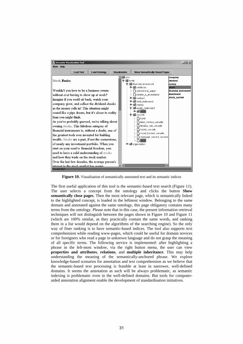
Figure 10. Visualisation of semantically annotated text and its semantic indices
The first useful application of this tool is the semantic-based text search (Figure 11). The user selects a concept from the ontology and clicks the button Show semantically close pages. Then the most relevant page, which is semantically linked to the highlighted concept, is loaded in the leftmost window. Belonging to the same domain and annotated against the same ontology, this page obligatory contains many terms from the ontology. Please note that in this case, the present information retrieval techniques will not distinguish between the pages shown in Figure 10 and Figure 11 (which are 100% similar, as they practically contain the same words, and ranking them in a list would depend on the algorithms of the searching engine). So the only way of finer ranking is to have semantic-based indices. The tool also supports text comprehension while reading www-pages, which could be useful for domain novices or for foreigners who read a page in unknown language and do not grasp the meaning of all specific terms. The following service is implemented: after highlighting a phrase in the left-most window, via the right button menu, the user can view properties and attributes, relations, and multiple inheritance. This may help understanding the meaning of the semantically-anchored phrase. We explore knowledge-based scenarios for annotation and text comprehension as we believe that the semantic-based text processing is feasible at least in narrower, well-defined domains. It seems the annotation as such will be always problematic, as semantic indexing is problematic even in the well-defined domains. But tools for computer-aided annotation alignment enable the development of standardisation initiatives.
31

Figure 11. A page with highest relevance, which is semantically linked to bond
6 Conclusion
In an earlier paper [5], we have analysed the interoperability of current CG tools. The CG community achieved the level of (certain) semantic interoperability of data as most tools support CGIF. But looking at the three “dialects” of CGIF implemented for instance in Amine, CharGer and CGWorld, we see that every author has his own opinion about what CGIF should be.
Regarding the interoperability of software modules, it is not a target at all. Most CG tools use different formats for processing the conceptual knowledge like CGIF, CGLF, FCG (+FO), Prolog+CG, CGLex, BCGCT, FOPC, KIF, XML – some CG XML or RDF. This makes the software exchange very difficult. In fact the shared CGIF “dialects” make the tools interoperable, as they can exchange at least resources.
There are no initiatives to standardise the CG display form and every tool implements it in a different graphical layout. Even tools like CharGer and CGWorld, which follow the CGIF standard very closely, parameterize different display characteristics of the conceptual graphs. A promising direction is to define mappings of the display form to some graphical standard like the Scalable Vector Graphics
32

(SVG) Specification (www.w3.org/TR/SVG/) or X3D (http://www.web3d.org/x3d/specifications/ x3d_specification.html). In general, the CG tools developers need some standards as they are all interested in exchange of resources and joint creation of testing data, given the relatively compact and unified nature of the CG community.
In the broader world of Semantic Web, however, many diverse approaches co-exist without attempts to exchange data or software. For instance, topic maps and RDF are proposed by two standardisation organisations, ISO and W3C respectively, which might be regarded as competitors. But in fact topic maps and RDF can be considered as complementary approaches for knowledge formalisation; especially if the focus is to find out the potential synergies between them (e.g. Ontopia automatically generates topic maps from RDF, see Figure 3 and http://www.ontopia.net/). Actually topic maps and RDF have a number of similarities. They define abstract models and syntax based on XML and both have models that are simple and elegant at one level but extremely powerful at another. However, such data interoperability considerations are made within a single application; in general the exchange of data and modules between applications is almost out of question.
Summarising the visualisation trends presented in the article, we conclude that the future trends seem to be unclear. On the one hand, we see that the graphical representation of semantic information is a strong tendency and is already adopted for interfaces oriented to end users (by e.g. topic maps navigation), so this direction is a promising feature of the knowledge-based applications. On the other hand, the majority of the isolated visualisation tools provide only interfaces for manual acquisition and browsing of formal statements, which looks like an approach with limited scalability. In this way the standardisation and interoperability considerations are still at a very initial phase, just included in the development schedule of the modern semantic-based systems. Acknowledgements. The work reported in this paper is partially supported by the project BIS-21++ funded by the European Commission in FP6 INCO via contract no.: INCO-CT-2005-016639.
References
[1] Tolk, A. and J. Muguira: The Levels of Conceptual Interoperability Model (LCIM), Fall Simulation Interoperability Workshop, Orlando, FL, September 2003.
[2] Tolk, A. "What Comes After the Semantic Web - PADS Implications for the Dynamic Web," PADS, 20th Workshop on Principles of Advanced and Distributed Simulation (PADS'06), 2006, pp. 55-62.
[3] Tolk, A. Composable Mission Spaces and M&S Repositories - Applicability of Open Standards Spring Simulation Interoperability Workshop, Washington, D.C., April 2004.
[4] Tolk, A., C. D. Turnitsa, and S. Y. Diallo, Ontological Implications of the Levels of Conceptual Interoperability Model, WMSCI2006, Orlando, July 2006.
33

[5] Dobrev P., CG Tools Interoperability and the Semantic Web Challenges, In P. Hitzler et al. (Eds.) Conceptual Structures: Inspiration and Application, Contributions to ICCS-06 - 14th Int. Conference on Conceptual Structures, Aalborg University Press, July 2006, pp. 42-59.
[6] Dobrev P., Knowledge Interoperability for the Semantic Web Applications, In G. Angelova et al. (Eds.) 2006 John Vincent Atanasoff Information Days, Proceedings of the Young Researchers Session, 4-6 October 2006, Sofia, Bulgaria, pp. 20-26, ISBN - 954-91743-5-2.
[7] ISO/IEC 13250:2003, Information technology - SGML applications - Topic maps, http://www.iso.org/iso/en/CatalogueDetailPage.CatalogueDetail?CSNUMBER=38068&ICS1=35&ICS2=240&ICS3=30, http://www1.y12.doe.gov/capabilities/sgml/sc34/document/0322.htm
[8] Handschuh, S. and S. Staab. CREAM: CREAting Metadata for the Semantic Web. Computer Networks: The International Journal of Computer and Telecommunications Networking, Volume 42 , Issue 5, 2003, pp. 579 – 598.
[9] Protégé, see http://protege.stanford.edu/ [10] Reynolds D., Thompson C., Mukerji J., Coleman D., An assessment of RDF/OWL
modelling, HPL-2005-189, October 28, 2005 [11] Sayers C., Node-centric RDF Graph Visualization, HP Technical Report, HPL-2004-60,
20040412, http://www.hpl.hp.com/techreports/2004/HPL-2004-60.pdf [12] http://www.cs.uga.edu/~ldeligia/PUBLIC/PROJECTS/PGV/ [13] http://semweb.salzburgresearch.at/apps/rdf-gravity/index.html (RDF GRAph VIsualization
Tool) [14] Sowa, J. Conceptual Structures: Information Processing in Mind and Machine, Addison-
Wesley, Reading, MA, 1984. [15] http://common-logic.org/docs/cl/24707-31-Dec-2006.pdf, Information technology —
Common Logic (CL) - A framework for a family of logic-based languages, ISO/IEC FDIS 24707, 2006.
[16] Ontology Definition Metamodel, Sixth Revised Submission to OMG/ RFP ad/2003-03-40 (http://www.omg.org/cgi-bin/doc?ad/06-05-01.pdf).
[17] Hayes P., IHMC, Translating Semantic Web languages into Common Logic, http://www.ihmc.us/users/phayes/CL/SW2SCL.html.
[18] Berners-Lee T., Reflections on Web Architecture, Conceptual Graphs and the Semantic Web, 2001/01/06, http://www.w3.org/DesignIssues/CG.html
[19] Corby, O., R. Dieng-Kuntz, and C. Faron-Zucker. Querying the Semantic Web with Corese Search Engine. ECAI 2004: 705-709
[20] Corby O., R. Dieng, C. Hebert. A Conceptual Graph Model for W3C Resource Description Framework. In ICCS 2000 Int. Conference on Conceptual Structures, 2000, LNAI 1867, Springer, 2000. pp-468-482, ISBN 3-540-67859-X
[21] Dobrev P., Toutanova K., CGWorld - Architecture and Features, In Proc. ICCS 2002 Int. Conference on Conceptual Structures, 2002, LNCS 2393, Springer 2002, pp. 261-270. The workbench is operational at http://larflast.bas.bg:8080/CGWorld.
[22] Dobrev P., A. Strupchanska and G. Angelova. Towards a Better Understanding of the Language Content in the Semantic Web, In Bussler, Ch. and D. Fensel (Eds.): Proc. AIMSA 2004, 11th Int. Conf. on Artificial Intelligence: Methodology, Systems, and Applications, Springer, LNCS 3192, 2004, pp. 267-276.
[23] Jena – A Semantic Web Framework for Java, http://jena.sourceforge.net
34

The Extent to Which Interoperability
Between CG and Non CG Tools
Can be Assessed Against the Semiotic Ladder
Peter Maybery and Simon Polovina
Faculty of Arts, Computing, Engineering and Science
Sheffield Hallam University
Sheffield, United Kingdom
[email protected], [email protected]
Abstract. This paper applies Stamper’s semiotic ladder to assess the extent to
which Conceptual Graph (CG) software tools can interoperate with each other
and others. The CharGer CG editor, the Amine multifaceted CG environment,
and the non-CG multi-agent simulation environment SeSAm were selected as a
representative set of tools for this purpose. Using these exemplars, the paper
explores through the semiotic ladder the interoperation that CG tools presently
reach. It identifies that an external XML converter is required for any
meaningful interoperability, and suggests this is where future research on
obtaining CG tools interoperability is directed.
Introduction
The aim of this study was to uncover the possibilities or limiting factors behind the
interoperability of CG modelling tools. The specific tools focused upon were:
Amine an Open Source Multi-Layer Java Platform designed for the development
of intelligent systems [1]. Amine which is the result of 19 years of extensive research
performed by Adil Kabbaj concerning several threads in Conceptual Graphs theory
and implementation [1].
Delugach (2000) [2] describes CharGer as a conceptual graph creator and editor
that is deliberate and explicitly used as a research tool aimed for conceptual graph
researchers to explore implementation issues in conceptual graph interfaces. CharGer
offers good promise for interoperation with SeSAm and Amine with the use of a
common language, XML. Additionally, CharGer has the capability of handling CGIF
therefore opening up a second opportunity for communication with Amine and
perhaps with the emergence of the common logic standard, SeSAm [3].
SeSAm (Shell for Simulated Agent Systems), provides a generic environment for
modelling and experimenting with agent-based simulation [4]. SeSAm is essentially a
MultiAgent Simulation tool which uses graphical user interfaces with UML style
mapping in the creation of simulated environments.
The aim and objective of this paper was to create an example CG in CharGer that
would then be exported to Amine for development, implementing the comprehensive
35

set of tools provided. This modified structure would then be exported to SeSAm with
the intension that the framework created could be employed by SeSAm to create the
basis of the simulated environment.
It must be noted that it was not an aim of Amine that interoperability would be
possible with other such CG and non CG tools. Taking this into account does not
detract from this investigation as the study will show what measure could be taken
into consideration for future interoperability developments.
Prolog+CG is another tool that is covered in this investigation, the name Prolog
itself is derived from PROgramming in LOGic and is an extension of Prolog platform
to include a conceptual extension, that it is now able to deal with simple CGs and
object orientated approaches.
In order to evaluate the success of interoperability and the level of satisfaction
gained, Stamper’s Semiotic Ladder was used to measure a comparison of each
software technology at every step of the ladder [5].
CG Tool Interoperability
To be able to assess the success of interoperability between the CG tools, a measure
of the communication possible needs to be recorded. To augment our comparison
using the Semiotic Ladder, we also refer to Dobrev’s modified Levels of Conceptual
Interoperability Model (LCIM) [6] [13].
Semiotics offers an alternate methodology to information system development, an
area that Stamper has evaluated since the 1960's. Developed upon the traditional three
levels of semiotics, comprising of syntactics, semantics and pragmatics, he extended
the ladder to include the social world, empirics and physical world. The original
purpose of the Semiotic Ladder was to ensure success of IT projects became
achievable, not only in the technical world, but additionally in the human world.
Figure. 1. Stampers semiotic ladder combined with the LCIM
Figure 1 displays how we view the combination of the LCIM and the Semiotic
Ladder. Level 0 of the LCIM is missing from Figure 1 as this denotes zero
communication between the applications [6]. This level does not easily synchronise
with any step of the Semiotic Ladder and was thus not considered further in our
36

discussion. LCIM 1 aligns with the first two runs of the semiotic ladder by
incorporating both technical and physical operations as defined by Dobrev [6].
Software
The routes of interoperability that will be investigated are based on the capabilities of
each individual tool. Figure 2 shows the key features of the software's functionality
that have been investigated and assessed.
Figure. 2. OO view of software with key features utilised.
This work will explain the findings from the attempted interoperation of the CG tools.
Stand Alone Prolog+CG 2.0 Vs Amine’s Prolog+CG
Historically, Prolog’s relations with CG have existed, from 1980, when Ennals used
the software to teach students how to construct linear semantic statements [7]. In
passing, therefore, we shall also refer to Prolog+CG1. Prolog+CG is seen as a legacy
system as stated online by Kabbaj himself as his focus has shifted to Amine which
incorporates Prolog+CG among the series of tools. This functionality, not available in
CharGer, offers a means by which CGs can be processed. CharGer on the other hand
offers a simple to use Graphical User Interface (GUI) for CG editing environment.
The interoperability of these tools would therefore be of great benefit.
1 When Prolog+CG is documented, it is version 2.0 that that is in question.
37

Figure. 3. Screen shot to show stand alone Prolog+CG
Figure 3 shows a basic example of how the “stand-alone” version looks and
functions. The screen is spilt, with one half dealing with the knowledge base and the
other with the queries. Each change made to the Prolog+CG requires the program to
be compiled before it can be run and queried.
In comparison with Amines version, several substantial changes have been made.
One example is that the primitives in Amine have been reduced [1]. These primitives
are extremely useful in speeding up coding practice and expanding functionality.
Kabbaj [1] suggests that by utilising API’s users are able to create their own specific
set of primitives, yet for a novice user this may be viewed as a limiting factor.
Syntactical difference do occur in the applications, Amines uses "[ ]" rather then "( )",
due to differences in naming conventions. The differences are continually growing
and cannot all be documented in this work.
Figure. 4. Amine’s GUI and console
38

Amine’s advantage with reference to Prolog+CG is highlighted (Figure. 4) with the
facility to load an ontology. This acts as the database of knowledge from which logic-
based questioning can be performed. The “consult” functionality of Amines
Prolog+CG allows for multiple querying of a single ontology. Without the ontology
Prolog+CG is still able to function but for full optimization of the tool an ontology is
a necessity.
Where Amine’s version of Prolog+CG misses in primitives it more than
compensates with improved functionality and interoperability. By supporting .db .prlg
.plgcg .pro .pcg extensions in comparison with .prlg .plgcg used by the stand-alone
“standalone” version, instantly Amine functionality exceeds that of its counterpart.
Clearly, the continuation of development of Prolog+CG, now reaching version 4.0,
brings with it many benefits with the modernisation of Adil Kabbaj’s work.
Charger to Amine
With the creation of transaction model in CharGer as displayed in Figure 5, the aim of
interoperation and rapid development could commence. We saved this document as
both XML and CGIF allowing for both paths of interoperability to be explored. In
comparisons to CharGer, Amine is a more complex tool in the design of ontologies
and MAS. Amine works on a hierarchical structure which means it holds limited
flexibility in relation to implementation of part developed designs. Amine demands
that at the Kernel level, a Lexicon Ontology is created, which then can be loaded to
activate functionality of the full tool suite.
Figure. 5. Example CG based on electricity generation and monitoring
Loading of the .XML transaction model created in charger was attempted, at kernel
level. Unfortunately this was not accepted. Amine is able to read .ONT, .XML and
.CGIF documents but all three file types vary in structure, dependent upon the original
source. There was limited success with the use of .CGIF as further practical
investigation lead to the ability of opening and use of the .CGIF file created in
CharGer. Amine allowed this inside the CG tools section of Amine but this was of
limited use as a lexicon ontology needed to be created first otherwise application
errors were shown when saving the changes.
39

Comparison of XML in Charger to Amine
Shown is a small snippet of XML code (Figure 6) taken from Amine. As
interoperation had not been possible, the investigation into the reasons for this
followed the path of comparison of XML. The layout formatting has been removed
from the charger XML (Figure. 6) and the father/child relationship information has
been removed for the purpose of this document. The objective of the comparison is to
understand at what point the interoperation is collapsing. As demonstrated by Brady,
the comparison of XML allows mapping of the same objects. There are small
similarities in naming conventions such as <type>, but beyond this the applications
both read/write the XML according to their implementation.
<Type>
<Key>Governing Body:National Grid</Key>
- <Lexicons>
- <Lexicon>
<Language>Transaction</Language>
- <Synonyms>
<Synonym>Governing Body:National Grid</Synonym>
</Synonyms>
</Type>
Figure. 6. Amine XML snippet
As the organisation of each tools XML is varied, it was envisaged at that start of this
project that interoperability would not be straightforward. The comparison of XML
and CGIF that took place was in order to identify the need for a common language
between CG and non CG tools. The key development would be to ensure that such
tools used XML as a common language therefore allowing interoperability between
the CG and non CG tool.
Charger to SeSAm
Brady covered this topic in the ICCS 2006 edition where he identified the use of
XRay2 as an XML editor to convert XML from charger to be used in SeSAm. His
investigation also unearthed that even when minor conversion changes are not
completed syntactic interoperability is lost. SeSAm uses Castor to bind and transform
the XML when saved. This is an Open Source data binding framework for Java™[8].
The use of Castor in the conversion from Java to XML, develops a richer depth of
XML in comparison to that of Amine but similar to that of CharGer. A possibility for
interoperation could be seen with the nature of SeSAm’s castor. This uses XML
schemas allowing for APIs to be created working in unison with SeSAm and
additional tools. Brady showed that CharGer and SeSAm break down in their
interoperability at the Semantic layer of the Semiotic ladder [9]. Many problems were
realised in the way the two tools interpreted the XML, leading to errors and failings at
the interoperability stage.
40

Amine to SeSAm
With the only successful interoperation with the tools pivoting on the CGIF
communication between CharGer and Amine, the feasibility of SeSAm’s complex
XML structure interoperating successfully was questionable. With SeSAm not
supporting the CGIF technology the chances of success at this level were reduced.
Attempting to open the .XML file created in Amine caused an error to be displayed:
Error
org.xml.sax.SAXException: XMLSeSAmModel is missing required attribute: version
Figure. 7. SeSAm displayed error
This equates to a basic error or warning information from the XML parser,
resulting in unsuccessful interoperation of the tools. A positive outlook for Amine and
SeSAm is that they are both capable of API extensions. As the nature of APIs is
abstract they work off the interfaces provided to them from the software. Inclusive
with this interoperability scenario, allowances for a plug-in to be developed between
the two tools is a promising area for interoperation.
Summary
It would be easy to write off the possibility of meaningful interoperability but to do so
would be unjust. As the results shown from this work should be of use in identifying
those areas where interoperation is currently failing and those where success is
becoming more apparent. With the use of the open source tools, allowances are made
so that personalised extensions could be made to aid the interoperability process.
Application of the Semiotic Ladder
Using the Semiotic Ladder [5] each tool has been assessed on its capability to satisfy
the requirements of each step with consideration of future possible benefits.
Usage of the semiotic ladder is usual in the context of breaking down problems in
order to foresee any project-critical issues. Having used a different approach and
assessed each CG tools at every level to show what provisions must be made to
satisfy the step, the semiotic ladder takes on a new role.
Stamper’s objective of each level dealing with distinctly different properties of a
sign [5] is aimed at reducing confusion of categorization. This is relatively clear cut
with respect to technical issues however the human level tends to bring with it
ambiguity. Additionally, the traditional beliefs behind semiotics and the definitions of
syntactic, semantic and pragmatic platforms have been questioned and criticised by
Peirce.
41

These are identified and explained by Cordeiro [10] culminating in a quotation of
Pierce questioning the validity of the pragmatic step: "what is called pragmatics is not
only theoretically antipragmatic, but also illogical". Even with this surrounding
ambiguity of the Semiotic Ladder recent works by Stamper [5] and Dobrev [6] sheds
new light on the situation which proves its worth with system development in
modern-day practices.
Figure.8 displays the assessed conceptual tools with regard to the investigations
undertaken in this paper and with a view to future possibilities.
Figure. 8. Applied Semiotic ladder to CharGer, Amine and SeSAm
Alternate Software Use & Future Work
In the light of the limited success with interoperability of the three selected CG tools,
attention to possible alternative applications to replace the role of one of the current
tools became a likely topic for future enquiry. With the greater understanding of each
42

application it became clear that an alternative solution might be possible with the use
of Protégé-OWL in the place of Amine, which was not designed with interoperability
in mind.
Protégé-OWL is a free, open-source platform that provides a growing user
community with a suite of tools to construct domain models and knowledge-based
applications with ontologies [11]. Protégé has a proven history of interoperation
through a plug-in developed and created by Klugl [12]. An added advantage for users
who are new to this software is that the surrounding material in relation to Protégé is
far superior in richness and availability. It certainly would be useful to explore the
idea of a plug-in to connect Amine and SeSAm.
Conclusions
The tools used in this document are three specialised tools that are the result of
research based projects. We investigated to see if it would be possible to find a way to
rapidly design and develop a simulated environment using each tool to expand and
develop the work of the last. Ultimately, as the interoperation of the tools was
minimal, it became increasingly difficulty to visualise that this specific combination
of programs could have any possibility of being successfully applied to a business
scenario. Without a common language or ability to read and write in the same
structures, interoperability of these types of tool will continue to hamper the progress
they make.
To assist in the process of achieving interoperability, we propose that XML
converters are provided as part of the interoperability of CG tools. Expecting each
tool to interoperate directly with each other is, in our view, a desirable but
unachievable goal. Energy expended on the development of such converters would
also identify any deficiencies in each tool for this purpose. Hence, the very
development of these converters would focus on where interoperability would be best
directed.
Dobrev [6] summarises that the work of interoperability is never finished and a line
can never be draw under interoperation. We would agree with such assumptions as
with the ever-changing nature of technology, possibilities for interoperation will
always be arising. This investigation has by no means exhausted all the possibilities
for interoperation. But to fully understand and become competent in each software
would require considerable more time and extensive effort than was possible during
this projects enquiry. We believe, however, that we have covered the major
possibilities and limiting factors of interoperation. During the scope of the project we
have not been able to identify any fulfilling success.
References
1. Kabbaj, A. (2007). Introduction : Amine platform [online]. Last accessed on 10
December 2006 at: http://amine-platform.sourceforge.net/.
43
2. Delugach, H.S. (2002). CharGer: A graphical conceptual graph editor [online].
Last accessed on 22 March 2007 at:
http://www.cs.nmsu.edu/~hdp/CGTools/proceedings/papers/CharGer.pdf.
3. Dori, D. (2004). ViSWeb – the visual SemanticWeb: Unifying human and machine
knowledge representations with object-process methodology. [online]. The VLDB
journal. 2 volume 13 ed., New York, Springer-Verlag, 125. Book from ACM Digital
Library last accessed 2007 at:
http://portal.acm.org.lcproxy.shu.ac.uk/dl.cfm?coll=portal&dl=ACM.
4. SeSAm (2006). Integrated environment for multi agent simulation [online].at:
http://www.simsesam.de/.
5. Stamper, R. (2007). Stumbling across a "Soft Mathematics" while exploring some
issues of Organisation, Law and Metaphysics. Unpublished Proposed Paper for the
ICCS 2007.
6. Dobrev, P. (2006). CG tools interoperability and the semantic web challenges. In:
Hitzler, P., Scharfe, H. and Ohrstron, P. (eds.). Inspiration and application.
Contributions to the ICCS 2006 14th International conference on Conceptual
Structures ed., Denmark, Aalborg University Press, 42-57.
7. Sowa, J. F. (1984). Conceptual structures information processing in mind and
machine. Addison-Wesley.
8. CASTOR (2005). The castor project [online].2007 at:
http://www.castor.org/index.html.
9. Brady, N., et al. (2006). Experiences and lessons from the practical interoperation
of CharGer with SeSAm. In: De Moor, A., Polovina, S., and Delugach, H. S. (eds.).
Denmark, Aalborg University Press, 32.
10. Cordeiro, J. and Filipe, J. (2004). The semiotic pentagram framework - A
perspective on the use of semiotics within organisational semiotics [online]. 11th
May. at: http://ltodi.est.ips.pt/jcordeiro/documents/19%20-
%20OS2004CordFil%20vfsub.pdf.
11. PROTEGE., (2006). What is protege? [online].2007 at:
http://protege.stanford.edu/overview/.
12. Klugl, F., R. Herrler and Oechslein, C. (2003). From simulated to real
environments: How to use SeSAm for software development. Springer-Verlag,, 13-
24.
13. Tolk, A. and Muguira, J., “ The Levels of conceptual Interoperability Model
(LCIM)”, Fall Simulation Interoperability Workshop, Washington, D.C., April 2004
44

Using interoperating conceptual tools to
improve searches in Kaj Munk
Ulrik Petersen
Department of Communication and PsychologyKroghstræde 3
DK – 9220 Aalborg EastDenmark
http://www.kajmunk.hum.aau.dk
Abstract. Query Expansion is a technique whereby a query in an infor-mation retrieval system is expanded with more terms, thus most likelyincreasing the number of relevant documents retrieved. In this paper, wedescribe a prototype of a system built around a number of interoper-ating conceptual structures tools, and how it uses Query Expansion toretrieve greater numbers of relevant documents. Thus the system is anexample of how interoperating conceptual structures tools can be usedto implement an information retrieval system.
1 Introduction
In what ways is it possible to query a corpus of natural language text concep-tually? That is the motivating question behind the research presented in thispaper. In order to answer this question partially, we have built a prototype sys-tem which incorporates three technologies, namely the Amine Platform [1–6],the Emdros corpus query system [7–10], and some natural language processingsoftware in the form of a lemmatizer and a part of speech tagger1. The system isable to increase the recall of queries for a given corpus of text, by expanding thequery with lemmas taken from an Amine ontology. The system could not havebeen built without the integration of the three key technologies mentioned. Inthis paper, we show how the system works in terms of its architecture, and howit is able to achieve greater recall.
The organizational context of the present research is the Kaj Munk ResearchCentre at Aalborg University, Denmark. Kaj Munk (1898-1944) was a Danishplaywright, pastor, poet, and author, who was very influential both in Danishcultural life and outside of Denmark in the period between the two World Wars.He was killed by the Germans in 1944 for his resistance stance.
The Kaj Munk Research Centre has bought the nachlass of Kaj Munk, and isin the process of digitizing the material for electronic publication on the web and
1 The lemmatizer and part of speech tagger employed in this research are the onesdeveloped by Centre for Language Technology (CST), Copenhagen, Denmark. Seehttp://www.cst.dk.
45

in other ways. The envisaged website will feature advanced search capabilitiesthat go beyond mere matching of text strings into the realm of semantics. In thisendeavour, conceptual structures play a key role, and software tools that dealwith conceptual structures become critical in the development of the underlyingdatabase technology.
The rest of the paper is laid out as follows. First, we introduce the litera-ture behind our system. Second, we give an overview of our system. Third, weoffer a more detailed look at the query-process that leads to semantic querying.Fourth, we give an example of the query process. Fifth, we give an analysis ofthe functionality in terms of the precision and recall of the system. Sixth, wereport on the method of achieving interoperability between the various parts ofthe system. Finally, we conclude the paper.
2 Literature review
Within the field of information retrieval, the notions of precision and recall areoften used to describe how well a search system performs. Briefly, recall is apercentage showing how many documents out of all relevant documents wereretrieved, while precision is a percentage showing how many of the retrieveddocuments are in fact relevant. For more information, see [11] and [12].
Query Expansion refers to a class of techniques in Information Retrieval inwhich a query given by the user is expanded with more query terms. The intent isalways either to increase the recall, or to increase the precision, or both. QueryExpansion is an old technique, but as demonstrated by the literature, a veryuseful technique. See for example, [13–15]. In so far as WordNet [16] can beconsidered an ontology, [13, 17, 15] among many others show that ontologies canprove valuable in the process of Query Expansion. The article [18] shows howcompound forms in Danish can be split into their respective lemmas, then usedas a basis for Query Expansion using a thesaurus.
The present author has built a corpus query system called Emdros. TheEmdros software is a generic query system for “analyzed or annotated text.”As such, the software accommodates “text plus information about that text.”2
In the present research, Emdros is the component that stores and queries boththe text corpus to be queried and the part of speech and lemma informationwith which each token is annotated. Additional information such as sentenceboundaries, paragraph boundaries, and noun phrase boundaries are also present,but are not used in the present research. Document boundaries, however, areused.
Emdros was written in C++, but has language bindings for several program-ming languages including Java. These language bindings are provided throughSWIG.3 For more information on Emdros, the reader is invited to consult both
2 This phrase is taken from [19], which is the PhD thesis of Crist-Jan Doedens. Emdrosimplements an extension of Doedens’ database model, and a subset of Doedens’ querylanguage. As such, Emdros can be seen as a derivate of the labours of Dr. Doedens.
3 See http://www.swig.org. See also [20].
46

the Emdros website4 and [7–10], all of which can be downloaded from the au-thor’s website5.
The Amine Platform is a platform intended for development of intelligentsystems and multi-agent systems [5]. It implements a large array of the technol-ogy components needed for building Knowledge Systems, including an ontologybuilder, a CG layer with concomitant CG operations, and a logic inference en-gine built around the integration of Prolog and CGs.6 The latter componentis called Prolog+CG, and is the software hub in the prototype which we havedeveloped.
3 System Overview
An overview of the system is given in Fig. 1. It is given in the form of a conceptualgraph, with an implied ontology of concept types such as the one given in Fig.2, and an implied relation hierarchy such as the one given in Fig. 3.
As can be seen from the ontology of concept types in Fig. 2, there are essen-tially two kinds of concepts in Fig. 1: Software and Data. Indeed, the relationtypes reflect this, as can be seen in Fig. 3, in which all subtypes of DataSoft-wareRole have the signature (Data,Software), and all subtypes of SoftwareSoft-wareRole have the signature (Software,Software). Consequently, the signature ofRole in our small conceptual graph of Fig. 1 must be (Bits,Software), indicatingthat the outgoing arrow on every relation always is attached to a concept of typeSoftware (cf. [21–24]).
There are three related but distinct flows of data in Fig. 1. The first flowstarts with the TextCorpus at the left edge of the leftmost row. This TextCorpus(which, in our case, is the corpus of published sermons of Kaj Munk) is readby CST’s part of speech tagger and lemmatizer to produce a pos-tagged andlemmatized corpus. This corpus is then read by a program which converts thecorpus to a number of CREATE OBJECT statements in the MQL query languageof Emdros. This produces the MQLCorpus, which is read by Emdros to producethe EmdrosDatabase at the bottom right hand corner of Fig. 1.
The second flow starts with the Amine Ontology Builder in the middle of thesecond row of Fig. 1, in which a domain expert creates an ontology of the domainwhich one would like to query. This produces the AmineOntology, which againis read by Amine’s Prolog+CG engine. Notice that the method of productionof the ontology is irrelevant for our prototype: It might just as well have beenproduced automatically. In our case, for simplicity and accuracy, we producedour own ontology “by hand.”
The third, and main, flow starts with the user query in the top right handcorner of Fig. 1. This query is read by the Prolog+CG programs written for our
4 http://emdros.org5 http://ulrikp.org6 However, Amine is much more than the few components listed here. In-
terested readers are invited to consult [5, 6] and the Amine Website:http://amine-platform.sourceforge.net
47

Fig. 1. Overview of our system
prototype, and is transformed, inside of Prolog, to an Emdros query based onthe type(s) from the AmineOntology given in the query. This Emdros query isthen fed to the Amine-Emdros bridge (through the interpreter-nature of AmineProlog+CG), which takes care of calling Emdros to query the EmdrosDatabasein the bottom right hand corner of Fig. 1. An answer comes back from Em-dros to the Amine-Emdros bridge. This answer is then further processed by theAmine-Emdros bridge in order to obtain not only the words found, but also theircontext.7 This result is then passed back to the Prolog+CG programs (throughthe interpreter-nature of Amine Prolog+CG), which then displays the results tothe user.
7 Emdros’s query language is designed to be very generic. As such, it uses a genericmethod of returning query results, which must then be interpreted in the context ofa given database. This interpretation usually involves retrieval of more objects fromthe database, such as whole sentences and their constituent tokens, and/or the titlesof the document(s) in which the results are found.
48

SoftwareData
Bits
TextCorpus LemmatizedCorpus MQLCorpus
AmineOntology EmdrosDatabaseCorpus
Fig. 2. A possible ontology for the concept types in our system
4 Querying
In our prototype, the user enters a query in the form of a set Q of types from theAmine ontology, along with an indication of whether supertypes or subtypes arewanted. If supertypes are wanted, a set Ei are constructed containing n levelsof supertypes of each term ti from Q. Similarly for subtypes, if subtypes arewanted.
An Emdros query is then constructed from the sets Ei, as follows. For each setEi, a single query fragment (technically, an “object block” retrieving an objectwith certain characteristics) is created, finding all objects of type token whoselemma is one of the terms ej in Ei, with Boolean disjunction being the operatorbetween the comparison. This could look as follows:
[token lemma=’party’ or lemma=’organization’ or lemma=’group’]
If there is more than one set Ei, then all permutations of all sequential ordersof the query fragments arising from each Ei is constructed, allowing for arbitraryspace in between each query fragment, and using an OR construct on stringsof blocks between each permutation. This results in a string of OR-separatedstrings of blocks, where each string of blocks represents one possible order of thequery terms. Finally, this string of OR-separated strings is wrapped in a blockindicating that the search is to be done within document boundaries.
Variations over this theme abound. For example, the number of levels n togo up or down in the ontology can be varied; sibling nodes may be considered;various measures of semantic distance may be employed in determining whichconcepts to include in the search; word-sense disambiguation may be performedbased on either the query terms and their cooccurrence in the query, or onthe documents actually stored in the database, or both; the context may bechanged from “Document” to a more restrictive “paragraph” or even “sentence”textual unit, thus increasing the likelihood that the query terms do in fact have
49

writer creator
originator caller interpreter
DataSoftwareRole SoftwareSoftwareRole
user
reader
Role
accessor
Fig. 3. A possible ontology for the relation types in our system
something to do with each other; named entity recognition may be performed,and named entities may be classified as per the ontology, thus aiding in increasingrecall; compounds may be split and used as the basis of further Query Expansion,as described in [18]; parsing or chunking of the texts may be performed so asto aid in identifying noun phrases that could aid in identifying more preciselywhere to search for given kinds of entries from the ontology; the ontology maybe enriched with part of speech information, such that this information can betaken into account when searching. Many other techniques have been tried overthe years, all built up around the single, simple idea of Query Expansion.
5 Query Example
In this section, we give an example of how the query-process works.
Consider the small ontology in Fig. 4. It is a sample ontology of conceptsfrom the political domain. Some of the concepts are annotated underneath withzero or more lemmas, separated by a vertical bar if more than one are present.Where no lemma corresponds to the type, the number of lemmas is zero.
Suppose the user enters a query in which the set Q of query types is {PartyMember, PoliticalEmployee }, and suppose that the user specifies that 3levels of subtypes are to be used for query expansion. In this case, two sets E0 ={ partymember, minister, primeminister, MP, parliamentmember } and E1 = {spindoctor } are constructed.
From these sets, the two object blocks:
50

PrimeMinisterprimeminister
Ministerminister
MemberOfParliamentMP|parliamentmember
PartyMemberpartymember
Partyparty
SpinDoctorspindoctor
PoliticalEntity
Entity
PoliticalEmployee
Fig. 4. A sample domain ontology of political language
[token lemma=’partymember’ OR lemma=’minister’
OR lemma=’primeminister’ OR lemma=’MP’
OR lemma=’parliamentmember’]
and
[token lemma=’spindoctor’]
are constructed. There are only two possible permutations of the order in whichtwo objects can occur (2 factorial), so these object blocks give rise to the queryshown in Fig. 5.
Briefly, the query means that, within the context of a document, two tokensmust be found, in either order, where the lemma of each token is either drawnfrom the sets E0 and E1. The “..” between each [token] object block meansthat the tokens need not be adjacent, but may be separated by arbitrary space,within the scope of the context Document.
This query is executed by the Amine-Emdros bridge, and the results post-processed in order to get the context of the “hits”, to be shown to the user byProlog+CG.
51

[Document
[token lemma=’partymember’ OR lemma=’minister’
OR lemma=’primeminister’ OR lemma=’MP’
OR lemma=’parliamentmember’
]
..
[token lemma=’spindoctor’]
OR
// Now the other order is tried...
[token lemma=’spindoctor’]
..
[token lemma=’partymember’ OR lemma=’minister’
OR lemma=’primeminister’ OR lemma=’MP’
OR lemma=’parliamentmember’
]
]
Fig. 5. Example Emdros query
6 Precision and Recall
As mentioned in Sect. 2, “recall” is a measure used within Information Retrievalto describe how well a system performs; in particular, it shows how many docu-ments were retrieved, divided by the total number of relevant documents for anygiven query. “Precision,” on the other hand, is the number of relevant documentsreturned, divided by the number of documents returned [12].
As confirmed by the research reported in [13–15,17], our system improvesrecall, and for the same reason that any Query Expansion technique in generalimproves recall: Since semantically similar terms are added to the query, moredocuments that contain semantically similar terms will be found. Since relevantdocuments may contain terms semantically similar to the original query terms,yet may not contain the actual query terms, increasing the number of documentsretrieved with semantically similar terms will most likely increase recall.
We have not evaluated our system formally on either precision or recall mea-sures, but this is something for future research.
7 Interoperability
This being a practical rather than theoretical paper, a number of comments onthe interoperability of the various system components are in order.
Both Amine’s ontology builder, Amine’s Prolog+CG, and Emdros can beviewed as tools for dealing with conceptual structures; Amine’s tools more sothan Emdros. Amine’s treatment of conceptual structures goes right to the core
52

of the very purpose for which Amine was created [5, 6]; thus a large part ofAmine’s codebase is centered around conceptual structures. Emdros, on the otherhand, has a different focus, namely that of storage and retrieval of annotatedtext. Given that lemmas represent a unified form for all forms of a given word,and given that this simplifies the task of assigning meaning to any given word,and given that lemmas play an important role in the selection of labels for theconcept types in many kinds of ontologies, and given that Emdros can storelemmas just as well as any other annotation, Emdros can be seen to be able todeal with conceptual structures.
The interoperability of Amine with Emdros was achieved through the use ofa “bridge” written in Java. This bridge is simply a Java class which instantiatesa connection to an Emdros datbase, receives queries, and “harvests” the results.The latter task involves processing the results of a query, then retrieving as muchcontext as necessary for the purposes at hand. This usually involves things likeretrieving document titles, all the words of the sentence surrounding a “hit”,retrieval of other objects necessary for display of the hits, etc.
Amine’s Prolog+CG supports calling arbitrary Java methods and instanti-ating arbitrary Java objects from within Prolog+CG. This is the method usedin our prototype system, where Prolog+CG instantiates an “Amine-Emdrosbridge” as a Java object, then calls methods on this bridge both to retrievequery results and to postprocess them as described above.
The present author found that Amine’s Java-integration made it easy tocall both the Amine API and the Emdros bridge. The ability to call arbitrarymethods in the host language (Java, in this case) was key in making the inter-operability work.
8 Conclusion
We have described a prototype system that enables a user to query a collectionof documents semantically rather than just by keyword. This is done through theuse of three key technologies: The Amine Platform, the Emdros Corpus QuerySystem, and a lemmatizer and part of speech tagger for the target language. Anontology is used to guide the process of query expansion, leading to a greaternumber of relevant documents being returned than would have been the case,had the program only found documents containing the original query terms.
Pointers to further research have already been given.
Acknowledgements
Thanks are due to cand.scient. Jørgen Albretsen, who provided the ontology usedin this prototype. Prof. dr.scient., PhD Peter Øhrstrøm provided many of theresearch ideas used in this research. The Danish Centre for Language Technology(CST) provided the part of speech tagger and lemmatizer used. Figure 1 was
53

drawn with the CharGer software written by Harry Delugach.8 The SWIG team9
made the integration of Emdros with Java possible. Finally, many thanks to Prof.Dr. Adil Kabbaj, who wrote the Amine-Platform, without which this researchwould have been much more difficult to carry out.
References
1. Kabbaj, A., Frasson, C., Kaltenbach, M., Djamen, J.Y.: A conceptual and contex-tual object-oriented logic programming: The PROLOG++ language. In Tepfen-hart, W.M., Dick, J.P., Sowa, J.F., eds.: Conceptual Structures: Current Practices– Second International Conference on Conceptual Structures, ICCS’94, CollegePark, Maryland, USA, August 1994, Proceedings. Volume 835 of Lecture Notes inArtificial Intelligence (LNAI)., Berlin, Springer Verlag (1994) 251–274
2. Kabbaj, A.: Un systeme multi-paradigme pour la manipulation des connaissancesutilisant la theorie des graphes conceptuels. PhD thesis, Univ. De Montreal,Canada (1996)
3. Kabbaj, A., Janta-Polczynski, M.: From PROLOG++ to PROLOG+CG : A CGobject-oriented logic programming language. In Ganter, B., Mineau, G.W., eds.:Proceedings of ICCS 2000. Volume 1867 of Lecture Notes in Artificial Intelligence(LNAI)., Berlin, Springer Verlag (2000) 540–554
4. Kabbaj, A., Moulin, B., Gancet, J., Nadeau, D., Rouleau, O.: Uses, improvements,and extensions of Prolog+CG : Case studies. In Delugach, H., Stumme, G., eds.:Conceptual Structures: 9th International Conference on Conceptual Structures,ICCS 2001, Stanford, CA, USA, July/August 2001, Proceedings. Volume 2120 ofLecture Notes in Artificial Intelligence (LNAI)., Berlin, Springer Verlag (2001)346–359
5. Kabbaj, A.: Development of intelligent systems and multi-agents systems withamine platform. [25] 286–299
6. Kabbaj, A., Bouzouba, K., El Hachimi, K., Ourdani, N.: Ontologies in AminePlatform: Structures and processes. [25] 300–313
7. Petersen, U.: Emdros — a text database engine for analyzed or annotated text.In: Proceedings of COLING 2004. (2004) 1190–1193 http://emdros.org/petersen-emdros-COLING-2004.pdf.
8. Petersen, U.: Evaluating corpus query systems on functionality and speed:TIGERSearch and Emdros. In Angelova, G., Bontcheva, K., Mitkov, R., Nicolov,N., Nikolov, N., eds.: International Conference Recent Advances in Natural Lan-guage Processing 2005, Proceedings, Borovets, Bulgaria, 21-23 September 2005,Shoumen, Bulgaria, INCOMA Ltd. (2005) 387–391
9. Petersen, U.: Principles, implementation strategies, and evaluation of a corpusquery system. In: Proceedings of the FSMNLP 2005. Volume 4002 of Lecture Notesin Artifical Intelligence., Berlin, Heidelberg, New York, Springer Verlag (2006)
10. Petersen, U.: Querying both parallel and treebank corpora: Evaluation of acorpus query system. In: Proceedings of LREC 2006. (2006) Available ashttp://ulrikp.org/pdf/LREC2006.pdf.
11. Baeza-Yates, R., Ribeiro-Neto, B.: Modern Information Retrieval. Addison-Wesley(1999)
8 http://charger.sourceforge.net9 http://www.swig.org, led by David Beazley.
54

12. Frakes, W.B., Baeza-Yates, R.: Information Retrieval: Data Structures and Algo-rithms. Prentice Hall (1992)
13. Voorhees, E.M.: Query expansion using lexical-semantic relations. In: SIGIR ’94:Proceedings of the 17th annual international ACM SIGIR conference on Researchand development in information retrieval, New York, NY, USA, Springer-VerlagNew York, Inc. (1994) 61–69
14. Mitra, M., Singhal, A., Buckley, C.: Improving automatic query expansion. In:SIGIR ’98: Proceedings of the 21st annual international ACM SIGIR conferenceon Research and development in information retrieval, New York, NY, USA, ACMPress (1998) 206–214
15. Moldovan, D.I., Mihalcea, R.: Using WordNet and lexical operators to improveinternet searches. IEEE Internet Computing 4(1) (2000) 34–43
16. Fellbaum, C., ed.: WordNet: An Electronic Lexical Database. MIT Press, London,England and Cambridge, Massachusetts (1998)
17. Smeaton, A.F., Quigley, I.: Experiments on using semantic distances betweenwords in image caption retrieval. In: Research and Development in InformationRetrieval. (1996) 174–180
18. Pedersen, B.S.: Using shallow linguistic analysis to improve search on Danishcompounds. Nat. Lang. Eng. 13(1) (2007) 75–90
19. Doedens, C.J.: Text Databases: One Database Model and Several Retrieval Lan-guages. Number 14 in Language and Computers. Editions Rodopi Amsterdam,Amsterdam and Atlanta, GA (1994) ISBN 90-5183-729-1.
20. Beazley, D.M., Fletcher, D., Dumont, D.: Perl extension buildingwith SWIG (1998) Presented at the O’Reilly Perl Conference 2.0,August 17-20, 1998, San Jose, California. Access online 2007-04-22:http://www.swig.org/papers/Perl98/swigperl.htm.
21. Sowa, J.F.: Conceptual Structures: Information Processing in Mind and Machine.Addison-Wesley, Reading, MA. (1984)
22. Sowa, J.F.: Conceptual graphs summary. In Nagle, T.E., Nagle, J.A., Gerholz,L.L., Eklund, P.W., eds.: Conceptual Structures: Current Research and Practice.Ellis Horwood, New York (1992) 3–51
23. Sowa, J.F.: Knowledge Representation: Logical, Philosophical, and ComputationalFoundations. Brooks/Cole Thomson Learning, Pacific Grove, CA (2000)
24. Petersen, U., Scharfe, H., Øhrstrøm, P.: Online course in knowledge representationusing conceptual graphs. On the web: http://www.huminf.aau.dk/cg/ (2001-2007)
25. Henrik Scharfe, Pascal Hitzler, P.Ø., ed.: Conceptual Structures: Inspiration andApplication. 14th International Conference on Conceptual Structures, ICCS 2006,Aalborg, Denmark, July 2006, Proceedings. In Henrik Scharfe, Pascal Hitzler, P.Ø.,ed.: Conceptual Structures: Inspiration and Application. 14th International Con-ference on Conceptual Structures, ICCS 2006, Aalborg, Denmark, July 2006, Pro-ceedings. Volume 4068 of Lecture Notes in Artificial Intelligence (LNAI)., Berlin,Heidelberg, Springer-Verlag (2006)
55

56

Adding Conceptual SIGNs to a Computer Memory Resident Data Structure
Based on the Phaneron of C. S. Peirce
Jane Campbell Mazzagatti
UNISYS Corporation, Blue Bell, PA, USA
Abstract. A computer data structure based on the Phaneron of C. S. Peirce has been described [1, 3, 4]. Although this data structure has significant commercial value it does not yet realize all of the concepts that Peirce attributes to the Phaneron [5]. Because it is not yet possible to attempt to implement a K data structure that does contain all the Peirce concepts, a method was needed that would facilitate the implementation of these concepts in phases. The solution being used is to define SIGNs, which are not fully formed, and use them as though they were.
1.0 Introduction
“Phaneroscopy is the description of the phaneron; and by the phaneron I mean the collective total of all that is in any way or in any sense present to the mind, quite regardless of whether it corresponds to any real thing or not” [2 3:284].
The Phaneron then contains anything that the mind requires to think, that would be experiential data and relational information, as well as processes or strategies to manipulate and/or retrieve information. All of these elements of the Phaneron would exist within the Phaneron and in the same triadic form that Peirce describes.
A rudimentary triadic structure, based on the Peirce phaneron, that creates a recording of basic data and relational information, has been described and implemented [1,3,4]. An API has been developed, to this software, that facilitates the creating and querying of this triadic structure called a Knowledge Store or K structure, for field/record data. Also, a GUI interface that uses the KStore API has been prototyped, for data analysis. This system is capable of returning the number of occurrences of any SIGN within the context or constraints of any set of SIGNs and therefore will support any type of analysis, of the data recorded in the K. The prototype includes a simple classification analytic, a Naïve Bayes classification analytic, a graphing tool as well as an aggregation function that can create re-aggregated forms of the original data.
The KStore data analysis system is very efficient for building the K structure for and querying, large field/record data sets. It can process static or streaming data and does not require any external structure such as cubes or indexes. [5]
57

Development of this K structure continues with the focus on incorporating more types of information into the K structure. Some of this information is conceptual or procedural, such as a data type attribute for a number or field value, which would require procedures to process them.
This conceptual or procedural type information within a K structure would have to be represented by a SIGN, a node in a K structure that was created through the recording of many interrelated experiences. These experiences that would be a part of an attribute SIGN, for example, can not at this time be well defined and so these SIGNs can not be fully formed within the current K structures.
The first examples of these types of SIGNs are the BOT (begin a thought) and EOT (end a thought) SIGNs that begin and end each sequence of events in a K structure. At this time the determination of the completion of a sequence is controlled by a coded algorithm and a hard-coded delimiter. For example, in a text universe a space would determine the end of a word and the coded algorithm encountering a space would complete a sequence that represents a word and initialize a new sequence. Eventually it is planned that the K structure will be able to determine its delimiters from past recorded sequences within the K structure itself. Algorithms to do this are being tested.
2.0 Basic K Structure
The Peirce writings suggest recording information sequences in a three dimensional structure using the basic triad shown in Figure 1.
Figure 1. Basic Triad
2.1 Recording Event Sequences
K structure recordings of the event sequences ‘cat’ and ‘cats are furry’ would look like the K structures diagrammed in Figure 2 and Figure 3, respectively.
58

Figure 2. K recording of the sequence ‘cat’
Figure 3. K recording the sequence ‘cats are furry’
2.2 Recording Commercial field/record data
Given the data set in Figure 4, the resulting K structure, shown in Figure 5, will have three distinct levels.
In Figure 5, at the lowest level are the elemental events or sensors, in this case the alphanumeric character set. The middle level contains the recordings of the elemental event sequences from the level below that occur in this environment, that is, sequences of letters that represent field values. At the highest level are the recordings of sequences of field values that make up the records.
59

Figure 4. Sample data set
Figure 5. K recording of the sample data set
K structures created using the basic triad are truly three dimensional structures. All the K node pointers are bi-directional allowing the structure to be traversed left-to-right and up-and down, and in any combination of directions. For example, in the K structure Fig.5 if I want to find all the records that contain the character ‘P’, I would start at lowest level SIGN for ‘P’ and follow the dotted line to the field variable level sequence that contains ‘P’. There is only one field variable that contains ‘P’, traversing that field variable sequence to its end using the solid line I find there are three dotted lines pointing to the records that contain a field variable that contains the character ‘P’. For more examples of traversing the K structure to obtain information see the patents [3.4] and ‘The Practical Peirce’ [5].
60

3. Incorporating more information into a K Structure
The K structure in Figure 5 is a K recording of field/record data only. Any processing of the recorded data would be accomplished by executing coded algorithms that traverse the K structure referencing the data. The K structure in Figure 7 also contains the SIGNs, BOT and EOT. These SIGNs represent something other than the actual data event elements.
The K structure is proving to be a very flexible data structure with the potential to hold information that would typically be stored in multiple data structures or as part of coded algorithms.
3.1 SIGNs that define K structure
Initially, the BOT and EOT SIGNs were created to allow coded algorithms to locate the physical beginning and end of event sequences within the K structure. Eventually, it became evident that the BOT and EOT SIGNs, such as the ones in Figure 4 and 5, actually simulate the physical beginning and ending of event sequences and may also be used to represent some concept or attribute associated with the event sequence. For example, the EOTs at the end of the event sequences in the middle level of the K in Figure 7 may also contain the information that identifies this event sequence as a field variable value.
An EOT SIGN representing such a concept would have been developed from many other experiences, also recorded in the K, and be composed of many lower level SIGNs, in other words fully formed within the K. Experiences that would have recognized the pattern of blank space between complete event sequences, ending one sequence and beginning another, would have created a SIGN such as the BOT SIGN that would trigger anticipation of a new sequence of letters.
The ultimate computer implementation of a Phaneron or K as described by Peirce would have a very small set of coded algorithms to simulate the creation of SIGNs and habit, the strengthening of the connections between the SIGNs from the stimulation of a sensor set. The structure itself as it is developing, will contain a record of the experiences in relation to all other experiences and strategies for responding to those experiences, all in the form of SIGNs connected to SIGNs.
3.2 SIGNs that represent Concepts
In the example above, Figure 5, all the SIGNs created at the middle level are of the same type, so it is easy to identify all the field variables using the EOT. However, as we incorporate more types of information into the K, multiple event sequence types will occur at any given level and the sequence types must be specified.
For example, one sequence of events from the available alphanumeric events might be ‘abcdefg…z’ representing the alphabetical order. Figure 6 shows the alphabetic sequence of events that would be at the same level as field variable, with a new SIGN embedded in the sequence that identifies it as an alphabetic order.
61

This attribute SIGN represents concepts we can’t fully realize in K at this time and its function will have to be realized by a coded algorithm. This attribute SIGN, however, differentiates this sequence from other types of sequences at the same level and established relationships between the alphabetic order and all other sequences containing those SIGNs in the alphabetic sequence.
Figure 6. K recording of the alphabet with an alphabet concept SIGN
Figure 7 shows a K that contains the event sequences ‘bat’, ‘cat’ and ‘fat’ (the larger ovals) and the event sequence that defines the alphabetic order (the smaller ovals).
Figure 7. K recording of event sequences
A general coded algorithm can use any ordering event sequence stored in the K, to reference any type of event sequences also stored in the K. Such an algorithm would use the alphabetic order event sequence to reference the word event sequences and select the references in the proper alphabetic order.
62

There are many other concept types that might be associated with event sequences at this K level. Field values, names, numbers, column names, nouns, verbs, pronouns and so on, this list is infinite. Many event sequences may also have multiple concept types associated with them. Ultimately, as Peirce says, all that is before the mind is in the Phaneron.
4. Mapping Peirce concepts into the K Structure
“This illustration has much more pertinence to pragmatism than appears at first sight; since my researches into the logic of relatives have shown beyond all sane doubt that in one respect combinations of concepts exhibit a remarkable analogy with chemical combinations; every concept having a strict valency.” [2 3:469]
“One very important triad is this: it has been found that there are three kinds of signs which are all indispensable in all reasoning; the first is the diagrammatic sign or icon, which exhibits a similarity or analogy to the subject of discourse; the second is the index, which like a pronoun demonstrative or relative, forces the attention to the particular object intended without describing it; the third [or symbol] is the general name or description which signifies its object by means of an association of ideas or habitual connection between the name and the character signified.” [2 3:369]
The concepts of valence, icon, index, symbol and others defined by Peirce, if generated from within a K, would have a very complex defining K structure. The ability to create these SIGNs partially formed (without any defining K structure) and process them using coded algorithms gives the potential to explore Peirce’s cognitive model or Phaneron and the interaction of these concepts even though the SIGNs are incomplete.
References
1. Mazzagatti, Jane C.: “A Computer Memory Resident Data Structure Based on the Phaneron of C. S. Peirce” in Inspiration and Application, Contributions to ICCS 2006 14th International Conference on Conceptual Structures ICCS 2006: Aalborg University Press 2006: Pascal Hitzler, Henrik Scharfe eds.: July 2006, pp. 114-130.
2. Peirce, Charles S.: Collected Papers of Charles Sanders Peirce: 8 vols.: Vols. 1-6 ed. Charles Hartshorne and Paul Weiss: Vols. 7-8 ed. Arthur Burks: Cambridge: Harvard University Press, 1931-58.
3. UNISYS Patent number 6,961,733 – (http://patft.uspto.gov/netacgi/nph-Parser?Sect1=PTO2&Sect2=HITOFF&p=1&u=%2Fnetahtml%2FPTO%2Fsearch-bool.html&r=3&f=G&l=50&co1=AND&d=PTXT&s1=mazzagatti.INNM.&OS=IN/mazzagatti&RS=IN/mazzagatti).
4. UNISYS Patent number 7,158,975 – (http://patft.uspto.gov/netacgi/nph-Parser?Sect1=PTO2&Sect2=HITOFF&p=1&u=%2Fnetahtml%2FPTO%2Fsearch-bool.html&r=2&f=G&l=50&co1=AND&d=PTXT&s1=mazzagatti.INNM.&OS=IN/mazzagatti&RS=IN/mazzagatti).
5. Zuchero, John: The Practical Peirce : An Introduction to the Triadic Continuum : New York iUniverse 2007 : ISBN 0-595-44112-2.
63

64
Interoperability: The next steps for Amine Platform
Adil KABBAJ INSEA, Rabat, Morocco
Abstract. Amine is a multi-layer platform and a modular integrated development Environment, based on CG theory and suited for symbolic programming, intelligent system programming and intelligent agents programming. Amine architecture is composed of five layers: ontology layer, algebraic layer, process/engine/programming layer, agents and multi-agent systems layer, and application layer. Interoperability is among the next steps for Amine platform. The paper specifies also other directions for future works on Amine.
1. Introduction: Amine architecture Amine is a multi-layer platform and a modular integrated development
Environment (IDE), based on CG theory and suited for symbolic programming, intelligent system programming and intelligent agents programming [1, 2]. Amine is composed of five hierarchical layers (Figure 1): a) Ontology layer: It concerns the creation, edition and manipulation of multi-
lingua ontology which provides the “conceptual vocabulary” and the semantic of a domain.
b) Algebraic layer: this layer provides several types of structures and operations. Amine offers elementary data types (AmineInteger, AmineDouble, String, Boolean, etc.), structured descriptions (AmineSet, AmineList, Term, Concept, Relation and Conceptual Graph) and structured patterns (structured descriptions that are generic; they contain variables). In addition to operations that are specific to each kind of structure, Amine provides a set of basic common operations (clear, clone, toString, etc.) and various matching-based operations (match, equal, unify, subsume, maximalJoin and generalize) common to all structures. Operations on structured patterns take into account variable binding (the association of a value to a variable) and binding context that specifies the programming context which determines how variable binding should be interpreted and resolved, i.e. how to associate a value to a variable and how to get the value of a variable.
Amine structures and operations (including CG structure and CG operations) are APIs that can be used by any Java application. They are also “inherited” by the higher layers of Amine.
Amine uses “Java interfaces” to guarantee genericity and openness of Amine to Java: new structures, that implement these Java interfaces, can be integrated as new structures to Amine.
65

c) Programming layer: Three complementary programming paradigms are provided by Amine: a) pattern-matching and rule-based programming paradigm, embedded in the PROLOG+CG language which is an object-based and CG-based extension of the PROLOG language, b) activation and propagation-based programming paradigm, embedded in the SYNERGY language and based on executable CG, and c) ontology or memory-based programming paradigm which is concerned by incremental and automatic integration of knowledge in an ontology (that can be considered also as an agent memory) and by information retrieval, classification, inferences, learning and other related ontology/memory-based processes.
d) Agents and Multi-Agent System layer: Amine can be used in conjunction with a Java Agent Development Environment to develop multi-agent systems. Amine does not provide the basic level for the development of multi-agent systems (i.e. implementation of agents and their communication capabilities using network protocols) since this level is already offered by other open source projects (like JADE1). Amine provides rather “plug-ins” that enables its use with these projects in order to develop agent-based applications and multi-agents systems.
e) Application layer: various kinds of applications can be developed, using Amine (or a subset of Amine): Knowledge Based Systems, Ontology based applications, natural language processing applications, problem solving applications, planning applications, reasoning based applications, learning based applications, multi-agents applications, etc.
Amine provides also several graphical user interfaces (GUIs): Ontology editor
GUI, CG editor GUI, CG Operations GUI, Ontology processes GUI, Dynamic Ontology GUI, Prolog+CG GUI and Synergy GUI. Amine Suite Panel provides an access to all GUIs of Amine, as well as an access to some ontology examples and to several tests that illustrate the use of Amine structures and their APIs. Amine has also a web site, with samples and a growing documentation.
Amine five layers form a hierarchy: each layer is built on top of and uses the lower layers (i.e. the algebraic layer inherits the ontology layer; the programming layer inherits the ontology and the algebraic layers, etc.). However, a lower layer can be used without the higher layers: the ontology layer (i.e. with the associated APIs) can be used directly in any Java application without the other layers. Algebraic layer (i.e. with the associated APIs) can be used directly too, etc. Among the goals (and constraints) that have influenced the design and implementation of Amine was the goal to achieve a higher level of modularity and independence between Amine components/layers.
1 jade.tilab.com/
66
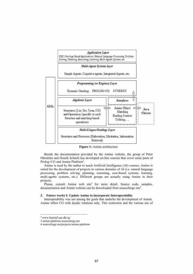
Figure 1: Amine architecture
Beside the documentation provided by the Amine website, the group of Peter
Ohrström and Henrik Scharfe has developed on-line courses that cover some parts of Prolog+CG and Amine Platform2.
Amine is used by the author to teach Artificial Intelligence (AI) courses. Amine is suited for the development of projects in various domains of AI (i.e. natural language processing, problem solving, planning, reasoning, case-based systems, learning, multi-agents systems, etc.). Different groups are actually using Amine in their projects.
Please, consult Amine web site3 for more detail. Source code, samples, documentation and Amine website can be downloaded from sourceforge site4.
2. Future works I: Update Amine to incorporate Interoperability
Interoperability was not among the goals that underlie the development of Amine. Amine offers CG with dyadic relations only. This restriction and the various use of
2 www.huminf.aau.dk/cg/ 3 amine-platform.sourceforge.net 4 sourceforge.net/projects/amine-platform
67

CG in Amine (which provide various programming contexts) lead to the adoption of a CGIF notation that has some difference with the standard.
Now and since interoperability is becoming an important issue in respect to CG tools, we are extending Amine in order to take into account CG with n-adic relations and CG notations that are conform to CG standard.
In addition to CG, Ontology is also concerned by interoperability. Another extension of Amine will concern the development of interfaces between Amine’s Ontology and standard notations in the growing “Formal/Applied Ontology” field and Semantic Web technology (like XML, RDF, OWL, etc.).
3. Future works II
Current and future works concern all layers of Amine (see the next section for more detail) as well as the development of applications in various domains: reasoning, expert systems, ontology-based applications, natural language processing, problem solving and planning, case-based systems, multi-strategy learning systems, multi-agents systems, intelligent tutoring systems, etc. Here is a non-exhaustive list of some future works. a) Update Amine to incorporate Interoperability. This point was discussed in section
2. b) Addition of a “Knowledge Base (KB) Layer”, between Ontology and Algebraic
layers, that will enable the definition, editing and use of several KB, distinct from but supported by the underlying ontology.
c) Extension of the Algebraic Layer to include general CG, i.e. CG with n-adic relations and CG that are not necessarily functional.
d) Addition of an “Inference and Learning Strategies Layer”, between Algebraic and Programming layers, that will be considered as memory-based strategies to provide an operational memory-based and multi-strategy learning programming paradigm.
e) Enhance CG and Ontology editors and (automatic) drawing. Consider CG with n-adic relations and update CG editor to include this extension.
f) Enhance CG operations: Consider the case of CG with n-adic relations and consider the case of general CG; CG that are not functional.
g) Enhance Prolog+CG: Consider the development of a better editor and provide a set of primitives similar to the set of primitive goals in standard Prolog.
h) Enhance Synergy: Consider a full implementation of Synergy. Currently, only a subset of Synergy has been implemented and integrated to Amine; composed coreference and object-oriented aspects of Synergy were not considered. Also, provide a rich set of primitives for the Synergy language.
i) Enhance Dynamic Ontology: the current implementation of the integration process considers heterogeneous ontology/KB (definition, situation, individual, etc.). Several applications require homogeneous ontology/KB (definition only, situation only, etc.). Implementation of the integration process for homogeneous ontology/KB will be more efficient than its current implementation, dedicated to heterogeneous ontology/KB.
j) Enhance the MAS Renaldo. Consider a better formulation of agent knowledge. Develop a visualization of agent behaviour. Consider the reactivity of agents.
68

k) Develop a Natural Language Processing project (semantic analysis, question/answering, generation) around a subset of natural language (i.e. a Controlled Language like ACE).
4. Conclusion
With the Ontology layer, Amine provides not only powerful tools for Ontology-based applications, but also the semantic support for symbolic programming, intelligent system programming and agents programming. The great variety of structures and operations of the Algebraic layer, especially CG and CG operations, is valuable for various applications in different domains. Programming layer, with Prolog+CG, Synergy and Ontology-based processes, makes Amine a suitable IDE for symbolic programming and intelligent system programming. These layers with the agent layer provide the possibility to develop different kinds of agents and multi-agents systems.
Future works concern enhance and extension of current Amine’s layers, addition of new layers, and incorporation of Interoperability of Amine with other CG and Ontology tools.
We hope that Amine will federate works and efforts in the CG community (and
elsewhere) to develop a robust and mature modular IDE, suited for symbolic programming, intelligent system programming and intelligent agents programming.
References [1] Kabbaj, A. 2006. Development of intelligent systems and multi-agents systems with amine platform. In Henrik Scharfe, Pascal Hitzler, P. Ohrström., ed.: Conceptual Structures: Inspiration and Application. 14th International Conference on Conceptual Structures, ICCS 2006, Aalborg, Denmark, July 2006, Proceedings. Volume 4068 of Lecture Notes in Artificial Intelligence (LNAI)., Berlin, Heidelberg, Springer-Verlag, 286–299. [2] Kabbaj, A, Bouzouba K., El Hachimi K. and al. 2006. Ontologies in Amine Platform: Structures and Processes, In Henrik Scharfe, Pascal Hitzler, P. Ohrström., ed.: Conceptual Structures: Inspiration and Application. 14th International Conference on Conceptual Structures, ICCS 2006, Aalborg, Denmark, July 2006, Proceedings. Volume 4068 of Lecture Notes in Artificial Intelligence (LNAI)., Berlin, Heidelberg, Springer-Verlag.
69

70

CPE Design Considering Interoperability
Heather D. Pfei�er, Nemecio R. Chavez, Jr., Joseph J. Pfei�er, Jr.
New Mexico State Universityemails: {hdp, nchavez, pfei�er}@cs.nmsu.edu
Abstract The Conceptual Programming system (CP) was upgraded tothe Conceptual Programming Environment (CPE) back in 2004. At thattime, the building and storage of Conceptual Graphs were implementedin a modular fashion in order to allow not only interoperability withCPE, but also to share modules with other applications. Since then amodule has been added to the environment for doing foundational rea-soning operations, projection and maximal join. CPE's interoperabilityis also being enhanced by allowing not only C and C++ applications toaccess this module, but developing this knowledge system so that a storyunderstanding system, written in Java, can interface with it. Future workis beginning on developing a module that will allow interoperability withCPE and the Common Logic Standard.
1 Introduction
The Conceptual Programming system (CP) was originally developed as a sin-gle, standalone application [1,2] that handles temporal, spatial and constraintinformation [3,4] using a knowledge base of Conceptual Graphs (CGs) [5]. Morerecently, the New Mexico State University group has begun to investigate alter-native data structures and models to allow other applications and systems tocommunicate with the CP application [6,7,8]. By 2004 the Conceptual Program-ming Environment (CPE) had been introduced with its new modular, multi-component design to increase the �exibility of the environment and to allowmodules to be used outside of the environment by other systems [9]. At thattime, the main form of interoperability was by using the CGIF1 interchange for-mat. CPE included simple wrapper modules to allow other languages, besides Cand C++, to use the CGIF module. The knowledge system has now expandednot only into the storage and retrieval of graphs, but also into improving theperformance of foundational reasoning operations [10]. When redesigning thealgorithms and data structures for the reasoning operations, it was taken intoaccount that CGs can be represented by a triples data structure many times seenin databases. Other researchers have also exploited this data structure [11,12] inrepresenting CGs. NMSU is unique in using the data structures directly by thereasoning algorithms, not just in the knowledge representation used for storage
1 The current archived copy of CGIF from the ICCS2001 workshop is located at:http://www.cs.nmsu.edu/~hdp/CGTools/cgstand/cgstandnmsu.html#Header_44
71

and retrieval. To show the usefulness of this research, CPE has been used as theknowledge base of objects with query-answer facilities in connection with a newstory understanding system.
2 Story Understanding System
This story understanding system is in the process of being built at New MexicoState University using a multi-agent design [13]. The primary goal is for thestory understanding system to perform in-depth story understanding by usingboth world and prototype knowledge through a knowledge base. A short storythat has been tested by the new understanding system is the following text:
Down at the very bottom of the pitcher there was a little water and thethirsty crow tried every way to reach it with her beak. But the pitcher wasmuch too tall. The crow got thirstier and thirstier. At last she thoughtof a clever plan. One by one she dropped pebbles into the pitcher. Everypebble made the water rise a little higher. When the water reached thebrim, the thirsty crow was able to drink with ease [14].
3 Knowledge Base
The knowledge base is divided into two categories: 1) world knowledge and 2)prototype knowledge. The world (or object) knowledge comes from a commonsense knowledge system that can perform some form of non-monotonic reason-ing, has the ability to change its mind and makes inferences when there is hardlyenough information available to make any inference; while the prototype knowl-edge comes from the new story understanding system. The world knowledgedescribes objects and their relationship with other objects. This part acts as abasic query-answer facility being able to �nd elements within the story and howthey relate to other objects in the story. The prototype knowledge is a higher-order or abstract knowledge. Unlike the world knowledge, this knowledge is verydependent on the domain context of the text being understood.
Given the text de�ned above, an English version of a knowledge base wouldneed to stored the following propositions:
Water is a liquid.
Liquid is a thing.
All pitchers have a brim, bottom, and top.
Containers are things that hold things.
Pebbles are things.
Crows are birds.
Birds are animals that have beaks.
Animals are live things.
Live things are things that need air, food, water, and shelter.
72

3.1 Basic Knowledge About Objects
This part of the knowledge base has open world knowledge and is not speci�c toany particular domain. This is where CPE and its modules are very applicable.The English knowledge given above can be translated into the following CGIFnotation.
;The first relations sets up the type hierarchy for the concepts
found in the knowledge base;
(GT [TypeLabel: `Entity'] [TypeLabel: `Thing'])
(GT [TypeLabel: `Thing'] [TypeLabel: `Liquid'])
(GT [TypeLabel: `Thing'] [TypeLabel: `Container'])
(GT [TypeLabel: `Thing'] [TypeLabel: `Pebble'])
(GT [TypeLabel: `Thing'] [TypeLabel: `LiveThing'])
(GT [TypeLabel: `Liquid'] [TypeLabel: 'Water'])
(GT [TypeLabel: `Container'] [TypeLabel: `Pitcher'])
(GT [TypeLabel: `LiveThing'][TypeLabel: `Animal'])
(GT [TypeLabel: `Animal'][TypeLabel: `Bird'])
(GT [TypeLabel: `Bird'][TypeLabel: `Crow'])
;The next set of Conceptual Graphs are definitional for giving
structure to some of the concepts in the type hierarchy just
defined;
[Pitcher*p1:@every ;all pitchers;]
(ATTR ?p1 [Bottom])
(ATTR ?p1 [Top])
(ATTR ?p1 [Brim])
(HOLD [Container*c1] [Thing:@{}]
(PART [Bird] [Beak])
(NEED [PROPOSITION:
(BREATHE [LiveThing*lt1] [Air])
(EAT ?lt1 [Food])
(DRINK ?lt1 [Water])
(LIVEIN ?lt1 [Shelter])])
Yet this knowledge does not have to be added directly into the story under-standing system. The story understanding system can use CPE completely as aquery-answer knowledge system, where graphs and parts of graphs are returnedto the story system with a Java wrapper set of routines. All the knowledge in theCPE knowledge base is totally independent of the story understanding systemand can be used by any application.
73

3.2 Prototype Knowledge
The prototype knowledge builds understanding that goes beyond the given text.However, this knowledge is part of the story understanding system and its rele-vance to the topic of this paper is in how it interoperates with the world knowl-edge system. The current design for testing di�erent knowledge systems with thestory understanding system is to have a �xed application programming interface(API) for all knowledge systems to be used.
Originally it was believed that all basic knowledge had to be stored in allknowledge systems being used by the story understanding system. So some pre-liminary work was done addressing the translation of data from one knowledgesystem to another [15]. However, it turns out how the knowledge is stored in theknowledge system is not important, only that the �xed API is necessary for thestory understanding system to be able to move between knowledge systems.
4 Future Research
Work has begun on the API between the prototype knowledge and the worldknowledge to use the new Common Logic standard, CLIF2. This will give aconsistent API that will not have to change if another knowledge reasoningsystem is to be used with the story understanding system. It will also allowCPE to have available a sharable CLIF module for standardized communicationwith other applications or systems.
Work is also proceeding on interfacing CPE to John Sowa's FMF blackboardapplication [16]. Modules are being investigated that will take input in eitherCLCE [17] or ACE [18] format.
References
1. Pfei�er, H.D., Hartley, R.T.: The Conceptual Programming Environment, CP:Reasoning representation using graph structures and operations. In: Proc. of IEEEWorkshop on Visual Languages, Kobe, Japan (1991)
2. Pfei�er, H.D., Hartley, R.T.: The Conceptual Programming Environment, CP. InNagle, T.E., Nagle, J.A., Gerholz, L.L., Ekland, P.W., eds.: Conceptual Structures:Current Research and Practice. Ellis Horwood Workshops, Ellis Horwood (1992)
3. Hartley, R.T.: A uniform representation for time and space and their mutualconstraints. In Lehmann, F., ed.: Semantics Networks, Oxford, ENGLAND (1992)
4. Pfei�er, H.D., Hartley, R.T.: Temporal, spatial, and constraint handling in theConceptual Programming Environment, CP. Journal for Experimental and Theo-retical AI 4(2) (1992) 167�182
5. Sowa, J.F.: Conceptual Structures: Information Processing in Mind and Machine.Addison-Wesley, Reading, MA (1984)
6. Pfei�er, H.D., Hartley, R.T.: Visual CP representation of knowledge. In Stumme,G., ed.: Working with Conceptual Structures - Contributions to ICCS 2000. (2000)175�188 Shaker-Verlag.
2 The current Common Logic standard is located at: http://cl.tamu.edu/
74

7. Pfei�er, H.D., Hartley, R.T.: ARCEdit - CG editor. In: CGTools Workshop Pro-ceedings in connection with ICCS 2001, Stanford, CA (2001) [Online Access: July2001] URL:http://www.cs.nmsu.edu/ hdp/CGTOOLS/proceedings/index.html.
8. Hartley, R.T., Pfei�er, H.D.: Data models for Conceptual Structures. In: Foun-dations and Applications of Conceptual Structures, Contributions to ICCS 2002,ICCS2002 (2002)
9. Pfei�er, H.D.: An exportable CGIF module from the CP environment: A prag-matic approach. In Wol�, K.E., Pfei�er, H.D., Delugach, H.S., eds.: ConceptualStructures at Work. Volume LNAI of 3127., ICCS2004, Springer (July 2004) 319�332
10. Pfei�er, H.D.: The E�ect of Data Structures Modi�cations On Algorithms forReasoning Operations. PhD thesis, New Mexico State University, Las Cruces, NM(2007)
11. Kabbaj, A., Moulin, B.: An algorithmic de�nition of CG operations based on abootstrap step. In: Proceedings of ICCS'01. (2001)
12. Skipper, D., Delugach, H.: OpenCG: An open source graph representation. Inde Moor, A., Polovina, S., Delugach, H., eds.: First Conceptual Structures ToolInteroperability Workshop, CS-TIW 2006, Aalborg Universitetsforlag (2006) 48�57
13. Chavez, Jr., N.R., Hartley, R.T.: The Role of Object-Oriented Techniques andMulti-Agents in Story Understanding. In: Proceedings of the International Confer-ence on Integration of Knowledge Intensie Multi-Agent Systems, Waltham, Mass,KIMAS 2005 (2005)
14. Aesop: Aesop's fabeles. Doubleday & Company, Garden City Books (1954)15. Pfei�er, H.D., Chavez, Jr., N.R., Hartley, R.T.: A generic interface for communica-
tion between story understanding systems and knowledge bases. In: Richard TapiaCelebration of Diversity in Computing Conference, Albuquerque, NM (2005)
16. Sowa, J.F.: Architectures for intelligent systems. IBM Systems Journal 41(3)(2002) 331�349
17. Sowa, J.F.: Common Logic Controlled English. http://www.jfsowa.com/clce/specs.htm (February 2004)
18. Fuchs, N.E., Schwitter, R.: Attempto Controlled English (ACE). In: Proceedings ofthe First International Workshop on Controlled Language Applications, Belgium,CLAW'96 (March 1996)
75