secadora de eléctrica y gas ario propiet del manual€¦ · 5) do not reach into the appliance if...
TRANSCRIPT

MANUAL DEL PROPIETARIO Secadora de Eléctrica y Gas
Gracias por comprar una secadora Completamente Automática LG.Por favor lea su manual del propietario cuidadosamente, ya que le proveerá de instrucciones sobre la segura instalación, manejo y mantenimiento. Consérvelo para futuras referencias, archive el modelo y números de serie de su secadora.
//
////
☎☎1-800-243-0000para el Servicio LG (Atención al Cliente) 24 horas al día, 7 días a la semana

P/No.: 3828EL4001A
//
////
MANUAL DEL PROPIETARIO Electric and Gas Dryer
☎☎ 1-800-243-000024 HOURS A DAY, 7 DAYS A WEEK FOR LG CUSTOMER SERVICE
TABLE OF CONTENTS
22
PART1. IMPORTANT WARRANTY AND SAFETY INSTRUCTIONS .................................................................3-5
PART2. INITIAL STEPS FOR INSTALLING YOUR DRYER .............................................................................6-11
Positioning the Dryer ...................................................................................................................................6
Procedure for Reversing the Door...............................................................................................................7
Connecting the Exhaust and Venting System.............................................................................................8
Connection of Gas Supply/Electrical Plug Connections for Electric Dryer Only..........................................9
Preparation of the Dryer/Confirming Heat Source Operation/Dryer Airflow ..............................................10
Additional Instructions for Installation of Your Dryer in a Manufactured or Mobile Home .........................11 .
PART3. ELECTRICAL REQUIREMENTS FOR ELECTRIC DRYER ...............................................................12-16
3-Wire Connection with a Power Supply Cord ..........................................................................................14
4-Wire Connection with a Power Supply Cord ..........................................................................................15
Optional 3-wire Connection .......................................................................................................................16
PART4. ELECTRICAL REQUIREMENTS FOR GAS DRYERS ............................................................................17
PART5. GAS REQUIREMENTS AND INSTRUCTIONS........................................................................................18
PART6. EXHAUST REQUIREMENTS AND MAINTENANCE..........................................................................19-20
PART7. FEATURES AND BENEFITS ..............................................................................................................21-26
Using Your Dryer/To use a Sensor Dry Cycle...........................................................................................22
To use a Manual Dryer Cycle/Stopping Your Dryer/Loading ....................................................................23
Cycle Descriptions.....................................................................................................................................24
Options/Modifiers ......................................................................................................................................25
Rack Dry/Beeper/Anti-Bacterial/Custom Programming.............................................................................26
PART8. TROUBLESHOOTING GUIDE ............................................................................................................27-29
LG DRYER LIMITED WARRANTY ........................................................................................................................30
3
Part 1 IMPORTANT WARRANTY AND SAFETY INSTRUCTIONS
3
SEEKING WARRANTY ASSISTANCE
WARNING!For your safety, the recommendations in this manual must be followed. To reduce the riskof fire or explosion, electric shock, or to prevent property damage, personal injury, ordeath when using your appliance, follow basic precautions, including the following.
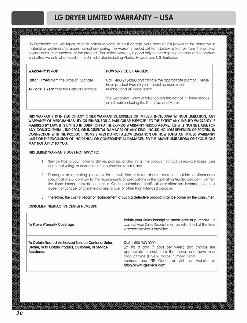
Warranty Service. The warranty for your dryer is printed the end of this manual.Warranty service is available by contacting your nearest LG Service Center and, for warranty periodfrom the date of purchase, if this dryer is installed and operated according to the instructions in thismanual, LG will repair or replace any of its mechanical or electrical parts if they are defective inmaterial or workmanship.
Warranty Restriction: If the dryer is subjected to other than private family use, all warrantycoverage is effective for only 90 days.
You will need the complete model and serial numbers when requesting information. We recommendthat you staple your sales slip or cancelled check here, because proof of original purchase date isneeded to obtain warranty service. Your dryer’s model and serial numbers are located on the Modeland Serial Number Plate located on the front of the dryer behind the door.
Use the space below to record the model number and serial number of your new LG dryer.
Model No.
Serial No.
Date of Purchase
❈ Staple your receipt hear.
!
Part 1 IMPORTANT WARRANTY AND SAFETY INSTRUCTIONS
4
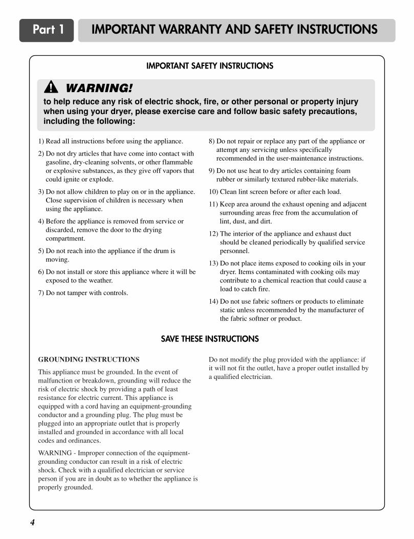
1) Read all instructions before using the appliance.
2) Do not dry articles that have come into contact withgasoline, dry-cleaning solvents, or other flammableor explosive substances, as they give off vapors thatcould ignite or explode.
3) Do not allow children to play on or in the appliance.Close supervision of children is necessary whenusing the appliance.
4) Before the appliance is removed from service ordiscarded, remove the door to the dryingcompartment.
5) Do not reach into the appliance if the drum ismoving.
6) Do not install or store this appliance where it will beexposed to the weather.
7) Do not tamper with controls.
8) Do not repair or replace any part of the appliance orattempt any servicing unless specificallyrecommended in the user-maintenance instructions.
9) Do not use heat to dry articles containing foamrubber or similarly textured rubber-like materials.
10) Clean lint screen before or after each load.
11) Keep area around the exhaust opening and adjacentsurrounding areas free from the accumulation oflint, dust, and dirt.
12) The interior of the appliance and exhaust ductshould be cleaned periodically by qualified servicepersonnel.
13) Do not place items exposed to cooking oils in yourdryer. Items contaminated with cooking oils maycontribute to a chemical reaction that could cause aload to catch fire.
14) Do not use fabric softners or products to eliminatestatic unless recommended by the manufacturer ofthe fabric softner or product.
GROUNDING INSTRUCTIONS
This appliance must be grounded. In the event ofmalfunction or breakdown, grounding will reduce therisk of electric shock by providing a path of leastresistance for electric current. This appliance isequipped with a cord having an equipment-groundingconductor and a grounding plug. The plug must beplugged into an appropriate outlet that is properlyinstalled and grounded in accordance with all localcodes and ordinances.
WARNING - Improper connection of the equipment-grounding conductor can result in a risk of electricshock. Check with a qualified electrician or serviceperson if you are in doubt as to whether the appliance isproperly grounded.
Do not modify the plug provided with the appliance: ifit will not fit the outlet, have a proper outlet installed bya qualified electrician.
WARNING!to help reduce any risk of electric shock, fire, or other personal or property injurywhen using your dryer, please exercise care and follow basic safety precautions,including the following:
!
IMPORTANT SAFETY INSTRUCTIONS
SAVE THESE INSTRUCTIONS
5
Part 1 IMPORTANT WARRANTY AND SAFETY INSTRUCTIONS
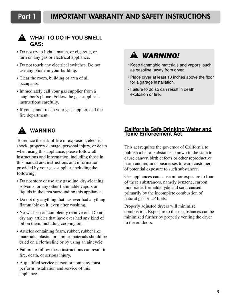
• Do not try to light a match, or cigarette, orturn on any gas or electrical appliance.
• Do not touch any electrical switches. Do notuse any phone in your building.
• Clear the room, building or area of alloccupants.
• Immediately call your gas supplier from aneighbor’s phone. Follow the gas supplier’sinstructions carefully.
• If you cannot reach your gas supplier, call thefire department.
To reduce the risk of fire or explosion, electricshock, property damage, personal injury, or deathwhen using this appliance, please follow allinstructions and information, including those inthis manual and instructions and informationprovided by your gas supplier, including thefollowing:
• Do not store or use any gasoline, dry-cleaningsolvents, or any other flammable vapors orliquids in the area surrounding this appliance.
• Do not dry anything that has ever had anythingflammable on it, even after washing.
• No washer can completely remove oil. Do notdry any articles that have ever had any kind ofoil on them, including cooking oil.
• Articles containing foam, rubber, rubber likematerials, plastic, or similar materials should bedried on a clothesline or by using an air cycle.
• Failure to follow these instructions can result infire, death, or serious injury.
• A qualified service person or company mustperform installation and service of thisappliance.
California Safe Drinking Water andToxic Enforcement Act
This act requires the governor of California topublish a list of substances known to the state tocause cancer, birth defects or other reproductiveharm and requires businesses to warn customersof potential exposure to such substances.
Gas appliances can cause minor exposure to fourof these substrances, namely benzene, carbonmonoxide, formaldehyde and soot, causedprimarily by the incomplete combustion ofnatural gas or LP fuels.
Properly adjusted dryers will minimizecombustion. Exposure to these substances can beminimized further by properly venting the dryerto the outdoors.
WHAT TO DO IF YOU SMELLGAS:
WARNING!• Keep flammable materials and vapors, such
as gasoline, away from dryer.
• Place dryer at least 18 inches above the floorfor a garage installation.
• Failure to do so can result in death,explosion or fire.
!
!
WARNING!
Part 2 INITIAL STEPS FOR INSTALLING YOUR DRYER
6
50.5"
(128.27 cm)
42"3/4(108.6 cm)
27"(68.6 cm)
30"(76.2 cm)
3"(7.6 cm)
3"(7.6 cm)
48"2
(310 cm2)
24"2
(155 cm2)
31.5"1"(2.54 cm) (80.01 cm)
1"(2.54 cm)
14" max(35.6 cm)
18" (45.72 cm)
27"(68.6 cm)
0"(0 cm)
0"(0 cm)
The following instructions will help guide you through the initial steps of setting up your dryer for use.Please note that every section of this manual provides important information regarding the preparation anduse of your dryer, and it is important that you review this entire manual before proceeding with anyinstallation or use. More detailed instructions concerning electrical connections, gas connections, andexhaust requirements are provided at other parts of this manual.
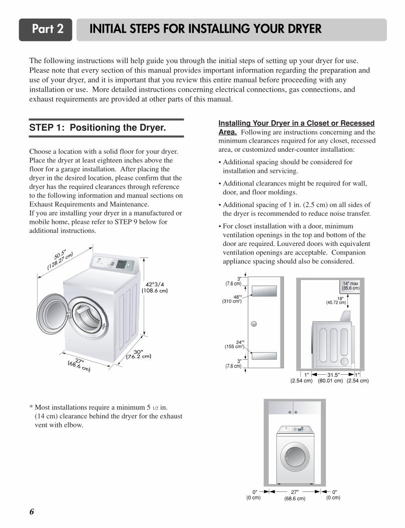
Choose a location with a solid floor for your dryer.Place the dryer at least eighteen inches above thefloor for a garage installation. After placing thedryer in the desired location, please confirm that thedryer has the required clearances through referenceto the following information and manual sections onExhaust Requirements and Maintenance. If you are installing your dryer in a manufactured ormobile home, please refer to STEP 9 below foradditional instructions.
Installing Your Dryer in a Closet or RecessedArea. Following are instructions concerning and theminimum clearances required for any closet, recessedarea, or customized under-counter installation:
• Additional spacing should be considered forinstallation and servicing.
• Additional clearances might be required for wall,door, and floor moldings.
• Additional spacing of 1 in. (2.5 cm) on all sides ofthe dryer is recommended to reduce noise transfer.
• For closet installation with a door, minimumventilation openings in the top and bottom of thedoor are required. Louvered doors with equivalentventilation openings are acceptable. Companionappliance spacing should also be considered.
* Most installations require a minimum 5 1/2 in. (14 cm) clearance behind the dryer for the exhaustvent with elbow.
STEP 1: Positioning the Dryer.

7
Part 2 INITIAL STEPS FOR INSTALLING YOUR DRYER
Once in position, adjust the leveling legs of the dryeruntil it is level from left to right and from front toback. The leveling legs must remain firmly on thefloor and the dryer should not rock. The maximumslope of the dryer from left to right or from front toback should not exceed 2.5 cm (1 inch). If the dryeris not level, and if the slope exceeds 2.5 cm (1 inch),a load may not tumble properly and internal sensorsmay malfunction. Note: Other sections of thismanual also provide important informationconcerning the placement of and clearances for yourdryer. Please review this entire manual beforeproceeding with any installation.
The door on your dryer may be installed to openeither to the left or the right. Follow theseprocedures to reverse the direction in which yourdoor opens:
STEP 2: Procedure for Reversingthe Door
1
2
3
Part 2 INITIAL STEPS FOR INSTALLING YOUR DRYER
8
In addition to the following warnings, please referto manual section on Exhaust Requirements andMaintenance. IMPORTANT: To reduce the risk offire, combustion, and gas accumulation, the dryermust be vented to the outdoors. Please follow thefollowing instructions (and all others in thismanual) very carefully.
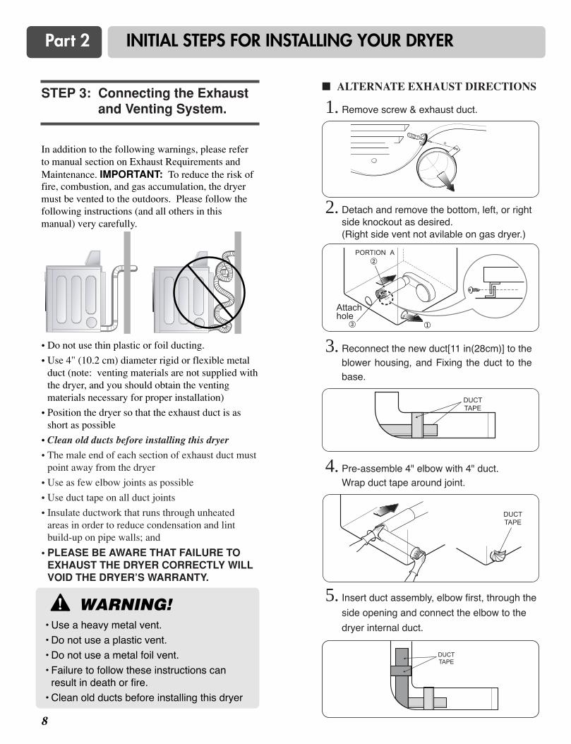
• Do not use thin plastic or foil ducting.
• Use 4" (10.2 cm) diameter rigid or flexible metalduct (note: venting materials are not supplied withthe dryer, and you should obtain the ventingmaterials necessary for proper installation)
• Position the dryer so that the exhaust duct is asshort as possible
• Clean old ducts before installing this dryer
• The male end of each section of exhaust duct mustpoint away from the dryer
• Use as few elbow joints as possible
• Use duct tape on all duct joints
• Insulate ductwork that runs through unheatedareas in order to reduce condensation and lintbuild-up on pipe walls; and
• PLEASE BE AWARE THAT FAILURE TOEXHAUST THE DRYER CORRECTLY WILLVOID THE DRYER’S WARRANTY.
STEP 3: Connecting the Exhaustand Venting System.
WARNING!• Use a heavy metal vent.
• Do not use a plastic vent.
• Do not use a metal foil vent.
• Failure to follow these instructions can result in death or fire.
• Clean old ducts before installing this dryer
!
� ALTERNATE EXHAUST DIRECTIONS
1. Remove screw & exhaust duct.
2. Detach and remove the bottom, left, or rightside knockout as desired.(Right side vent not avilable on gas dryer.)
3. Reconnect the new duct[11 in(28cm)] to theblower housing, and Fixing the duct to thebase.
4. Pre-assemble 4" elbow with 4" duct. Wrap duct tape around joint.
5. Insert duct assembly, elbow first, through the
side opening and connect the elbow to the
dryer internal duct.
Attachhole
9
Part 2 INITIAL STEPS FOR INSTALLING YOUR DRYER
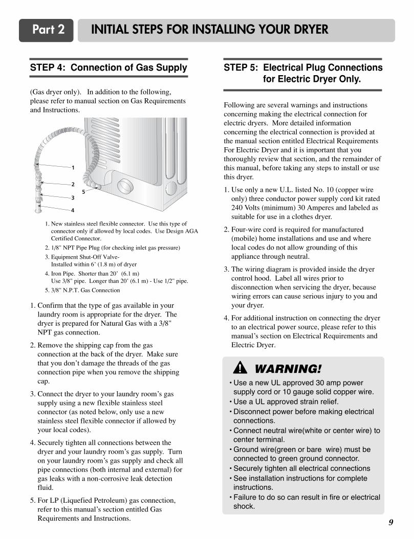
(Gas dryer only). In addition to the following,please refer to manual section on Gas Requirementsand Instructions.
1. Confirm that the type of gas available in yourlaundry room is appropriate for the dryer. Thedryer is prepared for Natural Gas with a 3/8"NPT gas connection.
2. Remove the shipping cap from the gasconnection at the back of the dryer. Make surethat you don’t damage the threads of the gasconnection pipe when you remove the shippingcap.
3. Connect the dryer to your laundry room’s gassupply using a new flexible stainless steelconnector (as noted below, only use a newstainless steel flexible connector if allowed byyour local codes).
4. Securely tighten all connections between thedryer and your laundry room’s gas supply. Turnon your laundry room’s gas supply and check allpipe connections (both internal and external) forgas leaks with a non-corrosive leak detectionfluid.
5. For LP (Liquefied Petroleum) gas connection,refer to this manual’s section entitled GasRequirements and Instructions.
1. New stainless steel flexible connector. Use this type ofconnector only if allowed by local codes. Use Design AGACertified Connector.
2. 1/8" NPT Pipe Plug (for checking inlet gas pressure)
3. Equipment Shut-Off Valve-Installed within 6’ (1.8 m) of dryer
4. Iron Pipe. Shorter than 20’ (6.1 m)Use 3/8" pipe. Longer than 20’ (6.1 m) - Use 1/2" pipe.
5. 3/8" N.P.T. Gas Connection
STEP 4: Connection of Gas Supply
Following are several warnings and instructionsconcerning making the electrical connection forelectric dryers. More detailed informationconcerning the electrical connection is provided atthe manual section entitled Electrical RequirementsFor Electric Dryer and it is important that youthoroughly review that section, and the remainder ofthis manual, before taking any steps to install or usethis dryer.
1. Use only a new U.L. listed No. 10 (copper wireonly) three conductor power supply cord kit rated240 Volts (minimum) 30 Amperes and labeled assuitable for use in a clothes dryer.
2. Four-wire cord is required for manufactured(mobile) home installations and use and wherelocal codes do not allow grounding of thisappliance through neutral.
3. The wiring diagram is provided inside the dryercontrol hood. Label all wires prior todisconnection when servicing the dryer, becausewiring errors can cause serious injury to you andyour dryer.
4. For additional instruction on connecting the dryerto an electrical power source, please refer to thismanual’s section on Electrical Requirements andElectric Dryer.
STEP 5: Electrical Plug Connectionsfor Electric Dryer Only.
2
35
1
4
WARNING!• Use a new UL approved 30 amp power
supply cord or 10 gauge solid copper wire.• Use a UL approved strain relief.• Disconnect power before making electrical
connections.• Connect neutral wire(white or center wire) to
center terminal. • Ground wire(green or bare wire) must be
connected to green ground connector.• Securely tighten all electrical connections• See installation instructions for complete
instructions.• Failure to do so can result in fire or electrical
shock.
!
Part 2 INITIAL STEPS FOR INSTALLING YOUR DRYER
1 0
Prior to first use of this appliance, use an all-purpose cleaning product, or a solution of detergentand water, with a damp clothe to remove from theinside of the dryer drum/drying compartment anydust or dirt that may have accumulated inside of thedryer. Plug in your dryer after reviewing thefollowing parts on your dryer’s ElectricalRequirements.
STEP 6: Preparation of the Dryer.
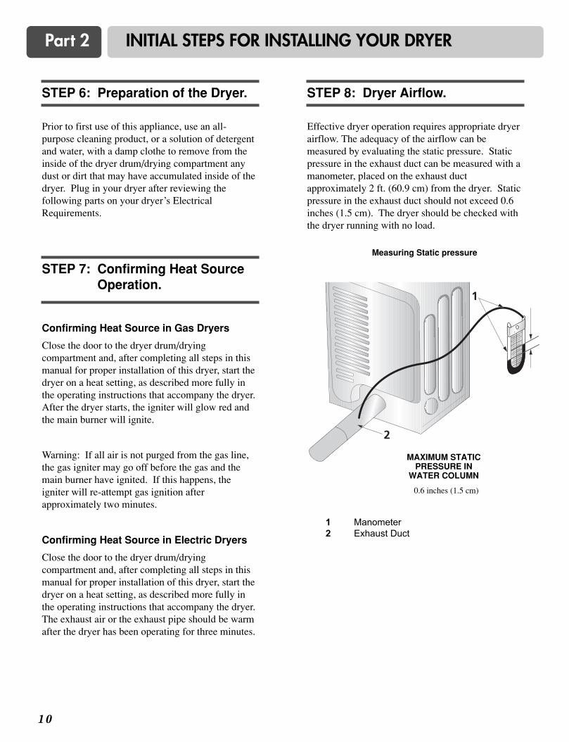
Effective dryer operation requires appropriate dryerairflow. The adequacy of the airflow can bemeasured by evaluating the static pressure. Staticpressure in the exhaust duct can be measured with amanometer, placed on the exhaust ductapproximately 2 ft. (60.9 cm) from the dryer. Staticpressure in the exhaust duct should not exceed 0.6inches (1.5 cm). The dryer should be checked withthe dryer running with no load.
STEP 8: Dryer Airflow.
Confirming Heat Source in Gas Dryers
Close the door to the dryer drum/dryingcompartment and, after completing all steps in thismanual for proper installation of this dryer, start thedryer on a heat setting, as described more fully inthe operating instructions that accompany the dryer.After the dryer starts, the igniter will glow red andthe main burner will ignite.
Warning: If all air is not purged from the gas line,the gas igniter may go off before the gas and themain burner have ignited. If this happens, theigniter will re-attempt gas ignition afterapproximately two minutes.
Confirming Heat Source in Electric Dryers
Close the door to the dryer drum/dryingcompartment and, after completing all steps in thismanual for proper installation of this dryer, start thedryer on a heat setting, as described more fully inthe operating instructions that accompany the dryer.The exhaust air or the exhaust pipe should be warmafter the dryer has been operating for three minutes.
STEP 7: Confirming Heat SourceOperation.
1
2
Measuring Static pressure
0.6 inches (1.5 cm)
MAXIMUM STATIC PRESSURE IN
WATER COLUMN
1 Manometer2 Exhaust Duct

1 1
Part 2 INITIAL STEPS FOR INSTALLING YOUR DRYER
The following instructions are applicable toinstallations of the dryer in a manufactured ormobile home. Any installation in a manufactured ormobile home must comply with the ManufacturedHome Construction and Safety Standards Title 24CFR, Part 32-80 or Standard CAN/CSA0Z240 MHand local codes and ordinances. If you areuncertain whether your proposed installation willcomply with these standards, please contact aservice and installation professional for assistance.
The following instructions apply to any installationof the dryer in a manufactured or mobile home:
1) The gas dryer must be permanently attached tothe floor.
2) The electrical connection for an electric dryermust be a 4-wire connection. More detailedinformation concerning the electrical connectionis provided at the manual section entitledElectrical Requirements for Electric Dryer
3) To reduce the risk of combustion and fire, thedryer must be vented to the outside.
4) Electric dryers may be vented to the outsideusing the back, left, right, or bottom panel.
5) Gas dryers may be vented to the outside using theback, left, or bottom panel. Gas dryer may not bevented to the outside using the right side panelbecause of the burner housing.
6) The dryer exhaust duct must be affixed securelyto the manufactured or mobile home structure,and the exhaust duct must be made of a materialthat will resist fire and combustion, and it isrecommended that you use a rigid or flexiblemetal pipe.
7) DO NOT connect the exhaust duct with any otherduct, vent, chimney, or other exhaust duct.
8) Make sure the dryer has adequate access tooutside fresh air to ensure proper operation. Theopening for outside fresh air must be at least 25in2 (163 cm2).
9) It is important that the clearance of the duct fromany combustible construction be at least 2 inches(5 cm), and, when venting the dryer to theoutdoors, the dryer can be installed with aclearances of 1 inch at the sides and back of thedryer.
10) Please be aware that venting materials are notsupplied with the dryer. You should obtain theventing materials necessary for properinstallation.
STEP 9: Additional Instructions forInstallation of Your Dryerin a Manufactured orMobile Home.
WARNING!DO NOT connect exhaust ducts with metal screws or fasteners that extend into the duct.
! WARNING!DO NOT vent the exhaust duct under themanufactured or mobile home.
!
Part 3 ELECTRICAL REQUIREMENTS FOR ELECTRIC DRYERS
1 2
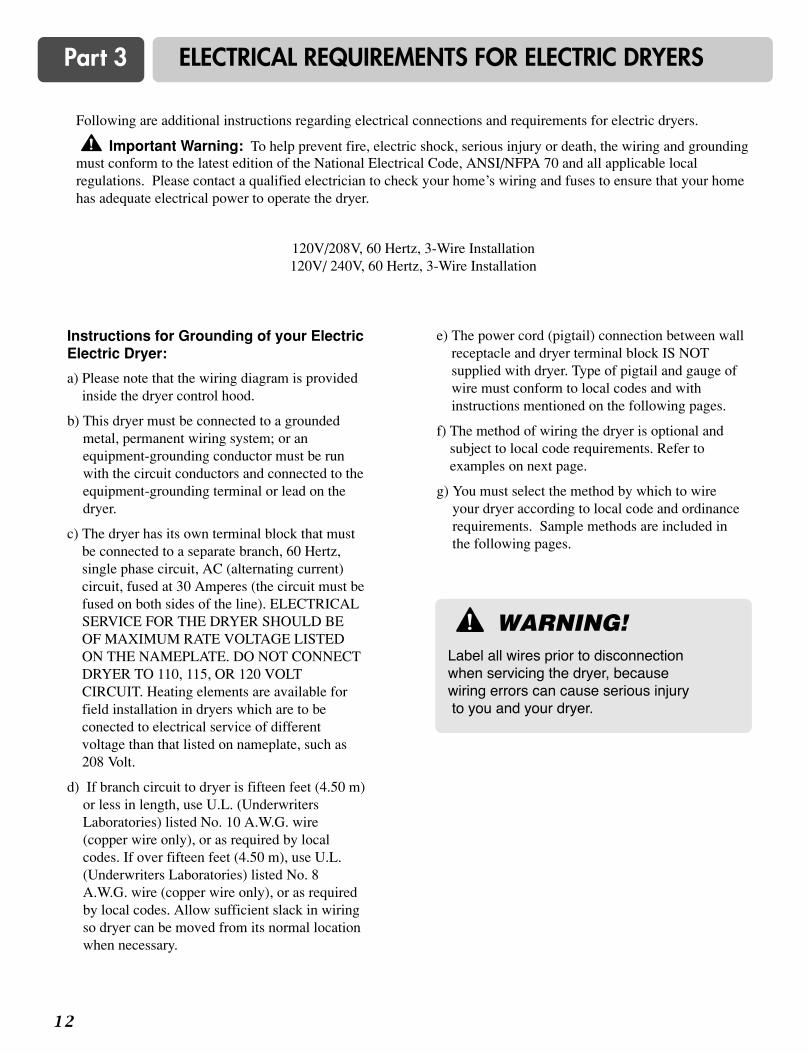
Following are additional instructions regarding electrical connections and requirements for electric dryers.
Important Warning: To help prevent fire, electric shock, serious injury or death, the wiring and groundingmust conform to the latest edition of the National Electrical Code, ANSI/NFPA 70 and all applicable localregulations. Please contact a qualified electrician to check your home’s wiring and fuses to ensure that your homehas adequate electrical power to operate the dryer.
120V/208V, 60 Hertz, 3-Wire Installation120V/ 240V, 60 Hertz, 3-Wire Installation
!
Instructions for Grounding of your ElectricElectric Dryer:
a) Please note that the wiring diagram is providedinside the dryer control hood.
b) This dryer must be connected to a groundedmetal, permanent wiring system; or anequipment-grounding conductor must be runwith the circuit conductors and connected to theequipment-grounding terminal or lead on thedryer.
c) The dryer has its own terminal block that mustbe connected to a separate branch, 60 Hertz,single phase circuit, AC (alternating current)circuit, fused at 30 Amperes (the circuit must befused on both sides of the line). ELECTRICALSERVICE FOR THE DRYER SHOULD BEOF MAXIMUM RATE VOLTAGE LISTEDON THE NAMEPLATE. DO NOT CONNECTDRYER TO 110, 115, OR 120 VOLTCIRCUIT. Heating elements are available forfield installation in dryers which are to beconected to electrical service of differentvoltage than that listed on nameplate, such as208 Volt.
d) If branch circuit to dryer is fifteen feet (4.50 m)or less in length, use U.L. (UnderwritersLaboratories) listed No. 10 A.W.G. wire(copper wire only), or as required by localcodes. If over fifteen feet (4.50 m), use U.L.(Underwriters Laboratories) listed No. 8A.W.G. wire (copper wire only), or as requiredby local codes. Allow sufficient slack in wiringso dryer can be moved from its normal locationwhen necessary.
e) The power cord (pigtail) connection between wallreceptacle and dryer terminal block IS NOTsupplied with dryer. Type of pigtail and gauge ofwire must conform to local codes and withinstructions mentioned on the following pages.
f) The method of wiring the dryer is optional andsubject to local code requirements. Refer toexamples on next page.
g) You must select the method by which to wireyour dryer according to local code and ordinancerequirements. Sample methods are included inthe following pages.
WARNING!Label all wires prior to disconnection when servicing the dryer, because wiring errors can cause serious injuryto you and your dryer.
!

1 3
Part 3 ELECTRICAL REQUIREMENTS FOR ELECTRIC DRYERS
Use the instructions at this section if your home hasa 3-wire receptacle (NEMA type 10-30R) and youwill be using a UL listed, 120/240 volt minimum,30 amp, dryer power supply cord.
Review the following options to determine the appropriate electrical connectionfor your home:
Important: If your local codes or ordinances do not allow the connection of a frame-grounding conductor to the neutral wire, use the instructions under Option 3: Optional 3-wire connection.
3-wire receptacle (NEMA type10-30R)
Use the instructions at this section if your home hasa 4-wire receptacle (NEMA type 14-30R) and youwill be using a UL listed, 120/240 volt minimum,30 amp, dryer power supply cord.
4-wire receptacle (NEMA type14-30R)

Part 3 ELECTRICAL REQUIREMENTS FOR ELECTRIC DRYERS
1 4
a. 3-wire receptacle (NEMA type 10-30R)b. 3-wire plugc. Neutral prongd. Spade terminals with up turned endse. 3/4 in. (1.9 cm) UL approved strain relieff. Ring terminalsg. Neutral (white or center wire)
a. External ground connectorb. Neutral grounding wire (green)c. Center silver-colored terminal block screwd. Neutral wire (white or center wire)e. 3/4 in. (1.9 cm) UL-listed strain relief
1. Loosen or remove center terminal block screw.
2. Connect neutral wire (white or center wire) ofpower supply cord to the center, silver coloredterminal screw of the terminal block. Tightenscrew.
3. Connect the other wires to outer terminal blockscrews. Tighten screws.
4. Tighten strain relief screws.
5. Insert tab of terminal block cover into slot ofdryer rear panel. Secure cover with hold-downscrew.
d
g f
a
lf your local codes or ordinances permit theconnection of a frame-grounding conductor to theneutral wire, use these instructions. If your localcodes or ordinances do not allow the connection ofa frame-grounding conductor to the neutral wire,use the instructions under Section 3: Optional3-wire connection.
Option 1: 3-Wire Connection witha Power Supply Cord

1 5
Part 3 ELECTRICAL REQUIREMENTS FOR ELECTRIC DRYERS
a. 4-wire receptable (NEMA type 14-30R)b. 4-pront plugc. Ground prongd. Neutral Pronge. Spade terminals with upturned endsf. 3/4 in. (1.9 cm) UL approved strain reliefg. Ring terminals
a. External ground connector - Dotted lineshows position of NEUTRAL ground wirebefore being moved to center terminal blockscrew
b. Center silver-colored terminal block screwc. Green wire of harness
1. Remove center terminal block screw.
2. Remove appliance ground wire (green) fromexternal ground connector screw. Fasten it underthe center, silver colored terminal block screw.
3. Connect ground wire (green or bare) of powersupply cable to external ground conductor screw.Tighten screw.
4. Connect neutral wire (white or center wire) ofpower supply cord to the center, silver coloredterminal screw of the terminal block.
a. External ground connectorb. Green or bare copper wire of power supply cordc. 3/4 in. (1.9 cm) UL-listed strain reliefd. Center silver-colored terminal block screwe. Neutral grounding wire (green)f. Neutral wire (white)
5. Connect the other wires to outer terminal blockscrews. Tighten screws.
6. Tighten strain relief screws.
7. Insert tab of terminal block cover into slot ofdryer rear panel. Secure cover with hold-downscrew.
• lf your local codes or ordinances do not allow theuse of a 3 wire connection, or you are installingyour dryer in a mobile home, you must use a 4-wire connection.
Option 2: 4-wire connection with aPower supply cord.
1 6
Part 3 ELECTRICAL REQUIREMENTS FOR ELECTRIC DRYERS
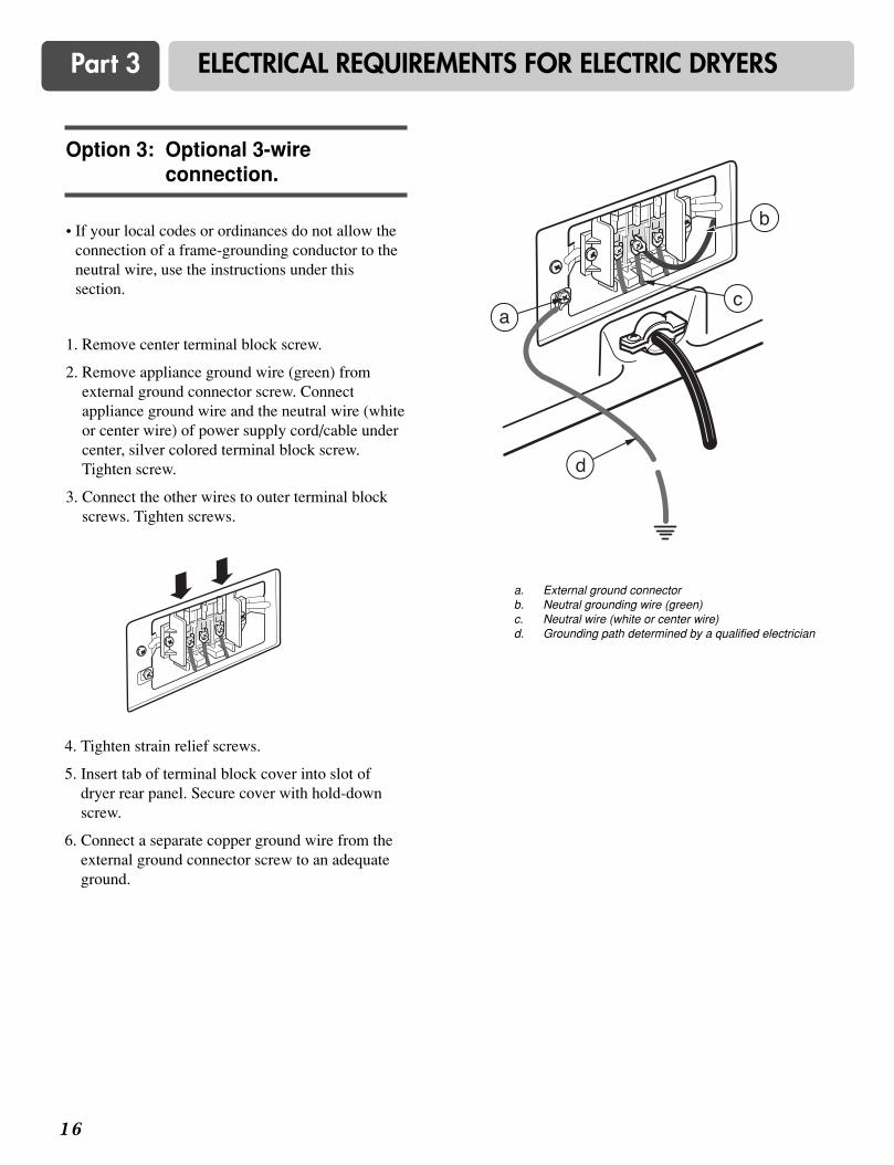
• If your local codes or ordinances do not allow theconnection of a frame-grounding conductor to theneutral wire, use the instructions under thissection.
1. Remove center terminal block screw.
2. Remove appliance ground wire (green) fromexternal ground connector screw. Connectappliance ground wire and the neutral wire (whiteor center wire) of power supply cord/cable undercenter, silver colored terminal block screw.Tighten screw.
3. Connect the other wires to outer terminal blockscrews. Tighten screws.
4. Tighten strain relief screws.
5. Insert tab of terminal block cover into slot ofdryer rear panel. Secure cover with hold-downscrew.
6. Connect a separate copper ground wire from theexternal ground connector screw to an adequateground.
Option 3: Optional 3-wireconnection.
a. External ground connectorb. Neutral grounding wire (green)c. Neutral wire (white or center wire)d. Grounding path determined by a qualified electrician
1 7
Part 4 ELECTRICAL REQUIREMENTS FOR GAS DRYERS
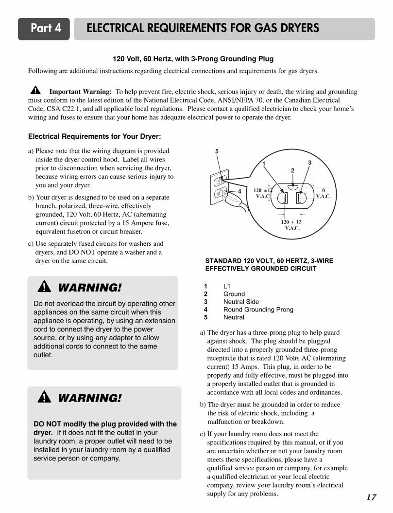
120 Volt, 60 Hertz, with 3-Prong Grounding Plug
Following are additional instructions regarding electrical connections and requirements for gas dryers.
Important Warning: To help prevent fire, electric shock, serious injury or death, the wiring and groundingmust conform to the latest edition of the National Electrical Code, ANSI/NFPA 70, or the Canadian ElectricalCode, CSA C22.1, and all applicable local regulations. Please contact a qualified electrician to check your home’swiring and fuses to ensure that your home has adequate electrical power to operate the dryer.
Electrical Requirements for Your Dryer:
!
a) Please note that the wiring diagram is providedinside the dryer control hood. Label all wiresprior to disconnection when servicing the dryer,because wiring errors can cause serious injury toyou and your dryer.
b) Your dryer is designed to be used on a separatebranch, polarized, three-wire, effectivelygrounded, 120 Volt, 60 Hertz, AC (alternatingcurrent) circuit protected by a 15 Ampere fuse,equivalent fusetron or circuit breaker.
c) Use separately fused circuits for washers anddryers, and DO NOT operate a washer and adryer on the same circuit.
a) The dryer has a three-prong plug to help guardagainst shock. The plug should be pluggeddirected into a properly grounded three-prongreceptacle that is rated 120 Volts AC (alternatingcurrent) 15 Amps. This plug, in order to beproperly and fully effective, must be plugged intoa properly installed outlet that is grounded inaccordance with all local codes and ordinances.
b) The dryer must be grounded in order to reducethe risk of electric shock, including amalfunction or breakdown.
c) If your laundry room does not meet thespecifications required by this manual, or if youare uncertain whether or not your laundry roommeets these specifications, please have aqualified service person or company, for examplea qualified electrician or your local electriccompany, review your laundry room’s electricalsupply for any problems.
WARNING!Do not overload the circuit by operating otherappliances on the same circuit when thisappliance is operating, by using an extensioncord to connect the dryer to the powersource, or by using any adapter to allowadditional cords to connect to the sameoutlet.
!
STANDARD 120 VOLT, 60 HERTZ, 3-WIREEFFECTIVELY GROUNDED CIRCUIT
1 L12 Ground3 Neutral Side4 Round Grounding Prong5 Neutral
21 3
5
4
V.A.C.120 + 12
0 V.A.C.
120 ± 12 V.A.C
WARNING!
DO NOT modify the plug provided with thedryer. If it does not fit the outlet in yourlaundry room, a proper outlet will need to beinstalled in your laundry room by a qualifiedservice person or company.
!

1 8
Part 5 GAS REQUIREMENTS AND INSTRUCTIONS
Following are important instructions and information concerning the requirements for the gas supply and service forgas dryers. Important Warning: The gas supply and service for a gas dryer must comply with all local codesand ordinances. In the absence of any local codes or ordinances in your area, the gas supply and service for your gasdryer must comply with the latest edition of the National Fuel Cas Code, ANSI Z223.1/NFPA 54.
1. Gas supply requirements: Liquefied Petroleum(L.P.) Gas (2,500 Btu/ft3 (93.1 MJ/m3)) servicemust be provided at 10 + 1.5 in. water columnpressure.
2. Important: DO NOT connect the dryer to theLiquefied Petroleum (LP) Gas service withoutconverting the gas value.
3. A qualified technician must perform the LP Gasconversion. Contact your local gas service branchif you require additional assistance orinformation.
4. Isolate the dryer from the gas supply pipingsystem by closing its individual manual shut-offvalve, during any pressure testing of the gassupply system at test pressure equal to or lessthan 2/1 psi (3.45 kPa).
5. Supply Line Requirements. Your laundry roommust have a rigid gas supply line to your dryer.In the United States, an individual manual shutoffvalve MUST be installed within at least 6 feet(1.8m) of the dryer, in accordance with theNational Fuel Gas Coide ANSI Z223.1. A 1/8 in.N.P.T. pipe plug must be installed as shown.
6. If using a rigid pipe, the rigid pipe should be 1/2inch IPS. If acceptable under local codes andordinances and when acceptable to your gassupplier, 3/8 inch approved tubing may be usedwhere lengths are less than 20 feet (6.1m).Larger tubing should be used for lengths inexcess of 20 feet (6.1m). It is also important thatyou use pipe joint compound that is insoluble inLP gas.
7. To reduce the danger of gas leaks, explosion, andfire, please follow and observe the followinginstructions and WARNINGS:
• Connect the dryer to the type of gas shown on thenameplate;
• Use new flexible stainless steel connectors;
• Use Teflon tape and pipe joint compoundinsoluble in LP gas on all pipe threads;
• Purge gas supply of air and sediment beforeconnecting the gas supply to the dryer; in order toprevent gas valve contamination, before tighteningconnection between gas supply and dryer, purgeremaining air until odor of gas is identified; and
• DO NOT use an open flame to inspect for gasleaks; instead, use a non-corrosive leak detectionfluid.
WARNING!• Use a new AGA or CSA approved gas
supply line.
• Install a shut-off valve.
• Securely tighten all gas connections.
• If connected to LP, have a qualified personmake sure gas pressure does not exceed 13 in. water column.
• Examples of a qualified person includelicensed heating personnel, authorized gascompany personnel, and authorized servicepersonnel.
• Failure to do so can result in death,explosion, or fire.
!WARNING!
DO NOT attempt any disassembly of thedryer, any disassembly requires theattention and tools of an authorized andqualified service person or company.
!
!
1 9
Part 6 EXHAUST REQUIREMENTS AND MAINTENANCE
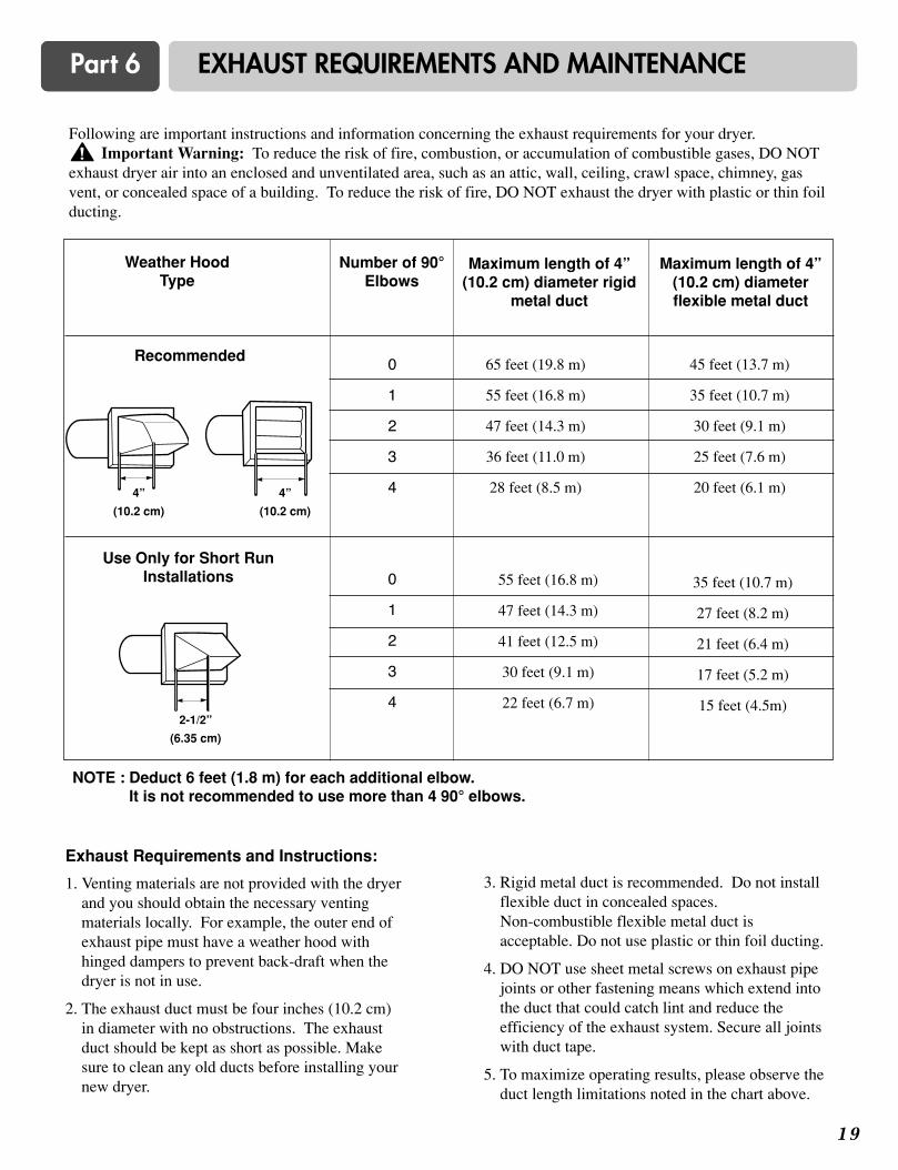
Following are important instructions and information concerning the exhaust requirements for your dryer. Important Warning: To reduce the risk of fire, combustion, or accumulation of combustible gases, DO NOT
exhaust dryer air into an enclosed and unventilated area, such as an attic, wall, ceiling, crawl space, chimney, gasvent, or concealed space of a building. To reduce the risk of fire, DO NOT exhaust the dryer with plastic or thin foilducting.
Exhaust Requirements and Instructions:
1. Venting materials are not provided with the dryerand you should obtain the necessary ventingmaterials locally. For example, the outer end ofexhaust pipe must have a weather hood withhinged dampers to prevent back-draft when thedryer is not in use.
2. The exhaust duct must be four inches (10.2 cm)in diameter with no obstructions. The exhaustduct should be kept as short as possible. Makesure to clean any old ducts before installing yournew dryer.
3. Rigid metal duct is recommended. Do not installflexible duct in concealed spaces. Non-combustible flexible metal duct isacceptable. Do not use plastic or thin foil ducting.
4. DO NOT use sheet metal screws on exhaust pipejoints or other fastening means which extend intothe duct that could catch lint and reduce theefficiency of the exhaust system. Secure all jointswith duct tape.
5. To maximize operating results, please observe theduct length limitations noted in the chart above.
!
Number of 90°Elbows
Weather HoodType
Recommended
Maximum length of 4”(10.2 cm) diameter rigid
metal duct
Maximum length of 4”(10.2 cm) diameterflexible metal duct
NOTE : Deduct 6 feet (1.8 m) for each additional elbow. It is not recommended to use more than 4 90° elbows.
Use Only for Short RunInstallations
0
1
2
3
4
0
1
2
3
4
65 feet (19.8 m)
55 feet (16.8 m)
47 feet (14.3 m)
36 feet (11.0 m)
28 feet (8.5 m)
45 feet (13.7 m)
35 feet (10.7 m)
30 feet (9.1 m)
25 feet (7.6 m)
20 feet (6.1 m)
55 feet (16.8 m)
47 feet (14.3 m)
41 feet (12.5 m)
30 feet (9.1 m)
22 feet (6.7 m)
35 feet (10.7 m)
27 feet (8.2 m)
21 feet (6.4 m)
17 feet (5.2 m)
15 feet (4.5m)
4”
(10.2 cm)
4”
(10.2 cm)
2-1/2”
(6.35 cm)
2 0
Part 6 EXHAUST REQUIREMENTS AND MAINTENANCE
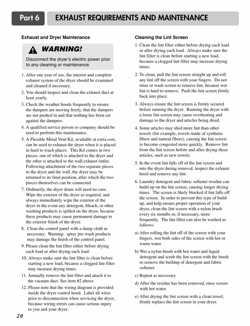
Exhaust and Dryer Maintenance
1. After one year of use, the interior and completeexhaust system of the dryer should be examinedand cleaned if necessary.
2. You should inspect and clean the exhaust duct atleast yearly.
3. Check the weather hoods frequently to ensurethe dampers are moving freely, that the dampersare not pushed in and that nothing has been setagainst the dampers.
4. A qualified service person or company should beused to perform this maintenance.
5. A Flexible Metal Vent Kit, available at extra cost,can be used to exhaust the dryer when it is placedin hard to reach places. This Kit comes in twopieces, one of which is attached to the dryer andthe other is attached to the wall exhaust outlet.Following attachment of the two separate piecesto the dryer and the wall, the dryer may bereturned to its final position, after which the twopieces themselves can be connected.
7. Ordinarily, the dryer drum will need no care.Wipe the exterior of the dryer as required, andalways immediately wipe the exterior of thedryer in the event any detergent, bleach, or otherwashing products is spilled on the dryer, becausethese products may cause permanent damage tothe exterior finish of the dryer.
8. Clean the control panel with a damp cloth asnecessary. Warning: spray pre-wash productsmay damage the finish of the control panel.
9. Please clean the lint filter either before dryingeach load or after drying each load.
10. Always make sure the lint filter is clean beforestarting a new load, because a clogged lint filtermay increase drying times.
11. Annually remove the lint filter and attach it tothe vacuum duct. See item #2 above.
12. Please note that the wiring diagram is providedinside the dryer control hood. Label all wiresprior to disconnection when servicing the dryer,because wiring errors can cause serious injuryto you and your dryer.
Cleaning the Lint Screen
1. Clean the lint filter either before drying each loador after drying each load. Always make sure thelint filter is clean before starting a new load,because a clogged lint filter may increase dryingtimes.
2. To clean, pull the lint screen straight up and rollany lint off the screen with your fingers. Do notrinse or wash screen to remove lint, because wetlint is hard to remove. Push the lint screen firmlyback into place.
3. Always ensure the lint screen is firmly securedbefore running the dryer. Running the dryer witha loose lint screen may cause overheating anddamage to the dryer and articles being dried.
4. Some articles may shed more lint than othertowels (for example, towels made of syntheticfibers and natural fibers), causing the lint screento become congested more quickly. Remove lintfrom the lint screen before and after drying thesearticles, such as new towels.
5. In the event lint falls off of the lint screen andinto the dryer during removal, inspect the exhausthood and remove any lint.
6. Laundry detergent and fabric softener residue canbuild up on the lint screen, causing longer dryingtimes. The screen is likely blocked if lint falls offthe screen. In order to prevent this type of buildup, and help ensure proper operation of yourdryer, clean the lint screen with a nylon brushevery six months or, if necessary, morefrequently. The lint filter can also be washed asfollows:
a) After rolling the lint off of the screen with yourfingers, wet both sides of the screen with hot orwarm water.
b) Wet a nylon brush with hot water and liquiddetergent and scrub the lint screen with the brushto remove the buildup of detergent and fabricsoftener.
c) Repeat as necessary.
d) After the residue has been removed, rinse screenwith hot water.
e) After drying the lint screen with a clean towel,firmly replace the lint screen in your dryer.
WARNING!Disconnect the dryer’s electric power priorto any cleaning or maintenance.
!

2 1
Part 7 FEATURES AND BENEFITS
� DLE5911W / DLG5911W
� DLE2511W / DLG2511W
Following are instructions for starting and using your new dryer. Please refer to specific sections of this manual formore detailed information. Important Warning: To reduce the risk of fire, electric shock, or injury to person, readthis entire manual, including the Important Safety Instructions, before operating this dryer.
WARNING!
Fire Hazard
No washer can completely remove oil.
Do not dry anything that has ever had anytype of oil on it (including cooking oils).
Items containing foam, rubber, or plasticmust be dried on a clothesline or by using
an Air Cycle. Failure to follow theseinstructions can result in death or fire.
! WARNING!
Explosion Hazard
Keep flammable materials and vapors, suchas gasoline, away from dryer.
Do not dry anything that has ever hadanything flammable on it (even after washing).
Failure to follow these instructions can resultin death, explosion, or fire.
!
2 2
Part 7 FEATURES AND BENEFITS
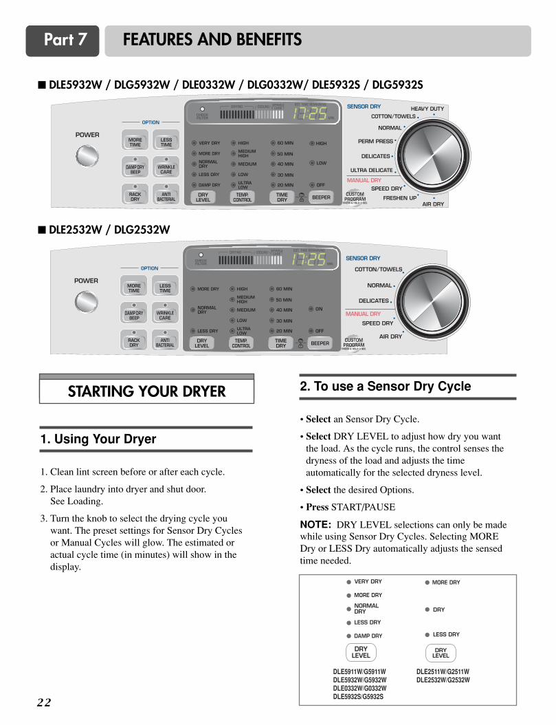
� DLE5932W / DLG5932W / DLE0332W / DLG0332W/ DLE5932S / DLG5932S
� DLE2532W / DLG2532W
STARTING YOUR DRYER
1. Clean lint screen before or after each cycle.
2. Place laundry into dryer and shut door. See Loading.
3. Turn the knob to select the drying cycle youwant. The preset settings for Sensor Dry Cyclesor Manual Cycles will glow. The estimated oractual cycle time (in minutes) will show in thedisplay.
1. Using Your Dryer
• Select an Sensor Dry Cycle.
• Select DRY LEVEL to adjust how dry you wantthe load. As the cycle runs, the control senses thedryness of the load and adjusts the timeautomatically for the selected dryness level.
• Select the desired Options.
• Press START/PAUSE
NOTE: DRY LEVEL selections can only be madewhile using Sensor Dry Cycles. Selecting MOREDry or LESS Dry automatically adjusts the sensedtime needed.
2. To use a Sensor Dry Cycle
DLE5911W/G5911WDLE5932W/G5932WDLE0332W/G0332WDLE5932S/G5932S
DLE2511W/G2511WDLE2532W/G2532W
2 3
Part 7 FEATURES AND BENEFITS
• Select a Manual Dry Cycle.
• Press MORE TIME or LESS TIME until thedesired drying time is displayed. Tap MORETIME or LESS TIME and the time will change by1 minute intervals. NOTE: The MORE TIME or LESS TIMEfeature can be used with Manual Dry, Time Dry,and Rack Dry Cycles.
• Press TEMP. CONTROL until the desiredtemperature indicator glows.
• (OPTIONAL STEP) If desired, select OPTIONS.For more details, see Options.
• Press START/PAUSE. Be sure the door is closed.
• If you do not press START/PAUSE within 10minutes of selecting the cycle, the dryerautomatically shuts off.
• If you wish to end your drying cycle after pressingSTART/PAUSE, press START/PAUSE again.
3. To use a Manual Dry Cycle
Properly loading your dryer can lower your utilitybill and prolong the life of your garments.
Loading suggestions
Load the dryer by the amount of space items takeup, not by their weight.
Do not overload the dryer. This causes unevendrying and wrinkling.
Heavy Work Clothes4 jeans4 workpants4 work shirts
2 sweatpants2 sweatshirts
Towels10 bath towels10 hand towels
14 wash cloths
Mixed Load3 sheets (1 king, 2 twin)4 pillowcases3 shirts3 blouses
9 T-shirts9 shorts10 handkerchiefs
Following are sample loads for Super CapacityDryers:
5. Loading
To stop your dryer at any time
Press START/PAUSE or open the door.
Pausing or Restarting
To pause the dryer at any time
Open the door or press START/PAUSE once.
To restart the dryer
Close the door. Press START/PAUSE.
NOTE: Drying will continue from where the cyclewas interrupted if you close the door and pressSTART within 10 minutes. If the cycle isinterrupted for more than 10 minutes, the dryer willshut off. Select new cycle settings before restartingthe dryer.
Child Lock
This feature allows you to lock your settings toprevent children from changing them. You can alsouse the child lock feature to prevent unintendedcycle or option changes during dryer operation.
To enable the Child Lock feature:
Press and hold RACK DRY and ANTIBACTERIAL for 2 seconds. A single BEEP Tone isheard, and CL is displayed. To unlock, press andhold RACK DRY and ANTI BACTERIAL for 2seconds. The indicator light turns off.
4. Stopping Your Dryer
2 4
Part 7 FEATURES AND BENEFITS
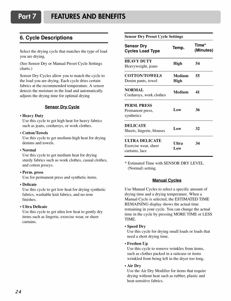
Select the drying cycle that matches the type of loadyou are drying.
(See Sensor Dry or Manual Preset Cycle Settingscharts.)
Sensor Dry Cycles allow you to match the cycle tothe load you are drying. Each cycle dries certainfabrics at the recommended temperature. A sensordetects the moisture in the load and automaticallyadjusts the drying time for optimal drying
• Heavy DutyUse this cycle to get high heat for heavy fabricssuch as jeans, corduroys, or work clothes.
• Cotton/TowelsUse this cycle to get medium-high heat for dryingdenims and towels.
• NormalUse this cycle to get medium heat for dryingsturdy fabrics such as work clothes, casual clothes,and cotton jerseys.
• Perm. pressUse for permanent press and synthetic items.
• DelicateUse this cycle to get low heat for drying syntheticfabrics, washable knit fabrics, and no-ironfinishes.
• Ultra DelicateUse this cycle to get ultra low heat to gently dryitems such as lingerie, exercise wear, or sheercurtains.
* Estimated Time with SENSOR DRY LEVEL(Normal) setting.
Sensor DryCycles Load Type
Temp.
High
MediumHigh
Medium
Low
Low
UltraLow
Time*(Minutes)
54
55
41
36
32
34
Sensor Dry Cycle
Use Manual Cycles to select a specific amount ofdrying time and a drying temperature. When aManual Cycle is selected, the ESTIMATED TIMEREMAINING display shows the actual timeremaining in your cycle. You can change the actualtime in the cycle by pressing MORE TIME or LESSTIME.
• Speed DryUse this cycle for drying small loads or loads thatneed a short drying time.
• Freshen UpUse this cycle to remove wrinkles from items,such as clothes packed in a suitcase or itemswrinkled from being left in the dryer too long.
• Air DryUse the Air Dry Modifier for items that requiredrying without heat such as rubber, plastic andheat-sensitive fabrics.
Manual Cycles
HEAVY DUTYHeavyweight, jeans
COTTON/TOWELSDenim pants, towel
NORMALCorduroys, work clothes
PERM. PRESSPermanent press,synthetics
DELICATESheets, lingerie, blouses
ULTRA DELICATEExercise wear, sheercurtains, lace
Sensor Dry Preset Cycle Settings6. Cycle Descriptions
2 5
Part 7 FEATURES AND BENEFITS
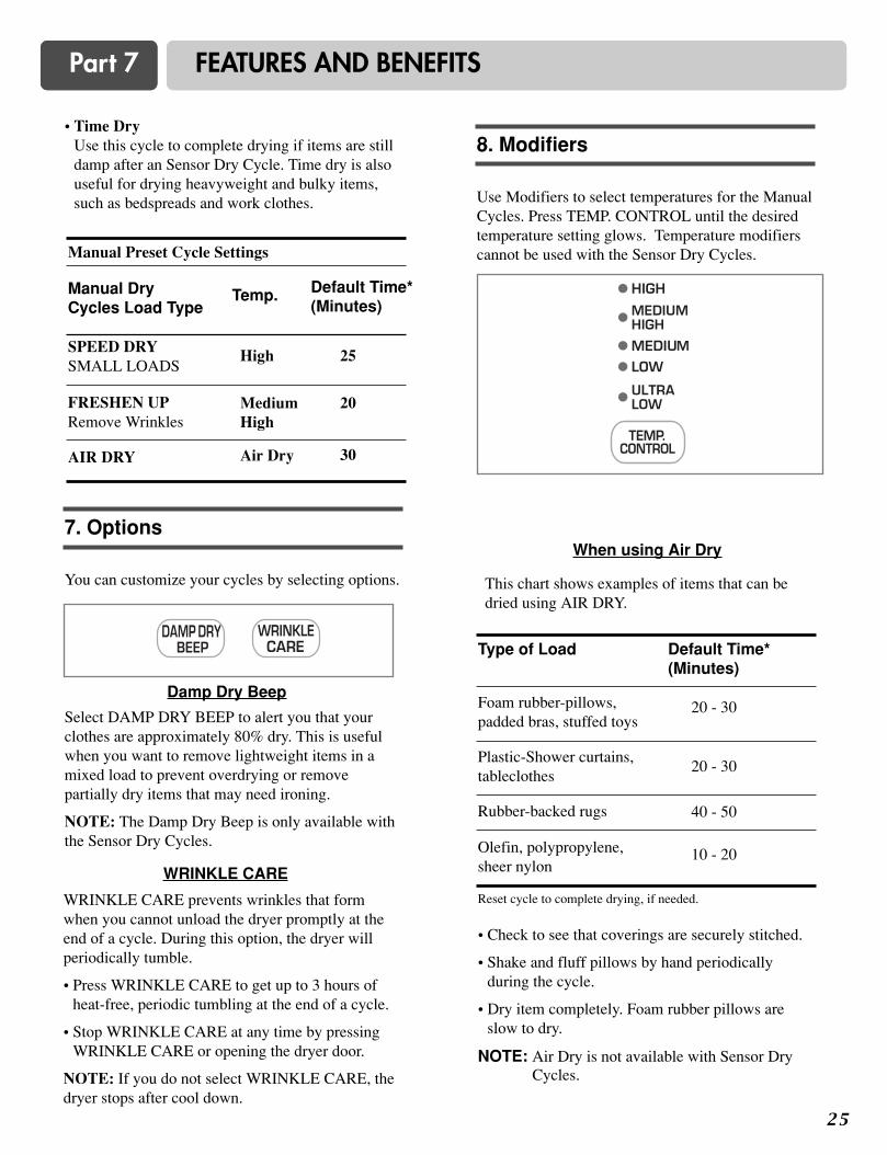
• Time DryUse this cycle to complete drying if items are stilldamp after an Sensor Dry Cycle. Time dry is alsouseful for drying heavyweight and bulky items,such as bedspreads and work clothes.
Select DAMP DRY BEEP to alert you that yourclothes are approximately 80% dry. This is usefulwhen you want to remove lightweight items in amixed load to prevent overdrying or removepartially dry items that may need ironing.
NOTE: The Damp Dry Beep is only available withthe Sensor Dry Cycles.
Damp Dry Beep
WRINKLE CARE prevents wrinkles that formwhen you cannot unload the dryer promptly at theend of a cycle. During this option, the dryer willperiodically tumble.
• Press WRINKLE CARE to get up to 3 hours ofheat-free, periodic tumbling at the end of a cycle.
• Stop WRINKLE CARE at any time by pressingWRINKLE CARE or opening the dryer door.
NOTE: If you do not select WRINKLE CARE, thedryer stops after cool down.
WRINKLE CARE
This chart shows examples of items that can bedried using AIR DRY.
Reset cycle to complete drying, if needed.
• Check to see that coverings are securely stitched.
• Shake and fluff pillows by hand periodicallyduring the cycle.
• Dry item completely. Foam rubber pillows areslow to dry.
NOTE: Air Dry is not available with Sensor DryCycles.
When using Air Dry
Manual DryCycles Load Type
Temp.
High
MediumHigh
Air Dry
Default Time*(Minutes)
25
20
30
SPEED DRYSMALL LOADS
FRESHEN UPRemove Wrinkles
AIR DRY
Manual Preset Cycle Settings
Type of Load Default Time*(Minutes)
Foam rubber-pillows,padded bras, stuffed toys
20 - 30
20 - 30
40 - 50
10 - 20
Plastic-Shower curtains,tableclothes
Rubber-backed rugs
Olefin, polypropylene,sheer nylon
You can customize your cycles by selecting options.
7. Options
Use Modifiers to select temperatures for the ManualCycles. Press TEMP. CONTROL until the desiredtemperature setting glows. Temperature modifierscannot be used with the Sensor Dry Cycles.
8. Modifiers
2 6
Part 7 FEATURES AND BENEFITS
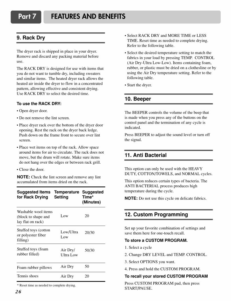
The dryer rack is shipped in place in your dryer.Remove and discard any packing material beforeuse.
The RACK DRY is designed for use with items thatyou do not want to tumble dry, including sweatersand similar items. The heated dryer rack allows theheated air inside the dryer to flow in a concentratedpattern, allowing effective and consistent drying.Use RACK DRY to select the desired time.
To use the RACK DRY:
• Open dryer door.
• Do not remove the lint screen.
• Place dryer rack over the bottom of the dryer dooropening. Rest the rack on the dryer back ledge.Push down on the frame front to secure over lintscreen.
• Place wet items on top of the rack. Allow spacearound items for air to circulate. The rack does notmove, but the drum will rotate. Make sure itemsdo not hang over the edges or between rack grill.
• Close the door.
9. Rack Dry
The BEEPER controls the volume of the beep thatis made when you press any of the buttons on thecontrol panel and the termination of any cycle isindicated.
Press BEEPER to adjust the sound level or turn offthe signal.
10. Beeper
This option can only be used with the HEAVYDUTY, COTTON/TOWELS, and NORMAL cycles.
This option reduces certain types of bacteria. TheANTI BACTERIAL process produces hightemperature during the cycle.
NOTE: Do not use this cycle on delicate fabrics.
11. Anti Bacterial
Set up your favorite combination of settings andsave them here for one-touch recall.
To store a CUSTOM PROGRAM.
1. Select a cycle
2. Change DRY LEVEL and TEMP. CONTROL.
3. Select OPTIONS you want.
4. Press and hold the CUSTOM PROGRAM.
To recall your stored CUSTOM PROGRAM
Press CUSTOM PROGRAM pad, then pressSTART/PAUSE.
NOTE: Check the lint screen and remove any lintaccumulated from items dried on the rack.
12. Custom Programming
Suggested Itemsfor Rack Drying
TemperatureSetting
SuggestedTime*(Minutes)
Washable wool items(block to shape andlay flat on rack)
Low 20
20/30
50/30
50
20
Low/UltraLow
Air Dry/Ultra Low
Air Dry
Air Dry
Stuffed toys (cottonor polyester fiberfilling)
Stuffed toys (foamrubber filled)
Foam rubber pillows
Tennis shoes
* Reset time as needed to complete drying.
• Select RACK DRY and MORE TIME or LESSTIME. Reset time as needed to complete drying.Refer to the following table.
• Select the desired temperature setting to match thefabrics in your load by pressing TEMP. CONTROL(Air Dry-Ultra Low-Low). Items containing foam,rubber, or plastic must be dried on a clothesline or byusing the Air Dry temperature setting. Refer to thefollowing table.
• Start the dryer.
2 7
Part 8 TROUBLESHOOTING GUIDE
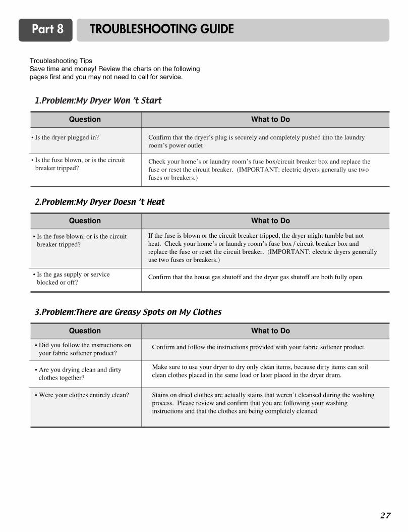
Troubleshooting TipsSave time and money! Review the charts on the followingpages first and you may not need to call for service.
1.Problem:My Dryer Won ’t Start
• Is the dryer plugged in?
• Is the fuse blown, or is the circuitbreaker tripped?
Confirm that the dryer’s plug is securely and completely pushed into the laundryroom’s power outlet
Check your home’s or laundry room’s fuse box/circuit breaker box and replace thefuse or reset the circuit breaker. (IMPORTANT: electric dryers generally use twofuses or breakers.)
Question What to Do
2.Problem:My Dryer Doesn ’t Heat
Question What to Do
• Is the fuse blown, or is the circuitbreaker tripped?
• Is the gas supply or serviceblocked or off?
If the fuse is blown or the circuit breaker tripped, the dryer might tumble but notheat. Check your home’s or laundry room’s fuse box / circuit breaker box andreplace the fuse or reset the circuit breaker. (IMPORTANT: electric dryers generallyuse two fuses or breakers.)
Confirm that the house gas shutoff and the dryer gas shutoff are both fully open.
3.Problem:There are Greasy Spots on My Clothes
Question What to Do
• Did you follow the instructions onyour fabric softener product?
• Are you drying clean and dirtyclothes together?
• Were your clothes entirely clean?
Confirm and follow the instructions provided with your fabric softener product.
Make sure to use your dryer to dry only clean items, because dirty items can soilclean clothes placed in the same load or later placed in the dryer drum.
Stains on dried clothes are actually stains that weren’t cleansed during the washingprocess. Please review and confirm that you are following your washinginstructions and that the clothes are being completely cleaned.

2 8
Part 8 TROUBLESHOOTING GUIDE
5.Problem:There is static in my clothes after drying
Question What to Do
4.Problem:There is Lint on my Clothes
Question What to Do
Please refer to the manual section on cleaning the lint filter, and please confirm that thelint filter is clean. It is important that the lint filter is clean before each new load oflaundry.
In order to reduce the amount of lint in a load of laundry, sort lint producers (like afuzzy white cotton towel) separately from clothes that might catch lint (such as a pairof black linen pants).
See comments below under There is static in my clothes after drying.
Divide your larger load into smaller loads.
Sometimes a person might forget to take a piece of paper or a tissue out of the pocketof a pair of pants, and this paper, tissue, or similar material can cause excess lint in aload of laundry. Confirm that the pockets of pants, shirts, and other articles of clothingare empty before washing and drying.
• Is your lint filter full?
• Did you properly sort your load oflaundry?
• Do your clothes have excess staticelectricity?
• Did you overload your dryer?
• Did you place any paper, tissue, orother similar material in the load?
• Did you use fabric softener?
• Did you over dry the load oflaundry?
• Are you drying synthetic, permanentpress, and blends?
Try using a fabric softener to reduce static electricity.
Over-drying a load of laundry can cause a build up of static electricity. Tryusing a fabric softener or adjust your settings and use a shorter drying time.
These materials can cause static to build up in a load of dried clothes. Tryusing a fabric softener.
6.Problem:The drying time is not consistent
Question
• Are you using consistent heatsettings and consistent load sizes?
The drying time for a load will vary depending on the heat setting, the type of heatused (electric, natural, or LP gas), the size of the load, the type of fabrics, the wetnessof the clothes, and the condition of the exhaust ducts and lint filer.
What to Do
2 9
Part 8 TROUBLESHOOTING GUIDE
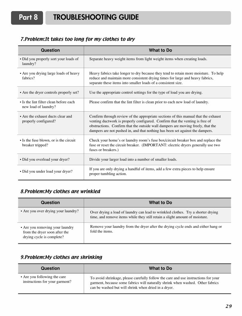
7.Problem:It takes too long for my clothes to dry
Question What to Do
• Did you properly sort your loads oflaundry?
• Are you drying large loads of heavyfabrics?
• Are the dryer controls properly set?
• Is the lint filter clean before eachnew load of laundry?
• Are the exhaust ducts clear andproperly configured?
• Is the fuse blown, or is the circuitbreaker tripped?
• Did you overload your dryer?
• Did you under load your dryer?
Separate heavy weight items from light weight items when creating loads.
Heavy fabrics take longer to dry because they tend to retain more moisture. To helpreduce and maintain more consistent drying times for large and heavy fabrics,separate these items into smaller loads of a consistent size.
Use the appropriate control settings for the type of load you are drying.
Please confirm that the lint filter is clean prior to each new load of laundry.
Confirm through review of the appropriate sections of this manual that the exhaustventing ductwork is properly configured. Confirm that the venting is free ofobstructions. Confirm that the outside wall dampers are moving freely, that thedampers are not pushed in, and that nothing has been set against the dampers.
Check your home’s or laundry room’s fuse box/circuit breaker box and replace thefuse or reset the circuit breaker. (IMPORTANT: electric dryers generally use twofuses or breakers.)
Divide your larger load into a number of smaller loads.
If you are only drying a handful of items, add a few extra pieces to help ensureproper tumbling action.
8.Problem:My clothes are wrinkled
Question What to Do
• Are you over drying your laundry?
• Are you removing your laundryfrom the dryer soon after thedrying cycle is complete?
Over drying a load of laundry can lead to wrinkled clothes. Try a shorter dryingtime, and remove items while they still retain a slight amount of moisture.
Remove your laundry from the dryer after the drying cycle ends and either hang orfold the items.
9.Problem:My clothes are shrinking
Question What to Do
• Are you following the careinstructions for your garment?
To avoid shrinkage, please carefully follow the care and use instructions for yourgarment, because some fabrics will naturally shrink when washed. Other fabricscan be washed but will shrink when dried in a dryer.
3 0
LG DRYER LIMITED WARRANTY – USA
1-800-243-0000
1-800-243-0000

2
CONTENIDO
PARTE 1 GARANTÍA E INSTRUCCIONES DE SEGURIDAD IMPORTANTES. ..................................................3-5
PARTE 2 PASOS INICIALES PARA LA INSTALACIÓN DE SU SECADORA...................................................6-11
Colocación de la Secadora............................... .........................................................................................6
Procedimiento para la Invertir Puerta............................ .............................................................................7
Conexión del Sistema de Escape y Ventilación................................. ........................................................8
Conexión del Suministro de Gas / Conexiones Eléctricas para Secadoras Eléctricas Solamente... .........9
Preparación de la Secadora / Confirmación de la Operación de la Fuente de Calor /
Flujo de Aire en la Secadora. ........................... ........................... ............ ........................... .................10
Instrucciones Adicionales para la instalación de su Secadora en una Casa Prefabricada o Móvil. ........11
PARTE 3. REQUERIMIENTOS ELÉCTRICOS PARA SECADORA ELÉCTRICA............... .............................12-16
Conexión de 3 Alambres con un Cordón de Alimentación............................................... .......................14
Conexión de 4 Alambres con un Cordón de Alimentación............................................ ..........................15
Conexión de 3 Alambres Opcional.................................................................................. ........................16
PARTE 4. REQUERIMIENTOS ELÉCTRICOS PARA SECADORAS A GAS....................... .................................17
PARTE 5. REQUERIMIENTOS E INSTRUCCIONES SOBRE EL GAS.................................. ...............................18
PARTE 6. REQUERIMIENTOS Y MANTENIMIENTO SOBRE EL ESCAPE........................ ............................19-20
PARTE 7. CARACTERÍSTICAS Y BENEFICIOS............................................................... ...............................21-26
Uso de su Secadora Para usar un Ciclo de Auto Secado.......................................................................22
Para usar un Ciclo de Secado Manual Para Detener su Secadora / Carga ....... ...................................23
Descripción de los Ciclos.............................................................................. ..........................................24
Operaciones / Modificadores...................................................................................................................25
Secado en Parrilla Alarma Anti-Bacterial / Programación Personalizada ...............................................26
PARTE 8. GUÍA PARA LA SOLUCIÓN DE PROBLEMAS.............................................. .................................27-29
GARANTÍA LIMITADA DE LA SECADORA LG.................................. ........................ .........................................30.

3
Part 1 GARANTÍA E INSTRUCCIONES DE SEGURIDAD IMPORTANTES
3
BÚSQUEDA DE ASISTENCIA SOBRE LA GARANTÍA
ADVERTENCIA! Para su seguridad, debe seguir las recomendaciones de
este manual. Para reducir el riesgo de incendio o explosión, o choque eléctrico, o paraprevenir daños a la propiedad, lesiones personales, o muerte cuando use su artefacto, sigalas precauciones básicas, incluyendo las siguientes.
Servicio de Garantía. La garantía de su secadora está impresa al final de este manual. Elservicio de garantía está disponible contactando su Centro de Servicio LG más cercano y por elperíodo de garantía desde la fecha de compra, si esta secadora es instalada y operada de acuerdo conlas instrucciones en este manual, LG reparará o remplazará cualquiera de sus partes mecánicas oeléctricas si están defectuosas en el material o en la fabricación.
Restricción de la Garantía : Si la secadora es utilizada para otro propósito que no sea el usofamiliar privado, toda cobertura de la garantía es efectiva por sólo 90 días.
Usted necesitará el número de modelo y de serie completos cuando solicite información. Lerecomendamos engrapar su recibo o cheque cobrado aquí, debido que necesitará sustentar la fecha desu compra original para obtener el servicio de la garantía. Los números de modelo y de serie de susecadora están ubicados en una placa que se encuentra en la parte frontal de su secadora detrás de lapuerta.
Utilice el siguiente espacio para anotar el número de modelo y de serie de su nueva secadora LG.
Modelo No.
No. de Serie
Fecha de Adquisición
❈ Engrape su recibo aquí.
!

Part 1
4
GARANTÍA E INSTRUCCIONES DE SEGURIDAD IMPORTANTES
1) Lea todas las instrucciones antes de usar el artefacto.
2) No seque artículos que hayan estado en contacto congasolina, solventes para lavado en seco, o cualquierotra sustancia inflamable o explosiva, ya quedespiden vapores que pueden incendiarse o explotar.
3) No permita que los niños jueguen sobre o dentro delartefacto Es necesario que supervise de cerca a losniños cuando utiliza el artefacto.
4) Antes de que el artefacto sea removido del servicio odesechado, quite la puerta del compartimiento desecado.
5) No meta la mano en el aparato si el tambor está enmovimiento.
6) No instale o almacene este artefacto donde estéexpuesto a la intemperie.
7) No fuerce los controles.
8) No repare o reemplace ninguna pieza del artefacto niintente darle servicio a menos que estéespecíficamente recomendado en las instrucciones demantenimiento para el usuario
9) No use calor para secar artículos que contengan huleespuma o materiales de textura similares al hule.
10) Limpie la malla para pelusas antes o después decada carga.
11) Mantenga el área alrededor de la abertura de escapey las áreas adyacentes libres de acumulación depelusa, polvo y sucio.
12) El interior del artefacto y el ducto de escape debenser limpiados periódicamente por personal deservicio calificado.
13) No coloque artículos que hayan sido expuestos aaceite de cocina dentro de la secadora. Artículoscontaminados con aceite de cocina puedencontribuir a una reacción química causante deincendiar una carga.
14) No use suavizantes de telas o productos paraeliminar la estática a menos que sea recomendadopor el fabricante de estos productos.
INSTRUCCIONES DE CONEXIÓN A TIERRA
Este artefacto debe estar conectado a tierra. En caso demal funcionamiento o avería, la conexión a tierrareduce el riesgo de choque eléctrico al proveer una rutade menor resistencia a la corriente eléctrica. Esteartefacto está equipado con un cordón que contiene unconductor equipo-tierra y un enchufe con conexión atierra. El enchufe debe ser conectado a un tomacorrienteadecuado, debidamente instalado y conectado a tierrade acuerdo con todos los códigos locales y ordenanzas.
ADVERTENCIA- Una incorrecta conexión delconductor equipo-tierra puede resultar en un riesgo dechoque eléctrico.
Verifique con un electricista calificado o un técnico deservicio si tiene alguna duda si el artefacto estádebidamente conectado a tierra.
No modifique el enchufe suministrado con el artefacto;si éste no encajase en el tomacorriente, haga que leinstalen un tomacorriente adecuado por un electricistacalificado.
ADVERTENCIA!Para ayudar a reducir el riesgo de choque eléctrico, incendio, o lesión personal odaño a la propiedad cuando use su secadora, por favor sea precavido y siga lasprecauciones de seguridad básicas, incluyendo las siguientes:
!
INSTRUCCIONES DE SEGURIDAD IMPORTANTES
GUARDE ESTAS INSTRUCCIONES

5
Part 1 GARANTÍA E INSTRUCCIONES DE SEGURIDAD IMPORTANTES
• No intente encender un fósforo, o cigarrillo, oencender ningún artefacto a gas o eléctrico.
• No toque ningún interruptor eléctrico. No useningún teléfono en su casa o edificio.
• Evacue la habitación, edificio o el área detodos los ocupantes.
• Llame inmediatamente a su proveedor de gasdesde el teléfono de un vecino. Sigacuidadosamente las instrucciones de suproveedor de gas.
• Si no puede contactar a su proveedor de gas,llame al departamento de bomberos.
Para reducir el riesgo de incendio o explosión,choque eléctrico, daño a la propiedad, lesionespersonales, o muerte cuando use este artefacto, porfavor siga todas las instrucciones e información,incluyendo las de este manual y las instrucciones einformación suministradas por su proveedor degas, incluyendo las siguientes:
• No almacene o use gasolina, solventes paralavado en seco, o cualquier otro vapor o líquidoinflamable en el área adyacente a este artefacto.
• No seque nada que alguna vez haya tenidocontacto con algo inflamable, aún después delavarlo.
• Ninguna lavadora puede remover completamenteel aceite. No seque ningún artículo que hayatenido contacto con cualquier clase de aceite,incluyendo aceite de cocinar.
• Artículos que contienen espuma, hule, materialessimilares al hule, plástico, o materiales similaresdeben secarse en el tendedero o utilizando elciclo de aire.
• La falta de cumplimiento de estas instruccionespuede resultar en incendio, muerte o lesionesserias.
• Un técnico o una compañía calificada debeefectuar la instalación y proveer el servicio a esteartefacto.
Decreto para la Seguridad delAgua Potable y los Tóxicos enCalifornia
Este decreto exige al gobernador de Californiapublicar una lista de substancias conocidas porel estado por causar cáncer, defectos congénitoso cualquier otro daño reproductivo y exige a losnegocios a advertir a sus consumidores sobre laposible exposición a dichas substancias.
Aparatos a gas pueden causar una exposiciónmenor a cuatro de estas substancias, a saberbenceno, monóxido de carbono, formaldehído yhollín, causadas principalmente por lacombustión incompleta de gas natural ocombustibles de petróleo licuado.
Secadoras debidamente ajustadas minimizarán lacombustión. La exposición a estas substanciaspuede ser minimizada más allá, ventilandoadecuadamente la secadora a la intemperie.
QUE HACER EN CASO DE OLERGAS:
ADVERTENCIA!• Mantenga los materiales y vapores
inflamables, como la gasolina, lejos de la
secadora.
• Coloque la secadora al menos 18 pulgadas
sobre el piso para instalación en el garaje.
• Si no cumple con estas instrucciones puede
resultar en muerte, explosión o incendio.
!
!
ADVERTENCIA!
6
Part 2 PASOS INICIALES PARA LA INSTALACIÓN DE SU SECADORA
50.5"
(128.27 cm)
42"3/4(108.6 cm)
27"(68.6 cm)
30"(76.2 cm)
3"(7.6 cm)
3"(7.6 cm)
48"2
(310 cm2)
24"2
(155 cm2)
31.5"1"(2.54 cm) (80.01 cm)
1"(2.54 cm)
14" max(35.6 cm)
18" (45.72 cm)
27"(68.6 cm)
0"(0 cm)
0"(0 cm)
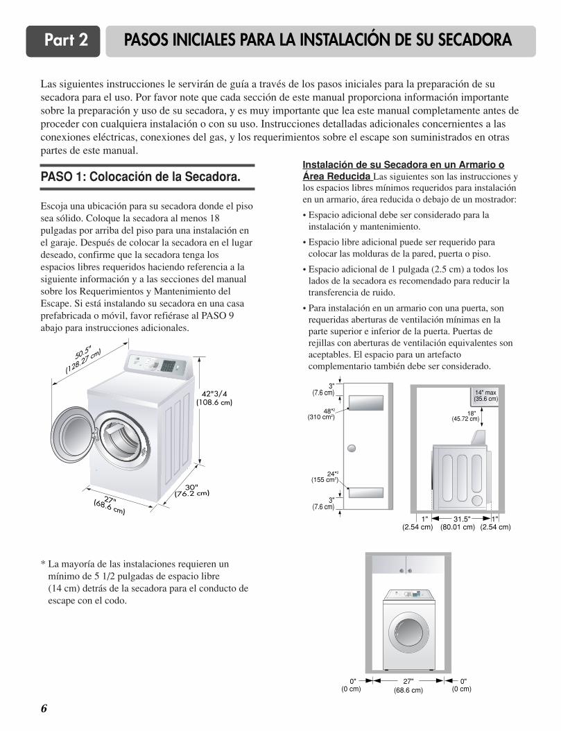
Las siguientes instrucciones le servirán de guía a través de los pasos iniciales para la preparación de susecadora para el uso. Por favor note que cada sección de este manual proporciona información importantesobre la preparación y uso de su secadora, y es muy importante que lea este manual completamente antes deproceder con cualquiera instalación o con su uso. Instrucciones detalladas adicionales concernientes a lasconexiones eléctricas, conexiones del gas, y los requerimientos sobre el escape son suministrados en otraspartes de este manual.
Escoja una ubicación para su secadora donde el pisosea sólido. Coloque la secadora al menos 18pulgadas por arriba del piso para una instalación enel garaje. Después de colocar la secadora en el lugardeseado, confirme que la secadora tenga losespacios libres requeridos haciendo referencia a lasiguiente información y a las secciones del manualsobre los Requerimientos y Mantenimiento delEscape. Si está instalando su secadora en una casaprefabricada o móvil, favor refiérase al PASO 9abajo para instrucciones adicionales.
Instalación de su Secadora en un Armario oÁrea Reducida Las siguientes son las instrucciones ylos espacios libres mínimos requeridos para instalaciónen un armario, área reducida o debajo de un mostrador:
• Espacio adicional debe ser considerado para lainstalación y mantenimiento.
• Espacio libre adicional puede ser requerido paracolocar las molduras de la pared, puerta o piso.
• Espacio adicional de 1 pulgada (2.5 cm) a todos loslados de la secadora es recomendado para reducir latransferencia de ruido.
• Para instalación en un armario con una puerta, sonrequeridas aberturas de ventilación mínimas en laparte superior e inferior de la puerta. Puertas derejillas con aberturas de ventilación equivalentes sonaceptables. El espacio para un artefactocomplementario también debe ser considerado.
* La mayoría de las instalaciones requieren unmínimo de 5 1/2 pulgadas de espacio libre (14 cm) detrás de la secadora para el conducto deescape con el codo.
PASO 1: Colocación de la Secadora.
7
Part 2 PASOS INICIALES PARA LA INSTALACIÓN DE SU SECADORA
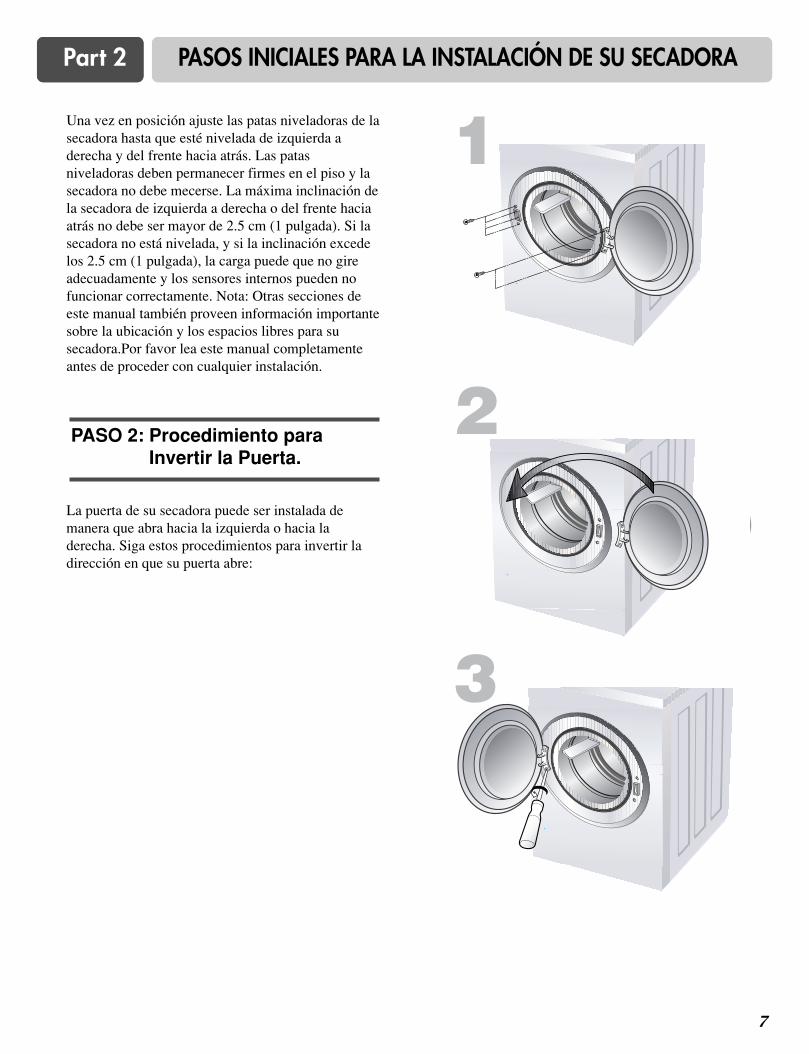
Una vez en posición ajuste las patas niveladoras de lasecadora hasta que esté nivelada de izquierda aderecha y del frente hacia atrás. Las patasniveladoras deben permanecer firmes en el piso y lasecadora no debe mecerse. La máxima inclinación dela secadora de izquierda a derecha o del frente haciaatrás no debe ser mayor de 2.5 cm (1 pulgada). Si lasecadora no está nivelada, y si la inclinación excedelos 2.5 cm (1 pulgada), la carga puede que no gireadecuadamente y los sensores internos pueden nofuncionar correctamente. Nota: Otras secciones deeste manual también proveen información importantesobre la ubicación y los espacios libres para susecadora.Por favor lea este manual completamenteantes de proceder con cualquier instalación.
La puerta de su secadora puede ser instalada demanera que abra hacia la izquierda o hacia laderecha. Siga estos procedimientos para invertir ladirección en que su puerta abre:
PASO 2: Procedimiento paraInvertir la Puerta.
1
2
3
8
Part 2 PASOS INICIALES PARA LA INSTALACIÓN DE SU SECADORA
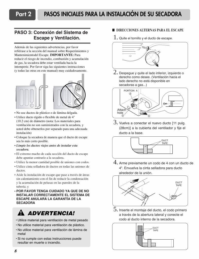
Además de las siguientes advertencias, por favorrefiérase a la sección del manual sobre Requerimientos yMantenimientodel Escape. IMPORTANTE: Parareducir el riesgo de incendio, combustión y acumulaciónde gas, la secadora debe estar ventilada hacia laintemperie. Por favor siga las siguientes instrucciones (y todas las otras en este manual) muy cuidadosamente.
• No use ductos de plástico o de lámina delgada.• Utilice ducto rígido o flexible de metal de 4"
(10.2 cm) de diámetro (nota: Los materiales paraventilación no son suministrados con la secadora, yusted debe obtenerlos por separado para una adecuadainstalación)
• Coloque la secadora de manera que el ducto de escapesea lo más corto posible.
• Limpie los ductos viejos antes de instalar estasecadora.
• El extremo macho de cada sección del ducto de escapedebe apuntar contrario a la secadora.
• Utilice la menor cantidad posible de uniones con codos.• Utilice cinta selladora de ductos en todas las uniones de
ductos.• Aísle la instalación de escape que pase a través de áreas
sin calentamiento con el fin de reducir la condensacióny la acumulación de pelusas en las paredes de latubería; y
• POR FAVOR TENGA CUIDADO YA QUE DE NOINSTALAR CORRECTAMENTE EL SISTEMA DEESCAPE ANULARÁ LA GARANTÍA DE LASECADORA
PASO 3: Conexión del Sistema deEscape y Ventilación.
ADVERTENCIA!• Utilice material para ventilación de metal pesado
• No utilice material para ventilación de plástico.
• No utilice material para ventilación de lámina demetal
• Si no cumple con estas instrucciones puederesultar en muerte o incendio.
!
� DIRECCIONES ALTERNAS PARA EL ESCAPE
1. Quite el tornillo y el ducto de escape.
2. Despegue y quite el lado inferior, izquierdo oderecho como desee. (Ventilación hacia ellado derecho no está disponible ensecadoras a gas...)
3. Vuelva a conectar el nuevo ducto [11 pulg.(28cm)] a la cubierta del ventilador y fije elducto a la base.
4. Arme previamente un codo de 4 con un ducto de4". Envuelva la cinta selladora para ductoalrededor de la unión.
5. Inserte el montaje del ducto, el codo primeroa través de la abertura lateral y conecte elcodo al ducto interno de la secadora.
Attachhole

9
Part 2 PASOS INICIALES PARA LA INSTALACIÓN DE SU SECADORA
(Secadora a Gas solamente). Además de lo siguiente, porfavor refiérase a la sección del manual sobreRequerimientos e Instrucciones del Gas.
1. Confirme que el tipo de gas disponible en su cuartode lavado sea el adecuado para su secadora. Lasecadora está preparada para Gas Natural con unaconexión de gas NPT de 3/8".
2. Remueva la tapa protectora de la conexión de gasdetrás de la secadora. Asegúrese de no dañar larosca de la tubería de la conexión de gas cuandoremueva la tapa protectora.
3. Conecte la secadora al suministro de gas en sucuarto de lavado utilizando un conector nuevoflexible de acero inoxidable (como se mencionóantes, sólo use un conector nuevo flexible de aceroinoxidable si es permitido por códigos locales)
4. Asegúrese de apretar todas las conexiones entre lasecadora y el suministro de gas en su cuarto delavado. Abra el suministro de gas en su cuarto delavado y verifique todas las conexiones de la tubería(internas y externas) para detectar fugas de gasutilizando un detector líquido de fugas no corrosivo.
5. Para una conexión a gas LP (Petróleo Licuado),refiérase a la sección de este manual sobreRequerimientos e Instrucciones del Gas.
1. Conector flexible nuevo de acero inoxidable. Utilice este tipo deconector sólo si es permitido por los códigos locales. Use unconector de diseño AGA Certificado.
2. Conector de tubo NPT de 1/8" (para verificar la presión deentrada de gas)
3. Válvula de Cierre de Equipo instalada a una distancia de 6’ (1.8 m) de la secadora.
4. Tubería de hierro. Más corta de 20’ (6.1 m) Use tubería de 3/8" .Más larga de 20’ (6.1 m) - Use tubería de 1/2".
5. Conexión de Gas N.P.T de 3/8" .
PASO 4: Conexión del Suministro de Gas
A continuación encontrará advertencias einstrucciones concernientes a la confección de laconexión eléctrica para secadoras eléctricas.Información detallada adicional concerniente a laconexión eléctrica es suministrada en la sección delmanual Requerimientos Eléctricos para la SecadoraEléctrica y es importante que usted lea esta seccióncompletamente, así como el resto del manual, antes detomar algún paso para instalar o usar esta secadora.
1. Use solamente un cordón de alimentación nuevolistado No. 10 por U.L.(alambre de cobreúnicamente) de tres conductores clasificado para240 Voltios (mínimo) 30 Amperios y que estáindicado de uso aceptable para una secadora deropa.
2. Un cordón de 4 alambres es requerido parainstalaciones y uso en casas prefabricadas (móvil) ydonde los códigos locales no permitan conexión atierra de este aparato a través del neutral.
3. El diagrama de cableado es provisto dentro de lacubierta de control de la secadora. Etiquete todoslos alambres antes de la desconexión cuando le estedando mantenimiento a la secadora, ya que erroresen el cableado pueden causar serias lesiones a ustedy dañar su secadora.
4. Para instrucciones adicionales de como conectar lasecadora a una fuente eléctrica, favor refiérase a lasección de este manual sobre RequerimientosEléctricos para Secadora Eléctrica.
PASO 5: Conexiones Eléctricas paraSecadoras Eléctricas Solamente
2
35
1
4
ADVERTENCIA!• Use un cordón de alimentación nuevo aprobado
por U.L. de 30 amp.o alambre de cobre sólidocalibre 10.
• Use un liberador de tensión aprobado por UL .• Desconecte la corriente antes de hacer las
conexiones eléctricas.• Conecte el alambre neutral (alambre blanco o
central) al terminal central.• El alambre a tierra alambre verde o descubierto)
debe conectarse al conector a tierra verde.• Asegúrese de apretar todas las conexiones
eléctricas.• Vea las instrucciones de instalación para unas
instrucciones completas.• De no seguir estas advertencias puede resultar
en incendio o choque eléctrico.
!
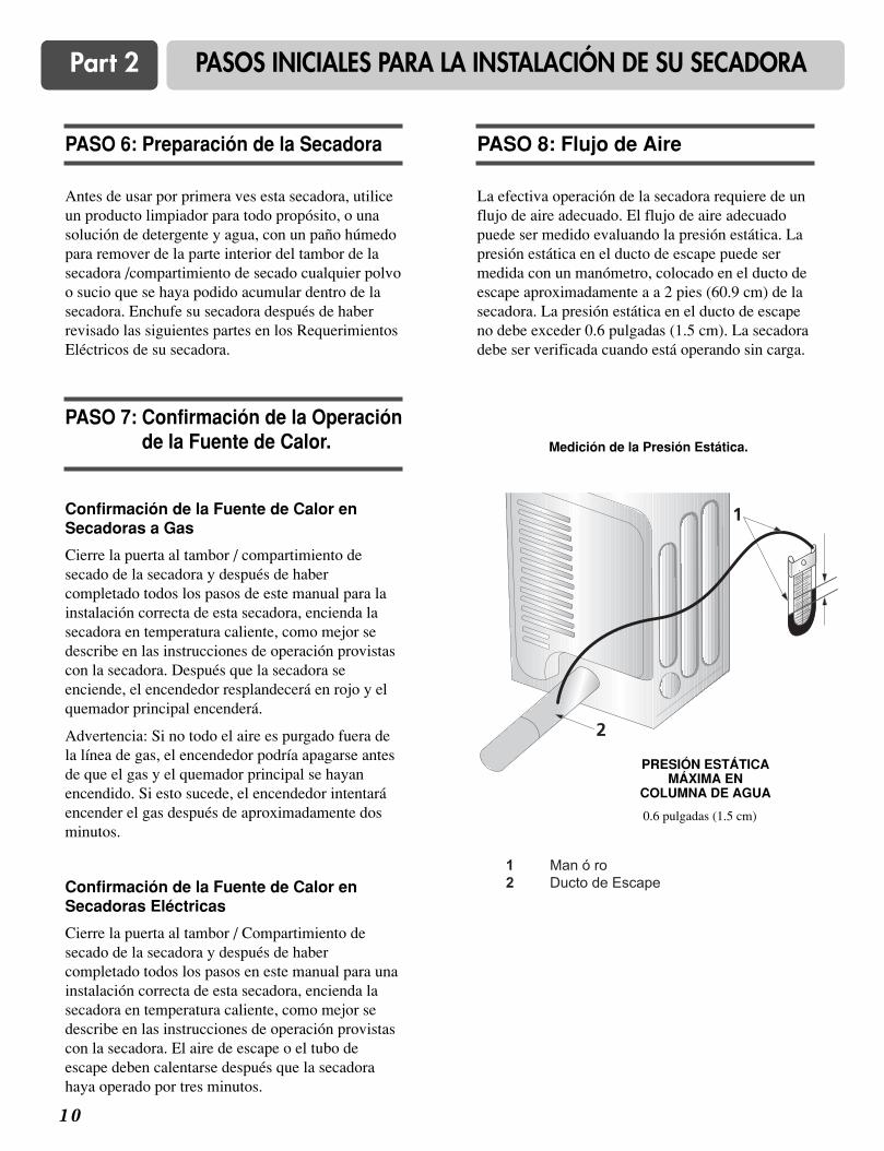
1 0
Part 2 PASOS INICIALES PARA LA INSTALACIÓN DE SU SECADORA
Antes de usar por primera ves esta secadora, utiliceun producto limpiador para todo propósito, o unasolución de detergente y agua, con un paño húmedopara remover de la parte interior del tambor de lasecadora /compartimiento de secado cualquier polvoo sucio que se haya podido acumular dentro de lasecadora. Enchufe su secadora después de haberrevisado las siguientes partes en los RequerimientosEléctricos de su secadora.
PASO 6: Preparación de la Secadora
La efectiva operación de la secadora requiere de unflujo de aire adecuado. El flujo de aire adecuadopuede ser medido evaluando la presión estática. Lapresión estática en el ducto de escape puede sermedida con un manómetro, colocado en el ducto deescape aproximadamente a a 2 pies (60.9 cm) de lasecadora. La presión estática en el ducto de escapeno debe exceder 0.6 pulgadas (1.5 cm). La secadoradebe ser verificada cuando está operando sin carga.
PASO 8: Flujo de Aire
Confirmación de la Fuente de Calor enSecadoras a Gas
Cierre la puerta al tambor / compartimiento desecado de la secadora y después de habercompletado todos los pasos de este manual para lainstalación correcta de esta secadora, encienda lasecadora en temperatura caliente, como mejor sedescribe en las instrucciones de operación provistascon la secadora. Después que la secadora seenciende, el encendedor resplandecerá en rojo y elquemador principal encenderá.
Advertencia: Si no todo el aire es purgado fuera dela línea de gas, el encendedor podría apagarse antesde que el gas y el quemador principal se hayanencendido. Si esto sucede, el encendedor intentaráencender el gas después de aproximadamente dosminutos.
Confirmación de la Fuente de Calor enSecadoras Eléctricas
Cierre la puerta al tambor / Compartimiento desecado de la secadora y después de habercompletado todos los pasos en este manual para unainstalación correcta de esta secadora, encienda lasecadora en temperatura caliente, como mejor sedescribe en las instrucciones de operación provistascon la secadora. El aire de escape o el tubo deescape deben calentarse después que la secadorahaya operado por tres minutos.
PASO 7: Confirmación de la Operaciónde la Fuente de Calor.
1
2
Medición de la Presión Estática.
0.6 pulgadas (1.5 cm)
PRESIÓN ESTÁTICAMÁXIMA EN
COLUMNA DE AGUA
1 Man ó ro2 Ducto de Escape

1 1
Part 2 PASOS INICIALES PARA LA INSTALACIÓN DE SU SECADORA
Las siguientes instrucciones se aplican ainstalaciones de la secadora en casas prefabricadas omóvil. La instalación en una casa prefabricada omóvil debe cumplir con los estándares de Seguridady Construcción de Casas Prefabricadas, Título 24CFR, Parte 32-80 o el Estándar CAN/CSA0Z240MH y los códigos y ordenanzas locales. Si no estáseguro de que la instalación cumplirá con estosestándares, por favor contacte a un profesional demantenimiento e instalación para que le ayude.
Las siguientes instrucciones se aplican a cualquierinstalación de la secadora en una casa prefabricadao móvil
1) Las secadoras a gas deben estar fijas al pisopermanentemente.
2) La conexión eléctrica para una secadora eléctricadebe ser de conexión de 4 alambres. Informaciónadicional detallada concerniente a la conexióneléctrica es suministrada en la sección del manualRequerimientos Eléctricos para la SecadoraEléctrica.
3) Para reducir el riesgo de combustión e incendio,la secadora debe estar ventilada hacia laintemperie.
4) Las secadoras eléctricas pueden ser ventiladashacia el exterior usando el panel trasero,izquierdo, derecho o inferior
5) Las secadoras a gas pueden ser ventiladas haciael exterior usando el panel trasero, izquierdo oinferior. Las secadoras a gas no pueden serventiladas al exterior usando el panel del ladoderecho debido a la cubierta del quemador.
6) El ducto de escape de la secadora debe estar fijoa la estructura de la casa prefabricada o móvil, yel ducto de escape debe estar hecho de unmaterial que resista fuego y combustión, y esrecomendable que utilice una tubería de metalflexible o rígido.
7) NO conecte el ducto de escape con ningún otroducto, ducto de ventilación, chimenea u otroducto de escape.
8) Asegúrese que la secadora tenga un buen accesoal aire fresco del exterior para una operaciónadecuada. La abertura para el aire fresco delexterior debe ser de por lo menos 25 pulgadas(163 cm).
9) Es importante que el espacio libre del ducto decualquier construcción combustible sea de por lomenos 2 pulgadas (5 cm), y cuando ventila lasecadora hacia la intemperie, la secadora puedeser instalada con un espacio libre de 1 pulgada alos lados y en la parte posterior de la secadora.
10) Favor notar que los materiales para laventilación no son provistos con la secadora.Usted debe obtener los materiales para laventilación necesarios para una adecuadainstalación.
PASO 9: Instrucciones Adicionalespara la Instalación de suSecadora en una CasaPrefabricada o Móvil.
ADVERTENCIA!NO conecte los ductos de escape con tornillosde metal o sujetadores que se extiendandentro del ducto.
! ADVERTENCIA!NO ventile el ducto de escape hacia abajo
de la casa prefabricada o móvil.
!
1 2
Part 3 REQUERIMIENTOS ELÉCTRICOS PARA SECADORAS ELÉCTRICAS
Las siguientes son instrucciones adicionales sobre las conexiones y requerimientos eléctricos para las secadoraseléctricas.
Advertencia Importante: Para ayudar a prevenir incendios, choque eléctrico, lesiones serias o muerte, el cableado y la conexión a tierra deben estar de acuerdo con la edición más reciente del código EléctricoNacional, ANSI/NFPA 70 y todas las regulaciones locales aplicables. Por favor contacte a un electricista calificadopara verificar el cableado y fusibles de su casa y para asegurar que tiene la energía eléctrica adecuada para elfuncionamiento de la secadora.
120V/208V, 60 Hertz, Instalación de 3-Alambres
120V/ 240V, 60 Hertz, Instalación de 3-Alambres
!
Instrucciones para la Conexión a Tierra desu Secadora Eléctrica:
a) Por favor note que el diagrama de cableado estálocalizado dentro de la cubierta del control de lasecadora.
b) Esta secadora debe ser conectada a un metalcon conexión a tierra, sistema de cableadopermanente, o un conductor equipo-tierra debecorrer con los conductores de circuito y estarconectado al terminal equipo-tierra o líneaprincipal de la secadora.
c) La secadora tiene su propia caja terminal la cualdebe estar conectada a una línea separada,60 Hertz, circuito de fase sencilla, circuito AC(corriente alterna), con fusible de 30 Amperios(el circuito debe tener fusibles en ambos ladosde la línea). EL SERVICIO ELÉCTRICOPARA LA SECADORA DEBE SER DELMÁXIMO RANGO DE VOLTAJE DESCRITOEN LA PLACA. NO CONECTE LASECADORA A UN CIRCUITO DE 110, 115,Ó 120 VOLTIOS. Hay elementos calefactoresdisponibles para secadoras que se conectarán aservicios eléctricos de diferente voltaje que losque se listan en la placa, tal como de 208voltios.
d) Si la distancia entre la caja de circuito y lasecadora es de 15 pies (4.50 m) o menos, use uncable No. 10 A.W.G. (de cobre únicamente)listado por U.L. (Underwriters Laboratories), ocomo lo requieran los códigos locales. Si es demás de 15 pies (4.50 m), use un cable No. 8A.W.G. (de cobre únicamente) listado por U.L(Underwriters Laboratories) o como lorequieran los códigos locales. Deje suficienteholgura en el cableado de manera que lasecadora pueda ser movida de su posicióncuando sea necesario.
e) La conexión del cordón de alimentación (cableflexible) entre el tomacorriente y la caja terminalde la secadora NO ES suministrada con lasecadora. El tipo del cable flexible y el calibre delalambre deben estar conforme con los códigoslocales y con las instrucciones de las páginassiguientes.
f) El método de cableado de la secadora es opcionaly sujeto a los requerimientos del código local.Refiérase a los ejemplos en la próxima página.
g) Usted debe seleccionar el método para cablear susecadora de acuerdo a los requerimientos de loscódigos locales y ordenanzas. Métodos deejemplo están incluidos en las siguientes páginas.
ADVERTENCIA!Etiquete todos los cables antes dedesconectarlos para darle mantenimiento a lasecadora, ya que errores en el cableadopueden causar lesiones serias a usted y dañarsu secadora.
!
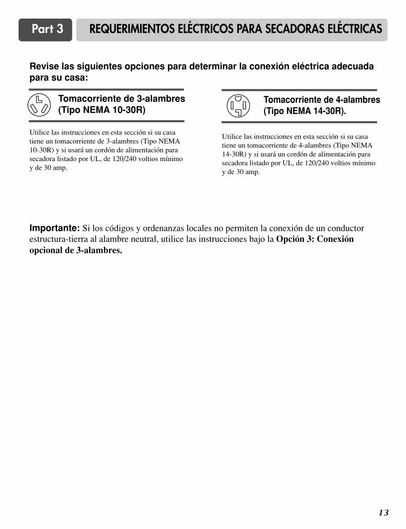
1 3
Part 3 REQUERIMIENTOS ELÉCTRICOS PARA SECADORAS ELÉCTRICAS
Utilice las instrucciones en esta sección si su casatiene un tomacorriente de 3-alambres (Tipo NEMA10-30R) y si usará un cordón de alimentación parasecadora listado por UL, de 120/240 voltios mínimoy de 30 amp.
Revise las siguientes opciones para determinar la conexión eléctrica adecuadapara su casa:
Importante: Si los códigos y ordenanzas locales no permiten la conexión de un conductorestructura-tierra al alambre neutral, utilice las instrucciones bajo la Opción 3: Conexiónopcional de 3-alambres.
Tomacorriente de 3-alambres(Tipo NEMA 10-30R)
Utilice las instrucciones en esta sección si su casatiene un tomacorriente de 4-alambres (Tipo NEMA14-30R) y si usará un cordón de alimentación parasecadora listado por UL, de 120/240 voltios mínimoy de 30 amp.
Tomacorriente de 4-alambres(Tipo NEMA 14-30R).

1 4
Part 3 REQUERIMIENTOS ELÉCTRICOS PARA SECADORAS ELÉCTRICAS
a. Tomacorriente de 3-alambres (Tipo NEMA 10-30R)b. Enchufe de 3-alambresc. Clavija neutrald. Terminales de espada con puntas levantadase. Liberador de tensión de 3/4 pulgadas. (1.9 cm)
aprobado por ULf. Terminales de anillog. Neutral (alambre blanco o central)
a. Conector a tierra externob. Alambre neutral a tierra (verde)c. Tornillo plateado del centro de la caja
terminald. Alambre neutral (alambre blanco o central)e. Liberador de tensión de 3/4 pulgadas
(1.9 cm) listado por UL
1. Afloje o remueva el tornillo central de la cajaterminal.
2. Conecte el alambre neutral (alambre blanco ocentral) del cordón de alimentación al tornillocentral plateado del terminal de la caja terminal.Apriete el tornillo
3. Conecte los otros alambres a los tornillosexternos de la caja terminal. Apriete los tornillos.
4. Apriete los tornillos del liberador de tensión.
5. Inserte la pestaña de la cubierta de la cajaterminal dentro de la ranura del panel trasero dela secadora. Asegure la cubierta con el tornillosujetador.
d
g f
a
Si los códigos y ordenanzas locales permiten laconexión de un conductor estructura-tierra alalambre neutral, utilice estas instrucciones. Si loscódigos y ordenanzas locales no permiten laconexión de un conductor estructura-tierra alalambre neutral, utilice las instrucciones bajo laSección 3: Conexión opcional de 3-alambres.
Opción 1: Conexión de 3-Alambres conun Cordón de Alimentación.

1 5
Part 3 REQUERIMIENTOS ELÉCTRICOS PARA SECADORAS ELÉCTRICAS
a. Tomacorriente de 4-alambres (Tipo NEMA14-30R)b. Enchufe de 4-clavijasc. Clavija a tierrad. Clavija neutrale. Terminal de espada con puntas levantadasf. Liberador de tensión de 3/4 pulgadas (1.9 cm)
aprobado por ULg. Terminales de anillo
a. Conector externo a tierra - Línea punteadamuestra la posición del alambre NEUTRAL atierra antes de ser movido al tornillo central dela caja terminal
b. Tornillo central plateado de la caja terminalc. Alambre verde para enganchar
1. Remueva el tornillo central de la caja terminal.
2. Remueva el alambre a tierra del artefacto (verde)del tornillo del conector externo a tierra. Sujételobajo el tornillo plateado central de la cajaterminal.
3. Conecte el alambre a tierra (verde o descubierto)del cable de alimentación al tornillo externo delconductor a tierra. Apriete el tornillo.
4. Conecte el alambre neutral (alambre blanco ocentral) del cordón de alimentación al tornillocentral plateado de la caja terminal.
a. Conector externo a tierrab. Alambre de cobre verde o descubierto del cordón
alimentaciónc. Liberador de tensión de 3/4 pulgadas (1.9 cm)
listado por ULd. Tornillo central plateado de la caja terminale. Alambre neutral a tierra (verde)f. Alambre neutral (blanco)
5. Conecte los otros alambres a los tornillosexternos de la caja terminal. Apriete los tornillos.
6. Apriete los tornillos del liberador de tensión.
7. Inserte la pestaña de la cubierta de la cajaterminal dentro de la ranura del panel trasero.Asegure la cubierta con el tornillo sujetador.
• Si los códigos y ordenanzas locales no permiten eluso de una conexión de 3 alambres, o estáinstalando la secadora en una casa móvil, debeusar una conexión de 4-alambres.
Opción 2: Conexión de 4-alambres conun Cordón de Alimentación.
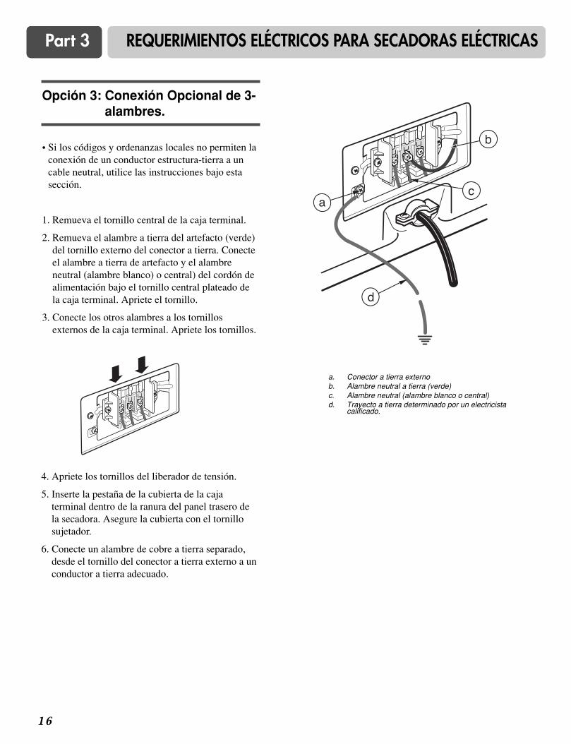
1 6
Part 3 REQUERIMIENTOS ELÉCTRICOS PARA SECADORAS ELÉCTRICAS
• Si los códigos y ordenanzas locales no permiten laconexión de un conductor estructura-tierra a uncable neutral, utilice las instrucciones bajo estasección.
1. Remueva el tornillo central de la caja terminal.
2. Remueva el alambre a tierra del artefacto (verde)del tornillo externo del conector a tierra. Conecteel alambre a tierra de artefacto y el alambreneutral (alambre blanco) o central) del cordón dealimentación bajo el tornillo central plateado dela caja terminal. Apriete el tornillo.
3. Conecte los otros alambres a los tornillosexternos de la caja terminal. Apriete los tornillos.
4. Apriete los tornillos del liberador de tensión.
5. Inserte la pestaña de la cubierta de la cajaterminal dentro de la ranura del panel trasero dela secadora. Asegure la cubierta con el tornillosujetador.
6. Conecte un alambre de cobre a tierra separado,desde el tornillo del conector a tierra externo a unconductor a tierra adecuado.
Opción 3: Conexión Opcional de 3-alambres.
a. Conector a tierra externob. Alambre neutral a tierra (verde)c. Alambre neutral (alambre blanco o central)d. Trayecto a tierra determinado por un electricista
calificado.
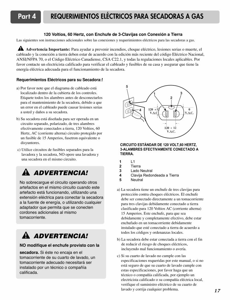
1 7
Part 4 REQUERIMIENTOS ELÉCTRICOS PARA SECADORAS A GAS
120 Voltios, 60 Hertz, con Enchufe de 3-Clavijas con Conexión a TierraLas siguientes son instrucciones adicionales sobre las conexiones y requerimientos eléctricos para las secadoras a gas.
Advertencia Importante: Para ayudar a prevenir incendios, choque eléctrico, lesiones serias o muerte, elcableado y la conexión a tierra deben estar de acuerdo con la edición más reciente del código Eléctrico Nacional,ANSI/NFPA 70, o el Código Eléctrico Canadiense, CSA C22.1, y todas la regulaciones locales aplicables. Porfavor contacte un electricista calificado para verificar el cableado y fusibles de su casa y asegurar que tiene laenergía eléctrica adecuada para el funcionamiento de la secadora.
Requerimientos Eléctricos para su Secadora:!
!
a) Por favor note que el diagrama de cableado estálocalizado dentro de la cubierta de los controles.Etiquete todos los alambres antes de desconectarlospara el mantenimiento de la secadora, debido a queun error en el cableado puede causar lesiones seriasa usted y daños a su secadora.
b) Su secadora está diseñada para ser operada en uncircuito separado, polarizado, de tres alambresefectivamente conectados a tierra, 120 Voltios, 60Hertz, AC (corriente alterna) circuito protegido porun fusible de 15 Amperios, fusetron equivalente odisyuntores.
c) Utilice circuitos de fusibles separados para lalavadora y la secadora, NO opere una lavadora yuna secadora en el mismo circuito.
a) La secadora tiene un enchufe de tres clavijas paraprotección contra choques eléctricos. El enchufedebe ser conectado directamente a un tomacorrientepara tres clavijas debidamente conectado a tierraclasificado para 120 Voltios AC (corriente alterna)15 Amperios. Este enchufe, para que seadebidamente y completamente efectivo, debe estarenchufado en un tomacorriente debidamenteinstalado que esté conectado a tierra de acuerdo atodos los códigos y ordenanzas locales.
b) La secadora debe estar conectada a tierra con el finde reducir el riesgo de choques eléctricos,incluyendo mal funcionamiento o avería.
c) Si su cuarto de lavado no cumple con lasespecificaciones requeridas por este manual, o si noestá seguro de que su cuarto de lavado cumple conestas especificaciones, por favor haga que untécnico o compañía calificada, por ejemplo unelectricista calificado o su compañía eléctrica local,verifique el suministro eléctrico de su cuarto delavado y corrija cualquier problema.
ADVERTENCIA!No sobrecargue el circuito operando otrosartefactos en el mismo circuito cuando esteartefacto está funcionando, utilizando unaextensión eléctrica para conectar la secadoraa la fuente de energía, o utilizando cualquieradaptador que permita que se conectencordones adicionales al mismotomacorriente.
!
CIRCUITO ESTÁNDAR DE 120 VOLT,60 HERTZ,3-ALAMBRES EFECTIVAMENTE CONECTADO ATIERRA.
1 L12 Tierra3 Lado Neutral4 Clavija Redondeada a Tierra5 Neutral
21 3
5
4
V.A.C.120 + 12
0 V.A.C.
120 ± 12 V.A.C
ADVERTENCIA!NO modifique el enchufe provisto con la
secadora. Si éste no encaja en eltomacorriente de su cuarto de lavado, untomacorriente adecuado necesitará serinstalado por un técnico o compañíacalificada.
!

1 8
Part 5 REQUERIMIENTOS E INSTRUCCIONES SOBRE EL GAS
Las siguientes son instrucciones e información importante concernientes a los requerimientos para el suministro yservicio del gas para las secadoras a gas. Advertencia Importante: El suministro y servicio del gas para lassecadoras a gas debe cumplir con los códigos y ordenanzas locales. Si no existen códigos y ordenanzas locales en suárea, el suministro y servicio del gas para su secadora a gas debe cumplir con la más reciente edición del CódigoNacional de Gas Combustible, ANSI Z223.1 / NFPA 54.
1. Requerimientos del suministro de gas: El serviciode Gas Petróleo Licuado (L.P.) (2,500 Btu/ft3 (93.1MJ/m3)) debe ser suministrado a una presión decolumna de agua de 10 + 1.5 pulgadas.
2. Importante: NO conecte la secadora al servicio deGas Petróleo Licuado (LP) sin convertir la válvulade gas.
3. Un técnico calificado debe realizar la conversión deGas LP. Contacte su oficina local de servicio de gassi requiere asistencia adicional o información.
4. Aísle la secadora del sistema de tuberías delsuministro de gas cerrando la válvula individual decierre manual, durante las pruebas de presión delsistema de suministro de gas a la presión de pruebaigual o menor que 2/1 psi (3.45 kPa).
5. Requerimientos de la Línea de Suministro. Sucuarto de lavado debe tener una línea rígida desuministro de gas hasta la secadora. En USA, unaválvula individual de cierre manual DEBE serinstalada a no más de 6 pies (1.8 m) de la secadorade acuerdo con Código Nacional de GasCombustible ANSI Z223.1. Un conector de tuberíaN.P.T. de 1/8 pulgada debe ser instalado como semuestra.
6. Si usa una tubería rígida, deberá ser de 1/2 pulgadaIPS. Si es aceptable por los códigos y ordenanzaslocales así como por su suplidor de gas, podráusarse tubería aprobada de 3/8 de pulgada paradistancias menores de 20 pies (6.1 m). Tuberías más grandes deberán usarse paradistancias mayores de 20 pies (6.1 m). También esimportante que utilice sellador de uniones que seainsoluble en gas LP.
7. Para reducir el peligro de fugas de gas, explosión, eincendio, por favor siga y cumpla con lo siguiente
Instrucciones y ADVERTENCIAS:
• Conecte la secadora al tipo de gas indicado en laplaca de la secadora;
• Utilice conectores nuevos flexibles de aceroinoxidable;
• Utilice cinta de Teflón y sellador de unionesinsoluble en gas LP en todas las roscas de lastuberías;
• Purgue el suministro de gas de aire y sedimentosantes de conectarlo a la secadora; con el propósito deevitar contaminación de la válvula de gas, antes deapretar la conexión entre el suministro de gas y lasecadora, purgue el aire que queda hasta que el olor agas sea detectado; y
• NO use una flama para detectar fugas de gas; en sulugar, utilice un líquido detector de fugas nocorrosivo.
ADVERTENCIA!• Utilice una línea nueva de suministro de gas
aprobada por AGA o CSA.
• Instale una válvula de cierre.
• Asegúrese de apretar todas las conexiones degas
• Si está conectado a LP, haga que un técnicocalificado se asegure que la presión de gas noexceda la columna de agua de 13 pulgadas.
• Ejemplos de los técnicos calificados incluyenpersonal con licencia sobre calefacciónpersonal autorizado de la compañía de gas, ypersonal autorizado de servicio.
• De no cumplir lo aquí indicado puedeocasionar
la muerte, explosión o incendio.
!
ADVERTENCIA!NO intente desmontar la secadora,esta acción requiere la atención yherramientas de un técnico o compañíaautorizada y calificada.
!
!

1 9
Part 6 REQUERIMIENTOS Y MANTENIMIENTO SOBRE EL ESCAPE
Las siguientes son instrucciones e información importante concernientes a los requerimientos del escape para susecadora.
Advertencia Importante: Para reducir el riesgo de incendio, combustión, o acumulación de gasescombustibles, NO dirija el escape de la secadora hacia un área cerrada y no ventilada, como un ático, pared, techo,sótano, chimenea, salidas de gas, o espacio oculto de un edificio. Para reducir el riesgo de incendio, NO utilice ductosde plástico o lámina delgada para el escape de la secadora.
Requerimientos e Instrucciones del Escape1. Los materiales para la ventilación no son
suministrados con la secadora y usted deberáobtener los materiales necesarios localmente. Porejemplo, el extremo exterior de la tubería deescape debe tener una campana con compuertascon bisagras para evitar corrientes de airescuando la secadora no está en uso.
2. El ducto de escape debe ser de 4 pulgadas (10.2 cm) de diámetro sin obstrucciones. El ductode escape debe mantenerse lo más corto posible.Asegúrese de limpiar cualquier ducto viejo antesde instalar su nueva secadora.
3. Se recomienda un ducto de metal rígido. Noinstale un ducto flexible en espacios ocultos. Unducto de metal flexible no-combustible esaceptado. No utilice ductos de plástico o láminadelgada.
4. NO use tornillos para láminas de metal en lasuniones de las tuberías de escape u otrossujetadores que puedan introducirse en el ducto yque puedan atrapar pelusas y reducir la eficienciadel sistema de escape. Asegure todas las unionescon cinta para ductos.
5. Para maximizar los resultados de la operación,por favor observe las limitaciones del largo delducto según la tabla de arriba.
!
Número deCodos de 90°
Tipos deCampana
Recomendado
Longitud máxima delducto de metal rígido de4" (10.2 cm) de diámetro
Longitud máxima delducto de metal flexible
de 4" (10.2 cm) dediámetro
NOTA : Deduzca 6 pies (1.8 m) por cada codo adicional.No se recomienda usar más de 4 codos de 90°.
Úsese únicamente parainstalaciones
de carrera corta
0
1
2
3
4
0
1
2
3
4
65 pies (19.8 m)
55 pies (16.8 m)
47 pies (14.3 m)
36 pies (11.0 m)
28 pies (8.5 m)
45 pies (13.7 m)
35 pies (10.7 m)
30 pies (9.1 m)
25 pies (7.6 m)
20 pies (6.1 m)
55 pies (16.8 m)
47 pies (14.3 m)
41 pies (12.5 m)
30 pies (9.1 m)
22 pies (6.7 m)
35 pies (10.7 m)
27 pies (8.2 m)
21 pies (6.4 m)
17 pies (5.2 m)
15 pies (4.5m)
4”
(10.2 cm)
4”
(10.2 cm)
2-1/2”
(6.35 cm)
2 0
Part 6 REQUERIMIENTOS Y MANTENIMIENTO SOBRE EL ESCAPE
Mantenimiento del Escape y la Secadora
1. Después de un año de uso, el interior y todo el sistemade escape de la secadora debe ser examinado ylimpiado si es necesario.
2. Debe inspeccionar y limpiar el ducto de escape por lomenos una vez al año.
3. Verifique la campana frecuentemente para asegurarseque las compuertas se están moviendo libremente, queno hayan sido empujadas hacia adentro, y que nadahaya sido recargado contra las compuertas.
4. Un técnico de servicio o compañía calificada debe serutilizada para realizar este mantenimiento.
5. Un equipo de Ventilación Flexible, disponible a costoextra, puede utilizarse cuando el escape de la secadoraesta situado en lugares difíciles de alcanzar. Esteequipo viene en dos piezas, una se adjunta a lasecadora y la otra a la salida del escape de la pared.Después de haber fijado las dos piezas por separado ala secadora y a la pared, la secadora puede retornar asu posición final, para luego conectar las dos piezasentre si.
7. Usualmente, el tambor de la secadora no necesitacuidado. Limpie el exterior de la secadora cuando seanecesario, y siempre inmediatamente cuando sederrame en la secadora cualquier detergente,blanqueador, u otro producto para lavar, debido queestos productos pueden causar daños permanentes alacabado exterior de la secadora.
8. Limpie el panel de control con un paño húmedocuando sea necesario. Advertencia: los productos depre-lavados en spray pueden dañar el acabado delpanel de control.
9. Por favor limpie el filtro de pelusa antes o después desecar cada carga.
10. Siempre asegúrese que el filtro de pelusa esté limpioantes de empezar una nueva carga, debido a que unfiltro de pelusa obstruido puede aumentar el tiempode secado.
11. Anualmente remueva el filtro de pelusa y colóquelobajo el ducto de la aspiradora. Vea el ítem #2 arriba.
12. Por favor note que el diagrama de cableado selocaliza dentro de la cubierta de los controles de lasecadora. Etiquete todos los cables antes dedesconectarlos al darle mantenimiento a la secadora,debido a que errores en el cableado pueden causarlesiones serias a usted y daño a su secadora.
Limpieza de la Malla de Pelusa1. Limpie el filtro de pelusa antes o después de haber
secado cada carga. Siempre asegúrese que el filtrode pelusa esté limpio antes de empezar una nuevacarga, debido a que un filtro de pelusa obstruidopuede aumentar el tiempo de secado.
2. Para limpiarlo, tire de la malla de pelusa haciaarriba y enrolle la pelusa fuera de la malla con losdedos. No enjuague o lave la malla para remover lapelusa, debido a que la pelusa mojada es difícil dequitar. Empuje la malla de pelusa firmemente devuelta a su lugar.
3. Siempre asegúrese que la malla de pelusa estéfirmemente colocada antes de operar la secadora.Operar la secadora sin la malla de pelusa puedecausar sobrecalentamiento y causar daño a lasecadora como a los artículos que está secando.
4. Algunos artículos pueden soltar más pelusa queotros (por ejemplo, toallas hechas de fibrassintéticas y fibras naturales), causando que la mallade pelusa se congestione más rápidamente.Remueva la pelusa de la malla de pelusa antes ydespués de haber secados estos artículos, tales comotoallas nuevas.
5. En el caso que la pelusa se caiga de la malla dentrode la secadora durante la remoción, verifique elconducto de escape y quite cualquier pelusa.
6. El detergente para lavar y los residuos delsuavizante de tela se pueden acumular en la mallade pelusa, causando tiempos de secado más largos.La malla probablemente se bloqueará si cae pelusasobre ella. Con el fin de prevenir este tipo deacumulación, y ayudar a asegurar unfuncionamiento adecuado de su secadora, limpie lamalla de pelusa con un cepillo de nailon cada seismeses, o si es necesario, más frecuentemente. Elfiltro de pelusa también puede lavarse de lasiguiente manera:
a) Después de haber enrollado la pelusa fuera de lamalla con los dedos, moje ambos lados de la mallacon agua caliente o tibia.
b) Moje un cepillo de nailon con agua caliente ydetergente líquido y restriegue la malla de pelusapara remover la acumulación de residuos dedetergente y suavizante de tela.
c) Repita el proceso como sea necesario.
d) Después que los residuos hayan sido removidos,enjuague la malla con agua caliente.
e) Después de secar la malla de pelusa con una toallalimpia, Coloqué firmemente la malla de vuelta en lasecadora.
ADVERTENCIA!Desconecte la energía eléctrica de la secadoraantes de efectuar limpieza o mantenimiento.
!
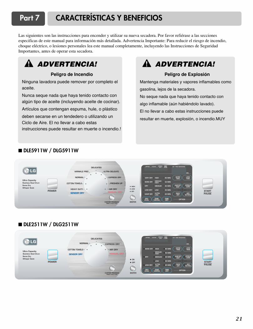
2 1
Part 7 CARACTERÍSTICAS Y BENEFICIOS
� DLE5911W / DLG5911W
� DLE2511W / DLG2511W
Las siguientes son las instrucciones para encender y utilizar su nueva secadora. Por favor refiérase a las seccionesespecificas de este manual para información más detallada. Advertencia Importante: Para reducir el riesgo de incendio,choque eléctrico, o lesiones personales lea este manual completamente, incluyendo las Instrucciones de SeguridadImportantes, antes de operar esta secadora.
ADVERTENCIA!Peligro de Incendio
Ninguna lavadora puede remover por completo elaceite.
Nunca seque nada que haya tenido contacto conalgún tipo de aceite (incluyendo aceite de cocinar).
Artículos que contengan espuma, hule, o plástico
deben secarse en un tendedero o utilizando unCiclo de Aire. El no llevar a cabo estasinstrucciones puede resultar en muerte o incendio.!
! ADVERTENCIA!Peligro de Explosión
Mantenga materiales y vapores inflamables como
gasolina, lejos de la secadora.
No seque nada que haya tenido contacto con
algo inflamable (aún habiéndolo lavado).
El no llevar a cabo estas instrucciones puede
resultar en muerte, explosión, o incendio.MUY
!
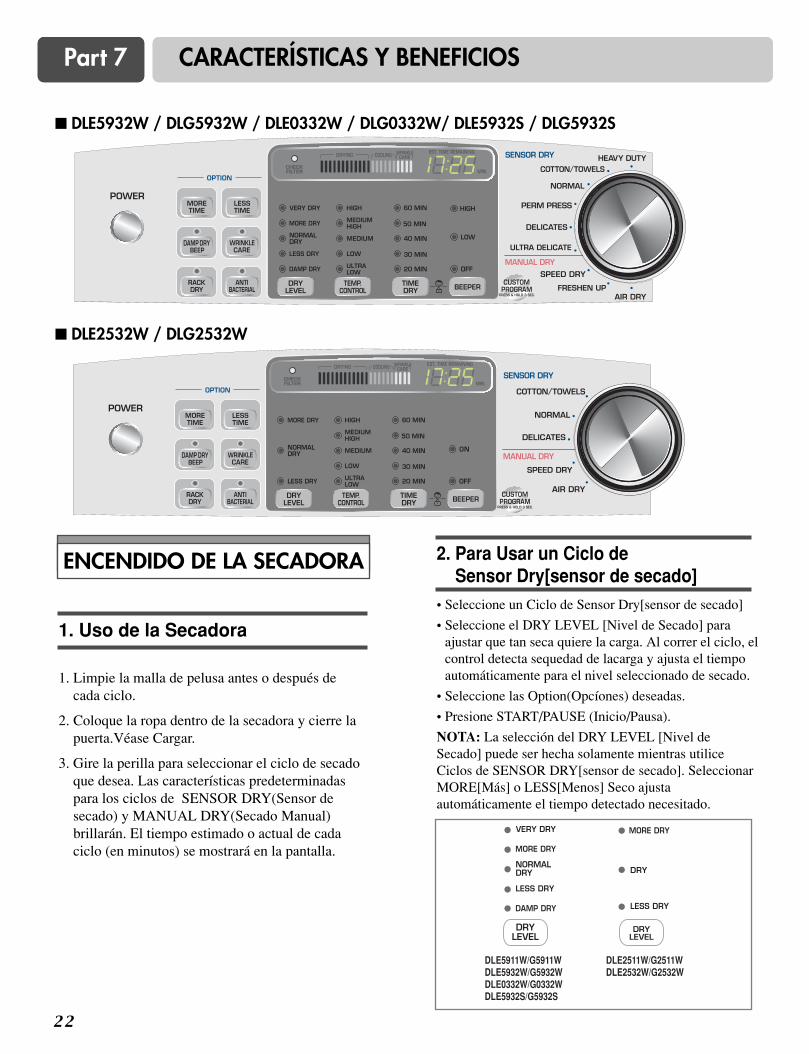
2 2
Part 7 CARACTERÍSTICAS Y BENEFICIOS
� DLE5932W / DLG5932W / DLE0332W / DLG0332W/ DLE5932S / DLG5932S
� DLE2532W / DLG2532W
ENCENDIDO DE LA SECADORA
1. Limpie la malla de pelusa antes o después decada ciclo.
2. Coloque la ropa dentro de la secadora y cierre lapuerta.Véase Cargar.
3. Gire la perilla para seleccionar el ciclo de secadoque desea. Las características predeterminadaspara los ciclos de SENSOR DRY(Sensor desecado) y MANUAL DRY(Secado Manual)brillarán. El tiempo estimado o actual de cadaciclo (en minutos) se mostrará en la pantalla.
1. Uso de la Secadora • Seleccione un Ciclo de Sensor Dry[sensor de secado]
• Seleccione el DRY LEVEL [Nivel de Secado] paraajustar que tan seca quiere la carga. Al correr el ciclo, elcontrol detecta sequedad de lacarga y ajusta el tiempoautomáticamente para el nivel seleccionado de secado.
• Seleccione las Option(Opcíones) deseadas.
• Presione START/PAUSE (Inicio/Pausa).
NOTA: La selección del DRY LEVEL [Nivel deSecado] puede ser hecha solamente mientras utiliceCiclos de SENSOR DRY[sensor de secado]. SeleccionarMORE[Más] o LESS[Menos] Seco ajustaautomáticamente el tiempo detectado necesitado.
2. Para Usar un Ciclo de Sensor Dry[sensor de secado]
DLE5911W/G5911WDLE5932W/G5932WDLE0332W/G0332WDLE5932S/G5932S
DLE2511W/G2511WDLE2532W/G2532W

2 3
Part 7 CARACTERÍSTICAS Y BENEFICIOS
• Seleccione un Ciclo de manual dry.• Presione MORE TIME[Más Tiempo] o LESS
TIME[Menos Tiempo] hasta que el tiempo deseado desecado se muestre en pantalla. Presione MORETIME[Más Tiempo] o LESS TIME[Menos Tiempo] y eltiempo en pantalla cambiará por intervalos de un minuto.
NOTA: Las características de MORE TIME[MásTiempo] o LESS TIME[Menos Tiempo] pueden serusadas con los ciclos de manual dry[Secado Manual], timedry[tiempo de secado y Rack Dry[Secado con Parrilla].
• Presione TEMP. CONTROL (Control Temp.) hasta quese brille el indicador temperatura deseada.
• (PASO OPCIONAL) Si lo desea, seleccioneOption(Opcíones) Para más detalles vea"Option(Opcíones)".
• Presione START/PAUSE[Inicio/Pausa]. Asegúrese deque la puerta esté cerrada.
• Si usted no presiona START/PAUSE[Inicio/Pausa] enun lapsode 10 minutos de haber seleccionado el ciclo, lasecadora se apaga automáticamente.
• Si desea terminar el ciclo de secado después de haberpresionado START/PAUSE[Inicio/Pausa], presioneSTART/PAUSE[Inicio/Pausa] nuevamente.
3. Para Usar un Ciclo de manualdry[Secado Manual]
Cargar correctamente su secadora le puede ahorrargastos y prolongar la vida de sus prendas.
Sugerencias de Carga
• Cargue la secadora por el espacio que ocupe lacarga, no por su peso.
• No sobrecargue la secadora. Esto causa secadoincompleto y arrugas en la ropa.
Heavy Work Clothes[Ropas de Uso Pesado]4 pantalones vaqueros4 pantalones de trabajo4 camisas de trabajo
2 pantalones de ejercicios2 sudaderas
Towels[Toallas]10 toallas de baño10 toallas de mano
14 paños para limpiar
Mixed Load[Carga Mixta]3 sabanas (1 grande, 2 medianas)4 fundas de almohadas3 camisas3 blusas
9 camisetas9 calzoncillos10 pañuelos
Los siguientes son ejemplos de cargas paraSecadoras de Súper Capacidad:
5. Cargar
Para detener su secadora en cualquier momentoPresione Start/Pause[Inicio/Pausa] o abra la puerta.
Pausar o ReiniciarPara pausar la secadora en cualquier momentoAbra la puerta ó presioneSTART/PAUSE[Inicio/Pausa] una vez.Para reiniciar la secadoraCierre la puerta. PresioneSTART/PAUSE[Inicio/Pausa].NOTA: El secado continuará desde donde se hayainterrumpido el ciclo si cierra la puerta y presionaSTART/PAUSE[Inicio/Pausa] en un lapso de 10minutos. Si el ciclo es interrumpido por mas de 10minutos, la secadora se apagará automáticamente.Seleccione un nuevo ciclo antes de reiniciar lasecadora.
CHILD LOCK [Seguro de Niños]
Esta característica permite bloquear las seleccionespara prevenir que los niños las puedan cambiar.Usted también puede usar el Seguro de Niños paraprevenir cambios no intencionados de los ciclos ode las opciones durante la operación de secado. Paradesactivar la característica de Seguro de Niños:Presione y sostenga los botones RACKDRY[Secado con Parrilla] y ANTI-BACTERIALpor dos segundos. Un sólo sonido de ALARMA(BEEP) se escuchará y se mostrará CL en lapantalla. Para quitar el seguro, presione y sostengalos botones RACK DRY[Secado con Parrilla] yANTI-BACTERIAL por dos segundos. La luzindicadora se apagará.
4. Para Detener la Secadora
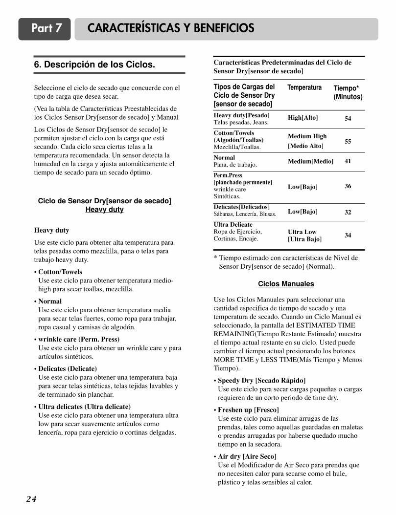
2 4
Part 7 CARACTERÍSTICAS Y BENEFICIOS
Seleccione el ciclo de secado que concuerde con eltipo de carga que desea secar.
(Vea la tabla de Características Preestablecidas delos Ciclos Sensor Dry[sensor de secado] y Manual
Los Ciclos de Sensor Dry[sensor de secado] lepermiten ajustar el ciclo con la carga que estásecando. Cada ciclo seca ciertas telas a latemperatura recomendada. Un sensor detecta lahumedad en la carga y ajusta automáticamente eltiempo de secado para un secado óptimo.
Heavy duty
Use este ciclo para obtener alta temperatura paratelas pesadas como mezclilla, pana o telas paratrabajo heavy duty.
• Cotton/TowelsUse este ciclo para obtener temperatura medio-high para secar toallas, mezclilla.
• NormalUse este ciclo para obtener temperatura mediapara secar telas fuertes, como ropa para trabajar,ropa casual y camisas de algodón.
• wrinkle care (Perm. Press)Use este ciclo para obtener un wrinkle care y paraartículos sintéticos.
• Delicates (Delicate)Use este ciclo para obtener una temperatura bajapara secar telas sintéticas, telas tejidas lavables yde terminado sin planchar.
• Ultra delicates (Ultra delicate)Use este ciclo para obtener una temperatura ultralow para secar suavemente artículos comolencería, ropa para ejercicio o cortinas delgadas.
* Tiempo estimado con características de Nivel deSensor Dry[sensor de secado] (Normal).
Tipos de Cargas delCiclo de Sensor Dry[sensor de secado]
Temperatura Tiempo*(Minutos)
Ciclo de Sensor Dry[sensor de secado] Heavy duty
Use los Ciclos Manuales para seleccionar unacantidad especifica de tiempo de secado y unatemperatura de secado. Cuando un Ciclo Manual esseleccionado, la pantalla del ESTIMATED TIMEREMAINING(Tiempo Restante Estimado) muestrael tiempo actual restante en su ciclo. Usted puedecambiar el tiempo actual presionando los botonesMORE TIME y LESS TIME(Más Tiempo y MenosTiempo).
• Speedy Dry [Secado Rápido]Use este ciclo para secar cargas pequeñas o cargasrequieren de un corto periodo de time dry.
• Freshen up [Fresco]Use este ciclo para eliminar arrugas de lasprendas, tales como aquellas guardadas en maletaso prendas arrugadas por haberse quedado muchotiempo en la secadora.
• Air dry [Aire Seco]Use el Modificador de Air Seco para prendas queno necesiten calor para secarse como el hule,plástico y telas sensibles al calor.
Ciclos Manuales
Características Predeterminadas del Ciclo deSensor Dry[sensor de secado]
6. Descripción de los Ciclos.
Heavy duty[Pesado]Telas pesadas, Jeans.
Cotton/Towels(Algodón/Toallas)Mezclilla/Toallas.
NormalPana, de trabajo.
Perm.Press[planchado permnente]wrinkle careSintéticas.
Delicates[Delicados]Sábanas, Lencería, Blusas.
Ultra DelicateRopa de Ejercicio,Cortinas, Encaje.
High[Alto]
Medium High
[Medio Alto]
Medium[Medio]
Low[Bajo]
Low[Bajo]
Ultra Low[Ultra Bajo]
54
55
41
36
32
34
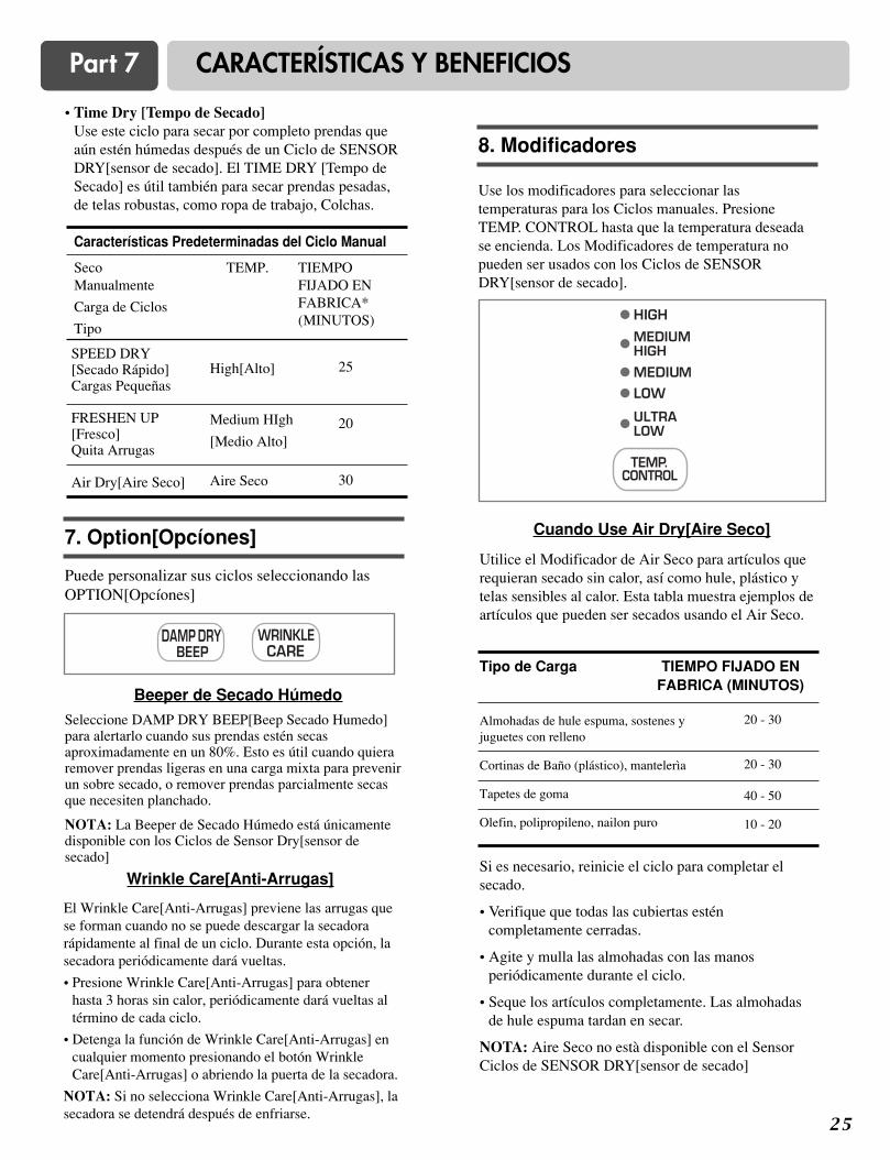
2 5
Part 7 CARACTERÍSTICAS Y BENEFICIOS
Seleccione DAMP DRY BEEP[Beep Secado Humedo]para alertarlo cuando sus prendas estén secasaproximadamente en un 80%. Esto es útil cuando quieraremover prendas ligeras en una carga mixta para prevenirun sobre secado, o remover prendas parcialmente secasque necesiten planchado.
NOTA: La Beeper de Secado Húmedo está únicamentedisponible con los Ciclos de Sensor Dry[sensor desecado]
• Time Dry [Tempo de Secado]Use este ciclo para secar por completo prendas queaún estén húmedas después de un Ciclo de SENSORDRY[sensor de secado]. El TIME DRY [Tempo deSecado] es útil también para secar prendas pesadas,de telas robustas, como ropa de trabajo, Colchas.
Beeper de Secado Húmedo
El Wrinkle Care[Anti-Arrugas] previene las arrugas quese forman cuando no se puede descargar la secadorarápidamente al final de un ciclo. Durante esta opción, lasecadora periódicamente dará vueltas.
• Presione Wrinkle Care[Anti-Arrugas] para obtenerhasta 3 horas sin calor, periódicamente dará vueltas altérmino de cada ciclo.
• Detenga la función de Wrinkle Care[Anti-Arrugas] encualquier momento presionando el botón WrinkleCare[Anti-Arrugas] o abriendo la puerta de la secadora.
NOTA: Si no selecciona Wrinkle Care[Anti-Arrugas], lasecadora se detendrá después de enfriarse.
Wrinkle Care[Anti-Arrugas]
Utilice el Modificador de Air Seco para artículos querequieran secado sin calor, así como hule, plástico ytelas sensibles al calor. Esta tabla muestra ejemplos deartículos que pueden ser secados usando el Air Seco.
Cuando Use Air Dry[Aire Seco]
Tipo de Carga TIEMPO FIJADO ENFABRICA (MINUTOS)
Puede personalizar sus ciclos seleccionando lasOPTION[Opcíones]
7. Option[Opcíones]
Use los modificadores para seleccionar lastemperaturas para los Ciclos manuales. PresioneTEMP. CONTROL hasta que la temperatura deseadase encienda. Los Modificadores de temperatura nopueden ser usados con los Ciclos de SENSORDRY[sensor de secado].
8. Modificadores
Características Predeterminadas del Ciclo Manual
SecoManualmente
Carga de Ciclos
Tipo
TEMP. TIEMPOFIJADO ENFABRICA*(MINUTOS)
SPEED DRY [Secado Rápido]Cargas Pequeñas
FRESHEN UP[Fresco]Quita Arrugas
Air Dry[Aire Seco]
High[Alto]
Medium HIgh
[Medio Alto]
Aire Seco
25
20
30
Almohadas de hule espuma, sostenes yjuguetes con relleno
Cortinas de Baño (plástico), mantelerìa
Tapetes de goma
Olefin, polipropileno, nailon puro
20 - 30
20 - 30
40 - 50
10 - 20
Si es necesario, reinicie el ciclo para completar elsecado.
• Verifique que todas las cubiertas esténcompletamente cerradas.
• Agite y mulla las almohadas con las manosperiódicamente durante el ciclo.
• Seque los artículos completamente. Las almohadasde hule espuma tardan en secar.
NOTA: Aire Seco no està disponible con el SensorCiclos de SENSOR DRY[sensor de secado]

2 6
Part 7 CARACTERÍSTICAS Y BENEFICIOS
El perchero de secado viene incluido en su secadora.Retire y deseche el material envolvente antes deusarlo. Use el RACK DRY[Secado con Parrilla] paraartículos que usted no quiera secar dando vueltas, asícomo suéteres. Cuando use el perchero de secado concalor, el aire caliente dentro de la secadora fluirá enuna trayectoria concentrada que permitirá un secadouniforme y eficiente. Utilice el Tempo de Secado paradeterminar el tiempo de secado deseado.
Para usar el RACK DRY [Secado en Parrilla]• Abra la puerta de la Secadora.
• No quite la malla de pelusa.
• Coloque la parrilla de la secadora sobre la parteinferior de la abertura de la puerta. Recargue laparrilla sobre la saliente trasera de la secadora.Presione sobre el marco frontal para asegurarla sobrela malla para pelusa.
• Coloque los artículos mojados sobre la parrilla. Dejeespacios alrededor de los artículos para que circule elaire. La parrilla no se mueve, pero el tambor rotará.Asegúrese que los artículos no cuelguen de losbordes o se metan entre las rejas de la parrilla
• Cierre la puerta.
9. Rack Dry[Secado con Parrilla]
La BEEPER[Alarma] controla el volumen de laseñal que se emite cuando se presiona algún botónen el panel de control y cuando la conclusión dealgún ciclo es indicado. Presione BEEPER[Alarma]para ajustar el nivel del sonido o para apagar laseñal.
10. BEEPER[Alarma]
Esta opciòn sòlo puede ser utilizada con NORMA,HEAVY DUTY, CONNTON/TOWELS [TRABAJOHEAVY DUTY, ALGODÓN/TOALLAS], y ciclos
Esta opciòn reduce algunos tipos de bacterias.
El proceso ANTIBACTERIAL produce altastemperaturas durante el ciclo.
NOTA: no use este ciclo en prendas delicadas.
11. ANTI BACTERIAL
Programe su combinación favorita de característicasy guárdelas aquí para ejecutarlo con un sólo toque.
Para guardar un PROGRAMA PERSONAL.
1)Seleccione el ciclo
2Cambie el Dry Level [Nivel de Secado] y elCONTROL de TEMP.
3)Seleccione la OPTION[Opción] de su preferencia.
4)Presione y sostenga CUSTOM PROGRAM
Para volver a utilizar su programa personalpreviamente guardado presione el botón deCUSTOM PROGRAM y luego presioneStart/Pause[Inicio/Pausa].
NOTA: Verifique la malla para pelusa y eliminecualquier pelusa acumulada de los artículossecados en el perchero.
12. CUSTOM PROGRAM
Artículossugeridos parasecado conParrilla
Temperatura TiempoSugerido*(Minutos)
Artículos lavables de lana(doble a la forma de laparrilla y déjelo en posiciónplana sobre) la parrilla).
Low[Bajo] 20
20/30
50/30
50
20
Low/Ultra Low[Bajo/Ultra Bajo]
Air Dry[Aire Seco]Ultra Low[Ulta Bajo]
Air Dry[Aire Seco]
Air Dry[Aire Seco]
Juguetes Rellenos(Algodón o relleno de fibrade poliéster).
Juguetes Rellenos(rellenos de hule-espuma).
Almohadas de Hule-Espuma
Zapatos Tenis
* Reinicie el tiempo lo necesario para completar el secado.
• Seleccione RACK DRY[Secado en Parrilla] yMORE TIME[Más Tiempo.] o LESS TIME[MenosTiempo.] Si es necesario, reinicie el tiempo paracompletar el secado. Refiérase a la tabla anterior.
• Seleccione la temperatura deseada de acuerdo con lastelas en su carga presionando TEMP. CONTROL[Control de Ttemp.] (Secado con Aire- Ultra Baja-Baja). Artículos que contengan espuma, hule, oplástico deben ser secados en el tendedero outilizando las temperaturas del Secado con Aire.Refiérase a la siguiente tabla.
• Encienda la secadora.
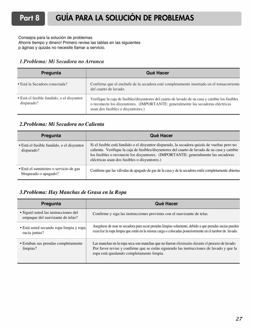
2 7
Part 8 GUÍA PARA LA SOLUCIÓN DE PROBLEMAS
Consejos para la solución de problemasAhorre tiempo y dinero! Primero revise las tablas en las siguientesp áginas y quizás no necesite llamar a servicio.

2 8
Part 8 GUÍA PARA LA SOLUCIÓN DE PROBLEMAS
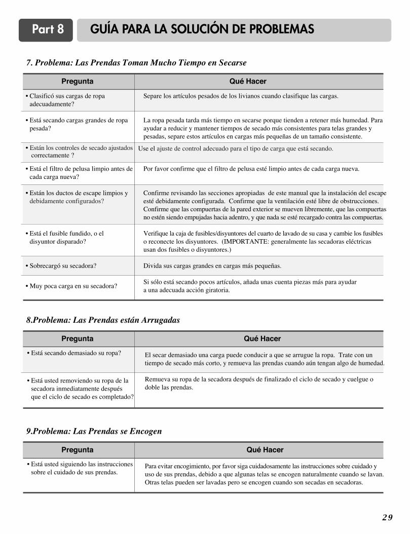
2 9
Part 8 GUÍA PARA LA SOLUCIÓN DE PROBLEMAS
3 0
GARANTÍA LIMITADA DE LA SECADORA LG-USA
1-800-243-0000
1-800-243-0000