sealed air fawkner, vic 3060 - shrinkmachines.com.au
TRANSCRIPT

This risk control recommendation is intended for guidance purpose only. Failing to ensure professional installation of the correct equipment which has regard to the specific circuit design and operation of the plant on which it is being installed may create a safety hazard. Accordingly, Venus Automation is not liable for any loss or injury, whether direct or indirect, flowing from the incorrect product installation.
Sealed Air Pty Ltd. Fawkner, VIC 3060
HAZARD IDENTIFICATION, RISK ASSESSMENT
AND RISK CONTROL
RECOMMENDATIONS FOR
L BAR SEALER WRAPPER & SHRINK TUNNEL
Sealed Air
Fawkner, Vic 3060

Company: Sealed Air Page 2 of 28 Document: Risk Assessment for Wrapper L Bar Sealer & Shrink Tunnel_V2 Date: 13th November 2018
Venus Automation
Created
Raju Kotecha B.E (Elect) MIE Aust CP Eng
Sealed Air Pty Ltd.
Accepted
Mr. Oliver Frobose Company Secretary
DOCUMENT VERSION
Version
Date
Author
Description
V1
4th October 2018
Raju Kotecha
Initial issue (V1)
V2 13th November 2018 Raju Kotecha Changes in report format as per customer’s request
Disclaimer:
(1) Is should be noted that this report was prepared by Venus Automation Pty Ltd for Sealed Air (“the customer”) in accordance with the scope of work and specific requirements agreed between Venus Automation and the customer. This report was prepared with information supplied by customer at the time of inspection and preparation of the report. Venus Automation or any of their employees cannot be held responsible for any omissions resulting from information not provided by sealed air.
(2) Please don’t expect to find all comments regarding a specific area of concern to be noted in one
particular area or under one heading, as other comments associated are most certainly to be found throughout the report or links associated to this report. Reference to part only of the report will be seen as selective comment and is not acceptable or adequate for ascertaining findings.
Raju Kotecha B.E.(Elect) MIE Aust CP Eng CESE (Certified Electrical Safety Engineer & Certified Trainer) TÜV SAAR. Venus Automation Pty Ltd. M: 0476 007 577 E: [email protected]

Company: Sealed Air Page 3 of 28 Document: Risk Assessment for Wrapper L Bar Sealer & Shrink Tunnel_V2 Date: 13th November 2018
Table of contents
1.11 Scope……….…………………………………………………………………………………. 4 1.12 References………………………………………………………………………………….. 4 1.1 Summary of Statutory requirements- VICTORIA……. ………………….. 5
1.11 Date of Assessment……………………………………………………………………… 7 1.12 Consultations………………………………………………………………………………. 7 1.13 Reason for Risk Assessment……………………………………………………….. 7 1.14 Machine description….………………………………………………………………… 7 1.15 Intended use and limitations……………………………………………………….. 7 1.16 Accidents or incidents …………………………………………………………………. 7 1.17 Machine energy sources………………………………………………………………. 7 1.18 Technical information………………………………………………………………….. 7 1.19 Risk Analysis …………………………………………………………………………………. 7 1.2 L Bar Sealer Machine: Mechanical Hazard identification, Risk Assessment and Risk control recommendations……………………………………………………………… 8..17 1.3 Shrink Tunnel Machine: Machine photo, Hazard identification, Risk Assessment and Risk control recommendations……………………………………………………… 18..21 1.4 Maintenance and LOTO………………………………………………………………….. 22 1.5 Residual Risk……………………………………………………………………………………. 22 1.6 Electrical schematics………………………………………………………………………. 23 1.7 Summary of Category requirements………………………………………………. 25
----------------------------------------------------------------------------------------------------------------------------

Company: Sealed Air Page 4 of 28 Document: Risk Assessment for Wrapper L Bar Sealer & Shrink Tunnel_V2 Date: 13th November 2018
Scope: The scope of this report is for hazard identification, risk assessment and risk control recommendations for
WRAPPER SLCT-FA16004 (L Bar Sealer) and Shrink Tunnel Machine (SLCT-FT-4225) as per AS 4024.1-2014. (Machinery safety standard). This does not include identifying hazards and risk control recommendations for explosive atmosphere.
This report and risk control recommendations are restricted to the guarding and structural requirements
and recommendations on safety control system for the machine and DO NOT include detailed analysis of safe operating procedure or Information handbooks.
References:
1. VIC Work Health and Safety Act 2004 2. VIC Work Health and Safety Regulation 2017 3. AS 4024.1-2014 Safety of machinery Standard

Company: Sealed Air Page 5 of 28 Document: Risk Assessment for Wrapper L Bar Sealer & Shrink Tunnel_V2 Date: 13th November 2018
1.1 Summary of Statutory Requirements- Victoria
Work Health and Safety Act 2004 The Work Health and Safety Act 2011 provides an obligation on employers, machine designers, manufactures and suppliers to ensure that machinery designed, manufacture or supplied is “safe and without risk to health when properly used.” Work Health & Safety Regulation 2017 Work Health and Safety Regulation has come into effect as of 18th June 2017. This regulation is binding to all states and territories of Australia. This regulation details the various responsibilities application to employers, designers, manufacturers and suppliers of plant (including machines) including identifying hazards and controlling risks. Risk Assessment process: The Risk Assessment process focuses on the risk control measures deemed to be necessary to ensure that any risk from exposure to the identified hazards associated with the normal use of this machine have been minimized. The Risk Assessment combines the criteria of hazard identification, risk assessment and application of risk control measures to ensure than identified hazards are eliminated, or if this is not practicable, to minimize the risks as far as is reasonably practicable. Hazard Identification: Hazard identification refers to identifying all reasonably foreseeable situations, or events, which could cause injury or illness. This hazard identification process employed for this report involved visual inspection of the machine and consultation with relevant personnel. Risk Assessment: The hazard identification and consequent assessment of the risks associated with those hazards are as detailed in the “Risk Assessment” table below. The risk associated with each hazard has been assessed to determine the appropriate safety category required, as prescribed in AS 4024.1501-2006: Design of safety related parts of control Systems-General principles for design. The risk estimation has been determined following the format of Australian Standard AS 4024.1301-2006 Principles of risk assessment, considering the combined factors of severity of possible harm (S), probability of occurrence of harm (P) and frequency and/or duration of exposure (F).

Company: Sealed Air Page 6 of 28 Document: Risk Assessment for Wrapper L Bar Sealer & Shrink Tunnel_V2 Date: 13th November 2018
Risk Control and Recommendations: The recommendations for risk control are given in accordance with the ‘hierarchy of risk control’ methods (Elimination, Substitution, Isolation, Engineering, Administrative controls and Personal Protective equipment) and also consideration of what is ‘reasonably practicable’ in terms of implementation of risk control measures.
Risk level associated with hazards determined with AS 4024.1503-2014.
Risk Control and Recommendations: The recommendations for risk control are given in accordance with the ‘hierarchy of risk control’ methods (Elimination, Substitution, Isolation, Engineering, Administrative controls and Personal Protective equipment) and also consideration of what is ‘reasonably practicable’ in terms of implementation of risk control measures. It is important to understand and follow below shown hierarchy of controls and ensure that all reasonably practicable options have been implemented before proceeding to the lower rung.

Company: Sealed Air Page 7 of 28 Document: Risk Assessment for Wrapper L Bar Sealer & Shrink Tunnel_V2 Date: 13th November 2018
1.11 Date of Assessment: 28th August 2018
1.12 Consultations with and Positions:
Mr. Ken Koh (Account Representative, National Technical Support)
1.13 Indicate Why Risk Assessment was Initiated: To ensure machine meets AS 4024.1:2014 and NSW WHS Act and Regulation 2011.
1.14 Equipment description Wrapper SLCT-FA16004 (L Bar Sealer) machine is used to dispense shrink wrap, cut shrink wrap and covers the product with shrink wrap on both sides.
1.15 Intended use and limits of machinery Machine is intended to cut shrink wrap with heated wire before shrinking the wrap on to the product. Machine must be strictly used as per manufacturer’s guidelines.
1.16 Accidents or incidences: No known accidents or incidences
1.17 Energy sources on the machine 230VAC, 1 Phase Electrics, Pneumatics for L Bar Sealer 415VAC, 3 Phase for Shrink Tunnel Machine
1.18 Technical information: Machine layout Electrical Schematics Pneumatic schematics Hydraulic schematics Electrical schematic is made available.
1.19 Risk Analysis:
Determination of the Limits of Machinery i. Phases of Machine Life:
Both machines are brand new in excellent condition. It will be operational for many more years.
ii. Limits of Machinery: Machine dispenses shrink wrap, cuts the wrap to size and then wraps the product with shrink wrap on both sides for various size products (please refer to machine operation manual). It must be strictly used as per manufacturer’s guidelines.
iii. Range of Foreseeable Uses Machine can be used for wrapping various products subject to manufacturer’s guidelines and operating manual.
iv. Anticipated Level of Training Low level of training is required to operate the machine.
v. Exposure of Other Persons Various people could be working in the vicinity and hence exposure to hazards is quite possible.
Company: Sealed Air Page 8 of 28 Document: Risk Assessment for Wrapper L Bar Sealer & Shrink Tunnel_V2 Date: 13th November 2018
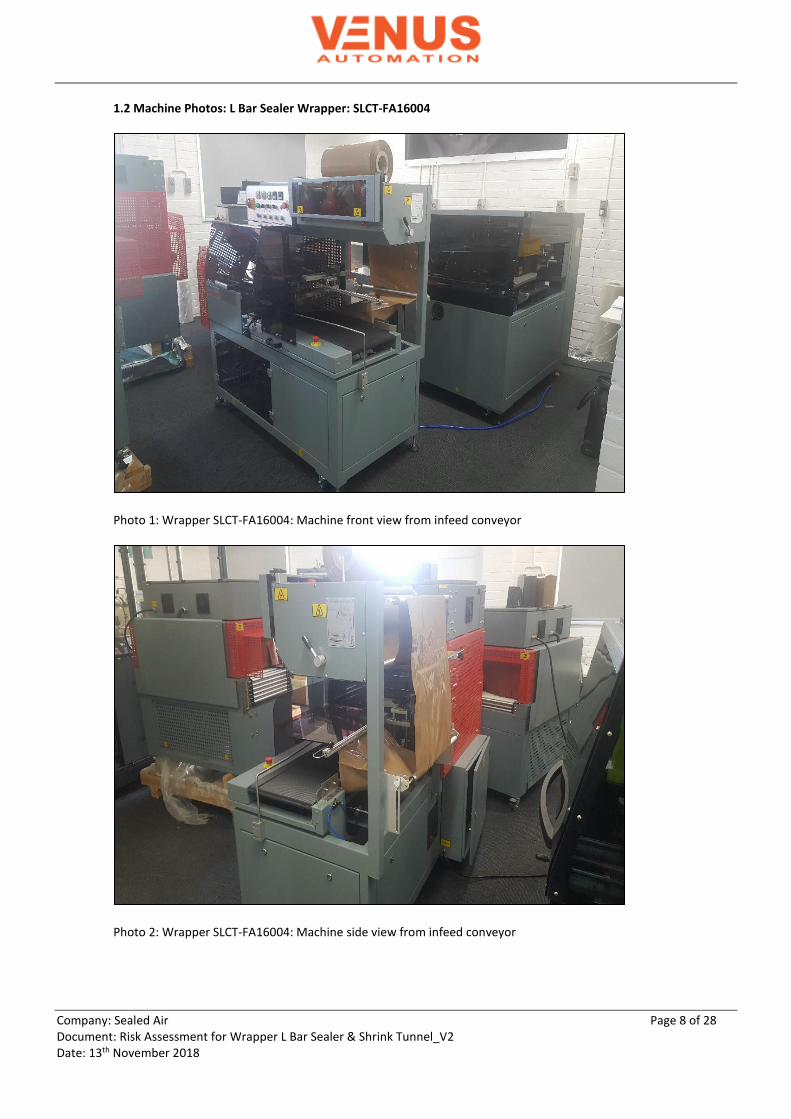
1.2 Machine Photos: L Bar Sealer Wrapper: SLCT-FA16004
Photo 1: Wrapper SLCT-FA16004: Machine front view from infeed conveyor
Photo 2: Wrapper SLCT-FA16004: Machine side view from infeed conveyor

Company: Sealed Air Page 9 of 28 Document: Risk Assessment for Wrapper L Bar Sealer & Shrink Tunnel_V2 Date: 13th November 2018
Hazard Identification and existing situation: Wrapper SLCT-FA16004
Mechanical hazard identification Pre-control Risk Assessment
No. Describe the Hazard
What is it? Where is? How is it?
What is the consequence of the hazard?
Describe damage and/or injury
Raw Risk Rating
(No control)
Risk Category/Pl
Existing Control Measures
& Recommendations
S
F
P
H1
Photo 3: Wrapper SLCT-FA16004: Perforator wheels with opened guard
Hazard Description: Pins on perforation wheels Location: Main machine Energy source: Manually operated
Unintentional exposure to pins on moving perforation wheels could cause stabbing & puncture injuries.
S1
F2
P1
-/ Pl b
Existing: (1) Gap in guarding above machine allows for access to
the perforation wheel hazard.
Photo 4: Wrapper SLCT-FA16004: Gap in guarding above existing guard

Company: Sealed Air Page 10 of 28 Document: Risk Assessment for Wrapper L Bar Sealer & Shrink Tunnel_V2 Date: 13th November 2018
(2) Front hinged guard is interlocked with Omron D40A-1C2, non-contact, magnetic sensor which is wired in 1NC contact to SIRON Y 400-P standard relay.
Photo 5: WRAPPER SLCT-FA16004: Perforation wheels behind closed interlocked guard
Photo 6: Wrapper SLCT-FA16004: Omron D40A-1C2 guard switch on perforator guard

Company: Sealed Air Page 11 of 28 Document: Risk Assessment for Wrapper L Bar Sealer & Shrink Tunnel_V2 Date: 13th November 2018
Recommendations: (1) It is recommended to cover gap in guarding (photo 4)
above the perforation wheels guard. If this is not practicable then operators/maintenance personnel should be provided with appropriate training/PPE to guard against the residual risk.

Company: Sealed Air Page 12 of 28 Document: Risk Assessment for Wrapper L Bar Sealer & Shrink Tunnel_V2 Date: 13th November 2018
H2
Photo 7: Wrapper SLCT-FA16004: View of L Seal-A-Bar with open interlocked guard.
Hazard Description: L Seal-A-Bar with heated wire cutter and pneumatically driven movement. Location: Main machine Energy source: Pneumatics for L bar sealer jaw Electrics for heated cutter wire
Unintentional exposure to pneumatically driven L Seal-A-Bar with heated wire cutter can cause severe crushing, pinch point and burn injuries.
S2
F2
P1
3/Pl d
Existing: (1) Front hinged guard is interlocked with Pilz Psen me4.1
guard switch which is wired in 1NC contact to safety relay.
Photo 8: Wrapper SLCT-FA16004: View with closed interlocked guard.

Company: Sealed Air Page 13 of 28 Document: Risk Assessment for Wrapper L Bar Sealer & Shrink Tunnel_V2 Date: 13th November 2018
Additional Recommendations on following pages:
Photo 9: Wrapper SLCT-FA16004: Pilz Psen me4.1/4as safety switch on interlocked guard
Recommendations: (1) It is recommended upgrading Pilz Psen me4.1 (see
photo 9) guard interlock from 1NC contact to 2NC contacts and monitored by safety controller. Activation of guard Interlock should de-energize contactor KM1 and pneumatic energy source through safety pneumatic valve. The NC feedback contact of contactor KM1 and safety pneumatic valve be monitored by Wieland SNA 4043K-A safety relay.

Company: Sealed Air Page 14 of 28 Document: Risk Assessment for Wrapper L Bar Sealer & Shrink Tunnel_V2 Date: 13th November 2018
Additional information: L Bar Sealer Wrapper: SLCT-FA16004
Photo 10: Wrapper SLCT-FA16004: Emergency stop near infeed conveyor
Photo 11: Wrapper SLCT-FA16004: Pneumatic air regulator
Existing Emergency stop wired in 1NC single channel in series with guard switches to safety relay.
Lockable pneumatic regulator for machine air supply.
Existing pneumatic air valve is not safety rated.

Company: Sealed Air Page 15 of 28 Document: Risk Assessment for Wrapper L Bar Sealer & Shrink Tunnel_V2 Date: 13th November 2018
Photo 12: Wrapper SLCT-FA16004: Front cover control panel with emergency stop and lockable electrical isolation switch
Photo 13: Wrapper SLCT-FA16004: Over view of electrical panel with interlocked guard
Existing emergency stop is wired in 1NC single channel in series with guard switches to safety relay.
Lockable electrical isolation switch
Electrical panel is interlocked with Omron non-contact switch wired in single channel to safety relay
Omron non-contact guard switch wired in 1NC contact to interposing SIRON Y400-P standard relay.
Wieland safety controller monitoring Emergency stop, and Guard interlocks wired in 1NC contacts in series.

Company: Sealed Air Page 16 of 28 Document: Risk Assessment for Wrapper L Bar Sealer & Shrink Tunnel_V2 Date: 13th November 2018
Photo 14: Wrapper SLCT-FA16004: Electrical control panel
Existing Situation:
Emergency stops (see photos 13 and 15) are wired in 1NC contact in series with 6 x Guard interlocks to Wieland SNA 4043 K-A safety relay. This doesn’t meet requirements of Clause 79 of Victorian WHS Regulation 2017 which demands Emergency stop be not affected by electrical or electronic malfunction. As per electrical schematics, activation of Emergency stop de-energizes SNA 4043K-A safety which de-energizes standard relay KA6 which is not a safety rated device. The NO contact of KA6 energizes contactor KM1 and pneumatic controls. The NC feedback contact of KM1 is not monitored by safety relay. Existing pneumatic valve (see photo 14) is not safety rated. In the event of a pneumatic failure, it is possible for the pneumatically driven L Seal-A-Bar to fall under gravity.
Additional Recommendations for L Bar Sealer Machine
1) It is recommended upgrading existing Emergency stops from 1NC contact to 2NC contacts and monitored by safety controller. Activation of Emergency stop should de-energize contactor KM1 and pneumatic energy source through safety pneumatic valve. The NC feedback contact of contactor KM1 and safety pneumatic valve must be monitored by Wieland SNA 4043K-A safety relay. A manual reset button monitored by safety controller and providing clear view of the hazardous area must be provided on the operator panel.
2) It is recommended providing safety rated pneumatic valve monitored by safety controller. The NC feedback contact of the safety pneumatic valve must be monitored by Wieland SNA 4043K-A safety relay. A manual reset button monitored by safety controller and providing clear view of the hazardous area must be provided on the operator panel.
3) Maintenance and removal of fixed guards should be strictly done by trained personnel and/or Sealed air
technicians.
NC contact of Fuji contactor KM1 is not monitored in feedback circuit of safety controller

Company: Sealed Air Page 17 of 28 Document: Risk Assessment for Wrapper L Bar Sealer & Shrink Tunnel_V2 Date: 13th November 2018
4) Supervisors, employees, casual workers, cleaners and anyone likely to be working with the machine should be trained and provided with information on the nature of the hazards and residual risk associated with the machinery. Machine must be strictly used as per operating manual.
5) Supervisors, employees, casual workers, cleaners and anyone likely to be working with the machine should be
provided with appropriate PPE. 6) All signage to comply with the requirements of AS 1319-1994. Safety signs for the occupational environment. Note: 1) All access gates and gaps in guarding should be covered as per Clause 77 of Victorian Workplace Health and
Safety Regulation 2017. It stipulates that permanently fixed physical barrier should be implemented where access is not required for operation, cleaning and maintenance. Interlocking followed by presence sensing safeguarding of all guards (AS 4024.1601-2006) should be implemented where access is required for operation, cleaning and maintenance. If this is not practicable then the guard should be attached to the machine with fasteners which are removable only with the use of a tool. Access to this tool should be controlled by procedure. Bearing in mind that procedures are administrative risk control measures and as such, interlocking should be implemented where practicable (Clause 4.8, 4.9 and 6.4.4 of AS 4024.1601-2006).

Company: Sealed Air Page 18 of 28 Document: Risk Assessment for Wrapper L Bar Sealer & Shrink Tunnel_V2 Date: 13th November 2018
Machine Photos: Shrink Tunnel Machine (SLCT-FT 4225)
Photo 15: Shrink Tunnel machine: Front view
Photo 16: Shrink Tunnel Machine: Name plate details.
Energy source: 415 V, 3 Phase electrics
Fixed guard fastened with bolts which require tool for removal.

Company: Sealed Air Page 19 of 28 Document: Risk Assessment for Wrapper L Bar Sealer & Shrink Tunnel_V2 Date: 13th November 2018
Hazard Identification and existing situation: Shrink Tunnel machine:
Mechanical hazard identification Pre-control Risk Assessment
No. Describe the Hazard
What is it? Where is? How is it?
What is the consequence of the hazard?
Describe damage and/or injury
Raw Risk Rating
(No control)
Risk Category/Pl
Existing Control Measures
& Recommendations
S
F
P
1
Photo 17: Shrink Tunnel Machine: View from outfeed side Hazard Description: Heated components inside shrink tunnel Location: Shrink Tunnel machine Energy source: Electrical/heat
Unintentional exposure to inside of shrink tunnel machine can cause burn injuries.
S2
F1
P1
2/ Pl c
Existing: (1) Product to be shrink wrapped is
manually/automatically (from other machine) on infeed conveyor of Shrink Tunnel machine. It comes out on the outfeed side of the machine. Operator/people in the vicinity can get exposed to the hazard of hot air/high temperature by putting hand/limbs inside the shrink tunnel.
(2) Front fixed guard is fastened with bolts which require
tool for removal

Company: Sealed Air Page 20 of 28 Document: Risk Assessment for Wrapper L Bar Sealer & Shrink Tunnel_V2 Date: 13th November 2018
Additional recommendations on following pages
Photo 18: Shrink Tunnel machine: Front view Recommendations: (1) Nil
Company: Sealed Air Page 21 of 28 Document: Risk Assessment for Wrapper L Bar Sealer & Shrink Tunnel_V2 Date: 13th November 2018
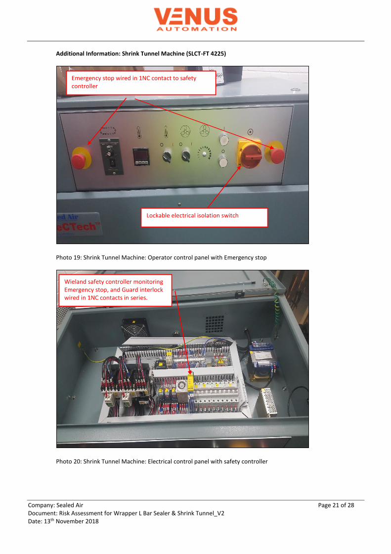
Additional Information: Shrink Tunnel Machine (SLCT-FT 4225)
Photo 19: Shrink Tunnel Machine: Operator control panel with Emergency stop
Photo 20: Shrink Tunnel Machine: Electrical control panel with safety controller
Wieland safety controller monitoring Emergency stop, and Guard interlock wired in 1NC contacts in series.
Emergency stop wired in 1NC contact to safety controller
Lockable electrical isolation switch

Company: Sealed Air Page 22 of 28 Document: Risk Assessment for Wrapper L Bar Sealer & Shrink Tunnel_V2 Date: 13th November 2018
Existing Situation: Interlocked guards: Machine’s electrical panel is interlocked with Omron, non-contact, magnetic sensor wired in 1NC contact to SIRON Y 400-P standard relay. Guard interlock is wired in series with 2 x Emergency stops to Wieland SNA 4043K-A safety relay. Wieland SNA 4043K-A safety relay de-energizes standard relay KA1 which is not a safety rated device. The NO contact of KA1 energizes main contactor KM0. The NC feedback contact of KM0 is not monitored by safety relay. Emergency stop: Machine is provided with 2 x Emergency stops on the operator control panel. Emergency stops are wired in 1NC contact in series with guard interlock to Wieland SNA 4043K-A safety relay. Wieland SNA 4043K-A safety relay de-energizes standard relay KA1 which is not a safety rated device. The NO contact of KA1 energizes main contactor KM0. The NC feedback contact of KM0 is not monitored by safety relay. Recommendations: It is recommended upgrading existing Emergency stops from 1NC contact to 2NC contacts and monitored by Safety controller to ensure compliance with Clause 79 of Victorian WHS Regulation 2017 which demands Emergency stop should not be affected by electrical or electronic malfunction. It is recommended that NC feedback contact of contactor KM0 be monitored by Wieland SNA 4043K-A safety relay. 1.3 Maintenance and LOTO: Both machines are powered with removable power plug socket for electrical energy source. There is evidence of lockable electrical isolation switch on operator panel of both machines. There is evidence of lockable pneumatic regulator for isolation of pneumatic energy source for L Bar sealer machine. It is recommended to ensure machines are fully isolated from all energy sources during maintenance. Lockable isolation switch is mandatory as per requirement of Clause 5.1 of AS 4024.1603-2006. 1.4 Residual risk: It is recommended for operators, maintenance personnel to be advised of following residual risk. (1) Ergonomic risks during manual handling of shrink wrap rolls. (2) Stored heat energy in L Bar Seal Jaw and in the Shrink Tunnel. 1.5 Other hazards: Electrical hazards: None identified Hazards generated by noise: None identified Hazards generated by vibration: None identified. Hazards generated by materials and substances: None identified.

Company: Sealed Air Page 23 of 28 Document: Risk Assessment for Wrapper L Bar Sealer & Shrink Tunnel_V2 Date: 13th November 2018
1.6 Electrical Schematics:

Company: Sealed Air Page 24 of 28 Document: Risk Assessment for Wrapper L Bar Sealer & Shrink Tunnel_V2 Date: 13th November 2018
Electrical schematic: Shrink Tunnel Machine Page 1 of 2

Company: Sealed Air Page 25 of 28 Document: Risk Assessment for Wrapper L Bar Sealer & Shrink Tunnel_V2 Date: 13th November 2018
Electrical schematic: Shrink Tunnel Machine Page 2 of 2

Company: Sealed Air Page 26 of 28 Document: Risk Assessment for Wrapper L Bar Sealer & Shrink Tunnel_V2 Date: 13th November 2018
1.7 Annexure A: Summary of Requirement for Categories (Source AS 4024.1501-2006) Category Summary requirements System behavior (see Note 2) Principles to achieve safety
Category B Safety-related parts of control systems and/or their protective equipment, as well as their components, shall be designed, constructed, selected, assembled and combined in accordance with relevant standards so that they can withstand the expected influence.
The occurrence of a fault can lead to loss of the safety function.
Mainly characterized by selection of components
Category 1 Requirements of B shall apply. Well-tried components and well-tried safety principles shall be used.
The occurrence of a fault can lead to loss of the safety function, but the probability of occurrence is lower than for category B.
Category 2 Requirements of B and the use of well-tried safety principles shall apply.
The occurrence of a fault can lead to loss of the safety function between the checks.
Mainly characterized by structure
Category 3 Requirements of B and the use of well-tried safety principles shall apply. Safety Related parts shall be designed so that- A single fault in any of these parts does not lead to loss of the safety function; and Whenever reasonably practicable the single fault is detected.
When a single fault occurs, the safety function is always performed. Some but not all faults will be detected. Accumulation of undetected faults can lead to loss of the safety function
Mainly characterized by structure

Company: Sealed Air Page 27 of 28 Document: Risk Assessment for Wrapper L Bar Sealer & Shrink Tunnel_V2 Date: 13th November 2018
Category 4
Requirements of B and the use of well-tried safety principles shall apply. Safety Related parts shall be designed so that- A single fault in any of these parts does not lead to loss of the safety function; and The single fault is detected at or before the next demand upon the safety function. If this is not possible, then an accumulation of faults shall not lead to loss of the safety function.
When a single fault occurs, the safety function is always performed. The faults will be detected in time to prevent loss of the safety function.
Mainly characterized by structure
