se si-1 - honeywell integrated security · the se si-1 sensor interface module manufactured by...
TRANSCRIPT

SE SI-1
PROXIMITY SYSTEM
INSTALLATION MANUAL
WestinghouseSecurity Electronicsan ISO 9001 certified company
5452 Betsy Ross DriveSanta Clara, CA 95054-1184(408) 727-5170FAX (408) 727-6707
P/N 66108283001, Rev. B

© 1996 Westinghouse Security ElectronicsAll rights reserved. Printed in the United States of America.
WARRANTY
Westinghouse Security Electronics (WSE) warrants to the original user of the equipment manufactured by WSE
as described herein to be free from defects in material and workmanship for a period of one year from the date
of purchase by such user or fifteen (15) months from the date of shipment from the factory, whichever is sooner
(command key / magnetic stripe card warranties differ�see below), provided:
I WSE has been notified within such period by return of any alleged defective equipment, free and clear
of any liens and encumbrances to WSE or its authorized dealer at the address specified,
transportation prepaid; and
II the equipment has not been abused, misused or improperly maintained and/or repaired during such
period; and
III such defect has not been caused by ordinary wear and tear; and
IV such defect is not a result of voltage surges/brownouts, lightning, water damage/flooding, fire,
explosion, earthquakes, tornadoes, acts of aggression/war, or similar phenomena; and
V accessories used as integral to WSE systems have been approved by WSE (e.g., coaxial cables,
batteries, etc.); and
VI the equipment has been installed, the installation supervised or installation tested by an authorized
WSE dealer.
WSE shall at its option, either repair or replace, free of charge, the equipment found, upon WSE's inspection to
be so defective, or if agreed upon, refund the purchase price, less a reasonable allowance for depreciation, in
exchange for the equipment.
WSE makes no other warranty, and all implied warranties including any warranty of merchantability or fitness for
a particular purpose are limited to the duration of the expressed warranty as set forth above.
WSE's maximum liability hereunder is limited to the purchase price of the equipment. In no event shall WSE be
liable for any consequential, indirect, incidental or special damages of any nature arising from the sale or use of
the equipment.
Some states do not allow limitations on incidental or consequential damages or how long an implied warranty
lasts, so the above limitations may not apply. This warranty gives specific legal rights; however, other rights which
vary from state to state, may pertain.
Analog command keys are warranted for 5 years; digital command key / magnetic stripe card warranties vary�
See product literature.
Important
The information provided in this manual is believed to be accurate and reliable. However, WSE assumes no
responsibility for any errors that may appear. Possession of this manual does not imply the granting of licenses
to make or sell equipment or software constructed according to descriptions provided.

FEDERAL COMMUNICATIONS COMMISSION RADIO FREQUENCYINTERFERENCE STATEMENT
The SE SI-1 Sensor Interface Module manufactured by Westinghouse Security Electronics has been tested
and found to comply with the limits for a Class A digital device, pursuant to Part 15 of the FCC Rules. These
limits are designed to provide reasonable protection against harmful interference in a residential installation.
This equipment generates, uses, and can radiate radio frequency energy and, if not installed and used in
accordance with the instructions herein, may cause harmful interference to radio communications. If this
equipment does cause harmful interference to radio or television reception, consult the dealer or an
experienced radio/television technician for correction.
The user may find helpful the following booklet, prepared by the Federal Communications Commission: "How
to Identify and Resolve Radio/TV Interference Problems." This booklet is available from the US Government
Printing Office, Washington, DC 20402, stock number: 004-000-0035-4.
UL-294 Notice
The SI-1 Sensor Interface Module is UL-294 listed and may be used in a UL-294 listed access control
system. All system components must be UL-294 listed and installed according to manufacturers'
instructions to comply with UL requirements.
294


v
Table of ContentsSECTION 1: INTRODUCTION ................................................................ 1-1
INTRODUCTION ......................................................................................... 1-1Scope ................................................................................................... 1-1
SECTION 2: MOUNTING ..................................................................... 2-1INTRODUCTION ......................................................................................... 2-1MOUNTING THE ENCLOSURE .................................................................. 2-1MOUNTING THE SI-1 ................................................................................. 2-2MOUNTING THE SE 28XX SENSORS ....................................................... 2-3
SECTION 3: WIRING ......................................................................... 3-1INTRODUCTION ......................................................................................... 3-1
Routing Coaxial Cables ......................................................................... 3-1Inserting Coax Cable Connectors (Figure 3-1) ...................................... 3-1Data and Power Network Wiring........................................................... 3-3Connecting Cable Shield to the Enclosure ............................................. 3-3Installing the Conductors in J2 and/or J3 .............................................. 3-6Power Inserter Wiring ........................................................................... 3-8
SECTION 4: SE 422 SETUP .............................................................. 4-1INTRODUCTION ......................................................................................... 4-1
Database Setup from the Front Panel................................................... 4-1Database Setup from the Terminal........................................................ 4-2
ENTERING THE SE 1050 COMMAND KEYS ............................................. 4-3INSTALLATION CHECKLIST....................................................................... 4-4DIAGNOSTIC CHECKS .............................................................................. 4-4
LED Diagnostic Checks ........................................................................ 4-6
APPENDIX: SPECIFICATIONS ................................................................ A-1INTRODUCTION ........................................................................................ A-1HARDWARE SPECIFICATIONS ................................................................ A-1WIRE SIZES AND TYPES ......................................................................... A-1

vi

SECTION 1: INTRODUCTION
1-1
INTRODUCTION
The SI-1 Sensor Interface Module converts the analog output of proximity sensors (SE 2814A and
2815A) to digital outputs so that an ACU (SE 422 Access Control Unit) can identify people who
present the proper credentials. You should read this manual before you begin installing the
equipment.
Caution
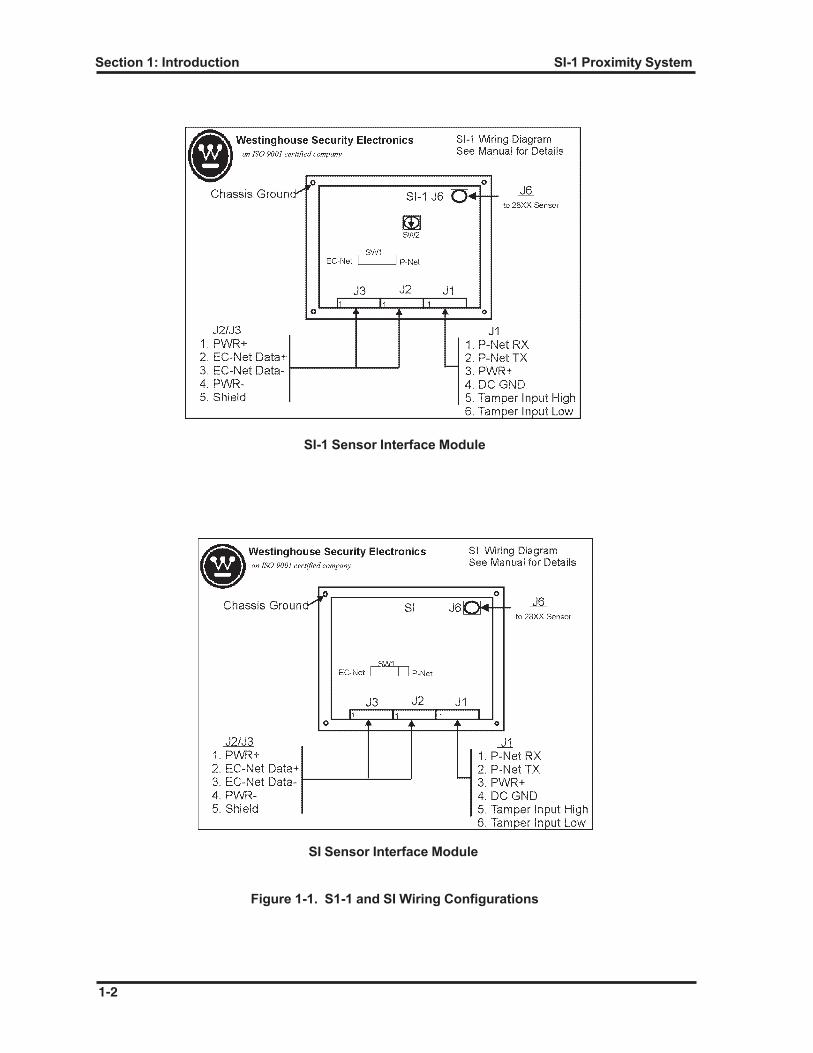
The SE 422 ACU may have either of two Sensor Interface Modules, an SI-1 and an SI. These are
not interchangeable. If you attempt to replace an SI-1 with an SI without making the necessary
corrections, you will destroy the SI-1 PCB. Refer to Figure 1-1 for wiring information.
Scope
This manual describes the hardware installation, wiring, database setup, and maintenance
procedures necessary for operation of the SI-1 Sensor Interface and SE 2814A and SE 2815A
Proximity Sensors with the SE 422 ACU (Figure 1-2). This manual also assumes that the SE 422
is installed. Note that the manuals included with the SE 422 cover overall system operation and
the installation of the VIP2 (Verified Identification of Personnel) keypads and magnetic stripe
readers.
Section 1: Introduction
1-2
SI-1 Proximity System
SI-1 Sensor Interface Module
Figure 1-1. S1-1 and SI Wiring Configurations
SI Sensor Interface Module

1-3
Secti
on
1:
Intr
od
ucti
on
SI-
1 P
roxi
mit
y S
yste
m
Fig
ure
1-2
. S
E 4
22 S
yste
m W
irin
g D
iag
ram
EARTH GROUNDSHIELDPWR +PWR -DATA -DATA +EARTH GROUNDSHIELDPWR +PWR -DATA -DATA +EARTH GROUNDSHIELDPWR +PWR -DATA -DATA +
DATA ADATA BPWR -PWR +
EARTH GROUNDDATA ADATA BPWR -PWR +
EARTH GROUND
PWR +EARTH GROUND
DATA ADATA B
PWR -
SHIELDPWR -DATA -DATA +PWR +
TAMPER INPUTTAMPER INPUT
P111 1 1P10 P9
1
1
1
P8
P7
P6
F1
F2
F3
F4 F5 F6 F7
P3
1
1
P2
J3
1
1
J2
J1
1
V I P 2
M A G N E T I C S T R I P ER E A D E R
S I - 1
S E 4 2 2
RED
BRNWHTGRN
BLK
PWR +DATA +DATA -PWR -SHIELD
RXTX
PWR +DC GND
SW2SW1
J6
2 8 1 4 O R 2 8S E N S O R U P
WIRE NUT
- +B A T T E R YB A T T E R Y
+-
ADDRESSSWITCH
D S
DOOR 1
R E X
L K
L S 1 - B
L S 1 - A
R E X 1 - A
R E X 1 - B
D O O R 1L O C K R E L A Y
D O O R 2L O C K R E L A Y
D O O R S T R I K ED O O R 1D O O R 2
L P
+-
L O C KP O W E R
P8/PWR +P8/DATA +P8/DATA -P8/PWR -P8/SHIELD
P8/DATA +P8/DATA -P8/PWR +P8/PWR -P8/SHIELD
P8/PWR +
P8/SHIELDP8/DATA +
P8/DATA -P8/PWR -
P1 P2
P4
M O D E M
P C O R T E R M I N A L( O P T I O N A L )
MODEM(OPTIONAL)
P5
N O D E S 1 5 - 1 6U P T O 2 e a .
N O D E S 1 3 - 1 4U P T O 2 e a .
TERMINATION RESISTOR120 OHM 1/2 WATT
AC POWER
120/220 PI2ea. MAY BE REQUIREDFOR MORE THAN 5 NODES.
24V OR 2ea. 12V
M O V
P 1 - 1 N / CP 1 - 2 N / CP 1 - 3 T I PP 1 - 4 R I N GP 1 - 5 N / CP 1 - 6 N / C
1 D A T A C A R R I E R D E T E C T2 R E C E I V E D D A T A3 T R A N S M I T D A T A4 D A T A T E R M I N A L R E A D Y5 S I G N A L G R O U N D6 D A T A S E T R E A D Y7 R E Q U E S T T O S E N D8 C L E A R T O S E N D9 R I N G I N D I C A T O R
P 2 & P 4
SW1 MUST BE SET TO "EC-NET"

Section 1: Introduction
1-4
SI-1 Proximity System

SECTION 2: MOUNTING
2-1
INTRODUCTION
Use the following section to mount the SI-1 Sensor Interface Module and its components.
MOUNTING THE ENCLOSURE
Remove the enclosure (metal box) from its shipping container and plan its installation. Do not
install the SI-1 at this point. Plan that the location for the enclosure be in a secure but accessible
place. It should be protected from the weather (refer to Appendix A for more details). It should
be as close as practical to the SE 28XX sensor in order to keep the coax cable as short as
possible—no more than 250 ft (76 m) maximum.
Normally, the hinge on the enclosure door is on the left and wires enter the enclosure through the
knockouts in the top or on either side (Figure 2-1). If conduit is already in place so that wires must
enter from the bottom, you should turn the enclosure over so the hinge is on the right. Avoid using
what would normally be the bottom knockout (the knockout closest to the ground screw hole in the
enclosure); clearance is minimal between it and connectors on the PCB.
Figure 2-1. Enclosure for the SI-1

2-2
Section 2: Mounting Components SI-1
Remove the knockout (s) from the enclosure for the coax cable to the SE 28XX sensor, for device
network data and power cable (s) to the SE 422 and to any other device that will be connected to
the SI-1.
Screw or bolt the enclosure in place and connect the conduit to it. If there is no conduit connected
to the enclosure or the conduit system will not provide an adequate earth ground connection, run
a bare or green ground wire to the enclosure from the building or from the computer system�s
grounding electrode. Note that the enclosure must be securely earth grounded. Use strain relief
cable clamps in knockouts if conduit is not used.
Install the No. 6 grounding screw (included in the bag of hardware) through the hole provided in
the enclosure. Tighten one of the supplied nuts on the inside of the screw so that the captive
washer bites through the paint on the enclosure.
Install the tamper switch on the enclosure according to the instructions in the bag with the switch.
MOUNTING THE SI-1
Caution
Components on a PCB (Printed Circuit Board) may be destroyed by inadvertent discharge of static
electricity. To reduce the potential of electrostatic discharge, each PCB is shipped in a protective
bag. Leave the PCB in the protective bag until you are ready to install it. Before removing a PCB
from its bag, touch a grounded object to discharge any static electricity that may have accumulated
on you or your clothing. If possible, ground yourself with a wrist-strap clip lead while installing the
PCB. To minimize static electricity, keep away from vinyl or other plastic and move as little as
possible while on carpets. Handle the PCB by it edges only. Do not touch exposed circuity or
connector pins, and do not rest the board on a metal surface.
1. Remove the PCB from its bag.
2. Connect the free end of the grounding jumper that is attached to the mounting plate on the
sensor interface module to the grounding screw. Also connect the bare or green-grounding
wire (if any) to the grounding screw and screw on, but do not tighten the other supplied nut.
3. Line up the holes in the SI-1 mounting plate with the standoffs in the enclosure and snap the
SI-1 in place in the enclosure.
5. Insert the crimped leads from the tamper switch into positions 5 and 6 of the 6-pin Phoenix
connector and tighten, ensuring that the leads are secure. Refer to Figure 2-2 for information
about using Phoenix connectors.
6. Plug the Phoenix connector into connector J1 on the SI-1 PCB.

2-3
Section 2: Mounting ComponentsSI-1
Figure 2-2. Typical Phoenix Connector
MOUNTING THE SE 28XX SENSORS
Use the following information to mount the SE 28XX sensors.
1. Remove the SE 28XX sensor form the packaging and inspect it for any defects.
2. Install the sensor as close as possible to the door handle on the entry where people can easily
use it, about the same height as the door handle (Figure 2-3).
3. Install the sensor on, in, or behind any nonconductive material. Note that in low-risk
installations, surface mounting is permissible. However, for greater security, install the
sensor in or behind a wall (Figure 2-4).
n If a sensor is installed behind something, the distance between its face and the outside
surface should be less than about an inch (2.5 cm). Sensors work best when command keys
are presented within 3 in (7.6 cm) of them.
n A sensor cannot read command keys through conductive materials like metal siding,
insulation foil, expanded metal lath, safety wire mesh within glass or even some types of
metallic coatings on glass. Any conductive material (foil, metal mesh stucco lath, concrete
reinforcing steel, power wiring, metal door jambs and casing, metal siding, structural beams)
closer than about 4 in (10.2 cm) to a sensor edge will reduce the read range.

2-4
Section 2: Mounting Components SI-1
Figure 2-3. Example of a Sensor Installation
Figure 2-4. Sensor Mounted in Side a Wall

2-5
Section 2: Mounting ComponentsSI-1
n If conductive material is along one edge only, operation will usually be satisfactory if the
sensor edge is at least 1 in (2.5 cm) from it. If conductive material is on all sides, maintain
at least 3 in (7.6 cm) all around. If the wall surface is conductive, you can either cut a hole
in it at least 14 x 14 in (35.5 cm x 35.5 cm) and center the sensor on a nonconductive area,
or mount the sensor at least 1.5 in (3.8 cm) in front of it with a standoff such as the SE 2700
(Figure 2.5).
Figure 2-5. Sensor Mounted on a Standoff
n If the sensor will be hidden, mark the location of its center with a decal so keyholders will know
where to present their command keys. Also, provide a removable access panel on the secure
side of the wall for installation and service.
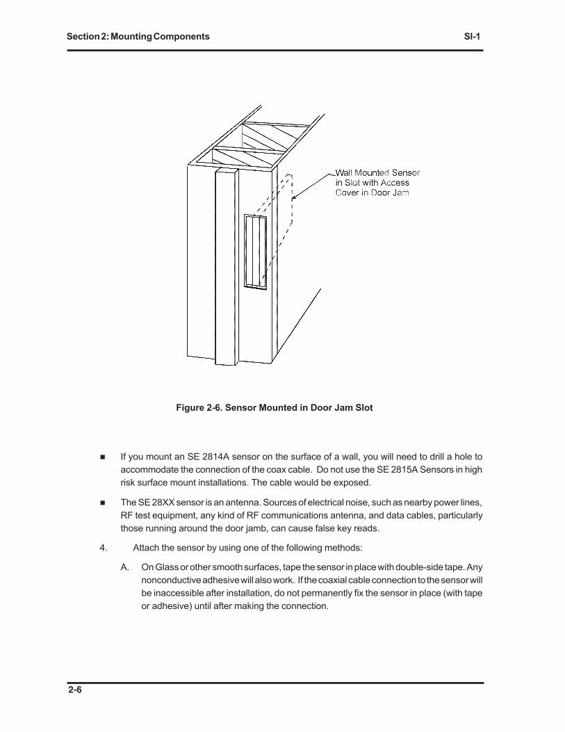
n If neither side of the wall is secure, you may be able to install the unit in a slot in the wall and
provide access to it through a removable section of the door jam (Figure 2-6).
n The SE 28XX sensors can tolerate temperatures between -46oC (-50oF) and 82oC (180oF)
and are weather resistant. Sensors absorb solar radiation because of their dark color, and
in strong, direct sunlight, they can overheat and cause a temporary malfunction or permanent
damage. Shade them from the hottest afternoon sun.
n If the installation will be subject to the weather where moisture could collect on the cable and
run down to the connector, plan to orient the sensor so the connector will be on the side or
bottom, rather than the top. Also, plan to route the cable so you can provide a drip loop in
the cable that is lower than the connection point.
2-6
Section 2: Mounting Components SI-1
Figure 2-6. Sensor Mounted in Door Jam Slot
n If you mount an SE 2814A sensor on the surface of a wall, you will need to drill a hole to
accommodate the connection of the coax cable. Do not use the SE 2815A Sensors in high
risk surface mount installations. The cable would be exposed.
n The SE 28XX sensor is an antenna. Sources of electrical noise, such as nearby power lines,
RF test equipment, any kind of RF communications antenna, and data cables, particularly
those running around the door jamb, can cause false key reads.
4. Attach the sensor by using one of the following methods:
A. On Glass or other smooth surfaces, tape the sensor in place with double-side tape. Any
nonconductive adhesive will also work. If the coaxial cable connection to the sensor will
be inaccessible after installation, do not permanently fix the sensor in place (with tape
or adhesive) until after making the connection.

2-7
Section 2: Mounting ComponentsSI-1
B. On rough surfaces or where additional security is necessary, use bolts. Carefully drill
through the four corners at the locations marked on the sensor with a drill no larger than
#8 (0.199�). Then, using the template supplied with the sensor, drill the surface behind
it (four holes in a square, a sensor into misplaced holes will break the sensor housing).
If possible, drill through the wall and use standard #10 (3/16�) roundhead or panhead
bolts and nuts. Do not attempt to countersink flathead bolts in the plastic sensor
housing. Stake the nuts, or use jamb nuts so no one will be able to remove the bolts
from the outside. Drill for masonry anchors in thick masonry. In exposed and high risk
areas, you may want ot use special screws providng more security against potential
tampering.

2-8
Section 2: Mounting Components SI-1

SECTION 3: WIRING
3-1
INTRODUCTION
Connections and wiring procedures for the SI-1 are as follows:
Routing Coaxial Cables
Route the coax cable, SE 9284 (SE 9284-DB for wet or all-weather environments), between the
SI-1 and the SE 28XX sensor before installing connectors on the ends. Keep the run as short as
possible; 6 to 10 feet (2 to 3 m) will be enough in may cases; 250 ft (76 m) is the limit.
Keep the cable away from conductors carrying power line voltages, high current, audio signals for
paging speakers, or RF in the 1 to 30 MHz range. Shielded power, data, monitor, lock, and relay
wiring from the SE 422 or the SI-1 in the same conduit will not normally cause problems. Avoid
cable splices, bends sharper than 2� (5 cm) diameter, and anything which pinches or distorts the
cable.
Do not use metal cable clamps or ties. If you must splice the coax (one splice per cable maximum),
use F81C type cable connectors only. Cover the splice connectors with heat-shrink tubing or
electricians�s tape.
Inserting Coax Cable Connectors (Figure 3-1)
1. Slip the large metallic-colored outer clamp ring over the cable.
2. Strip off about 3/4� (1.9 cm) of the outer insulation jacket. (Do not damage braid under it.)
3. Fold the braid back over the outer insulation jacket.
4. Strip off about 5/8� (1.58 cm) of the inner insulation (do not nick the center conductor).
5. Push the connector under the braid as far as possible and trim off the folded-back braid.
6. Slide the outer ring up and crimp it in place using a hex crimp tool. Note that the middle jaw
(0.324�) is best for this purpose.
7. Clip the inner conductor off so it extends about 1/16� (1.588 mm) beyond the end of the
connector.
8. Connect the SI-1 end of the coax to the angle connectors.
9. Screw angle connector to J6 on the SI-1 PCB.
10. Connect the other end of the coax to connector on the sensor.
11. Tighten with a 7/16 open-end wrench (use silicon grease to lubricate and seal joint).

Section 3: Wiring
3-2
SI-1
Figure 3-1. Installing Coax Cable Connectors

3-3
Section 3: WiringSI-1
Data and Power Network Wiring
If the SE 422 is not installed, install it now; refer to its installation and operation manual, P/N
66107567001. The following steps refer to connections at the SI-1 Sensor Interface module.
Pull the device data and power cable from the SE 422 to the SI-1. Westinghouse Security
Electronics recommends four-conductor, 18 gauge shielded cable (Figure 3-2) such as Alpha
5164 or Manhattan M5394 for general purpose data and power wiring, and 1000 ft (305 m) as the
maximum network length from end to end.
n If your system consists of an SE 422 and a single SI-1, the SE 422 will be located on one end
of the network and the SI-1 will be on the other end.
n If your system includes another SI-1, or one or more VIP2 keypads or magnetic strip readers,
they will be daisy chained on the same network.
n If the system consists of one SI-1 and one or more other devices (VIP2 and/or MSR), pull a
cable from the SE 422 to the SI-1 and connect the other devices on a separate cable from
the SE 422.
n If the system includes two SI-1s, run separate cables from the SE 422 to each SI-1.
n If the system includes two SI-1s and one other device, run one cable from the SE 422 to each
SI-1. You can then continue on from one SI-1 to the other device, or run through the other
device on the way to the SI-1. In general, keep wiring as short as possible to the SI-1.
n If the system includes two SI-1s and two other devices, place one of the other devices on each
cable run from the SE 422.
n Any cable, either to the SE 422 or to another device, must be long enough in the SI-1
enclosure to loop near the grounding screw on the way to connectors J2 and/or J3.
Connectors J2 and J3 on the SI-1 PCB, and P7 and P8 on the SE 422 PCB are equivalent
and interchangeable. You can use either connector for one cable or both connectors for two
cables.
Connecting Cable Shield to the Enclosure
Note
If you do not have enough cable to pass the ground screw on the way to J2 or J3, you can drill a
hole in the enclosure and install a second ground screw near the knockout where the cable enters.
Remove the SI-1 PCB first to avoid possible damage to it and to prevent metal chips from falling
on it.

Section 3: Wiring
3-4
SI-1
Figure 3-2. Connecting Shield to the Enclosure
1. Strip the cable outer insulating jacket (not shield braid) back to the ground screw.
2. Slip the orange outer shield-kon sleeve over the cable and push it back onto the cable jacket.
3. Push the shield braid back to form a fat ring about half an inch from the end of the insulating
jacket.
4. Trim the ring carefully and remove excess braid (braid should extend a half inch).
5. Loosen the braid (if necessary) and slip the green inner shield-kon sleeve under it.
6. Lay the stripped (and tinned) end of one of the ground pigtails on the exposed braid.
7. Position the orange sleeve over the braid and pigtail end, and crimp the sleeve in place.
8. Trim the braid for a neat installation. The inner sleeve protects the wires from being crushed,
so the sleeve assembly should remain loose, attached to the braid only, not the wires inside
cable. The final assembly should be as shown in Figure 3-3. Note that you can install the
pigtail coming out of the back of the sleeve if it will make reaching the ground screw easier.
9. In an emergency (if the shield-kon sleeves are not available), strip the cable outer jacket.
10. Loosen the braid (by shoving it back) enough to spread a hole in it.
11. Bend the cable in order to pull a loop of the conductors through.
12. Cut the braid to the right length (no more than 2� (6.35 cm) to reach a ground stud or screw.
13. Crimp a ring lug on the end of the braid.

3-5
Section 3: WiringSI-1
Figure 3-3. Shield-kon Sleeve Installation
14. Remove the foil covering and the loose strings from the conductors. Do not cut the shield-
drain lead.
15. Place the ring lug (on the pigtail or the end of the braid) over the ground screw on the SI-1
enclosure along with the grounding jumper and the bare or green enclosure grounding wire
(if any).
16. Tighten the nut on the screw.
17. If the cable is not in conduit, tighten the strain relief cable clamp just enough to hold the cable
in place; do not overtighten.

Section 3: Wiring
3-6
SI-1
Installing the Conductors in J2 and/or J3
Caution
To avoid RF radiation and to meet FCC requirements, all wiring from the SE 422 must be shielded
or in metal conduit. If you are adding SI-1/SE 28XX proximity capacity to an existing SE 422 system
that does not use shielded cable, you must replace all non-shielded wiring with shielded cable. Use
the procedure outlined above on all cables in the SE 422 enclosure. Use the grounding stud in the
SE 422 enclosure instead of the grounding screw described for the SI-1. Similar shield connection
techniques must also be used in VIP2 Keypads. At magnetic strip readers, connect both the shield
and the shield drain to the brown lead.
Connect the shield drain lead to earth ground (pin 5, J2 or J3 on the SI-1 PCB).
Westinghouse recommends the following procedure. (This avoids tinning wire ends with solder
in the field, which would otherwise be required for UL certification, and provides a much more
secure and reliable installation.)
1. Strip the wire ends at least 3/8� (9 mm); use the length of the bare metal on the crimp sleeves,
as a guide. A stripping tool such as the Weidmuller Stripax (cat. #90050.0) or Mini Stripax
(cat. #90012.8) is recommended for stripping insulation accurately without cutting wire
strands.
2. Twist the exposed strands tightly and crimp a sleeve (such as Weidmuller H 0.5 through H
4.0 series insulated crimp sleeves on the ends of the wires with a tool such as Weidmuller
PZ4 (cat. #90125.0). Be sure the sleeves are crimped on bare conductor metal, not the
insulation. Use yellow sleeves on single 18-gauge wires and blue sleeves when two 18 gauge
wires will go in a single position (Figure 3-4).
3. Put the crimp sleeve in place in the connector (Table 3-1).
4. Tighten the binding screw, wiggle and gently pull on the wires, and tighten the screw again.
5. On the SI-1 PCB, set the slide switch SW1 to the EC-NET position.
6. Set hex switch SW2 to represent the SI-1 serial number (0 to 15 corresponding to 0 to F on
the switch. Each SI-1 must have a different setting when connected to an SE 422.
7. Connect the other end of the device network cables similarly at the SE 422 (Table 3-1).
8. Terminate both ends of the data network with a 120 ohm resistor. If the SE 422 or and SI-
1, VIP2 Keypad, or a Magnetic Stripe Reader has only one device network cable running to
it, connect a 120-ohm resistor between DATA A(+) and DATA B(-). Use the empty network
connector on an SI-1 or VIP2. Do not connect the resistor where two device network cables
connect.

3-7
Section 3: WiringSI-1
Figure 3-4. Typical Wiring Termination
Table 3-1. SE 422 Device Network Pinout
P7/8 Functions Color Code
1 DATA A (+) White
2 DATA B (-) Green
3 PWR (-) Black
4 PWR (+) Red
5 Shield
6 Earth Ground Shield Drain

Section 3: Wiring
3-8
SI-1
Power Inserter Wiring
The SE 422 system with the proximity option is FCC certified only when powered by an SE Power
Inserter (PI). Westinghouse Security Electronics recommends that you use a PI power supply.
Install and connect the PI to the SE 422 as follows (Table 3-2):
1. Arrange for a dedicated AC circuit with a reliable connection at the receptacle to the building
(or computer system) grounding electrode.
2. Install the PI in a secure area protected from weather and temperature extremes. Be sure
that air can circulate around it freely and that the PI power cord is long enough to reach the
receptacle—never use extension cords.
3. Pull shielded cable between the PI and the SE 422.
n You will need two conductors for PWR+ and PWR-. You will need two more if the PI will be
providing lock power and another two if the PI power fail monitor will be connected to the SE
422. The power fail monitor, like the tamper switches, requires setup with a terminal. It is
useful only if standby batteries are connected.
4. Connect shields at the SE 422 as described above. Connect shields at the PI to one of the
cover screws on either side of the output connectors. The drain wire may be connected to
the cover screw or cut off.
Table 3-2. PI to SE 422 Pinout
PI Connector/Pin SE 422 Connector/Pin
J1/2-1 PWR+ P11-1 -Power In A
J1/2-2 (not connected)
J1-2-3 (not connected)
J1/2-4 PWR- P11-3 DC Power Return
J3-1 PWR Fail+ P11-4 PWR Monitor Input
J3-3 Lock Power+ P9-2 or 5, Lock Common
J3-4 Lock Power- (from the lock or locks)
J3-5 BATT+ (to + on the batteries)
J3-6 BATT- (to - on the batteries)

SECTION 4: SE 422 SETUP
4-1
INTRODUCTION
At start-up, a new SE 422 reads the serial numbers of devices connected to plugs P7 and P8 on
the SE 422 PCB. The serial numbers are stored permanently in a data base, even if power fails.
Any changes made in those original devices, adding or removing a device, or replacing one device
with another of the same or different type, and the SE 422 database must be reset. This setup
procedure can be performed from the SE 422 front panel or from a terminal keyboard connected
to the system.
Database Setup from the Front Panel
To setup the SE 422 database from the front panel proceed as follows:
1. To read the serial numbers, first set the configuration DIP switches of SW2 on the SE 422
PCB so the SE 422 can recognize the new devices that you intend to connect. Note that
depressing the lower end of the rocker (closest to the heat sink and memory backup battery)
sets the switch to off. Switches 1, 2, and 3 select the devices for Entry 1. Switches 4, 5, and
6 select the devices for entry 2 (Table 4-1).
Note
Always leave DIP switch 7 off and switch 8 on. Switches 7 and 8 connect the memory backup
battery in order to protect the system database in case of a power failure.
Table 4-1. Configuration Switch SW2 Settings
Entry 1 Entry 2
Switch Setting Switch Setting
1 2 3 4 5 6
off off off No Reader Attached off off off
on off off MSR Only on off off
off on off SE 28XX Only off on off
on on off MSR & SE 28XX on on off
off off on VIP2 Keypad Only off off on
on off on MSR & VIP2 Keypad on off on
off on on VIP2 & SE 28XX off on on
on on on MSR, VIP2 & SE 28XX on on on

Section 4: SE 422 Setup
4-2
SI-1
2. When the switches are set to match the devices (s) that you intend to connect, log on at the
SE 422 front panel and enter the 9901 command. This instructs the SE 422 to read the
switches. (Refer to the SE 422s operations manual for log in instructions.)
3. Shut off power and unplug connectors P7 and P8 on the SE 422 PCB. Apply power and wait
60 seconds for the SE 422 to record everything as off line.
4. Remove the serial numbers of the old devices from the SE 422 memory.
a. To remove the VIP2 Keypad serial numbers, log on at the front panel and enter
commands 811 and 812.
b. To remove the MSR serial number, enter commands 821 and 822.
c. To remove SI-1 serial numbers, enter 831 and 832 at Entry 1 and Entry 2, respectively.
5. Shut off power.
6. Disconnect the old devices from the network.
a. If you are adding two new devices, connect the device at Entry 1 first.
b. Plug in P7 and P8 and apply power. The SE 422 will take several minutes to read the
serial number. The LED on SI-1 board and the S-NET RX STATUS LED on the SE 422
board will start flashing normally when communications are established. If you have a
device at Entry 2, shut off power, connect the device there, and apply power.
Database Setup from the Terminal
To setup the SE 422 database using a terminal, proceed as follows:
1. Log on, and use the ENTRY command for Entry 1.
2. Assign VIP2 Keypad at Entry 1 to address 13, assign an SI/SE 28XX at Entry 1 to address
15, and assign an MSR at Entry 1 to address 17.
3. Repeat the process for Entry 2, that is, assign a VIP2 at Entry 2 to address 14, assign an SI/
SE 28XX at Entry 2 to address 16, and assign an MSR at Entry 2 to address 18.
4. Shut off power.
5. Disconnect P7 and P8, and change the devices. Leave P7 and P8 unplugged for the next
step.
6. Apply power to the SE 422, log in, and use the SERIAL command to set the serial number
of any device you are replacing to 0 (type 0 and press Enter), or if you know the serial number
(s) of the devices (s) you have connected, enter them.

4-3
Section 4: SE 422 SetupSI-1
7. Shut off power, plug in P7 and P8, and apply power. If you have entered the serial numbers
correctly, the SE 422 should communicate with the devices immediately. If the SE 422 has
to read the serial numbers, the process will take several minutes.
8. If you are letting the SE 422 read the serial numbers of the same type of device at each entry,
and want to make sure that the device at Entry 1 is assigned to the address reserved for Entry
1, connect it first. Then shut off power, connect the device at Entry 2, and apply power.
Note
Refer to the SE 422 manuals for additional information about the database setup procedure.
ENTERING THE SE 1050 COMMAND KEYS
Adding to or removing command keys from the SE 422 database is similar to adding or removing
magnetic stripe cards as described in the SE 422 ACU manuals. Note that each command key
has its eight-digit number imprinted on the key.
You can load command keys using the following methods:
A. You can load the keys individually at the front panel by entering command 32 followed by
entering the eight-digit key number for privileged keys or command 33 for nonprivileged keys.
B. You can also add nonpriviledged keyholders by entering command 841 (Entry 1) or 842
(Entry 2) and presenting the keys individually to the SE 28XX Sensors.
C. You can add keys by entering the Group Command (GR), followed by presenting the keys
to a sensor.
B. You can add keys by entering the key command. Then enter the key codes of the key at the
terminal keyboard.
Removing command keys requires that you enter the command 42 followed by entering the
eight-digit key number for privileged keys and command 43 followed by the eight-digit key
number for nonprivileged keys at the front panel.
Once you have finished entering key codes, check to see that they work. When you present a
command key at an entry that has an SE 28XX Sensor only, the SE 422 should grant access and
unlock the entry for about 10 seconds, or until you open it. The lock will then relock. If you open
the entry, it will be locked when it closes. Make sure the entry switch wiring is correct. The SE
422 will not let sensors read keys when it senses the entry is open.
If an SE 28XX sensor and an MSR are at an entry point, someone wishing to enter can use either
their magnetic strip card or their command key. In either instance, the light on the MSR will indicate
access granted by changing from red to green for 10 seconds or will indicate access denied by
going out for 10 seconds.

Section 4: SE 422 Setup
4-4
SI-1
If an SE 28XX Sensor is used with a VIP2 Keypad, operation is similar to that of an MSR with a
VIP2 Keypad. The top and middle lights on the keypad will normally be on, indicating that you will
need to present your command key and enter your PIN number, one after the other.
Note
The order in presenting your command key and PIN number doesn�t matter, but the SE 422 does
impose a time limits. You have 10 seconds to enter you PIN after you present your command key.
If you take too long or enter a PIN that the SE 422 does not recognize, you will have to wait about
10 seconds before you can try again.
When the SE 422 recognizes your PIN, the middle light will go out. When the SE 422 recognizes
your key, the top light will go out. Then the bottom light comes on, indicating that the SE 422
granted access and that the entry is unlocked.
INSTALLATION CHECKLIST
o Open the box containing the SE 422 proximity reader hardware.
o Identify all components and verify that no components are damaged.
o Install the SI-1.
o Install the SE 28XX.
o Pull coaxial angle cable between the SI-1 and SE 28XX.
o Terminate and connect the cable.
o Pull the device network data and power cable between the SI-1 and the SE 422, and any other
devices that may be on the network.
o Connect shields at both ends of the cable (s). Connect the wires (see Figure 1-1).
o If the system power supply is not an SE Power Inserter (PI), replace it with a PI.
o Perform the SE 422 setup procedure.
o Group Load one or more SE 1050 Command Keys into the SE 422 and verify that the SE
28XX reads them at each door.
DIAGNOSTIC CHECKS
If the SE 422 does not function properly, check for the following problems:
o The command key is the wrong type (that is, SE 1030 or SE 1040).
o The SE 422 does not recognize the key code (key not in memory).
o The building is armed and the key is not privileged (wrong access code).

4-5
Section 4: SE 422 SetupSI-1
o Incorrect SW2 setting for the devices connected, or incorrect serial numbers for those
devices recorded in the SE 422 database. Be sure to follow the setup procedures carefully,
and check the LED on the SI-1 for indication of being powered up and online. The indicator
on each MSR should normally be red. The middle, or middle and top LED on VIP2 keypads
should be on.
o Inadequate voltage at the SI-1: Pins 1 and 4 of connectors J2 or J3 on the SI-1 should have
at least 17 Vdc between them at all times. You may need to monitor the voltage over time
to catch short term fluctuations. The sensor and the SI-1 have LEDs that will be dim or out
if the supply voltage is low. The possible causes of low supply voltage include the following:
o Low AC line voltage.
o Operation from partially discharged standby batteries.
o Defective PI or other power supply.
o Bad connections.
o Wires too small for the current and distance between the SE 422 (or PI) and the SI-1.
o System grounding: SI-1s and SE 422s must be reliably earth grounded for safety, and for
transient and lighting protection.
o Reliable communications on an EIA-485 network also requires that signal ground voltage at
an SI-1 and at the SE 422 be fairly close. Problems can arise if the SI-1 and SE 422 are earth
grounded to different grounding electrodes in different and distant buildings.
o Conduit joints loosen, separated or corroded, or power wiring defects energize parts of the
conduit system.
o The DC common wire between and SI-1 and SE 422 is so long or small that return current
in it produces too much voltage drop from end to end.
o A simple test for signal-ground offset in an operating system is to measure the AC and DC
voltage between pin 3 (PWR-) of P7 or P8 and pin 6 (GND) of P7 or P8. Using a VOM, This
voltage offset must never be more than 2 volts.
o Noise: Data wiring is vulnerable to crosstalk between adjacent wires and pickup of electrical
noise. Either can cause unreliable operation. Even wiring that meets ordinary standards for
good practice can pick up spurious signals from obscure sources. Generally, the symptoms
will point to a particular part of the system. If only on SE 28XX sensor consistently
malfunctions, check that the sensor or the coax cable to its sensor interface module. If two
sensors connected to the SE 422 fail, check the SE 422 or the wiring between it and the SI-
1.
o Intermittent or random communication problems, however, may be much more difficult to
track down. First check to see that the wiring meets the guidelines outlined in this manual,
then isolate the problem. If you suspect it may be crosstalk between the wires in a particular

Section 4: SE 422 Setup
4-6
SI-1
conduit run, connect a temporary by pass for the suspected circuit outside the conduit. If you
suspect a wire is picking up fields generated by nearby equipment, try rerouting or shielding
it. Be sure all shields and conduit are grounded properly.
Note
If you suspect outside signals are being picked up by the sensor itself and interfering with valid key
reads, contact with WSE Customer Service for additional guidance.
LED Diagnostic Checks
The SE 28XX Sensor has one LED in the middle of the PCB. When the sensor is used with the
SI-1, the sensors LED should not be blinking, but it should be on steady. If the LED is out, voltage
at the sensor is probably inadequate for operation. Check the power input to the SI-1 sensor
interface.
The SI-1 has one (normally blinking) LED in the middle of the PCB. If it is out, voltage to the PCB
is probably inadequate. However, the SI-1 LED indicates much more than power to the board.
Table 4-2 lists some of the meanings of the blinking SI-1 LED. Because of interrupts coming from
the SE 422, the LED blinks are not always entirely regular; watch through several cycles before
drawing any conclusions.
Table 4-2. SI-1 LED Troubleshooting
LED State Indication
One blink followed by
two blinks.
The SI-1 is communicating normally with both sensors and
the SE 422. No key is being presented or read.
Two Blinks. The SE 422 is functioning, but the SI-1 has a problem
reading its sensor.
One blink followed by
two blinks followed by
three blinks.
The SI-1 is communicating with the SE 422 and is sensing
the presence of a key and is attempting to read that key.
On steady. The SI-1 microprocessor is functioning, but the SI-1 is not
communicating with the SE 422. Either the SI-1 is not
connected, it is not responding, or the wiring is faulty.
Failure to configure the SE 422 to recognize an SI-1/SE28XX is another possiblility. The SI-1 will not try to
communicate with its sensor unless the SE 422 recognizes
it. (See Table 4-l for setting the configuration dip switches,
SW2.)

APPENDIX: SPECIFICATIONS
A-1
INTRODUCTION
This appendix provides certain hardware specifications and wire size and type information.
HARDWARE SPECIFICATIONS
Refer to the following table for a list of hardware specifications:
WIRE SIZES AND TYPES
The following provides cable and wiring requirements that will satisfy normal safety standards, and
local codes must be followed:
n No power wires can be smaller than 18 gauge.
n Ends of wires clamped under binding screws or similar parts must be tinned or terminated
with crimp devices.
n Wire splices must be insulated to withstand the same voltage and other conditions that the
wires are required to withstand.
n Flexible power lines of any type must be protected with bushing when they pass through walls
and sheet metal.
n All components are connected with twisted pair wire plus shield except the sensor interface
(SI-1) which is connected by coax cable to the sensor, and the teleco line is used for
connecting the internal modem in the ACU.
n Ground all components (earth ground) through a metallic conduit system connected at one
point to the building grounding electrode or through a separate grounding wire.
Hardware Specifications
Key/Reader Technology 1050 Type Proximity Cards
Communication Interface S-Net (RS485)
Tamper Input 4-State
Operating Voltage 17 to 28 Vdc
Operating Current at 18 Vdc 150 Milliamps Maximum
Operating Temperature 20o to 120oF
Operating Humidity 0 to 90% Noncondensing

Appendix: Specifications
A-2
SI-1