sdm tables short description - casa.nrao.edu filesdm tables short description...
TRANSCRIPT
SDM Tables Short Description
COMP-70.75.00.00-00?-A-DSN
March 19, 2018
Design Document
F.Viallefond, R. Lucas
SDM Tables Short Description
Doc#: COMP-70.75.00.00-00?-A-DSNDate: March 19, 2018Status: DraftPage 2
Contents
1 List of ASDM Tables 61.1 Versioning information for the ASDM. . . . . . . . . . . . . . . . . . . . . . . . . . . . . . . 71.2 Main Table . . . . . . . . . . . . . . . . . . . . . . . . . . . . . . . . . . . . . . . . . . . . . . 81.3 AlmaRadiometer Table . . . . . . . . . . . . . . . . . . . . . . . . . . . . . . . . . . . . . . . 101.4 Annotation Table . . . . . . . . . . . . . . . . . . . . . . . . . . . . . . . . . . . . . . . . . . 111.5 Antenna Table . . . . . . . . . . . . . . . . . . . . . . . . . . . . . . . . . . . . . . . . . . . . 131.6 CalAmpli Table . . . . . . . . . . . . . . . . . . . . . . . . . . . . . . . . . . . . . . . . . . . 151.7 CalAntennaSolutions Table . . . . . . . . . . . . . . . . . . . . . . . . . . . . . . . . . . . . . 171.8 CalAppPhase Table . . . . . . . . . . . . . . . . . . . . . . . . . . . . . . . . . . . . . . . . . 191.9 CalAtmosphere Table . . . . . . . . . . . . . . . . . . . . . . . . . . . . . . . . . . . . . . . . 231.10 CalBandpass Table . . . . . . . . . . . . . . . . . . . . . . . . . . . . . . . . . . . . . . . . . 261.11 CalCurve Table . . . . . . . . . . . . . . . . . . . . . . . . . . . . . . . . . . . . . . . . . . . 291.12 CalData Table . . . . . . . . . . . . . . . . . . . . . . . . . . . . . . . . . . . . . . . . . . . . 311.13 CalDelay Table . . . . . . . . . . . . . . . . . . . . . . . . . . . . . . . . . . . . . . . . . . . 331.14 CalDevice Table . . . . . . . . . . . . . . . . . . . . . . . . . . . . . . . . . . . . . . . . . . . 351.15 CalFlux Table . . . . . . . . . . . . . . . . . . . . . . . . . . . . . . . . . . . . . . . . . . . . 371.16 CalFocus Table . . . . . . . . . . . . . . . . . . . . . . . . . . . . . . . . . . . . . . . . . . . 391.17 CalFocusModel Table . . . . . . . . . . . . . . . . . . . . . . . . . . . . . . . . . . . . . . . . 421.18 CalGain Table . . . . . . . . . . . . . . . . . . . . . . . . . . . . . . . . . . . . . . . . . . . . 441.19 CalHolography Table . . . . . . . . . . . . . . . . . . . . . . . . . . . . . . . . . . . . . . . . 451.20 CalPhase Table . . . . . . . . . . . . . . . . . . . . . . . . . . . . . . . . . . . . . . . . . . . 481.21 CalPointing Table . . . . . . . . . . . . . . . . . . . . . . . . . . . . . . . . . . . . . . . . . . 511.22 CalPointingModel Table . . . . . . . . . . . . . . . . . . . . . . . . . . . . . . . . . . . . . . 541.23 CalPosition Table . . . . . . . . . . . . . . . . . . . . . . . . . . . . . . . . . . . . . . . . . . 561.24 CalPrimaryBeam Table . . . . . . . . . . . . . . . . . . . . . . . . . . . . . . . . . . . . . . . 581.25 CalReduction Table . . . . . . . . . . . . . . . . . . . . . . . . . . . . . . . . . . . . . . . . . 601.26 CalSeeing Table . . . . . . . . . . . . . . . . . . . . . . . . . . . . . . . . . . . . . . . . . . . 621.27 CalWVR Table . . . . . . . . . . . . . . . . . . . . . . . . . . . . . . . . . . . . . . . . . . . 641.28 ConfigDescription Table . . . . . . . . . . . . . . . . . . . . . . . . . . . . . . . . . . . . . . 671.29 CorrelatorMode Table . . . . . . . . . . . . . . . . . . . . . . . . . . . . . . . . . . . . . . . . 691.30 DataDescription Table . . . . . . . . . . . . . . . . . . . . . . . . . . . . . . . . . . . . . . . 701.31 DelayModel Table . . . . . . . . . . . . . . . . . . . . . . . . . . . . . . . . . . . . . . . . . . 711.32 DelayModelFixedParameters Table . . . . . . . . . . . . . . . . . . . . . . . . . . . . . . . . 731.33 DelayModelVariableParameters Table . . . . . . . . . . . . . . . . . . . . . . . . . . . . . . . 751.34 Doppler Table . . . . . . . . . . . . . . . . . . . . . . . . . . . . . . . . . . . . . . . . . . . . 771.35 Ephemeris Table . . . . . . . . . . . . . . . . . . . . . . . . . . . . . . . . . . . . . . . . . . . 781.36 ExecBlock Table . . . . . . . . . . . . . . . . . . . . . . . . . . . . . . . . . . . . . . . . . . . 811.37 Feed Table . . . . . . . . . . . . . . . . . . . . . . . . . . . . . . . . . . . . . . . . . . . . . . 841.38 Field Table . . . . . . . . . . . . . . . . . . . . . . . . . . . . . . . . . . . . . . . . . . . . . . 871.39 Flag Table . . . . . . . . . . . . . . . . . . . . . . . . . . . . . . . . . . . . . . . . . . . . . . 891.40 Focus Table . . . . . . . . . . . . . . . . . . . . . . . . . . . . . . . . . . . . . . . . . . . . . 921.41 FocusModel Table . . . . . . . . . . . . . . . . . . . . . . . . . . . . . . . . . . . . . . . . . . 931.42 FreqOffset Table . . . . . . . . . . . . . . . . . . . . . . . . . . . . . . . . . . . . . . . . . . . 94
Create Date: March 19, 2018 Page 2 Contact author: Francois Viallefond

SDM Tables Short Description
Doc#: COMP-70.75.00.00-00?-A-DSNDate: March 19, 2018Status: DraftPage 3
1.43 GainTracking Table . . . . . . . . . . . . . . . . . . . . . . . . . . . . . . . . . . . . . . . . . 951.44 Holography Table . . . . . . . . . . . . . . . . . . . . . . . . . . . . . . . . . . . . . . . . . . 961.45 Pointing Table . . . . . . . . . . . . . . . . . . . . . . . . . . . . . . . . . . . . . . . . . . . . 971.46 PointingModel Table . . . . . . . . . . . . . . . . . . . . . . . . . . . . . . . . . . . . . . . . 1001.47 Polarization Table . . . . . . . . . . . . . . . . . . . . . . . . . . . . . . . . . . . . . . . . . . 1011.48 Processor Table . . . . . . . . . . . . . . . . . . . . . . . . . . . . . . . . . . . . . . . . . . . 1021.49 Pulsar Table . . . . . . . . . . . . . . . . . . . . . . . . . . . . . . . . . . . . . . . . . . . . . 1031.50 Receiver Table . . . . . . . . . . . . . . . . . . . . . . . . . . . . . . . . . . . . . . . . . . . . 1041.51 SBSummary Table . . . . . . . . . . . . . . . . . . . . . . . . . . . . . . . . . . . . . . . . . 1051.52 Scale Table . . . . . . . . . . . . . . . . . . . . . . . . . . . . . . . . . . . . . . . . . . . . . . 1071.53 Scan Table . . . . . . . . . . . . . . . . . . . . . . . . . . . . . . . . . . . . . . . . . . . . . . 1081.54 Source Table . . . . . . . . . . . . . . . . . . . . . . . . . . . . . . . . . . . . . . . . . . . . . 1101.55 SpectralWindow Table . . . . . . . . . . . . . . . . . . . . . . . . . . . . . . . . . . . . . . . 1131.56 SquareLawDetector Table . . . . . . . . . . . . . . . . . . . . . . . . . . . . . . . . . . . . . 1161.57 State Table . . . . . . . . . . . . . . . . . . . . . . . . . . . . . . . . . . . . . . . . . . . . . . 1171.58 Station Table . . . . . . . . . . . . . . . . . . . . . . . . . . . . . . . . . . . . . . . . . . . . 1181.59 Subscan Table . . . . . . . . . . . . . . . . . . . . . . . . . . . . . . . . . . . . . . . . . . . . 1191.60 SwitchCycle Table . . . . . . . . . . . . . . . . . . . . . . . . . . . . . . . . . . . . . . . . . . 1201.61 SysCal Table . . . . . . . . . . . . . . . . . . . . . . . . . . . . . . . . . . . . . . . . . . . . . 1211.62 SysPower Table . . . . . . . . . . . . . . . . . . . . . . . . . . . . . . . . . . . . . . . . . . . 1231.63 TotalPower Table . . . . . . . . . . . . . . . . . . . . . . . . . . . . . . . . . . . . . . . . . . 1241.64 WVMCal Table . . . . . . . . . . . . . . . . . . . . . . . . . . . . . . . . . . . . . . . . . . . 1261.65 Weather Table . . . . . . . . . . . . . . . . . . . . . . . . . . . . . . . . . . . . . . . . . . . . 128
2 List of Enumerations 1302.1 Versioning information for the enumerations. . . . . . . . . . . . . . . . . . . . . . . . . . . . 1312.2 ACAPolarization . . . . . . . . . . . . . . . . . . . . . . . . . . . . . . . . . . . . . . . . . . 1322.3 AccumMode . . . . . . . . . . . . . . . . . . . . . . . . . . . . . . . . . . . . . . . . . . . . . . 1322.4 AntennaMake . . . . . . . . . . . . . . . . . . . . . . . . . . . . . . . . . . . . . . . . . . . . . 1322.5 AntennaMotionPattern . . . . . . . . . . . . . . . . . . . . . . . . . . . . . . . . . . . . . . . 1322.6 AntennaType . . . . . . . . . . . . . . . . . . . . . . . . . . . . . . . . . . . . . . . . . . . . . 1332.7 AssociatedCalNature . . . . . . . . . . . . . . . . . . . . . . . . . . . . . . . . . . . . . . . 1332.8 AssociatedFieldNature . . . . . . . . . . . . . . . . . . . . . . . . . . . . . . . . . . . . . . 1332.9 AtmPhaseCorrection . . . . . . . . . . . . . . . . . . . . . . . . . . . . . . . . . . . . . . . . 1332.10 AxisName . . . . . . . . . . . . . . . . . . . . . . . . . . . . . . . . . . . . . . . . . . . . . . . 1332.11 BasebandName . . . . . . . . . . . . . . . . . . . . . . . . . . . . . . . . . . . . . . . . . . . . 1342.12 BaselineReferenceCode . . . . . . . . . . . . . . . . . . . . . . . . . . . . . . . . . . . . . . 1342.13 BinaryDataFlags . . . . . . . . . . . . . . . . . . . . . . . . . . . . . . . . . . . . . . . . . . 1352.14 CalCurveType . . . . . . . . . . . . . . . . . . . . . . . . . . . . . . . . . . . . . . . . . . . . 1372.15 CalDataOrigin . . . . . . . . . . . . . . . . . . . . . . . . . . . . . . . . . . . . . . . . . . . 1372.16 CalType . . . . . . . . . . . . . . . . . . . . . . . . . . . . . . . . . . . . . . . . . . . . . . . 1382.17 CalibrationDevice . . . . . . . . . . . . . . . . . . . . . . . . . . . . . . . . . . . . . . . . . 1382.18 CalibrationFunction . . . . . . . . . . . . . . . . . . . . . . . . . . . . . . . . . . . . . . . 1392.19 CalibrationMode . . . . . . . . . . . . . . . . . . . . . . . . . . . . . . . . . . . . . . . . . . 1392.20 CalibrationSet . . . . . . . . . . . . . . . . . . . . . . . . . . . . . . . . . . . . . . . . . . . 139
Create Date: March 19, 2018 Page 3 Contact author: Francois Viallefond
SDM Tables Short Description
Doc#: COMP-70.75.00.00-00?-A-DSNDate: March 19, 2018Status: DraftPage 4
2.21 CorrelationBit . . . . . . . . . . . . . . . . . . . . . . . . . . . . . . . . . . . . . . . . . . . 1392.22 CorrelationMode . . . . . . . . . . . . . . . . . . . . . . . . . . . . . . . . . . . . . . . . . . 1402.23 CorrelatorCalibration . . . . . . . . . . . . . . . . . . . . . . . . . . . . . . . . . . . . . . 1402.24 CorrelatorName . . . . . . . . . . . . . . . . . . . . . . . . . . . . . . . . . . . . . . . . . . . 1402.25 CorrelatorType . . . . . . . . . . . . . . . . . . . . . . . . . . . . . . . . . . . . . . . . . . . 1402.26 DataContent . . . . . . . . . . . . . . . . . . . . . . . . . . . . . . . . . . . . . . . . . . . . . 1412.27 DataScale . . . . . . . . . . . . . . . . . . . . . . . . . . . . . . . . . . . . . . . . . . . . . . 1412.28 DetectorBandType . . . . . . . . . . . . . . . . . . . . . . . . . . . . . . . . . . . . . . . . . 1412.29 DifferenceType . . . . . . . . . . . . . . . . . . . . . . . . . . . . . . . . . . . . . . . . . . . 1412.30 DirectionReferenceCode . . . . . . . . . . . . . . . . . . . . . . . . . . . . . . . . . . . . . 1422.31 DopplerReferenceCode . . . . . . . . . . . . . . . . . . . . . . . . . . . . . . . . . . . . . . . 1432.32 DopplerTrackingMode . . . . . . . . . . . . . . . . . . . . . . . . . . . . . . . . . . . . . . . 1432.33 FieldCode . . . . . . . . . . . . . . . . . . . . . . . . . . . . . . . . . . . . . . . . . . . . . . 1432.34 FilterMode . . . . . . . . . . . . . . . . . . . . . . . . . . . . . . . . . . . . . . . . . . . . . 1432.35 FluxCalibrationMethod . . . . . . . . . . . . . . . . . . . . . . . . . . . . . . . . . . . . . . 1432.36 FocusMethod . . . . . . . . . . . . . . . . . . . . . . . . . . . . . . . . . . . . . . . . . . . . . 1442.37 FrequencyReferenceCode . . . . . . . . . . . . . . . . . . . . . . . . . . . . . . . . . . . . . 1442.38 HolographyChannelType . . . . . . . . . . . . . . . . . . . . . . . . . . . . . . . . . . . . . . 1442.39 InvalidatingCondition . . . . . . . . . . . . . . . . . . . . . . . . . . . . . . . . . . . . . . 1442.40 NetSideband . . . . . . . . . . . . . . . . . . . . . . . . . . . . . . . . . . . . . . . . . . . . . 1452.41 PointingMethod . . . . . . . . . . . . . . . . . . . . . . . . . . . . . . . . . . . . . . . . . . . 1452.42 PointingModelMode . . . . . . . . . . . . . . . . . . . . . . . . . . . . . . . . . . . . . . . . . 1452.43 PolarizationType . . . . . . . . . . . . . . . . . . . . . . . . . . . . . . . . . . . . . . . . . 1452.44 PositionMethod . . . . . . . . . . . . . . . . . . . . . . . . . . . . . . . . . . . . . . . . . . . 1452.45 PositionReferenceCode . . . . . . . . . . . . . . . . . . . . . . . . . . . . . . . . . . . . . . 1462.46 PrimaryBeamDescription . . . . . . . . . . . . . . . . . . . . . . . . . . . . . . . . . . . . . 1462.47 PrimitiveDataType . . . . . . . . . . . . . . . . . . . . . . . . . . . . . . . . . . . . . . . . . 1462.48 ProcessorSubType . . . . . . . . . . . . . . . . . . . . . . . . . . . . . . . . . . . . . . . . . 1462.49 ProcessorType . . . . . . . . . . . . . . . . . . . . . . . . . . . . . . . . . . . . . . . . . . . 1462.50 RadialVelocityReferenceCode . . . . . . . . . . . . . . . . . . . . . . . . . . . . . . . . . . 1472.51 ReceiverBand . . . . . . . . . . . . . . . . . . . . . . . . . . . . . . . . . . . . . . . . . . . . 1472.52 ReceiverSideband . . . . . . . . . . . . . . . . . . . . . . . . . . . . . . . . . . . . . . . . . 1482.53 SBType . . . . . . . . . . . . . . . . . . . . . . . . . . . . . . . . . . . . . . . . . . . . . . . . 1482.54 ScanIntent . . . . . . . . . . . . . . . . . . . . . . . . . . . . . . . . . . . . . . . . . . . . . 1482.55 SchedulerMode . . . . . . . . . . . . . . . . . . . . . . . . . . . . . . . . . . . . . . . . . . . 1492.56 SidebandProcessingMode . . . . . . . . . . . . . . . . . . . . . . . . . . . . . . . . . . . . . 1492.57 SourceModel . . . . . . . . . . . . . . . . . . . . . . . . . . . . . . . . . . . . . . . . . . . . . 1502.58 SpectralResolutionType . . . . . . . . . . . . . . . . . . . . . . . . . . . . . . . . . . . . . 1502.59 StationType . . . . . . . . . . . . . . . . . . . . . . . . . . . . . . . . . . . . . . . . . . . . . 1502.60 StokesParameter . . . . . . . . . . . . . . . . . . . . . . . . . . . . . . . . . . . . . . . . . . 1502.61 SubscanIntent . . . . . . . . . . . . . . . . . . . . . . . . . . . . . . . . . . . . . . . . . . . 1512.62 SwitchingMode . . . . . . . . . . . . . . . . . . . . . . . . . . . . . . . . . . . . . . . . . . . 1522.63 SynthProf . . . . . . . . . . . . . . . . . . . . . . . . . . . . . . . . . . . . . . . . . . . . . . 1522.64 SyscalMethod . . . . . . . . . . . . . . . . . . . . . . . . . . . . . . . . . . . . . . . . . . . . 1522.65 TimeSampling . . . . . . . . . . . . . . . . . . . . . . . . . . . . . . . . . . . . . . . . . . . . 152
Create Date: March 19, 2018 Page 4 Contact author: Francois Viallefond
SDM Tables Short Description
Doc#: COMP-70.75.00.00-00?-A-DSNDate: March 19, 2018Status: DraftPage 5
2.66 TimeScale . . . . . . . . . . . . . . . . . . . . . . . . . . . . . . . . . . . . . . . . . . . . . . 1522.67 WVRMethod . . . . . . . . . . . . . . . . . . . . . . . . . . . . . . . . . . . . . . . . . . . . . . 1532.68 WeightType . . . . . . . . . . . . . . . . . . . . . . . . . . . . . . . . . . . . . . . . . . . . . 1532.69 WindowFunction . . . . . . . . . . . . . . . . . . . . . . . . . . . . . . . . . . . . . . . . . . . 153
Create Date: March 19, 2018 Page 5 Contact author: Francois Viallefond
SDM Tables Short Description
Doc#: COMP-70.75.00.00-00?-A-DSNDate: March 19, 2018Status: DraftPage 6
1 List of ASDM Tables
This document is just a container for the list of ASDM Tables. More documentation is envisaged in the finaldocument which will include a general introduction.
Note: The order of keys in this document is NOT alphabetical; the hierarchical order matters and is actuallydifferent. In particular it has been changed in the CalDM Tables.
Create Date: March 19, 2018 Page 6 Contact author: Francois Viallefond
SDM Tables Short Description
Doc#: COMP-70.75.00.00-00?-A-DSNDate: March 19, 2018Status: DraftPage 7
1.1 Versioning information for the ASDM.
– Version : 3
– CVS revision : -1
– CVS branch :
Create Date: March 19, 2018 Page 7 Contact author: Francois Viallefond
SDM Tables Short Description
Doc#: COMP-70.75.00.00-00?-A-DSNDate: March 19, 2018Status: DraftPage 8
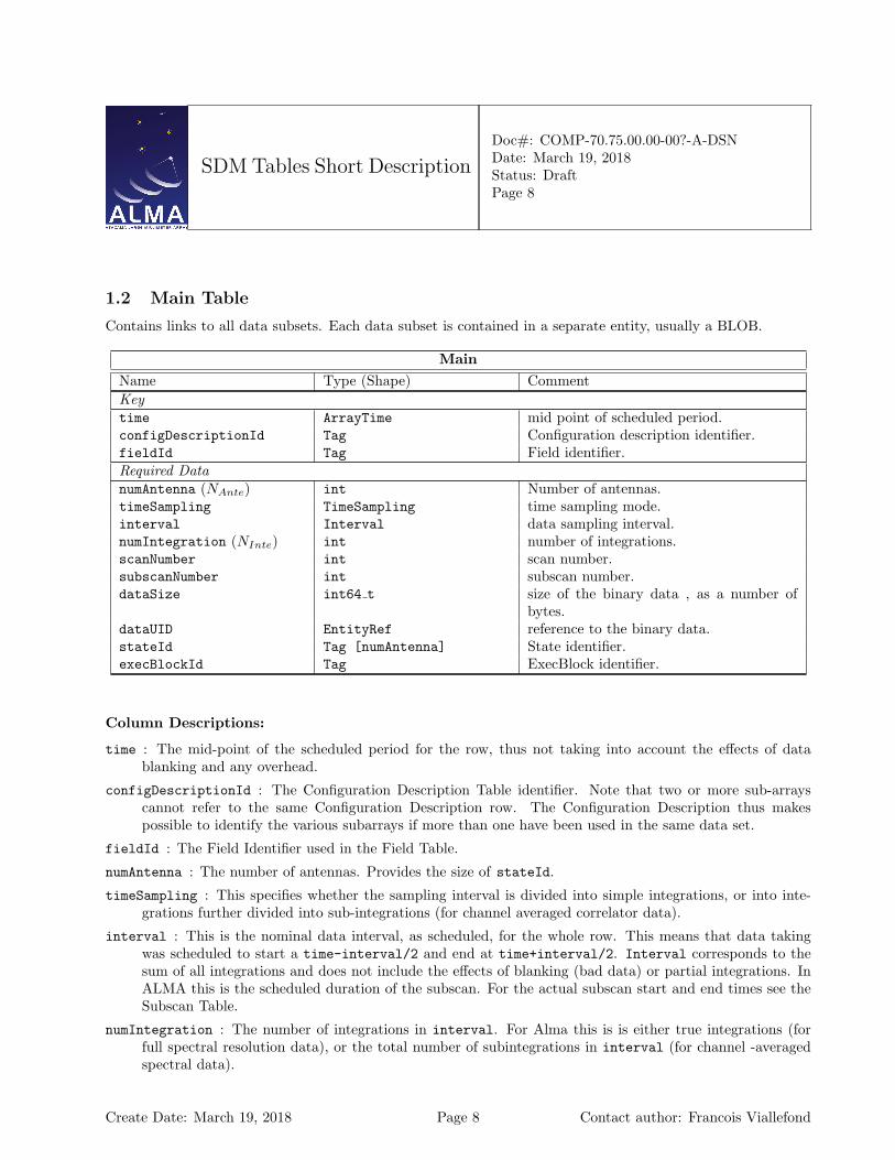
1.2 Main Table
Contains links to all data subsets. Each data subset is contained in a separate entity, usually a BLOB.
MainName Type (Shape) CommentKeytime ArrayTime mid point of scheduled period.configDescriptionId Tag Configuration description identifier.fieldId Tag Field identifier.Required DatanumAntenna (NAnte) int Number of antennas.timeSampling TimeSampling time sampling mode.interval Interval data sampling interval.numIntegration (NInte) int number of integrations.scanNumber int scan number.subscanNumber int subscan number.dataSize int64 t size of the binary data , as a number of
bytes.dataUID EntityRef reference to the binary data.stateId Tag [numAntenna] State identifier.execBlockId Tag ExecBlock identifier.
Column Descriptions:
time : The mid-point of the scheduled period for the row, thus not taking into account the effects of datablanking and any overhead.
configDescriptionId : The Configuration Description Table identifier. Note that two or more sub-arrayscannot refer to the same Configuration Description row. The Configuration Description thus makespossible to identify the various subarrays if more than one have been used in the same data set.
fieldId : The Field Identifier used in the Field Table.
numAntenna : The number of antennas. Provides the size of stateId.
timeSampling : This specifies whether the sampling interval is divided into simple integrations, or into inte-grations further divided into sub-integrations (for channel averaged correlator data).
interval : This is the nominal data interval, as scheduled, for the whole row. This means that data takingwas scheduled to start a time-interval/2 and end at time+interval/2. Interval corresponds to thesum of all integrations and does not include the effects of blanking (bad data) or partial integrations. InALMA this is the scheduled duration of the subscan. For the actual subscan start and end times see theSubscan Table.
numIntegration : The number of integrations in interval. For Alma this is is either true integrations (forfull spectral resolution data), or the total number of subintegrations in interval (for channel -averagedspectral data).
Create Date: March 19, 2018 Page 8 Contact author: Francois Viallefond

SDM Tables Short Description
Doc#: COMP-70.75.00.00-00?-A-DSNDate: March 19, 2018Status: DraftPage 9
scanNumber : In Alma a scan is an amount of data taken to reach a single result (e.g. a simple calibration).The scan numbers increment from 1 inside an Execution Block.
subscanNumber : In Alma a Subscan is the minimum amount of data taken by executing a single ControlCommand Language (CCL) command. There can be several data cells for each subscan correspondingto different backends (correlator, total power detectors) or different results of the same backend (channelaveraged or full-resolution data from a Correlator). In each scan there is at least one subscan.
dataSize : Total size, in bytes, of the binary data file.
dataUID : This is a string that specifies the data object.
stateId : The State indentifier used in the State Table.
execBlockId : The ExecBlock identifier used in the ExecBlock Table. For ALMA the ExecBlocks representeach execution of a Scheduling Block.
Create Date: March 19, 2018 Page 9 Contact author: Francois Viallefond
SDM Tables Short Description
Doc#: COMP-70.75.00.00-00?-A-DSNDate: March 19, 2018Status: DraftPage 10
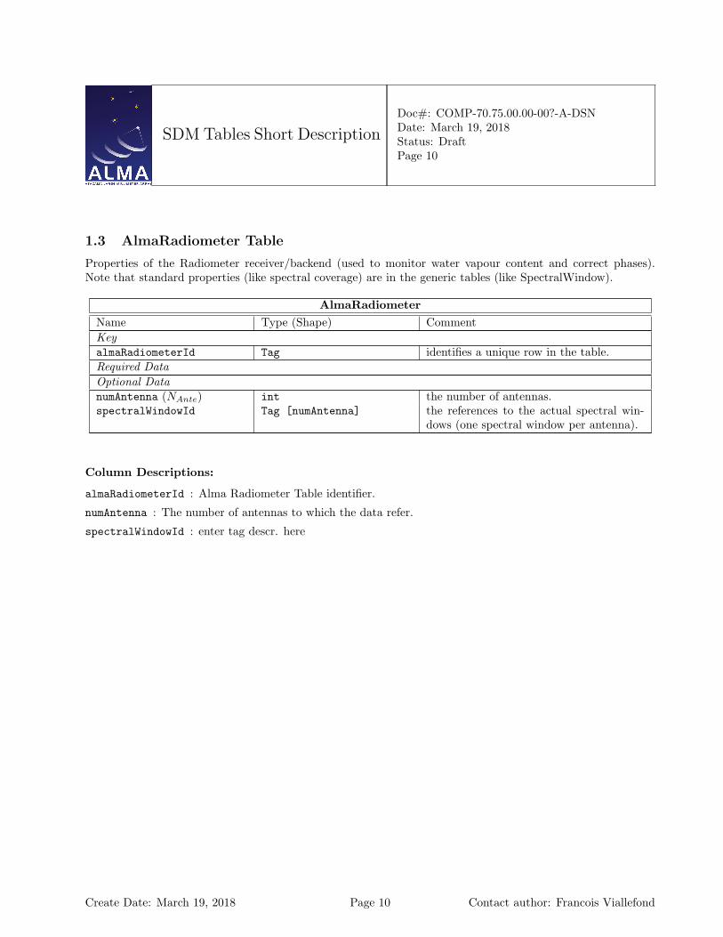
1.3 AlmaRadiometer Table
Properties of the Radiometer receiver/backend (used to monitor water vapour content and correct phases).Note that standard properties (like spectral coverage) are in the generic tables (like SpectralWindow).
AlmaRadiometerName Type (Shape) CommentKeyalmaRadiometerId Tag identifies a unique row in the table.Required DataOptional DatanumAntenna (NAnte) int the number of antennas.spectralWindowId Tag [numAntenna] the references to the actual spectral win-
dows (one spectral window per antenna).
Column Descriptions:
almaRadiometerId : Alma Radiometer Table identifier.
numAntenna : The number of antennas to which the data refer.
spectralWindowId : enter tag descr. here
Create Date: March 19, 2018 Page 10 Contact author: Francois Viallefond
SDM Tables Short Description
Doc#: COMP-70.75.00.00-00?-A-DSNDate: March 19, 2018Status: DraftPage 11
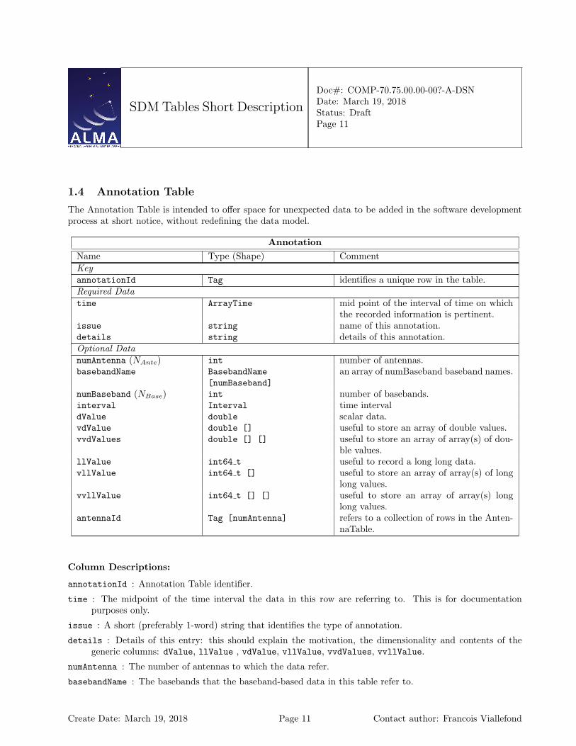
1.4 Annotation Table
The Annotation Table is intended to offer space for unexpected data to be added in the software developmentprocess at short notice, without redefining the data model.
AnnotationName Type (Shape) CommentKeyannotationId Tag identifies a unique row in the table.Required Datatime ArrayTime mid point of the interval of time on which
the recorded information is pertinent.issue string name of this annotation.details string details of this annotation.Optional DatanumAntenna (NAnte) int number of antennas.basebandName BasebandName
[numBaseband]an array of numBaseband baseband names.
numBaseband (NBase) int number of basebands.interval Interval time intervaldValue double scalar data.vdValue double [] useful to store an array of double values.vvdValues double [] [] useful to store an array of array(s) of dou-
ble values.llValue int64 t useful to record a long long data.vllValue int64 t [] useful to store an array of array(s) of long
long values.vvllValue int64 t [] [] useful to store an array of array(s) long
long values.antennaId Tag [numAntenna] refers to a collection of rows in the Anten-
naTable.
Column Descriptions:
annotationId : Annotation Table identifier.
time : The midpoint of the time interval the data in this row are referring to. This is for documentationpurposes only.
issue : A short (preferably 1-word) string that identifies the type of annotation.
details : Details of this entry: this should explain the motivation, the dimensionality and contents of thegeneric columns: dValue, llValue , vdValue, vllValue, vvdValues, vvllValue.
numAntenna : The number of antennas to which the data refer.
basebandName : The basebands that the baseband-based data in this table refer to.
Create Date: March 19, 2018 Page 11 Contact author: Francois Viallefond

SDM Tables Short Description
Doc#: COMP-70.75.00.00-00?-A-DSNDate: March 19, 2018Status: DraftPage 12
numBaseband : The number of basebands to which the data refer.
interval : Time interval during which the recorded information is pertinent.
dValue : space for a scalar floating-point number.
vdValue : space for a 1-dimensional array of floating-point data; shape must be made explicit in details.
vvdValues : space for a 2-dimensional array of floating-point data; shape must be made explicit in details.
llValue : space for a scalar integer.
vllValue : space for a 1-dimensional array of integer data; shape must be made explicit in details.
vvllValue : space for a 2-dimensional array of integer data; shape must be made explicit in details.
antennaId : Antenna Table identifier.
Create Date: March 19, 2018 Page 12 Contact author: Francois Viallefond
SDM Tables Short Description
Doc#: COMP-70.75.00.00-00?-A-DSNDate: March 19, 2018Status: DraftPage 13
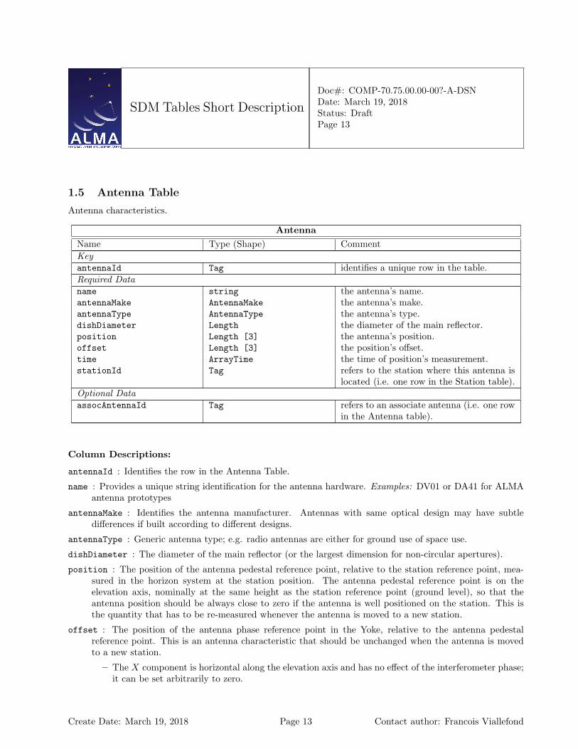
1.5 Antenna Table
Antenna characteristics.
AntennaName Type (Shape) CommentKeyantennaId Tag identifies a unique row in the table.Required Dataname string the antenna’s name.antennaMake AntennaMake the antenna’s make.antennaType AntennaType the antenna’s type.dishDiameter Length the diameter of the main reflector.position Length [3] the antenna’s position.offset Length [3] the position’s offset.time ArrayTime the time of position’s measurement.stationId Tag refers to the station where this antenna is
located (i.e. one row in the Station table).Optional DataassocAntennaId Tag refers to an associate antenna (i.e. one row
in the Antenna table).
Column Descriptions:
antennaId : Identifies the row in the Antenna Table.
name : Provides a unique string identification for the antenna hardware. Examples: DV01 or DA41 for ALMAantenna prototypes
antennaMake : Identifies the antenna manufacturer. Antennas with same optical design may have subtledifferences if built according to different designs.
antennaType : Generic antenna type; e.g. radio antennas are either for ground use of space use.
dishDiameter : The diameter of the main reflector (or the largest dimension for non-circular apertures).
position : The position of the antenna pedestal reference point, relative to the station reference point, mea-sured in the horizon system at the station position. The antenna pedestal reference point is on theelevation axis, nominally at the same height as the station reference point (ground level), so that theantenna position should be always close to zero if the antenna is well positioned on the station. This isthe quantity that has to be re-measured whenever the antenna is moved to a new station.
offset : The position of the antenna phase reference point in the Yoke, relative to the antenna pedestalreference point. This is an antenna characteristic that should be unchanged when the antenna is movedto a new station.
– The X component is horizontal along the elevation axis and has no effect of the interferometer phase;it can be set arbitrarily to zero.
Create Date: March 19, 2018 Page 13 Contact author: Francois Viallefond
SDM Tables Short Description
Doc#: COMP-70.75.00.00-00?-A-DSNDate: March 19, 2018Status: DraftPage 14
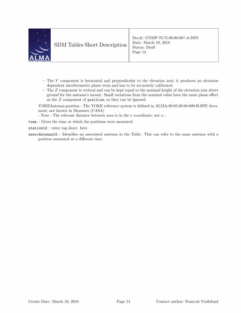
– The Y component is horizontal and perpendicular to the elevation axis; it produces an elevationdependent interferometer phase term and has to be accurately calibrated.
– The Z component is vertical and can be kept equal to the nominal height of the elevation axis aboveground for the antenna’s mount. Small variations from the nominal value have the same phase effectas the Z component of position, so they can be ignored.
YOKEAntenna.position - The YOKE reference system is defined in ALMA-80.05.00.00-009-B-SPE docu-ment; not known in Measures (CASA)- Note - The relevant distance between axes is in the y coordinate, not x...
time : Gives the time at which the positions were measured.
stationId : enter tag descr. here
assocAntennaId : Identifies an associated antenna in the Table. This can refer to the same antenna with aposition measured at a different time.
Create Date: March 19, 2018 Page 14 Contact author: Francois Viallefond
SDM Tables Short Description
Doc#: COMP-70.75.00.00-00?-A-DSNDate: March 19, 2018Status: DraftPage 15
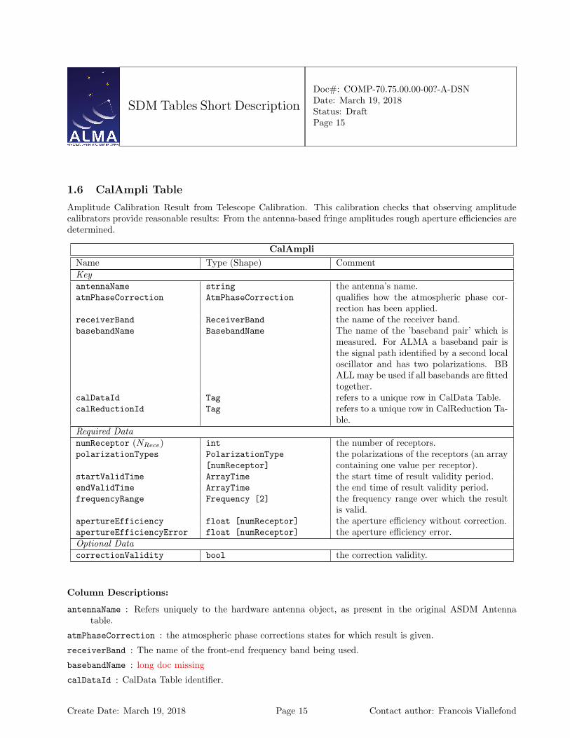
1.6 CalAmpli Table
Amplitude Calibration Result from Telescope Calibration. This calibration checks that observing amplitudecalibrators provide reasonable results: From the antenna-based fringe amplitudes rough aperture efficiencies aredetermined.
CalAmpliName Type (Shape) CommentKeyantennaName string the antenna’s name.atmPhaseCorrection AtmPhaseCorrection qualifies how the atmospheric phase cor-
rection has been applied.receiverBand ReceiverBand the name of the receiver band.basebandName BasebandName The name of the ’baseband pair’ which is
measured. For ALMA a baseband pair isthe signal path identified by a second localoscillator and has two polarizations. BBALL may be used if all basebands are fittedtogether.
calDataId Tag refers to a unique row in CalData Table.calReductionId Tag refers to a unique row in CalReduction Ta-
ble.Required DatanumReceptor (NRece) int the number of receptors.polarizationTypes PolarizationType
[numReceptor]the polarizations of the receptors (an arraycontaining one value per receptor).
startValidTime ArrayTime the start time of result validity period.endValidTime ArrayTime the end time of result validity period.frequencyRange Frequency [2] the frequency range over which the result
is valid.apertureEfficiency float [numReceptor] the aperture efficiency without correction.apertureEfficiencyError float [numReceptor] the aperture efficiency error.Optional DatacorrectionValidity bool the correction validity.
Column Descriptions:
antennaName : Refers uniquely to the hardware antenna object, as present in the original ASDM Antennatable.
atmPhaseCorrection : the atmospheric phase corrections states for which result is given.
receiverBand : The name of the front-end frequency band being used.
basebandName : long doc missing
calDataId : CalData Table identifier.
Create Date: March 19, 2018 Page 15 Contact author: Francois Viallefond

SDM Tables Short Description
Doc#: COMP-70.75.00.00-00?-A-DSNDate: March 19, 2018Status: DraftPage 16
calReductionId : CalReduction Table identifier.
numReceptor : The number or polarization receptors (one or two) for which the result is given.
polarizationTypes : The polarization types of the receptors being used.
startValidTime : The start of the time validity range for the result.
endValidTime : The end of the time validity range for the result.
frequencyRange : Frequency range over which the result is valid TOPO
apertureEfficiency : Antenna aperture efficiency with and/or without phase correction.
apertureEfficiencyError : Error on aperture efficiency measurement.
correctionValidity : Deduced validity of atmospheric path length correction (from Water Vapour Radiome-ters).
Create Date: March 19, 2018 Page 16 Contact author: Francois Viallefond
SDM Tables Short Description
Doc#: COMP-70.75.00.00-00?-A-DSNDate: March 19, 2018Status: DraftPage 17
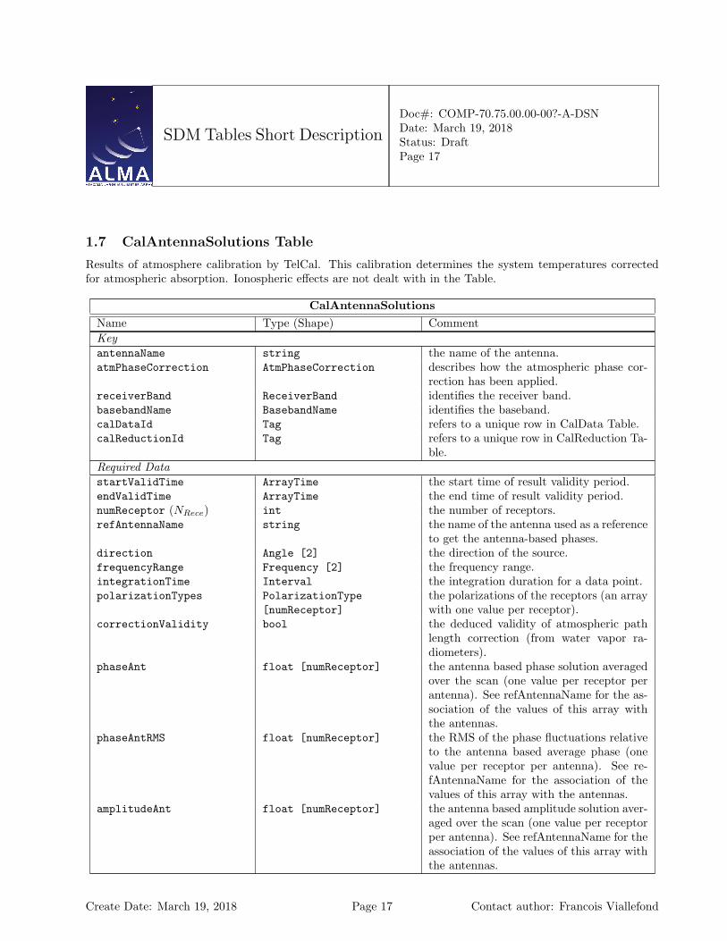
1.7 CalAntennaSolutions Table
Results of atmosphere calibration by TelCal. This calibration determines the system temperatures correctedfor atmospheric absorption. Ionospheric effects are not dealt with in the Table.
CalAntennaSolutionsName Type (Shape) CommentKeyantennaName string the name of the antenna.atmPhaseCorrection AtmPhaseCorrection describes how the atmospheric phase cor-
rection has been applied.receiverBand ReceiverBand identifies the receiver band.basebandName BasebandName identifies the baseband.calDataId Tag refers to a unique row in CalData Table.calReductionId Tag refers to a unique row in CalReduction Ta-
ble.Required DatastartValidTime ArrayTime the start time of result validity period.endValidTime ArrayTime the end time of result validity period.numReceptor (NRece) int the number of receptors.refAntennaName string the name of the antenna used as a reference
to get the antenna-based phases.direction Angle [2] the direction of the source.frequencyRange Frequency [2] the frequency range.integrationTime Interval the integration duration for a data point.polarizationTypes PolarizationType
[numReceptor]the polarizations of the receptors (an arraywith one value per receptor).
correctionValidity bool the deduced validity of atmospheric pathlength correction (from water vapor ra-diometers).
phaseAnt float [numReceptor] the antenna based phase solution averagedover the scan (one value per receptor perantenna). See refAntennaName for the as-sociation of the values of this array withthe antennas.
phaseAntRMS float [numReceptor] the RMS of the phase fluctuations relativeto the antenna based average phase (onevalue per receptor per antenna). See re-fAntennaName for the association of thevalues of this array with the antennas.
amplitudeAnt float [numReceptor] the antenna based amplitude solution aver-aged over the scan (one value per receptorper antenna). See refAntennaName for theassociation of the values of this array withthe antennas.
Create Date: March 19, 2018 Page 17 Contact author: Francois Viallefond

SDM Tables Short Description
Doc#: COMP-70.75.00.00-00?-A-DSNDate: March 19, 2018Status: DraftPage 18
CalAntennaSolutions – continued from previous pageName Type (Shape) CommentamplitudeAntRMS float [numReceptor] the antenna based amplitude solution aver-
aged over the scan (one value per receptorper antenna). See refAntennaName for theassociation of the values of this array withthe antennas.
Column Descriptions:
antennaName : Refers uniquely to the hardware antenna object, as present in the original ASDM Antennatable.
atmPhaseCorrection : The atmospheric phase corrections states for which result is given.
receiverBand : The name of the front-end frequency band being used.
basebandName : long doc missing
calDataId : CalData Table identifier.
calReductionId : CalReduction Table identifier.
startValidTime : The start of the time validity range for the result.
endValidTime : The end of the time validity range for the result.
numReceptor : The number or polarization receptors (one or two) for which the result is given.
refAntennaName : long doc missing
direction : The antenna pointing direction in horizontal coordinates. AZELNOWAntenna.position
frequencyRange : Frequency range over which the result is valid TOPO
integrationTime : Integration time on a data point, to calculate rms.
polarizationTypes : The polarization types of the receptors being used.
correctionValidity : Deduced validity of atmospheric path length correction (from Water Vapour Radiome-ters; remark: It is not clear that correctionValidity is really an array. What about its size?).
phaseAnt : long doc missing
phaseAntRMS : long doc missing
amplitudeAnt : long doc missing
amplitudeAntRMS : long doc missing
Create Date: March 19, 2018 Page 18 Contact author: Francois Viallefond

SDM Tables Short Description
Doc#: COMP-70.75.00.00-00?-A-DSNDate: March 19, 2018Status: DraftPage 19
1.8 CalAppPhase Table
The CalAppPhase table is relevant to the ALMA observatory when the antennas are being phased to form acoherent sum during the observation. For each scan, the table provides information about which antennas areincluded in the sum, their relative phase adjustments, the efficiency of the sum (relative to best performance)and the quality of each antenna participating in the system. This data is used in real-time to provide the phasedsum signal, and after the observation to analyze the result.
CalAppPhaseName Type (Shape) CommentKeybasebandName BasebandName identifies the baseband.scanNumber int The number of the scan processed by TEL-
CAL. Along with an ExecBlock Id (whichshould be ExecBlock 0 most of the time),the value of scanNumber can be used asthe key to retrieve informations related tothe scan (e.g. its start time).
calDataId Tag identifies a unique row in the CalData ta-ble.
calReductionId Tag identifies a unique row in the CalReductiontable.
Required DatastartValidTime ArrayTime start of phasing solution validity.endValidTime ArrayTime end of phasing solution validity.adjustTime ArrayTime The time of the last adjustment to the
phasing analysis via the ParameterTuninginterface.
adjustToken string A parameter supplied via theParameterTuning interface to indicatethe form of adjustment(s) made at adjust-Time. Note that TELCAL merely passesthis datum and adjustTime through tothis table.
phasingMode string The mode in which the phasing system isbeing operated.
numPhasedAntennas ( Np) int the number of antennas in phased sum, Np.phasedAntennas string
[numPhasedAntennas]the names of the phased antennas.
refAntennaIndex int the index of the reference antenna in thearray phasedAntennas . It must be an in-teger value in the interval [0, Np − 1].
Create Date: March 19, 2018 Page 19 Contact author: Francois Viallefond

SDM Tables Short Description
Doc#: COMP-70.75.00.00-00?-A-DSNDate: March 19, 2018Status: DraftPage 20
CalAppPhase – continued from previous pageName Type (Shape) CommentcandRefAntennaIndex int tne index of a candidate (new) reference
antenna in the array phasedAntennas; itmust be a integer in the interval [0, Np−1].
phasePacking string how to unpack phaseValues.numReceptors ( Nr) int the number of receptors per antenna,
Nr.The number (Nr ≤ 2) of receptors perantenna, usually two (polarizations), but itmight be one in special cases.
numChannels ( Nd) int the number of data channels, Nd.numPhaseValues ( Nv) int The number of phase data values present
in the table, Nv.phaseValues float [numPhaseValues] the array of phase data values.numCompare ( Nc) int the number of comparison antennas, Nc.numEfficiencies ( Ne) int the number of efficiencies, Ne.compareArray string [numCompare] the names of the comparison antennas.efficiencyIndices int [numEfficiencies] indices of the antenna(s) in compareArray
used to calculate efficiencies; they must bedistinct integers in the interval [0, Nc].
efficiencies float [numEfficiencies][numChannels]
an array of efficiencies of phased sum.
quality float[numPhasedAntennas+numCompare]
quality of phased antennas.
phasedSumAntenna string the name of the phased sum antenna.Optional DatatypeSupports string encoding of supporting data values.numSupports ( Ns) int the number of supporting data values, Ns.phaseSupports float [numSupports] an array of supporting data values.
Column Descriptions:
basebandName : identifies the baseband.
scanNumber : The number of the scan processed by TELCAL. Along with an ExecBlock Id (which should beExecBlock 0 most of thetime), thevalue of scanNumber can be used as the key to retrieve informationsrelated to the scan (e.g. its start time).
calDataId : identifies a unique row in the CalData table.
calReductionId : identifies a unique row in the CalReduction table.
startValidTime : The start of the interval in which the phase solution was calculated. Normally the first fewseconds of each scan include data before the previous slow phasing solution can be applied, so the validinterval corresponds to the last phasing correction.
Create Date: March 19, 2018 Page 20 Contact author: Francois Viallefond
SDM Tables Short Description
Doc#: COMP-70.75.00.00-00?-A-DSNDate: March 19, 2018Status: DraftPage 21
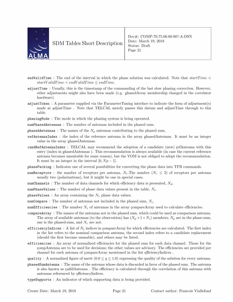
endValidTime : The end of the interval in which the phase solution was calculated. Note that startT ime <startV alidT ime < endV alidT ime ≤ endT ime.
adjustTime : Usually, this is the timestamp of the commanding of the last slow phasing correction. However,other adjustments might also have been made (e.g. phasedArray membership changed in the correlatorhardware).
adjustToken : A parameter supplied via the ParameterTuning interface to indicate the form of adjustment(s)made at adjustTime . Note that TELCAL merely passes this datum and adjustTime through to thistable.
phasingMode : The mode in which the phasing system is being operated.
numPhasedAntennas : The number of antennas included in the phased sum.
phasedAntennas : The names of the Np antennas contributing to the phased sum.
refAntennaIndex : the index of the reference antenna in the array phasedAntennas. It must be an integervalue in the array phasedAntennas.
candRefAntennaIndex : TELCAL may recommend the adoption of a candidate (new) refAntenna with thisentry (index in phasedAntennas ). This recommendation is always available (in case the current referenceantenna becomes unsuitable for some reason), but the VOM is not obliged to adopt the recommendation.It must be an integer in the interval [0, Np− 1].
phasePacking : Indicates one of several possibilities for converting the phase data into TFB commands.
numReceptors : the number of receptors per antenna, Nr.The number (Nr ≤ 2) of receptors per antennausually two (polarizations), but it might be one in special cases.
numChannels : The number of data channels for which efficiency data is presented, Nd.
numPhaseValues : The number of phase data values present in the table, Nv.
phaseValues : An array containing the Nv phase data values.
numCompare : The number of antennas not included in the phased sum, Nc.
numEfficiencies : The number Ne of antennas in the array compareArray used to calculate efficiencies.
compareArray : The names of the antennas not in the phased sum, which could be used as comparison antenna.The array of available antennas (to the observation) has (Np +1+Nc) members; Np are in the phase-sum,one is the phased-sum, and Nc are not.
efficiencyIndices : A list of Ne indices in compareArray for which efficiencies are calculated. The first indexin the list refers to the nominal comparison antenna, the second index refers to a candidate replacement(should the first become unusable), and others may be listed.
efficiencies : An array of normalized efficiencies for the phased sum for each data channel. Those for thecompAntenna are to be used for decisions; the other values are advisory. The efficiencies are provided perchannel for each antenna of compareArray mentioned in the list efficiencyIndices .
quality : A normalized figure of merit (0.0 ≤ q ≤ 1.0) expressing the quality of the solution for every antenna.
phasedSumAntenna : The name of the antenna whose data is discarded in favor of the phased sum. The antennais also known as cai63Antenna . The efficiency is calculated through the correlation of this antenna withantennas referenced by efficiencyIndices.
typeSupports : An indicator of which supporting data is being provided.
Create Date: March 19, 2018 Page 21 Contact author: Francois Viallefond
SDM Tables Short Description
Doc#: COMP-70.75.00.00-00?-A-DSNDate: March 19, 2018Status: DraftPage 22
numSupports : The number of supporting data values present, Ns.
phaseSupports : An array of Ns supporting data values. The presence and use of this array is unspecified; butmight include channel average frequencies or supplementary quality data as an assist in the implementa-tion. (Indeed, there is a long list of such items that TelCal could compute.)
Create Date: March 19, 2018 Page 22 Contact author: Francois Viallefond
SDM Tables Short Description
Doc#: COMP-70.75.00.00-00?-A-DSNDate: March 19, 2018Status: DraftPage 23
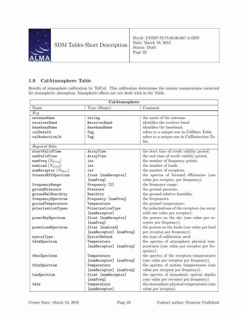
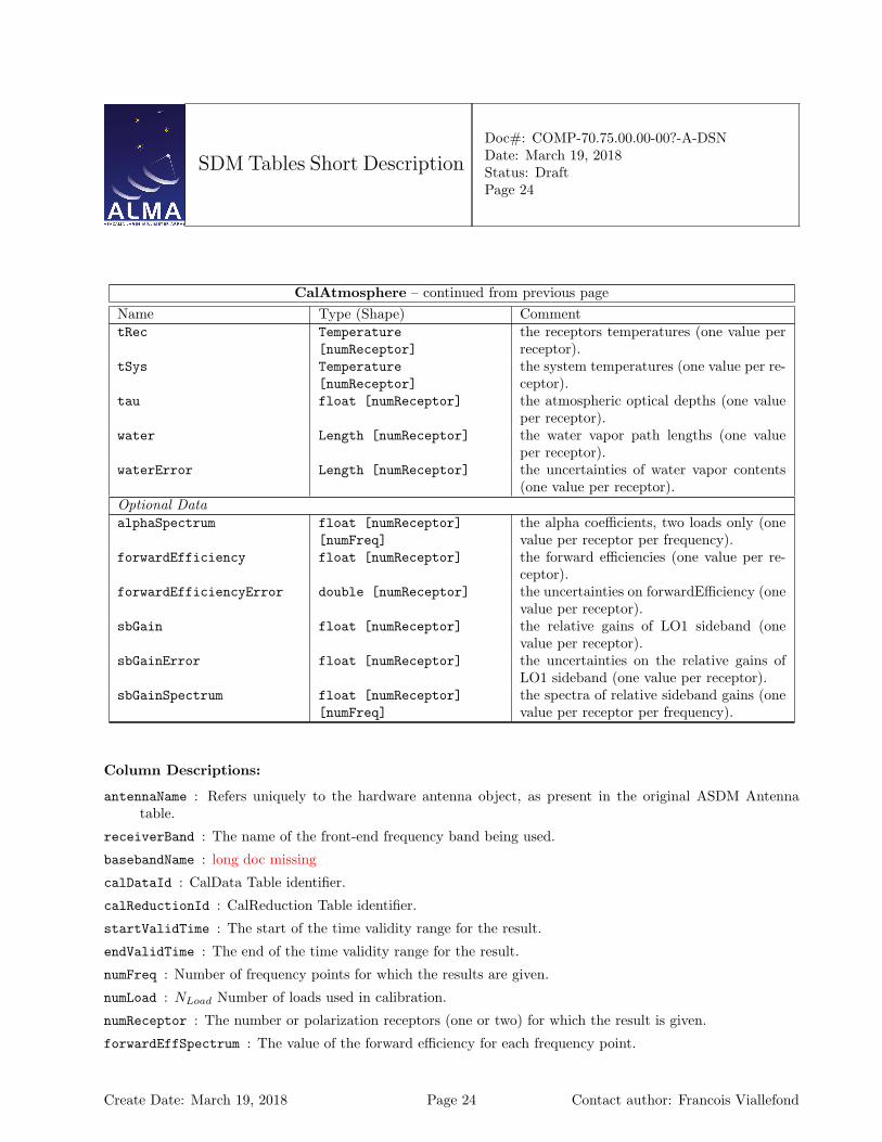
1.9 CalAtmosphere Table
Results of atmosphere calibration by TelCal. This calibration determines the system temperatures correctedfor atmospheric absorption. Ionospheric effects are not dealt with in the Table.
CalAtmosphereName Type (Shape) CommentKeyantennaName string the name of the antenna.receiverBand ReceiverBand identifies the receiver band.basebandName BasebandName identifies the baseband.calDataId Tag refers to a unique row in CalData Table.calReductionId Tag refers to a unique row in CalReduction Ta-
ble.Required DatastartValidTime ArrayTime the start time of result validity period.endValidTime ArrayTime the end time of result validity period.numFreq (NFreq) int the number of frequency points.numLoad (NLoad) int the number of loads.numReceptor (NRece) int the number of receptors.forwardEffSpectrum float [numReceptor]
[numFreq]the spectra of forward efficiencies (onevalue per receptor, per frequency).
frequencyRange Frequency [2] the frequency range.groundPressure Pressure the ground pressure.groundRelHumidity Humidity the ground relative humidity.frequencySpectrum Frequency [numFreq] the frequencies.groundTemperature Temperature the ground temperature.polarizationTypes PolarizationType
[numReceptor]the polarizations of the receptors (an arraywith one value per receptor).
powerSkySpectrum float [numReceptor][numFreq]
the powers on the sky (one value per re-ceptor per frequency).
powerLoadSpectrum float [numLoad][numReceptor] [numFreq]
the powers on the loads (one value per loadper receptor per frequency).
syscalType SyscalMethod the type of calibration used.tAtmSpectrum Temperature
[numReceptor] [numFreq]the spectra of atmosphere physical tem-peratures (one value per receptor per fre-quency).
tRecSpectrum Temperature[numReceptor] [numFreq]
the spectra of the receptors temperatures(one value per receptor per frequency).
tSysSpectrum Temperature[numReceptor] [numFreq]
the spectra of system temperatures (onevalue per receptor per frequency).
tauSpectrum float [numReceptor][numFreq]
the spectra of atmosheric optical depths(one value per receptor per frequency).
tAtm Temperature[numReceptor]
the atmosphere physical temperatures (onevalue per receptor).
Create Date: March 19, 2018 Page 23 Contact author: Francois Viallefond
SDM Tables Short Description
Doc#: COMP-70.75.00.00-00?-A-DSNDate: March 19, 2018Status: DraftPage 24
CalAtmosphere – continued from previous pageName Type (Shape) CommenttRec Temperature
[numReceptor]the receptors temperatures (one value perreceptor).
tSys Temperature[numReceptor]
the system temperatures (one value per re-ceptor).
tau float [numReceptor] the atmospheric optical depths (one valueper receptor).
water Length [numReceptor] the water vapor path lengths (one valueper receptor).
waterError Length [numReceptor] the uncertainties of water vapor contents(one value per receptor).
Optional DataalphaSpectrum float [numReceptor]
[numFreq]the alpha coefficients, two loads only (onevalue per receptor per frequency).
forwardEfficiency float [numReceptor] the forward efficiencies (one value per re-ceptor).
forwardEfficiencyError double [numReceptor] the uncertainties on forwardEfficiency (onevalue per receptor).
sbGain float [numReceptor] the relative gains of LO1 sideband (onevalue per receptor).
sbGainError float [numReceptor] the uncertainties on the relative gains ofLO1 sideband (one value per receptor).
sbGainSpectrum float [numReceptor][numFreq]
the spectra of relative sideband gains (onevalue per receptor per frequency).
Column Descriptions:
antennaName : Refers uniquely to the hardware antenna object, as present in the original ASDM Antennatable.
receiverBand : The name of the front-end frequency band being used.
basebandName : long doc missing
calDataId : CalData Table identifier.
calReductionId : CalReduction Table identifier.
startValidTime : The start of the time validity range for the result.
endValidTime : The end of the time validity range for the result.
numFreq : Number of frequency points for which the results are given.
numLoad : NLoad Number of loads used in calibration.
numReceptor : The number or polarization receptors (one or two) for which the result is given.
forwardEffSpectrum : The value of the forward efficiency for each frequency point.
Create Date: March 19, 2018 Page 24 Contact author: Francois Viallefond

SDM Tables Short Description
Doc#: COMP-70.75.00.00-00?-A-DSNDate: March 19, 2018Status: DraftPage 25
frequencyRange : Frequency range over which the result is valid TOPO
groundPressure : The atmospheric pressure at the altitude of the observatory.
groundRelHumidity : The relative atmospheric humidity (%) at the altitude of the observatory.
frequencySpectrum : The frequency values for which the results are given.
groundTemperature : The ambient temperature at the observatory.
polarizationTypes : The polarization types of the receptors being used.
powerSkySpectrum : Observed power on sky.
powerLoadSpectrum : Observed power on loads.
syscalType : The type of calibration used: a single-direction measurement, or a series of measurements atdifferent elevations (’SkyDip’)
tAtmSpectrum : The value of atmosphere physical temperature for each frequency point.
tRecSpectrum : The value of the receiver temperature for each frequency point.
tSysSpectrum : The value of the system temperature for each frequency point.
tauSpectrum : The value of the optical depth for each frequency point.
tAtm : The physical temperature of the atmosphere absorbing layers.
tRec : The receiver noise temperature (the reference plane is at the level where the calibration loads are insertedin the signal path).
tSys : The system temperature (corrected for atmospheric absorption and antenna losses).
tau : The optical depth of the atmosphere along the line of sight.
water : The amount of precipitable water vapour in the atmosphere.
waterError : The uncertainty of the amount of precipitable water vapour in the atmosphere.
alphaSpectrum : alpha coefficient (two-load only); see Amplitude Calibration steps memo.
forwardEfficiency : This is the coupling factor to the sky, that is the fraction of the antenna beam that seesthe emission from the atmosphere.
forwardEfficiencyError : The uncertainty of forwardEfficiency
sbGain : The relative gain of the side band. This is the ratio of the gain in the first LO sideband used to obtainthe frequencyRange relative to the total (dual-sideband) gain.
sbGainError : Uncertainty on sbGain.
sbGainSpectrum : The value of the relative side band gain for each spectral point. Optional for EVLA,mandatory for ALMA.
Create Date: March 19, 2018 Page 25 Contact author: Francois Viallefond
SDM Tables Short Description
Doc#: COMP-70.75.00.00-00?-A-DSNDate: March 19, 2018Status: DraftPage 26
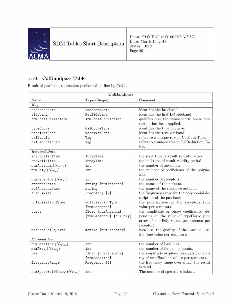
1.10 CalBandpass Table
Result of passband calibration performed on-line by TelCal.
CalBandpassName Type (Shape) CommentKeybasebandName BasebandName identifies the baseband.sideband NetSideband identifies the first LO sideband.atmPhaseCorrection AtmPhaseCorrection qualifies how the atmospheric phase cor-
rection has been applied.typeCurve CalCurveType identifies the type of curve.receiverBand ReceiverBand identifies the receiver band.calDataId Tag refers to a unique row in CalData Table.calReductionId Tag refers to a unique row in CalReduction Ta-
ble.Required DatastartValidTime ArrayTime the start time of result validity period.endValidTime ArrayTime the end time of result validity period.numAntenna (NAnte) int the number of antennas.numPoly (NPoly) int the number of coefficients of the polyno-
mial.numReceptor (NRece) int the number of receptors.antennaNames string [numAntenna] the names of the antennas.refAntennaName string the name of the reference antenna.freqLimits Frequency [2] the frequency range for the polynomial de-
scription of the passband.polarizationTypes PolarizationType
[numReceptor]the polarizations of the receptors (onevalue per receptor).
curve float [numAntenna][numReceptor] [numPoly]
the amplitude or phase coefficients, de-pending on the value of typeCurve (onearray of numPoly values per antenna perreceptor).
reducedChiSquared double [numReceptor] measures the quality of the least squaresfits (one value per receptor).
Optional DatanumBaseline (NBase) int the number of baselines.numFreq (NFreq) int the number of frequency points.rms float [numReceptor]
[numBaseline]the amplitude or phase residuals ( one ar-ray of numBaseline values per receptor).
frequencyRange Frequency [2] the frequency range over which the resultis valid.
numSpectralWindow (NSpec) int The number of spectral windows.
Create Date: March 19, 2018 Page 26 Contact author: Francois Viallefond

SDM Tables Short Description
Doc#: COMP-70.75.00.00-00?-A-DSNDate: March 19, 2018Status: DraftPage 27
CalBandpass – continued from previous pageName Type (Shape) CommentchanFreqStart Frequency
[numSpectralWindow]the frequency of the first channel.
chanFreqStep Frequency[numSpectralWindow]
the increment between two successive fre-quencies.
numSpectralWindowChan(NSpec)
int [numSpectralWindow] The number of channels for each spectralwindow.
spectrum float [numAntenna][numReceptor] [numFreq]
The antenna-based spectrum per receptoraveraging over the entire scan range.
Column Descriptions:
basebandName : The name of the ’baseband pair’ which is measured. For ALMA a baseband pair is the signalpath identified by a second local oscillator and has two polarizations. BB ALL may be used if all basebandsare fitted together.
sideband : First LO Sideband: For sideband-separated spectra one must use different bandpasses for eachindividual sideband.
atmPhaseCorrection : the atmospheric phase corrections states for which result is given.
typeCurve : Defines the quantity which is fitted: amplitude ot phase.
receiverBand : The name of the front-end frequency band being used.
calDataId : CalData Table identifier.
calReductionId : CalReduction Table identifier.
startValidTime : The start of the time validity range for the result.
endValidTime : The end of the time validity range for the result.
numAntenna : Number of antennas for which the result is valid.
numPoly : Number of polynomial coefficients.
numReceptor : The number or polarization receptors (one or two) for which the result is given.
antennaNames : Refer uniquely to the hardware antenna object, as present in the original ASDM Antennatable.
refAntennaName : The name of the antenna used as reference to get the antenna-based phases.
freqLimits : The frequency limits for the polynomial description of the passband. This frequency interval isreduced to the (-1, 1) interval over which the Chebychev polynomials are defined.
polarizationTypes : The polarization types of the receptors being used.
curve : The amplitude or phase coefficients.
reducedChiSquared : Reduced χ2 indicating the quality of the least-squares fit. This is a single number foreach polarization as the baselines are to be fitted consistently.
Create Date: March 19, 2018 Page 27 Contact author: Francois Viallefond

SDM Tables Short Description
Doc#: COMP-70.75.00.00-00?-A-DSNDate: March 19, 2018Status: DraftPage 28
numBaseline : Number of baselines for which the result is given
numFreq : Number of frequency points for which the results are given.
rms : The rms of the amplitude/phase residuals for each baseline/polarisation.
frequencyRange : Frequency range over which the result is valid TOPO
numSpectralWindow : long doc missing
chanFreqStart : long doc missing
chanFreqStep : long doc missing
numSpectralWindowChan : long doc missing
spectrum : long doc missing
Create Date: March 19, 2018 Page 28 Contact author: Francois Viallefond
SDM Tables Short Description
Doc#: COMP-70.75.00.00-00?-A-DSNDate: March 19, 2018Status: DraftPage 29
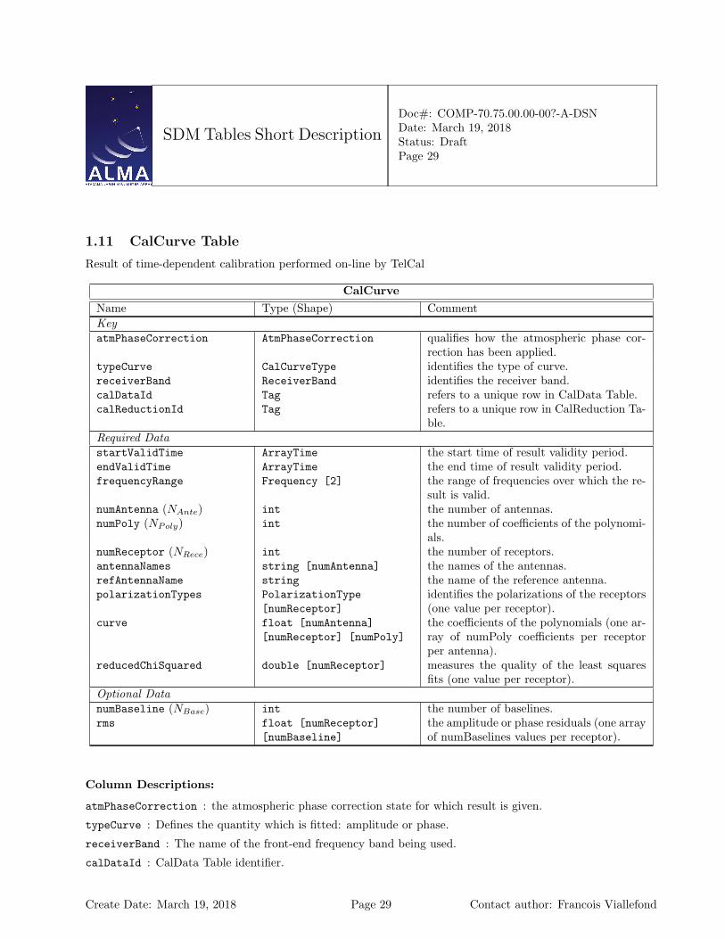
1.11 CalCurve Table
Result of time-dependent calibration performed on-line by TelCal
CalCurveName Type (Shape) CommentKeyatmPhaseCorrection AtmPhaseCorrection qualifies how the atmospheric phase cor-
rection has been applied.typeCurve CalCurveType identifies the type of curve.receiverBand ReceiverBand identifies the receiver band.calDataId Tag refers to a unique row in CalData Table.calReductionId Tag refers to a unique row in CalReduction Ta-
ble.Required DatastartValidTime ArrayTime the start time of result validity period.endValidTime ArrayTime the end time of result validity period.frequencyRange Frequency [2] the range of frequencies over which the re-
sult is valid.numAntenna (NAnte) int the number of antennas.numPoly (NPoly) int the number of coefficients of the polynomi-
als.numReceptor (NRece) int the number of receptors.antennaNames string [numAntenna] the names of the antennas.refAntennaName string the name of the reference antenna.polarizationTypes PolarizationType
[numReceptor]identifies the polarizations of the receptors(one value per receptor).
curve float [numAntenna][numReceptor] [numPoly]
the coefficients of the polynomials (one ar-ray of numPoly coefficients per receptorper antenna).
reducedChiSquared double [numReceptor] measures the quality of the least squaresfits (one value per receptor).
Optional DatanumBaseline (NBase) int the number of baselines.rms float [numReceptor]
[numBaseline]the amplitude or phase residuals (one arrayof numBaselines values per receptor).
Column Descriptions:
atmPhaseCorrection : the atmospheric phase correction state for which result is given.
typeCurve : Defines the quantity which is fitted: amplitude or phase.
receiverBand : The name of the front-end frequency band being used.
calDataId : CalData Table identifier.
Create Date: March 19, 2018 Page 29 Contact author: Francois Viallefond
SDM Tables Short Description
Doc#: COMP-70.75.00.00-00?-A-DSNDate: March 19, 2018Status: DraftPage 30
calReductionId : CalReduction Table identifier.
startValidTime : The start of the time validity range for the result.
endValidTime : The end of the time validity range for the result.
frequencyRange : Frequency range over which the result is valid. TOPO
numAntenna : Number of antennas for which the result is valid.
numPoly : The number of coefficients in the Chebichev polynomials used to fit the data.
numReceptor : The number or polarization receptors (one or two) for which the result is given.
antennaNames : Refer uniquely to the hardware antenna object, as present in the original ASDM Antennatable.
refAntennaName : The name of the antenna used as reference to get the antenna-based phases.
polarizationTypes : The polarization types of the receptors being used.
curve : These are Chebichev polynomial coefficients. The interval between startValidTime and endValidTimeis reduced to the −1, 1 interval over which the Chebychev coefficients are defined. For interferometeramplitude, data is expressed in terms of correlation coefficient; for interferomete phase, coefficients aregiven in radians.
reducedChiSquared : Reduced χ2 indicating the quality of the least-squares fit.
numBaseline : Number of baselines ffor which the result is given.
rms : The root means square deviations of fit residuals.
Create Date: March 19, 2018 Page 30 Contact author: Francois Viallefond
SDM Tables Short Description
Doc#: COMP-70.75.00.00-00?-A-DSNDate: March 19, 2018Status: DraftPage 31
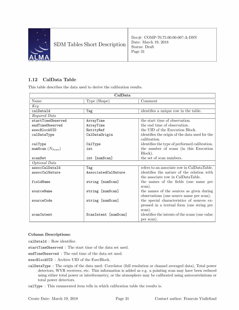
1.12 CalData Table
This table describes the data used to derive the calibration results.
CalDataName Type (Shape) CommentKeycalDataId Tag identifies a unique row in the table.Required DatastartTimeObserved ArrayTime the start time of observation.endTimeObserved ArrayTime the end time of observation.execBlockUID EntityRef the UID of the Execution Block.calDataType CalDataOrigin identifies the origin of the data used for the
calibration.calType CalType identifies the type of performed calibration.numScan (NScan) int the number of scans (in this Execution
Block).scanSet int [numScan] the set of scan numbers.Optional DataassocCalDataId Tag refers to an associate row in CalDataTable.assocCalNature AssociatedCalNature identifies the nature of the relation with
the associate row in CalDataTable.fieldName string [numScan] the names of the fields (one name per
scan).sourceName string [numScan] the names of the sources as given during
observations (one source name per scan).sourceCode string [numScan] the special characteristics of sources ex-
pressed in a textual form (one string perscan).
scanIntent ScanIntent [numScan] identifies the intents of the scans (one valueper scan).
Column Descriptions:
calDataId : Row identifier.
startTimeObserved : The start time of the data set used.
endTimeObserved : The end time of the data set used.
execBlockUID : Archive UID of the ExecBlock.
calDataType : The origin of the data used: Correlator (full resolution or channel averaged data), Total powerdetectors, WVR receivers, etc. This information is added as e.g. a pointing scan may have been reducedusing either total power or interferometry, or the atmosphere may be calibrated using autocorrelations ortotal power detectors.
calType : This enumerated item tells in which calibration table the results is.
Create Date: March 19, 2018 Page 31 Contact author: Francois Viallefond

SDM Tables Short Description
Doc#: COMP-70.75.00.00-00?-A-DSNDate: March 19, 2018Status: DraftPage 32
numScan : The number of scans in the scan set used.
scanSet : The list of scan numbers in the set of scans used.
assocCalDataId : This is used to chain data sets obtained in different ExecBlocks, for which scan numbersare re-used.
assocCalNature : Nature of the association established by assocCalDataId. Normally this is used to refer todata in different execution blocks, for which scan numbers may be re-used.
fieldName : The name of the field the array was aimed at.
sourceName : Names of the sources as given during observations.
sourceCode : Special characteristics of source, e.g. passband calibrator, phase calibrator, flux calibrator.
scanIntent : The list of the intents associated with each scan in the data set.
Create Date: March 19, 2018 Page 32 Contact author: Francois Viallefond
SDM Tables Short Description
Doc#: COMP-70.75.00.00-00?-A-DSNDate: March 19, 2018Status: DraftPage 33
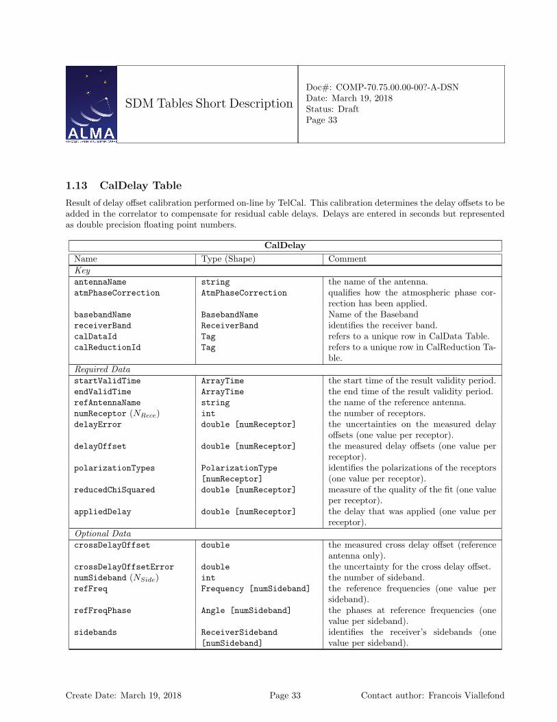
1.13 CalDelay Table
Result of delay offset calibration performed on-line by TelCal. This calibration determines the delay offsets to beadded in the correlator to compensate for residual cable delays. Delays are entered in seconds but representedas double precision floating point numbers.
CalDelayName Type (Shape) CommentKeyantennaName string the name of the antenna.atmPhaseCorrection AtmPhaseCorrection qualifies how the atmospheric phase cor-
rection has been applied.basebandName BasebandName Name of the BasebandreceiverBand ReceiverBand identifies the receiver band.calDataId Tag refers to a unique row in CalData Table.calReductionId Tag refers to a unique row in CalReduction Ta-
ble.Required DatastartValidTime ArrayTime the start time of the result validity period.endValidTime ArrayTime the end time of the result validity period.refAntennaName string the name of the reference antenna.numReceptor (NRece) int the number of receptors.delayError double [numReceptor] the uncertainties on the measured delay
offsets (one value per receptor).delayOffset double [numReceptor] the measured delay offsets (one value per
receptor).polarizationTypes PolarizationType
[numReceptor]identifies the polarizations of the receptors(one value per receptor).
reducedChiSquared double [numReceptor] measure of the quality of the fit (one valueper receptor).
appliedDelay double [numReceptor] the delay that was applied (one value perreceptor).
Optional DatacrossDelayOffset double the measured cross delay offset (reference
antenna only).crossDelayOffsetError double the uncertainty for the cross delay offset.numSideband (NSide) int the number of sideband.refFreq Frequency [numSideband] the reference frequencies (one value per
sideband).refFreqPhase Angle [numSideband] the phases at reference frequencies (one
value per sideband).sidebands ReceiverSideband
[numSideband]identifies the receiver’s sidebands (onevalue per sideband).
Create Date: March 19, 2018 Page 33 Contact author: Francois Viallefond
SDM Tables Short Description
Doc#: COMP-70.75.00.00-00?-A-DSNDate: March 19, 2018Status: DraftPage 34
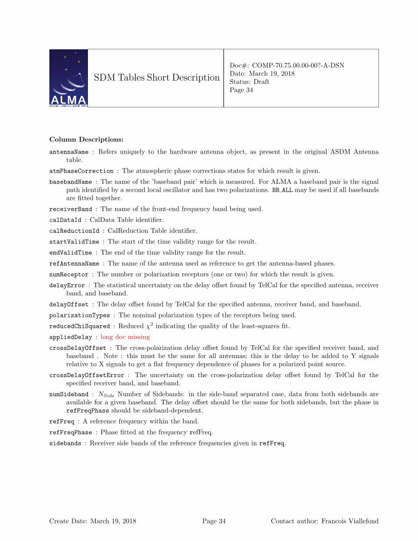
Column Descriptions:
antennaName : Refers uniquely to the hardware antenna object, as present in the original ASDM Antennatable.
atmPhaseCorrection : The atmospheric phase corrections states for which result is given.
basebandName : The name of the ’baseband pair’ which is measured. For ALMA a baseband pair is the signalpath identified by a second local oscillator and has two polarizations. BB ALL may be used if all basebandsare fitted together.
receiverBand : The name of the front-end frequency band being used.
calDataId : CalData Table identifier.
calReductionId : CalReduction Table identifier.
startValidTime : The start of the time validity range for the result.
endValidTime : The end of the time validity range for the result.
refAntennaName : The name of the antenna used as reference to get the antenna-based phases.
numReceptor : The number or polarization receptors (one or two) for which the result is given.
delayError : The statistical uncertainty on the delay offset found by TelCal for the specified antenna, receiverband, and baseband.
delayOffset : The delay offset found by TelCal for the specified antenna, receiver band, and baseband.
polarizationTypes : The nominal polarization types of the receptors being used.
reducedChiSquared : Reduced χ2 indicating the quality of the least-squares fit.
appliedDelay : long doc missing
crossDelayOffset : The cross-polarization delay offset found by TelCal for the specified receiver band, andbaseband . Note : this must be the same for all antennas; this is the delay to be added to Y signalsrelative to X signals to get a flat frequency dependence of phases for a polarized point source.
crossDelayOffsetError : The uncertainty on the cross-polarization delay offset found by TelCal for thespecified receiver band, and baseband.
numSideband : NSide Number of Sidebands: in the side-band separated case, data from both sidebands areavailable for a given baseband. The delay offset should be the same for both sidebands, but the phase inrefFreqPhase should be sideband-dependent.
refFreq : A reference frequency within the band.
refFreqPhase : Phase fitted at the frequency refFreq.
sidebands : Receiver side bands of the reference frequencies given in refFreq.
Create Date: March 19, 2018 Page 34 Contact author: Francois Viallefond
SDM Tables Short Description
Doc#: COMP-70.75.00.00-00?-A-DSNDate: March 19, 2018Status: DraftPage 35
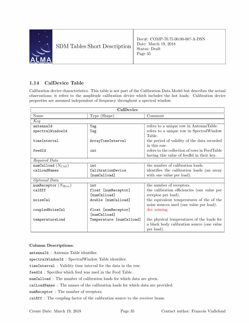
1.14 CalDevice Table
Calibration device characteristics. This table is not part of the Calibration Data Model but describes the actualobservations; it refers to the amplitude calibration device which includes the hot loads. Calibration deviceproperties are assumed independent of frequency throughout a spectral window.
CalDeviceName Type (Shape) CommentKeyantennaId Tag refers to a unique row in AntennaTable.spectralWindowId Tag refers to a unique row in SpectralWindow
Table.timeInterval ArrayTimeInterval the period of validity of the data recorded
in this row.feedId int refers to the collection of rows in FeedTable
having this value of feedId in their key.Required DatanumCalload (NCall) int the number of calibration loads.calLoadNames CalibrationDevice
[numCalload]identifies the calibration loads (an arraywith one value per load).
Optional DatanumReceptor (NRece) int the number of receptors.calEff float [numReceptor]
[numCalload]the calibration efficiencies (one value perreceptor per load).
noiseCal double [numCalload] the equivalent temperatures of the of thenoise sources used (one value per load).
coupledNoiseCal float [numReceptor][numCalload]
doc missing
temperatureLoad Temperature [numCalload] the physical temperatures of the loads fora black body calibration source (one valueper load).
Column Descriptions:
antennaId : Antenna Table identifier.
spectralWindowId : SpectralWindow Table identifier.
timeInterval : Validity time interval for the data in the row.
feedId : Specifies which feed was used in the Feed Table.
numCalload : The number of calibration loads for which data are given.
calLoadNames : The names of the calibration loads for which data are provided.
numReceptor : The number of receptors.
calEff : The coupling factor of the calibration source to the receiver beam.
Create Date: March 19, 2018 Page 35 Contact author: Francois Viallefond

SDM Tables Short Description
Doc#: COMP-70.75.00.00-00?-A-DSNDate: March 19, 2018Status: DraftPage 36
noiseCal : The equivalent temperature of the noise source used.
coupledNoiseCal : missing
temperatureLoad : The physical temperature of the load (for a black-body calibration source).
Create Date: March 19, 2018 Page 36 Contact author: Francois Viallefond
SDM Tables Short Description
Doc#: COMP-70.75.00.00-00?-A-DSNDate: March 19, 2018Status: DraftPage 37
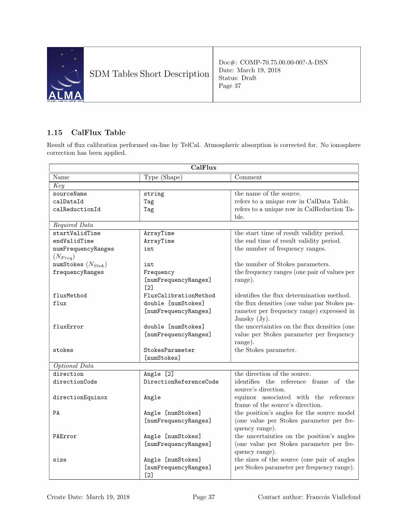
1.15 CalFlux Table
Result of flux calibration performed on-line by TelCal. Atmospheric absorption is corrected for. No ionospherecorrection has been applied.
CalFluxName Type (Shape) CommentKeysourceName string the name of the source.calDataId Tag refers to a unique row in CalData Table.calReductionId Tag refers to a unique row in CalReduction Ta-
ble.Required DatastartValidTime ArrayTime the start time of result validity period.endValidTime ArrayTime the end time of result validity period.numFrequencyRanges(NFreq)
int the number of frequency ranges.
numStokes (NStok) int the number of Stokes parameters.frequencyRanges Frequency
[numFrequencyRanges][2]
the frequency ranges (one pair of values perrange).
fluxMethod FluxCalibrationMethod identifies the flux determination method.flux double [numStokes]
[numFrequencyRanges]the flux densities (one value par Stokes pa-rameter per frequency range) expressed inJansky (Jy).
fluxError double [numStokes][numFrequencyRanges]
the uncertainties on the flux densities (onevalue per Stokes parameter per frequencyrange).
stokes StokesParameter[numStokes]
the Stokes parameter.
Optional Datadirection Angle [2] the direction of the source.directionCode DirectionReferenceCode identifies the reference frame of the
source’s direction.directionEquinox Angle equinox associated with the reference
frame of the source’s direction.PA Angle [numStokes]
[numFrequencyRanges]the position’s angles for the source model(one value per Stokes parameter per fre-quency range).
PAError Angle [numStokes][numFrequencyRanges]
the uncertainties on the position’s angles(one value per Stokes parameter per fre-quency range).
size Angle [numStokes][numFrequencyRanges][2]
the sizes of the source (one pair of anglesper Stokes parameter per frequency range).
Create Date: March 19, 2018 Page 37 Contact author: Francois Viallefond
SDM Tables Short Description
Doc#: COMP-70.75.00.00-00?-A-DSNDate: March 19, 2018Status: DraftPage 38
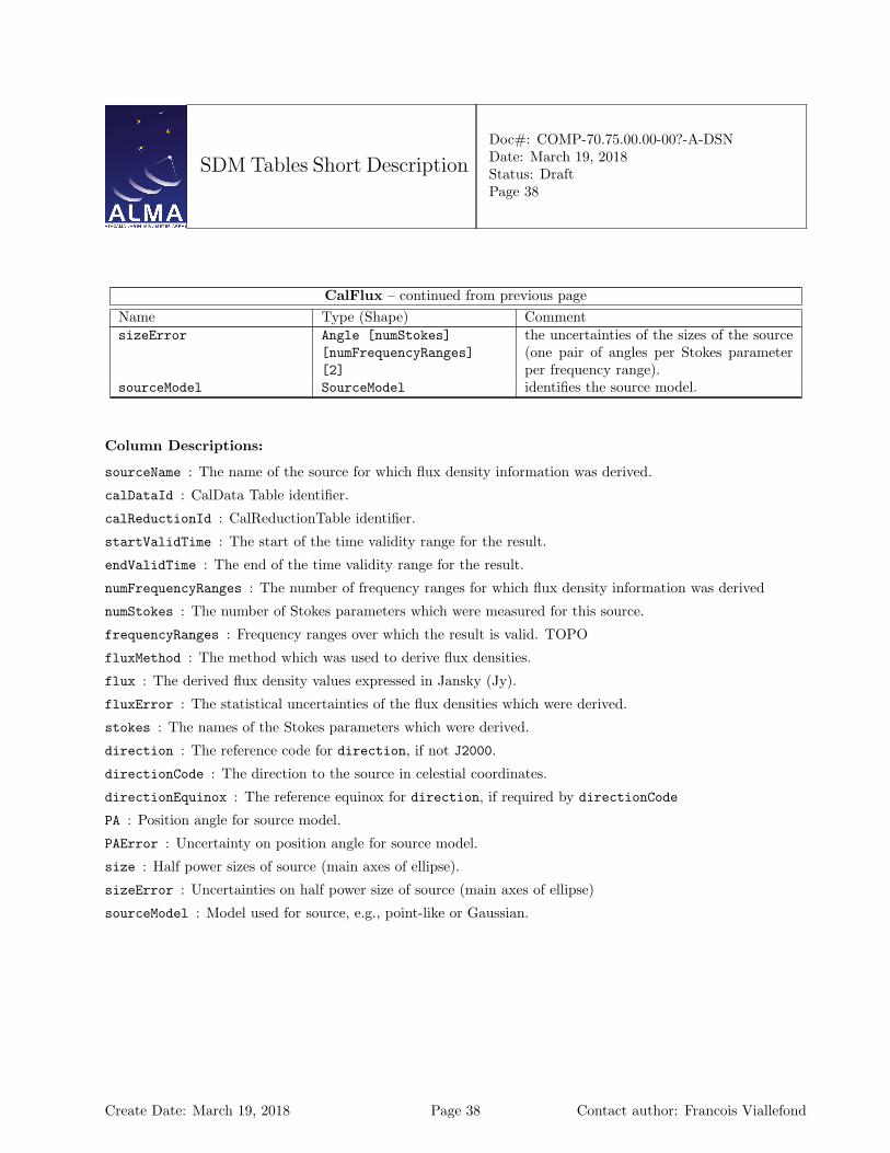
CalFlux – continued from previous pageName Type (Shape) CommentsizeError Angle [numStokes]
[numFrequencyRanges][2]
the uncertainties of the sizes of the source(one pair of angles per Stokes parameterper frequency range).
sourceModel SourceModel identifies the source model.
Column Descriptions:
sourceName : The name of the source for which flux density information was derived.
calDataId : CalData Table identifier.
calReductionId : CalReductionTable identifier.
startValidTime : The start of the time validity range for the result.
endValidTime : The end of the time validity range for the result.
numFrequencyRanges : The number of frequency ranges for which flux density information was derived
numStokes : The number of Stokes parameters which were measured for this source.
frequencyRanges : Frequency ranges over which the result is valid. TOPO
fluxMethod : The method which was used to derive flux densities.
flux : The derived flux density values expressed in Jansky (Jy).
fluxError : The statistical uncertainties of the flux densities which were derived.
stokes : The names of the Stokes parameters which were derived.
direction : The reference code for direction, if not J2000.
directionCode : The direction to the source in celestial coordinates.
directionEquinox : The reference equinox for direction, if required by directionCode
PA : Position angle for source model.
PAError : Uncertainty on position angle for source model.
size : Half power sizes of source (main axes of ellipse).
sizeError : Uncertainties on half power size of source (main axes of ellipse)
sourceModel : Model used for source, e.g., point-like or Gaussian.
Create Date: March 19, 2018 Page 38 Contact author: Francois Viallefond
SDM Tables Short Description
Doc#: COMP-70.75.00.00-00?-A-DSNDate: March 19, 2018Status: DraftPage 39
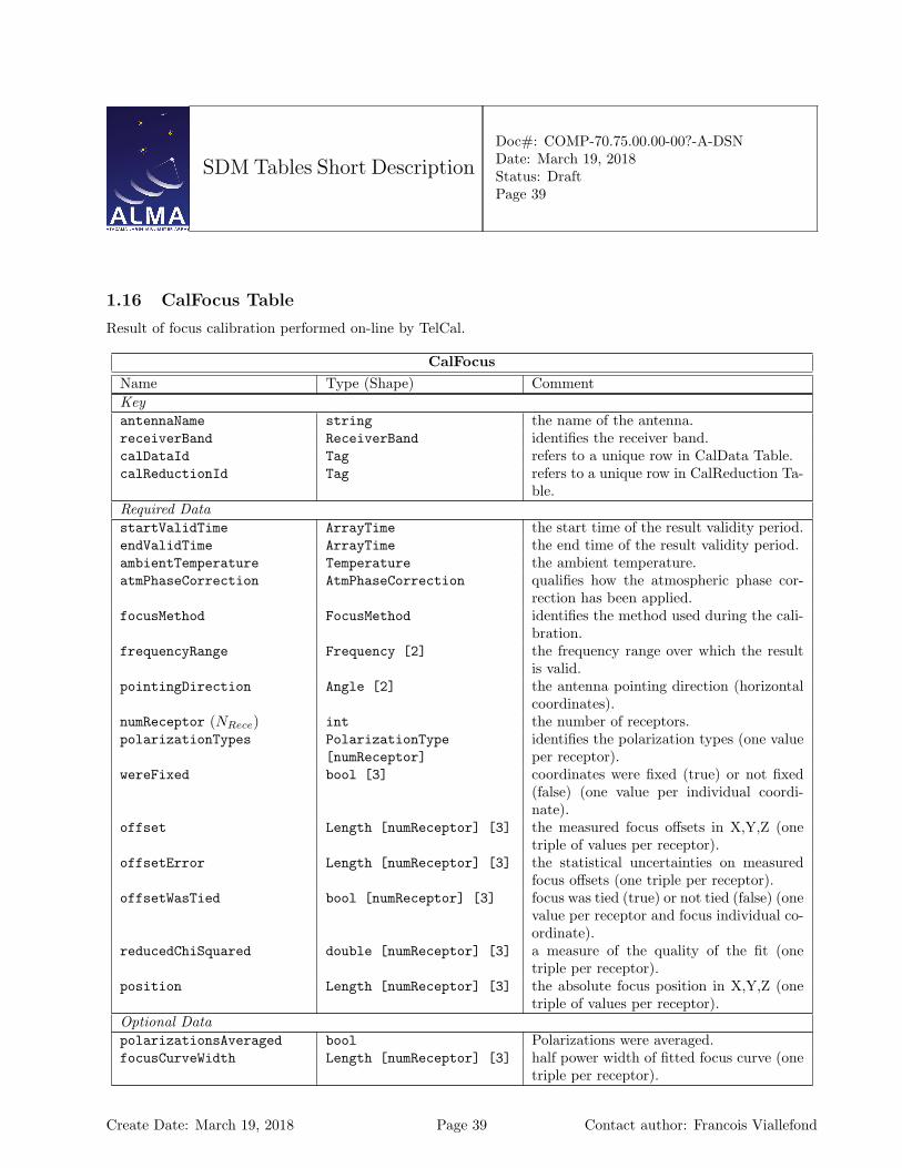
1.16 CalFocus Table
Result of focus calibration performed on-line by TelCal.
CalFocusName Type (Shape) CommentKeyantennaName string the name of the antenna.receiverBand ReceiverBand identifies the receiver band.calDataId Tag refers to a unique row in CalData Table.calReductionId Tag refers to a unique row in CalReduction Ta-
ble.Required DatastartValidTime ArrayTime the start time of the result validity period.endValidTime ArrayTime the end time of the result validity period.ambientTemperature Temperature the ambient temperature.atmPhaseCorrection AtmPhaseCorrection qualifies how the atmospheric phase cor-
rection has been applied.focusMethod FocusMethod identifies the method used during the cali-
bration.frequencyRange Frequency [2] the frequency range over which the result
is valid.pointingDirection Angle [2] the antenna pointing direction (horizontal
coordinates).numReceptor (NRece) int the number of receptors.polarizationTypes PolarizationType
[numReceptor]identifies the polarization types (one valueper receptor).
wereFixed bool [3] coordinates were fixed (true) or not fixed(false) (one value per individual coordi-nate).
offset Length [numReceptor] [3] the measured focus offsets in X,Y,Z (onetriple of values per receptor).
offsetError Length [numReceptor] [3] the statistical uncertainties on measuredfocus offsets (one triple per receptor).
offsetWasTied bool [numReceptor] [3] focus was tied (true) or not tied (false) (onevalue per receptor and focus individual co-ordinate).
reducedChiSquared double [numReceptor] [3] a measure of the quality of the fit (onetriple per receptor).
position Length [numReceptor] [3] the absolute focus position in X,Y,Z (onetriple of values per receptor).
Optional DatapolarizationsAveraged bool Polarizations were averaged.focusCurveWidth Length [numReceptor] [3] half power width of fitted focus curve (one
triple per receptor).
Create Date: March 19, 2018 Page 39 Contact author: Francois Viallefond
SDM Tables Short Description
Doc#: COMP-70.75.00.00-00?-A-DSNDate: March 19, 2018Status: DraftPage 40
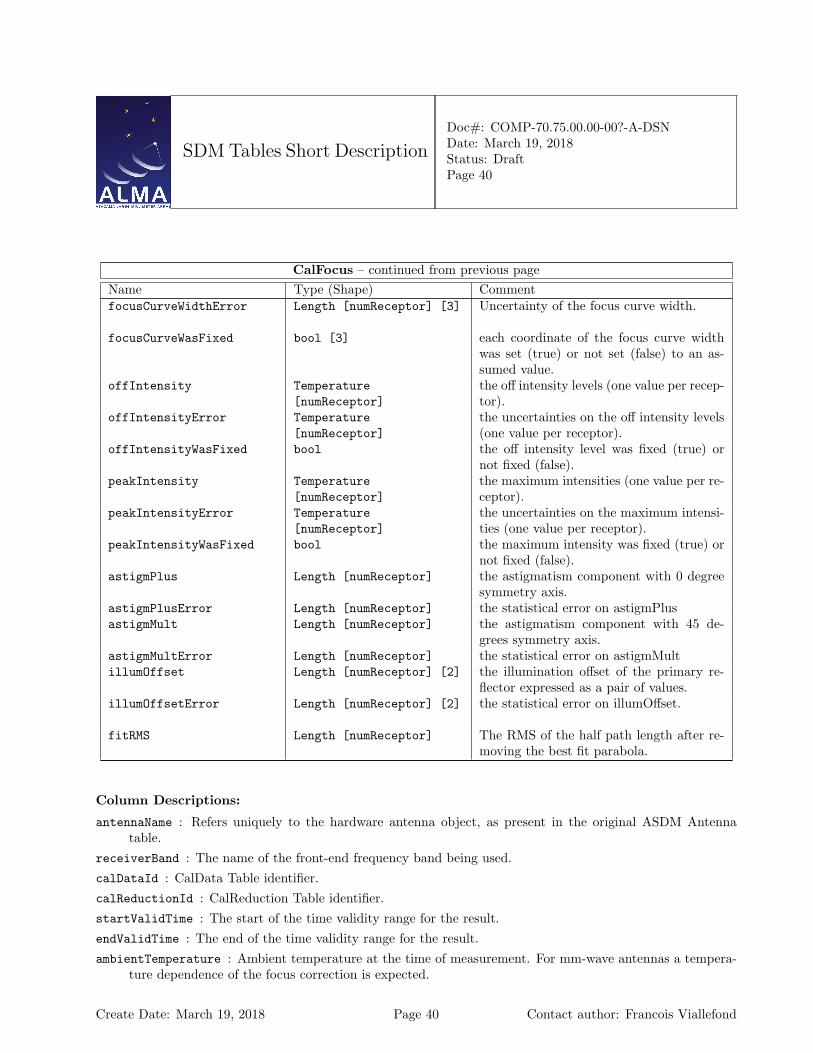
CalFocus – continued from previous pageName Type (Shape) CommentfocusCurveWidthError Length [numReceptor] [3] Uncertainty of the focus curve width.
focusCurveWasFixed bool [3] each coordinate of the focus curve widthwas set (true) or not set (false) to an as-sumed value.
offIntensity Temperature[numReceptor]
the off intensity levels (one value per recep-tor).
offIntensityError Temperature[numReceptor]
the uncertainties on the off intensity levels(one value per receptor).
offIntensityWasFixed bool the off intensity level was fixed (true) ornot fixed (false).
peakIntensity Temperature[numReceptor]
the maximum intensities (one value per re-ceptor).
peakIntensityError Temperature[numReceptor]
the uncertainties on the maximum intensi-ties (one value per receptor).
peakIntensityWasFixed bool the maximum intensity was fixed (true) ornot fixed (false).
astigmPlus Length [numReceptor] the astigmatism component with 0 degreesymmetry axis.
astigmPlusError Length [numReceptor] the statistical error on astigmPlusastigmMult Length [numReceptor] the astigmatism component with 45 de-
grees symmetry axis.astigmMultError Length [numReceptor] the statistical error on astigmMultillumOffset Length [numReceptor] [2] the illumination offset of the primary re-
flector expressed as a pair of values.illumOffsetError Length [numReceptor] [2] the statistical error on illumOffset.
fitRMS Length [numReceptor] The RMS of the half path length after re-moving the best fit parabola.
Column Descriptions:
antennaName : Refers uniquely to the hardware antenna object, as present in the original ASDM Antennatable.
receiverBand : The name of the front-end frequency band being used.calDataId : CalData Table identifier.calReductionId : CalReduction Table identifier.startValidTime : The start of the time validity range for the result.endValidTime : The end of the time validity range for the result.ambientTemperature : Ambient temperature at the time of measurement. For mm-wave antennas a tempera-
ture dependence of the focus correction is expected.
Create Date: March 19, 2018 Page 40 Contact author: Francois Viallefond

SDM Tables Short Description
Doc#: COMP-70.75.00.00-00?-A-DSNDate: March 19, 2018Status: DraftPage 41
atmPhaseCorrection : The atmospheric phase correction states for which result is given.
focusMethod : Method used, e.g., ’Interferometry’ or ’5 points’
frequencyRange : Frequency range over which the result is valid. TOPO
pointingDirection : The antenna pointing direction (horizontal coordinates). For mm-wave antennas anelevation dependence of the focus correction is expected. AZELNOWAntenna.position
numReceptor : Number of receptors.
polarizationTypes : The relevant polarizations for the measured focus parameters.
wereFixed : Indicates which focus coordinates were kept fixed during measursment (and thus were not mea-sured).
offset : The measured focus offsets in X, Y, Z. This offset is relative to the nominal position of the focus,once the focus model has been applied.
offsetError : Uncertainty of offset.
offsetWasTied : True for a polarization and focus coordinate when this quantity was assumed fixed relativeto the corresponding coordinate in the other polarization.
reducedChiSquared : Reduced χ2 indicating the quality of the least-squares fit.
position : long doc missing
polarizationsAveraged : Set when polarizations were averaged over to improve sensitivity.
focusCurveWidth : Half-power width of fitted focus curve.
focusCurveWidthError : Statistical uncertainty of the half-power width of the fitted focus curve.
focusCurveWasFixed : Indicates that the half-power width of the fitted focus curvewas fixed to an assumedvalue.
offIntensity : Off intensity level. This is needed for completeness to define the fitted beam function wheneverthe off level is non-zero (single-dish pointing).
offIntensityError : Off intensity level uncertainty
offIntensityWasFixed : Off intensity level was fixed.
peakIntensity : Fitted maximum intensity of signal.
peakIntensityError : Statistical uncertainty of the fitted maximum signal intensity.
peakIntensityWasFixed : Indicates that the maximal signal intensity was fixed to an assumed value.
astigmPlus : long doc missing
astigmPlusError : long doc missing
astigmMult : long doc missing
astigmMultError : long doc missing
illumOffset : long doc missing
illumOffsetError : long doc missing
fitRMS : long doc missing
Create Date: March 19, 2018 Page 41 Contact author: Francois Viallefond

SDM Tables Short Description
Doc#: COMP-70.75.00.00-00?-A-DSNDate: March 19, 2018Status: DraftPage 42
1.17 CalFocusModel Table
Result of focus model calibration performed by TelCal.
CalFocusModelName Type (Shape) CommentKeyantennaName string the name of the antenna.receiverBand ReceiverBand identifies the receiver band.polarizationType PolarizationType identifies the polarization type for which
this focus model is valid.calDataId Tag refers to a unique row in CalData Table.calReductionId Tag refers to a unique row in CalReduction Ta-
ble.Required DatastartValidTime ArrayTime the start time of result validity period.endValidTime ArrayTime the end time of result validity period.antennaMake AntennaMake identifies the antenna make.numCoeff (NCoef ) int the number of coefficients.numSourceObs (NSour) int the number of source directions observed
to derive the model.coeffName string [numCoeff] the names given to the coefficients in the
model.coeffFormula string [numCoeff] the coefficients formula (one string per co-
efficient).coeffValue float [numCoeff] the fitted values of the coefficients.coeffError float [numCoeff] the statistical uncertainties on the derived
coefficients (one value per coefficient).coeffFixed bool [numCoeff] one coefficient was fixed (true) or not fixed
(false) (one boolean value per coefficient).focusModel string the name of this focus model.focusRMS Length [3] the RMS deviations of residuals of focus
coordinates.reducedChiSquared double a measure of the quality of the least-square
fit.
Column Descriptions:
antennaName : Refers uniquely to the hardware antenna object, as present in the original ASDM Antennatable.
receiverBand : The name of the front-end frequency band being used.
polarizationType : Polarization component for which the focus model is valid.
calDataId : CalData Table identifier.
Create Date: March 19, 2018 Page 42 Contact author: Francois Viallefond
SDM Tables Short Description
Doc#: COMP-70.75.00.00-00?-A-DSNDate: March 19, 2018Status: DraftPage 43
calReductionId : CalReduction Table identifier.
startValidTime : The start of the time validity range for the result.
endValidTime : The end of the time validity range for the result.
antennaMake : The antenna make (e.g., for ALMA, the manufacturer name such as AEC, Vertex, or Melco).
numCoeff : Number of coefficients in the focus model.
numSourceObs : Number of source directions observed to derive the model.
coeffName : The given names of the coefficients in the model.
coeffFormula : The formula describing the fitted functional dependence for the focus coordinate.
coeffValue : The fitted value for the coefficient.
coeffError : The statistical uncertainty on the derived coefficients.
coeffFixed : A boolean specifying that the coefficient was fixed to an assumed value.
focusModel : Name of this focus model.
focusRMS : The root mean square deviation of residuals in focus coordinates.
reducedChiSquared : Reduced χ2 indicating the quality of the least-squares fit.
Create Date: March 19, 2018 Page 43 Contact author: Francois Viallefond
SDM Tables Short Description
Doc#: COMP-70.75.00.00-00?-A-DSNDate: March 19, 2018Status: DraftPage 44
1.18 CalGain Table
This Table is a placeholder to be used to wrap up casa gain tables produced in the Science Pipeline and Offlineso that they can be archived in the ALMA Calibration Data Base.
CalGainName Type (Shape) CommentKeycalDataId Tag refers to a unique row in CalData Table.calReductionId Tag refers to a unique row in CalReduc-
tionTable.Required DatastartValidTime ArrayTime the start time of result validity period.endValidTime ArrayTime the end time of result validity period.gain float TBDgainValid bool TBDfit float TBDfitWeight float TBDtotalGainValid bool TBDtotalFit float TBDtotalFitWeight float TBD
Column Descriptions:
calDataId : CalData Table identifier.
calReductionId : CalReduction Table identifier.
startValidTime : The start of the time validity range for the result.
endValidTime : The end of the time validity range for the result.
gain : TBD
gainValid : TBD
fit : TBD
fitWeight : TBD
totalGainValid : TBD
totalFit : TBD
totalFitWeight : TBD
Create Date: March 19, 2018 Page 44 Contact author: Francois Viallefond
SDM Tables Short Description
Doc#: COMP-70.75.00.00-00?-A-DSNDate: March 19, 2018Status: DraftPage 45
1.19 CalHolography Table
Result of holography calibration performed by TelCal.
CalHolographyName Type (Shape) CommentKeyantennaName string the name of the antenna.calDataId Tag refers to a unique row in CalData Table.calReductionId Tag refers to a unique row in CalReduction Ta-
ble.Required DataantennaMake AntennaMake identifies the antenna make.startValidTime ArrayTime Start time of result validity periodendValidTime ArrayTime the end time of result validity period.ambientTemperature Temperature the ambient temperature.focusPosition Length [3] the focus position.frequencyRange Frequency [2] the range of frequencies for which the mea-
surement is valid.illuminationTaper double the amplitude illumination taper.numReceptor (NRece) int the number of receptors.polarizationTypes PolarizationType
[numReceptor]identifies the polarization types (one valueper receptor).
numPanelModes (NPane) int the number panel modes fitted.receiverBand ReceiverBand identifies the receiver band.beamMapUID EntityRef refers to the beam map image.rawRMS Length the RMS of the pathlength residuals.weightedRMS Length the weigthted RMS of the pathlength resid-
uals.surfaceMapUID EntityRef refers to the resulting antenna surface map
image.direction Angle [2] the direction of the source.Optional DatanumScrew (NScre) int the number of screws.screwName string [numScrew] the names of the screws (one value per
screw).screwMotion Length [numScrew] the prescribed screw motions (one value
per screw).screwMotionError Length [numScrew] the uncertainties on the prescribed screw
motions (one value per screw).gravCorrection bool indicates if a gravitational correction was
applied (true) or not (false).gravOptRange Angle [2] the range of gravitational optimization.tempCorrection bool indicates if a temperature correction was
applied (true) or not (false).
Create Date: March 19, 2018 Page 45 Contact author: Francois Viallefond
SDM Tables Short Description
Doc#: COMP-70.75.00.00-00?-A-DSNDate: March 19, 2018Status: DraftPage 46
CalHolography – continued from previous pageName Type (Shape) CommenttempOptRange Temperature [2] the range of temperature optimization.
Column Descriptions:
antennaName : Refers uniquely to the hardware antenna object, as present in the original ASDM Antennatable.
calDataId : CalData Table identifier.
calReductionId : CalReduction Table identifier.
antennaMake : The antenna make (e.g., for ALMA, the manufacturer name such as AEC, Vertex, or Melco).
startValidTime : The start of the time validity range for the result.
endValidTime : The end of the time validity range for the result.
ambientTemperature : Ambient temperature at the time of measurement. The surface deformations areexpected to depend on temperature.
focusPosition : The optimal focus position (in XYZ) as derived from the aperture map phases. REFLECTOR
frequencyRange : Frequency range over which the result is valid. TOPO
illuminationTaper : Power illumination taper assumed to calculate weighted rms.
numReceptor : The number or polarization receptors (one or two) for which the result is given.
polarizationTypes : The polarization types of the receptors being used.
numPanelModes : The number of panel independent position/deformation modes that have been fitted.
receiverBand : The name of the front-end frequency band being used.
beamMapUID : The beam map UID provides a link to the resulting beam map image either as a disk file or inthe ALMA Archive. The disk file name is built from the UID string by replacing all colons and slashesby underscores.
rawRMS : The root mean square of the pathlength residuals, measured along Z, that is perpendicular to theaperture plane when looking a source at infinite distance.
weightedRMS : The root mean square of pathlength residuals (along Z); weighted assuming a primary beamillumination as specified by illuminationTaper.
surfaceMapUID : The surface map UID provides a link to the resulting antenna surface map image either as adisk file or in the ALMA Archive. The disk file name is built from the UID string by replacing all colonsand slashes by underscores.
direction : The antenna pointing direction (horizontal coordinates) AZELNOWAntenna..position
numScrew : Number of screws to be adjusted using surface map data.
screwName : The string identification of the panel screws.
screwMotion : The prescribed panel screw adjustments derived from the panel fit to the aperture map phases.
Create Date: March 19, 2018 Page 46 Contact author: Francois Viallefond
SDM Tables Short Description
Doc#: COMP-70.75.00.00-00?-A-DSNDate: March 19, 2018Status: DraftPage 47
screwMotionError : The statistical uncertainties on the prescribed panel screw adjustments derived from thepanel fit to the aperture map phases.
gravCorrection : Optimization target elevation range for the gravitaionnal correction applied.
gravOptRange : Optimization target elevation range for the gravitaionnal correction applied.
tempCorrection : A temperature correction was applied in the screw motion data.
tempOptRange : Optimization target temperature range.
Create Date: March 19, 2018 Page 47 Contact author: Francois Viallefond
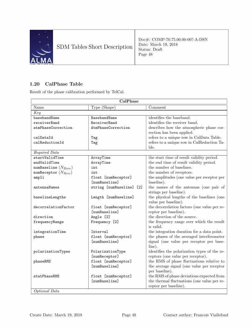
SDM Tables Short Description
Doc#: COMP-70.75.00.00-00?-A-DSNDate: March 19, 2018Status: DraftPage 48
1.20 CalPhase Table
Result of the phase calibration performed by TelCal.
CalPhaseName Type (Shape) CommentKeybasebandName BasebandName identifies the baseband.receiverBand ReceiverBand identifies the receiver band.atmPhaseCorrection AtmPhaseCorrection describes how the atmospheric phase cor-
rection has been applied.calDataId Tag refers to a unique row in CalData Table.calReductionId Tag refers to a unique row in CalReduction Ta-
ble.Required DatastartValidTime ArrayTime the start time of result validity period.endValidTime ArrayTime the end time of result validity period.numBaseline (NBase) int the number of baselines.numReceptor (NRece) int the number of receptors.ampli float [numReceptor]
[numBaseline]the amplitudes (one value per receptor perbaseline).
antennaNames string [numBaseline] [2] the names of the antennas (one pair ofstrings per baseline).
baselineLengths Length [numBaseline] the physical lengths of the baselines (onevalue per baseline).
decorrelationFactor float [numReceptor][numBaseline]
the decorrelation factors (one value per re-ceptor per baseline).
direction Angle [2] the direction of the source.frequencyRange Frequency [2] the frequency range over which the result
is valid.integrationTime Interval the integration duration for a data point.phase float [numReceptor]
[numBaseline]the phases of the averaged interferometersignal (one value per receptor per base-line).
polarizationTypes PolarizationType[numReceptor]
identifies the polarization types of the re-ceptors (one value per receptor).
phaseRMS float [numReceptor][numBaseline]
the RMS of phase fluctuations relative tothe average signal (one value per receptorper baseline).
statPhaseRMS float [numReceptor][numBaseline]
the RMS of phase deviations expected fromthe thermal fluctuations (one value per re-ceptor per baseline).
Optional Data
Create Date: March 19, 2018 Page 48 Contact author: Francois Viallefond
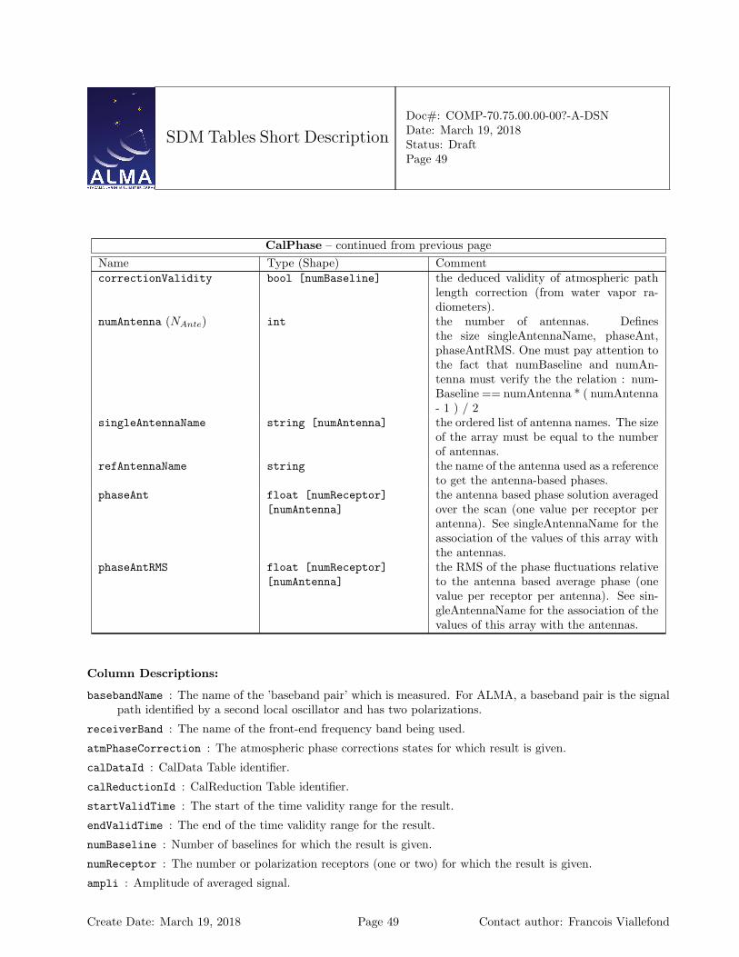
SDM Tables Short Description
Doc#: COMP-70.75.00.00-00?-A-DSNDate: March 19, 2018Status: DraftPage 49
CalPhase – continued from previous pageName Type (Shape) CommentcorrectionValidity bool [numBaseline] the deduced validity of atmospheric path
length correction (from water vapor ra-diometers).
numAntenna (NAnte) int the number of antennas. Definesthe size singleAntennaName, phaseAnt,phaseAntRMS. One must pay attention tothe fact that numBaseline and numAn-tenna must verify the the relation : num-Baseline == numAntenna * ( numAntenna- 1 ) / 2
singleAntennaName string [numAntenna] the ordered list of antenna names. The sizeof the array must be equal to the numberof antennas.
refAntennaName string the name of the antenna used as a referenceto get the antenna-based phases.
phaseAnt float [numReceptor][numAntenna]
the antenna based phase solution averagedover the scan (one value per receptor perantenna). See singleAntennaName for theassociation of the values of this array withthe antennas.
phaseAntRMS float [numReceptor][numAntenna]
the RMS of the phase fluctuations relativeto the antenna based average phase (onevalue per receptor per antenna). See sin-gleAntennaName for the association of thevalues of this array with the antennas.
Column Descriptions:
basebandName : The name of the ’baseband pair’ which is measured. For ALMA, a baseband pair is the signalpath identified by a second local oscillator and has two polarizations.
receiverBand : The name of the front-end frequency band being used.
atmPhaseCorrection : The atmospheric phase corrections states for which result is given.
calDataId : CalData Table identifier.
calReductionId : CalReduction Table identifier.
startValidTime : The start of the time validity range for the result.
endValidTime : The end of the time validity range for the result.
numBaseline : Number of baselines for which the result is given.
numReceptor : The number or polarization receptors (one or two) for which the result is given.
ampli : Amplitude of averaged signal.
Create Date: March 19, 2018 Page 49 Contact author: Francois Viallefond
SDM Tables Short Description
Doc#: COMP-70.75.00.00-00?-A-DSNDate: March 19, 2018Status: DraftPage 50
antennaNames : Refer uniquely to the hardware antenna object, as present in the original ASDM Antennatable.
baselineLengths : The physical length of each baseline.
decorrelationFactor : The calculated decorrelation factor (amplitude loss) due to non-thermal phase fluctu-ations.
direction : The antenna pointing direction in horizontal coordinates. AZELNOWAntenna.position
frequencyRange : Frequency range over which the result is valid TOPO
integrationTime : Integration time on a data point, to calculate rms.
phase : The phase of the averaged interferometer signal.
polarizationTypes : The polarization types of the receptors being used.
phaseRMS : The root mean square of phase fluctuations relative to the average signal.
statPhaseRMS : The root mean square of phase deviations expected from thermal fluctuations.
correctionValidity : Deduced validity of atmospheric path length correction (from Water Vapour Radiome-ters; remark: It is not clear that correctionValidity is really an array. What about its size?).
numAntenna : long doc missing
singleAntennaName : long doc missing
refAntennaName : long doc missing
phaseAnt : long doc missing
phaseAntRMS : long doc missing
Create Date: March 19, 2018 Page 50 Contact author: Francois Viallefond
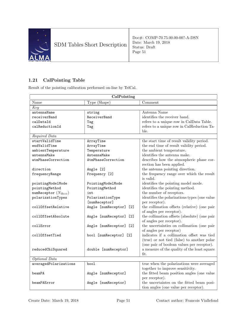
SDM Tables Short Description
Doc#: COMP-70.75.00.00-00?-A-DSNDate: March 19, 2018Status: DraftPage 51
1.21 CalPointing Table
Result of the pointing calibration performed on-line by TelCal.
CalPointingName Type (Shape) CommentKeyantennaName string Antenna NamereceiverBand ReceiverBand identifies the receiver band.calDataId Tag refers to a unique row in CalData Table.calReductionId Tag refers to a unique row in CalReduction Ta-
ble.Required DatastartValidTime ArrayTime the start time of result validity period.endValidTime ArrayTime the end time of result validity period.ambientTemperature Temperature the ambient temperature.antennaMake AntennaMake identifies the antenna make.atmPhaseCorrection AtmPhaseCorrection describes how the atmospheric phase cor-
rection has been applied.direction Angle [2] the antenna pointing direction.frequencyRange Frequency [2] the frequency range over which the result
is valid.pointingModelMode PointingModelMode identifies the pointing model mode.pointingMethod PointingMethod identifies the pointing method.numReceptor (NRece) int the number of receptors.polarizationTypes PolarizationType
[numReceptor]identifies the polarizations types (one valueper receptor).
collOffsetRelative Angle [numReceptor] [2] the collimation offsets (relative) (one pairof angles per receptor).
collOffsetAbsolute Angle [numReceptor] [2] the collimation offsets (absolute) (one pairof angles per receptor).
collError Angle [numReceptor] [2] the uncertainties on collimation (one pairof angles per receptor)
collOffsetTied bool [numReceptor] [2] indicates if a collimation offset was tied(true) or not tied (false) to another polar(one pair of boolean values per receptor).
reducedChiSquared double [numReceptor] a measure of the quality of the least squarefit.
Optional DataaveragedPolarizations bool true when the polarizations were averaged
together to improve sensitivity.beamPA Angle [numReceptor] the fitted beam position angles (one value
per receptor).beamPAError Angle [numReceptor] the uncertaintes on the fitted beam posi-
tion angles (one value per receptor).
Create Date: March 19, 2018 Page 51 Contact author: Francois Viallefond
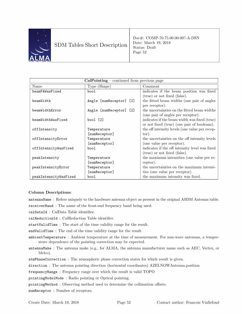
SDM Tables Short Description
Doc#: COMP-70.75.00.00-00?-A-DSNDate: March 19, 2018Status: DraftPage 52
CalPointing – continued from previous pageName Type (Shape) CommentbeamPAWasFixed bool indicates if the beam position was fixed
(true) or not fixed (false).beamWidth Angle [numReceptor] [2] the fitted beam widths (one pair of angles
per receptor).beamWidthError Angle [numReceptor] [2] the uncertainties on the fitted beam widths
(one pair of angles per receptor).beamWidthWasFixed bool [2] indicates if the beam width was fixed (true)
or not fixed (true) (one pair of booleans).offIntensity Temperature
[numReceptor]the off intensity levels (one value per recep-tor).
offIntensityError Temperature[numReceptor]
the uncertainties on the off intensity levels(one value per receptor).
offIntensityWasFixed bool indicates if the off intensity level was fixed(true) or not fixed (false).
peakIntensity Temperature[numReceptor]
the maximum intensities (one value per re-ceptor).
peakIntensityError Temperature[numReceptor]
the uncertainties on the maximum intensi-ties (one value per receptor).
peakIntensityWasFixed bool the maximum intensity was fixed.
Column Descriptions:
antennaName : Refers uniquely to the hardware antenna object as present in the original ASDM Antenna table.
receiverBand : The name of the front-end frequency band being used.
calDataId : CalData Table identifier.
calReductionId : CalReduction Table identifier.
startValidTime : The start of the time validity range for the result.
endValidTime : The end of the time validity range for the result.
ambientTemperature : Ambient temperature at the time of measurement. For mm-wave antennas, a temper-ature dependence of the pointing correction may be expected.
antennaMake : The antenna make (e.g., for ALMA, the antenna manufacturer name such as AEC, Vertex, orMelco).
atmPhaseCorrection : The atmospheric phase correction states for which result is given.
direction : The antenna pointing direction (horizontal coordinates) AZELNOWAntenna.position
frequencyRange : Frequency range over which the result is valid TOPO
pointingModelMode : Radio pointing or Optical pointing.
pointingMethod : Observing method used to determine the collimation offsets.
numReceptor : Number of receptors.
Create Date: March 19, 2018 Page 52 Contact author: Francois Viallefond

SDM Tables Short Description
Doc#: COMP-70.75.00.00-00?-A-DSNDate: March 19, 2018Status: DraftPage 53
polarizationTypes : The relevant polarizations for the measured pointing parameters.
collOffsetRelative : The collimation offsets found required to center the source, relative to the expected di-rection of the source, using a predetermined pointing model. These are the collimation offsets to be appliedfor reference pointing, or for a more refined local pointing model. AZELNOWAntenna.position[virtual]
collOffsetAbsolute : The collimation offsets found required to center the source, relative to the expecteddirection of the source assuming a perfect antenna mount. These are collimation offsets to be used fordetermination of the pointing model. AZELNOWAntenna.positiontarget
collError : Statistical uncertainties in the determination of azimuth and elevation collimations.
collOffsetTied : True for a polarization coordinate when this quantity was assumed fixed relative to thecorresponding coordinate in the other polarization.
reducedChiSquared : Reduced χ2 indicating the quality of the least-squares fit.
averagedPolarizations : Set when polarizations were averaged together to improve sensitivity.
beamPA : Position angle of fitted antenna beam.
beamPAError : Statistical uncertainty of position angle of fitted antenna beam.
beamPAWasFixed : Indicates that the position angle of the fitted antenna beam was fixed to an assumed value.
beamWidth : Half-power width of fitted antenna beam.
beamWidthError : Statistical uncertainty of the half-power width of the fitted antenna beam.
beamWidthWasFixed : Indicates that the half-power width of antenna beam was fixed to an assumed value.
offIntensity : Off intensity level. This is needed for completeness to define the fitted beam function wheneverthe off level is non-zero (single-dish pointing).
offIntensityError : Off intensity level uncertainty.
offIntensityWasFixed : Off intensity level was fixed.
peakIntensity : Fitted maximum intensity of signal.
peakIntensityError : Statistical uncertainty of the fitted maximum signal intensity.
peakIntensityWasFixed : Indicates that the maximal signal intensity was fixed to an assumed value.
Create Date: March 19, 2018 Page 53 Contact author: Francois Viallefond
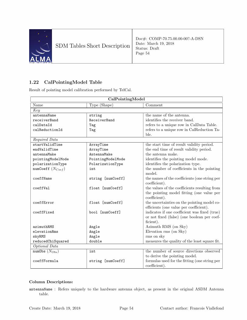
SDM Tables Short Description
Doc#: COMP-70.75.00.00-00?-A-DSNDate: March 19, 2018Status: DraftPage 54
1.22 CalPointingModel Table
Result of pointing model calibration performed by TelCal.
CalPointingModelName Type (Shape) CommentKeyantennaName string the name of the antenna.receiverBand ReceiverBand identifies the receiver band.calDataId Tag refers to a unique row in CalData Table.calReductionId Tag refers to a unique row in CalReduction Ta-
ble.Required DatastartValidTime ArrayTime the start time of result validity period.endValidTime ArrayTime the end time of result validity period.antennaMake AntennaMake the antenna make.pointingModelMode PointingModelMode identifies the pointing model mode.polarizationType PolarizationType identifies the polarization type.numCoeff (NCoef ) int the number of coefficients in the pointing
model.coeffName string [numCoeff] the names of the coefficients (one string per
coefficient).coeffVal float [numCoeff] the values of the coefficients resulting from
the pointing model fitting (one value percoefficient).
coeffError float [numCoeff] the uncertainties on the pointing model co-efficients (one value per coefficient).
coeffFixed bool [numCoeff] indicates if one coefficient was fixed (true)or not fixed (false) (one boolean per coef-ficient).
azimuthRMS Angle Azimuth RMS (on Sky)elevationRms Angle Elevation rms (on Sky)skyRMS Angle rms on skyreducedChiSquared double measures the quality of the least square fit.Optional DatanumObs (NObs) int the number of source directions observed
to derive the pointing model.coeffFormula string [numCoeff] formulas used for the fitting (one string per
coefficient).
Column Descriptions:
antennaName : Refers uniquely to the hardware antenna object, as present in the original ASDM Antennatable.
Create Date: March 19, 2018 Page 54 Contact author: Francois Viallefond
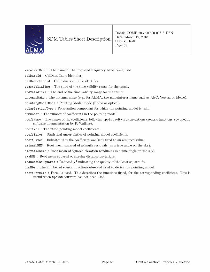
SDM Tables Short Description
Doc#: COMP-70.75.00.00-00?-A-DSNDate: March 19, 2018Status: DraftPage 55
receiverBand : The name of the front-end frequency band being used.
calDataId : CalData Table identifier.
calReductionId : CalReduction Table identifier.
startValidTime : The start of the time validity range for the result.
endValidTime : The end of the time validity range for the result.
antennaMake : The antenna make (e.g., for ALMA, the manufaturer name such as AEC, Vertex, or Melco).
pointingModelMode : Pointing Model mode (Radio or optical)
polarizationType : Polarization component for which the pointing model is valid.
numCoeff : The number of coefficients in the pointing model.
coeffName : The names of the coefficients, following tpoint software conventions (generic functions, see tpointsoftware documentation by P. Wallace).
coeffVal : The fitted pointing model coefficients.
coeffError : Statistical uncertainties of pointing model coefficients.
coeffFixed : Indicates that the coefficient was kept fixed to an assumed value.
azimuthRMS : Root mean squared of azimuth residuals (as a true angle on the sky).
elevationRms : Root mean of squared elevation residuals (as a true angle on the sky).
skyRMS : Root mean squared of angular distance deviations.
reducedChiSquared : Reduced χ2 indicating the quality of the least-squares fit.
numObs : The number of source directions observed used to derive the pointing model.
coeffFormula : Formula used. This describes the functions fitted, for the corresponding coefficient. This isuseful when tpoint software has not been used.
Create Date: March 19, 2018 Page 55 Contact author: Francois Viallefond
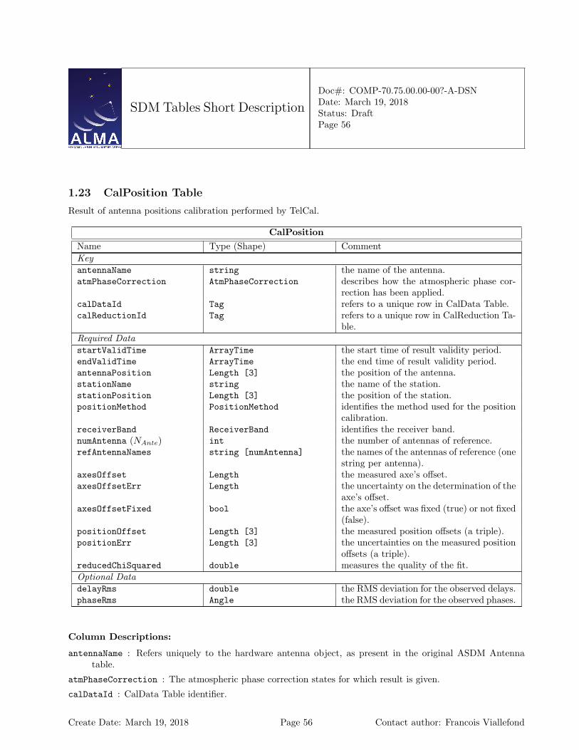
SDM Tables Short Description
Doc#: COMP-70.75.00.00-00?-A-DSNDate: March 19, 2018Status: DraftPage 56
1.23 CalPosition Table
Result of antenna positions calibration performed by TelCal.
CalPositionName Type (Shape) CommentKeyantennaName string the name of the antenna.atmPhaseCorrection AtmPhaseCorrection describes how the atmospheric phase cor-
rection has been applied.calDataId Tag refers to a unique row in CalData Table.calReductionId Tag refers to a unique row in CalReduction Ta-
ble.Required DatastartValidTime ArrayTime the start time of result validity period.endValidTime ArrayTime the end time of result validity period.antennaPosition Length [3] the position of the antenna.stationName string the name of the station.stationPosition Length [3] the position of the station.positionMethod PositionMethod identifies the method used for the position
calibration.receiverBand ReceiverBand identifies the receiver band.numAntenna (NAnte) int the number of antennas of reference.refAntennaNames string [numAntenna] the names of the antennas of reference (one
string per antenna).axesOffset Length the measured axe’s offset.axesOffsetErr Length the uncertainty on the determination of the
axe’s offset.axesOffsetFixed bool the axe’s offset was fixed (true) or not fixed
(false).positionOffset Length [3] the measured position offsets (a triple).positionErr Length [3] the uncertainties on the measured position
offsets (a triple).reducedChiSquared double measures the quality of the fit.Optional DatadelayRms double the RMS deviation for the observed delays.phaseRms Angle the RMS deviation for the observed phases.
Column Descriptions:
antennaName : Refers uniquely to the hardware antenna object, as present in the original ASDM Antennatable.
atmPhaseCorrection : The atmospheric phase correction states for which result is given.
calDataId : CalData Table identifier.
Create Date: March 19, 2018 Page 56 Contact author: Francois Viallefond
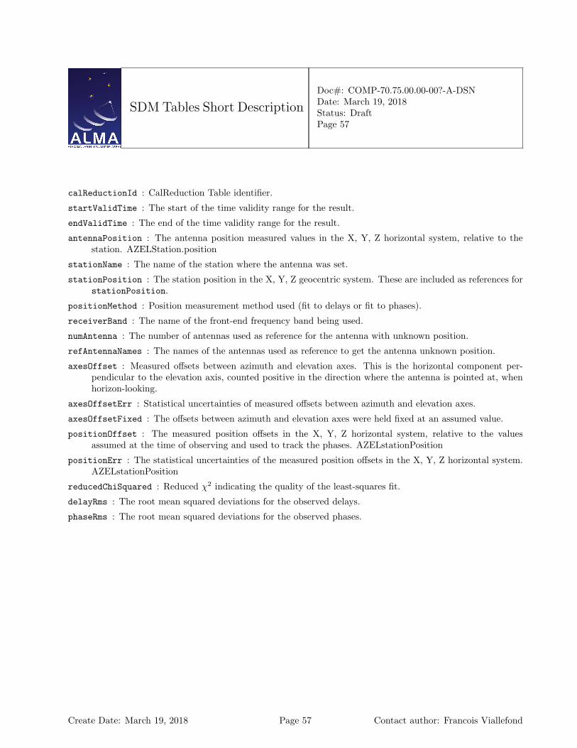
SDM Tables Short Description
Doc#: COMP-70.75.00.00-00?-A-DSNDate: March 19, 2018Status: DraftPage 57
calReductionId : CalReduction Table identifier.
startValidTime : The start of the time validity range for the result.
endValidTime : The end of the time validity range for the result.
antennaPosition : The antenna position measured values in the X, Y, Z horizontal system, relative to thestation. AZELStation.position
stationName : The name of the station where the antenna was set.
stationPosition : The station position in the X, Y, Z geocentric system. These are included as references forstationPosition.
positionMethod : Position measurement method used (fit to delays or fit to phases).
receiverBand : The name of the front-end frequency band being used.
numAntenna : The number of antennas used as reference for the antenna with unknown position.
refAntennaNames : The names of the antennas used as reference to get the antenna unknown position.
axesOffset : Measured offsets between azimuth and elevation axes. This is the horizontal component per-pendicular to the elevation axis, counted positive in the direction where the antenna is pointed at, whenhorizon-looking.
axesOffsetErr : Statistical uncertainties of measured offsets between azimuth and elevation axes.
axesOffsetFixed : The offsets between azimuth and elevation axes were held fixed at an assumed value.
positionOffset : The measured position offsets in the X, Y, Z horizontal system, relative to the valuesassumed at the time of observing and used to track the phases. AZELstationPosition
positionErr : The statistical uncertainties of the measured position offsets in the X, Y, Z horizontal system.AZELstationPosition
reducedChiSquared : Reduced χ2 indicating the quality of the least-squares fit.
delayRms : The root mean squared deviations for the observed delays.
phaseRms : The root mean squared deviations for the observed phases.
Create Date: March 19, 2018 Page 57 Contact author: Francois Viallefond

SDM Tables Short Description
Doc#: COMP-70.75.00.00-00?-A-DSNDate: March 19, 2018Status: DraftPage 58
1.24 CalPrimaryBeam Table
Result of Primary Beam Map measurement.
CalPrimaryBeamName Type (Shape) CommentKeyantennaName string the name of the antenna.receiverBand ReceiverBand identifies the receiver band.calDataId Tag refers to a unique row in CalData Table.calReductionId Tag refers to a unique row in CalReduction Ta-
ble.Required DatastartValidTime ArrayTime the start time of result validity period.endValidTime ArrayTime the end time of result validity period.antennaMake AntennaMake the antenna make.numSubband (NSubb) int the number of subband images (frequency
ranges simultaneously measured ).frequencyRange Frequency [numSubband]
[2]the range of frequencies over which the re-sult is valid.
numReceptor (NRece) int the number of receptors.polarizationTypes PolarizationType
[numReceptor]identifies the polarizations types of the re-ceptors (one value per receptor).
mainBeamEfficiency double [numReceptor] the main beam efficiency as derived fromthe beam map.
beamDescriptionUID EntityRef refers to the beam description image.relativeAmplitudeRms float the RMS fluctuations in terms of the rela-
tive beam amplitude.direction Angle [2] the center direction.minValidDirection Angle [2] the minimum center direction of validity.maxValidDirection Angle [2] the maximum center direction of validity.descriptionType PrimaryBeamDescription quantity used to describe beam.imageChannelNumber int [numSubband] channel number in image for each subband.imageNominalFrequency Frequency [numSubband] nominal frequency for subband.
Column Descriptions:
antennaName : Refers uniquely to the hardware antenna object, as present in the original ASDM Antennatable.
receiverBand : The name of the front-end frequency band being used.
calDataId : CalData Table identifier.
calReductionId : CalReduction Table identifier.
startValidTime : The start of the time validity range for the result.
Create Date: March 19, 2018 Page 58 Contact author: Francois Viallefond
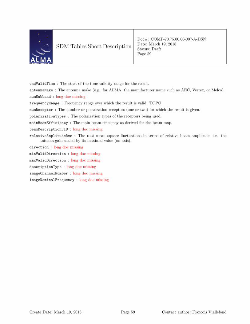
SDM Tables Short Description
Doc#: COMP-70.75.00.00-00?-A-DSNDate: March 19, 2018Status: DraftPage 59
endValidTime : The start of the time validity range for the result.
antennaMake : The antenna make (e.g., for ALMA, the manufacturer name such as AEC, Vertex, or Melco).
numSubband : long doc missing
frequencyRange : Frequency range over which the result is valid. TOPO
numReceptor : The number or polarization receptors (one or two) for which the result is given.
polarizationTypes : The polarization types of the receptors being used.
mainBeamEfficiency : The main beam efficiency as derived for the beam map.
beamDescriptionUID : long doc missing
relativeAmplitudeRms : The root mean square fluctuations in terms of relative beam amplitude, i.e. theantenna gain scaled by its maximal value (on axis).
direction : long doc missing
minValidDirection : long doc missing
maxValidDirection : long doc missing
descriptionType : long doc missing
imageChannelNumber : long doc missing
imageNominalFrequency : long doc missing
Create Date: March 19, 2018 Page 59 Contact author: Francois Viallefond
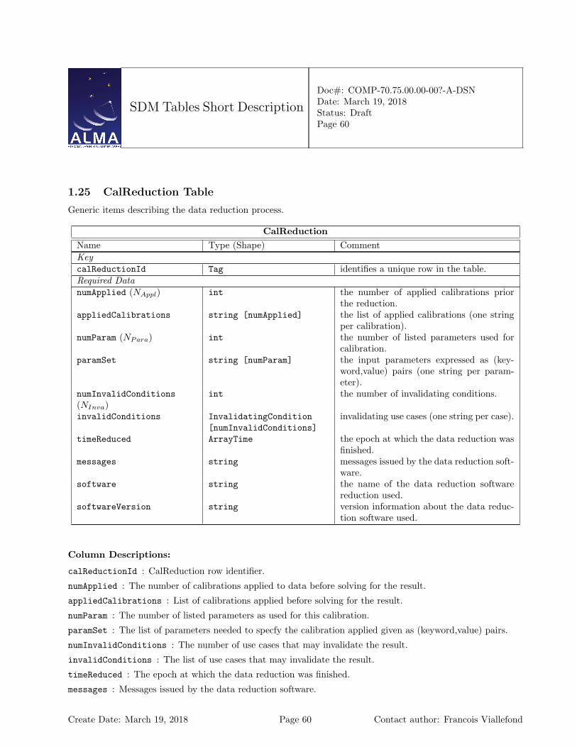
SDM Tables Short Description
Doc#: COMP-70.75.00.00-00?-A-DSNDate: March 19, 2018Status: DraftPage 60
1.25 CalReduction Table
Generic items describing the data reduction process.
CalReductionName Type (Shape) CommentKeycalReductionId Tag identifies a unique row in the table.Required DatanumApplied (NAppl) int the number of applied calibrations prior
the reduction.appliedCalibrations string [numApplied] the list of applied calibrations (one string
per calibration).numParam (NPara) int the number of listed parameters used for
calibration.paramSet string [numParam] the input parameters expressed as (key-
word,value) pairs (one string per param-eter).
numInvalidConditions(NInva)
int the number of invalidating conditions.
invalidConditions InvalidatingCondition[numInvalidConditions]
invalidating use cases (one string per case).
timeReduced ArrayTime the epoch at which the data reduction wasfinished.
messages string messages issued by the data reduction soft-ware.
software string the name of the data reduction softwarereduction used.
softwareVersion string version information about the data reduc-tion software used.
Column Descriptions:
calReductionId : CalReduction row identifier.
numApplied : The number of calibrations applied to data before solving for the result.
appliedCalibrations : List of calibrations applied before solving for the result.
numParam : The number of listed parameters as used for this calibration.
paramSet : The list of parameters needed to specfy the calibration applied given as (keyword,value) pairs.
numInvalidConditions : The number of use cases that may invalidate the result.
invalidConditions : The list of use cases that may invalidate the result.
timeReduced : The epoch at which the data reduction was finished.
messages : Messages issued by the data reduction software.
Create Date: March 19, 2018 Page 60 Contact author: Francois Viallefond

SDM Tables Short Description
Doc#: COMP-70.75.00.00-00?-A-DSNDate: March 19, 2018Status: DraftPage 61
software : The name of the data reduction software used to derive the result.
softwareVersion : The version of the data reduction spftware used to derive the result.
Create Date: March 19, 2018 Page 61 Contact author: Francois Viallefond

SDM Tables Short Description
Doc#: COMP-70.75.00.00-00?-A-DSNDate: March 19, 2018Status: DraftPage 62
1.26 CalSeeing Table
The seeing parameters deduced from TelCal calibrations.
CalSeeingName Type (Shape) CommentKeyatmPhaseCorrection AtmPhaseCorrection describes how the atmospheric phase cor-
rection has been applied.calDataId Tag refers to a unique row in CalData Table.calReductionId Tag refers to a unique row in CalReduction Ta-
ble.Required DatastartValidTime ArrayTime the start time of result validity period.endValidTime ArrayTime the end time of result validity period.frequencyRange Frequency [2] the range of frequencies over which this re-
sult is valid.integrationTime Interval the duration of averaging for the evaluation
of the RMS.numBaseLengths (NBase) int the number of baselines for which the the
RMS phase data is evaluated.baselineLengths Length [numBaseLengths] the lengths of the baselines (one value per
baseline).phaseRMS Angle [numBaseLengths] the RMS of phase fluctuations (one value
per baseline).seeing Angle the seeing parameter, deduced for the LO1.seeingError Angle the uncertainty on the seeing parameter.Optional Dataexponent float the exponent of the spatial structure func-
tion.outerScale Length the outer scale.outerScaleRMS Angle the RMS of phase fluctuations at scale
length outerScale.
Column Descriptions:
atmPhaseCorrection : The atmospheric phase correction states for which result is given.
calDataId : CalData Table identifier.
calReductionId : CalReduction Table identifier.
startValidTime : The start of the time validity range for the result.
endValidTime : The end of the time validity range for the result.
frequencyRange : Frequency range over which the result is valid.TOPO
Create Date: March 19, 2018 Page 62 Contact author: Francois Viallefond
SDM Tables Short Description
Doc#: COMP-70.75.00.00-00?-A-DSNDate: March 19, 2018Status: DraftPage 63
integrationTime : Averaging time for evaluation of rms fluctuations.
numBaseLengths : The number of baselines for which the rms phase data is evaluated.
baselineLengths : The baseline lengths at which the phase rms is evaluated.
phaseRMS : Root mean squared phase fluctuations for each baseline length.
seeing : The seeing parameter deduced for the calculated rms phases. This is the half-power width of thebeam that would be synthesized if those phase fluctuations were not corrected.
seeingError : The uncertainty on seeing.
exponent : The exponents of the fitted power laws in the phase rms data. There may be two values (inner,outer) if an outer scale is given.
outerScale : The outer scale of turbulence (validity limit of power law in phase structure function).
outerScaleRMS : Root mean squared phase fluctuations at scale length outerScale. This number allows tocalculate the modelled phase structure function at any scale (above and below outerScale).
Create Date: March 19, 2018 Page 63 Contact author: Francois Viallefond

SDM Tables Short Description
Doc#: COMP-70.75.00.00-00?-A-DSNDate: March 19, 2018Status: DraftPage 64
1.27 CalWVR Table
Result of the water vapour radiometric calibration performed by TelCal.
CalWVRName Type (Shape) CommentKeyantennaName string the name of the antenna.calDataId Tag refers to a unique row in CalData Table.calReductionId Tag refers to unique row in CalReductionTable.Required DatastartValidTime ArrayTime the start time of result validity period.endValidTime ArrayTime the end time of result validity period.wvrMethod WVRMethod identifies the method used for the calibra-
tion.numInputAntennas (NInpu) int the number of input antennas (i.e. equiped
with functional WVRs).inputAntennaNames string
[numInputAntennas]the names of the input antennas (one stringper antenna).
numChan (NChan) int the number of frequency channels in theWVR receiver.
chanFreq Frequency [numChan] the channel frequencies (one value perchannel).
chanWidth Frequency [numChan] the widths of the channels (one value perchannel).
refTemp Temperature[numInputAntennas][numChan]
the reference temperatures (one value perinput antenna per channel).
numPoly (NPoly) int the number of polynomial coefficients.pathCoeff float [numInputAntennas]
[numChan] [numPoly]the path length coefficients (one value perinput antenna per channel per polynomialcoefficient).
polyFreqLimits Frequency [2] the limits of the interval of frequencies forwhich the path length coefficients are com-puted.
wetPath float [numPoly] The wet path as a function frequency (ex-pressed as a polynomial).
dryPath float [numPoly] The dry path as a function frequency (ex-pressed as a polynomial).
water Length The precipitable water vapor correspond-ing to the reference model.
Column Descriptions:
Create Date: March 19, 2018 Page 64 Contact author: Francois Viallefond
SDM Tables Short Description
Doc#: COMP-70.75.00.00-00?-A-DSNDate: March 19, 2018Status: DraftPage 65
antennaName : Refers uniquely to the hardware antenna object, as present in the original ASDM Antennatable.
calDataId : CalData Table identifier.
calReductionId : CalReduction Table identifier.
startValidTime : The start of the time validity range for the result.
endValidTime : The end of the time validity range for the result.
wvrMethod : Method used, e.g, ab initio, Empirical.
numInputAntennas : The number of antennas equipped with functional WVRs, from which the data shouldbe interpolated, using the path length coefficients calculated, to obtain the pathlength correction to beapplied to the antenna given as ’antennaName’.
inputAntennaNames :
inputAntennaNames : The names of the antennas equipped with functional WVRs, from which the data shouldbe interpolated, using the path length coefficients calculated, to obtain the pathlength correction to beapplied to the antenna given as ’antennaName’.
numChan : Number of frequency channels in the WVR receiver.
chanFreq : The center frequency of the WVR channels. TOPO
chanWidth : The frequency width of the WVR channels.
refTemp : The reference temperature TRcj for each WVR channel to be used in the path length formula.
numPoly : The number of polynomial coefficients given, to obtain the frequency dependence of the pathlengthcorrection.
pathCoeff : The path length coefficients to be used to obtain the pathlength correction to be applied to theantenna given as ’antennaName’. These are the coefficients Ckcj (k = 1,NPoly) used to obtain the pathlength as a linear combinations of the data from the NChan WVR channels (in temperature units). Eachcoefficient is a term of a polynomial expansion (NPoly coefficients) of the predicted path length as afunction of observing frequency in the astronomical band (frequency limits in PolyFreqLimits). Thesepolynomials are Chebichev polynomials in this frequency interval reduced to [−1., 1.]). For the givenAntenna (antennaName), the path length correction to be applied is:∑
j=1,NInpA
[ ∑c=1,NChan
Pcj(ν)(Tcj − TRcj)]
where
– TRcj is the reference WVR temperature for channel c of antenna j– Tcj is the observed WVR temperature for channel c of antenna j– Pcj(ν) is the value of the Chebichev polynomial with coefficients evaluated at sky frequency ν with
coefficents Ckcj (k = 1, NPoly)
In the most frequent case there is a single input antenna (AntennaName). If the WVR device on a givenantenna is not available or fails, the above formula gives the desired way to interpolate the correction forthat antenna, based of other antennas (close neighbours).
Create Date: March 19, 2018 Page 65 Contact author: Francois Viallefond

SDM Tables Short Description
Doc#: COMP-70.75.00.00-00?-A-DSNDate: March 19, 2018Status: DraftPage 66
polyFreqLimits : Frequency limits of the frequency interval for which the path length coefficients are com-puted.
wetPath : The wet path as a function of frequency expressed as Chebichev polynomial in the frequency rangereduced to [−1, 1]. This corresponds to the reference model that reproduces the average line shape and isused in the delay server to track the phases and delays, while the departures from the average water lineshape are used for the pathlength correction applied to the correlator.
dryPath : The dry path as a function of frequency expressed as a Chebicehv polynomial in the frequency rangereduced to [−1, 1]. This corresponds to the same reference model as wetPath.
water : long doc missing
Create Date: March 19, 2018 Page 66 Contact author: Francois Viallefond
SDM Tables Short Description
Doc#: COMP-70.75.00.00-00?-A-DSNDate: March 19, 2018Status: DraftPage 67
1.28 ConfigDescription Table
Defines the hardware configuration used to obtain the science data.
ConfigDescriptionName Type (Shape) CommentKeyconfigDescriptionId Tag identifies a unique row in the table.Required DatanumAntenna (NAnte) int the number of antennas.numDataDescription(NData)
int the number of data descriptions.
numFeed (NFeed) int the number of feeds.correlationMode CorrelationMode identifies the correlation mode.numAtmPhaseCorrection(NAtmP )
int the number of descriptions of the atmo-spheric phase correction.
atmPhaseCorrection AtmPhaseCorrection[numAtmPhaseCorrection]
describe how the atmospheric phase cor-rections have been applied (one value percorrection).
processorType ProcessorType identifies the generic processor’s type.spectralType SpectralResolutionType identifies the spectral type of the data.antennaId Tag [numAntenna] identifies numAntenna rows in AntennaT-
able.feedId int [numAntenna*numFeed] refers to many collections of rows in the
Feed Table.switchCycleId Tag [numDataDescription] refers to a unique row in the SwitchCycle
Table.dataDescriptionId Tag [numDataDescription] refers to one or more rows in DataDescrip-
tionTable.processorId Tag refers to a unique row in ProcessorTable.Optional DataphasedArrayList int [numAntenna] phased array identifiers.numAssocValues (NAsso) int the number of associated config descrip-
tions.assocNature SpectralResolutionType
[numAssocValues]the natures of the associations with otherconfig descriptions (one value per associa-tion).
assocConfigDescriptionId Tag [numAssocValues] refers to one or more rows in ConfigDe-scriptionTable.
Column Descriptions:
configDescriptionId : Identifies the row in the Configuration Description Table.
numAntenna : The number of antennas used (given by the antennaId array).
Create Date: March 19, 2018 Page 67 Contact author: Francois Viallefond
SDM Tables Short Description
Doc#: COMP-70.75.00.00-00?-A-DSNDate: March 19, 2018Status: DraftPage 68
numDataDescription : Number of data descriptions for this row. This is equal to the number of spectralwindows.
numFeed : Number of feeds (given by the feedId array). For ALMA, numFeed is always one and feedId iszero.
correlationMode : The correlation mode used; for ALMA this is either Autocorrelation only, or Correlationand Autocorrelation.
numAtmPhaseCorrection : Number of Atmospheric Phase Corrections.
atmPhaseCorrection : The atmospheric phase correction states of data given (corrected, uncorrected, or both).
processorType : The generic processor type, such as, e.g., CORRELATOR, SPECTROMETER, or RA-DIOMETER.
spectralType : The spectral type of this data. It may be e.g direct spectral processor data (at full resolution),or channel averaged spectral procesor data, or total power detector data.
antennaId : The number of antennas used (given by the antennaId table).
feedId : Specifies which feed was used in the Feed Table.
switchCycleId : SwitchCycle Table identifier.
dataDescriptionId : DataDescription Table identifier.
processorId : The Processor Identifier provides a direct link to a row in the Processor Table.
phasedArrayList : List of phased array identifiers; normally not used for ALMA.
numAssocValues : The number of associated config descriptions.
assocNature : The nature of the associations established by the assocConfigDescriptionId array.
assocConfigDescriptionId : ConfigDescription Table identifier
Create Date: March 19, 2018 Page 68 Contact author: Francois Viallefond

SDM Tables Short Description
Doc#: COMP-70.75.00.00-00?-A-DSNDate: March 19, 2018Status: DraftPage 69
1.29 CorrelatorMode Table
Contains information on a Correlator processor.
CorrelatorModeName Type (Shape) CommentKeycorrelatorModeId Tag refers to a unique row in the table.Required DatanumBaseband (NBase) int the number of basebands.basebandNames BasebandName
[numBaseband]identifies the basebands (one value perbasebands).
basebandConfig int [numBaseband] encodes the basebands configurations (onevalue per baseband).
accumMode AccumMode identifies the accumulation mode.binMode int the binning mode.numAxes (NAxes) int the number of axes in the binary data
blocks.axesOrderArray AxisName [numAxes] the order of axes in the binary data blocks.filterMode FilterMode [numBaseband] identifies the filters modes (one value per
baseband).correlatorName CorrelatorName identifies the correlator’s name.
Column Descriptions:
correlatorModeId : Identifies the row in the Correlator Mode Table.
numBaseband : The number of baseband pairs used; this may be up to four for ALMA. A pair has two orthogonalpolarization channels.
basebandNames : Baseband names, that is the baseband pairs that are used ; there are four for ALMA.
basebandConfig : Baseband Configuration; for ALMA currently expressed as a number like ’103’ for Timedivision mode, or ’1’ for tunable filter mode; there is one of these for each baseband pair.
accumMode : The accumulation mode: for ALMA this is either FAST (For 1ms dumps, autocorrelation only)or NORMAL (for 16ms minimum dumps, and simultaneous correlation and autocorrelation).
binMode : The number of data bins: data bins are used together for switch cycles. For instance we have twofor frequency switching of nutator switching, but one only for interferometry.
numAxes : The number of axes in the binary data blocks.
axesOrderArray : The standard order of axes in the binary data blocks. Axes may be omitted (See the BDFdocumentation).
filterMode : The mode of operation of the digital filters used at the input of the ALMA correlator. These arethe TDM (Time Division Mode) or TFB (Tunable Filter Bank) modes.
correlatorName : The name of the correlator; in ALMA we have the ’baseline’ correlator and the ’ACA’correlator.
Create Date: March 19, 2018 Page 69 Contact author: Francois Viallefond
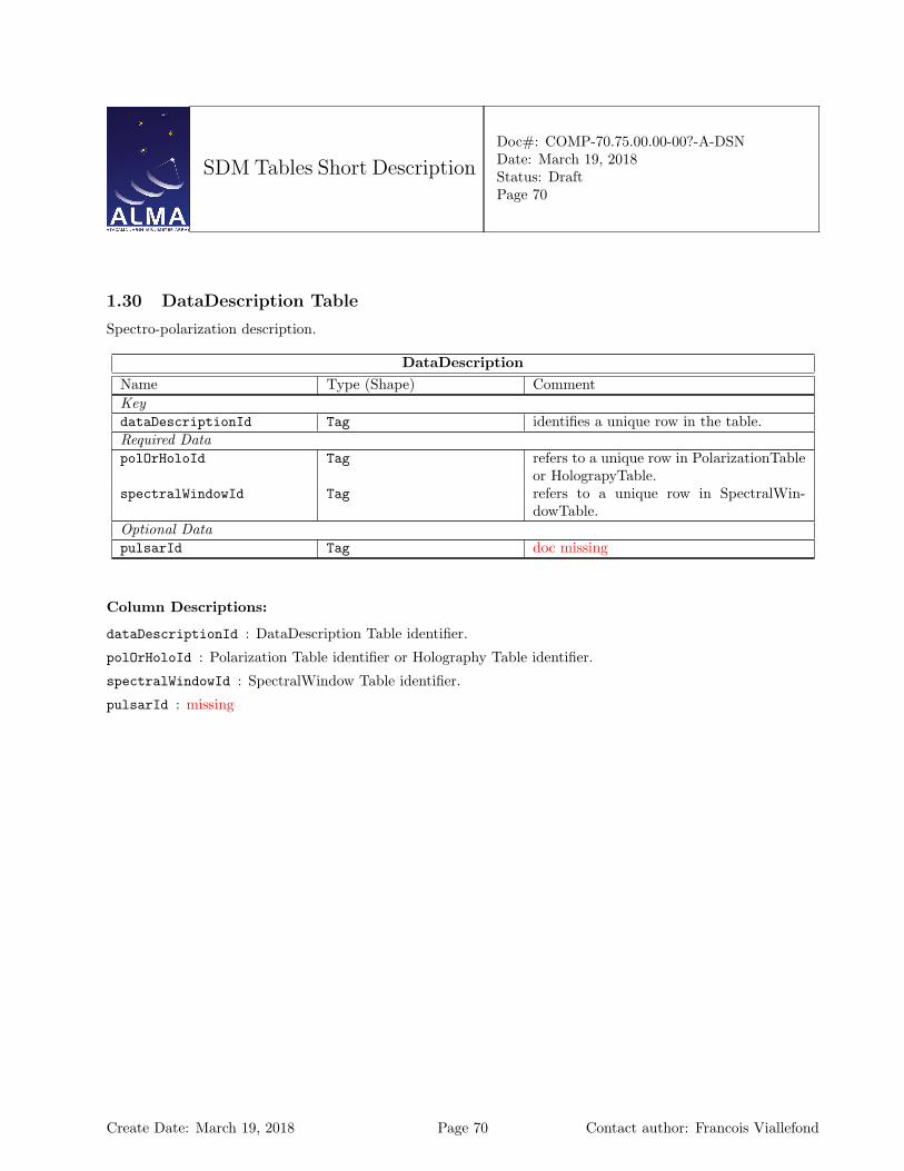
SDM Tables Short Description
Doc#: COMP-70.75.00.00-00?-A-DSNDate: March 19, 2018Status: DraftPage 70
1.30 DataDescription Table
Spectro-polarization description.
DataDescriptionName Type (Shape) CommentKeydataDescriptionId Tag identifies a unique row in the table.Required DatapolOrHoloId Tag refers to a unique row in PolarizationTable
or HolograpyTable.spectralWindowId Tag refers to a unique row in SpectralWin-
dowTable.Optional DatapulsarId Tag doc missing
Column Descriptions:
dataDescriptionId : DataDescription Table identifier.
polOrHoloId : Polarization Table identifier or Holography Table identifier.
spectralWindowId : SpectralWindow Table identifier.
pulsarId : missing
Create Date: March 19, 2018 Page 70 Contact author: Francois Viallefond

SDM Tables Short Description
Doc#: COMP-70.75.00.00-00?-A-DSNDate: March 19, 2018Status: DraftPage 71
1.31 DelayModel Table
Contains the delay model components. For ALMA this includes all TMCDB delay model components.
DelayModelName Type (Shape) CommentKeyantennaId Tag refers to a unique row in AntennaTable.spectralWindowId Tag refers to a unique row in SpectraWin-
dowTable.timeInterval ArrayTimeInterval time interval for which the row’s content is
valid.Required DatanumPoly (NPoly) int the number of coefficients of the polynomi-
als.phaseDelay double [numPoly] the phase delay polynomial (rad).phaseDelayRate double [numPoly] Phase delay rate polynomial (rad/s).groupDelay double [numPoly] Group delay polynomial (s).groupDelayRate double [numPoly] Group delay rate polynomial (s/s)fieldId Tag doc missingOptional DatatimeOrigin ArrayTime value used as the origin for the evaluation
of the polynomials.atmosphericGroupDelay double Atmosphere group delay.atmosphericGroupDelayRate double Atmosphere group delay rate.geometricDelay double Geometric delay.geometricDelayRate double Geometric delay.numLO (NLO) int the number of local oscillators.LOOffset Frequency [numLO] Local oscillator offset.LOOffsetRate Frequency [numLO] Local oscillator offset rate.dispersiveDelay double Dispersive delay.dispersiveDelayRate double Dispersive delay rate.atmosphericDryDelay double the dry atmospheric delay component.atmosphericWetDelay double the wet atmospheric delay.padDelay double Pad delay.antennaDelay double Antenna delay.numReceptor (NRece) int doc missingpolarizationType PolarizationType
[numReceptor]describes the polarizations of the receptors(one value per receptor).
electronicDelay double [numReceptor] the electronic delay.electronicDelayRate double [numReceptor] the electronic delay rate.receiverDelay double [numReceptor] the receiver delay.IFDelay double [numReceptor] the intermediate frequency delay.LODelay double [numReceptor] the local oscillator delay.crossPolarizationDelay double the cross polarization delay.
Create Date: March 19, 2018 Page 71 Contact author: Francois Viallefond

SDM Tables Short Description
Doc#: COMP-70.75.00.00-00?-A-DSNDate: March 19, 2018Status: DraftPage 72
Column Descriptions:
antennaId : Antenna identifier, as indexed from an element in the antennaArray collection in the configDe-scription table.
spectralWindowId : long doc missing
timeInterval : Time interval for which the parameters in the row are valid. The same reference used for theTime column in the Main Table must be used.
numPoly : Series order for the delay time polynomial expansions.
phaseDelay : long doc missing
phaseDelayRate : long doc missing
groupDelay : long doc missing
groupDelayRate : long doc missing
fieldId : missing
timeOrigin : long doc missing
atmosphericGroupDelay : long doc missing
atmosphericGroupDelayRate : long doc missing
geometricDelay : long doc missing
geometricDelayRate : long doc missing
numLO : long doc missing
LOOffset : long doc missing
LOOffsetRate : long doc missing
dispersiveDelay : long doc missing
dispersiveDelayRate : long doc missing
atmosphericDryDelay : Dry atmosphere delay component.
atmosphericWetDelay : Wet atmosphere delay component.
padDelay : long doc missing
antennaDelay : long doc missing
numReceptor : missing
polarizationType : long doc missing
electronicDelay : long doc missing
electronicDelayRate : long doc missing
receiverDelay : long doc missing
IFDelay : long doc missing
LODelay : long doc missing
crossPolarizationDelay : long doc missing
Create Date: March 19, 2018 Page 72 Contact author: Francois Viallefond

SDM Tables Short Description
Doc#: COMP-70.75.00.00-00?-A-DSNDate: March 19, 2018Status: DraftPage 73
1.32 DelayModelFixedParameters Table
missing documentation
DelayModelFixedParametersName Type (Shape) CommentKeydelayModelFixedParametersIdTag identifies a unique row in the table.Required DatadelayModelVersion string should include the name of the software
and its version. Something like ”CALCv11” or ”VDT v1.0” or ”MODEST v2.1”.
execBlockId Tag refers to a unique row of the ExecBlocktable.
Optional DatagaussConstant AngularRate the Gauss gravitational constant (should
be of order 1.720209895.10−2rad/d but inSI units of rads−1).
newtonianConstant double the newtonian constant of grav-itation (should be of order6.67259.10−11m3kg−1s2).
gravity double the gravity acceleration in ms−2.earthFlattening double the ratio of equatorial to polar radii.earthRadius Length the earth equatorial radius in m.moonEarthMassRatio double doc missingephemerisEpoch string should always be ’J2000’.earthTideLag double doc missingearthGM double the earth gravitation constant in m3s−2.moonGM double the moon gravitation constant in m3s−2.sunGM double the sun gravitation constant in m3s−2.loveNumberH double the earth global Love number H.loveNumberL double the earth global Love number L.precessionConstant AngularRate the general precession constant in
arcsec s−1.lightTime1AU double the light time for 1 AU in seconds.speedOfLight Speed the speed of light in ms−1.delayModelFlags string the delay model switches.
Column Descriptions:
delayModelFixedParametersId : long doc missing
delayModelVersion : long doc missing
execBlockId : long doc missing
Create Date: March 19, 2018 Page 73 Contact author: Francois Viallefond
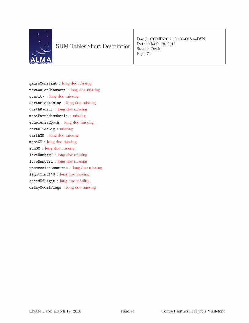
SDM Tables Short Description
Doc#: COMP-70.75.00.00-00?-A-DSNDate: March 19, 2018Status: DraftPage 74
gaussConstant : long doc missing
newtonianConstant : long doc missing
gravity : long doc missing
earthFlattening : long doc missing
earthRadius : long doc missing
moonEarthMassRatio : missing
ephemerisEpoch : long doc missing
earthTideLag : missing
earthGM : long doc missing
moonGM : long doc missing
sunGM : long doc missing
loveNumberH : long doc missing
loveNumberL : long doc missing
precessionConstant : long doc missing
lightTime1AU : long doc missing
speedOfLight : long doc missing
delayModelFlags : long doc missing
Create Date: March 19, 2018 Page 74 Contact author: Francois Viallefond
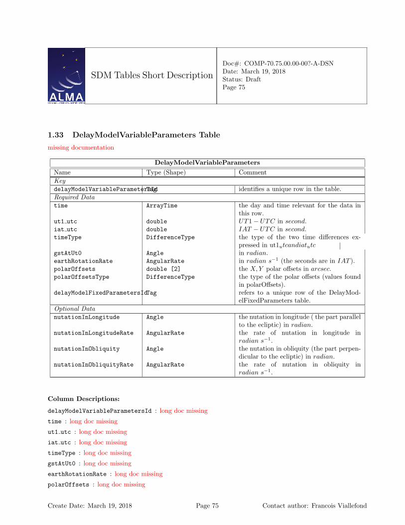
SDM Tables Short Description
Doc#: COMP-70.75.00.00-00?-A-DSNDate: March 19, 2018Status: DraftPage 75
1.33 DelayModelVariableParameters Table
missing documentation
DelayModelVariableParametersName Type (Shape) CommentKeydelayModelVariableParametersIdTag identifies a unique row in the table.Required Datatime ArrayTime the day and time relevant for the data in
this row.ut1 utc double UT1− UTC in second.iat utc double IAT − UTC in second.timeType DifferenceType the type of the two time differences ex-
pressed in ut1utcandiatutcgstAtUt0 Angle in radian.earthRotationRate AngularRate in radian s−1 (the seconds are in IAT ).polarOffsets double [2] the X,Y polar offsets in arcsec.polarOffsetsType DifferenceType the type of the polar offsets (values found
in polarOffsets).delayModelFixedParametersIdTag refers to a unique row of the DelayMod-
elFixedParameters table.Optional DatanutationInLongitude Angle the nutation in longitude ( the part parallel
to the ecliptic) in radian.nutationInLongitudeRate AngularRate the rate of nutation in longitude in
radian s−1.nutationInObliquity Angle the nutation in obliquity (the part perpen-
dicular to the ecliptic) in radian.nutationInObliquityRate AngularRate the rate of nutation in obliquity in
radian s−1.
Column Descriptions:
delayModelVariableParametersId : long doc missing
time : long doc missing
ut1 utc : long doc missing
iat utc : long doc missing
timeType : long doc missing
gstAtUt0 : long doc missing
earthRotationRate : long doc missing
polarOffsets : long doc missing
Create Date: March 19, 2018 Page 75 Contact author: Francois Viallefond

SDM Tables Short Description
Doc#: COMP-70.75.00.00-00?-A-DSNDate: March 19, 2018Status: DraftPage 76
polarOffsetsType : long doc missing
delayModelFixedParametersId : long doc missing
nutationInLongitude : long doc missing
nutationInLongitudeRate : long doc missing
nutationInObliquity : long doc missing
nutationInObliquityRate : long doc missing
Create Date: March 19, 2018 Page 76 Contact author: Francois Viallefond
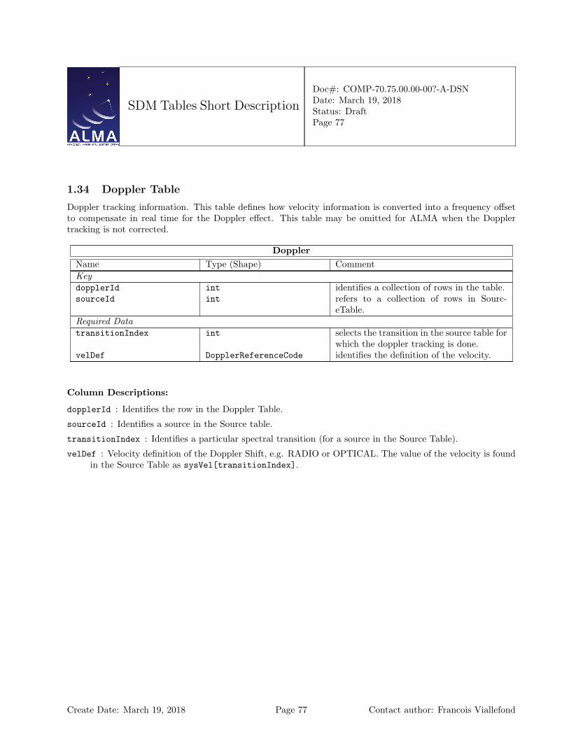
SDM Tables Short Description
Doc#: COMP-70.75.00.00-00?-A-DSNDate: March 19, 2018Status: DraftPage 77
1.34 Doppler Table
Doppler tracking information. This table defines how velocity information is converted into a frequency offsetto compensate in real time for the Doppler effect. This table may be omitted for ALMA when the Dopplertracking is not corrected.
DopplerName Type (Shape) CommentKeydopplerId int identifies a collection of rows in the table.sourceId int refers to a collection of rows in Sourc-
eTable.Required DatatransitionIndex int selects the transition in the source table for
which the doppler tracking is done.velDef DopplerReferenceCode identifies the definition of the velocity.
Column Descriptions:
dopplerId : Identifies the row in the Doppler Table.
sourceId : Identifies a source in the Source table.
transitionIndex : Identifies a particular spectral transition (for a source in the Source Table).
velDef : Velocity definition of the Doppler Shift, e.g. RADIO or OPTICAL. The value of the velocity is foundin the Source Table as sysVel[transitionIndex].
Create Date: March 19, 2018 Page 77 Contact author: Francois Viallefond
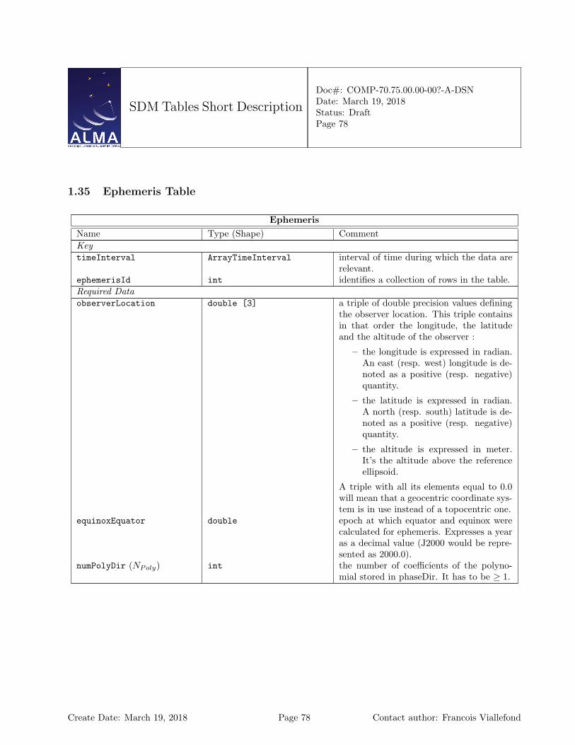
SDM Tables Short Description
Doc#: COMP-70.75.00.00-00?-A-DSNDate: March 19, 2018Status: DraftPage 78
1.35 Ephemeris Table
EphemerisName Type (Shape) CommentKeytimeInterval ArrayTimeInterval interval of time during which the data are
relevant.ephemerisId int identifies a collection of rows in the table.Required DataobserverLocation double [3] a triple of double precision values defining
the observer location. This triple containsin that order the longitude, the latitudeand the altitude of the observer :
– the longitude is expressed in radian.An east (resp. west) longitude is de-noted as a positive (resp. negative)quantity.
– the latitude is expressed in radian.A north (resp. south) latitude is de-noted as a positive (resp. negative)quantity.
– the altitude is expressed in meter.It’s the altitude above the referenceellipsoid.
A triple with all its elements equal to 0.0will mean that a geocentric coordinate sys-tem is in use instead of a topocentric one.
equinoxEquator double epoch at which equator and equinox werecalculated for ephemeris. Expresses a yearas a decimal value (J2000 would be repre-sented as 2000.0).
numPolyDir (NPoly) int the number of coefficients of the polyno-mial stored in phaseDir. It has to be ≥ 1.
Create Date: March 19, 2018 Page 78 Contact author: Francois Viallefond
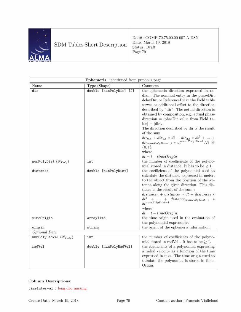
SDM Tables Short Description
Doc#: COMP-70.75.00.00-00?-A-DSNDate: March 19, 2018Status: DraftPage 79
Ephemeris – continued from previous pageName Type (Shape) Commentdir double [numPolyDir] [2] the ephemeris direction expressed in ra-
dian. The nominal entry in the phaseDir,delayDir, or ReferenceDir in the Field tableserves as additional offset to the directiondescribed by ”dir”. The actual direction isobtained by composition, e.g. actual phasedirection = [phasDir value from Field ta-ble] + [dir].The direction described by dir is the resultof the sumdir0,i + dir1,i ∗ dt + dir2,i ∗ dt2 + ... +dirnumPolyDir−1,i ∗ dtnumPolyDir−1,∀i ∈{0, 1}wheredt = t− timeOrigin
numPolyDist (NPoly) int the number of coefficients of the polyno-mial stored in distance. It has to be ≥ 1.
distance double [numPolyDist] the coefficiens of the polynomial used tocalculate the distance, expressed in meter,to the object from the position of the an-tenna along the given direction. This dis-tance is the result of the sum :distance0 + distance1 ∗ dt + distance2 ∗dt2 + ... + distancenumPolyDist−1 ∗dtnumPolyDist−1
wheredt = t− timeOrigin.
timeOrigin ArrayTime the time origin used in the evaluation ofthe polynomial expressions.
origin string the origin of the ephemeris information.Optional DatanumPolyRadVel (NPoly) int the number of coefficients of the polyno-
mial stored in radVel . It has to be ≥ 1.radVel double [numPolyRadVel] the coefficients of a polynomial expressing
a radial velocity as a function of the timeexpressed in m/s. The time origin used totabulate the polynomial is stored in time-Origin.
Column Descriptions:
timeInterval : long doc missing
Create Date: March 19, 2018 Page 79 Contact author: Francois Viallefond

SDM Tables Short Description
Doc#: COMP-70.75.00.00-00?-A-DSNDate: March 19, 2018Status: DraftPage 80
ephemerisId : long doc missing
observerLocation : long doc missing
equinoxEquator : long doc missing
numPolyDir : long doc missing
dir : long doc missing
numPolyDist : long doc missing
distance : long doc missing
timeOrigin : long doc missing
origin : Typically one should see here e.g. a JPL identifier, eventually orbital parameters, etc...”. for example,one might see in that string:origin = ’JPL Horizons - DE405,JUP230’In any case, the observing system of ALMA or VLA should feel free to put in there whatever string theythink best describes the information.
numPolyRadVel : long doc missing
radVel : long doc missing
Create Date: March 19, 2018 Page 80 Contact author: Francois Viallefond
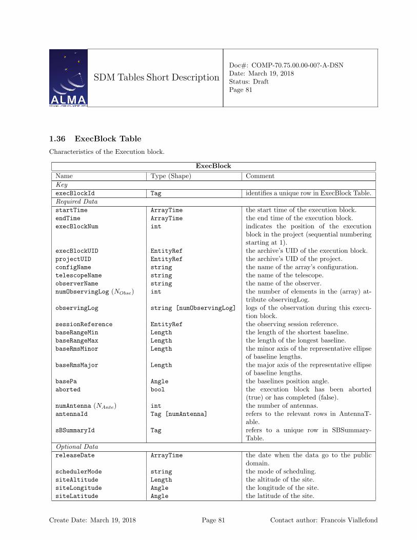
SDM Tables Short Description
Doc#: COMP-70.75.00.00-00?-A-DSNDate: March 19, 2018Status: DraftPage 81
1.36 ExecBlock Table
Characteristics of the Execution block.
ExecBlockName Type (Shape) CommentKeyexecBlockId Tag identifies a unique row in ExecBlock Table.Required DatastartTime ArrayTime the start time of the execution block.endTime ArrayTime the end time of the execution block.execBlockNum int indicates the position of the execution
block in the project (sequential numberingstarting at 1).
execBlockUID EntityRef the archive’s UID of the execution block.projectUID EntityRef the archive’s UID of the project.configName string the name of the array’s configuration.telescopeName string the name of the telescope.observerName string the name of the observer.numObservingLog (NObse) int the number of elements in the (array) at-
tribute observingLog.observingLog string [numObservingLog] logs of the observation during this execu-
tion block.sessionReference EntityRef the observing session reference.baseRangeMin Length the length of the shortest baseline.baseRangeMax Length the length of the longest baseline.baseRmsMinor Length the minor axis of the representative ellipse
of baseline lengths.baseRmsMajor Length the major axis of the representative ellipse
of baseline lengths.basePa Angle the baselines position angle.aborted bool the execution block has been aborted
(true) or has completed (false).numAntenna (NAnte) int the number of antennas.antennaId Tag [numAntenna] refers to the relevant rows in AntennaT-
able.sBSummaryId Tag refers to a unique row in SBSummary-
Table.Optional DatareleaseDate ArrayTime the date when the data go to the public
domain.schedulerMode string the mode of scheduling.siteAltitude Length the altitude of the site.siteLongitude Angle the longitude of the site.siteLatitude Angle the latitude of the site.
Create Date: March 19, 2018 Page 81 Contact author: Francois Viallefond

SDM Tables Short Description
Doc#: COMP-70.75.00.00-00?-A-DSNDate: March 19, 2018Status: DraftPage 82
ExecBlock – continued from previous pageName Type (Shape) CommentobservingScript string The text of the observation script.observingScriptUID EntityRef A reference to the Entity which contains
the observing script.scaleId Tag refers to a unique row in the table Scale.
Column Descriptions:
execBlockId : Identifies the row in the ExecBlock Table.
startTime : Scheduled time of start of data taking.
endTime : Scheduled time of end of data taking.
execBlockNum : Number of the ExecBlock: in ALMA Execution blocks in a project are consecutively numberedstarting from 1.
execBlockUID : Archive UID of the ExecBlock (the container of the data set).
projectUID : The archive UID of the Project.
configName : Name of the array baseline configuration.
telescopeName : Name of the telescope (e.g. ’ALMA’)
observerName : Name of the observer.
numObservingLog : long doc missing
observingLog : Logs of observations (information entered at execution time by the Operator).
sessionReference : This is useful for grouping execblocks. Data capture know the session reference so thisinformation is easily available.
baseRangeMin : Length of the minimum baseline. For Alma this is expected to be filled from the unprojectedbaselines available in the array being used in this ExecBlock.
baseRangeMax : Length of the maximum baseline. For Alma this is expected to be filled from the unprojectedbaselines available in the array being used in this ExecBlock.
baseRmsMinor : Minor axis of the representative ellipse of baseline lengths. For Alma this is expected to befilled from the unprojected baselines available in the array being used in this ExecBlock.
baseRmsMajor : Major axis of the representative ellipse of baseline lengths. For Alma this is expected to befilled from the unprojected baselines available in the array being used in this ExecBlock.
basePa : Position angle of the major axis on the representative ellipse of baseline lengths. For Alma this isexpected to be filled from the unprojected baselines available in the array being used in this ExecBlock.
aborted : Set when the execution was aborted.
numAntenna : Number of antennas used in the ExecBlock.
antennaId : Antenna Table identifier.
sBSummaryId : SBSummary Table identifier.
Create Date: March 19, 2018 Page 82 Contact author: Francois Viallefond

SDM Tables Short Description
Doc#: COMP-70.75.00.00-00?-A-DSNDate: March 19, 2018Status: DraftPage 83
releaseDate : The date when the data will become public.
schedulerMode : Mode of the Scheduling when this data was taken (Dynamic, Interactive, ...)
siteAltitude : Latitude of the site (array center).
siteLongitude : Longitude of the site (array center).
siteLatitude : Latitude of the site (array center).
observingScript : long doc missing
observingScriptUID : long doc missing
scaleId : long doc missing
Create Date: March 19, 2018 Page 83 Contact author: Francois Viallefond
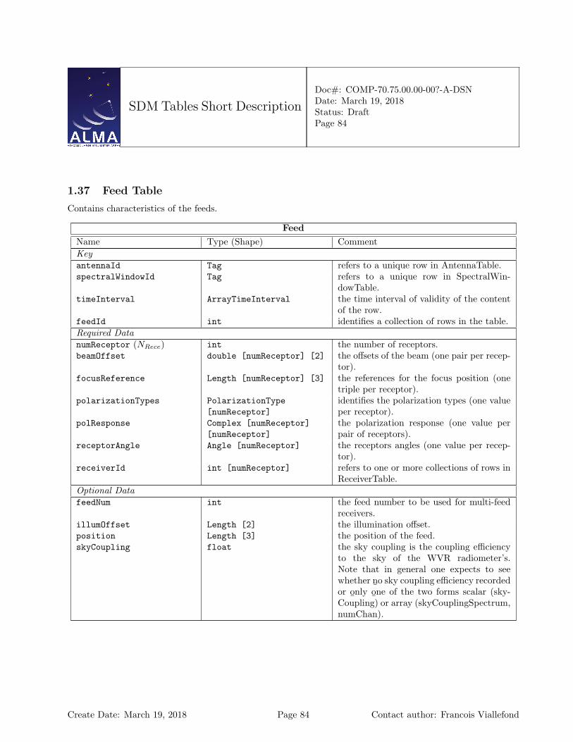
SDM Tables Short Description
Doc#: COMP-70.75.00.00-00?-A-DSNDate: March 19, 2018Status: DraftPage 84
1.37 Feed Table
Contains characteristics of the feeds.
FeedName Type (Shape) CommentKeyantennaId Tag refers to a unique row in AntennaTable.spectralWindowId Tag refers to a unique row in SpectralWin-
dowTable.timeInterval ArrayTimeInterval the time interval of validity of the content
of the row.feedId int identifies a collection of rows in the table.Required DatanumReceptor (NRece) int the number of receptors.beamOffset double [numReceptor] [2] the offsets of the beam (one pair per recep-
tor).focusReference Length [numReceptor] [3] the references for the focus position (one
triple per receptor).polarizationTypes PolarizationType
[numReceptor]identifies the polarization types (one valueper receptor).
polResponse Complex [numReceptor][numReceptor]
the polarization response (one value perpair of receptors).
receptorAngle Angle [numReceptor] the receptors angles (one value per recep-tor).
receiverId int [numReceptor] refers to one or more collections of rows inReceiverTable.
Optional DatafeedNum int the feed number to be used for multi-feed
receivers.illumOffset Length [2] the illumination offset.position Length [3] the position of the feed.skyCoupling float the sky coupling is the coupling efficiency
to the sky of the WVR radiometer’s.Note that in general one expects to seewhether n
¯o sky coupling efficiency recorded
or o¯nly o
¯ne of the two forms scalar (sky-
Coupling) or array (skyCouplingSpectrum,numChan).
Create Date: March 19, 2018 Page 84 Contact author: Francois Viallefond

SDM Tables Short Description
Doc#: COMP-70.75.00.00-00?-A-DSNDate: March 19, 2018Status: DraftPage 85
Feed – continued from previous pageName Type (Shape) CommentnumChan (NChan) int the size of skyCouplingSpectrum. This at-
tribute must be present when the (array)attribute skyCouplingSpectrum is presentsince it defines its number of elements. Thevalue of this attribute must be equal to thevalue of numChan in the row of the Spec-tralWindow table refered to by spectral-WindowId.
skyCouplingSpectrum float [numChan] the sky coupling is the coupling efficiencyto the sky of the WVR radiometer’s. Thiscolumn differs from the skyCoupling col-umn because it contains one value for eachof the individual channels of that spectral-Window. See the documentation of num-Chan for the size and the presence of thisattribute. Note that in general one expectsto see whether n
¯o sky coupling efficiency
recorded or o¯nly o
¯ne of the two forms scalar
(skyCoupling) or array (skyCouplingSpec-trum, numChan).
Column Descriptions:
antennaId : Antenna Table identifier.
spectralWindowId : SpectralWindow Table identifier.
timeInterval : Time Interval of validity of the feed information.
feedId : Feed Table identifier.
numReceptor : The number of receptors for which the result is given.
beamOffset : Offset of the beam.
focusReference : Reference for the focus position.
polarizationTypes : The polarization types of the receptors being used.
polResponse : The polarization response of the receptors.
receptorAngle : Position angle for X polarization direction.
receiverId : Points to the receivers corresponding to this feed.
feedNum : Feed number is to be used for multi-feed receivers (there are none in ALMA; so feedNum is alwaysone).
illumOffset : Illumination offset for this feed, measured in linear distance from the center of the primaryreflector. REFLECTOR
Create Date: March 19, 2018 Page 85 Contact author: Francois Viallefond
SDM Tables Short Description
Doc#: COMP-70.75.00.00-00?-A-DSNDate: March 19, 2018Status: DraftPage 86
position : The position of the feed.
skyCoupling : long doc missing
numChan : long doc missing
skyCouplingSpectrum : long doc missing
Create Date: March 19, 2018 Page 86 Contact author: Francois Viallefond
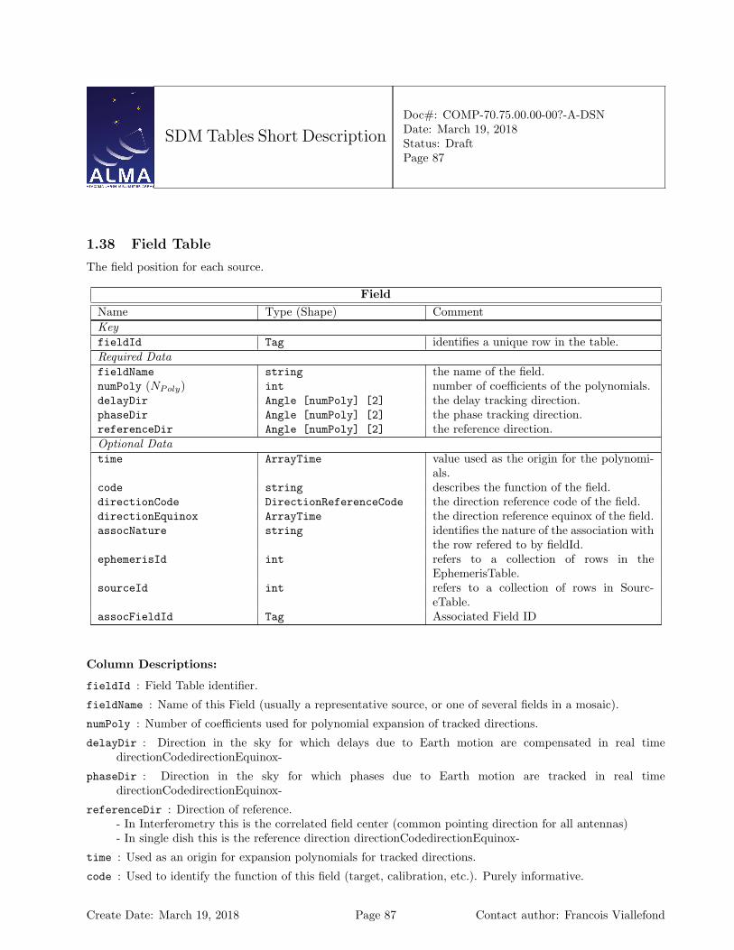
SDM Tables Short Description
Doc#: COMP-70.75.00.00-00?-A-DSNDate: March 19, 2018Status: DraftPage 87
1.38 Field Table
The field position for each source.
FieldName Type (Shape) CommentKeyfieldId Tag identifies a unique row in the table.Required DatafieldName string the name of the field.numPoly (NPoly) int number of coefficients of the polynomials.delayDir Angle [numPoly] [2] the delay tracking direction.phaseDir Angle [numPoly] [2] the phase tracking direction.referenceDir Angle [numPoly] [2] the reference direction.Optional Datatime ArrayTime value used as the origin for the polynomi-
als.code string describes the function of the field.directionCode DirectionReferenceCode the direction reference code of the field.directionEquinox ArrayTime the direction reference equinox of the field.assocNature string identifies the nature of the association with
the row refered to by fieldId.ephemerisId int refers to a collection of rows in the
EphemerisTable.sourceId int refers to a collection of rows in Sourc-
eTable.assocFieldId Tag Associated Field ID
Column Descriptions:
fieldId : Field Table identifier.
fieldName : Name of this Field (usually a representative source, or one of several fields in a mosaic).
numPoly : Number of coefficients used for polynomial expansion of tracked directions.
delayDir : Direction in the sky for which delays due to Earth motion are compensated in real timedirectionCodedirectionEquinox-
phaseDir : Direction in the sky for which phases due to Earth motion are tracked in real timedirectionCodedirectionEquinox-
referenceDir : Direction of reference.- In Interferometry this is the correlated field center (common pointing direction for all antennas)- In single dish this is the reference direction directionCodedirectionEquinox-
time : Used as an origin for expansion polynomials for tracked directions.
code : Used to identify the function of this field (target, calibration, etc.). Purely informative.
Create Date: March 19, 2018 Page 87 Contact author: Francois Viallefond
SDM Tables Short Description
Doc#: COMP-70.75.00.00-00?-A-DSNDate: March 19, 2018Status: DraftPage 88
directionCode : The common reference code for field directions in the row, if not J2000.
directionEquinox : The common reference equinox for field directions in the row, if required bydirectionCode.
assocNature : Gives the meaning of Associated Field rows.
ephemerisId : long doc missing
sourceId : Source Table identifier.
assocFieldId : Refers to a unique associate row in the table.
Create Date: March 19, 2018 Page 88 Contact author: Francois Viallefond
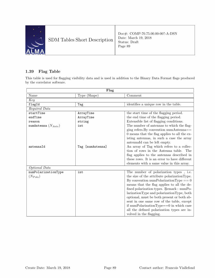
SDM Tables Short Description
Doc#: COMP-70.75.00.00-00?-A-DSNDate: March 19, 2018Status: DraftPage 89
1.39 Flag Table
This table is used for flagging visibility data and is used in addition to the Binary Data Format flags producedby the correlator software.
FlagName Type (Shape) CommentKeyflagId Tag identifies a unique row in the table.Required DatastartTime ArrayTime the start time of the flagging period.endTime ArrayTime the end time of the flagging period.reason string Extensible list of flagging conditions.numAntenna (NAnte) int The number of antennas to which the flag-
ging refers.By convention numAntenna==0 means that the flag applies to all the ex-isting antennas, in such a case the arrayantennaId can be left empty.
antennaId Tag [numAntenna] An array of Tag which refers to a collec-tion of rows in the Antenna table. Theflag applies to the antennas described inthese rows. It is an error to have differentelements with a same value in this array.
Optional DatanumPolarizationType(NPola)
int The number of polarization types , i.e.the size of the attribute polarizationType.By convention numPolarizationType == 0means that the flag applies to all the de-fined polarization types. R
¯emark : numPo-
larizationType and polarizationType, bothoptional, must be both present or both ab-sent in one same row of the table, exceptif numPolarizationType==0 in which caseall the defined polarization types are in-volved in the flagging.
Create Date: March 19, 2018 Page 89 Contact author: Francois Viallefond
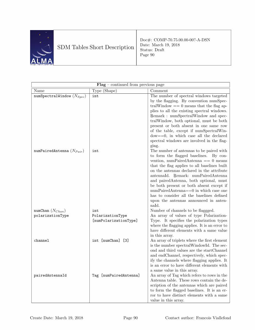
SDM Tables Short Description
Doc#: COMP-70.75.00.00-00?-A-DSNDate: March 19, 2018Status: DraftPage 90
Flag – continued from previous pageName Type (Shape) CommentnumSpectralWindow (NSpec) int The number of spectral windows targeted
by the flagging. By convention numSpec-tralWindow == 0 means that the flag ap-plies to all the existing spectral windows.R¯
emark : numSpectralWindow and spec-tralWindow, both optional, must be bothpresent or both absent in one same rowof the table, except if numSpectralWin-dow==0, in which case all the declaredspectral windows are involved in the flag-ging.
numPairedAntenna (NPair) int The number of antennas to be paired withto form the flagged baselines. By con-vention, numPairedAntenna == 0 meansthat the flag applies to all baselines builton the antennas declared in the attributeantennaId. R
¯emark: numPairedAntenna
and pairedAntenna, both optional, mustbe both present or both absent except ifnumPairedAntenna==0 in which case onehas to consider all the baselines definedupon the antennas announced in anten-naId.
numChan (NChan) int Number of channels to be flaggged.polarizationType PolarizationType
[numPolarizationType]An array of values of type Polarization-Type. It specifies the polarization typeswhere the flagging applies. It is an error tohave different elements with a same valuein this array.
channel int [numChan] [3] An array of triplets where the first elementis the number spectralWindowId. The sec-ond and third values are the startChanneland endChannel, respectively, which spec-ify the channels where flagging applies. Itis an error to have different elements witha same value in this array.
pairedAntennaId Tag [numPairedAntenna] An array of Tag which refers to rows in theAntenna table. These rows contain the de-scription of the antennas which are pairedto form the flagged baselines. It is an er-ror to have distinct elements with a samevalue in this array.
Create Date: March 19, 2018 Page 90 Contact author: Francois Viallefond
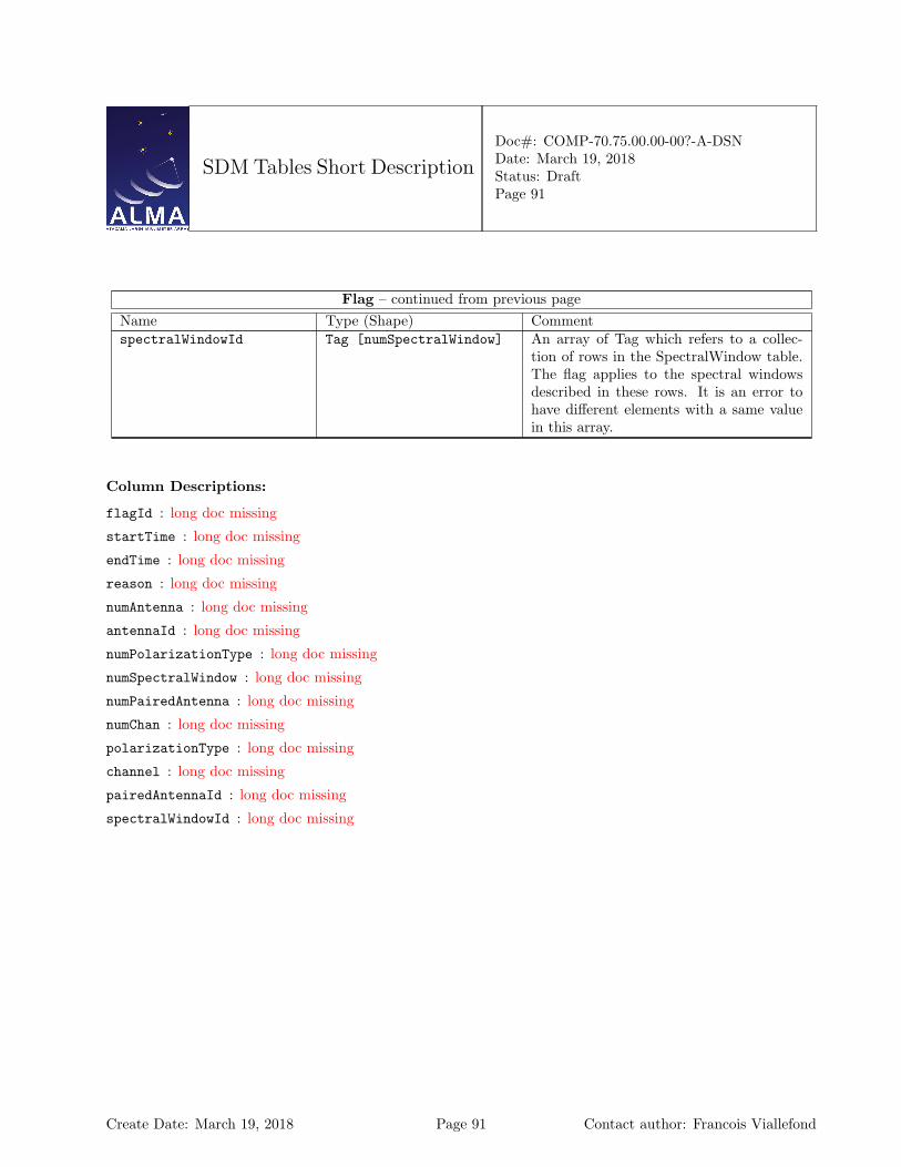
SDM Tables Short Description
Doc#: COMP-70.75.00.00-00?-A-DSNDate: March 19, 2018Status: DraftPage 91
Flag – continued from previous pageName Type (Shape) CommentspectralWindowId Tag [numSpectralWindow] An array of Tag which refers to a collec-
tion of rows in the SpectralWindow table.The flag applies to the spectral windowsdescribed in these rows. It is an error tohave different elements with a same valuein this array.
Column Descriptions:
flagId : long doc missing
startTime : long doc missing
endTime : long doc missing
reason : long doc missing
numAntenna : long doc missing
antennaId : long doc missing
numPolarizationType : long doc missing
numSpectralWindow : long doc missing
numPairedAntenna : long doc missing
numChan : long doc missing
polarizationType : long doc missing
channel : long doc missing
pairedAntennaId : long doc missing
spectralWindowId : long doc missing
Create Date: March 19, 2018 Page 91 Contact author: Francois Viallefond
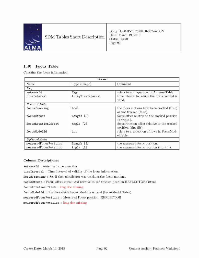
SDM Tables Short Description
Doc#: COMP-70.75.00.00-00?-A-DSNDate: March 19, 2018Status: DraftPage 92
1.40 Focus Table
Contains the focus information.
FocusName Type (Shape) CommentKeyantennaId Tag refers to a unique row in AntennaTable.timeInterval ArrayTimeInterval time interval for which the row’s content is
valid.Required DatafocusTracking bool the focus motions have been tracked (true)
or not tracked (false).focusOffset Length [3] focus offset relative to the tracked position
(a triple ).focusRotationOffset Angle [2] focus rotation offset relative to the tracked
position (tip, tilt).focusModelId int refers to a collection of rows in FocusMod-
elTable.Optional DatameasuredFocusPosition Length [3] the measured focus position.measuredFocusRotation Angle [2] the measured focus rotation (tip, tilt).
Column Descriptions:
antennaId : Antenna Table identifier.
timeInterval : Time Interval of validity of the focus information.
focusTracking : Set if the subreflector was tracking the focus motions.
focusOffset : Focus offset introduced relative to the tracked position REFLECTORVirtual
focusRotationOffset : long doc missing
focusModelId : Specifies which Focus Model was used (FocusModel Table).
measuredFocusPosition : Measured Focus position. REFLECTOR
measuredFocusRotation : long doc missing
Create Date: March 19, 2018 Page 92 Contact author: Francois Viallefond
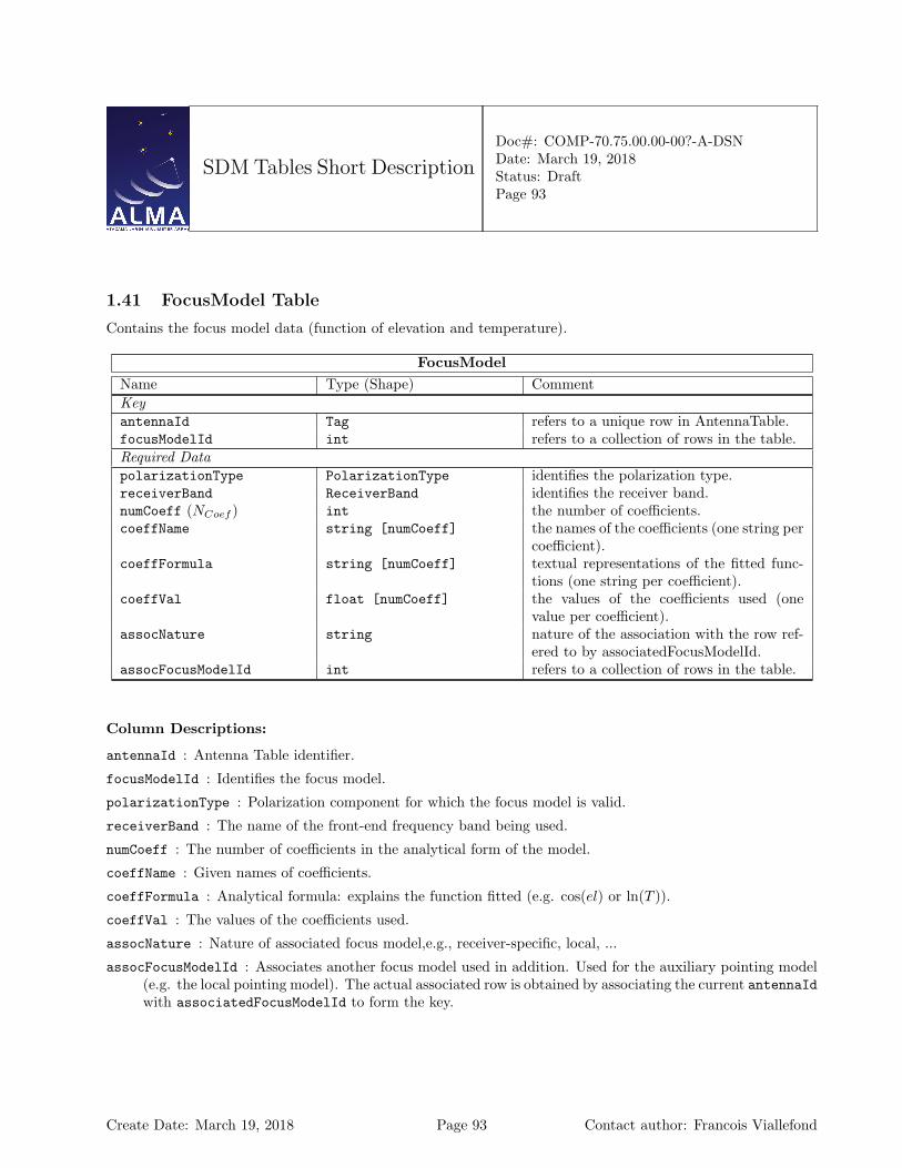
SDM Tables Short Description
Doc#: COMP-70.75.00.00-00?-A-DSNDate: March 19, 2018Status: DraftPage 93
1.41 FocusModel Table
Contains the focus model data (function of elevation and temperature).
FocusModelName Type (Shape) CommentKeyantennaId Tag refers to a unique row in AntennaTable.focusModelId int refers to a collection of rows in the table.Required DatapolarizationType PolarizationType identifies the polarization type.receiverBand ReceiverBand identifies the receiver band.numCoeff (NCoef ) int the number of coefficients.coeffName string [numCoeff] the names of the coefficients (one string per
coefficient).coeffFormula string [numCoeff] textual representations of the fitted func-
tions (one string per coefficient).coeffVal float [numCoeff] the values of the coefficients used (one
value per coefficient).assocNature string nature of the association with the row ref-
ered to by associatedFocusModelId.assocFocusModelId int refers to a collection of rows in the table.
Column Descriptions:
antennaId : Antenna Table identifier.
focusModelId : Identifies the focus model.
polarizationType : Polarization component for which the focus model is valid.
receiverBand : The name of the front-end frequency band being used.
numCoeff : The number of coefficients in the analytical form of the model.
coeffName : Given names of coefficients.
coeffFormula : Analytical formula: explains the function fitted (e.g. cos(el) or ln(T )).
coeffVal : The values of the coefficients used.
assocNature : Nature of associated focus model,e.g., receiver-specific, local, ...
assocFocusModelId : Associates another focus model used in addition. Used for the auxiliary pointing model(e.g. the local pointing model). The actual associated row is obtained by associating the current antennaIdwith associatedFocusModelId to form the key.
Create Date: March 19, 2018 Page 93 Contact author: Francois Viallefond

SDM Tables Short Description
Doc#: COMP-70.75.00.00-00?-A-DSNDate: March 19, 2018Status: DraftPage 94
1.42 FreqOffset Table
Frequency offset information. Contains an additional antenna-based frequency offset relative to the frequenciesin the Spectral Windows. Useful for such thing as Doppler tracking.
FreqOffsetName Type (Shape) CommentKeyantennaId Tag refers to a unique row in AntennaTable.spectralWindowId Tag refers to a unique row in SpectralWin-
dowTable.timeInterval ArrayTimeInterval the time interval of validity of the row’s
content.feedId int refers to a collection of rows in FeedTable.Required Dataoffset Frequency frequency offset.
Column Descriptions:
antennaId : Antenna Table identifier.
spectralWindowId : SpectralWindow Table identifier.
timeInterval : Time Interval of validity of the frequency offset information.
feedId : Specifies which feed was used in the Feed Table.
offset : Frequency offset to be added to the frequency set in the spectral window Table.
Create Date: March 19, 2018 Page 94 Contact author: Francois Viallefond

SDM Tables Short Description
Doc#: COMP-70.75.00.00-00?-A-DSNDate: March 19, 2018Status: DraftPage 95
1.43 GainTracking Table
Gain tracking information. Contains variable control parameters affecting the signal coming from a receiver inan antenna.
GainTrackingName Type (Shape) CommentKeyantennaId Tag refers to a unique row in AntennaTable.spectralWindowId Tag refers to a unique row in SpectralWin-
dowTable.timeInterval ArrayTimeInterval time interval for which the row’s content is
valid.feedId int refers to a unique row in Feed TableRequired DatanumReceptor (NRece) int the number of receptors.attenuator float [numReceptor] the nominal value of the attenuator (one
value per receptor).polarizationType PolarizationType
[numReceptor]describes the polarizations of the receptors(one value per receptor).
Optional DatasamplingLevel float the sampling level.numAttFreq (NAttF ) int the sizes of attSpectrum and attFreq.attFreq double [numAttFreq] the attenuator frequencies.attSpectrum Complex [numAttFreq] the attenuator’s measured spectrum.
Column Descriptions:
antennaId : Antenna Table identifier.
spectralWindowId : SpectralWindow Table identifier.
timeInterval : Time Interval of validity of the feed information.
feedId : Specifies which feed was used in the Feed Table.
numReceptor : The number of receptors.
attenuator : Gain due to the hardware attenuation selected for the Spectral window in this antenna. This isthe nominal value of the attenuator.
polarizationType : The polarization types of the receptors being used.
samplingLevel : Correlator sampling level. Cannot change for ALMA...
numAttFreq : Number of frequency points in attSpectrum
attFreq : Frequencies for the values in attSpectrum.
attSpectrum : Gain due to the hardware attenuation selected for the Spectral window in this antenna. Thisis the actual calibrated spectrum measured in the lab (complex values) as a function of frequency.
Create Date: March 19, 2018 Page 95 Contact author: Francois Viallefond
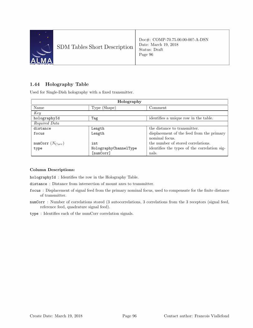
SDM Tables Short Description
Doc#: COMP-70.75.00.00-00?-A-DSNDate: March 19, 2018Status: DraftPage 96
1.44 Holography Table
Used for Single-Dish holography with a fixed transmitter.
HolographyName Type (Shape) CommentKeyholographyId Tag identifies a unique row in the table.Required Datadistance Length the distance to transmitter.focus Length displacement of the feed from the primary
nominal focus.numCorr (NCorr) int the number of stored correlations.type HolographyChannelType
[numCorr]identifies the types of the correlation sig-nals.
Column Descriptions:
holographyId : Identifies the row in the Holography Table.
distance : Distance from intersection of mount axes to transmitter.
focus : Displacement of signal feed from the primary nominal focus, used to compensate for the finite distanceof transmitter.
numCorr : Number of correlations stored (3 autocorrelations, 3 correlations from the 3 receptors (signal feed,reference feed, quadrature signal feed).
type : Identifies each of the numCorr correlation signals.
Create Date: March 19, 2018 Page 96 Contact author: Francois Viallefond
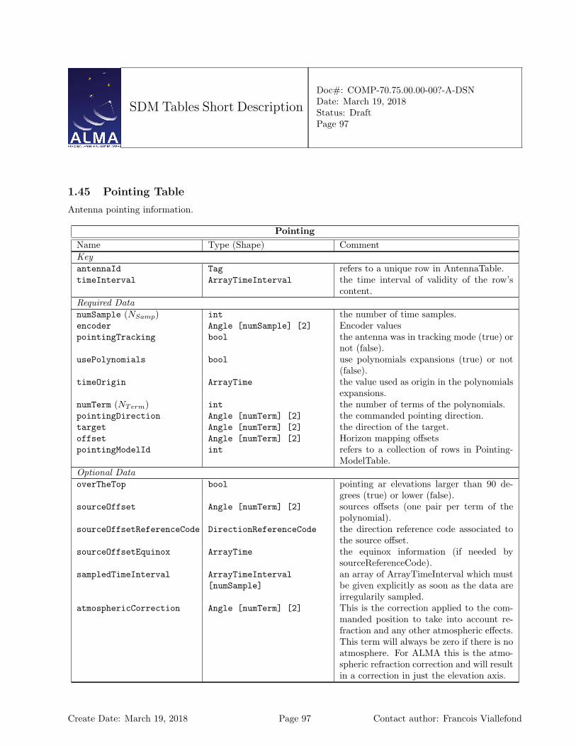
SDM Tables Short Description
Doc#: COMP-70.75.00.00-00?-A-DSNDate: March 19, 2018Status: DraftPage 97
1.45 Pointing Table
Antenna pointing information.
PointingName Type (Shape) CommentKeyantennaId Tag refers to a unique row in AntennaTable.timeInterval ArrayTimeInterval the time interval of validity of the row’s
content.Required DatanumSample (NSamp) int the number of time samples.encoder Angle [numSample] [2] Encoder valuespointingTracking bool the antenna was in tracking mode (true) or
not (false).usePolynomials bool use polynomials expansions (true) or not
(false).timeOrigin ArrayTime the value used as origin in the polynomials
expansions.numTerm (NTerm) int the number of terms of the polynomials.pointingDirection Angle [numTerm] [2] the commanded pointing direction.target Angle [numTerm] [2] the direction of the target.offset Angle [numTerm] [2] Horizon mapping offsetspointingModelId int refers to a collection of rows in Pointing-
ModelTable.Optional DataoverTheTop bool pointing ar elevations larger than 90 de-
grees (true) or lower (false).sourceOffset Angle [numTerm] [2] sources offsets (one pair per term of the
polynomial).sourceOffsetReferenceCode DirectionReferenceCode the direction reference code associated to
the source offset.sourceOffsetEquinox ArrayTime the equinox information (if needed by
sourceReferenceCode).sampledTimeInterval ArrayTimeInterval
[numSample]an array of ArrayTimeInterval which mustbe given explicitly as soon as the data areirregularily sampled.
atmosphericCorrection Angle [numTerm] [2] This is the correction applied to the com-manded position to take into account re-fraction and any other atmospheric effects.This term will always be zero if there is noatmosphere. For ALMA this is the atmo-spheric refraction correction and will resultin a correction in just the elevation axis.
Create Date: March 19, 2018 Page 97 Contact author: Francois Viallefond
SDM Tables Short Description
Doc#: COMP-70.75.00.00-00?-A-DSNDate: March 19, 2018Status: DraftPage 98
Column Descriptions:
antennaId : Antenna Table identifier.
timeInterval : Time Interval of validity of the feed information.
numSample : The number of time samples for encoder. The sampling intervals divide timeInterval intoNSamp contiguous intervals of equal duration. This is also used for the other direction columns (offset,pointingDirection, target, sourceOffset) when usePolynomials is false: in that case NTerm=NSamp.
encoder : The values measured from the antenna. They may be however affected by metrology, if applied. Notethat for ALMA this column will contain positions obtained using the AZ POSN RSP and EL POSN RSPmonitor points of the ACU and not the GET AZ ENC and GET EL ENC monitor points (as these do notinclude the metrology corrections). It is agreed that the the vendor pointing model will never be applied.AZELNOWAntenna.position
pointingTracking : Indicates that the antenna is in tracking mode.
usePolynomials : See numSample and numTerm.
timeOrigin : The time origin for polynomial expansions of pointingDirection, target, offset, andsourceOffset. Equal to the midpoint of timeInterval if NTerm=1.
numTerm :
– If usePolynomials is false: NTerm= NSamp, and the values in the direction columns (offset,pointingDirection, target, sourceOffset) correspond to the same sampling intervals used forencoder.
– If usePolynomials is true: NTermis the number of terms in the polynomial expansion for thedirection columns (offset, pointingDirection, target, sourceOffset) . The time origin for thesepolynomials is timeOrigin.
pointingDirection : This is the commanded direction of the antenna. It is obtained by adding the targetand offset columns, and then applying the pointing model referenced by PointingModelId. The pointingmodel can be the composition of the absolute pointing model and of a local pointing model. In that casetheir coefficients will both be in the PointingModel table.
target : This is the field center direction (as given in the Field Table), possibly affected by the optionalantenna-based sourceOffset. This column is in horizontal coordinates. AZELNOWAntenna.position
offset : Additional offsets in horizontal coordinates (usually meant for measuring the pointing corrections,mapping the antenna beam, ...). AZELNOWAntenna.positiontarget
pointingModelId : Link to the pointing model applied.
overTheTop : The antenna is pointing at elevations larger than 90 degrees. Deprecated for ALMA, should nothappen.
sourceOffset : Optionally, the antenna-based mapping offsets in the field. These are in the equatorial system,and used, for instance, in on-the-fly mapping when the antennas are driven independently across the field.
sourceOffsetReferenceCode : Source offset reference code, defaults to J2000.
sourceOffsetEquinox : Source offset equinox, if needed by sourceOffsetReference.
Create Date: March 19, 2018 Page 98 Contact author: Francois Viallefond

SDM Tables Short Description
Doc#: COMP-70.75.00.00-00?-A-DSNDate: March 19, 2018Status: DraftPage 99
sampledTimeInterval : long doc missing
atmosphericCorrection : long doc missing
Create Date: March 19, 2018 Page 99 Contact author: Francois Viallefond
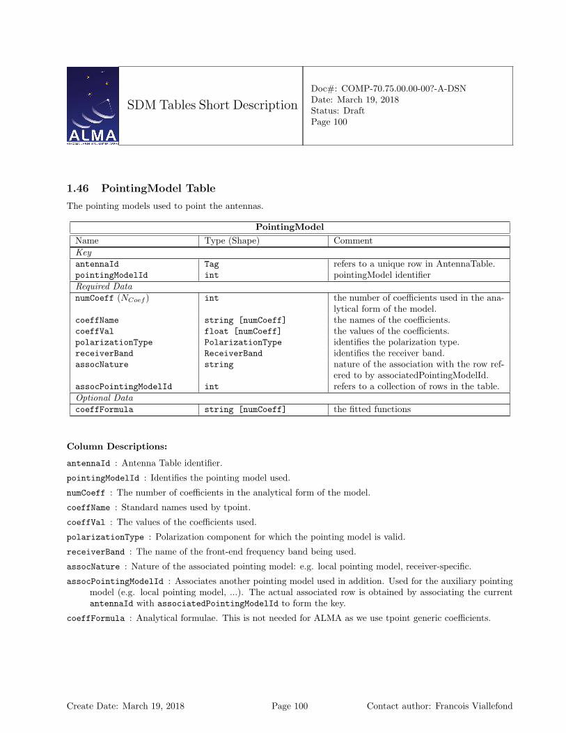
SDM Tables Short Description
Doc#: COMP-70.75.00.00-00?-A-DSNDate: March 19, 2018Status: DraftPage 100
1.46 PointingModel Table
The pointing models used to point the antennas.
PointingModelName Type (Shape) CommentKeyantennaId Tag refers to a unique row in AntennaTable.pointingModelId int pointingModel identifierRequired DatanumCoeff (NCoef ) int the number of coefficients used in the ana-
lytical form of the model.coeffName string [numCoeff] the names of the coefficients.coeffVal float [numCoeff] the values of the coefficients.polarizationType PolarizationType identifies the polarization type.receiverBand ReceiverBand identifies the receiver band.assocNature string nature of the association with the row ref-
ered to by associatedPointingModelId.assocPointingModelId int refers to a collection of rows in the table.Optional DatacoeffFormula string [numCoeff] the fitted functions
Column Descriptions:
antennaId : Antenna Table identifier.
pointingModelId : Identifies the pointing model used.
numCoeff : The number of coefficients in the analytical form of the model.
coeffName : Standard names used by tpoint.
coeffVal : The values of the coefficients used.
polarizationType : Polarization component for which the pointing model is valid.
receiverBand : The name of the front-end frequency band being used.
assocNature : Nature of the associated pointing model: e.g. local pointing model, receiver-specific.
assocPointingModelId : Associates another pointing model used in addition. Used for the auxiliary pointingmodel (e.g. local pointing model, ...). The actual associated row is obtained by associating the currentantennaId with associatedPointingModelId to form the key.
coeffFormula : Analytical formulae. This is not needed for ALMA as we use tpoint generic coefficients.
Create Date: March 19, 2018 Page 100 Contact author: Francois Viallefond
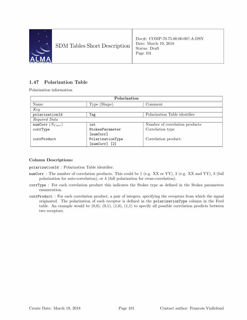
SDM Tables Short Description
Doc#: COMP-70.75.00.00-00?-A-DSNDate: March 19, 2018Status: DraftPage 101
1.47 Polarization Table
Polarization information.
PolarizationName Type (Shape) CommentKeypolarizationId Tag Polarization Table identifierRequired DatanumCorr (NCorr) int Number of correlation productscorrType StokesParameter
[numCorr]Correlation type
corrProduct PolarizationType[numCorr] [2]
Correlation product.
Column Descriptions:
polarizationId : Polarization Table identifier.
numCorr : The number of correlation products. This could be 1 (e.g. XX or YY), 2 (e.g. XX and YY), 3 (fullpolarization for auto-correlation), or 4 (full polarization for cross-correlation).
corrType : For each correlation product this indicates the Stokes type as defined in the Stokes parametersenumeration.
corrProduct : For each correlation product, a pair of integers, specifying the receptors from which the signaloriginated. The polarization of each receptor is defined in the polarizationType column in the Feedtable. An example would be (0,0), (0,1), (1,0), (1,1) to specify all possible correlation prodicts betweentwo receptors.
Create Date: March 19, 2018 Page 101 Contact author: Francois Viallefond

SDM Tables Short Description
Doc#: COMP-70.75.00.00-00?-A-DSNDate: March 19, 2018Status: DraftPage 102
1.48 Processor Table
Processor characteristics. This table holds summary information for the back-end processing devices used togenerate the basic science data.
ProcessorName Type (Shape) CommentKeyprocessorId Tag Processor identifierRequired DatamodeId Tag refers to a unique row in CorrelatorMod-
eTable or SquareLawDetectorTable or Al-maRadiometerTable.
processorType ProcessorType identifies the generic type of the processor.processorSubType ProcessorSubType identifies the type of processor refered to
by modeId.
Column Descriptions:
processorId : Processor Table identifier.
modeId : Processor table identifier.
processorType : The generic type of processor used.
processorSubType : Identifies the SDM table containing the processor-dependent information.
Create Date: March 19, 2018 Page 102 Contact author: Francois Viallefond
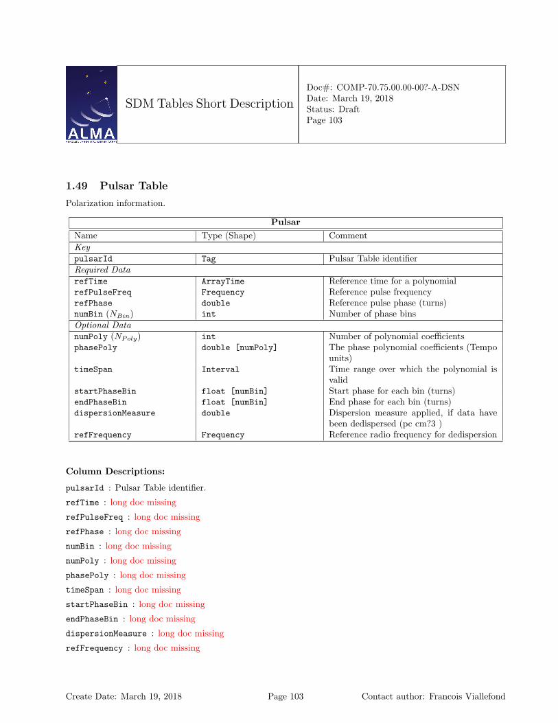
SDM Tables Short Description
Doc#: COMP-70.75.00.00-00?-A-DSNDate: March 19, 2018Status: DraftPage 103
1.49 Pulsar Table
Polarization information.
PulsarName Type (Shape) CommentKeypulsarId Tag Pulsar Table identifierRequired DatarefTime ArrayTime Reference time for a polynomialrefPulseFreq Frequency Reference pulse frequencyrefPhase double Reference pulse phase (turns)numBin (NBin) int Number of phase binsOptional DatanumPoly (NPoly) int Number of polynomial coefficientsphasePoly double [numPoly] The phase polynomial coefficients (Tempo
units)timeSpan Interval Time range over which the polynomial is
validstartPhaseBin float [numBin] Start phase for each bin (turns)endPhaseBin float [numBin] End phase for each bin (turns)dispersionMeasure double Dispersion measure applied, if data have
been dedispersed (pc cm?3 )refFrequency Frequency Reference radio frequency for dedispersion
Column Descriptions:
pulsarId : Pulsar Table identifier.
refTime : long doc missing
refPulseFreq : long doc missing
refPhase : long doc missing
numBin : long doc missing
numPoly : long doc missing
phasePoly : long doc missing
timeSpan : long doc missing
startPhaseBin : long doc missing
endPhaseBin : long doc missing
dispersionMeasure : long doc missing
refFrequency : long doc missing
Create Date: March 19, 2018 Page 103 Contact author: Francois Viallefond
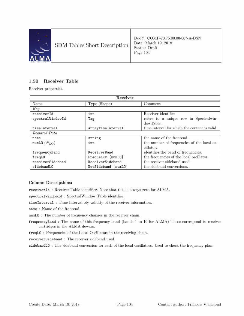
SDM Tables Short Description
Doc#: COMP-70.75.00.00-00?-A-DSNDate: March 19, 2018Status: DraftPage 104
1.50 Receiver Table
Receiver properties.
ReceiverName Type (Shape) CommentKeyreceiverId int Receiver identifierspectralWindowId Tag refers to a unique row in Spectralwin-
dowTable.timeInterval ArrayTimeInterval time interval for which the content is valid.Required Dataname string the name of the frontend.numLO (NLO) int the number of frequencies of the local os-
cillator.frequencyBand ReceiverBand identifies the band of frequencies.freqLO Frequency [numLO] the frequencies of the local oscillator.receiverSideband ReceiverSideband the receiver sideband used.sidebandLO NetSideband [numLO] the sideband conversions.
Column Descriptions:
receiverId : Receiver Table identifier. Note that this is always zero for ALMA.
spectralWindowId : SpectralWindow Table identifier.
timeInterval : Time Interval ofy validity of the receiver information.
name : Name of the frontend.
numLO : The number of frequency changes in the receiver chain.
frequencyBand : The name of this frequency band (bands 1 to 10 for ALMA) These correspond to receivercartridges in the ALMA dewars.
freqLO : Frequencies of the Local Oscillators in the receiving chain.
receiverSideband : The receiver sideband used.
sidebandLO : The sideband conversion for each of the local oscillators. Used to check the frequency plan.
Create Date: March 19, 2018 Page 104 Contact author: Francois Viallefond
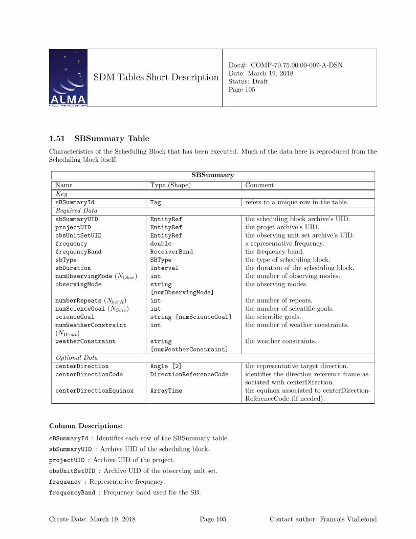
SDM Tables Short Description
Doc#: COMP-70.75.00.00-00?-A-DSNDate: March 19, 2018Status: DraftPage 105
1.51 SBSummary Table
Characteristics of the Scheduling Block that has been executed. Much of the data here is reproduced from theScheduling block itself.
SBSummaryName Type (Shape) CommentKeysBSummaryId Tag refers to a unique row in the table.Required DatasbSummaryUID EntityRef the scheduling block archive’s UID.projectUID EntityRef the projet archive’s UID.obsUnitSetUID EntityRef the observing unit set archive’s UID.frequency double a representative frequency.frequencyBand ReceiverBand the frequency band.sbType SBType the type of scheduling block.sbDuration Interval the duration of the scheduling block.numObservingMode (NObse) int the number of observing modes.observingMode string
[numObservingMode]the observing modes.
numberRepeats (NberR) int the number of repeats.numScienceGoal (NScie) int the number of scientific goals.scienceGoal string [numScienceGoal] the scientific goals.numWeatherConstraint(NWeat)
int the number of weather constraints.
weatherConstraint string[numWeatherConstraint]
the weather constraints.
Optional DatacenterDirection Angle [2] the representative target direction.centerDirectionCode DirectionReferenceCode identifies the direction reference frame as-
sociated with centerDirection.centerDirectionEquinox ArrayTime the equinox associated to centerDirection-
ReferenceCode (if needed).
Column Descriptions:
sBSummaryId : Identifies each row of the SBSummary table.
sbSummaryUID : Archive UID of the scheduling block.
projectUID : Archive UID of the project.
obsUnitSetUID : Archive UID of the observing unit set.
frequency : Representative frequency.
frequencyBand : Frequency band used for the SB.
Create Date: March 19, 2018 Page 105 Contact author: Francois Viallefond

SDM Tables Short Description
Doc#: COMP-70.75.00.00-00?-A-DSNDate: March 19, 2018Status: DraftPage 106
sbType : Type of Scheduling Block (e.g. science, calibration, ...)
sbDuration : The duration of this SB (as planned).
numObservingMode : The number of observing modes.
observingMode : Standard observing mode, e.g. singleField, mosaic. One SB cannot have more than onestandard observing mode. Examples: Single Field Interferometry, Pointed Mosaic, ...
numberRepeats : Number of executions scheduled for this SB.
numScienceGoal : Number of science goals.
scienceGoal : The science goals.
numWeatherConstraint : The number of weather constraints.
weatherConstraint : Weather scheduling constraints, as specified in the Observing Tool.
centerDirection : Direction of the representative target.
centerDirectionCode : The center direction reference code, if not J2000.
centerDirectionEquinox : The center direction reference equinox, if required by centerDirectionCode.
Create Date: March 19, 2018 Page 106 Contact author: Francois Viallefond
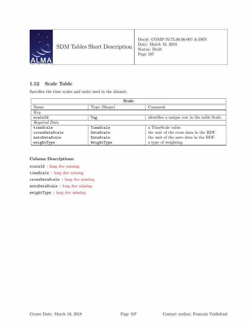
SDM Tables Short Description
Doc#: COMP-70.75.00.00-00?-A-DSNDate: March 19, 2018Status: DraftPage 107
1.52 Scale Table
Specifies the time scales and units used in the dataset.
ScaleName Type (Shape) CommentKeyscaleId Tag identifies a unique row in the table Scale.Required DatatimeScale TimeScale a TimeScale value.crossDataScale DataScale the unit of the cross data in the BDF.autoDataScale DataScale the unit of the auto data in the BDF.weightType WeightType a type of weighting.
Column Descriptions:
scaleId : long doc missing
timeScale : long doc missing
crossDataScale : long doc missing
autoDataScale : long doc missing
weightType : long doc missing
Create Date: March 19, 2018 Page 107 Contact author: Francois Viallefond
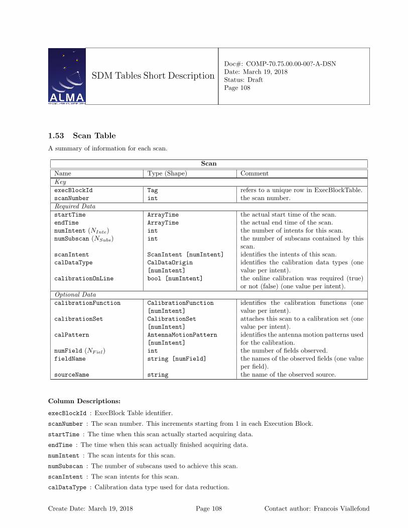
SDM Tables Short Description
Doc#: COMP-70.75.00.00-00?-A-DSNDate: March 19, 2018Status: DraftPage 108
1.53 Scan Table
A summary of information for each scan.
ScanName Type (Shape) CommentKeyexecBlockId Tag refers to a unique row in ExecBlockTable.scanNumber int the scan number.Required DatastartTime ArrayTime the actual start time of the scan.endTime ArrayTime the actual end time of the scan.numIntent (NInte) int the number of intents for this scan.numSubscan (NSubs) int the number of subscans contained by this
scan.scanIntent ScanIntent [numIntent] identifies the intents of this scan.calDataType CalDataOrigin
[numIntent]identifies the calibration data types (onevalue per intent).
calibrationOnLine bool [numIntent] the online calibration was required (true)or not (false) (one value per intent).
Optional DatacalibrationFunction CalibrationFunction
[numIntent]identifies the calibration functions (onevalue per intent).
calibrationSet CalibrationSet[numIntent]
attaches this scan to a calibration set (onevalue per intent).
calPattern AntennaMotionPattern[numIntent]
identifies the antenna motion patterns usedfor the calibration.
numField (NFiel) int the number of fields observed.fieldName string [numField] the names of the observed fields (one value
per field).sourceName string the name of the observed source.
Column Descriptions:
execBlockId : ExecBlock Table identifier.
scanNumber : The scan number. This increments starting from 1 in each Execution Block.
startTime : The time when this scan actually started acquiring data.
endTime : The time when this scan actually finished acquiring data.
numIntent : The scan intents for this scan.
numSubscan : The number of subscans used to achieve this scan.
scanIntent : The scan intents for this scan.
calDataType : Calibration data type used for data reduction.
Create Date: March 19, 2018 Page 108 Contact author: Francois Viallefond

SDM Tables Short Description
Doc#: COMP-70.75.00.00-00?-A-DSNDate: March 19, 2018Status: DraftPage 109
calibrationOnLine : True if on-line calibration was required.
calibrationFunction : Function of the scan in the calibration set. This is used in on-line calibration.
calibrationSet : Identifies that the scan is part of a set of scans aimed at a particular calibration.
calPattern : Identifies the antenna motion pattern used for calibration; data reduction may used this infor-mation.
numField : The number of fields observed during this scan.
fieldName : The names of of the fields observed during this scan.
sourceName : The name of the source observed (optional).
Create Date: March 19, 2018 Page 109 Contact author: Francois Viallefond

SDM Tables Short Description
Doc#: COMP-70.75.00.00-00?-A-DSNDate: March 19, 2018Status: DraftPage 110
1.54 Source Table
Summary of astromomical source information.
SourceName Type (Shape) CommentKeysourceId int identifies a collection of rows in the table.timeInterval ArrayTimeInterval the time interval of validity of the row’s
content.spectralWindowId Tag refers to a unique row in SpectralWin-
dowTable.Required Datacode string indicates the nature of the source.direction Angle [2] the direction of the source.properMotion AngularRate [2] the proper motion of the source.sourceName string the name of the source.Optional DatadirectionCode DirectionReferenceCode identifies the direction reference frame as-
sociated to direction.directionEquinox ArrayTime the equinox associated to the direction ref-
erence frame (if required).calibrationGroup int the calibration group number.catalog string the name of the catalog.deltaVel Speed the velocity resolution.position Length [3] the position of the source.numLines (NLine) int the number of line transitions.transition string [numLines] the names of the transitions.restFrequency Frequency [numLines] the rest frequencies (one value per transi-
tion line).sysVel Speed [numLines] the systemic velocity.rangeVel Speed [2] the velocity range.sourceModel SourceModel identifies the source model.frequencyRefCode FrequencyReferenceCode the frequency reference code.numFreq (NFreq) int the number of frequencies.numStokes (NStok) int the number of Stokes parameters.frequency Frequency [numFreq] the array of frequencies (one value per fre-
quency).frequencyInterval Frequency [numFreq] an array of frequency intervals (one value
per interval).stokesParameter StokesParameter
[numStokes]the array of Stokes parameters (one valueper parameter).
flux Flux [numFreq][numStokes]
the array of flux densities expressed in Jan-sky (Jy).
Create Date: March 19, 2018 Page 110 Contact author: Francois Viallefond
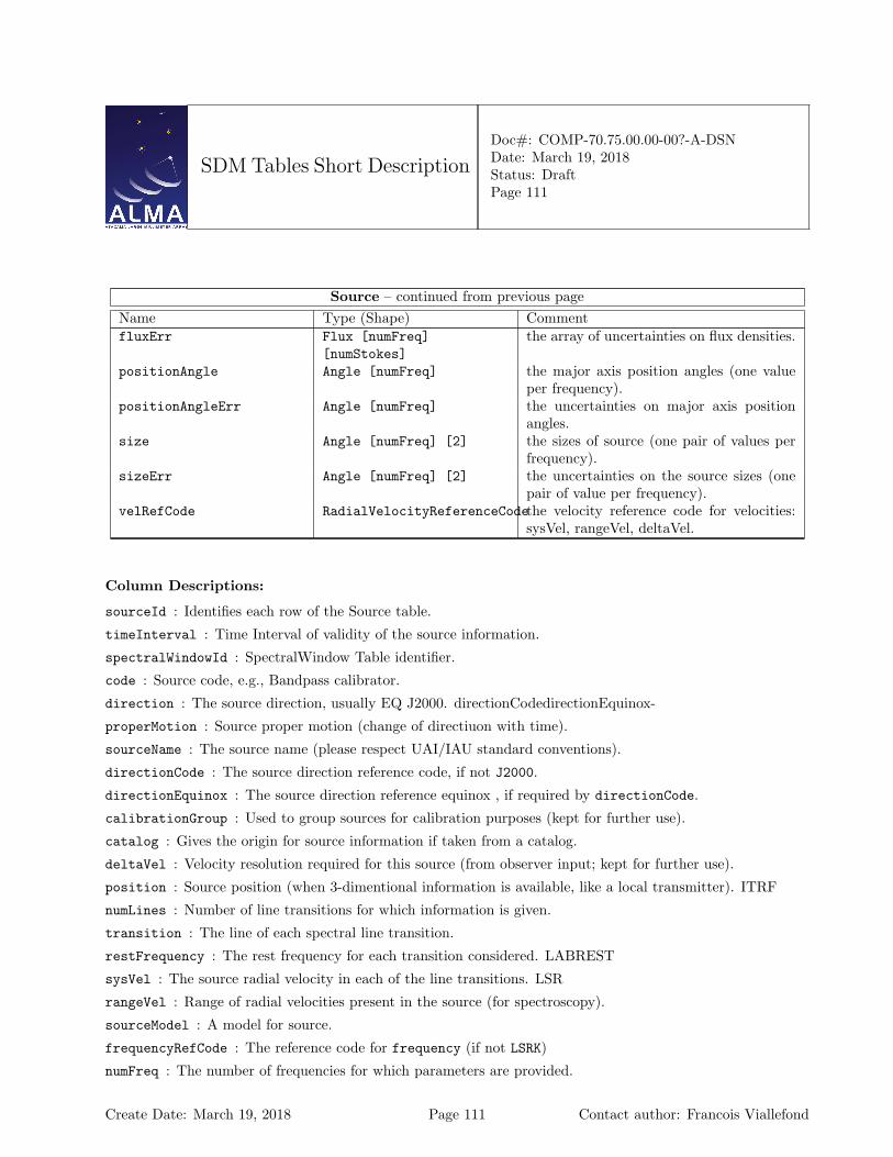
SDM Tables Short Description
Doc#: COMP-70.75.00.00-00?-A-DSNDate: March 19, 2018Status: DraftPage 111
Source – continued from previous pageName Type (Shape) CommentfluxErr Flux [numFreq]
[numStokes]the array of uncertainties on flux densities.
positionAngle Angle [numFreq] the major axis position angles (one valueper frequency).
positionAngleErr Angle [numFreq] the uncertainties on major axis positionangles.
size Angle [numFreq] [2] the sizes of source (one pair of values perfrequency).
sizeErr Angle [numFreq] [2] the uncertainties on the source sizes (onepair of value per frequency).
velRefCode RadialVelocityReferenceCodethe velocity reference code for velocities:sysVel, rangeVel, deltaVel.
Column Descriptions:
sourceId : Identifies each row of the Source table.
timeInterval : Time Interval of validity of the source information.
spectralWindowId : SpectralWindow Table identifier.
code : Source code, e.g., Bandpass calibrator.
direction : The source direction, usually EQ J2000. directionCodedirectionEquinox-
properMotion : Source proper motion (change of directiuon with time).
sourceName : The source name (please respect UAI/IAU standard conventions).
directionCode : The source direction reference code, if not J2000.
directionEquinox : The source direction reference equinox , if required by directionCode.
calibrationGroup : Used to group sources for calibration purposes (kept for further use).
catalog : Gives the origin for source information if taken from a catalog.
deltaVel : Velocity resolution required for this source (from observer input; kept for further use).
position : Source position (when 3-dimentional information is available, like a local transmitter). ITRF
numLines : Number of line transitions for which information is given.
transition : The line of each spectral line transition.
restFrequency : The rest frequency for each transition considered. LABREST
sysVel : The source radial velocity in each of the line transitions. LSR
rangeVel : Range of radial velocities present in the source (for spectroscopy).
sourceModel : A model for source.
frequencyRefCode : The reference code for frequency (if not LSRK)
numFreq : The number of frequencies for which parameters are provided.
Create Date: March 19, 2018 Page 111 Contact author: Francois Viallefond

SDM Tables Short Description
Doc#: COMP-70.75.00.00-00?-A-DSNDate: March 19, 2018Status: DraftPage 112
numStokes : The number of Stokes parameters that are provided at each freqeuncy.
frequency : The list of frequencies for the flux densities LSRK
frequencyInterval : The list of frequency intervals over which flux densities were measured.
stokesParameter : The array of Stokes parameters (one value per parameter).
flux : The values of fluxes provided in Jansky (Jy).
fluxErr : The statistical uncertainties on the fluxes.
positionAngle : Position angles of the major axes for the elliptical sources.
positionAngleErr : Statistical uncertainties for the major axis position angles.
size : Source sizes measured along the major and minor axis.
sizeErr : Statistical uncertainties on the source sizes.
velRefCode : long doc missing
Create Date: March 19, 2018 Page 112 Contact author: Francois Viallefond
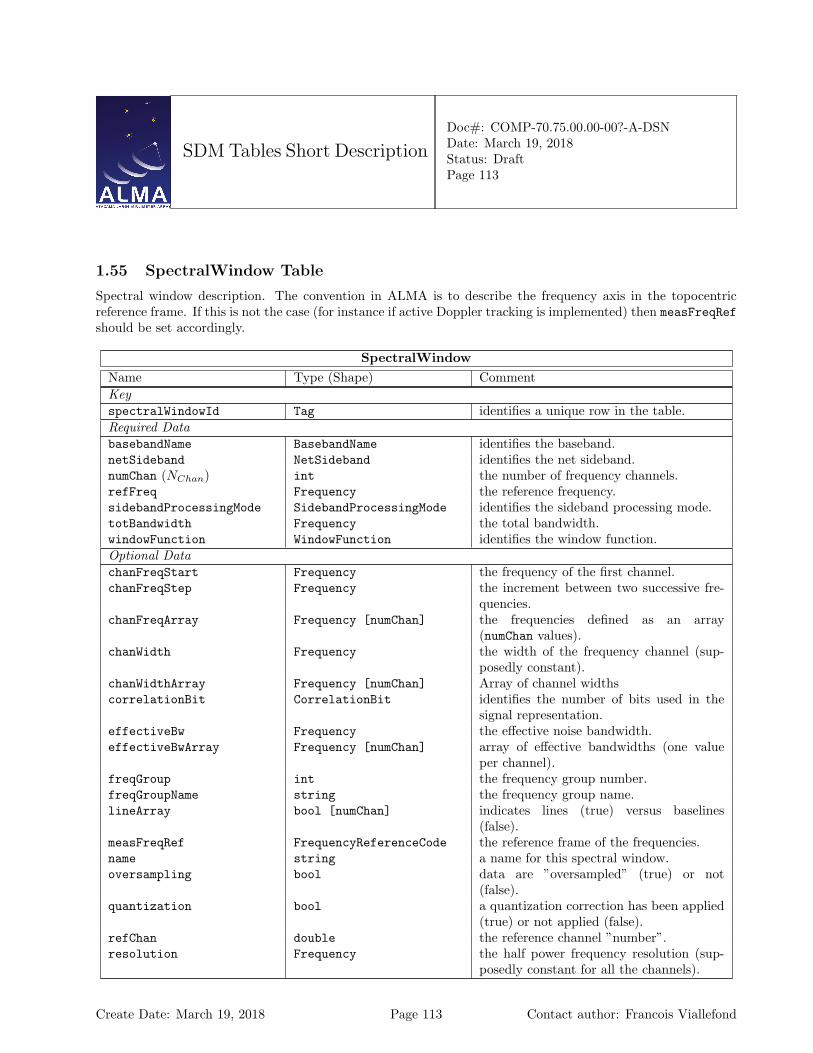
SDM Tables Short Description
Doc#: COMP-70.75.00.00-00?-A-DSNDate: March 19, 2018Status: DraftPage 113
1.55 SpectralWindow Table
Spectral window description. The convention in ALMA is to describe the frequency axis in the topocentricreference frame. If this is not the case (for instance if active Doppler tracking is implemented) then measFreqRefshould be set accordingly.
SpectralWindowName Type (Shape) CommentKeyspectralWindowId Tag identifies a unique row in the table.Required DatabasebandName BasebandName identifies the baseband.netSideband NetSideband identifies the net sideband.numChan (NChan) int the number of frequency channels.refFreq Frequency the reference frequency.sidebandProcessingMode SidebandProcessingMode identifies the sideband processing mode.totBandwidth Frequency the total bandwidth.windowFunction WindowFunction identifies the window function.Optional DatachanFreqStart Frequency the frequency of the first channel.chanFreqStep Frequency the increment between two successive fre-
quencies.chanFreqArray Frequency [numChan] the frequencies defined as an array
(numChan values).chanWidth Frequency the width of the frequency channel (sup-
posedly constant).chanWidthArray Frequency [numChan] Array of channel widthscorrelationBit CorrelationBit identifies the number of bits used in the
signal representation.effectiveBw Frequency the effective noise bandwidth.effectiveBwArray Frequency [numChan] array of effective bandwidths (one value
per channel).freqGroup int the frequency group number.freqGroupName string the frequency group name.lineArray bool [numChan] indicates lines (true) versus baselines
(false).measFreqRef FrequencyReferenceCode the reference frame of the frequencies.name string a name for this spectral window.oversampling bool data are ”oversampled” (true) or not
(false).quantization bool a quantization correction has been applied
(true) or not applied (false).refChan double the reference channel ”number”.resolution Frequency the half power frequency resolution (sup-
posedly constant for all the channels).
Create Date: March 19, 2018 Page 113 Contact author: Francois Viallefond
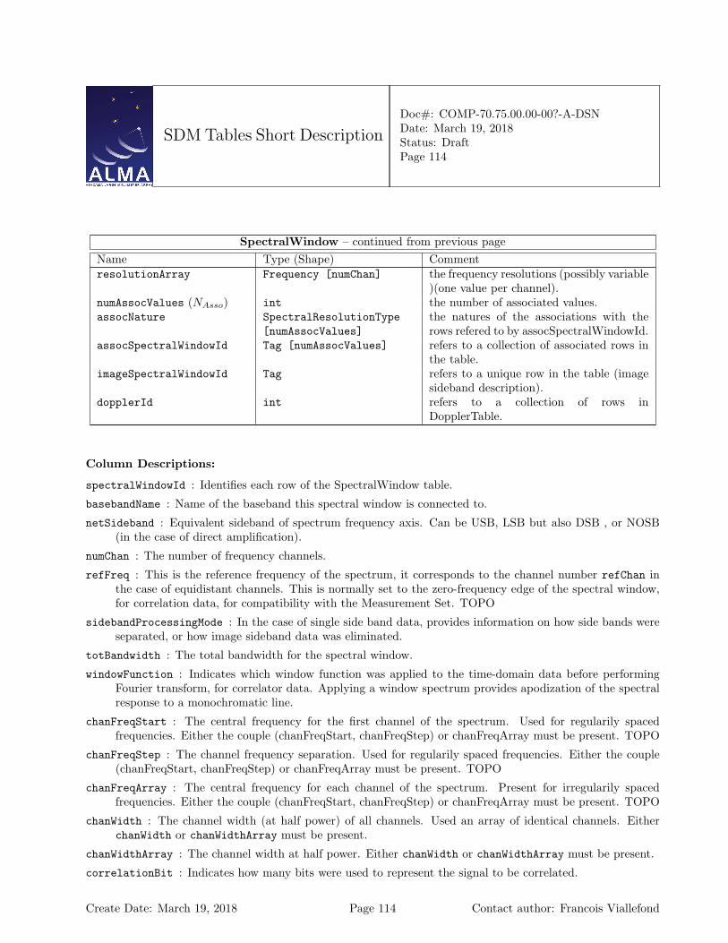
SDM Tables Short Description
Doc#: COMP-70.75.00.00-00?-A-DSNDate: March 19, 2018Status: DraftPage 114
SpectralWindow – continued from previous pageName Type (Shape) CommentresolutionArray Frequency [numChan] the frequency resolutions (possibly variable
)(one value per channel).numAssocValues (NAsso) int the number of associated values.assocNature SpectralResolutionType
[numAssocValues]the natures of the associations with therows refered to by assocSpectralWindowId.
assocSpectralWindowId Tag [numAssocValues] refers to a collection of associated rows inthe table.
imageSpectralWindowId Tag refers to a unique row in the table (imagesideband description).
dopplerId int refers to a collection of rows inDopplerTable.
Column Descriptions:
spectralWindowId : Identifies each row of the SpectralWindow table.
basebandName : Name of the baseband this spectral window is connected to.
netSideband : Equivalent sideband of spectrum frequency axis. Can be USB, LSB but also DSB , or NOSB(in the case of direct amplification).
numChan : The number of frequency channels.
refFreq : This is the reference frequency of the spectrum, it corresponds to the channel number refChan inthe case of equidistant channels. This is normally set to the zero-frequency edge of the spectral window,for correlation data, for compatibility with the Measurement Set. TOPO
sidebandProcessingMode : In the case of single side band data, provides information on how side bands wereseparated, or how image sideband data was eliminated.
totBandwidth : The total bandwidth for the spectral window.
windowFunction : Indicates which window function was applied to the time-domain data before performingFourier transform, for correlator data. Applying a window spectrum provides apodization of the spectralresponse to a monochromatic line.
chanFreqStart : The central frequency for the first channel of the spectrum. Used for regularily spacedfrequencies. Either the couple (chanFreqStart, chanFreqStep) or chanFreqArray must be present. TOPO
chanFreqStep : The channel frequency separation. Used for regularily spaced frequencies. Either the couple(chanFreqStart, chanFreqStep) or chanFreqArray must be present. TOPO
chanFreqArray : The central frequency for each channel of the spectrum. Present for irregularily spacedfrequencies. Either the couple (chanFreqStart, chanFreqStep) or chanFreqArray must be present. TOPO
chanWidth : The channel width (at half power) of all channels. Used an array of identical channels. EitherchanWidth or chanWidthArray must be present.
chanWidthArray : The channel width at half power. Either chanWidth or chanWidthArray must be present.
correlationBit : Indicates how many bits were used to represent the signal to be correlated.
Create Date: March 19, 2018 Page 114 Contact author: Francois Viallefond
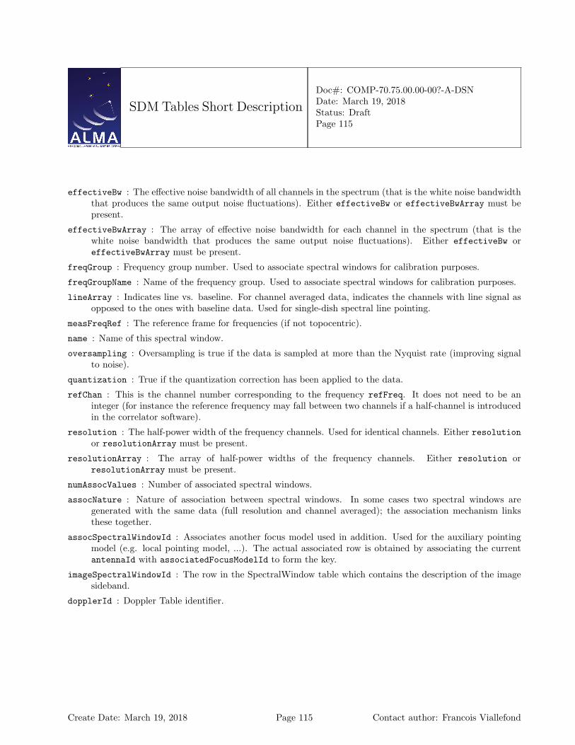
SDM Tables Short Description
Doc#: COMP-70.75.00.00-00?-A-DSNDate: March 19, 2018Status: DraftPage 115
effectiveBw : The effective noise bandwidth of all channels in the spectrum (that is the white noise bandwidththat produces the same output noise fluctuations). Either effectiveBw or effectiveBwArray must bepresent.
effectiveBwArray : The array of effective noise bandwidth for each channel in the spectrum (that is thewhite noise bandwidth that produces the same output noise fluctuations). Either effectiveBw oreffectiveBwArray must be present.
freqGroup : Frequency group number. Used to associate spectral windows for calibration purposes.
freqGroupName : Name of the frequency group. Used to associate spectral windows for calibration purposes.
lineArray : Indicates line vs. baseline. For channel averaged data, indicates the channels with line signal asopposed to the ones with baseline data. Used for single-dish spectral line pointing.
measFreqRef : The reference frame for frequencies (if not topocentric).
name : Name of this spectral window.
oversampling : Oversampling is true if the data is sampled at more than the Nyquist rate (improving signalto noise).
quantization : True if the quantization correction has been applied to the data.
refChan : This is the channel number corresponding to the frequency refFreq. It does not need to be aninteger (for instance the reference frequency may fall between two channels if a half-channel is introducedin the correlator software).
resolution : The half-power width of the frequency channels. Used for identical channels. Either resolutionor resolutionArray must be present.
resolutionArray : The array of half-power widths of the frequency channels. Either resolution orresolutionArray must be present.
numAssocValues : Number of associated spectral windows.
assocNature : Nature of association between spectral windows. In some cases two spectral windows aregenerated with the same data (full resolution and channel averaged); the association mechanism linksthese together.
assocSpectralWindowId : Associates another focus model used in addition. Used for the auxiliary pointingmodel (e.g. local pointing model, ...). The actual associated row is obtained by associating the currentantennaId with associatedFocusModelId to form the key.
imageSpectralWindowId : The row in the SpectralWindow table which contains the description of the imagesideband.
dopplerId : Doppler Table identifier.
Create Date: March 19, 2018 Page 115 Contact author: Francois Viallefond
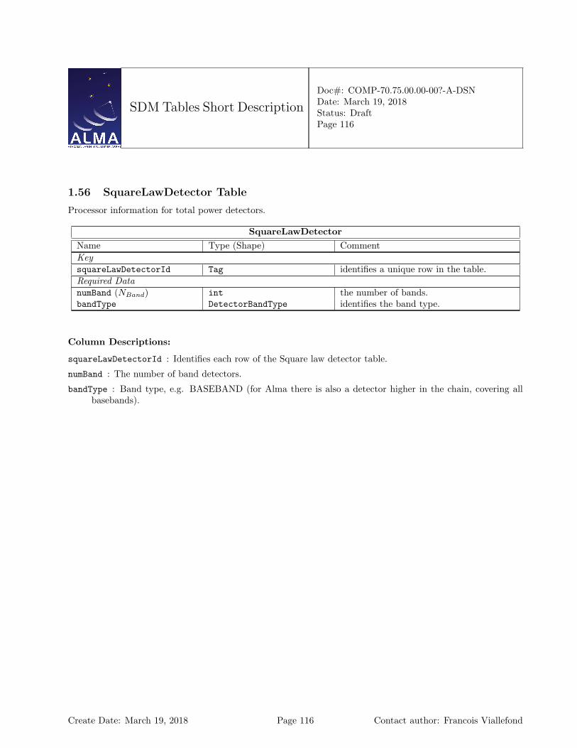
SDM Tables Short Description
Doc#: COMP-70.75.00.00-00?-A-DSNDate: March 19, 2018Status: DraftPage 116
1.56 SquareLawDetector Table
Processor information for total power detectors.
SquareLawDetectorName Type (Shape) CommentKeysquareLawDetectorId Tag identifies a unique row in the table.Required DatanumBand (NBand) int the number of bands.bandType DetectorBandType identifies the band type.
Column Descriptions:
squareLawDetectorId : Identifies each row of the Square law detector table.
numBand : The number of band detectors.
bandType : Band type, e.g. BASEBAND (for Alma there is also a detector higher in the chain, covering allbasebands).
Create Date: March 19, 2018 Page 116 Contact author: Francois Viallefond
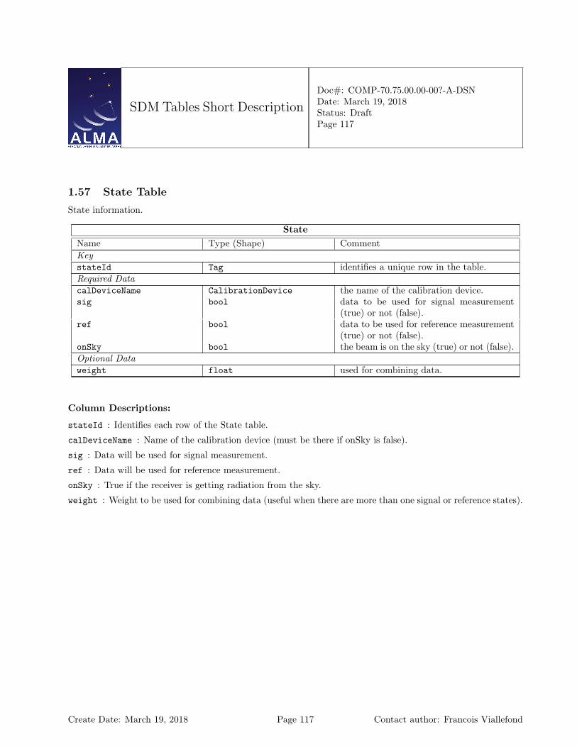
SDM Tables Short Description
Doc#: COMP-70.75.00.00-00?-A-DSNDate: March 19, 2018Status: DraftPage 117
1.57 State Table
State information.
StateName Type (Shape) CommentKeystateId Tag identifies a unique row in the table.Required DatacalDeviceName CalibrationDevice the name of the calibration device.sig bool data to be used for signal measurement
(true) or not (false).ref bool data to be used for reference measurement
(true) or not (false).onSky bool the beam is on the sky (true) or not (false).Optional Dataweight float used for combining data.
Column Descriptions:
stateId : Identifies each row of the State table.
calDeviceName : Name of the calibration device (must be there if onSky is false).
sig : Data will be used for signal measurement.
ref : Data will be used for reference measurement.
onSky : True if the receiver is getting radiation from the sky.
weight : Weight to be used for combining data (useful when there are more than one signal or reference states).
Create Date: March 19, 2018 Page 117 Contact author: Francois Viallefond
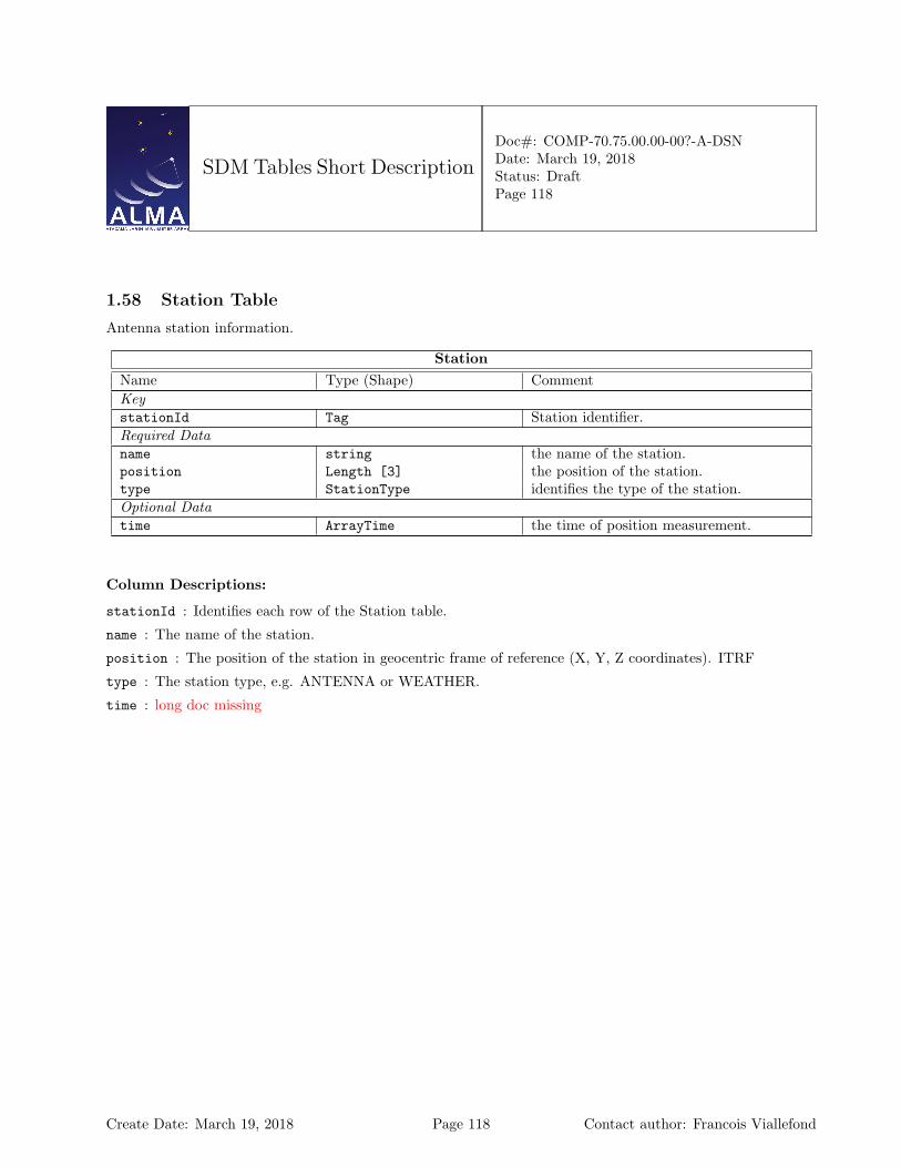
SDM Tables Short Description
Doc#: COMP-70.75.00.00-00?-A-DSNDate: March 19, 2018Status: DraftPage 118
1.58 Station Table
Antenna station information.
StationName Type (Shape) CommentKeystationId Tag Station identifier.Required Dataname string the name of the station.position Length [3] the position of the station.type StationType identifies the type of the station.Optional Datatime ArrayTime the time of position measurement.
Column Descriptions:
stationId : Identifies each row of the Station table.
name : The name of the station.
position : The position of the station in geocentric frame of reference (X, Y, Z coordinates). ITRF
type : The station type, e.g. ANTENNA or WEATHER.
time : long doc missing
Create Date: March 19, 2018 Page 118 Contact author: Francois Viallefond

SDM Tables Short Description
Doc#: COMP-70.75.00.00-00?-A-DSNDate: March 19, 2018Status: DraftPage 119
1.59 Subscan Table
Subscan-based information.
SubscanName Type (Shape) CommentKeyexecBlockId Tag identifies a unique row in ExecBlockTable.scanNumber int the number of the scan this subscan be-
longs to.subscanNumber int the subscan number.Required DatastartTime ArrayTime the actual start time of the subscan.endTime ArrayTime the actual end time of the subscan.fieldName string the name of the observed field.subscanIntent SubscanIntent the intent of the subscan.numIntegration (NInte) int the number of integrations during the scan.numSubintegration (NSubi) int [numIntegration] the number of subintegrations for each in-
tegration.Optional DatasubscanMode SwitchingMode identifies the data acquisition mode during
the subscan.correlatorCalibration CorrelatorCalibration identifies the correlator calibration during
the subscan.
Column Descriptions:
execBlockId : ExecBlock Table identifier.
scanNumber : The scan number. This increments starting from 1 in each Execution Block.
subscanNumber : The subscans in a scan are numbered incrementally starting from 1 in each new scan.
startTime : The time when the subscan started collecting science data.
endTime : The time when the subscan finished collecting science data.
fieldName : The name of the field observed during this subscan.
subscanIntent : The intent for this subscan.
numIntegration : The number of integrations in this subscan.
numSubintegration : The number of sub-integrations in each one of the integrations of this subscan.
subscanMode : Describe the mode in which data was taken. Can be e.g. nutator switching, frequency switching,or no switching.
correlatorCalibration : Indicates whether this subscan is used for correlator internal calibration.
Create Date: March 19, 2018 Page 119 Contact author: Francois Viallefond
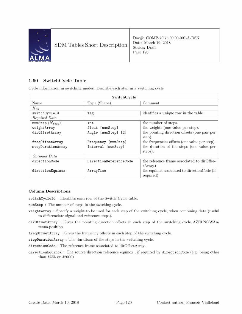
SDM Tables Short Description
Doc#: COMP-70.75.00.00-00?-A-DSNDate: March 19, 2018Status: DraftPage 120
1.60 SwitchCycle Table
Cycle information in switching modes. Describe each step in a switching cycle.
SwitchCycleName Type (Shape) CommentKeyswitchCycleId Tag identifies a unique row in the table.Required DatanumStep (NStep) int the number of steps.weightArray float [numStep] the weights (one value per step).dirOffsetArray Angle [numStep] [2] the pointing direction offsets (one pair per
step).freqOffsetArray Frequency [numStep] the frequencies offsets (one value per step).stepDurationArray Interval [numStep] the duration of the steps (one value per
steps).Optional DatadirectionCode DirectionReferenceCode the reference frame associated to dirOffse-
tArray.tdirectionEquinox ArrayTime the equinox associated to directionCode (if
required).
Column Descriptions:
switchCycleId : Identifies each row of the Switch Cycle table.
numStep : The number of steps in the swtching cycle.
weightArray : Specify a weight to be used for each step of the switching cycle, when combining data (usefulto differenciate signal and reference steps).
dirOffsetArray : Gives the pointing direction offsets in each step of the switching cycle AZELNOWAn-tenna.position
freqOffsetArray : Gives the frequency offsets in each step of the switching cycle.
stepDurationArray : The durations of the steps in the switching cycle.
directionCode : The reference frame associated to dirOffsetArray.
directionEquinox : The source direction reference equinox , if required by directionCode (e.g. being otherthan AZEL or J2000)
Create Date: March 19, 2018 Page 120 Contact author: Francois Viallefond
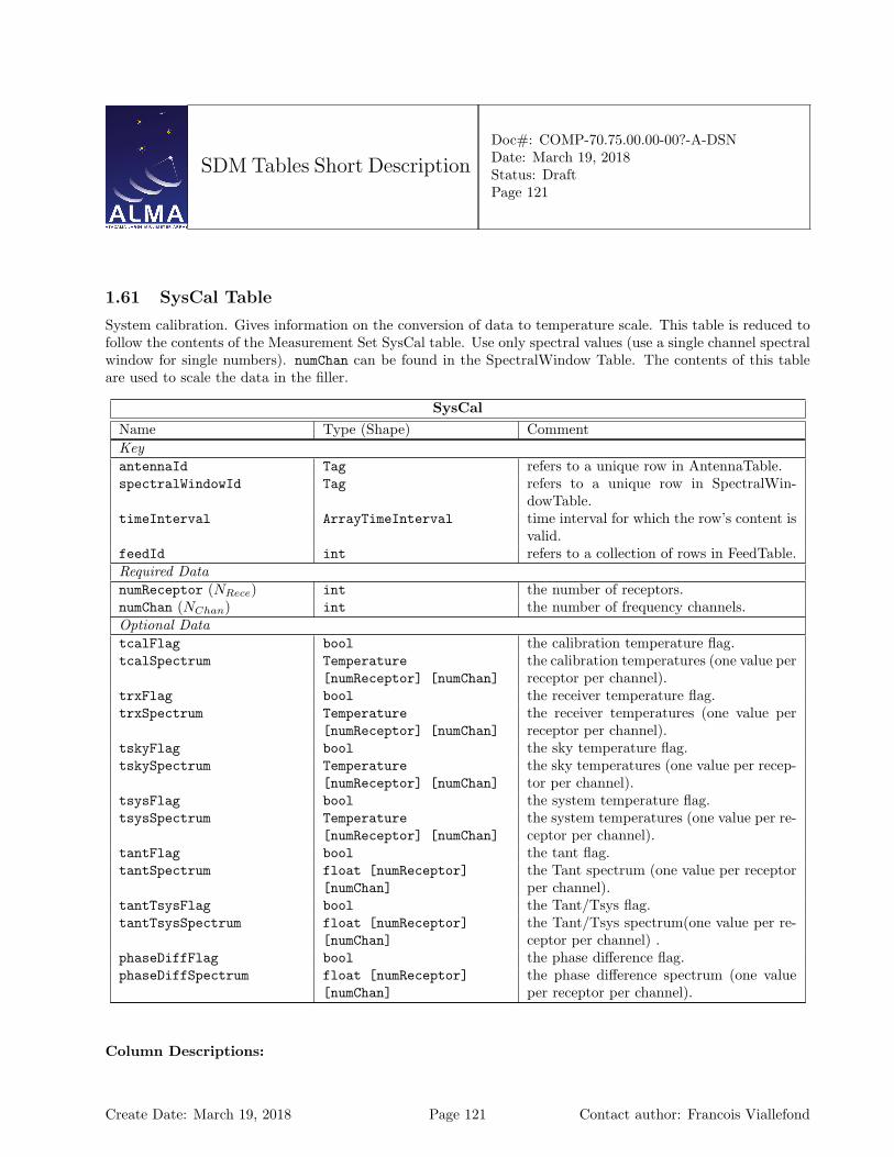
SDM Tables Short Description
Doc#: COMP-70.75.00.00-00?-A-DSNDate: March 19, 2018Status: DraftPage 121
1.61 SysCal Table
System calibration. Gives information on the conversion of data to temperature scale. This table is reduced tofollow the contents of the Measurement Set SysCal table. Use only spectral values (use a single channel spectralwindow for single numbers). numChan can be found in the SpectralWindow Table. The contents of this tableare used to scale the data in the filler.
SysCalName Type (Shape) CommentKeyantennaId Tag refers to a unique row in AntennaTable.spectralWindowId Tag refers to a unique row in SpectralWin-
dowTable.timeInterval ArrayTimeInterval time interval for which the row’s content is
valid.feedId int refers to a collection of rows in FeedTable.Required DatanumReceptor (NRece) int the number of receptors.numChan (NChan) int the number of frequency channels.Optional DatatcalFlag bool the calibration temperature flag.tcalSpectrum Temperature
[numReceptor] [numChan]the calibration temperatures (one value perreceptor per channel).
trxFlag bool the receiver temperature flag.trxSpectrum Temperature
[numReceptor] [numChan]the receiver temperatures (one value perreceptor per channel).
tskyFlag bool the sky temperature flag.tskySpectrum Temperature
[numReceptor] [numChan]the sky temperatures (one value per recep-tor per channel).
tsysFlag bool the system temperature flag.tsysSpectrum Temperature
[numReceptor] [numChan]the system temperatures (one value per re-ceptor per channel).
tantFlag bool the tant flag.tantSpectrum float [numReceptor]
[numChan]the Tant spectrum (one value per receptorper channel).
tantTsysFlag bool the Tant/Tsys flag.tantTsysSpectrum float [numReceptor]
[numChan]the Tant/Tsys spectrum(one value per re-ceptor per channel) .
phaseDiffFlag bool the phase difference flag.phaseDiffSpectrum float [numReceptor]
[numChan]the phase difference spectrum (one valueper receptor per channel).
Column Descriptions:
Create Date: March 19, 2018 Page 121 Contact author: Francois Viallefond
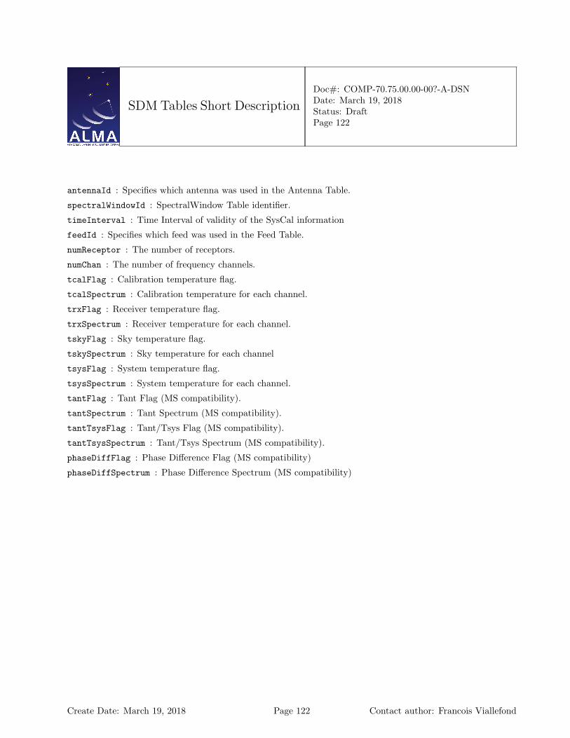
SDM Tables Short Description
Doc#: COMP-70.75.00.00-00?-A-DSNDate: March 19, 2018Status: DraftPage 122
antennaId : Specifies which antenna was used in the Antenna Table.
spectralWindowId : SpectralWindow Table identifier.
timeInterval : Time Interval of validity of the SysCal information
feedId : Specifies which feed was used in the Feed Table.
numReceptor : The number of receptors.
numChan : The number of frequency channels.
tcalFlag : Calibration temperature flag.
tcalSpectrum : Calibration temperature for each channel.
trxFlag : Receiver temperature flag.
trxSpectrum : Receiver temperature for each channel.
tskyFlag : Sky temperature flag.
tskySpectrum : Sky temperature for each channel
tsysFlag : System temperature flag.
tsysSpectrum : System temperature for each channel.
tantFlag : Tant Flag (MS compatibility).
tantSpectrum : Tant Spectrum (MS compatibility).
tantTsysFlag : Tant/Tsys Flag (MS compatibility).
tantTsysSpectrum : Tant/Tsys Spectrum (MS compatibility).
phaseDiffFlag : Phase Difference Flag (MS compatibility)
phaseDiffSpectrum : Phase Difference Spectrum (MS compatibility)
Create Date: March 19, 2018 Page 122 Contact author: Francois Viallefond
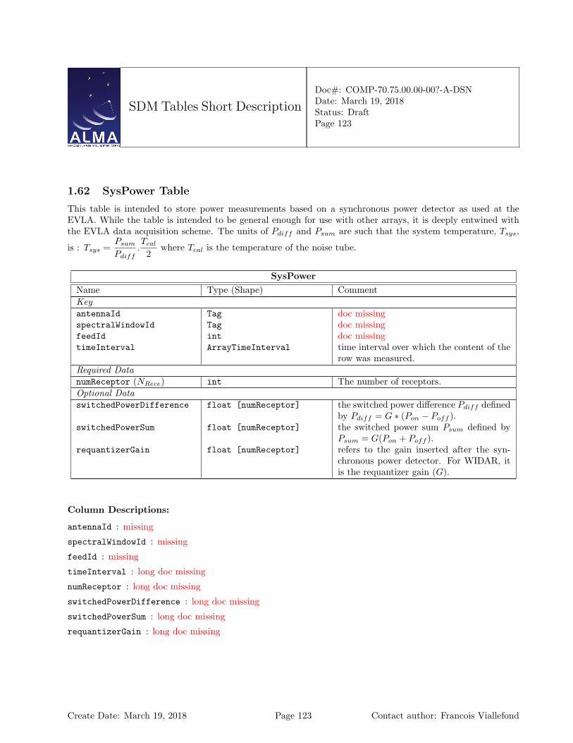
SDM Tables Short Description
Doc#: COMP-70.75.00.00-00?-A-DSNDate: March 19, 2018Status: DraftPage 123
1.62 SysPower Table
This table is intended to store power measurements based on a synchronous power detector as used at theEVLA. While the table is intended to be general enough for use with other arrays, it is deeply entwined withthe EVLA data acquisition scheme. The units of Pdiff and Psum are such that the system temperature, Tsys,
is : Tsys =Psum
Pdiff.Tcal
2where Tcal is the temperature of the noise tube.
SysPowerName Type (Shape) CommentKeyantennaId Tag doc missingspectralWindowId Tag doc missingfeedId int doc missingtimeInterval ArrayTimeInterval time interval over which the content of the
row was measured.Required DatanumReceptor (NRece) int The number of receptors.Optional DataswitchedPowerDifference float [numReceptor] the switched power difference Pdiff defined
by Pdiff = G ∗ (Pon − Poff ).switchedPowerSum float [numReceptor] the switched power sum Psum defined by
Psum = G(Pon + Poff ).requantizerGain float [numReceptor] refers to the gain inserted after the syn-
chronous power detector. For WIDAR, itis the requantizer gain (G).
Column Descriptions:
antennaId : missing
spectralWindowId : missing
feedId : missing
timeInterval : long doc missing
numReceptor : long doc missing
switchedPowerDifference : long doc missing
switchedPowerSum : long doc missing
requantizerGain : long doc missing
Create Date: March 19, 2018 Page 123 Contact author: Francois Viallefond
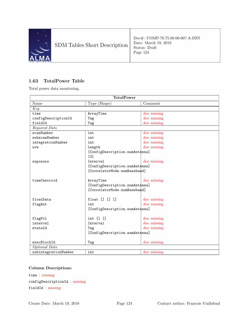
SDM Tables Short Description
Doc#: COMP-70.75.00.00-00?-A-DSNDate: March 19, 2018Status: DraftPage 124
1.63 TotalPower Table
Total power data monitoring.
TotalPowerName Type (Shape) CommentKeytime ArrayTime doc missingconfigDescriptionId Tag doc missingfieldId Tag doc missingRequired DatascanNumber int doc missingsubscanNumber int doc missingintegrationNumber int doc missinguvw Length
[ConfigDescription.numAntenna][3]
doc missing
exposure Interval[ConfigDescription.numAntenna][CorrelatorMode.numBaseband]
doc missing
timeCentroid ArrayTime[ConfigDescription.numAntenna][CorrelatorMode.numBaseband]
doc missing
floatData float [] [] [] doc missingflagAnt int
[ConfigDescription.numAntenna]doc missing
flagPol int [] [] doc missinginterval Interval doc missingstateId Tag
[ConfigDescription.numAntenna]doc missing
execBlockId Tag doc missingOptional DatasubintegrationNumber int doc missing
Column Descriptions:
time : missing
configDescriptionId : missing
fieldId : missing
Create Date: March 19, 2018 Page 124 Contact author: Francois Viallefond

SDM Tables Short Description
Doc#: COMP-70.75.00.00-00?-A-DSNDate: March 19, 2018Status: DraftPage 125
scanNumber : missing
subscanNumber : missing
integrationNumber : missing
uvw : missing
exposure : missing
timeCentroid : missing
floatData : missing
flagAnt : missing
flagPol : missing
interval : missing
stateId : missing
execBlockId : missing
subintegrationNumber : missing
Create Date: March 19, 2018 Page 125 Contact author: Francois Viallefond
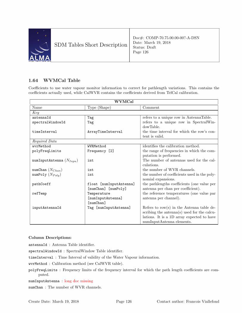
SDM Tables Short Description
Doc#: COMP-70.75.00.00-00?-A-DSNDate: March 19, 2018Status: DraftPage 126
1.64 WVMCal Table
Coefficients to use water vapour monitor information to correct for pathlength variations. This contains thecoefficients actually used, while CalWVR contains the coefficients derived from TelCal calibration.
WVMCalName Type (Shape) CommentKeyantennaId Tag refers to a unique row in AntennaTable.spectralWindowId Tag refers to a unique row in SpectralWin-
dowTable.timeInterval ArrayTimeInterval the time interval for which the row’s con-
tent is valid.Required DatawvrMethod WVRMethod identifies the calibration method.polyFreqLimits Frequency [2] the range of frequencies in which the com-
putation is performed.numInputAntenna (NInpu) int The number of antennas used for the cal-
culations.numChan (NChan) int the number of WVR channels.numPoly (NPoly) int the number of coefficients used in the poly-
nomial expansions.pathCoeff float [numInputAntenna]
[numChan] [numPoly]the pathlengths coefficients (one value perantenna per chan per coefficient).
refTemp Temperature[numInputAntenna][numChan]
the reference temperatures (one value parantenna per channel).
inputAntennaId Tag [numInputAntenna] Refers to row(s) in the Antenna table de-scribing the antenna(s) used for the calcu-lations. It is a 1D array expected to havenumInputAntenna elements.
Column Descriptions:
antennaId : Antenna Table identifier.
spectralWindowId : SpectralWindow Table identifier.
timeInterval : Time Interval of validity of the Water Vapour information.
wvrMethod : Calibration method (see CalWVR table).
polyFreqLimits : Frequency limits of the frequency interval for which the path length coefficients are com-puted.
numInputAntenna : long doc missing
numChan : The number of WVR channels.
Create Date: March 19, 2018 Page 126 Contact author: Francois Viallefond

SDM Tables Short Description
Doc#: COMP-70.75.00.00-00?-A-DSNDate: March 19, 2018Status: DraftPage 127
numPoly : Number of coefficients in polynomial expansion on frequency.
pathCoeff : Pathlength coefficients (see CalWVR table).
refTemp : Reference temperatures (see CalWVR table).
inputAntennaId : long doc missing
Create Date: March 19, 2018 Page 127 Contact author: Francois Viallefond
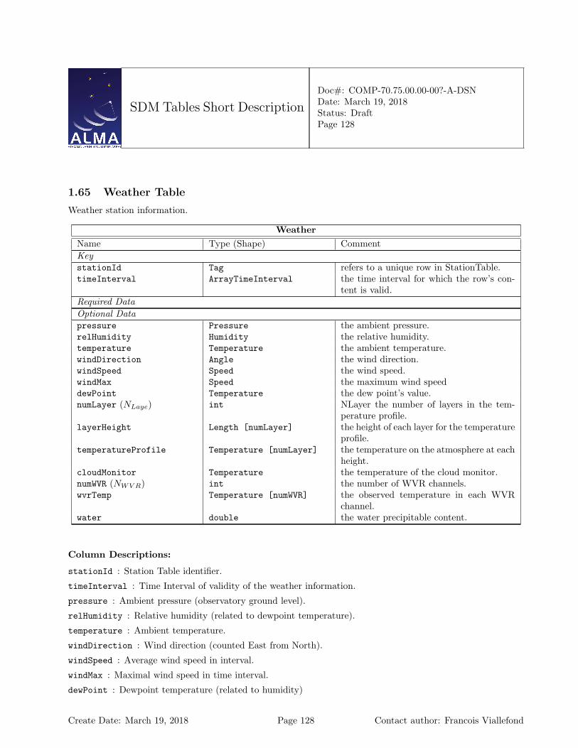
SDM Tables Short Description
Doc#: COMP-70.75.00.00-00?-A-DSNDate: March 19, 2018Status: DraftPage 128
1.65 Weather Table
Weather station information.
WeatherName Type (Shape) CommentKeystationId Tag refers to a unique row in StationTable.timeInterval ArrayTimeInterval the time interval for which the row’s con-
tent is valid.Required DataOptional Datapressure Pressure the ambient pressure.relHumidity Humidity the relative humidity.temperature Temperature the ambient temperature.windDirection Angle the wind direction.windSpeed Speed the wind speed.windMax Speed the maximum wind speeddewPoint Temperature the dew point’s value.numLayer (NLaye) int NLayer the number of layers in the tem-
perature profile.layerHeight Length [numLayer] the height of each layer for the temperature
profile.temperatureProfile Temperature [numLayer] the temperature on the atmosphere at each
height.cloudMonitor Temperature the temperature of the cloud monitor.numWVR (NWV R) int the number of WVR channels.wvrTemp Temperature [numWVR] the observed temperature in each WVR
channel.water double the water precipitable content.
Column Descriptions:
stationId : Station Table identifier.
timeInterval : Time Interval of validity of the weather information.
pressure : Ambient pressure (observatory ground level).
relHumidity : Relative humidity (related to dewpoint temperature).
temperature : Ambient temperature.
windDirection : Wind direction (counted East from North).
windSpeed : Average wind speed in interval.
windMax : Maximal wind speed in time interval.
dewPoint : Dewpoint temperature (related to humidity)
Create Date: March 19, 2018 Page 128 Contact author: Francois Viallefond

SDM Tables Short Description
Doc#: COMP-70.75.00.00-00?-A-DSNDate: March 19, 2018Status: DraftPage 129
numLayer : long doc missing
layerHeight : long doc missing
temperatureProfile : long doc missing
cloudMonitor : long doc missing
numWVR : long doc missing
wvrTemp : long doc missing
water : long doc missing
Create Date: March 19, 2018 Page 129 Contact author: Francois Viallefond

SDM Tables Short Description
Doc#: COMP-70.75.00.00-00?-A-DSNDate: March 19, 2018Status: DraftPage 130
2 List of Enumerations
Create Date: March 19, 2018 Page 130 Contact author: Francois Viallefond
SDM Tables Short Description
Doc#: COMP-70.75.00.00-00?-A-DSNDate: March 19, 2018Status: DraftPage 131
2.1 Versioning information for the enumerations.
– UML description : /home/gondor/bgarwood/alma/almasw/ICD/HLA/Enumerations/idl/ASDM_Enumerations.mdzip
– CVS revision : -1
– CVS branch :
Create Date: March 19, 2018 Page 131 Contact author: Francois Viallefond
SDM Tables Short Description
Doc#: COMP-70.75.00.00-00?-A-DSNDate: March 19, 2018Status: DraftPage 132
2.2 ACAPolarization
version 1 ACA-specific ways to store pre-processed data products
ACA STANDARD : Data product is the standard way (it is a standard observed Stokes parameter)
ACA XX YY SUM : ACA has calculated I by averaging XX and YY
ACA XX 50 : ACA has averaged XX and XX delayed by half a FFT period
ACA YY 50 : ACA has averaged YY and YY delayed by half a FFT period
2.3 AccumMode
version 1 Accumulation modes for the Correlator
FAST : fast dump time. ALMA use case : 1 ms dump time, available only for autocorrelation.
NORMAL : normal dump time. ALMA use case : 16ms dump time, available for both autocorrelation andcross-orrelation.
UNDEFINED : Not defined or not applicable.
2.4 AntennaMake
version 1 The physical types of antenna
AEM 12 : 12m AEM antenna
MITSUBISHI 7 : 7-m Mitsubishi antenna (ACA)
MITSUBISHI 12 A : 12-m Mitsubishi antenna (ACA) (refurbished prototype)
MITSUBISHI 12 B : 12-m Mitsubishi antenna (ACA) (production)
VERTEX 12 ATF : 12-m Vertex antenna prototype
AEM 12 ATF : 12-m AEM antenna prototype
VERTEX 12 : 12-m Vertex antenna
IRAM 15 : 15-m IRAM antenna
UNDEFINED : Not defined or not applicable.
2.5 AntennaMotionPattern
version 1 Motion pattern of antenna , e.g. in a calibration scan.
NONE : No pattern.
CROSS SCAN : Crossed scan (continuous pattern)
SPIRAL : Spiral pattern
CIRCLE : Circular pattern
THREE POINTS : Three points pattern.
FOUR POINTS : Four points pattern.
Create Date: March 19, 2018 Page 132 Contact author: Francois Viallefond
SDM Tables Short Description
Doc#: COMP-70.75.00.00-00?-A-DSNDate: March 19, 2018Status: DraftPage 133
FIVE POINTS : Five points pattern.
TEST : Reserved for development.
UNSPECIFIED : Unspecified pattern.
STAR :
LISSAJOUS :
2.6 AntennaType
version 1 Functional types of antenna
GROUND BASED : Ground-based antenna
SPACE BASED : Antenna in a spacecraft
TRACKING STN : Space-tracking station antenna
2.7 AssociatedCalNature
version 1 These are the associated calibration natures
ASSOCIATED EXECBLOCK : The associated execblock id concatenated to produce the data set
2.8 AssociatedFieldNature
version 1 [ASDM.Field] Nature of the associated field
ON : The associated field is used as ON source data
OFF : The associated field is used as OFF source data
PHASE REFERENCE : The associated field is used as Phase reference data
2.9 AtmPhaseCorrection
version 1 Status of Phase correction
AP UNCORRECTED : Data has no WVR phase correction
AP CORRECTED : Data phases have been corrected using WVR data
2.10 AxisName
version 1 Axis names.
TIM : Time axis.
BAL : Baseline axis.
ANT : Antenna axis.
BAB : Baseband axis.
SPW : Spectral window axis.
Create Date: March 19, 2018 Page 133 Contact author: Francois Viallefond
SDM Tables Short Description
Doc#: COMP-70.75.00.00-00?-A-DSNDate: March 19, 2018Status: DraftPage 134
SIB : Sideband axis.
SUB : Subband axis.
BIN : Bin axis.
APC : Atmosphere phase correction axis.
SPP : Spectral point axis.
POL : Polarization axis (Stokes parameters).
STO : Stokes parameter axis.
HOL : Holography axis.
2.11 BasebandName
version 1 Baseband names
NOBB : Baseband not applicable.
BB 1 : Baseband one
BB 2 : Baseband two
BB 3 : Baseband three
BB 4 : Baseband four
BB 5 : Baseband five (not ALMA)
BB 6 : Baseband six (not ALMA)
BB 7 : Baseband seven (not ALMA)
BB 8 : Baseband eight (not ALMA)
BB ALL : All ALMA basebands (i.e. all available basebands)
A1C1 3BIT :
A2C2 3BIT :
AC 8BIT :
B1D1 3BIT :
B2D2 3BIT :
BD 8BIT :
2.12 BaselineReferenceCode
version 1 defines reference frames to qualify the measure of a baseline.
J2000 : mean equator, equinox J2000.0
B1950 : mean equator, equinox B1950.0
GALACTIC : galactic coordinates.
SUPERGAL : supergalactic coordinates.
Create Date: March 19, 2018 Page 134 Contact author: Francois Viallefond
SDM Tables Short Description
Doc#: COMP-70.75.00.00-00?-A-DSNDate: March 19, 2018Status: DraftPage 135
ECLIPTIC : ecliptic for J2000.0
JMEAN : mean equator.
JTRUE : true equator.
APP : apparent geocentric.
BMEAN : mean equator.
BTRUE : true equator.
JNAT : geocentric natural frame.
MECLIPTIC : ecliptic for mean equator.
TECLIPTIC : ecliptic for true equator.
TOPO : apparent geocentric
MERCURY : from JPL DE table.
VENUS :
MARS :
JUPITER :
SATURN :
NEPTUN :
SUN :
MOON :
HADEC :
AZEL :
AZELGEO :
AZELSW : topocentric Az/El (N =¿ E).
AZELNE : idem AZEL.
ITRF : ITRF earth frame.
2.13 BinaryDataFlags
version 1 This enumeration declares an ordered list of flagging conditions used to build the flag part in theBDF content. Each enumerator is associated to one bit in a bitset. A bit set to one (resp. zero) meansthat the corresponding flagging condition is set (resp. unset). The current convention limits the length of theenumeration to 32; the position (0-based) of the enumerator in the enumeration defines the bit position. Anybit whose position is greater or equal to the length of the enumeration and less than 32 should be ignored bythe software since it does not correspond to any flagging condition.
INTEGRATION FULLY BLANKED : All dumps within an integration duration are blanked. When this flag is raisedthe effect is to have the bin part actualDurations containing zeros? In other words it means ’all dumpsaffected’. Bit position == 0
WVR APC : Coefficients not received.Apply to all BAL involving the antenna. Bit position == 1
Create Date: March 19, 2018 Page 135 Contact author: Francois Viallefond
SDM Tables Short Description
Doc#: COMP-70.75.00.00-00?-A-DSNDate: March 19, 2018Status: DraftPage 136
CORRELATOR MISSING STATUS : Correlator status was not retrieved for the period. So yielded data are notreliable. Apply to all BBs handled by the correlator. Bit position == 2
MISSING ANTENNA EVENT : Antenna delay event was not retrieved for the period. So yielded data are notreliable. BALs including the antenna. Bit position == 3
DELTA SIGMA OVERFLOW : In data transmission between the MTI cards, there are one or more channels whoseabsolute value differences between adjacent channel values are bigger than the maximum number. Bitposition == 4
DELAY CORRECTION NOT APPLIED : no residual delay correction was applied. It implies that either base-bandoffset delays from TMCDB were not available or that delay events from the delay server were not receivedon time to compute and apply a phase rotation to base-lines in the array. == 5
SYNCRONIZATION ERROR : cdp node(s) not properly synchronized to the array timing signal (48ms.) All dataproduced by that node(s) are suspicious.Lags and spectral processing goes as normal, it is just the flagpresence in the bdf what indicates that something is suspicious. Bit position == 6
FFT OVERFLOW : Overflowed POL and derived outputs from it. Dumps between the timestamp marked as FFToverflowed and the time back to 96msec before. Bit position == 7
TFB SCALING FACTOR NOT RETRIEVED : CCC cannot retrieve scaling factors during calibration for specific an-tennas the calibration would still end successfully but the cdp will record the faulty scaling factors andadd a flag to all involved base-lines. Bit position == 8
ZERO LAG NOT RECEIVED : CDP node handling only cross antenna intersections did not receive lag zero informa-tion from node(s) handling auto intersections for involved antennas in that cross intersection. Bit position== 9
SIGMA OVERFLOW : Auto-correlation sigma levels makes impossible any 2 bits quantizationcorrection on lags data. One sigma value out of range affects that antenna itselfand all base-lines containing that antenna. Is it possible to merge this flags withDELTASIGMAOV ERFLOW?Thedifferenceseemstobethegranularity.IfitisPOLACACORRwouldhavetorepeattheflagforeveryPOLbecauseperbasebandthereareseveralPOL.Bitposition==10:Theoutputspectraaremadefrominvalidinputsignals, e.g., brokenopticalframes,missingsynchronizationornoinputsignalpower.Bitposition==11
UNUSABLE CAI OUTPUTQC FAILED : Quantization correction not applied due to unsuitable lag zero value. BL-CORR note:every possible signal level should be actually accepted (too small or too big), the presence of this bit signalsmore a software problem than an antenna signal problem. Bit position == 12
NOISY TDM CHANNELS : First TDM channels are normally noisy and they have a large amplitude. If that excess ofamplitude in those channels would be the sole reason for keeping the integration storage at 32 bits integers thenthe software clips those channels and flags the data. Thus preventing large storage for otherwise 16 bits friendlydynamic range. Bit position == 13
SPECTRAL NORMALIZATION FAILED : Auto-correlation and zero-lags figures are required to normalize cross-correlationspectra as prescribed in Scott’s ’Specifications and Clarifications of ALMA Correlator Details’. If those figuresare not available on time during on-line processing then crosscorrelations are not normalized and the integrationflagged. Bit position == 14
DROPPED PACKETS : T.B.D. Bit position == 15
DETECTOR SATURATED : T.B.D. Bit position == 16
NO DATA FROM DIGITAL POWER METER : The current data from digital power meter are available for the calculation ofthe 3-bit linearity correction. An old correction factor is applied. Bit position == 17
Create Date: March 19, 2018 Page 136 Contact author: Francois Viallefond
SDM Tables Short Description
Doc#: COMP-70.75.00.00-00?-A-DSNDate: March 19, 2018Status: DraftPage 137
RESERVED 18 : Not assigned.
RESERVED 19 : Not assigned.
RESERVED 20 : Not assigned.
RESERVED 21 : Not assigned.
RESERVED 22 : Not assigned.
RESERVED 23 : Not assigned.
RESERVED 24 : Not assigned.
RESERVED 25 : Not assigned.
RESERVED 26 : Not assigned.
RESERVED 27 : Not assigned.
RESERVED 28 : Not assigned.
RESERVED 29 : Not assigned.
RESERVED 30 : Not assigned.
ALL PURPOSE ERROR : This bit designates data flagged in the correlator but does not provide information as to thereason for the flag. Readers are expected not to process the data when this bit is set. Bit position == 31.
2.14 CalCurveType
version 1 [CalDM.CalCurve] type pf calibration curve
AMPLITUDE : Calibration curve is Amplitude
PHASE : Calibration curve is phase
UNDEFINED : Not applicable.
2.15 CalDataOrigin
version 1
TOTAL POWER
WVR
CHANNEL AVERAGE AUTO
CHANNEL AVERAGE CROSS
FULL RESOLUTION AUTO
FULL RESOLUTION CROSS
OPTICAL POINTING
HOLOGRAPHY
NONE
Create Date: March 19, 2018 Page 137 Contact author: Francois Viallefond

SDM Tables Short Description
Doc#: COMP-70.75.00.00-00?-A-DSNDate: March 19, 2018Status: DraftPage 138
2.16 CalType
version 1 [CalDM.CalData] Used to point to a given CalResult table
CAL AMPLI :
CAL ATMOSPHERE :
CAL BANDPASS :
CAL CURVE :
CAL DELAY :
CAL FLUX :
CAL FOCUS :
CAL FOCUS MODEL :
CAL GAIN :
CAL HOLOGRAPHY :
CAL PHASE :
CAL POINTING :
CAL POINTING MODEL :
CAL POSITION :
CAL PRIMARY BEAM :
CAL SEEING :
CAL WVR :
CAL APPPHASE : Calibration for phasing of ALMA. Applicable at ALMA.
2.17 CalibrationDevice
version 1 Devices that may be inserted in the optical path in front of the receiver.
AMBIENT LOAD : An absorbing load at the ambient temperature.
COLD LOAD : A cooled absorbing load.
HOT LOAD : A heated absorbing load.
NOISE TUBE LOAD : A noise tube.
QUARTER WAVE PLATE : A transparent plate that introduces a 90-degree phase difference between othogonalpolarizations.
SOLAR FILTER : An optical attenuator (to protect receiver from solar heat).
NONE : No device, the receiver looks at the sky (through the telescope).
Create Date: March 19, 2018 Page 138 Contact author: Francois Viallefond
SDM Tables Short Description
Doc#: COMP-70.75.00.00-00?-A-DSNDate: March 19, 2018Status: DraftPage 139
2.18 CalibrationFunction
version 1 Function of a scan in a calibration set. Useful only in real time.
FIRST : the scan is the first in a calibration set.
LAST : the scan is the last in a calibration set.
UNSPECIFIED : the function is not specified.
2.19 CalibrationMode
version 1 Modes of calibration
HOLOGRAPHY : Holography receiver
INTERFEROMETRY : interferometry
OPTICAL : Optical telescope
RADIOMETRY : total power
WVR : water vapour radiometry receiver
2.20 CalibrationSet
version 1 Defines sets of calibration scans to be reduced together for a result.
NONE : Scan is not part of a calibration set.
AMPLI CURVE : Amplitude calibration scan (calibration curve to be derived).
ANTENNA POSITIONS : Antenna positions measurement.
PHASE CURVE : Phase calibration scan (calibration curve to be derived).
POINTING MODEL : Pointing calibration scan (pointing model to be derived).
ACCUMULATE : Accumulate a scan in a calibration set.
TEST : Reserved for development.
UNSPECIFIED : Unspecified calibration intent.
2.21 CorrelationBit
version 1 [APDM] Number of bits used for correlation
BITS 2x2 : two bit correlation
BITS 3x3 : three bit correlation
BITS 4x4 : four bit correlation
Create Date: March 19, 2018 Page 139 Contact author: Francois Viallefond
SDM Tables Short Description
Doc#: COMP-70.75.00.00-00?-A-DSNDate: March 19, 2018Status: DraftPage 140
2.22 CorrelationMode
version 1 [ASDM.Binary] Actual data products in binary data
CROSS ONLY : Cross-correlations only [not for ALMA]
AUTO ONLY : Auto-correlations only
CROSS AND AUTO : Auto-correlations and Cross-correlations
2.23 CorrelatorCalibration
version 1 Internal correlator calibrations performed duting this subscan
NONE : No internal correlator calibration
CORRELATOR CALIBRATION : Internal correlator calibration.
REAL OBSERVATION : A ’real’ observation.
2.24 CorrelatorName
version 1
ALMA ACA
ALMA BASELINE
ALMA BASELINE ATF
ALMA BASELINE PROTO OSF
HERSCHEL
IRAM PDB
IRAM 30M VESPA
IRAM WILMA
NRAO VLA
NRAO WIDAR
2.25 CorrelatorType
version 1 defines the type of a correlator.
FX : identifies a digital correlator of type FX.
XF : identifies a digital correlator of type XF.
FXF : identifies a correlator of type FXF.
Create Date: March 19, 2018 Page 140 Contact author: Francois Viallefond

SDM Tables Short Description
Doc#: COMP-70.75.00.00-00?-A-DSNDate: March 19, 2018Status: DraftPage 141
2.26 DataContent
version 1 [ASDM.Binaries] Contents of binary data attachment
CROSS DATA : Cross-correlation data
AUTO DATA : Auto-correlation data
ZERO LAGS : Zero-lag data
ACTUAL TIMES : :Actual times (mid points of integrations)
ACTUAL DURATIONS : Actual duration of integrations
WEIGHTS : Weights
FLAGS : Baseband based flags
2.27 DataScale
version 1 Units of the cross and auto data in the BDF.
K : Visibilities in Antenna temperature scale (in Kelvin).
JY : Visibilities in Flux Density scale (Jansky).
CORRELATION : Correlated Power: WIDAR raw output, normalised by DataValid count.
CORRELATION COEFFICIENT : Correlation Coe4;cient (Correlated Power scaled by autocorrelations).
2.28 DetectorBandType
version 1 [ASDM.SquareLawDetector] Types of detectors
BASEBAND : Detector in Baseband Processor
DOWN CONVERTER : Detector in Down - Converter
HOLOGRAPHY RECEIVER : Detector in Holography Receiver
SUBBAND : Detector in subband (tunable digital filter).
2.29 DifferenceType
version 1 An enumeration to qualify the values in the columns polarOffsetsType and timeType in the tableDelayModelVariableParameters.
PREDICTED :
PRELIMINARY :
RAPID :
FINAL :
Create Date: March 19, 2018 Page 141 Contact author: Francois Viallefond
SDM Tables Short Description
Doc#: COMP-70.75.00.00-00?-A-DSNDate: March 19, 2018Status: DraftPage 142
2.30 DirectionReferenceCode
version 1 defines reference frames to qualify the measure of a direction.
J2000 : mean equator and equinox at J2000.0
JMEAN : mean equator and equinox at frame epoch.
JTRUE : true equator and equinox at frame epoch.
APP : apparent geocentric position.
B1950 : mean epoch and ecliptic at B1950.0.
B1950 VLA :
BMEAN : mean equator and equinox at frame epoch.
BTRUE : true equator and equinox at frame epoch.
GALACTIC : galactic coordinates.
HADEC : topocentric HA and declination.
AZELSW : topocentric Azimuth and Elevation (N through E).
AZELSWGEO :
AZELNE : idem AZEL
AZELNEGEO :
JNAT : geocentric natural frame.
ECLIPTIC : ecliptic for J2000.0 equator, equinox.
MECLIPTIC : ecliptic for mean equator of date.
TECLIPTIC : ecliptic for true equatorof date.
SUPERGAL : supergalactic coordinates.
ITRF : coordinates wrt ITRF earth frame.
TOPO : apparent topocentric position.
ICRS :
MERCURY : from JPL DE table.
VENUS :
MARS :
JUPITER :
SATURN :
URANUS :
NEPTUNE :
PLUTO :
SUN :
MOON :
Create Date: March 19, 2018 Page 142 Contact author: Francois Viallefond
SDM Tables Short Description
Doc#: COMP-70.75.00.00-00?-A-DSNDate: March 19, 2018Status: DraftPage 143
2.31 DopplerReferenceCode
version 1 defines reference frames to qualify the measure of a radial velocity expressed as doppler shift.
RADIO : radio definition : 1− FZ : redshift : −1 + 1/FRATIO : frequency ratio : FBETA : relativistic : (1− F 2)/(1 + F 2)GAMMA : (1 + F 2)/(2 ∗ F )OPTICAL : ZZRELATIVISTIC : idem BETA
2.32 DopplerTrackingMode
version 1 Enumerations of different modes used in doppler tracking.
NONE : No Doppler tracking.CONTINUOUS : Continuous (every integration) Doppler tracking.SCAN BASED : Doppler tracking only at scan boundaries. This means we update the observing frequency to the
correct value, but only at scan boundaries.SB BASED : Doppler tracking only at the beginning of the Scheduling Block. We set the frequency at the
beginning of the observation but leave it fixed thereafter. For the EVLA this is referred to as ’Dopplersetting’.
2.33 FieldCode
version 1 [ASDM.Field] code for Field
NONE :
2.34 FilterMode
version 1 [APDM.Correlator] Modes of correlator input filtering
FILTER NA : Not Applicable (2 antenna prototype). The Tunable Filter Banks are not implementedFILTER TDM : Time Division Mode. In this mode the Tunable Filter banks are bypassedFILTER TFB : The Tunable Filter Bank is implemented and usedUNDEFINED : Not defined or not applicable.
2.35 FluxCalibrationMethod
version 1 [CalDM.CalFlux] Methods for flux calibration
ABSOLUTE : Absolute flux calibration (based on standard antenna)RELATIVE : Relative flux calibration (based on a primary calibrator)EFFICIENCY : Flux calibrator based on tabulated antenna efficiciency
Create Date: March 19, 2018 Page 143 Contact author: Francois Viallefond
SDM Tables Short Description
Doc#: COMP-70.75.00.00-00?-A-DSNDate: March 19, 2018Status: DraftPage 144
2.36 FocusMethod
version 1 [CalDM.CalFocus] Method of focus measurement
THREE POINT : Three-point measurement
FIVE POINT : Five-point measurement
HOLOGRAPHY :
2.37 FrequencyReferenceCode
version 1 defines reference frames to qualify the measure of a frequency.
LABREST : spectral line rest frequency.
LSRD : dynamic local standard of rest.
LSRK : kinematic local standard rest.
BARY : barycentric frequency.
REST : spectral line frequency
GEO : geocentric frequency.
GALACTO : galactocentric frequency.
TOPO : topocentric frequency.
2.38 HolographyChannelType
version 1 [ASDM.Holography] Type sof holography receiver output channels
Q2 : Quadrature channel auto-product
QR : Quadrature channel times Reference channel cross-product
QS : Quadrature channel times Signal channel cross-product
R2 : Reference channel auto-product
RS : Reference channel times Signal channel cross-product
S2 : Signal channel auto-product
2.39 InvalidatingCondition
version 1 [CalDM.CalReduction] Contitions invalidating result
ANTENNA DISCONNECT : Antenna was disconnected
ANTENNA MOVE : Antenna was moved
ANTENNA POWER DOWN : Antenna was powered down
RECEIVER EXCHANGE : Receiver was exchanged
RECEIVER POWER DOWN : Receiver was powered down
Create Date: March 19, 2018 Page 144 Contact author: Francois Viallefond

SDM Tables Short Description
Doc#: COMP-70.75.00.00-00?-A-DSNDate: March 19, 2018Status: DraftPage 145
2.40 NetSideband
version 1 [ASDM.SpectralWindow] Equivalent side band of spectrum frequency axis
NOSB : No side band (no frequency conversion)
LSB : Lower side band
USB : Upper side band
DSB : Double side band
2.41 PointingMethod
version 1 [CalDM.CalPointing] Method of pointing measurement
THREE POINT : Three-point scan
FOUR POINT : Four-point scan
FIVE POINT : Five-point scan
CROSS : Cross scan
CIRCLE : Circular scan
HOLOGRAPHY :
2.42 PointingModelMode
version 1 [CalDM.PointingModel] Mode of Pointing Model
RADIO : Radio pointing model
OPTICAL : Optical Pointing Model
2.43 PolarizationType
version 1 The polarizations a single receptor can detect
R : Right-handed Circular
L : Left-handed Circular
X : X linear
Y : Y linear
BOTH : The receptor responds to both polarizations.
2.44 PositionMethod
version 1 [CalDM.CalPositions] Method used for measuring antenna positions
DELAY FITTING : Delays are measured for each source; the delays are used for fitting antenna position errors.
PHASE FITTING : Phases are measured for each source; these phases are used to fit antenna position errors.
Create Date: March 19, 2018 Page 145 Contact author: Francois Viallefond
SDM Tables Short Description
Doc#: COMP-70.75.00.00-00?-A-DSNDate: March 19, 2018Status: DraftPage 146
2.45 PositionReferenceCode
version 1 defines reference frames to qualify the measure of a position.
ITRF : International Terrestrial Reference Frame.
WGS84 : World Geodetic System.
SITE : Site reference coordinate system (ALMA-80.05.00.00-009-B-SPE).
STATION : Antenna station reference coordinate system (ALMA-80.05.00.00-009-SPE).
YOKE : Antenna yoke reference coordinate system (ALMA-980.05.00.00-009-B-SPE)
REFLECTOR : Antenna reflector reference coordinate system (ALMA-80.05.00.00-009-B-SPE).
2.46 PrimaryBeamDescription
version 1 Nature of the quantity tabulated to describe the primary beam.
COMPLEX FIELD PATTERN : Electric Field Pattern image at infinite distance from antenna.
APERTURE FIELD DISTRIBUTION : Electric Field aperture distribution.
2.47 PrimitiveDataType
version 1 [ASDM.Binaries] Primitive data types for binary MIME attachments
INT16 TYPE : 2 bytes signed integer (short).
INT32 TYPE : 4 bytes signed integer (int).
INT64 TYPE : 8 bytes signed integer (long long).
FLOAT32 TYPE : 4 bytes float (float).
FLOAT64 TYPE : 8 bytes float (double).
2.48 ProcessorSubType
version 1 [ASDM.Processor] The tables used to contain device configuration data
ALMA CORRELATOR MODE : ALMA correlator.
SQUARE LAW DETECTOR : Square law detector.
HOLOGRAPHY : Holography.
ALMA RADIOMETER : ALMA radiometer.
2.49 ProcessorType
version 1 [ASDM.Processor] Types of processors
CORRELATOR : A digital correlator
RADIOMETER : A radiometer
SPECTROMETER : An (analogue) multi-channel spectrometer
Create Date: March 19, 2018 Page 146 Contact author: Francois Viallefond
SDM Tables Short Description
Doc#: COMP-70.75.00.00-00?-A-DSNDate: March 19, 2018Status: DraftPage 147
2.50 RadialVelocityReferenceCode
version 1
LSRD
LSRK
GALACTO
BARY
GEO
TOPO
2.51 ReceiverBand
version 1 [ASDM.Receiver] Receiver band names
ALMA RB 01 : ALMA Receiver band 01
ALMA RB 02 : ALMA Receiver band 02
ALMA RB 03 : ALMA Receiver band 03
ALMA RB 04 : ALMA Receiver band 04
ALMA RB 05 : ALMA Receiver band 05
ALMA RB 06 : ALMA Receiver band 06
ALMA RB 07 : ALMA Receiver band 07
ALMA RB 08 : ALMA Receiver band 08
ALMA RB 09 : ALMA Receiver band 09
ALMA RB 10 : ALMA Receiver band 10
ALMA RB ALL : all ALMA receiver bands.
ALMA HOLOGRAPHY RECEIVER : Alma transmitter Holography receiver.
BURE 01 : Plateau de Bure receiver band 1.
BURE 02 : Plateau de Bure receiver band 2.
BURE 03 : Plateau de Bure receiver band 3.
BURE 04 : Plateau de Bure receiver band 4
EVLA 4 :
EVLA P :
EVLA L :
EVLA C :
EVLA S :
EVLA X :
EVLA Ku :
Create Date: March 19, 2018 Page 147 Contact author: Francois Viallefond
SDM Tables Short Description
Doc#: COMP-70.75.00.00-00?-A-DSNDate: March 19, 2018Status: DraftPage 148
EVLA K :
EVLA Ka :
EVLA Q :
UNSPECIFIED : receiver band of unspecified origin.
2.52 ReceiverSideband
version 1 [ASDM.SpectralWindow] The type of receiver output a spectral window is fed with
NOSB : direct output signal (no frequency conversion).
DSB : double side band ouput.
SSB : single side band receiver.
TSB : receiver with dual output.
2.53 SBType
version 1 [ASDM.SBSummary] Types of Scheduling Block
OBSERVATORY : Observatory mode scheduling block
OBSERVER : Observer mode scheduling block
EXPERT : Expert mode scheduling block
2.54 ScanIntent
version 1 [ASDM.Scan] Scan intents
CALIBRATE AMPLI : Amplitude calibration scan
CALIBRATE ATMOSPHERE : Atmosphere calibration scan
CALIBRATE BANDPASS : Bandpass calibration scan
CALIBRATE DELAY : Delay calibration scan
CALIBRATE FLUX : flux measurement scan.
CALIBRATE FOCUS : Focus calibration scan. Z coordinate to be derived
CALIBRATE FOCUS X : Focus calibration scan; X focus coordinate to be derived
CALIBRATE FOCUS Y : Focus calibration scan; Y focus coordinate to be derived
CALIBRATE PHASE : Phase calibration scan
CALIBRATE POINTING : Pointing calibration scan
CALIBRATE POLARIZATION : Polarization calibration scan
CALIBRATE SIDEBAND RATIO : measure relative gains of sidebands.
CALIBRATE WVR : Data from the water vapor radiometers (and correlation data) are used to derive their cali-bration parameters.
Create Date: March 19, 2018 Page 148 Contact author: Francois Viallefond

SDM Tables Short Description
Doc#: COMP-70.75.00.00-00?-A-DSNDate: March 19, 2018Status: DraftPage 149
DO SKYDIP : Skydip calibration scan
MAP ANTENNA SURFACE : Holography calibration scan
MAP PRIMARY BEAM : Data on a celestial calibration source are used to derive a map of the primary beam.
OBSERVE TARGET : Target source scan
CALIBRATE POL LEAKAGE :
CALIBRATE POL ANGLE :
TEST : used for development.
UNSPECIFIED : Unspecified scan intent
CALIBRATE ANTENNA POSITION : Requested by EVLA.
CALIBRATE ANTENNA PHASE : Requested by EVLA.
MEASURE RFI : Requested by EVLA.
CALIBRATE ANTENNA POINTING MODEL : Requested by EVLA.
SYSTEM CONFIGURATION : Requested by EVLA.
CALIBRATE APPPHASE ACTIVE : Calculate and apply phasing solutions. Applicable at ALMA.
CALIBRATE APPPHASE PASSIVE : Apply previously obtained phasing solutions. Applicable at ALMA.
OBSERVE CHECK SOURCE :
CALIBRATE DIFFGAIN : Enable a gain differential target type
2.55 SchedulerMode
version 1 [ASDM.SBSummary] Scheduler operation mode
DYNAMIC : Dynamic scheduling
INTERACTIVE : Interactive scheduling
MANUAL : Manual scheduling
QUEUED : Queued scheduling
2.56 SidebandProcessingMode
version 1 [ASDM.SpectralWindow] Real-time processing to derive sideband data
NONE : No processing
PHASE SWITCH SEPARATION : Side band separation using 90-degree phase switching
FREQUENCY OFFSET SEPARATION : Side band separation using offsets of first ans second oscillators
PHASE SWITCH REJECTION : Side band rejection 90-degree phase switching
FREQUENCY OFFSET REJECTION : Side band rejection using offsets of first and second oscillators
Create Date: March 19, 2018 Page 149 Contact author: Francois Viallefond
SDM Tables Short Description
Doc#: COMP-70.75.00.00-00?-A-DSNDate: March 19, 2018Status: DraftPage 150
2.57 SourceModel
version 1 [CalDM.CalFlux] Source Model
GAUSSIAN : Gaussian source
POINT : Point Source
DISK : Uniform Disk
2.58 SpectralResolutionType
version 1 [ASDM.SpectralWindow] The types of spectral resolutions for spectral windows.
CHANNEL AVERAGE :
BASEBAND WIDE :
FULL RESOLUTION :
2.59 StationType
version 1 [ASDM.Station] Type of antenna station
ANTENNA PAD : Astronomical Antenna station
MAINTENANCE PAD : Maintenance antenna station
WEATHER STATION : Weather station
2.60 StokesParameter
version 1 Stokes parameters (CASA definition)
I :
Q :
U :
V :
RR :
RL :
LR :
LL :
XX : Linear correlation product
XY :
YX :
YY :
RX : Mixed correlation product
RY : Mixed correlation product
Create Date: March 19, 2018 Page 150 Contact author: Francois Viallefond
SDM Tables Short Description
Doc#: COMP-70.75.00.00-00?-A-DSNDate: March 19, 2018Status: DraftPage 151
LX : Mixed LX product
LY : Mixed LY correlation product
XR : Mixed XR correlation product
XL : Mixed XL correlation product
YR : Mixed YR correlation product
YL : Mixel YL correlation product
PP :
PQ :
QP :
QQ :
RCIRCULAR :
LCIRCULAR :
LINEAR : single dish polarization type
PTOTAL : Polarized intensity ((Q2 + U2 + V 2)(1/2)) : LinearlyPolarizedintensity((Q2 + U2)(1/2))
PLINEARPFTOTAL : Polarization Fraction (Ptotal/I)
PFLINEAR : Linear Polarization Fraction (Plinear/I)
PANGLE : Linear Polarization Angle (0.5 arctan(U/Q)) (in radians)
2.61 SubscanIntent
version 1 [ASDM.Subscan] Precise the intent for a subscan
ON SOURCE : on-source measurement
OFF SOURCE : off-source measurement
MIXED : Pointing measurement, some antennas are on -ource, some off-source
REFERENCE : reference measurement (used for boresight in holography).
SCANNING : antennas are scanning.
HOT : hot load measurement.
AMBIENT : ambient load measurement.
SIGNAL : Signal sideband measurement.
IMAGE : Image sideband measurement.
TEST : reserved for development.
UNSPECIFIED : Unspecified
Create Date: March 19, 2018 Page 151 Contact author: Francois Viallefond
SDM Tables Short Description
Doc#: COMP-70.75.00.00-00?-A-DSNDate: March 19, 2018Status: DraftPage 152
2.62 SwitchingMode
version 1 Switching modes: there are two categories of switching modes, those at high rate (chopper wheel,nutator and frequency switch) which involve the BIN axis and those at low rate (frequency, position, load andphase switching) unrelated to the bin axis. Note that in case of frequency switching mode it is the contextwhich tells in which of these two categories it is used.
NO SWITCHING : No switching
LOAD SWITCHING : Receiver beam is switched between sky and load
POSITION SWITCHING : Antenna (main reflector) pointing direction is switched
PHASE SWITCHING : 90 degrees phase switching (switching mode used for sideband separation or rejection withDSB receivers)
FREQUENCY SWITCHING : LO frequency is switched (definition context sensitive: fast if cycle shrorter than theintegration duration, slow if e.g. step one step per subscan)
NUTATOR SWITCHING : Switching between different directions by nutating the sub-reflector
CHOPPER WHEEL : Switching using a chopper wheel
2.63 SynthProf
version 1
NOSYNTH
ACACORR
ACA CDP
2.64 SyscalMethod
version 1 [CalDM.CalAtmosphere] Atmosphere calibration methods
TEMPERATURE SCALE : Use single direction data to compute ta* scale
SKYDIP : Use a skydip (observing the sky at various elevations) to get atmospheric opacity
SIDEBAND RATIO : Measure the sideband gain ratio.
2.65 TimeSampling
version 1 Time granularity for data
SUBINTEGRATION : Part of an integration
INTEGRATION : Part of a subscan. An integration may be composed of several sub-integrations.
2.66 TimeScale
version 1 Time standards.
UTC : Coordinated Universal Time.
TAI : International Atomic Time.
Create Date: March 19, 2018 Page 152 Contact author: Francois Viallefond
SDM Tables Short Description
Doc#: COMP-70.75.00.00-00?-A-DSNDate: March 19, 2018Status: DraftPage 153
2.67 WVRMethod
version 1 [CalDM.CalWVR] Methods for WVR Data processing in TelCal
ATM MODEL : WVR data reduction uses ATM model
EMPIRICAL : WVR data reduction optimized using actual phase data
2.68 WeightType
version 1
K
JY
COUNT WEIGHT
2.69 WindowFunction
version 1 [APDM; ASDM.ALmaCorrelatorMode] Windowing functions for spectral data apodization
UNIFORM : No windowing
HANNING : Raised cosine: 0.5 ∗ (1− cos(x)) where x = 2 ∗ π ∗ i/(N − 1)
HAMMING : The classic Hamming window is WM (x) = 0.54 − 0.46 ∗ cos(x). This is generalized to WM (x) =β − (1 − β) ∗ cos(x) where β can take any value in the range [0, 1]. β = 0.5 corresponds to the Hanningwindow.
BARTLETT : The Bartlett (triangular) window is 1− |x/π|, where x = 2 ∗ π ∗ i/(N − 1).
BLACKMANN : The window function is WB(x) = (0.5−β)−0.5∗cos(xj)+β∗cos(2xj), where xj = 2∗π∗j/(N−1).The classic Blackman window is given by β = 0.08.
BLACKMANN HARRIS : The BLACKMANNHARRISwindowis1.0 - 1.36109*cos(x) + 0.39381 ∗ cos(2 ∗ x) −0.032557 ∗ cos(3 ∗ x), where x = 2 ∗ π ∗ i/(N − 1).
WELCH : The Welch window (parabolic) is 1− (2 ∗ i/N)2.
Create Date: March 19, 2018 Page 153 Contact author: Francois Viallefond