sdc pds rcvd 02-05-15 tm5588 review ... california. this investigation included a review of...
TRANSCRIPT

SDC PDS RCVD 02-05-15 TM5588

ENGINEERS + GEOLOGISTS + ENVIRONMENTAL SCIENTISTS
Offices Strategically Positioned Throughout Southern California RIVERSIDE COUNTY OFFICE 40880 County Center Drive, Suite R, Temecula, CA 92591 T: 951.600.9271 F: 951.719.1499 For more information visit us online at www.petra-inc.com
September 4, 2013
(Reissued January 19, 2015) J.N. 13-357
Mr. Ray Dorame SAM-SWEETWATER, LLC 20201 SW Birch Street, Suite 100 Newport Beach, CA 92660
Subject: Revised Feasibility/Due-diligence Geotechnical Investigation, Proposed Residential
Development, Sweetwater Village Project, APN 505-231-36 (Formerly APN 760-128-54-00), 2657 Sweetwater Springs Boulevard, Spring Valley, San Diego County, California
Dear Mr. Dorame: In accordance with your request and authorization, Petra Geosciences, Inc. (Petra) is pleased to submit
herewith our revised feasibility/due-diligence geotechnical investigation report for the proposed
residential development (Sweetwater Village Project), located at 2657 Sweetwater Springs Boulevard in
Spring Valley, San Diego County, California. This work was performed in general accordance with the
scope of work outlined in our Proposal No. 13-357-P dated June 24, 2013. This revised report presents
the results of our field exploration, laboratory testing, and our engineering judgment, opinions,
conclusions and recommendations pertaining to preliminary geotechnical design aspects for the proposed
residential development.

SAM-SWEETWATER, LLC September 4, 2013 (Reissued January 19, 2015) 2657 Sweetwater Springs Boulevard/San Diego County J.N. 13-357 Page 2
It has been a pleasure to be of service to you on this project. Should you have questions regarding the
contents of this report or should you require additional information, please contact this office.
Respectfully submitted,
PETRA GEOSCIENCES, INC. Todd Greer, CEG Grayson R. Walker, GE Senior Project Geologist Vice President CEG 2377 TG/GRW/nbc Distribution: (4) Addressee

SAM-SWEETWATER, LLC September 4, 2013 (Reissued January 19, 2015) 2657 Sweetwater Springs Boulevard/San Diego County J.N. 13-357 Page ii
TABLE OF CONTENTS Page INTRODUCTION .......................................................................................................................... 1
Purpose and Scope of Services ............................................................................................... 1 Location and Site Description ................................................................................................. 2 Proposed Construction ............................................................................................................ 2 Literature Review .................................................................................................................... 3 Subsurface Exploration ........................................................................................................... 3 Laboratory Testing .................................................................................................................. 3
FINDINGS ...................................................................................................................................... 4 Regional Geologic Setting ...................................................................................................... 4 Local Geology and Subsurface Soil Conditions ..................................................................... 4 Groundwater ........................................................................................................................... 4 Faulting ................................................................................................................................... 5
CONCLUSIONS AND RECOMMENDATIONS ......................................................................... 5 General .................................................................................................................................... 5
Geologic Considerations ............................................................................................................. 5 Groundwater ........................................................................................................................... 5 Fault Rupture .......................................................................................................................... 6 Seismic Shaking ...................................................................................................................... 6 Secondary Effects of Seismic Activity ................................................................................... 6 Landslides and Slope Instability ............................................................................................. 7 Surface Flooding ..................................................................................................................... 7 Expansive Soils ....................................................................................................................... 7 Areal Subsidence .................................................................................................................... 7 Liquefaction and Seismically-Induced Settlement ................................................................. 8
Earthwork .................................................................................................................................... 8 General Earthwork Recommendations ................................................................................... 8 Clearing and Grubbing ............................................................................................................ 9 Geotechnical Observations and Testing .................................................................................. 9 Ground Preparation – Foundation Areas ................................................................................ 9 Ground Preparation – Cut Areas ........................................................................................... 10 Ground Preparation – Roadways and Sheet-Graded Areas .................................................. 10 Fill Placement and Testing .................................................................................................... 11 Geotechnical Observations ................................................................................................... 11 Shrinkage and Subsidence .................................................................................................... 11
Foundation Systems .................................................................................................................. 12 General .................................................................................................................................. 12 Allowable Soil Bearing Capacities ....................................................................................... 12 Footing Settlement ................................................................................................................ 12 Lateral Resistance ................................................................................................................. 12

SAM-SWEETWATER, LLC September 4, 2013 (Reissued January 19, 2015) 2657 Sweetwater Springs Boulevard/San Diego County J.N. 13-357 Page iii
Conventional Slab-on-Ground Foundations ......................................................................... 13 Post-Tensioned Slab-on-Ground Foundations ...................................................................... 15
General Corrosivity Screening .................................................................................................. 18 Concrete in Contact with Site Soils ...................................................................................... 18 Metals Encased in Concrete .................................................................................................. 19 Metallic Elements in Contact with Site Soils ....................................................................... 20
Post-Grading Recommendations .............................................................................................. 20 Site Drainage ......................................................................................................................... 20 Utility Trenches .................................................................................................................... 21
PLAN REVIEW AND CONSTRUCTION SERVICES .............................................................. 21 LIMITATIONS ............................................................................................................................. 22 Attachments References Figure 1 – Site Location Map Figure 2 – Boring Location Map Appendices Appendix A – Boring Logs Appendix B – Laboratory Test Criteria/Laboratory Test Data

FEASIBILITY/DUE-DILIGENCE GEOTECHNICAL INVESTIGATION PROPOSED RESIDENTIAL DEVELOPMENT
SWEETWATER VILLAGE PROJECT, APN 505-231-36 (Formerly APN 760-128-54-00), 2657 SWEETWATER SPRINGS BOULEVARD
SPRING VALLEY, SAN DIEGO COUNTY, CALIFORNIA
INTRODUCTION This revised report presents the results of Petra Geosciences, Inc.'s (Petra) feasibility/due-diligence
geotechnical investigation for the proposed residential development of the Sweetwater Village Project
APN 505-231-36 (Formerly APN 760-128-54-00) located at 2657 Sweetwater Springs Boulevard in
Spring Valley, San Diego County, California. This investigation included a review of published and
unpublished literature, site reconnaissance and subsurface exploration, as well as a review of geotechnical
maps pertaining to geologic hazards which may have an impact on the proposed residential construction.
Purpose and Scope of Services The purposes of this study were to obtain preliminary information on the subsurface geologic and soil
conditions within the project area, evaluate the field and laboratory data and provide conclusions and
preliminary geotechnical recommendations for design and construction of the proposed site
improvements as influenced by the subsurface conditions encountered.
The scope of our evaluation consisted of the following. Provide review of available published and unpublished geologic data, maps, available online aerial
imagery and geotechnical documents concerning geologic and soil conditions within, and adjacent to the site which could have an impact on the proposed improvements.
Perform a site reconnaissance and conduct geologic mapping of the property to evaluate existing
onsite conditions. The advancement of ten (10) exploratory borings, utilizing a hollow-stem auger drill rig, to evaluate
the stratigraphy of the subsurface earth materials and collect representative undisturbed and bulk samples for subsequent laboratory testing.
Log and visually classify soil materials encountered in the hollow-stem auger borings in accordance
with the Unified Soil Classification System. Conduct appropriate laboratory testing of representative samples (bulk and undisturbed) obtained
from the hollow-stem auger borings to determine their engineering properties. Perform appropriate engineering and geologic analysis of the data with respect to the proposed
improvements.

SAM-SWEETWATER, LLC September 4, 2013 (Reissued January 19, 2015) 2657 Sweetwater Springs Boulevard/San Diego County J.N. 13-357 Page 2
Preparation of this report, including pertinent figures and appendices presenting the results of our evaluation and recommendations for the proposed improvements, in general conformance with the requirements of the 2010 California Building Code (CBC), as well as in accordance with applicable local jurisdictional requirements.
Location and Site Description The subject site is an irregularly shaped parcel of unoccupied land. The site is located at 2657 Sweetwater
Springs Boulevard northeast of the intersection of Sweetwater Springs Boulevard and Jamacha Road in
Spring Valley, San Diego County, California. The associated Assessors Parcel Number (APN) is 760-
128-54-00. The site has a gently ascending gradient from the southwest to the northeast portion of the
site. Topographically, elevations within the property range from approximately 489± Mean Sea Level
(MSL) within the northeast portion of the site to 441± MSL in the southwest portion of the site. Thus,
overall relief is on the order of 48± feet. A Chevron gas station and several commercial buildings are
located adjacent to the site on the north corner of the intersection of Sweetwater Springs Boulevard and
Jamacha Road. At the time of this investigation the site was unoccupied land, with a light to heavy
growth of vegetation covering the central and northeastern portion of the site and sporadic, light
vegetation in the southwestern portion of the site. Several concrete driveways and rock pathways traverse
the site. The property is enclosed by metal and chain link fencing. A small drainage ditch transects the
site from the northeast to the southwest.
Based on our review the site was previously occupied by the Evergreen Nursery. All above-ground
structures previously located on the property have been subsequently demolished and removed from the
site; however, it is assumed that the previous subsurface utility improvements (i.e., sewer, water, gas
utilities, and/or onsite sewage disposal systems) associated with the former nursery still exist onsite. The
location of the site is shown on Figure 1.
Proposed Construction Based on conversations with the Client, it is our understanding that the site will be developed as a
residential tract. At this time, no specific development plans have been provided for our review.
However, it is assumed the structures will utilize typical wood-frame or masonry block construction with
either conventional or post-tension slab-on-ground foundation systems. Building loads are assumed to be
typical for this type of relatively light residential construction.

SAM-SWEETWATER, LLC September 4, 2013 (Reissued January 19, 2015) 2657 Sweetwater Springs Boulevard/San Diego County J.N. 13-357 Page 3
Literature Review Petra researched and reviewed available published and unpublished geologic data, maps and aerial
imagery pertaining to regional geology, faulting and geologic hazards that may affect the site. The results
of this review are discussed under Findings presented in a following section of this report.
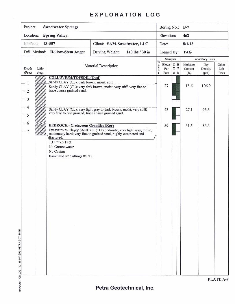
Subsurface Exploration A subsurface exploration program was performed under the direction of an engineering geologist from
Petra on July 30, and August 1, 2013. The exploration involved the advancement of ten (10) exploratory
borings (B-1 through B-10) to a maximum depth of approximately 19.5 feet below existing grades, and/or
practical refusal. The borings were advanced utilizing rubber-tired and track-mounted drill rigs equipped
with 8- and 6-inch diameter hollow-stem augers, respectively. Earth materials encountered within the
exploratory borings were classified and logged by an engineering geologist in accordance with the visual-
manual procedures of the Unified Soil Classification System (USCS), ASTM Test Standard D2488. The
approximate locations of the exploratory borings are shown on Figure 2. The logs for the borings are
presented in Appendix A.
Relatively undisturbed ring and disturbed bulk samples of representative earth materials were collected
from the exploratory borings for classification, laboratory testing and engineering analyses. Undisturbed
samples were obtained using a 3-inch outside diameter modified California split-spoon soil sampler lined
with brass rings. The soil sampler was driven with successive 30-inch drops of a free-fall, 140-pound
automatic trip hammer. The central portions of the driven-core samples were placed in sealed containers
and transported to our laboratory for testing. The number of blows required to drive the split-spoon
sampler 18 inches into the soil were recorded for each 6-inch driving increment; however, the number of
blows required to drive the sampler for the final 12 inches was noted in the boring logs as Blows per Foot.
Laboratory Testing The laboratory testing program included the determination of in-situ dry density and moisture content,
maximum dry density and optimum moisture content, expansion index, direct shear strength, and
preliminary soil corrosivity screening (soluble sulfate and chloride content, pH and minimum resistivity).
A description of laboratory test methods and summaries of the laboratory test data are presented in

SAM-SWEETWATER, LLC September 4, 2013 (Reissued January 19, 2015) 2657 Sweetwater Springs Boulevard/San Diego County J.N. 13-357 Page 4
Appendix B and the in-situ dry density and moisture content results are presented on the boring logs
(Appendix A).
FINDINGS
Regional Geologic Setting The proposed residential development is located within the Peninsular Ranges Geomorphic Provence
(PRGP). The Peninsular Ranges is characterized by steep, elongated ranges and valleys that trend
northwesterly. This province is typified by plutonic and metamorphic rocks (bedrock) which comprise
the majority of the mountain masses, with relatively thin volcanic and sedimentary deposits
discontinuously overlying the bedrock, and with Plio/Pleistocene-age (Quaternary-age) alluvial fan
deposits filling in the valleys and younger alluvium infilling the incised drainages. The alluvial deposits
are derived from the water-borne deposition of the products of weathering and erosion of the bedrock
materials.
Local Geology and Subsurface Soil Conditions More specifically, the subject site lies near the margin of the San Diego Embayment, which is a
downdropped structural block, encompassing the western portion of San Diego County from south of
Carlsbad, east to Rancho Bernardo and south into the northern portion of the Republic of Mexico. The
site is mapped as being underlain by Cretaceous age medium-grained and dark-colored gabbro rock (Tan,
2002). However, based on our recent subsurface field investigations, the site is underlain by Cretaceous
age fine-grained and light-colored granodiorite rock. These granitic rocks are locally mantled by a
relatively thin layer of undocumented artificial fill (believed to be associated with minor grading of the
previous Evergreen Nursery) and near surface colluvium/topsoil materials. In general, the artificial fill,
colluvial/topsoil, and granitic bedrock deposits were generally found to be dry to slightly moist, loose/soft
near the surface, becoming moderately hard with depth.
Groundwater The site is located within the Otay Groundwater Basin, (California Department of Water Resources,
[CDWR], 2010). Groundwater depth varies within the area and though flow direction beneath the subject
site is unknown, however, it is believed to be toward the Sweetwater Reservoir to the southwest. Based

SAM-SWEETWATER, LLC September 4, 2013 (Reissued January 19, 2015) 2657 Sweetwater Springs Boulevard/San Diego County J.N. 13-357 Page 5
on our review, of the CDWR water data library (2013), historic data from nearby wells indicate
groundwater levels range between 8± and 72± feet below the ground surface. No indication of surface
water was observed on the site at the time of this investigation. However, based on our review, the
“Sweetwater Spring” is located down gradient (approximate elevation of 427± MSL) across Sweetwater
Springs Boulevard, approximately 470± feet west of the subject site.
Faulting San Diego County is a seismically active area and several northwest-trending active faults have been
documented within the area. The Rose Canyon and Elsinore fault zones are the most prominent faults
within the San Diego County area. These faults are considered to be “active”. An “active” fault is
defined as a fault that has had displacement within the Holocene epoch, or last ±11,000 years. Based on
our review, the site is not located within an Earthquake Fault Zone, as defined by the state of California in
the Alquist-Priolo Earthquake Fault Zoning Act (Bryant and Hart, 2007).
CONCLUSIONS AND RECOMMENDATIONS
General From a geotechnical engineering and engineering geologic point of view, the subject property is
considered suitable for the proposed residential and commercial development provided the following
conclusions and recommendations are incorporated into the design criteria and project specifications.
Geologic Considerations
Groundwater Based on our review, adverse effects on the proposed development due to shallow regional groundwater
conditions are currently not anticipated. However, seepage and perched groundwater conditions may
occur onsite due to excess irrigation, migration from adjacent springs and/or drainage areas and
developments during and/or after periods of above normal or heavy precipitation. Thus, seepage and
perched water conditions may occur in the future, and should be anticipated. Should manifestations of
seepage and/or perched water conditions develop in the future, Petra could assess the conditions and
provide mitigative recommendations, as necessary.

SAM-SWEETWATER, LLC September 4, 2013 (Reissued January 19, 2015) 2657 Sweetwater Springs Boulevard/San Diego County J.N. 13-357 Page 6
Fault Rupture As discussed previously, the site is not located within a currently designated State of California Alquist-
Priolo Earthquake Fault Zone (Bryant and Hart, 2007). In addition, no known active faults have been
identified on the site. While fault rupture would most likely occur along established fault traces, fault
rupture could occur at other locations. However, the potential for active fault rupture at the site is
considered to be very low.
Seismic Shaking The site is located within an active tectonic area with several significant faults capable of producing
moderate to strong earthquakes. The Rose Canyon, Elsinore, San Jacinto, and San Andreas faults are all
in close proximity to the site and capable of producing strong ground motions.
Secondary Effects of Seismic Activity Secondary effects of seismic activity normally considered as possible hazards to a site include several
types of ground failure, as well as earthquake-induced flooding. Various general types of ground failures,
which might occur as a consequence of severe ground shaking at the site, include ground subsidence,
ground lurching and lateral spreading. The probability of occurrence of each type of ground failure
depends on the severity of the earthquake, distance from faults, topography, subsoil and groundwater
conditions, in addition to other factors. Based on the shallow bedrock materials, site conditions, and
relatively flat topography, ground subsidence ground lurching and lateral spreading is considered unlikely
at the site.
Seismically induced flooding that might be considered a potential hazard to a site normally includes
flooding due to tsunami or seiche (i.e., a wave-like oscillation of the surface of water in an enclosed basin
that may be initiated by a strong earthquake) or failure of a major reservoir or retention structure upstream
of the site. No major reservoir is located upstream of the site. The Sweetwater Reservoir is situated
approximately 1 mile southwest of the site, with an elevation differential greater than approximately 200
feet. Therefore, the potential for seiche or inundation is considered negligible. Because of the inland
location of the site, flooding due to a tsunami is also considered negligible at the site.

SAM-SWEETWATER, LLC September 4, 2013 (Reissued January 19, 2015) 2657 Sweetwater Springs Boulevard/San Diego County J.N. 13-357 Page 7
Landslides and Slope Instability The site exhibits a generally flat topography and no mapped landslides exist within or near the site.
Based on the topography across the site, the potential for landsliding is considered low.
Surface Flooding Based on our review, storm water in the form of localized sheet flooding and/or channelized flows from
adjacent properties has the potential to affect the site. Based on current site configurations (i.e., drainage
channel crossing the site), it is anticipated a drainage study will be performed by the project civil
engineer. As such, the potential for localized surface flooding is considered low.
Expansive Soils Based on the laboratory testing conducted (Appendix B), the Expansion Index (E.I.) of the surface and
subsurface soils across the site are considered to have Medium to Very High expansion potential (i.e., E.I.
between 51 and above 130). Such expansive soils can affect the performance of concrete slabs or
structures with shallow foundations if not properly designed. Therefore, on a preliminary basis
recommendations to mitigate the potential effects of expansive soils will be required during the
foundation design process. Based on the above, post-tension foundations will likely be required since the
Plasticity Index (P.I.) of the onsite soils is greater than >20. Supplemental E.I. and P.I. testing should be
conducted at the conclusion of earthwork to provide final foundation design recommendations, based on
as-graded site soil conditions. Preliminary recommendations for conventional slab-on-ground foundation
in highly expansive soils are also included.
Areal Subsidence The effects of areal subsidence generally occur at the transition or boundaries between low-lying areas
and adjacent hillside terrain, where materials of substantially different engineering properties (i.e.,
alluvium vs. bedrock) are present. Our review of aerial photographs for the site and vicinity indicated no
readily discernable features (i.e., ground fissures, linearity of depressions associated with mountain fronts,
etc.) that would indicate subsidence is occurring at this time. Ground fissures are generally associated
with excessive groundwater withdrawal and associated subsidence, or active faulting. Our review did not
reveal any information that active faulting, ground fissures, or hydro-consolidation in the specific site

SAM-SWEETWATER, LLC September 4, 2013 (Reissued January 19, 2015) 2657 Sweetwater Springs Boulevard/San Diego County J.N. 13-357 Page 8
vicinity, is occurring at this time. Therefore based on the above, and the moderately hard bedrock that
underlies the site, the potential for areal subsidence to affect the site is considered low and would
generally be no greater than that for other existing structures and improvements in the immediate vicinity.
Liquefaction and Seismically-Induced Settlement Assessment of liquefaction potential for a particular site requires knowledge of a number of regional as
well as site-specific parameters, including the estimated design earthquake magnitude, the distance to the
assumed causative fault and the associated probable peak horizontal ground acceleration at the site,
subsurface stratigraphy and soil characteristics. Parameters such as distance to causative faults and
estimated probable peak horizontal ground acceleration can readily be determined using published
references, or by utilizing a commercially available computer program specifically designed to perform a
probabilistic analysis. On the other hand, stratigraphy and soil characteristics can only be accurately
determined by means of a site-specific subsurface investigation combined with appropriate laboratory
analysis of representative samples of onsite soils.
Liquefaction occurs when dynamic loading of a saturated sand or silt causes pore-water pressures to
increase to levels where grain-to-grain contact is lost and material temporarily behaves as a viscous fluid.
Liquefaction can cause settlement of the ground surface, settlement and tilting of engineered structures,
flotation of buoyant buried structures and fissuring of the ground surface. A common manifestation of
liquefaction is the formation of sand boils – short-lived fountains of soil and water that emerge from
fissures or vents and leave freshly deposited conical mounds of sand or silt on the ground surface.
In light of the moderately hard bedrock materials that underlie the site, the potential for manifestation of
liquefaction induced features or settlement is considered nil.
Earthwork
General Earthwork Recommendations Prior to the start of onsite grubbing and earthwork, a meeting should be held at the project with the owner,
contractor, and geotechnical consultant to discuss the work schedule and geotechnical aspects of site
grading. Earthwork should be performed in accordance with the applicable provisions of the 2010 CBC.

SAM-SWEETWATER, LLC September 4, 2013 (Reissued January 19, 2015) 2657 Sweetwater Springs Boulevard/San Diego County J.N. 13-357 Page 9
Grading should also be performed in accordance with the following site-specific recommendations
prepared by Petra based on the proposed residential and commercial development of the site.
Clearing and Grubbing All remaining concrete structures (i.e., foundations, driveways, block walls, etc.), onsite vegetation and/or
mulch (from previous nursery operations), and any trash or debris in areas to be graded should be
removed from the site. During site grading, fill soils should be cleared of any remaining deleterious
materials that were missed during the initial clearing and grubbing operations. Any cavities or
excavations created upon removal of subsurface structures and foundations should be cleared of loose
soil, shaped to provide access for backfilling and compaction equipment, and then backfilled with
properly compacted fill.
The project geotechnical consultant should provide periodic observation and testing services during
clearing and grubbing operations to document compliance with the above recommendations. In addition,
should any unusual or adverse soil conditions be encountered during grading that are not described herein,
these conditions should be brought to the immediate attention of the project geotechnical consultant for
corrective recommendations, as warranted.
Geotechnical Observations and Testing Grading earthwork, which in this instance will generally entail overexcavation and re-compaction of low
density near surface earth materials for structures supported by shallow foundations, should be
accomplished under full-time observation and testing of the geotechnical consultant. A representative of
the project geotechnical consultant should be present onsite during all earthwork operations to document
proper placement and adequate moisture and compaction of fill materials, as well as to document
compliance with the other geotechnical recommendations presented herein.
Ground Preparation – Foundation Areas Based on the earth materials encountered within the exploratory borings, surficial soils (i.e., artificial fill,
colluvium/topsoil, and near surface weathered bedrock) over a majority of the site are loose/very soft to
medium dense/firm, porous, or extremely weathered. Therese materials are considered unsuitable for
support of structures in their existing state, and therefore should be removed and recompacted, in areas

SAM-SWEETWATER, LLC September 4, 2013 (Reissued January 19, 2015) 2657 Sweetwater Springs Boulevard/San Diego County J.N. 13-357 Page 10
proposed for settlement sensitive improvements. In areas where structures are to be supported by
conventional shallow slab-on-grade foundations, spread footings, and/or post-tension foundations the
existing ground should be over-excavated to depths that expose competent bedrock materials exhibiting
an in-place relative compaction of 85 percent or more, based on ASTM Test Method D 1557.
Therefore, the required depths of remedial removals (unsuitable soils) are anticipated to vary from
approximately 2± to 8½± feet. A minimum of three feet of compacted fill should underlie all foundation
elements. The horizontal limits of over-excavation should extend to a minimum distance of 5 feet beyond
the proposed perimeter foundation lines or to a horizontal distance equal to the depth of remedial
removals, whichever is greater.
Due to the variability of the near surface earth materials that underlie the project site, the required depths
of over-excavation will have to be determined during grading on a case-by-case basis. Therefore, prior to
placing compacted fill, the exposed bottom surfaces in all over-excavated areas should be observed and
approved by the project geotechnical consultant. Following this approval, the exposed bottom surfaces
should be scarified to a depth of approximately 6 to 8 inches, watered as necessary to achieve a moisture
content that is equal to or slightly above optimum moisture content, and then processed to a minimum
relative compaction of 90 percent (ASTM D 1557).
Ground Preparation – Cut Areas Cuts that extend to depths greater than approximately 2± to 8½± feet below existing grade are anticipated
to expose competent bedrock materials. However, due to variability in moisture content and the
extremely weathered nature of the bedrock materials encountered across the site, cuts in structural areas
should be overexcavated to a minimum depth of 5 feet, or 3 feet below foundation elements, and replaced
with fill processed to a minimum relative compaction of 90 percent. Shallower removals for roadways
and sheet-graded areas may be appropriate where exposed bedrock materials, following the cut, are
deemed to be suitable as determined by the project engineering geologist and/or geotechnical engineer.
Ground Preparation – Roadways and Sheet-Graded Areas The existing ground in proposed roadway areas to be paved with asphaltic concrete should be over-
excavated and recompacted in a similar manner as recommended above. In areas to be graded to a sheet

SAM-SWEETWATER, LLC September 4, 2013 (Reissued January 19, 2015) 2657 Sweetwater Springs Boulevard/San Diego County J.N. 13-357 Page 11
flow condition for drainage purposes and where no structures are planned, all existing undocumented
artificial fills should be removed, the exposed native earth materials should be scarified to a depth of 8 to
12 inches, watered as necessary to achieve a moisture content that is equal to or slightly above optimum
moisture content, and then compacted in-place to a minimum relative compaction of 90 percent.
Fill Placement and Testing All fill should be placed in lifts not exceeding 6 inches in thickness, watered as necessary to achieve
moisture contents that are equal to, or slightly above optimum moisture content, and then processed to a
minimum relative compaction of 90 percent. Each fill lift should be treated in a similar manner.
Subsequent lifts should not be placed until the preceding lift has been tested and approved by the project
geotechnical consultant. The laboratory maximum dry density and optimum moisture content for each
change in soil type should be determined in accordance with Test Method ASTM D 1557.
Geotechnical Observations The project geotechnical consultant should be present on site during grading operations to observe proper
placement, adequate moisture, and compaction of fill, as well as to document compliance with the other
recommendations presented herein.
Shrinkage and Subsidence Volumetric changes in earth quantities will occur when excavated onsite soils are replaced as properly
compacted fill. Accordingly, it is estimated that a shrinkage factor on the order of approximately 15± to
20± percent will occur when near surface onsite earth materials are excavated and placed as compacted
fill.
Subsidence from scarification and re-compaction of exposed bottom surfaces in over-excavated areas is
expected to be on the order of approximately 0.05 to 0.10 feet.
The above estimates of shrinkage and subsidence are intended as aids for the civil engineer and project
planners in determining earthwork quantities. However, these values should not be considered as
absolute values and some contingencies should be made for balancing earthwork quantities on the basis of
actual shrinkage and subsidence that occur during grading.

SAM-SWEETWATER, LLC September 4, 2013 (Reissued January 19, 2015) 2657 Sweetwater Springs Boulevard/San Diego County J.N. 13-357 Page 12
Foundation Systems General It is our understanding that no project design or grading plans are currently available for the project at this
time. However, building loads are assumed to be typical for this type of relatively light residential and
commercial construction. Therefore, based on the weathered and expansive nature of the bedrock
materials that underlie the site, the proposed residential and commercial structures will likely be founded
on post-tension slab-on-grade foundations systems, although general recommendations for conventional
slab-on-ground foundation are also included. Specific preliminary geotechnical foundation design
recommendations can be provided when actual building loads, site configurations, and rough grading
plans are provided for our review.
Allowable Soil Bearing Capacities A basic allowable soil bearing capacity of 1,500 pounds per square foot, including dead and live loads,
may be utilized for design of 24-inch square pad footing and 12-inch-wide continuous footings founded at
a minimum depth of 12 inches below the lowest adjacent final grade. This value may be increased by 20
percent for each additional foot of depth and by 10 percent for each additional foot of width to a
maximum value of 2,500 pounds per square foot. Recommended allowable bearing values include both
dead and live loads, and may be increased by one-third for short duration wind and seismic forces.
Footing Settlement Based on the allowable bearing values provided above, total settlement of the footings is anticipated to be
less than 1 inch. Differential settlement is expected to be less than 1 inch over a horizontal span of 40
feet. The majority of settlement is likely to take place as footing loads are applied or shortly thereafter.
Lateral Resistance A passive earth pressure of 250 pounds per square foot per foot of depth, to a maximum value of 2,500
pounds per square foot, may be used to determine lateral bearing resistance for footings. In addition, a
coefficient of friction of 0.30 times the dead load forces may be used between concrete and the supporting
soils to determine lateral sliding resistance. The above values may be increased by one-third when
designing for transient wind or seismic forces. It should be noted that the above values are based on the

SAM-SWEETWATER, LLC September 4, 2013 (Reissued January 19, 2015) 2657 Sweetwater Springs Boulevard/San Diego County J.N. 13-357 Page 13
condition where footings are cast in direct contact with compacted fill or competent native soils. In cases
where the footing sides are formed, all backfill placed against the footings upon removal of forms should
be compacted to at least 90 percent of the applicable maximum dry density.
Conventional Slab-on-Ground Foundations As stated above, onsite soils within the subject site should be considered to be expansive per Section
1803.5.3 of the 2010 CBC. Section 1808.6.2 of the 2010 CBC specifies that non-prestressed slab-on-
ground foundations (floor slabs) constructed on expansive materials should be designed in accordance
with the latest edition of the Wire Reinforcement Institute (WRI) publication “Design of Slab-on-Ground
Foundations.” The design procedures outlined in the WRI publication are based on the weighted
plasticity index of the various soil layers existing within the upper 15 feet of the building site. The
recommendations presented herein are to be considered preliminary in nature and subject to modification
following further analysis.
Footings 1. Exterior continuous footings supporting one- and two-story structures should be founded at a
minimum depth of 24 inches below the lowest adjacent final grade. Interior continuous footings may be founded at a minimum depth of 18 inches below the tops of the adjacent floor slabs.
2. All continuous footings should have minimum widths of 12 and 15 inches for one-story and two-
story construction, respectively. All continuous footings should be reinforced with a minimum of four No. 4 bars, two top and two bottom.
3. A 12-inch wide grade beam founded at the same depth as adjacent footings should be provided across
garage entrances. The grade beam should be reinforced in a similar manner as provided above. 4. Interior isolated pad footings, if required, should be a minimum of 24 inches square and founded at a
minimum depth of 18 inches below the top of the adjacent floor slabs. Pad footings should be reinforced with No. 4 bars spaced a maximum of 18 inches on centers, both ways, placed near the bottoms of the footings.
5. Exterior isolated pad footings intended for support of roof overhangs such as second-story decks,
patio covers and similar construction should be a minimum of 24 inches square, and founded at a minimum depth of 24 inches below the lowest adjacent final grade. The pad footings should be reinforced with No. 4 bars spaced a maximum of 18 inches on centers, both ways, placed near the bottoms of the footings. Exterior isolated pad footings may need to be connected to adjacent pad and/or continuous footings via tie beams at the discretion of the project structural engineer.

SAM-SWEETWATER, LLC September 4, 2013 (Reissued January 19, 2015) 2657 Sweetwater Springs Boulevard/San Diego County J.N. 13-357 Page 14
6. The spacing and layout of the interior concrete grade beam system required below floor slabs should be determined by the project architect or structural engineer in accordance with the WRI publication using the effective plasticity index value provided previously.
7. The minimum footing dimensions and reinforcement recommended herein may be modified
(increased or decreased) by the structural engineer responsible for foundation design based on his/her calculations and engineering experience and judgment.
Building Floor Slabs 1. The building pad should be graded such that it accommodates placement of 4 inches of non-
expansive sand and gravel below the slab underlayment system as explained below. 2. Concrete floor slabs should be a minimum 5 inches thick and reinforced with No. 3 bars spaced a
maximum of 15 inches on centers (both ways) for subgrade soils with an effective plasticity index (PI) of less than 20, and with No. 4 bars spaced at a maximum spacing of 20 inches on centers (both ways) for subgrade soils with an effective plasticity index (PI) of 20 or greater. All slab reinforcement should be supported on concrete chairs or brick to ensure the desired placement near mid-depth.
3. Living area concrete floor slabs should be underlain with a moisture vapor retarder consisting of a
minimum 10-mil-thick polyethylene or polyolefin membrane that meets the minimum requirements of ASTM E96 and ASTM E1745 for vapor retarders (such as Husky Orange Guard®, Stego® Wrap, or equivalent). All laps within the membrane should be sealed, and at least 2 inches of clean sand should be placed over the membrane to promote uniform curing of the concrete. To reduce the adverse impact of highly expansive soils on slab performance, a 4-inch non-expansive layer of sand and gravel should be placed below the moisture vapor retarder membrane.
At the present time, some slab designers, geotechnical professionals and concrete experts view the sand layer below the slab (blotting sand) as a place for entrapment of excess moisture that could adversely impact moisture-sensitive floor coverings. As a preventive measure, the potential for moisture intrusion into the concrete slab could be reduced if the concrete is placed directly on the vapor retarder. However, if this sand layer is omitted, appropriate curing methods must be implemented to ensure that the concrete slab cures uniformly. A qualified materials engineer with experience in slab design and construction should provide recommendations for alternative methods of curing and supervise the construction process to ensure uniform slab curing. Additional steps would also need to be taken to prevent puncturing of the vapor retarder during concrete placement.
4. Garage floor slabs should be a minimum 5 inches thick and reinforced in a similar manner as living
area floor slabs. Garage slabs should also be poured separately from adjacent wall footings with a positive separation maintained using ¾-inch-minimum felt expansion joint materials. To control the propagation of shrinkage cracks, garage floor slabs should be quartered with weakened plane joints.

SAM-SWEETWATER, LLC September 4, 2013 (Reissued January 19, 2015) 2657 Sweetwater Springs Boulevard/San Diego County J.N. 13-357 Page 15
5. Prior to placing concrete, the subgrade soils below living area floor slabs should be pre-watered to achieve a moisture content that is at least 1.4 times the optimum moisture content. This moisture should penetrate to a depth of approximately 24 inches into the subgrade.
6. The minimum dimensions and reinforcement recommended herein for building floor slabs may be
modified (increased or decreased) by the structural engineer responsible for foundation design based on his/her calculations, engineering experience and judgment.
Post-Tensioned Slab-on-Ground Foundations
As stated above, onsite soils within the subject site should be considered to be expansive per Section
1803.5.3 of the 2010 CBC. Section 1808.6.2 of the 2010 CBC specifies that post-tensioned slab-on-
ground foundations (floor slabs) resting on expansive materials should be designed in accordance
with the latest edition of the Post-Tensioning Institute (PTI) publication “Standard Requirements
for Design of Shallow Post-Tensioned Concrete Foundations on Expansive Soils.”
To comply with Section 1808.6.2 of the 2010 CBC and the PTI publication, in addition to performing
appropriate tests on preliminary samples of site soils, certain assumptions regarding the site
environmental condition and the composition of the subsurface soils were made. The following table
provides preliminary soil and environmental parameters for design of post-tensioned slabs-on-grade based
on our laboratory testing, engineering analysis as well as our engineering judgment and experience on
similar sites. The recommendations presented herein are to be considered preliminary in nature and
subject to modification following further analysis.

SAM-SWEETWATER, LLC September 4, 2013 (Reissued January 19, 2015) 2657 Sweetwater Springs Boulevard/San Diego County J.N. 13-357 Page 16
Design Parameters for PTI Procedure
Soil Information
Liquid Limit (LL) 55 Plastic Limit (PL) 16 Plasticity Index (PI) 39 Percent Passing No. 200 Sieve (% < #200) 90 Percent Less than 2 Microns (% < 0.002 mm) 80 Expansion Index (EI) 138
Summary of Design Parameters
Approximate Depth of Constant Suction, feet 9 Approximate Soil Suction, pF 3.9 Thornthwaite Index: -20 Average Edge Moisture Variation Distance, em in feet:
Center Lift Edge Lift
7.6 4.0
Anticipated Swell, ym in inches: Center Lift Edge Lift
0.441 1.071
Modulus of Subgrade Reaction The modulus of subgrade reaction for design of load bearing partitions may be assumed to be 80 pounds
per cubic inch.
Minimum Design Recommendations The soil values provided above may be utilized by the project structural engineer to design post-tensioned
slabs-on-ground in accordance with Section 1808.6.2 of the 2010 CBC and the PTI publication. Thicker
floor slabs and larger footing sizes may be required for structural reasons and should govern the design if
more restrictive than the minimum recommendations provided below:
1. Perimeter footings for both one-story and two-story structures should be founded at a minimum depth
of 21 inches below the lowest adjacent finished ground surface. Interior footings may be founded at a minimum depth of 15 inches below the tops of the finish floor slabs. All continuous footings should be reinforced with a minimum of four No. 4 bars, two top and two bottom.
2. A minimum 12-inch-wide grade beam founded at the same depth as adjacent footings should be provided across the garage entrances. The grade beam should be reinforced in a similar manner as provided above.

SAM-SWEETWATER, LLC September 4, 2013 (Reissued January 19, 2015) 2657 Sweetwater Springs Boulevard/San Diego County J.N. 13-357 Page 17
3. Exterior isolated pad footings intended for support of roof overhangs such as second-story decks, patio covers and similar construction should be a minimum of 24 inches square, and founded at a minimum depth of 24 inches below the lowest adjacent final grade. The pad footings should be reinforced with No. 4 bars spaced a maximum of 18 inches on centers, both ways, placed near the bottoms of the footings. Exterior isolated pad footings may need to be connected to adjacent pad and/or continuous footings via tie beams at the discretion of the project structural engineer.
4. The thickness of the floor slabs should be determined by the project structural engineer with
consideration given to the expansion potential of the on-site soils, however; we recommend that a minimum slab thickness of 5 inches be considered.
5. As an alternative to designing 5-inch-thick post-tensioned slabs with perimeter footings as described
in Items 1 and 2 above, the structural engineer may design the foundation system using a thickened slab design. The minimum thickness of this uniformly thick slab should be 12 inches. The engineer in charge of post-tensioned slab design may also opt to use any combination of slab thickness and footing embedment depth as deemed appropriate based on their engineering experience and judgment. .
6. Living area concrete floor slabs should be underlain with a moisture vapor retarder consisting of a
minimum 10-mil-thick polyethylene or polyolefin membrane that meets the minimum requirements of ASTM E96 and ASTM E1745 for vapor retarders (such as Husky Orange Guard®, Stego® Wrap, or equivalent). All laps within the membrane should be sealed, and at least 2 inches of clean sand should be placed over the membrane to promote uniform curing of the concrete. To reduce the potential for punctures, the membrane should be placed on a pad surface that has been graded smooth without any sharp protrusions. If a smooth surface cannot be achieved by grading, consideration should be given to lowering the pad finished grade an additional inch and then placing a 1-inch-thick leveling course of sand across the pad surface prior to the placement of the membrane.
At the present time, some slab designers, geotechnical professionals and concrete experts view the sand layer below the slab (blotting sand) as a place for entrapment of excess moisture that could adversely impact moisture-sensitive floor coverings. As a preventive measure, the potential for moisture intrusion into the concrete slab could be reduced if the concrete is placed directly on the vapor retarder. However, if this sand layer is omitted, appropriate curing methods must be implemented to ensure that the concrete slab cures uniformly. A qualified materials engineer with experience in slab design and construction should provide recommendations for alternative methods of curing and supervise the construction process to ensure uniform slab curing. Additional steps would also need to be taken to prevent puncturing of the vapor retarder during concrete placement.
7. Presaturation of the subgrade below floor slabs will not be required; however, prior to placing
concrete, the subgrade below all dwelling and garage floor slab areas should be thoroughly moistened to achieve a moisture content that is at least equal to or slightly greater than optimum moisture content to a minimum depth of 24 inches below the bottoms of the slabs.

SAM-SWEETWATER, LLC September 4, 2013 (Reissued January 19, 2015) 2657 Sweetwater Springs Boulevard/San Diego County J.N. 13-357 Page 18
General Corrosivity Screening The following sections represent an interpretation of current codes and specifications that are commonly
used in our industry as they relate to the adverse impact of chemical components of the site soils on
various components of the proposed structures. As a screening level study, limited chemical testing was
performed on representative samples of onsite soils to identify potential corrosive characteristics of these
soils. A variety of test methods are available to quantify the corrosive potential of soils. The testing
procedures referred to herein are considered to be typical for our industry and have been adopted and/or
approved by many public or private agencies.
Petra does not practice corrosion engineering; therefore, the opinion and engineering judgment provided
herein should be considered as general guidelines only. Further analyses would be warranted for cases
where buried metallic building materials such as copper and ductile iron are planned for the project. For
these conditions, we recommend that the project design professionals (i.e., the architect and/or structural
engineer) consider recommending a qualified corrosion engineer to conduct additional sampling and
testing of near-surface soils during the final stages of site grading to provide a complete assessment of
soil corrosivity. Recommendations to mitigate the detrimental effects of corrosive soils on buried
metallic and other building materials that may be exposed to corrosive soils should be provided by the
corrosion engineer, as deemed appropriate.
Concrete in Contact with Site Soils Soils containing soluble sulfates beyond certain threshold levels as well as acidic soils are considered to
be detrimental to integrity of concrete placed in contact with such soils. For the purpose of this study,
soluble sulfates concentration in soils determined in accordance with California Test Method No. 417.
Soil acidity, as indicated by hydrogen-ion concentration (pH), was determined in accordance with
California Test Method No. 643.
The results of our laboratory tests indicate that on-site soils within the subject site contain a water soluble
sulfate contents of between 0.06 and 0.12 percent by weight. Based on Section 1904.3 of the 2010 CBC,
concrete that will be exposed to sulfate-containing soils should comply with the provisions of Section 4.3
of ACI 318.

SAM-SWEETWATER, LLC September 4, 2013 (Reissued January 19, 2015) 2657 Sweetwater Springs Boulevard/San Diego County J.N. 13-357 Page 19
According to Table 4.2.1 of ACI 318-08 (a precursor to Section 4.3), an exposure class of S0 to S1 is
considered appropriate for onsite soils. As such, a range of Not Applicable to Moderate exposure to
sulfate may be expected for concrete placed in contact with the onsite soil materials. As directed by
Table 4.3.1 of ACI 318-08, no restriction for cement or maximum water-cement ratio for the fresh
concrete would be required for an exposure class of S0. For this exposure class, the concrete minimum
unconfined compressive strength should not be less than 2,500 psi. Per Table 4.3.1, a maximum water-
cement ratio of 0.50 for the fresh concrete would be required for an exposure class of S1. For this
exposure class the concrete minimum unconfined compressive strength should not be less than 4,000 psi.
The S1 exposure class should be considered for design purposes.
The results of limited in-house testing of representative samples indicate that soils within the subject site
are neutral with respect to pH (pH of 7.1 and 7.2). Based on this finding and according to Section 8.22.2
of Caltrans’ 2003 Bridge Design Specifications (2003 BDS) requirements (which consider the combined
effects of soluble sulfates and soil pH), a commercially available Type II Modified cement may be used.
These recommendations should be verified by the project structural engineer and the contractor
responsible for concrete placement for concrete used in footings and interior slabs-on-ground, foundation
walls and concrete exposed to weather.
Metals Encased in Concrete Soils containing a soluble chloride concentration beyond a certain threshold level are considered
corrosive to metallic elements such as reinforcement bars, cables, bolts, etc. that are encased in concrete
that, in turn, is in contact with such soils. For the purpose of this study, soluble chlorides in soils were
determined in accordance with California Test Method No. 422.
The results of limited screening tests performed indicate that onsite soils contain a water-soluble chloride
concentrations of between 83 and 122 parts per million (ppm). Section 1904.4 of CBC 2010 requires that
reinforcement in concrete be protected from the corrosive effects of chloride exposure in accordance with
Section 4.4 of ACI 318. It should be noted that Section 4.4 of ACI 318-08 pertains to freeze-and-thaw
conditions that are not applicable to the subject project; however, regardless of the level of chlorides in
soils in contact with concrete, Table 4.2.1 of ACI 318-08 assigns an exposure class of C1 for concrete that

SAM-SWEETWATER, LLC September 4, 2013 (Reissued January 19, 2015) 2657 Sweetwater Springs Boulevard/San Diego County J.N. 13-357 Page 20
will be exposed to moisture but not necessarily to external sources of chlorides. As such, a Moderate
exposure to chloride may be expected for metallic elements encased in concrete, which is, in turn, placed
in contact with the onsite soil materials.
One method of protecting reinforcement in concrete where moderate chloride concentrations are present
in the soils is to increase the thickness of the concrete cover over the reinforcement. However, Table
8.22.1 of Caltrans BDS 2003 provides no minimum concrete cover when chloride concentration is less
than 500 ppm (as is the case for the subject site). This recommendation should be verified by the project
structural engineer.
Metallic Elements in Contact with Site Soils Elevated concentrations of soluble salts in soils tend to induce low level electrical currents in metallic
objects in contact with such soils. This process promotes metal corrosion and can lead to distress to
building components that are in contact with site soils. The minimum electrical resistivity indicates the
relative concentration of soluble salts in the soil and, therefore, can be used to estimate soil corrosivity
with regard to metals. For the purpose of this investigation, the minimum resistivity in soils is measured
in accordance with California Test Method No. 643.
The minimum electrical resistivity for onsite soils was found to be between 640 and 1,000 ohm-cm based
on limited testing. This result indicates that on-site soils are Severely Corrosive to Corrosive to ferrous
metals and copper. As such, any ferrous metal or copper components of the subject buildings or panel
foundations that are expected to be placed in direct contact with site soils should be protected against
detrimental effects of the corrosive soils.
Post-Grading Recommendations
Site Drainage Positive-drainage devices, such as sloping flatwork, graded-swales and/or area drains, should be provided
around buildings to collect and direct water away from the structures. Neither rain nor excess irrigation
water should be allowed to collect or pond against building foundations. Drainage should be directed to
an appropriate discharge area. The ground surface adjacent to the structures should also be sloped at a
gradient of 2 percent or more away from the foundations for a horizontal distance of 5 feet or more.

SAM-SWEETWATER, LLC September 4, 2013 (Reissued January 19, 2015) 2657 Sweetwater Springs Boulevard/San Diego County J.N. 13-357 Page 21
Utility Trenches Utility-trench backfill materials to be placed within access roads, utility easements, cable raceways, and
under building-floor slabs should be compacted to a relative compaction of 90 percent or more. Where
onsite soils are utilized as backfill, mechanical compaction methods should be utilized. Density testing,
along with probing, should be performed by the project geotechnical consultant or his representative to
document adequate compaction.
Utility-trench sidewalls deeper than about 3 feet should be laid back at a ratio of 1:1 horizontal to vertical
(h:v) or flatter, or shored. A trench box may be used in lieu of shoring. If shoring is anticipated, the
project geotechnical consultant should be contacted to provide appropriate design parameters.
For trenches with vertical walls, backfill should be placed in approximately 1- to 2-foot thick loose lifts
and then mechanically compacted with a hydra-hammer, pneumatic tampers, sheepsfoot roller, or similar
compaction equipment. For deep trenches with sloped walls, backfill materials should be placed in
approximately 8- to 12-inch-thick loose lifts and then compacted by rolling with a sheepsfoot tamper, a
full rubber-tired loader, or similar compaction equipment.
Where utility trenches are proposed in a direction that parallels any structural footing (interior and/or
exterior trenches), the bottom of the trench should not be located within a 1:1 (h:v) plane projected
downward from the outside bottom edge of the adjacent footing.
PLAN REVIEW AND CONSTRUCTION SERVICES
This report has been prepared for the exclusive use of SAM-Sweetwater, LLC to assist the project team in
the design of the proposed development. It is recommended that Petra be engaged to review the final-
design drawings and specifications prior to construction. This is to document that the recommendations
contained in this report have been properly interpreted and are incorporated into the project grading plans
and specifications. If Petra is not accorded the opportunity to review these documents, we can take no
responsibility for misinterpretation of our recommendations.
We recommend that Petra be retained to provide soil-engineering services during grading and
construction of the excavation and foundation preparation phases of the work. This is to observe

SAM-SWEETWATER, LLC September 4, 2013 (Reissued January 19, 2015) 2657 Sweetwater Springs Boulevard/San Diego County J.N. 13-357 Page 22
compliance with the design, specifications, or recommendations and to allow design changes in the event
that subsurface conditions differ from those anticipated prior to start of construction.
If the project design concept changes significantly (e.g., structural loads or types), we should be retained
to review our original design recommendations and their applicability to the revised construction concept.
If conditions are encountered during construction that appears to be different than those indicated in this
report, this office should be notified immediately. If this is the case, design and construction revisions
may be required.
LIMITATIONS
This report is based on the project, as described, and the preliminary geologic/geotechnical field data
obtained from the limited field tests performed at the locations shown. The materials encountered on the
project site and utilized in our laboratory evaluation are believed representative of the total area, and the
conclusions and recommendations contained in this report are presented on that basis. However, soil
materials and groundwater levels can vary in characteristics between points of excavation, both laterally
and vertically.
The conclusions and opinions contained in this report are based on the results of the described
geotechnical evaluations and represent our professional judgment. The contents of this report are
professional opinions and as such, are not to be considered a guaranty or warranty. The findings,
conclusions and opinions contained in this report are to be considered tentative only and subject to
confirmation by the undersigned during the construction process. Without this confirmation, this report is
to be considered incomplete and Petra or the undersigned professionals assume no responsibility for its
use. In addition, this report should be reviewed and updated after a period of 1 year or if the site
ownership or project concept changes from that described herein.
The professional opinions contained herein have been derived in accordance with current standards of
practice and no warranty is expressed or implied. This report has not been prepared for use by parties or
projects other than those named or described herein. This report may not contain sufficient information
for other parties or other purposes.

SAM-SWEETWATER, LLC September 4, 2013 (Reissued January 19, 2015) 2657 Sweetwater Springs Boulevard/San Diego County J.N. 13-357 Page 23
We sincerely appreciate this opportunity to be of service. Please do not hesitate to call the undersigned if
you have any questions regarding this report.
Respectfully submitted,
PETRA GEOSCIENCES, INC.
Todd Greer, CEG Grayson R. Walker, GE Senior Project Geologist Principal Engineer CEG 2377 GE 871

SAM-SWEETWATER, LLC September 4, 2013 (Reissued January 19, 2015) 2657 Sweetwater Springs Boulevard/San Diego County J.N. 13-357
REFERENCES American Concrete Institute, 2004, ACI Manual of Concrete Practice, Part 3 – 2004. Bryant and Hart, E.W., W.A., 2007, Fault-rupture hazard zones in California, Alquist-Priolo earthquake
fault zoning act with index to earthquake fault zones maps; California Geological Survey, Special Publication 42, interim revision.
California Building Standards Commission, 2010, California Building Code, California Code of
Regulations, Title 24, Part 2, Volume 2 of 2, Based on the 2009 International Building Code, 2010 California Historical Building Code, Title 24, Part 8; 2010 California Existing Building Code, Title 24, Part 10.
California Department of Transportation, 2006, Standard Specifications, dated July. California Department of Water Resources, 2013, Water Data Library,
http://www.water.ca.gov/waterdatalibrary/groundwater/. _____, 2004, California Groundwater - Bulletin 118. California Division of Mines and Geology, 1992, Geologic Map of California, Olaf P. Jenkins Edition,
Santa Ana Sheet, 1:250,000 scale. California Geological Survey, 2002, Probabilistic Seismic Hazard Assessment for the State of California,
Open-File Report 96-08, Revised 2002 California Seismic Shaking Analysis, , Appendix A. _____, 2008, Special Publication 117A ______, 2011, California Geological Survey Website:
http//www.consrv.gov/CGS/rghm/Pshamap/pshamain.html International Association of Plumbing & Mechanical Officials, 2009, Uniform plumbing code: Walnut,
California. Ishihara, K. (1985), Stability of Natural Deposits During Earthquakes, 11th International Conference on
Soil Mechanics and Foundation Engineering, Procedings, San Francisco, Vol. 1., pp. 321-376. Jennings, C.W. and Bryant, W.A., 2010, Fault Activity Map of California: California Geological Survey,
Geologic Data Map No. 6. Jennings, C.W, 2010, Geologic Map of California: California Geological Survey, Geologic Data Map No.
2. Moss Et. Al. (2006), CPT-Based Probabilistic Assessment of Seismic Soil Liquefaction Initiation, Pacific
Earthquake Engineering Research Center, PEER 2005/15, April 2006.

SAM-SWEETWATER, LLC September 4, 2013 (Reissued January 19, 2015) 2657 Sweetwater Springs Boulevard/San Diego County J.N. 13-357
Petersen, M.D. et al, 1996, Probabilistic Seismic Hazard Assessment for the State of California: California Division of Mines and Geology, Open-File Report 96-08.
Petersen, M.D., and Wesnouski, S.G., 1994, Fault Slip Rates and Earthquake Histories in Southern California: Bulletin of the Seismological Society of America, Vol. 84, No. 5, pp. 1608-1649, October, 1994.
Salgado, Rodrigo, 2006, The Engineering of Foundations. Standard Specifications for Public Works Construction (Greenbook), 2009, BNI Publishers. Southern California Earthquake Center (SCEC, 1998), Seismic Hazards in Southern California: Probable
Earthquakes, 1994 to 2024: by Working Group on California Earthquake Probabilities. Southern California Earthquake Center (SCEC, 1999), Recommended Procedures for Implementation of
DMG Special Publication 117, Guidelines for Analyzing and Mitigating Liquefaction Hazards in California: organized through the Southern California Earthquake Center, University of Southern California.
Tan, Siang S. 2002, Geologic Map of the Jamul Mountain 7.5’ Quadrangle, San Diego County,
California, California Geologic Survey, Scale 1:24,000. United States Geologic Survey, 2013, 2008 Earthquake Hazards Program, 2008 Interactive
Deaggregations (Beta), Earthquake Hazards Program; http://eqint.cr.usgs.gov/deaggint/2008/. _____, 2008, Seismic Hazard Curves and Uniform Response Spectra, Version 5.0.9. _____, 1996a, Probabilistic Seismic Hazard Assessment for the State of California, Open-File Report 96-
706.


SAM-SWEETWATER, LLC September 4, 2013 (Reissued January 19, 2015) 2657 Sweetwater Springs Boulevard/San Diego County J.N. 13-357
APPENDIX B
Laboratory Test Criteria Soil Classification
Soils encountered within the exploratory borings were initially classified in the field in general accordance with the visual-manual procedures of the Unified Soil Classification System (ASTM D2488). The samples were re-examined in the laboratory and the classifications reviewed and then revised where appropriate. The assigned group symbols are presented in the Boring Logs (Appendix A). In-Situ Moisture and Density
Moisture content and unit dry density of in-place soils were determined in representative strata. Test data are summarized in the Boring Logs (Appendix A). Maximum Dry Density
Maximum dry density and optimum moisture content were determined for selected samples of the onsite soils in general accordance with ASTM D1557. The test results are presented on Plate B-1. Expansion Index
Expansion Index (E.I.) testing was performed on a selected bulk samples of the onsite soils in general accordance with ASTM D4829. The expansion potential classification was determined from 2010 CBC Section 1802.3.2 on the basis of the E.I. value. The test results and expansion potentials are presented on Plate B-1. Atterberg Limits
Atterberg limit tests (Liquid Limit, Plastic Limit and Plasticity Index) were performed on selected samples to verify visual classifications. These tests were performed in accordance with ASTM D4318. Test results are presented on Plate B-1. Corrosivity
Chemical analyses were performed on a selected sample of the onsite soils to determine concentrations of soluble sulfate and chloride, as well as pH and resistivity. The tests were performed in general accordance with California Test Method Nos. 417 (sulfate), 422 (chloride) and 643 (pH and resistivity). Test results are included on Plate B-2. Direct Shear
The Coulomb shear strength parameters, angle of internal friction and cohesion, were determined for disturbed (bulk) samples remolded to approximately 90 percent of maximum dry density. These tests were performed in general accordance with ASTM D3080. Three specimens were prepared for each test. The test specimens were artificially saturated, and then sheared under varied normal loads at a maximum constant rate of strain of 0.01 inches per minute. Results are graphically presented on Plates B-3 and B-4.

SAM-SWEETWATER, LLC September 4, 2013 (Reissued January 19, 2015) 2657 Sweetwater Springs Boulevard/San Diego County J.N. 13-357
Plate B-1
APPENDIX B
MAXIMUM DRY DENSITY
Boring/Depth
(feet) Soil Type
Maximum Dry
Density1
(pcf)
Optimum Moisture1
(%)
B-4 @ 0-5 Clayey SAND (SC) 111.0 16.0
B-7 @ 0-4 Clayey SAND (SC) 115.0 16.0
EXPANSION INDEX
Boring/Depth
(feet) Soil Type Expansion Index2 Expansion Potential3
B-1 @ 1-5 Sandy Clay (CL) 84 Medium
B-4 @ 0-5 Clayey Sand (SC) 57 Medium
B-7 @ 0-4 Clay (CH) 138 Very High
ATTERBURG LIMITS TEST DATA
Boring/Depth
(feet) Liquid Limit4 Plastic Limit4
Plasticity
Index4 USCS Classification
B-1 @ 1-5 52 16 36 CH (High-Plasticity Clay)
B-4 @ 0-5 48 16 32 CL (Low-Plasticity Sandy Clay)
B-7 @ 0-4 55 16 39 CH (High-Plasticity Clay)

SAM-SWEETWATER, LLC September 4, 2013 (Reissued January 19, 2015) 2657 Sweetwater Springs Boulevard/San Diego County J.N. 13-357
Plate B-2
APPENDIX B
CORROSIVITY
Boring/Depth
(feet)
Sulfate5
(%)
Chloride6
(ppm) pH7
Resistivity7
(ohm-cm) Corrosivity Potential
B-4 @ 1-5 0.12 122 7.1 640 Concrete: Negligible Steel: Severely Corrosive
B-10 @ 4-8 0.06 83 7.2 1,000 Concrete: Negligible Steel: Corrosive
(1) PER ASTM D 1557 (2) PER ASTM D 4829 (3) PER 2010 CBC SECTION 1802.3.2 (4) PER ASTM D 4318 (5) PER CALIFORNIA TEST METHOD NO. 417 (6) PER CALIFORNIA TEST METHOD NO. 422 (7) PER CALIFORNIA TEST METHOD NO. 643


