sda bulk cover clean - lloyd's register · primary structure of bulk carriers, may 2004...
TRANSCRIPT

Structural DesignAssessment
Primary Structure of BulkCarriers
Guidance on direct calculations
May 2004
ShipRightDesign and construction

ABCD Lloyd’s Register Marine Business Stream 71 Fenchurch Street London EC3M 4BS Telephone 020 7709 9166 Telex 888379 LR LON G Fax 020 7488 4796
Lloyd's Register, its affiliates and subsidiaries and their respective officers, employees or agents are, individually and collectively, referred to in this clause as the ‘Lloyd's Register Group’. The Lloyd's Register Group assumes no responsibility and shall not be liable to any person for any loss, damage or expense caused by reliance on the information or advice in this document or howsoever provided, unless that person has signed a contract with the relevant Lloyd's Register Group entity for the provision of this information or advice and in that case any responsibility. Lloyd’s Register Marine Business Stream is a part of Lloyd’s Register.
Lloyd’s Register,2004
Document History
Document Date: Notes:
July 2002 Revised Document
Notice 1 October 2002
Revisions as identified in ‘ History of Development up to January 2004’
Notice 4 July 2003
Revisions as identified in ‘ History of Development up to January 2004’
May 2004 Revisions as identified in ‘Structural Design Assessment – Primary structure of Bulk Carriers, Changes incorporated in May 2004 version’.
Primary Structure of Bulk Carriers, May 2004
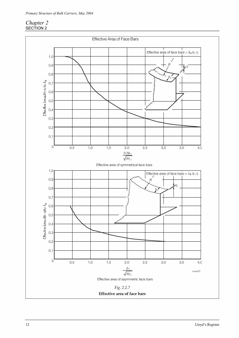
Contents
Lloyd's Register i
Contents
Chapter 1 Introduction 1 Section 1 Application 1 2 Symbols 3 3 Design Calculation Procedure Report 4
Chapter 2 Primary Structure of Bulk Carriers 5 Section 1 Objectives 5 2 Structural modelling 5
3 Boundary conditions 14 3.1 General 14 3.2 Boundary conditions for application of symmetry 14 3.3 Boundary conditions for application of local loads 14 3.4 Boundary conditions for application of global loads 15 4 Loading conditions 17 5 Stress acceptance criteria 32 6 Buckling acceptance criteria 36 7 Cargo loads 40 8 Hold mass curves 42

Primary Structure of Bulk Carriers, May 2004
Chapter 1 SECTION 1
Lloyd's Register 1
Introduction
Section 1: Application
Section 2: Symbols Section 3: Design Calculation Procedure Report ■ Section 1: Application 1.1 The ShipRight Structural Design Assessment (SDA) procedure is mandatory for bulk carriers equal to and greater than 190 m in Rule length and for other bulk carriers of abnormal hull form, or of unusual structural configuration or complexity. 1.2 For bulk carriers, other than those defined in 1.1, the SDA and CM procedures may be applied on a voluntary basis. 1.3 When applied on a mandatory basis, the SDA procedure must be utilised in conjunction with ShipRight Fatigue Design Assessment (FDA) and Construction Monitoring (CM) procedures. The application of the procedures in this way ensures that:
The critical areas are identified early in the design phase. The structural details are designed to minimise the inclusion of stress concentrations. The steelweight distribution is better targeted to the important structural areas. Appropriate construction tolerances are applied to critical areas during construction which reflect the
increased diligence and care taken during the design stage. The Shipowner’s commitment to safety is demonstrated.
1.4 The minimum requirements specified in this procedure, in addition to the requirements in Lloyd’s Register’s Rules and Regulations for the Classification of Ships (hereafter referred to as the Rules for Ships), are to be complied with. 1.5 The SDA procedure requires:
A detailed analysis of the ship’s structural response to applied static and dynamic loads, using three-dimensional (3-D) finite element analysis.
Assessment of the strength of the ballast hold boundaries against collapse due to the dynamic loads imposed by sloshing where it is intended to carry ballast water in partially filled holds at sea. See Lloyd’s Register’s ShipRight SDA procedure Sloshing loads and scantling assessment.
Other direct calculations as applicable.

Primary Structure of Bulk Carriers, May 2004
Chapter 1 SECTION 1
2 Lloyd’s Register
1.6 The structural model and load cases, detailed in Chapter 2, will enable the following structural responses to be investigated: • Stresses in longitudinal primary members resulting from both local and hull girder loads • Stresses in transverse primary members including transverse bulkheads • Buckling capability of plate panels of primary structures. 1.7 This document details the SDA procedure for carrying out a 3-D model finite element analysis of the primary structures of cargo holds. 1.8 A detailed report of the SDA analysis is to be submitted and must include information detailed in Sec. 3.1. The report must show compliance with the specified acceptance criteria given in Chapter. 2, Sections 5 and 6 of this document. 1.9 If the computer programs employed are not recognised by Lloyd’s Register, then full particulars of the programs are to be submitted. See Pt 3, Ch 1,3.1 of the Rules for Ships. 1.10 Lloyd’s Register may, in certain circumstances, require submission of the computer input and output in a suitable electronic format to further verify adequacy of the calculations carried out. 1.11 Where alternative procedures are proposed, these are to be agreed with Lloyd’s Register before commencement. 1.12 Bulk carriers of unusual form or structural arrangements may need special consideration and additional calculations to those shown in this SDA procedure. 1.13 It is recommended that the designer consults with Lloyd’s Register on the structural analysis requirements of the SDA procedure at an early stage in the design cycle.
Primary Structure of Bulk Carriers, May 2004
Chapter 1 SECTION 2
Lloyd's Register 3
■ Section 2: Symbols 2.1 The symbols used in the SDA procedure, in Chapter 2, are defined as follows:
L = Rule ship length, in metres, as defined in Pt 3, Ch 1,6 of the Rules for Ships B = moulded ship breadth, in metres, as defined in Pt 3, Ch 1,6 of the Rules for Ships D = ship depth, in metres, as defined in Pt 3, Ch 1,6 of the Rules of Ships Tsc = scantling draught, in metres Ta = actual draught, in metres, in a loading condition Tbd = deepest draught, in metres, in relevant ballast conditions envisaged Tbs = shallowest draught, in metres, in relevant ballast conditions envisaged using hold ballasting but
excluding ballast water exchange conditions Mwh = Rule hogging wave bending moment; see Pt 3, Ch 4,5 of the Rules for Ships Mws = Rule sagging wave bending moment; see Pt 3, Ch 4,5 of the Rules for Ships Msh = hogging maximum permissible still water bending moment Mss = sagging maximum permissible still water bending moment Ma = actual still water bending moment in a loading condition Mh = actual cargo mass in a cargo hold corresponding to a homogeneously loaded condition at scantling
draught. The density of cargo corresponds to that being fully filled to top of hatch coaming Mfull = cargo mass in a cargo hold corresponding to cargo with virtual density (cargo mass/hold cubic
capacity, minimum 1,0 tonne/m3) filled to top of hatch coaming. Mfull is in no case to be less than Mh. For BC-A and BC-B notation, the density of cargo is to be taken as 3,0 tonnes/m3. The density less than 3,0 tonnes/m3 may be acceptable in conjunction with the proposed ship’s notation. For BC-C notation, the density of cargo is to be not less than or equal to 1,0 tonne/m3 but in no case is Mfull to be taken less that of Mh
Mhd = maximum cargo mass allowed to be carried in a cargo hold under alternate ore loading conditions. The density of heavy ore is to be taken as 3, tonnes/m3. The density less than 3, tonnes/m3 may be acceptable in conjunction with the proposed ship’s notation. The cargo density is also applicable to the additional cargo weight of 0,1Mh indicated in the loading Tables of Ch 2,4. With respect to light ore , see the cargo density definition of Alt. 3 of Table 2.4.2(e-2) in Chapter 2
Mblk = maximum cargo mass allowed to be carried in a cargo hold under block ore loading conditions. The density of heavy ore is to be taken as 3,0 tonnes/m3. The density less than 3,0 tonnes/m3 may be acceptable in conjunction with the proposed ship’s notation. The cargo density is also applicable to the additional cargo weight of 0,1Mh indicated in the loading Tables of Ch 2,4
ρ = density of sea water (specific gravity to be taken as 1,025). ρc = density of cargo kL = higher tensile steel factor, see Pt 3, Ch 2,1.2 of the Rules for Ships σo = specified minimum yield stress, see Pt 3, Ch 2,1.2 of the Rules for Ships. Special consideration will be
given to the steel of σo ≥ 355 N/mm2 σe =
= Von Mises equivalent stress (σx2 + σy2 - σx σy + 3 τxy2)0.5
σx = direct stress in element x direction σy = direct stress in element y direction τxy = shear stress in element xy plane
λ = =
required factor against plate panel buckling σcr/σa
σcr = critical equivalent buckling stress σa = equivalent applied stress
2.2 Consistent units are to be used throughout all parts of the analysis. Results presentation in N and
mm are preferred. 2.3 All Rule equations are to be use units as defined in the Rules for Ships.

Primary Structure of Bulk Carriers, May 2004
Chapter 1 SECTION 3
4 Lloyd’s Register
■ Section 3: Direct calculation procedure report 3.1 A report is to be submitted to Lloyd’s Register for approval of the primary structures in the cargo region and is to contain the following items: • List of plans used including dates and versions. • Detailed description of structural modelling including all modelling assumptions. • Plots to demonstrate correct structural modelling and assigned properties. • Details of material properties used. • Details of boundary conditions. • Details of all loading conditions reviewed with calculated SF and BM distributions. • Details of applied loads and confirmation that individual and total loads are correct. • Plots and results that demonstrate correct behaviour of the structural model to applied loads. • Summaries and plots of global/local deflections. • Summaries and sufficient plots of Von Mises, directional and shear stresses to demonstrate that the
acceptance criteria are not exceeded in any member. • Plate panel buckling calculations and results. • Tabulated results showing compliance with the acceptance criteria. • Proposed amendments to the structure, where necessary, including re-assessment of stress level and
buckling capability.

Primary Structure of Bulk Carriers, May 2004
Chapter 2 SECTIONS 1 & 2
Lloyd's Register 5
Primary Structure of Bulk Carriers
Section 1: Objectives Section 2: Structural modelling Section 3: Boundary conditions Section 4: Loading conditions Section 5: Stress acceptance criteria Section 6: Buckling acceptance criteria Section 7: Cargo loads
Section 8: Hold mass curves
■ Section 1: Objectives 1.1 The objectives of the structural design assessment procedure are to ensure the stress level and buckling capability of primary structures under the applied static and dynamic loads are within acceptable limits.
■ Section 2: Structural modelling 2.1 The appropriate length of the FE model depends on the cargo hold arrangements and is to be agreed with Lloyd’s Register at an early stage. 2.2 The extent of the FE model is to be such that the scantlings and arrangements in way of the following holds are adequately represented: (i) Water ballast hold including deep tank transverse bulkheads. (ii) ‘Ore’ cargo hold including watertight transverse bulkheads.
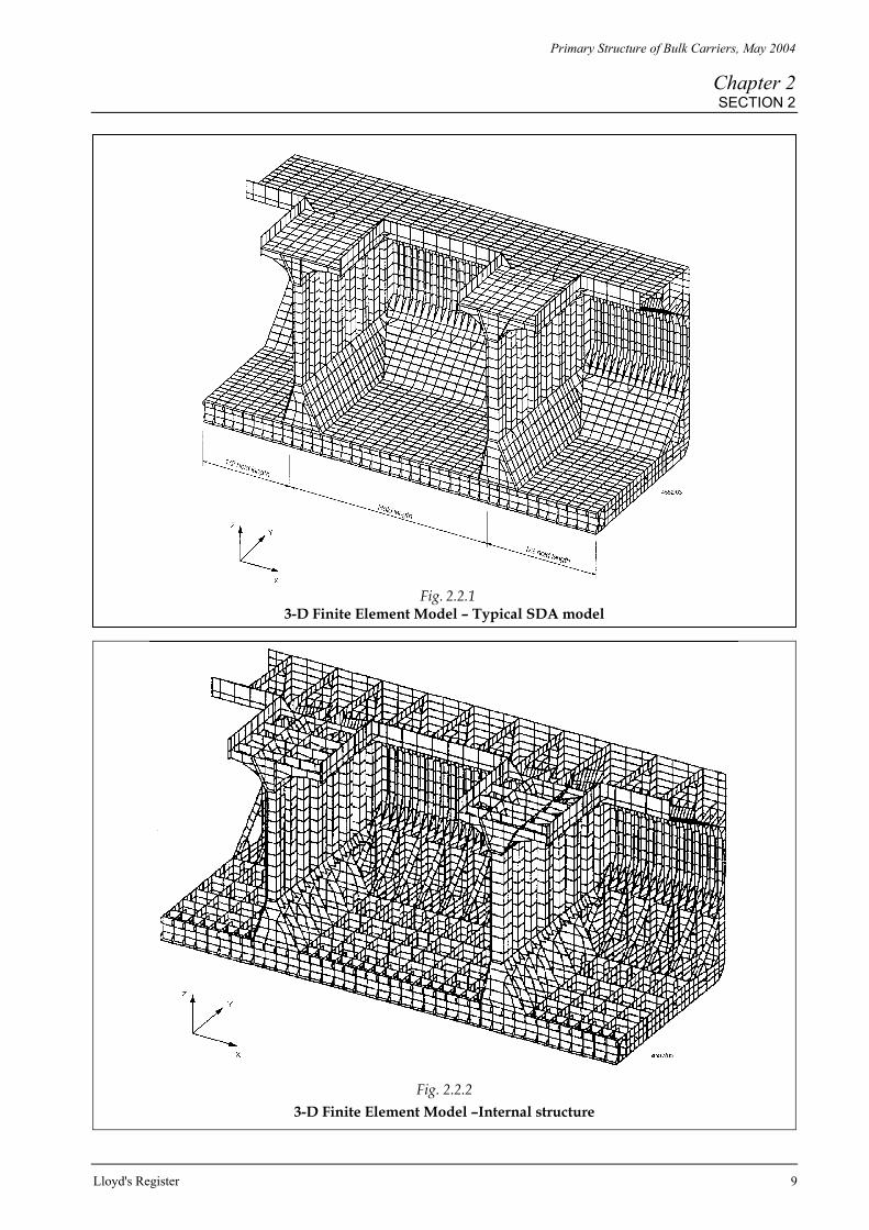
Note: ‘Ore’ cargo hold refers to a hold which is intended to carry heavy cargo, at full load draught, with adjacent holds empty. (iii) Normal/empty cargo hold. 2.3 In general the requirements of 2.2 will be satisfied by using a 3-D finite plate element model of two cargo hold lengths (half + one + half). A typical FE model is shown in Fig. 2.2.1. 2.4 The ends of the two hold length model are to be located at a position midway between the floors supporting the bulkhead stools, see Fig. 2.2.6.

Primary Structure of Bulk Carriers, May 2004
Chapter 2 SECTION 2
6 Lloyd’s Register
2.5 In general only one side of the ship needs to be modelled with appropriate boundary conditions imposed at the centreline. In cases where the ship structure is asymmetrical about the ships centreline, then a full breadth model will be required. The full depth of the ship is to be modelled. The transverse cross-section of the FE model may be prismatic over the model length and the geometry based on the midship section geometry. 2.6 The number of FE models required depend upon the structural arrangements, in particular the transverse bulkhead lower stool arrangements. Where the lower stool arrangements are not symmetrical and/or having different fore and aft extent , three models, in general, are required, i.e. where the ballast hold, ore hold and empty hold is located in the middle of each model. However, consideration will be given to assessment using two models, i.e. one model with the ballast hold in the middle, and the second model with the middle hold used to represent both ore and empty holds. The use of two models is acceptable provided that the ore hold model and empty hold model are very similar in structural arrangements, scantlings, length, etc. 2.7 Notwithstanding paragraph 2.6, where the lower stool arrangements are symmetrical, consideration can be given to assessment using one model, e.g. the fore end half hold of the model is ballast hold, the middle hold is ore hold and the aft end half hold is an empty hold. In such a case the results of the ends hold of the model can also be used for assessment. The appropriate length of the FE model and the number of models required depends on the cargo hold arrangements and is to be agreed with Lloyd’s Register at an early stage. 2.8 The FE model is to be based upon a right handed cartesian co-ordinate system with:
X measured in the longitudinal direction, positive forward. Y measured in the transverse direction, positive to port from the centreline. Z measured in the vertical direction, positive upwards from the baseline.
2.9 The proposed scantlings, excluding Owner’s extras or any additional thickness for the ShipRight ES procedure, are to be used throughout the FE model. 2.10 The selected size and type of plate elements are to provide a satisfactory representation of the deflections and stress distributions within the cargo hold structure. 2.11 In general, the plate element mesh is to follow the stiffening arrangements of the structure. Standard mesh size is to be as follows: • Transversely, one element for every longitudinal stiffener spacing. • Longitudinally, two elements between double bottom floors or one element for every side frame
spacing. • Vertically, one element for every longitudinal stiffener spacing or equivalent. 2.12 Double bottom girders and floors should be defined by three or more plate elements over the depth, see Fig. 2.2.4 and Fig. 2.2.5. 2.13 Transverse ring webs in hopper side tanks and topside tanks should be modelled using at least two elements in the depth. See Fig 2.2.4. 2.14 Side shell hold frames may be defined by plate elements for the web and rod elements for the face plate. 2.15 Corrugated bulkheads should be modelled using one plate element for each flange and web panel of the corrugation. Plate elements are to be defined with membrane and bending properties. Plate elements in the bulkhead near the lower stool and adjacent elements of the stool plating should have an aspect ratio of approximately one. A typical mesh arrangement of a transverse bulkhead is shown in Fig. 2.2.3.

Primary Structure of Bulk Carriers, May 2004
Chapter 2 SECTION 2
Lloyd's Register 7
2.16 Secondary stiffening members are to be modelled using line elements (bars) positioned in the plane of the plating, having axial and bending properties which may be grouped as necessary to suit the mesh arrangement adopted. The bar elements are to have: • A cross-sectional area, representing the stiffener area (or group stiffener area) excluding the area of
attached plating; and • Bending properties, representing the combined effects of the attached plating and stiffener (or
grouped stiffeners). 2.17 The permissible stresses and buckling criteria are based on membrane stress. However, the use of plate elements, with bending properties, may be preferred as this can avoid the problems of low or zero stiffness, for out-of-plane degrees of freedom, associated with pure membrane elements and/or rod elements. 2.18 In general, the use of triangular plate elements is to be kept to a minimum. Where possible, they should be avoided in areas where there are likely to be high stresses or a high stress gradient. Such areas include: • In way of lightening/access holes. • At the connection of corrugated bulkhead, lower stool and shelf plate. • Adjacent to knuckles or structural discontinuities. 2.19 Face plates and plate stiffeners of primary members are to be represented by line elements with the cross sectional area modified, where appropriate, in accordance with Table 2.2.1 and Fig. 2.2.7. Where topside or hopper tank transverse rings are stiffened by a straight parallel face plate on one side of the web, the modelled arrangement is to be an idealized as an opening with a continuous edge stiffener. The effective area of the edge stiffener may be calculated from Table 2.2.1 and Fig. 2.2.2 as a symmetrical curved bracket face bar. 2.20 Where the mesh size of the 3-D FE model is insufficiently detailed to represent areas of localised higher stresses, these areas will generally require to be investigated by means of separate local fine mesh models with boundary conditions derived from the main model. Alternatively, local fine mesh regions may be introduced into the main model. 2.21 For bulk carriers of conventional structural arrangements, i.e. primary structure configuration and spacing as envisaged by the Rules for Ships , only the following high stress areas will normally require to be investigated by fine mesh modelling: • Hopper knuckle. • Transverse bulkhead stool to the double bottom connection at intersection of double bottom girders. If it can be demonstrated by the previous FE investigation or from application of the structural details reflected in the ShipRight Structural Detail Design Guide, that the arrangements proposed are acceptable, then fine mesh models will not be required.
2.22 For bulk carriers with non-conventional structural arrangements, e.g. wide primary structure spacing or where very large openings are incorporated in high stress areas, the scope of fine mesh modelling, in addition to 2.21, will depend on the analysis of results from the main model. In such cases, proposals for additional fine mesh analysis should be agreed with Lloyd’s Register. 2.23 The mesh size in fine mesh regions may be approximately 15t x 15t or 200 mm x 200 mm, whichever is the lesser, where t is the primary member thickness.

Primary Structure of Bulk Carriers, May 2004
Chapter 2 SECTION 2
8 Lloyd’s Register
2.24 Lightening holes, access openings, etc. in primary members may be represented in areas of interest and may be modelled by deleting the appropriate elements. For double bottom girders adjacent to transverse bulkheads and floors adjacent to the hopper knuckle, openings of unusual size, i.e. in excess of the Rule limitation on percentage of web depth (50 per cent of double bottom depth and without edge reinforcement), or of unusual proportion or in close proximity to other openings should be included in the model using a mesh adequate to represent the stress behaviour around such openings. However, no special modelling of openings will be required in respect of openings of standard form, even in close proximity to slots for longitudinals provided that the latter are provided with collar (or filler) plates or equivalent. 2.25 Where lightening holes, access openings, slots for longitudinal without collars, etc., are not represented in the model, the effect of openings are to be taken into account by applying a correction to the resulting shear stresses, see 5.6.
Primary Structure of Bulk Carriers, May 2004
Chapter 2 SECTION 2
Lloyd's Register 9
Fig. 2.2.1
3-D Finite Element Model – Typical SDA model
Fig. 2.2.2
3-D Finite Element Model –Internal structure

Primary Structure of Bulk Carriers, May 2004
Chapter 2 SECTION 2
10 Lloyd’s Register
Fig. 2.2.3
3-D Finite Element Model – Typical transverse bulkhead
Fig. 2.2.4
3-D Finite Element Model – Typical transverse section

Primary Structure of Bulk Carriers, May 2004
Chapter 2 SECTION 2
Lloyd's Register 11
Fig. 2.2.5
3-D Finite Element Model – Typical longitudinal section
Fig. 2.2.6 3-D Finite Element Model – Typical model extent
Primary Structure of Bulk Carriers, May 2004
Chapter 2 SECTION 2
12 Lloyd’s Register
1,0
0,9
0,8
0,7
0,6
0,5
0,4
0,3
0,2
0,1
0,5 1,0 1,5 2,0 2,5 3,0 3,5 4,0
Effective area of face bars = b f tf
0,5b f
Effective Area of Face Bars
R
Effective area of symmetrical face bars
0
tf
Rt f
1,0
0,9
0,8
0,7
0,6
0,5
0,4
0,3
0,2
0,1
0,5 1,0 1,5 2,0 2,5 3,0 3,5 4,0
Effective area of asymmetric face bars
0
Rt f
b f
R
b f
tf
Effective area of face bars = b f tf
b f
moss227
Fig. 2.2.7 Effective area of face bars

Primary Structure of Bulk Carriers, May 2004
Chapter 2 SECTION 2
Lloyd's Register 13
Pe A
rYAA -
+= 2
01
Pe A
2rYAA -
+= 2
01
Table 2.2.1 Line element effective cross-section area
Structure represented Effective area, Ae
Primary member face bars Symmetrical Asymmetrical
Ae = 100% An Ae = 100% An
Curved bracket face bars (continuous)
Symmetrical Asymmetrical From Fig. 2.2.7
Straight bracket face bars (discontinuous)
Symmetrical Asymmetrical
Ae = 100% An Ae = 60% An
Straight portion
Symmetrical Asymmetrical
Ae = 100% An Ae = 60% An Straight bracket face bars
(continuous around toe curvature) Curved
portion Symmetrical Asymmetrical
From Fig. 2.2.7
Flat bars Ae = 25% stiffener area Web stiffeners – sniped both ends Other sections
Flat bars Ae = 75% stiffener area Web stiffeners – sniped one end, connected other end Other sections
Symbols
A = cross-section area of stiffener and associated plating
An = average face bar area over length of line element
Ap = cross-section area of associated plating
I = moment of inertia of stiffener and associated plating
Yo = distance of neutral axis of stiffener and associated plating from median plane of plate r = radius of gyration =
AI

Primary Structure of Bulk Carriers, May 2004
Chapter 2 SECTION 3
14 Lloyd’s Register
■ Section 3: Boundary conditions 3.1 General 3.1.1 This section describes preferred boundary conditions, which are appropriate for investigation of local and global loads that are to be applied to the two cargo hold length as described in 2.3. Alternative boundary conditions may be used but these should be agreed with Lloyd’s Register in advance. 3.1.2 The boundary conditions described in 3.2 and 3.3 are to be combined to enable application of local loads and global loads. 3.1.3 Results derived in the region of the boundary supports will be influenced by the imposed boundary conditions and may not be satisfactorily representative of the actual response of the structure. Therefore, these results may not be suitable for evaluating the structural response. 3.2 Boundary conditions for application of symmetry (see Fig. 2.3.1) 3.2.1 Where a half-breadth FE model is used, symmetry conditions are to be applied to the centreline plane of the FE Model. Therefore each grid point in the centreline plane is to be constrained as follows: • Displacement in the transverse direction is fixed. δy = 0 • Rotation about the longitudinal axis is fixed. θx = 0 • Rotation about the vertical axis is fixed. θz = 0 3.3 Boundary conditions for application of local loads (see Fig. 2.3.1) 3.3.1 For application of local loads, boundary conditions are to be applied to the FE model to represent symmetry at the ends of the model and minimise the hull girder bending induced by the local load distribution. 3.3.2 Symmetry conditions are to be applied to the ends of the model by : Either, restraining appropriate grid points in the end planes as follows: • Displacement in the longitudinal direction is fixed. δx = 0 • Rotation about the transverse axis is fixed. θy = 0 • Rotation about the vertical axis is fixed. θz = 0 Or utilising the rigid plane connectivity at the end plane A as described in. 3.4.3, with the independent grid point D constrained as follows:
δx = θy = θz = 0
In order to prevent singularities, the independent grid point D should also be restrained as follows:
δy = δz = θx = 0 3.3.3 Minimisation of hull girder bending is to be achieved by applying a vertical constraint, i.e. δz = 0, to a grid point in the side shell near the upper deck level at each transverse bulkhead position (Points E). In order to reduce the reaction forces at Points E to near zero, vertical forces are to be applied to a line of grid points at the intersection of each transverse bulkhead with the vertical part of the side shell (Lines C). 3.3.4 Alternatively minimisation of hull girder bending may, be achieved by attaching vertical springs to each of the grid points on Lines C. The overall stiffness k may be calculated as follows:

Primary Structure of Bulk Carriers, May 2004
Chapter 2 SECTION 3
Lloyd's Register 15
k = 65 (G As/Lh)
G = the shear modulus As = the shear area of side shell plating Lh = the cargo hold length
The overall stiffeners k may be distributed to each spring in proportion to the spring spacing in such way that the sum of the each spring stiffness is equal to the overall stiffness. 3.4 Boundary conditions for application of global loads (see Fig. 2.3.1) 3.4.1 For application of global loads, boundary conditions are to be applied to the FE model under application of global loads only in order to produce a uniform hull girder bending moment over the extent of the model. 3.4.2 Symmetry conditions are to be applied to end plane B as given in 3.3.2. The vertical hull bending moment is to be applied at the other end of the FE model (End plane A). 3.4.3 End plane A is to be restrained to remain plane under action of the applied bending moment whilst the cross-section is to be free to deform. To achieve this objective, all relevant grid points in the end plane are to be rigidly linked to a single independent grid point (Grid point D) on the centreline, at approximately the height of the neutral axis, in the following degrees of freedom: • Displacement in the longitudinal direction. δx • Rotation about the transverse axis. θy • Rotation about the vertical axis. θz 3.4.4 The independent grid point is to be constrained as follows: • To prevent rotation of the plane about the vertical axis. θz = 0 • To prevent singularities. δy = δz = θx = 0 3.4.5 To remove rigid body motion, a grid point in the side shell at the end plane A (Point F) should be constrained vertically, i.e. δz = 0. 3.4.6 Applying the hull bending moment, at the independent grid point, will result in application of the hull bending moment to the FE model.

Primary Structure of Bulk Carriers, May 2004
Chapter 2 SECTION 3
16 Lloyd’s Register
(a) Boundary conditions for the application of local loads
Displacement Rotation δ x δy δz θx θ y θz
Centreline plane - Cons - Cons - ConsEnd plane A Cons - - - Cons ConsEnd plane B Cons - - - Cons ConsLine C - - Forces+ - - -Independent grid point D at NA, Plane A Point E - - Cons+ - - -Point F - - - - - -
(b) Boundary conditions for the application of global loads
Displacement Rotation δ x δy δz θx θ y θz
Centreline - Cons - Cons ConsEnd plane A Link - - - Link LinkEnd plane B Cons - - - Cons ConsLine C - - - - - -Independent grid point D at NA, Plane A Point E - - - - - -Point F - - Cons - - -
-
Location
Location
- - - -
BM
-
Cons*Cons* Cons*- Cons*
NOTES
Forces = vertical forces, sec 3.3.3 Cons = constrained (fixed), Link = rigidly linked to independent grid point D BM = bending moment to be applied at this grid point + = alternatively vertical spring see 3.3.4 * = As indicated in see 3.4.4
Fig. 2.3.1
Boundary conditions

Primary Structure of Bulk Carriers, May 2004
Chapter 2 SECTION 4
Lloyd’s Register 17
■ Section 4: Loading conditions 4.1 The load cases which are likely to impose the most onerous local and global load regimes are to be investigated in the structural analysis. This Section includes standard loadcases which are indicated in Table 2.4.2(a-g). The loadcases are based directly on IACS UR S25 and are summarised as follows:
Table No. Description Table 2.4.2(a) Load cases based on homogeneous loading applicable to all notations. Table 2.4.2(b) Load cases of ballast loading applicable to all notations. Table 2.4.2(c) Load cases during loading/unloading in harbour. Table 2.4.2(d) Load cases of loading/unloading in multiple ports based on homogeneous loading applicable to all
notations, except when notation {no MP} is assigned. Table 2.4.2(e) Load cases of alternate ore loading applicable to BC-A notation only. Table 2.4.2(f) Load cases of block ore loading applicable only to BC-A with “any hold may be empty” notation or any
other ” hold … may be empty” notation which allows two adjacent holds loaded with specified holds empty.
Table 2.4.2(g) Load cases of heavy grain loading with slack or empty hold applicable to all notations. See Section 4.3.
4.2 For each project, the loadcases required to be applied in the SDA procedure depend on the proposed class notation of the ship as defined in Pt 4, Ch 7 of the Rules for Ships. Table 2.4.1 provides a guide to the applicable loading conditions for the standard class notations. 4.3 Where specified load cases are agreed between the shipbuilder and the ship owner which are not covered by the load cases given in Tables 2.4.2(a-g) then these may be considered as additional or optional load cases. For example, the slack loading of grain cargo as illustrated in Table 2.4.2(g) is not a standard condition and is not covered by hold mass curves drawn from standard loading conditions. 4.4 Full details of all the proposed design load cases are to be submitted to Lloyd’s Register at an early stage for agreement of the required SDA loadcases. 4.5 Cargo loads are to be applied to the cargo hold boundaries using the method described in Section 7. 4.6 Fuel oil tanks and/or other tanks in the double bottom in way of cargo holds are to be included in the model.

Primary Structure of Bulk Carriers, May 2004
Chapter 2 SECTION 4
18 Lloyd’s Register
Table 2.4.1 Loading conditions application table
Y Applicable.
Y1 May be dispensed with since the loading conditions are satisfactorily covered by other loading condition.
O Applicable, only if proposed as a design base or in Loading Manual. See Section 4.3. N Not applicable. 4.7 Loads arising from liquids such as ballast/fuel oil are to be applied to the space boundaries as equivalent pressure loads as on all contacted surfaces: • For completely filled spaces, the pressure head is normally to be measured to the top of the tank top,
or the top of the hatch coaming as appropriate. • For the hopper side tank and/or double bottom tank, which are not connected to the topside tank, the
pressure head is to be measured to the top of the tank or half distance to the top of the overflow, whichever is greater.
• Where ballast water exchange at sea utilising flow through method is agreed between the owner and builder as a design basis, the pressure head is to be equivalent to the full distance to the top of the overflow.
URS25 paragraph
Load case Table No. Applicable hold BC-A BC-A (no MP)
BC-B & BC-C
BC-B (no MP) & BC-C (no MP)
5.2.1 Homo 1 2.4.2(a) Any hold Y1 Y1 Y1 Y 5.2.2 Homo 2 2.4.2(a) Any hold Y Y Y Y 5.3.1 Mp 1 2.4.2(d-1) Any hold Y N Y N 5.3.2 Mp 2 2.4.2(d-1) Any hold Y N Y N 5.3.3 Mp 3 2.4.2(d-1) Any two adjacent
holds Y N Y N
5.3.3 Mp 3B 2.4.2(d-2) Any two adjacent holds including ballast hold
Y N Y N
5.3.4 Mp 4 2.4.2(d-2) Any two adjacent holds
Y N Y N
5.4.2 Alt. 1H 2.4.2(e – 1) Ore hold Y Y N N 5.4.2 Alt. 1S 2.4.2(e – 1) Ore hold Y Y N N 5.4.1 Alt. 2H 2.4.2(e – 2) Empty hold Y Y N N
Alt. 3 2.4.2(e – 2) Ore hold Y Y N N 5.4.3 Blk. 1H 2.4.2(f) Two adjacent
intended holds O O N N
5.4.3 Blk. 1S 2.4.2(f) Two adjacent intended holds
O O N N
5.2.3 Bal. 1 2.4.2(b – 1) Any hold Y Y Y Y 5.5.1 Bal. 2 2.4.2(b – 1) Ballast hold Y Y Y Y 5.5.1 Bal. 3 2.4.2(b – 2) Ballast hold Y Y Y Y 5.5.1 Bal. 4 2.4.2(b – 2) Ballast hold Y Y Y Y 5.6.1 Har. 1 2.4.2(c) Any hold Y1 Y Y1 Y 5.6.2 Har. 2 2.4.2(c) Ant two adjacent
holds Y1 Y Y1 Y
5.6.1 Har. 3 2.4.2(c) Ore hold. Y Y N N Slk.1 2.4.2(g) Intended hold O O O O

Primary Structure of Bulk Carriers, May 2004
Chapter 2 SECTION 4
Lloyd’s Register 19
4.8 External pressure is to be applied to the hull surface of the model as two separate load components: • The static component is the hydrostatic pressure due to immersion of the hull to a specified draught.
The draught to be used depends on the load case as specified in Tables 2.4.2(a-g). • The wave component is the additional or reduced pressure due to the presence of a wave crest or
trough. The magnitude and distribution of the pressure on the hull surface is to be based on the method shown in Fig. 2.4.1 and is to be constant for the full longitudinal extent of the model. The wave component is to be applied to the load cases as specified in Tables 2.4.2(a-g).
4.9 Hull girder bending loads are to be simulated by applying a suitable bending moment to the model as a separate load case, using boundary conditions as described in Section 3. If desired, alternative procedures, including the simple beam theory, may be adopted for the purpose of determining the hull bending stress. In this case, the method of combining the hull bending and local stresses should be agreed with Lloyd’s Register. 4.10 Where Tables 2.4.2(a-g) indicate that the still water bending moment is to be based on the actual value, the magnitude of still water bending moment is to be derived using a conventional longitudinal strength/still water loads analysis, from a loading condition based on the SDA load case. 4.11 A small longitudinal bending stress will be generated in the FE model due to local pressure load distribution. If desired, the bending moment applied to the model for the global load case may be modified by a small amount to take account of this. The magnitude of the applied hull bending moment may be determined in accordance with the following steps:
Step Procedure 1 Calculate the still water bending moment value Ma, at the mid-hold length of the middle hold
using a still water loads analysis of the loading condition, corresponding to the load case under consideration.
2 Calculate the Rule wave bending moment value Mw at the same location. 3 Calculate the hull bending moment, ∆ Ma, at the mid-hold length of the middle hold, due to
local loading, by the simple beam theory, using net loads in the holds and the boundary conditions similar to that given in 3.3
4 Calculate the corrected total hull bending moment value, Mt Mt = Ma * - ∆ Ma + Mw where Ma * is the lesser of 1,05 Ma or Ms Ms is the permissible still water bending moment
5 Apply Mt to the model using the boundary conditions given in 3.4

Primary Structure of Bulk Carriers, May 2004
Chapter 2 SECTION 4
20 Lloyd’s Register
Alternative methods are to be agreed with Lloyd’s Register.
(a) Wave crest Wc = ρ (Hw + h) for - Hw ≤ h < 0 Wc = ρ Hw {1 – (1 – kz) h/T} for 0 ≤ h
(b) Wave trough
Wt = - ρ h {1 – (1 – kz) Hw /T} for 0 ≤ h < Hw Wt = - ρ Hw {1 – (1 – kz) h/T} for Hw ≤ h
Where Hw = 0,046 L e-0.0044L m for L < 227 m Hw = 3,846 m for L ≥ 227 m L = Rule ship length, in metres T = draught, in metres in the loading condition being analysed h = distance, in metres, below the still waterline kz = e-d d = 2 π T/L ρ = density of sea water
Fig. 2.4.1
Wave pressure distribution on hull surface

Primary Structure of Bulk Carriers, May 2004
Chapter 2 SECTION 4
Lloyd’s Register 21
Table 2.4.2(a) Load cases based on homogeneous loading applicable to all notations
Local loads Global loads Load case Loads in hold and double
bottom External pressure
Hull bending Illustration of load case
Homo. 1 (5.2.1)*
(a) Any hold carries Mfull and other holds carry Mfull
(b) Fuel oil tanks in double bottom if any fully filled.
(c) Ballast water tanks in double bottom empty
(a) Scantling draught
(b) Wave trough
Tsc – Wt
(a) Permissible still water bending moment (sagging)
(b) Sagging Rule wave bending moment
-Mss – Mws
Homo. 2 (5.2.2)*
(a) Any hold carries 0,5Mh and other holds carry Mh
(b) All double bottom tanks empty
(a) Scantling draught
(b) Wave crest
Tsc + Wc
(a) Permissible still water bending moment (hogging)
(b) Hogging Rule wave bending moment
Msh + Mwh
* IACS UR S25 Para.
Mfull
Fuel
Mfull Mfull
-Mss - Mws-Mss - Mws
S.G. = Min. 1.0(BC-C)
S.G. = 3.0(BC-A/BC-B)
Fuel
T sc -
Wt
T sc +
Wc
Msh + MwhMsh + Mwh
0.5 Mh
Mh Mh
Primary Structure of Bulk Carriers, May 2004
Chapter 2 SECTION 4
22 Lloyd’s Register
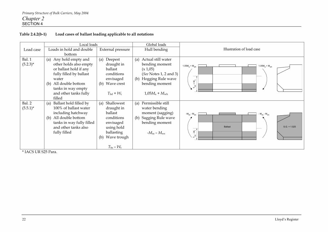
Table 2.4.2(b-1) Load cases of ballast loading applicable to all notations
Local loads Global loads Load case Loads in hold and double
bottom External pressure Hull bending
Illustration of load case
Bal. 1 (5.2.3)*
(a) Any hold empty and other holds also empty or ballast hold if any fully filled by ballast water
(b) All double bottom tanks in way empty and other tanks fully filled
(a) Deepest draught in ballast conditions envisaged
(b) Wave crest
Tbd + Wc
(a) Actual still water bending moment (x 1,05) (See Notes 1, 2 and 3)
(b) Hogging Rule wave bending moment
1,05Ma + Mwh
Bal. 2 (5.5.1)*
(a) Ballast hold filled by 100% of ballast water including hatchway
(b) All double bottom tanks in way fully filled and other tanks also fully filled
(a) Shallowest draught in ballast conditions envisaged using hold ballasting
(b) Wave trough
Tbs – Wt
(a) Permissible still water bending moment (sagging)
(b) Sagging Rule wave bending moment
-Mss – Mws
* IACS UR S25 Para.
T bd +
Wc
1.05Ma + Mwh 1.05Ma + Mwh
Ballast
T bs -
Wt
- Mss - Mws-Mss - Mws
S.G. = 1.025

Primary Structure of Bulk Carriers, May 2004
Chapter 2 SECTION 4
Lloyd’s Register 23
Table 2.4.2(b-2) Load cases of ballast loading applicable to all notations
Local loads Global loads Load case Loads in hold and double
bottom External pressure Hull bending
Illustration of load case
Bal. 3 (5.5.1)* Assessment of hopper tank transverse ring web adjacent to ballast hold
(a) Ballast hold filled by 100% of ballast water including hatchway
(b) Topside, hopper and double bottom tanks in way empty and other tanks also empty
(a) Shallowest draught in ballast conditions envisaged using hold ballasting
Tbs
(a) Ballast hold filled by 100% of ballast water including hatchway
(b) Topside, hopper and double bottom tanks in way empty and other tanks also empty
(c) Equivalent additional head ∆h on ballast hold boundaries due to roll motion
(a) Draught
D/3 + ∆h
Ballast water head, in metres, is calculated on ballast hold boundaries as follows: H = h + ∆h
Bal. 4 (5.5.1)* Assessment of topside tank transverse ring web adjacent to ballast hold only
where h = vertical head measured from top of coaming, in metres. ∆h = equivalent additional head, in metres, ∆h = b sinθ + ht (cosθ - 1) b = horizontal distance, in metres, from coaming side to the mid-breadth of topside tank sloped bulkhead on the opposite side. ht = vertical distance, in metres, from top of coaming to the mid-breadth of topside tank sloped bulkhead. θ = roll angle, in degrees, θ = 0, sin-1 {(0,5 + 0, L/B) (0,4 – L/1270)}
* IACS UR S25 Para.
Ballast
T bs
S.G. = 1.025
Ballast S.G. = 1.025
D/3
+ ∆
h
Primary Structure of Bulk Carriers, May 2004
Chapter 2 SECTION 4
24 Lloyd’s Register
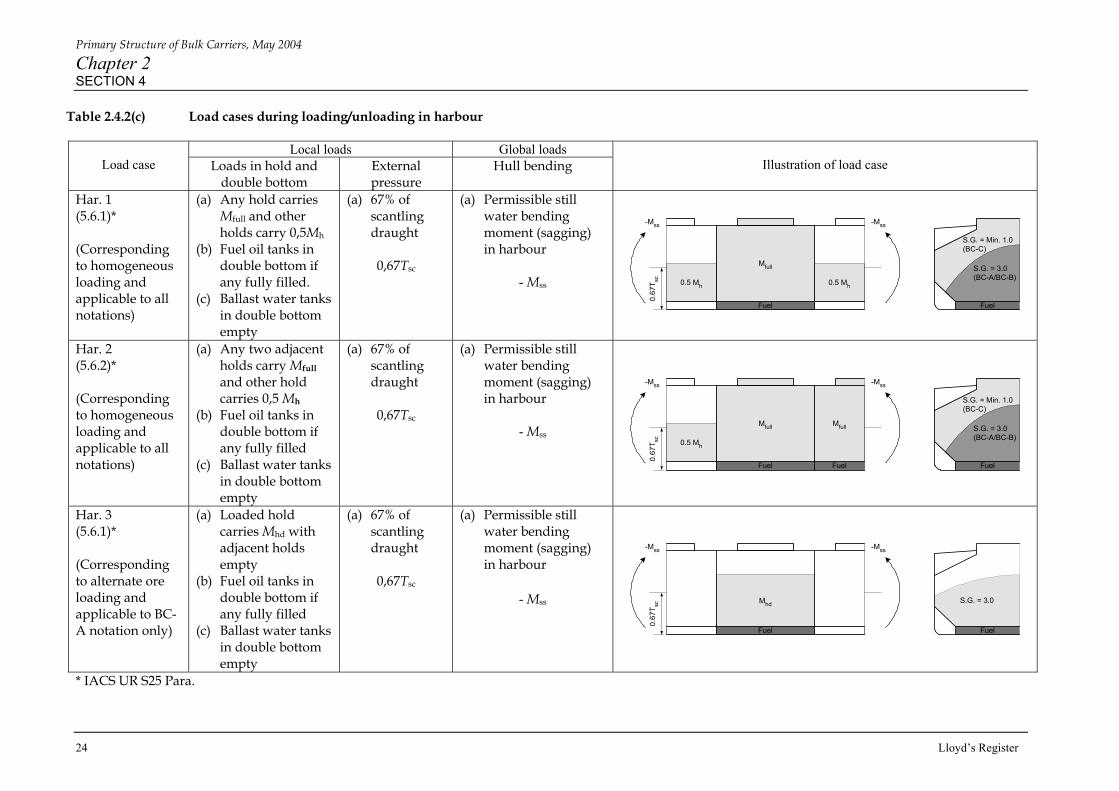
Table 2.4.2(c) Load cases during loading/unloading in harbour
Local loads Global loads Load case Loads in hold and
double bottom External pressure
Hull bending
Illustration of load case
Har. 1 (5.6.1)* (Corresponding to homogeneous loading and applicable to all notations)
(a) Any hold carries Mfull and other holds carry 0,5Mh
(b) Fuel oil tanks in double bottom if any fully filled.
(c) Ballast water tanks in double bottom empty
(a) 67% of scantling draught
0,67Tsc
(a) Permissible still water bending moment (sagging) in harbour
- Mss
Har. 2 (5.6.2)* (Corresponding to homogeneous loading and applicable to all notations)
(a) Any two adjacent holds carry Mfull and other hold carries 0,5 Mh
(b) Fuel oil tanks in double bottom if any fully filled
(c) Ballast water tanks in double bottom empty
(a) 67% of scantling draught
0,67Tsc
(a) Permissible still water bending moment (sagging) in harbour
- Mss
Har. 3 (5.6.1)* (Corresponding to alternate ore loading and applicable to BC-A notation only)
(a) Loaded hold carries Mhd with adjacent holds empty
(b) Fuel oil tanks in double bottom if any fully filled
(c) Ballast water tanks in double bottom empty
(a) 67% of scantling draught
0,67Tsc
(a) Permissible still water bending moment (sagging) in harbour
- Mss
* IACS UR S25 Para.
Mfull
Fuel
0.5 Mh 0.5 Mh
0.67
T sc
-Mss-Mss
S.G. = Min. 1.0(BC-C)
S.G. = 3.0(BC-A/BC-B)
Fuel
Mfull
FuelFuel
0.5 Mh
Mfull
0.67
T sc
-Mss-Mss
S.G. = Min. 1.0(BC-C)
S.G. = 3.0(BC-A/BC-B)
Fuel
Mhd
Fuel
0.67
T sc
-Mss-Mss
S.G. = 3.0
Fuel

Primary Structure of Bulk Carriers, May 2004
Chapter 2 SECTION 4
Lloyd’s Register 25
Table 2.4.2(d-1) Load cases of loading/unloading in multiple ports based on homogeneous loading applicable to all notations except when notation (no MP) is assigned
Local loads Global loads Load case Loads in hold and double
bottom External pressure
Hull bending
Illustration of load case
Mp. 1 (5.3.1)*
(a) Any hold carries Mfull and other holds empty
(b) Fuel oil tanks in double bottom if any fully filled.
(c) Ballast water tanks in double bottom empty
(a) 67% of scantling draught
(b) Wave trough
0,67Tsc - Wt
(a) Permissible still water bending moment (sagging)
(b) Sagging Rule wave bending moment
- Mss – Mws
Mp. 2 (5.3.2)*
(a) Any hold is empty and other holds carry Mh
(b) All double bottom tanks empty
(a) 83% of scantling draught
(b) Wave crest
0,83Tsc + Wc
(a) Permissible still water bending moment (hogging)
(b) Hogging Rule wave bending moment
Msh + Mwh
Mp. 3 (5.3.3)* Assessment of cross deck and T. Bhd structures
(a) Any two adjacent holds carry Mfull and other hold empty
(b) Fuel oil tanks in double bottom if any fully filled
(c) Ballast water tanks in double bottom empty
(a) 67% of scantling draught
(b) wave trough
0,67Tsc – Wt
(a) Permissible still water bending moment (sagging)
(b) Sagging Rule wave bending moment
- Mss – Mws
* IACS UR S25 Para.
Mfull
Fuel
-Mss - Mws-Mss - Mws
S.G. = Min. 1.0(BC-C)
S.G. = 3.0(BC-A/BC-B)
Fuel0.67
T sc -
Wt
Mh Mh
Msh + MwhMsh + Mwh
0.83
T sc +
Wc
Mfull
FuelFuel
Mfull
-Mss - Mws-Mss - Mws
S.G. = Min. 1.0(BC-C)
S.G. = 3.0(BC-A/BC-B)
Fuel0.67
T sc -
Wt

Primary Structure of Bulk Carriers, May 2004
Chapter 2 SECTION 4
26 Lloyd’s Register
Table 2.4.2(d-2) Load cases of loading/unloading in multiple ports based on homogeneous loading applicable to all notations except when notation (no MP) is assigned
Local loads Global loads Load case Loads in hold and double
bottom External pressure
Hull bending
Illustration of load case
Mp. 3B (5.3.3)* Assessment of cross deck and T. Bhd structures
(a) Any two adjacent holds including ballast hold, Ballast hold 100% filled to top of coaming, adjacent hold Mfull, other hold empty
(b) Fuel oil tanks in double bottom if any fully filled
(c) Ballast water tanks in double bottom empty
(a) 67% of scantling draught
(b) wave trough
0,67Tsc – Wt
(c) Permissible still water bending moment (sagging)
(d) Sagging Rule wave bending moment
- Mss – Mws
Mp. 4 (5.3.4)* Assessment of cross deck and T. Bhd structures
(a) Any two adjacent holds empty and other hold carries Mh
(b) All double bottom tanks empty
(a) 75% of scantling draught
(b) Wave crest
0,75Tsc + Wc
(a) Permissible still water bending moment (hogging)
(b) Hogging Rule wave bending moment
Msh + Mwh
* IACS UR S25 Para.
Ballast
FuelFuel
Mfull
-Mss - Mws-Mss - Mws
Ballast
Fuel0.67
T sc -
Wt
Mh
Msh + MwhMsh + Mwh
0.75
T sc +
Wc

Primary Structure of Bulk Carriers, May 2004
Chapter 2 SECTION 4
Lloyd’s Register 27
Table 2.4.2(e - 1) Load cases of alternate ore loading applicable to BC-A notation only
Local loads Global loads Load case Loads in hold and
double bottom External pressure
Hull bending
Illustration of load case
Alt. 1H (5.4.2)* (Hold partially filled by heavy ore)
(a) Loaded hold carries Mhd + 0,1 Mh with adjacent holds empty
(b) Fuel oil tanks in double bottom if any fully filled.
(c) Ballast water tanks in double bottom empty
(a) Scantling draught
(b) Wave crest
Tsc + Wc
(a) Actual still water bending moment (x 1,05) (See Notes 1, 2 and 3)
(b) Hogging Rule wave bending moment
1,05Ma + Mwh
Alt. 1S (5.4.2)* (Hold partially filled by heavy ore)
(a) Loaded hold carries Mhd + 0,1 Mh with adjacent holds empty
(b) Fuel oil tanks in double bottom if any fully filled.
(c) Ballast water tanks in double bottom empty
(a) Scantling draught
(b) Wave trough
Tsc – Wt
(a) Actual still water bending moment (x 1,05) (See Notes 1, 2 and 3)
(b) Sagging Rule wave bending moment
1,05Ma – Mws
* IACS UR S25 Para.
Mhd + 0.1 Mh
Fuel
T sc +
Wc
1.05Ma + Mwh1.05Ma + Mwh
S.G. = 3.0
Fuel
Mhd + 0.1 Mh
Fuel
T sc -
Wt
1.05Ma - Mws1.05Ma - Mws
S.G. = 3.0
Fuel

Primary Structure of Bulk Carriers, May 2004
Chapter 2 SECTION 4
28 Lloyd’s Register
Table 2.4.2(e-2) Load cases of alternate ore loading applicable to BC-A notation only
Local loads Global loads Load case Loads in hold and double
bottom External pressure
Hull bending
Illustration of load case
Alt. 2H (5.4.1)* (Holds partially filled by heavy ore)
(a) Empty hold with adjacent holds carrying Mhd
(b) All double bottom tanks empty
(a) Scantling draught
(b) Wave crest
Tsc + Wc
(a) Actual still water bending moment (x 1,05) (See Notes 1, 2 and 3)
(b) Hogging Rule wave bending moment
1,05Ma + Mwh
Alt. 3 Assessment of W. T. Bhd and hopper tank trans. ring web (Hold filled to top of hatch coaming by light ore)
(a) Loaded hold carries Mhd + 0,1 Mh with adjacent holds empty
(b) All double bottom tanks empty
(a) Scantling draught
(b) Wave trough
Tsc – Wt
* IACS UR S25 Para.
T sc +
Wc
1.05Ma + Mwh1.05Ma + Mwh
Mhd Mhd
Mhd + 0.1 Mh
T sc -
Wt
Primary Structure of Bulk Carriers, May 2004
Chapter 2 SECTION 4
Lloyd’s Register 29
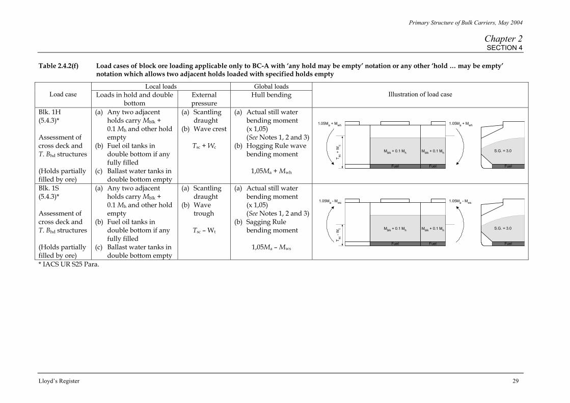
Table 2.4.2(f) Load cases of block ore loading applicable only to BC-A with ‘any hold may be empty’ notation or any other ‘hold … may be empty’ notation which allows two adjacent holds loaded with specified holds empty
Local loads Global loads Load case Loads in hold and double
bottom External pressure
Hull bending
Illustration of load case
Blk. 1H (5.4.3)* Assessment of cross deck and T. Bhd structures (Holds partially filled by ore)
(a) Any two adjacent holds carry Mblk + 0.1 Mh and other hold empty
(b) Fuel oil tanks in double bottom if any fully filled
(c) Ballast water tanks in double bottom empty
(a) Scantling draught
(b) Wave crest
Tsc + Wc
(a) Actual still water bending moment (x 1,05) (See Notes 1, 2 and 3)
(b) Hogging Rule wave bending moment
1,05Ma + Mwh
Blk. 1S (5.4.3)* Assessment of cross deck and T. Bhd structures (Holds partially filled by ore)
(a) Any two adjacent holds carry Mblk + 0.1 Mh and other hold empty
(b) Fuel oil tanks in double bottom if any fully filled
(c) Ballast water tanks in double bottom empty
(a) Scantling draught
(b) Wave trough
Tsc – Wt
(a) Actual still water bending moment (x 1,05) (See Notes 1, 2 and 3)
(b) Sagging Rule bending moment
1,05Ma – Mws
* IACS UR S25 Para.
Mblk + 0.1 Mh
FuelFuel
T sc +
Wc
1.05Ma + Mwh1.05Ma + Mwh
S.G. = 3.0
Fuel
Mblk + 0.1 Mh
Mblk + 0.1 Mh
FuelFuel
T sc -
Wt
1.05Ma - Mws1.05Ma - Mws
S.G. = 3.0
Fuel
Mblk + 0.1 Mh
Primary Structure of Bulk Carriers, May 2004
Chapter 2 SECTION 4
30 Lloyd’s Register
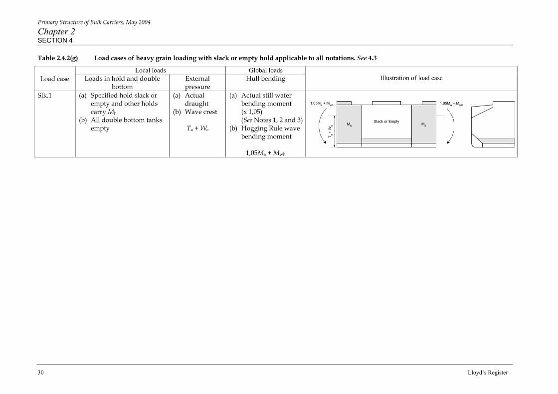
Table 2.4.2(g) Load cases of heavy grain loading with slack or empty hold applicable to all notations. See 4.3
Local loads Global loads Load case Loads in hold and double
bottom External pressure
Hull bending
Illustration of load case
Slk.1 (a) Specified hold slack or empty and other holds carry Mh
(b) All double bottom tanks empty
(a) Actual draught
(b) Wave crest
Ta + Wc
(a) Actual still water bending moment (x 1,05) (See Notes 1, 2 and 3)
(b) Hogging Rule wave bending moment
1,05Ma + Mwh
T a +
Wc
1.05Ma + Mwh1.05Ma + Mwh
Mh MhSlack or Empty

Primary Structure of Bulk Carriers, May 2004
Chapter 2 SECTION 4
Lloyd’s Register 31
Table 2.4.2(h) Symbols/definitions and notes for load cases
Symbols and definitions L = B = D = Tsc = Ta = Tbd = Tbs =
Rule ship length, in metres ship breadth, in metres ship depth, in metres scantling draught, in metres actual draught, in metres deepest draught, in metres, in relevant ballast conditions envisaged shallowest draught, in metres, in relevant ballast conditions envisaged using hold ballasting but excluding ballast water exchange conditions
Wc = Wt = Ma = Msh = Mss = Mwh = Mws =
wave pressure distribution on hull surface in wave crest wave pressure distribution on hull surface in wave trough actual still water bending moment relevant to each load case hogging maximum permissible still water bending moment sagging maximum permissible still water bending moment hogging Rule wave bending moment sagging Rule wave bending moment Mh, Mfull, Mhd and Mblk as defined in Chapter 1, Section 2 ‘Symbols’
NOTES 1. 2. 3.
Ma is the actual still water bending moment calculated under the basic loading condition relevant to the load case and envisaged in the trim and stability calculation booklet. Ma is to be taken as the maximum still water bending moment, hogging or sagging as appropriate, which may be calculated in the vicinity of the mid-hold length of the middle hold of the FE model. 1,05Ma is not to exceed the maximum permissible still water bending moment.

Primary Structure of Bulk Carriers, May 2004
Chapter 2 SECTION 5
32 Lloyd’s Register
■ Section 5: Stress acceptance criteria 5.1 The stresses resulting from application, of the load cases specified in Tables 2.4.2(a-g), are, in general, not to exceed the maximum permissible values given in Table 2.5.1(a) with associated symbols and definitions shown in Table 2.5.1(b). The assessment of the scantlings of each structural item is to be based on the most severe criteria. 5.2 The permissible stresses in Table 2.5.1(a) are based on the mesh size recommended in Section 2. Different permissible stresses apply in course mesh and fine mesh regions. Attention is drawn to the relationship between the magnitude of calculated stress and the mesh size in areas where there is likely to be high stress and high stress gradient. A high stress due to meshing techniques, e.g. incorporation of smaller elements and/or triangular elements, or in isolated locations due to boundary condition etc, may be specially considered. 5.3 Permissible stresses in Table 2.5.1(a) are defined for separate local and combined load cases. 5.4 The structural items listed in Table 2.5.1(a), are provided for guidance as to the most likely critical areas. All parts of the model are to be examined for high values of stress. 5.5 The hull girder stresses are to be combined with the local stresses in order to check compliance with the permissible ‘combined stress’. When the global stress results are not based on application of the procedure of described in 4.10, the ‘combined stress’ may be reduced by a small amount to reflect the ‘built-in’ hull bending stress resulting from the application of local loads. 5.6 The mean shear stress, τ , is to be taken as the average shear stress over the depth of the web of the primary member and is to be compared with the criteria in Table 2.5.1(a). Where openings are not represented in the model, the mean shear stress τ results from the model are to be increased in direct proportion to the intact shear area divided by the net shear area. The calculation of the net shear area is to take account of the actual structural configuration. Common structural arrangements of double bottom construction with corresponding method to calculate the net shear area are shown in Table 2.5.1(c). The revised τ is to be used to calculate the Von Mises equivalent stress σe in the element. The resulting stresses are not to be greater than the permissible values given in Table 2.5.1(a). 5.7 For bulkheads, the stresses at the ends of the corrugation are to be obtained by extrapolation of the mean stresses within the bulkhead plating. 5.8 For large bulk carriers, with narrow deck strips or where it is the intention to fully load any two adjoining holds with adjacent holds empty for a sea-going condition, or for bulk carriers to be classed ‘any hold may be empty’, the cross deck scantlings will need to be assessed with the ‘Strength of bulk carrier deck strips’ software program (ShipRight program No. 20107) or equivalent. See Pt 4, Ch 7,4 of the Rules for Ships.

Primary Structure of Bulk Carriers, May 2004
Chapter 2 SECTION 5
Lloyd’s Register 33
Table 2.5.1(a) Maximum permissible stresses (See Table 2.5.1(b) for notes)
Permissible stresses (N/mm2) Structural items Load cases Applied stresses σ τ σe
Upper deck outside line of openings and topside tank sloping bulkhead (See Note 5)
All load cases except for Alt.3, Bal.3 and Bal.4
Combined stress (See Note 1)
0,92σo — —
Combined stress (See Note 1) 0,92σo — σo Bottom shell, inner bottom and hopper side tank sloping bulkhead
All load cases except for Alt.3, Bal.3 and Bal.4 Local stress (in longitudinal)
(in transverse) 0,63σo 0,63σo
— 0,75σo
Combined stress (See Note 1) — — σo Double bottom girders All load cases except for Alt.3, Bal.3 and Bal.4 Local stress — 0,42σo 0,75σo
Double bottom floors All load cases except for Alt.3, Bal.3 and Bal.4
Local stress — 0,42σo 0,75σo
Hopper side tank transverse ring web
All load cases except for Bal.4 Local stress 0,75σo Local stress
0,42σo 0,75σo
Hopper side tank transverse ring web and bulkhead in way of hold transverse bulkhead
All load cases except for Bal.4, Mp.3, Mp.3B, Mp.4, Blk.1H, Blk.1S and Har. 2
Local stress 0,75σo (See Note 2)
0,42σo 0,75σo
Mp.3, Mp.3B, Mp.4, Blk.1H, Blk.1S and Har. 2
Local stress (See Note 3)
0,85σo
(See Note 2) 0,47σo
0,85σo
Topside tank transverse ring web.
All load cases except for Alt.3, Bal.3
Local stress 0,75σo (See Note 2)
0,42σo 0,75σo
Topside tank transverse ring web and bulkhead in way of hold transverse bulkhead
All load cases except for Alt.3, Bal.3, Mp.3, Mp.3B, Mp.4, Blk.1H, Blk.1S and Har. 2
Local stress 0,75σo (See Note 2)
0,42σo 0,75σo
Mp.3, Mp.3B, Mp.4, Blk.1H, Blk.1S and Har. 2
Local stress (See Note 3)
0,85σo
(See Note 2) 0,47σo
0,85σo
All load cases except for Mp.3, Mp.3B, Mp.4, Alt.3, Blk.1H, Blk.1S, Bal.1, Bal.4 and Har. 2
Local stress (corrugation) (others)
0,63σo
0,63σo 0,35σo 0,42σo
0,75σo
0,75σo Deep tank transverse bulkheads, upper and lower stools
Mp.3, Mp.3B, Mp.4, Blk.1H, Blk.1S and Har. 2
Local stress (See Note 3)
0,7σo 0,47σo
0,85σo

Primary Structure of Bulk Carriers, May 2004
Chapter 2 SECTION 5
34 Lloyd’s Register
All load cases except for Mp.3, Mp.3B, Mp.4, Blk.1H, Blk.1S, Bal.2, Bal.3, Bal.4 and Har. 2
Local stress 0,63σo 0,35σo
(corrugation) 0,42σo(others)
0,75σo Watertight transverse bulkheads, upper and lower stools
Mp.3, Mp.3B, Mp.4, Blk.1H, Blk.1S and Har. 2
Local stress (See Note 3)
0,7σo 0,47σo
0,85σo
All load cases except for, Bal.3, Bal.4 ,Mp.3, Mp.3B, Mp.4, Blk.1H, Blk.1S and Har. 2
Local stress 0,63σo
(deck plate) 0,75σo
(See Note 2)
0,42σo 0,75σo Cross deck
Mp.3, Mp.3B, Mp.4, Blk.1H, Blk.1S and Har. 2
Local stress (See Note 3)
0,63σo
(deck plate) 0,85σo
(See Note 2)
0,47σo
0,85σo
Average stress (See Note 4) — — σo Fine mesh regions (See 2.20 and 2.23)
All load cases except for Bal.4 Peak stress — — 1,2σo
Table 2.5.1(a) (Continued) Table 2.5.1(b) Symbols/definitions and notes for maximum permissible stresses
Symbols and definitions NOTES σ = τ = σe = = σL = σo =
direct stress mean shear stress Von Mises equivalent stress (σx2 + σy2 - σx σy + 3τxy2) 0.5 σx = direct stress in the element x direction σy = direct stress in the element y direction τxy = shear stress in the element xy plane 235/kL kL = higher tensile steel factor, see Pt 3, Ch 2,1.2 of the Rules for Ships. Specified minimum yield stress. Special consideration will be given to the steel of σo ≥ 355 N/mm2
1. 2. 3. 4. 5.
Hull bending stress component is to be combined with longitudinal component of local stresses. Only applicable to the stress in the face plate of the transverse and/or girder web. Based on a standard two cargo hold lengths model (half + one + half) constrained by the boundary conditions for local loads described in 3.3. Where a longer length FE model is used for two adjacent holds loading conditions, the stress criteria will be specially considered. The average of the stresses in the elements around and including the element being assessed for the peak stress. Details of hatch side coaming end brackets should comply with those shown in ‘Structural Detail Design Guide’ and are outside the scope of SDA analysis.
Primary Structure of Bulk Carriers, May 2004
Chapter 2 SECTION 5
Lloyd’s Register 35
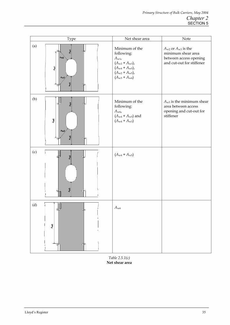
Type Net shear area Note
(a) Minimum of the following: Aw1, (Aw2 + Aw3), (Aw4 + Aw5), (Aw2 + Aw5), (Aw3 + Aw4)
Aw2 or Aw3 is the minimum shear area between access opening and cut-out for stiffener
(b) Minimum of the following: Aw6, (Aw4 + Aw5) and (Aw4 + Aw3)
Aw3 is the minimum shear area between access opening and cut-out for stiffener
(c) (Aw4 + Aw5)
(d) Aw6
Table 2.5.1(c) Net shear area
Primary Structure of Bulk Carriers, May 2004
Chapter 2 SECTION 6
36 Lloyd’s Register
■ Section 6: Buckling acceptance criteria 6.1 Plate panel buckling is to be investigated for all areas of the primary structures, but particular attention should be paid to the following areas: • Double bottom floors, especially at mid-hold length. • Double bottom girders, especially at ends of holds adjacent to bulkheads or stools, at first plate opening
from bulkheads or stool, at mid-hold. • Bottom shell and inner bottom plating, especially at ends of holds adjacent to bulkheads or stools, at mid-hold. • Hopper side tank transverse ring web. • Hopper sloped plate. • Topside tank transverse ring web in way of ballast hold. • Transverse bulkhead and ring structures in topside and hopper side tank in way of the hold transverse
bulkhead. • Topside tank sloped plate in way of the transverse bulkhead. • Bulkhead and stool plating, especially at mid-span of bulkhead and adjacent to stool, in stool shelf plate
outboard. • Cross deck plate and upper stool. 6.2 Transversely framed top side tank lower part is currently outside the scope of a buckling assessment. 6.3 The combined interaction of bi-axial compressive stresses, shear stresses and ‘in-plane’ bending stresses are to be taken into consideration in the panel bucking calculation. In general, the average stresses acting within the plate panel are to be used for the buckling calculation. 6.4 The applied load cases to be assessed for buckling are indicated in Section 4 and Table 2.6.2(a) with associated symbols and definitions shown in Table 2.6.2(b). The derived factors against buckling for the specified primary structural items are to be not less than the required factors against buckling, λ, given in Table 2.6.2(a). 6.5 The calculated equivalent buckling stress is to be based on a ‘corroded thickness’ of plating, tcorr calculated as follows :
tcorr = t – tc
Where t is the modelled thickness tc is the standard thickness deduction as defined in Table 2.6.1.
Table 2.6.1 Standard thickness deduction for corrosion
Position Standard thickness Deduction, in mm
One side exposure to water ballast 1,0 Water ballast tanks within 1,5 m of weather deck Two sides exposed to water ballast 2,0 Elsewhere 1,0

Primary Structure of Bulk Carriers, May 2004
Chapter 2 SECTION 6
Lloyd’s Register 37
6.6 For the analysis of the buckling requirements based on local loads, the equivalent applied stress is to be calculated by increasing the stress result from the FE model in proportion to the modelled thickness of the plating divided by the corroded thickness:
σa = σLOCAL x t tcorr
Where σa is equivalent applied stress σLOCAL is stress from the FE model
6.7 For the analysis of the buckling requirements based on combined local and global loads, the equivalent applied stress is to be calculated by adding the local stress corrected in accordance with 6.6 to the global stress result:
σa = σLOCAL x t + σGLOBAL tcorr
Where σGLOBAL is the stress resulting from the application of the hull girder bending moment. 6.8 The panel edge restraint factor ‘c’, as defined in Pt 3, Ch 4,7 of the Rules for Ships, may be taken into account in the calculation of the critical elastic buckling stress of panels subjected to compressive loading on the long edge of the panel. A mean ‘c’ value may be used for a panel, one edge of which is restrained by a plated structure such as girder and the other edge by a stiffener. For a double bottom floor panel, the longer edge of which is restrained by stiffeners which are connected to face plate of bottom and inner bottom longitudinal, the ‘c’ value may be taken as 1.15. No edge restraint factor is to be taken into account for compressive loading on the short edge. 6.9 When the critical equivalent elastic buckling stress exceeds 50 per cent of the specified minimum yield stress, then the buckling stress is to be adjusted for the effects of plasticity using the Johnson – Ostenfeld formula (given below):
σcr = σo (1 – σo/4σc)
where σcr is the critical equivalent buckling stress corrected for plasticity effects σc is the critical equivalent elastic buckling stress σo is the specified minimum yield stress
6.10 The panel buckling calculation is to be carried out using the software ‘LR ShipRight SDA buckling module’ or ‘Buckling of flat rectangular plate panels’ (ShipRight program No. 10403)’, or equivalent. ShipRight IS performs the foregoing calculations and requires no external correction by the user.
Primary Structure of Bulk Carriers, May 2004
Chapter 2 SECTION 6
38 Lloyd’s Register
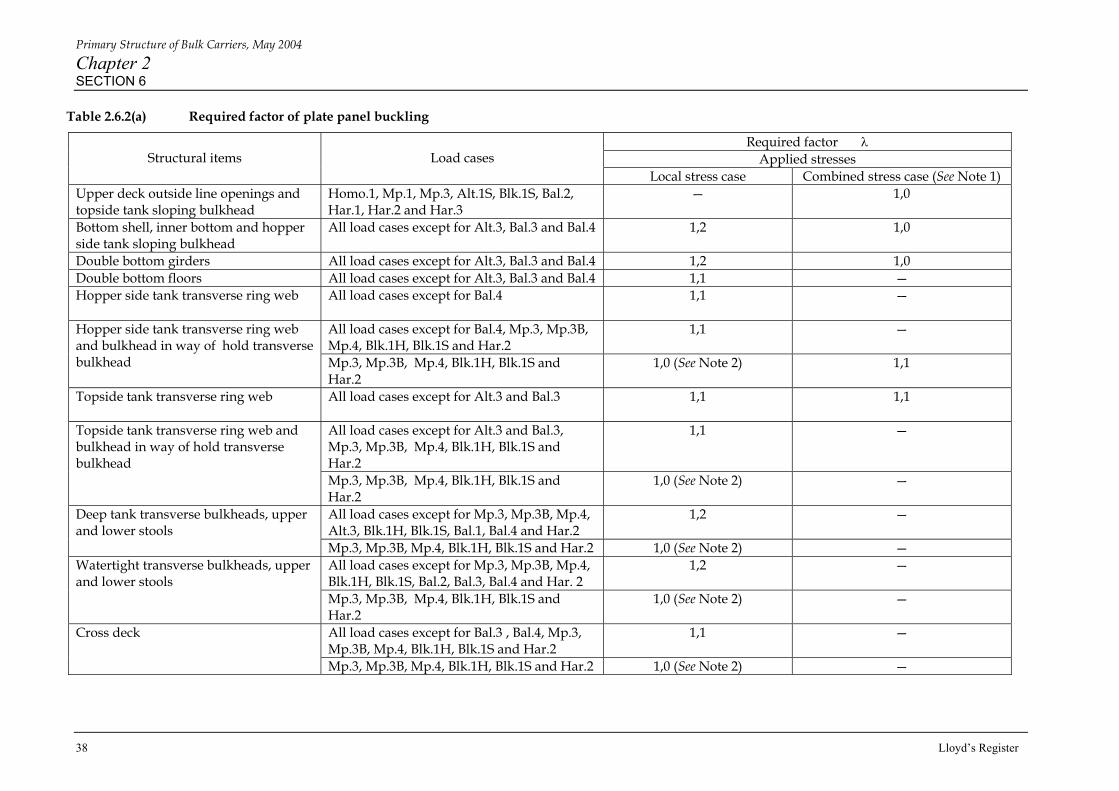
Table 2.6.2(a) Required factor of plate panel buckling
Required factor λ Applied stresses
Structural items
Load cases
Local stress case Combined stress case (See Note 1) Upper deck outside line openings and topside tank sloping bulkhead
Homo.1, Mp.1, Mp.3, Alt.1S, Blk.1S, Bal.2, Har.1, Har.2 and Har.3
— 1,0
Bottom shell, inner bottom and hopper side tank sloping bulkhead
All load cases except for Alt.3, Bal.3 and Bal.4 1,2 1,0
Double bottom girders All load cases except for Alt.3, Bal.3 and Bal.4 1,2 1,0 Double bottom floors All load cases except for Alt.3, Bal.3 and Bal.4 1,1 — Hopper side tank transverse ring web
All load cases except for Bal.4 1,1 —
All load cases except for Bal.4, Mp.3, Mp.3B, Mp.4, Blk.1H, Blk.1S and Har.2
1,1 — Hopper side tank transverse ring web and bulkhead in way of hold transverse bulkhead
Mp.3, Mp.3B, Mp.4, Blk.1H, Blk.1S and Har.2
1,0 (See Note 2) 1,1
Topside tank transverse ring web
All load cases except for Alt.3 and Bal.3 1,1 1,1
All load cases except for Alt.3 and Bal.3, Mp.3, Mp.3B, Mp.4, Blk.1H, Blk.1S and Har.2
1,1 — Topside tank transverse ring web and bulkhead in way of hold transverse bulkhead
Mp.3, Mp.3B, Mp.4, Blk.1H, Blk.1S and Har.2
1,0 (See Note 2) —
All load cases except for Mp.3, Mp.3B, Mp.4, Alt.3, Blk.1H, Blk.1S, Bal.1, Bal.4 and Har.2
1,2 — Deep tank transverse bulkheads, upper and lower stools
Mp.3, Mp.3B, Mp.4, Blk.1H, Blk.1S and Har.2 1,0 (See Note 2) — All load cases except for Mp.3, Mp.3B, Mp.4, Blk.1H, Blk.1S, Bal.2, Bal.3, Bal.4 and Har. 2
1,2 — Watertight transverse bulkheads, upper and lower stools
Mp.3, Mp.3B, Mp.4, Blk.1H, Blk.1S and Har.2
1,0 (See Note 2) —
All load cases except for Bal.3 , Bal.4, Mp.3, Mp.3B, Mp.4, Blk.1H, Blk.1S and Har.2
1,1 — Cross deck
Mp.3, Mp.3B, Mp.4, Blk.1H, Blk.1S and Har.2 1,0 (See Note 2) —

Primary Structure of Bulk Carriers, May 2004
Chapter 2 SECTION 6
Lloyd’s Register 39
Table 2.6.2(b) Symbols/definitions and notes for required factor of plate panel buckling
Symbols and definitions NOTES λ = =
Required factor of safety of plate panel buckling σcr/σa
σa = equivalent applied stress σcr = critical equivalent buckling stress
σcr = σc for σc ≤ 0,5σo σcr = σo (1 – σo/4σc) for σc > 0,5σo
σc = critical equivalent elastic buckling stress σo = specified minimum yield stress
1. 2
Hull bending stress component is to be combined with the longitudinal component of local stresses. For structural items below the neutral axis, compressive stresses arising from hogging hull bending moments are to be taken into account in buckling calculation. For structural items above the neutral axis, compressive stresses arising from sagging hull bending moments are to be taken into account. Based on a standard two cargo hold lengths model (half + one + half) constrained by the boundary conditions for local loads described in 3.3. Where a longer length FE is used for two adjacent holds loading conditions, the required safety of buckling will be specially considered.

Primary Structure of Bulk Carriers, May 2004
Chapter 2 SECTION 7
40 Lloyd’s Register
-2
45tan2 ψ
■ Section 7: Cargo loads 7.1 Due to the material properties of ore and the manner in which ore cargoes are loaded, there is no definitive shape to the ore cargo surface within a hold. 7.2 For the purpose of the SDA procedure, heavy ore cargo is to be represented by pressure loads determined on the basis of a parabolic cargo surface, as shown in Fig. 2.7.1, in association with a cargo density of 3,0 tonnes/m3. The transverse parabolic surface is to be maintained constant in the longitudinal direction. The angle of intersection of the cargo surface with the side shell plating is to be taken as the angle of repose. 7.3 The ore cargo pressure load, ρc, is to be calculated as follows:
ρc = f ρc hc
where f = 1,0 for all horizontal and sloping bulkhead surfaces
=
for all vertical surfaces
ψ = angle of repose in degrees
ρc = the density of ore cargo
hc = the local height of ore cargo
7.4 The angle of repose is to be taken as 35° for heavy ore or light ore cargo, grain cargo, etc. 7.5 For light grain or coal cargo fully filling a hold, the pressure loads are to be based on a level cargo surface at the top of the hatch coaming. The applicable cargo density is to be calculated on the basis of the maximum allowable cargo mass and the volume of the hold to the top of the coaming. 7.6 In cases where the cargo hold is full, ore cargo is assumed to apply no load on surfaces above the cargo, i.e. topside sloping bulkhead, upper stool sloping wall and underside of cross deck. 7.7 Slack loading of grain cargoes may be assumed to have a level cargo surface

Primary Structure of Bulk Carriers, May 2004
Chapter 2 SECTION 7
Lloyd’s Register 41
-2
121Byh
4B tan (35°)
32 1
hLBh
7.8 The local height of heavy ore cargo is calculated for the parabolic surface as follows (see Fig. 2.7.1): hc = hy + h2
where hy = local height of the parabolic surface =
h1 = local height of the surface at the
centre line =
≈ 0,175B
h2 = height of the surface at the side shell being estimated against the corresponding volume V2 using the hold volume curve
V2 = V - V1 V = ore cargo volume =
V1 = the cargo volume above h2. =
≈ 0,117B2 Lh
Mc = ore cargo mass in hold B = the ship breadth, as defined in 1.2.1 Lh = the hold length y = the ordinate measured in the transverse direction from the centre line
Fig. 2.7.1
Parabolic cargo surface for heavy ore cargo
ρC
CM
Primary Structure of Bulk Carriers, May 2004
Chapter 2 SECTION 8
42 Lloyd’s Register
■ Section 8: Hold mass curves 8.1 The Rules for Ships require hold mass curves to be included in the loading manual and the loading instrument and cover use of any single hold and any two adjacent holds at sea and during loading and unloading operations in harbour. The curves show the maximum allowable and minimum required cargo mass as a function of draught. 8.2 The hold mass curves are to be developed on the basis of the results of the load cases investigated in the SDA Procedure. In this respect, ballast water in a hold should be excluded from the hold mass curve. 8.3 At other draughts, than those specified in Tables 2.4.2(a) to (g), the maximum allowable and the minimum required mass are to be derived by adjusting the cargo mass for the change in buoyancy acting on the bottom. The change in buoyancy is to be calculated using the waterplane area corresponding to each particular draught. 8.4 During loading and unloading in harbour, the maximum allowable mass in a cargo hold may be 15 per cent greater than the maximum mass allowed in a seagoing condition, but shall not exceed the mass allowed at the scantling draught in seagoing condition. The minimum required mass in harbour may be reduced by the same amount. 8.5 For guidance, Figs. 2.8.1(a) and (b) and Figs. 2.8.2(a) and (b) show the hold mass curves for any single hold and two adjacent holds based on specified ship’s notation.

Primary Structure of Bulk Carriers, May 2004
Chapter 2 SECTION 8
Lloyd’s Register 43
Fig. 2.8.1(a)
Hold mass curves for any single hold applicable to ‘BC-C, no MP’ and ‘BC-B, no MP’
Fig. 2.8.1(b)
Hold mass curves for any single hold applicable to ‘BC-C’ and ‘BC-B’ (with MP)
Mmax1 = Mfull (Homo.1) Mmin1 = 0,5Mh (Homo.2) Mfull and Mh as defined in Ch 1,2 ‘Symbols’
Mmax1 = Mfull (Homo.1) Mmin1 = 0,5Mh (Homo.2) Mfull and Mh as defined in Ch 1,2 ‘Symbols’
Primary Structure of Bulk Carriers, May 2004
Chapter 2 SECTION 8
44 Lloyd’s Register
(i) Empty hold
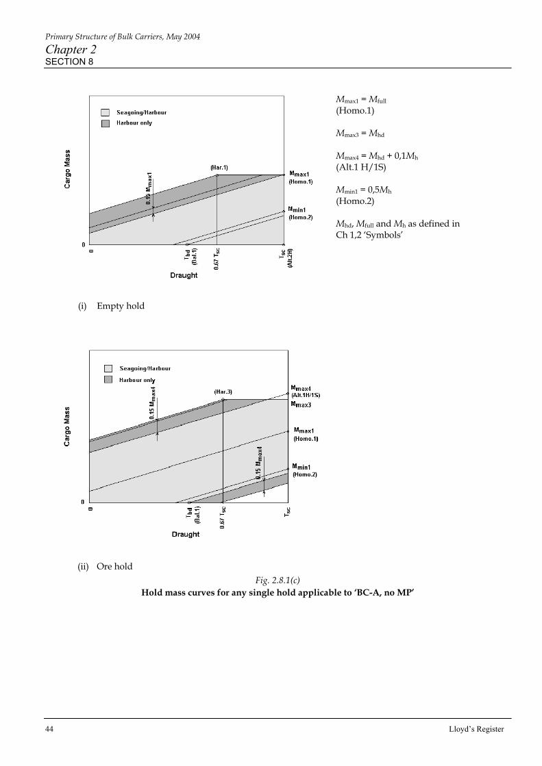
(ii) Ore hold Fig. 2.8.1(c)
Hold mass curves for any single hold applicable to ‘BC-A, no MP’
Mmax1 = Mfull (Homo.1) Mmax3 = Mhd Mmax4 = Mhd + 0,1Mh (Alt.1 H/1S) Mmin1 = 0,5Mh (Homo.2) Mhd, Mfull and Mh as defined in Ch 1,2 ‘Symbols’

Primary Structure of Bulk Carriers, May 2004
Chapter 2 SECTION 8
Lloyd’s Register 45
(i) Empty hold
(ii) Ore hold
Fig. 2.8.1(d) Hold mass curves for any single hold applicable to ‘BC-A’ (with MP)
Mmax1 = Mfull (Homo.1) Mmax3 = Mhd Mmax4 = Mhd + 0,1Mh (Alt.1 H/1S) Mmin1 = 0,5Mh (Homo.2) Mhd, Mfull and Mh as defined in Ch 1,2 ‘Symbols’

Primary Structure of Bulk Carriers, May 2004
Chapter 2 SECTION 8
46 Lloyd’s Register
Fig. 2.8.2(a)
Hold mass curves for any two adjacent holds applicable to all notations (no MP)
Fig. 2.8.2(b)
Hold mass curves for any two adjacent holds applicable to all notations (with MP)
Mmax1 = ∑(Mfull) (Homo.1) Mmax4 = Mhd + 0,1Mh (Alt.1H/1S) Mhd, Mfull and Mh as defined in Ch 1,2 ‘Symbols’ ∑ means the sum of mass in fore and aft holds.
Mmax1 = ∑(Mfull) (Homo.1) Mmax4 = Mhd + 0,1Mh (Alt.1H/1S) Mhd, Mfull and Mh as defined in Ch 1,2 ‘Symbols’ ∑ means the sum of mass in fore and aft holds.

Primary Structure of Bulk Carriers, May 2004
Chapter 2 SECTION 8
Lloyd’s Register 47
Fig. 2.8.2(c) Hold mass curves for two adjacent holds block ore loading with ‘BC-A, no MP’ notation
Fig. 2.8.2(d) Hold mass curves for two adjacent holds block ore loading with ‘BC-A’ notation (with MP)
Mmax1 = ∑(Mfull) (Homo.1) Mmax4 = Mhd + 0,1Mh (Alt.1 H/1S) Mmax5 = ∑(Mblk) Mmax6 = ∑(Mblk + 0,1Mh) (Blk.1 H/1S) Mblk, Mhd, Mfull and Mh as defined in Ch 1,2 ‘Symbols’ ∑ means the sum of mass in fore and aft holds
Mmax1 = ∑(Mfull) (Homo.1) Mmax4 = Mhd + 0,1Mh (Alt.1 H/1S) Mmax5 = ∑(Mblk) Mmax6 = ∑(Mblk + 0,1Mh) (Blk.1 H/1S) Mblk, Mhd, Mfull and Mh as defined in Ch 1,2 ‘Symbols’ ∑ means the sum of mass in fore and aft holds