scroll liquid chillers - trane liquid chillers 20 to 60 tons (60 hz) ... — advanced design —...
TRANSCRIPT
Scroll Liquid Chillers
20 to 60 Tons (60 Hz)
17 to 50 Tons (50 Hz)
Water-Cooled and Condenserless
CG-PRC011-ENJanuary 2002
Built For the Industrial and Commercial Markets

CG-PRC011-EN© 2002 American Standard Inc. All rights reserved.
Features andBenefits
More Than Just Another “Improved”Chiller— Advanced Design— Better Reliability— Superior Efficiency— Smarter Microprocessor Control— Better Availability— Easier To Install and Operate
The Trane 20-60 Ton Scroll Liquid Chiller
Evaporator LeavingWater Piping
DesignThe Trane scroll compressor is the mostadvanced compressor in the industry.
Reliability64 percent fewer compressor parts,compared to reciprocating compressors,mean long and reliable life.
EfficiencyCGWE scroll chillers meet and exceedASHRAE Standard 90.1 full and part loadefficiencies. Part load efficiencies aresimply unmatched by reciprocatingchillers.
ControlAdvanced and complete safety andcontrol algorithms available.
AvailabilityFast ship cycles on both stock and built-to-order specials.
InstallationSmall unit size, factory wiring, easylifting provisions, and start-up controllogic mean quick and easy setup.Chillers fit through standard single-width door.
OperationSmart safety features and over 40diagnostic displays mean easy andvirtually trouble-free operation.
Power Supply Monitor ProtectsCompressors From Phase Loss, PhaseReversal, Phase Imbalance, Incorrect PhaseSequence and Under and Over Voltage
Rugged TraneScrollCompressor
ControlPanel
MicroprocessorOperatorInterface
CondenserLeavingWater Piping
CondenserEnteringWater Piping
3CG-PRC011-EN
Contents
Features and Benefits
Model Number Description
General Data
Application Considerations
Selection Procedure
Performance Adjustment Factors
Performance Data
Electrical Data
Jobsite Connection
Controls
Dimensional Data
Weights
Options
Typical Wiring Diagrams
Features Summary
Mechanical Specifications
2
9
10
11
12
13
15
24
26
28
29
34
35
36
38
39
CG-PRC011-EN4
Standard Features
Microprocessor ControlMicroprocessor control means the scrollchiller maintains chilled watertemperature more accurately, resulting inless temperature drift in the building. Themicroprocessor control also incorporatesoptimal chiller start-up logic (low andhigh ambient), load limiting, compressoranti-recycle timing, auto lead/lagfunction, compressor protection, andmany other safety features. The “smart”safety features provide complete faultprotection without nuisance tripping.
BENEFIT: consistent, reliable operation,longer life.
Leaving Chilled WaterTemperature ControlThe microprocessor actually monitorstemperature and the rate of change overtime, effectively controlling compressorloading for efficient chiller operation.
BENEFIT: accurate and efficient buildingcomfort, less energy wasted.
Diagnostics and DisplayThe microprocessor’s operator interfaceis a menu-driven digital display. Thedisplay provides temperatures,pressures, setpoints and diagnosticsreadouts. Flashing display notifiesoperator of fault condition anddiagnostics are saved until manuallyreset.
BENEFIT: easy troubleshooting andcontrol
Compressor ProtectionAll compressors are individuallyprotected against starting and runningoverload, under and over voltages,phase loss, phase reversal, high windingtemperature and rapid recycling.
BENEFIT: long unit life and addedreliability.
External ControlSeveral external contacts are providedfor custom control requirementsincluding time of day scheduling and kWdemand limiting.
BENEFIT: more standard control andmore flexible owner upgrades.
Other Standard Features• Control power transformer• Auto lead/lag (on or off)• Solid-state motor protection• Insulation (Armaflex II or equal)• Evaporator and condenser water pumpinterlocks
• Filter-dryer• Built-in loss of chilled water flowsensors
• Chillers fit through standard singlewidth door.
The standard ARI rating condition(54/44°F and 85°F/3.0 gpm per ton) andIPLV are ARI certified. All other ratings,including the following, are outside thescope of the certification program andare excluded:• Glycol.• 50 Hz.• Condenserless models CCAD.
Options• Trane Integrated Comfort™ systems
communication• Generic building automation systems
(BAS) interface• Chilled water reset (ambient, zone,
return)• Ice making• Hot gas bypass• Remote display/control panel• Remote running indication and alarm
contact• Unit-mounted disconnect• Gauges• Sound Attenuation• Neoprene Isolators• Compressor cycle counter/hour meter• Water regulating valves• Condenser water temperature sensors
Water Chiller Systems Business Unit
Features andBenefits

5CG-PRC011-EN
Leading in Efficiency and Reliability with State-Of-The-ArtScroll Compressor Technology
EfficiencyThe energy efficiency of the scroll chillerresults in energy costs lower than anyother comparable chiller. Full loadefficiencies are improved beyondreciprocating chillers, but part loadefficiencies are simply unmatched by anyother manufacturer.
Superior efficiencies are obtained bycombining many of the traditional scrollchiller energy efficient features with theTrane scroll compressor technology.HERE’S HOW:
• Scroll compressor’s positivedisplacement design
• Dual refrigerant circuits (40-60 ton units)• Multiple compressors• Optimum system design• Reduced friction• No valves• Advanced heat transfer surfaces
Chart illustrates low torque variation of theTrane scroll compressor vs reciprocatingcompressor.
Graph illustrates Trane scroll chiller’s superior annual energy costs vs typical reciprocatingchillers.
Features andBenefits
Operating Torque
ReliabilityThe Trane scroll chiller with many newimprovements, now brings an excitingnew compressor to the commercialmarket — the Trane scroll compressor.Trane has designed the scrollcompressor to be a leader in reliability.HERE’S HOW:
• Simple design with 64 percent fewerparts than equal capacity reciprocatingcompressor.
• Scroll compliance allows liquid and dirtto pass through without damagingcompressor (liquid slugging resistant).
• Advanced microelectronics protect bothcompressor and motor from typicalelectrical fault conditions.
• Scroll compressors have less than athird the torque variations of areciprocating compressor.
• Years of laboratory testing haveoptimized compressor and chillersystems reliability.
• Water-cooled scroll chillers are factorytested.
ASHRAE Standard 90.1 All Tranechillers meet and exceed the newefficiency levels mandated by ASHRAEStandard 90.1. This new standardrequires higher efficiencies than pasttechnologies can deliver. In fact, energyefficiency is so paramount the USFederal Government has adoptedstandard 90.1. Federal Executive Ordermandates energy consuming devicesprocured must be in the top 25% of theirclass. In the case of chillers, ASHRAE90.1 is the product standard formeasurement.
Risk. Not only has ASHRAE 90.1 beenadopted by the US Federal Government,it’s expected to be adopted domestically,if not globally, in the future. Make surethat your chillers as well as your entireHVAC system complies, or you may becaught retrofitting your project with newequipment and paying extra designdollars if the code changes duringconstruction.
Trane’s CGWE was designed with theend user’s requirements in mind.Efficiency and reliability were primarydesign concerns with this latestgeneration machine.
Scroll Chiller Energy Usage Savings
Kilo
wat
t Hou
rs
Chiller Load (%)
Typical ReciprocatingChiller
Scroll Chiller
10-20% Annual Energy Savings

CG-PRC011-EN6
Trane Scroll Compressor— Maximum Efficiency with Enhanced Reliability
GeneralThe scroll compressor has two scrolls.The top scroll is fixed and the bottomscroll orbits. Each scroll has walls in aspiral shape that intermesh.
Inlet-First OrbitAs the bottom scroll orbits, tworefrigerant gas pockets are formed andenclosed.
Compression-Second OrbitThe refrigerant gas is compressed as thevolume is reduced closer to the center ofthe scroll.
Discharge-Third OrbitThe gas is compressed further anddischarged through a small port in thecenter of the fixed scroll.
Scroll Principal ComponentsThis is a cutaway view of a hermetic,scroll compressor, showing the relativepositions of the principal components.Shown is a Trane 10-ton, 3600 rpm, 60 Hz[3000 rpm, 50 Hz] scroll compressor asan example.
The principle of operation of thisexample compressor is as follows: Thesuction gas is drawn into the compressorat A. The gas then passes through thegap between the rotor and stator, B,cooling the motor, before it enters thecompressor housing, C. Here, thevelocity of the gas is reduced, causing aseparation of the entrained oil from thegas stream. The gas then enters theintake chamber, D, that encircles thescrolls.
Finally, the suction gas is drawn into thescroll assembly where it is compressedand discharged into the dome of thecompressor. The dome of this examplecompressor acts as a hot gas mufflerwhich dampens the pulsations before thegas enters the discharge line, E.
Features andBenefits
7CG-PRC011-EN
Packed Stock For Fast DeliveryWhen your project is a fast-track job,Trane can help. A wide range of chillersare stocked and can be shipped soonafter receipt of your order.
Build To OrderNeed a special chiller fast? Think Tranescroll chillers. New manufacturingtechnology and inventory control meansthe fastest delivery schedule in theindustry. Wide array of standard optionsprovides the right chiller for the job fast.
Installation• Only one power connection hook-up —for fast and inexpensive installation.
• Integrated Comfort™ system meansonly single pair connections arerequired for control interfaces andtherefore, lower total installation costs.
• Factory refrigerant and oil chargedunits help speed installation.
• All units easily fit through a standardsingle width door.
• Built-in chilled water flow sensorsmean no field-installed flow switchesare required.
• Microprocessor displays both enteringand leaving chilled water temperatures.No chilled water thermometers arerequired.
Easy ServiceabilityTrane 20 through 60 ton scroll chillersare designed with service personnel inmind. All major components arereplaceable without complete unitdisassembly. Plus, the microprocessorcontrol panel provides diagnosticcapability to aid service personnel inanalyzing problems. Therefore, if aproblem does occur, the chiller can be upand running in a shorter period of time.
Quick and Complete SubmittalsThe Trane commitment to value-addedproducts doesn’t stop at just theproducts, we are committed to totalcustomer satisfaction. Part of thiscommitment is to provide quick,complete, readable and accuratedrawings.
Trane Value Means Fast Availability,Easy Installation and Quality Service
Single-Source ResponsibilityA wide range of products designed forcomplete compatibility are available withthe scroll chillers. Your entire buildingcomfort system can be completed usingcomponents from Trane.
The Added Value of ApplicationsExpertiseWith the scroll chiller you getapplications expertise and know-howfrom a Trane sales engineer. Trane hasmore than 1500 sales engineers acrossthe country — each one a degreedengineer. Trane sales engineers havecreative ideas and solutions to difficultbuilding comfort system designproblems. You can take full advantage oftheir knowledge in designing a quality,dependable comfort system.
There’s more. Your Trane sales engineeris backed by the Trane worldheadquarters staff of applicationsexperts, regarded as the best in theindustry. The C.D.S. Network providesTrane sales engineers — and manyindependent design and consulting firms— direct access to many comfort systemapplication, selection and designprograms.
You get a quality chiller, properlyselected and applied in a properlydesigned system. That means a comfortsystem that works, the first time!
Features andBenefits
CG-PRC011-EN8
Trane Integrated ComfortSystemThe Future Is Now!
Simple• Factory packaging for smooth start-up.• Easy to install with only a single twistedwire pair to the central Tracer buildingmanagement system.
• Constant, comprehensive monitoringtracks equipment operation and takescontrol to keep tenants comfortable.
• Optional override buttons on each floorallow tenants to have control afterhours. After-hours use is automaticallylogged to allow tenant billing.
• Review building performance at aglance with automatically generatedreports and logs.
• Enhanced service and buildingmanagement capability through remotediagnostics and control.
• Trane Building Management Networkallows control from across town oracross the country.
A Dependable System From A Single,Reliable Source• System design, equipment supply andservice support all available from Trane.
• Factory testing of all Trane equipmentensures the system works.
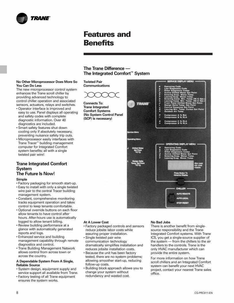
The Trane Difference —The Integrated Comfort™ System
No Other Microprocessor Does More SoYou Can Do LessThe new microprocessor control systemenhances the Trane scroll chiller byproviding advanced technology tocontrol chiller operation and associatedsensors, actuators, relays and switches.• Operator interface is improved andeasy to use. Panel displays all operatingand safety codes with completediagnostic information. Over 40diagnostics are included.
• Smart safety features shut downcooling only if absolutely necessary,preventing nuisance safety trip outs.
• Microprocessor easily interfaces withTrane Tracer™ building managementcomputer for Integrated Comfortsystem benefits; all with a singletwisted pair wire!
Twisted PairCommunications
Connects To:Trane IntegratedComfort Systems(No System Control Panel(SCP) is necessary)
At A Lower Cost• Factory packaged controls and sensorsreduce jobsite labor costs whileassuring proper installation.
• Single twisted pair wirecommunication technologydramatically simplifies installation andreduces jobsite installation costs.
• Because the unit has been factorytested, there are no system problems;allowing smoother start-up, reducingfollow-up costs.
• Building block approach allows you tochange your system withoutredundancy and wasted cost.
No Bad JobsThere is another benefit from single-source responsibility and the TraneIntegrated Comfort systems. With TraneICS, you get a single-source supplier ofthe system — from the chillers to the airhandlers to the controls. Trane is theonly HVAC manufacturer which canprovide the entire system.
For more information on how Tranescroll chillers and an Integrated Comfortsystem can benefit your next HVACproject, contact your nearest Trane salesoffice.
Features andBenefits
9CG-PRC011-EN
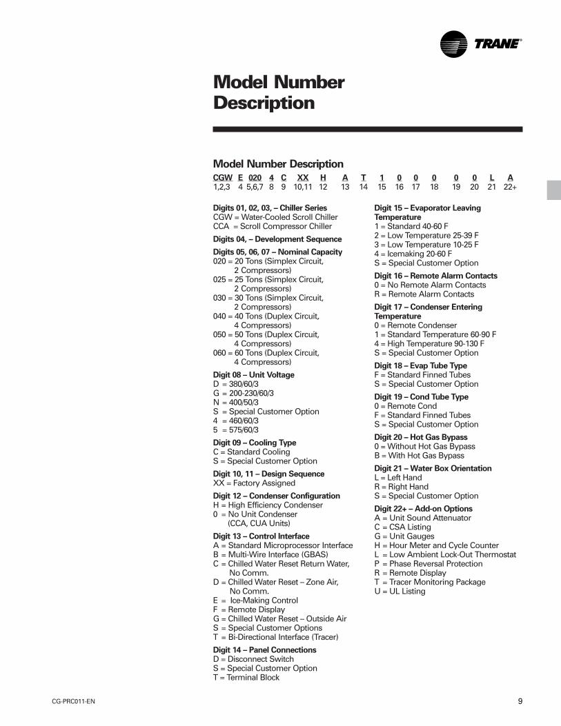
Model NumberDescription
Digits 01, 02, 03, – Chiller SeriesCGW = Water-Cooled Scroll ChillerCCA = Scroll Compressor Chiller
Digits 04, – Development Sequence
Digits 05, 06, 07 – Nominal Capacity020 = 20 Tons (Simplex Circuit,
2 Compressors)025 = 25 Tons (Simplex Circuit,
2 Compressors)030 = 30 Tons (Simplex Circuit,
2 Compressors)040 = 40 Tons (Duplex Circuit,
4 Compressors)050 = 50 Tons (Duplex Circuit,
4 Compressors)060 = 60 Tons (Duplex Circuit,
4 Compressors)
Digit 08 – Unit VoltageD = 380/60/3G = 200-230/60/3N = 400/50/3S = Special Customer Option4 = 460/60/35 = 575/60/3
Digit 09 – Cooling TypeC = Standard CoolingS = Special Customer Option
Digit 10, 11 – Design SequenceXX = Factory Assigned
Digit 12 – Condenser ConfigurationH = High Efficiency Condenser0 = No Unit Condenser
(CCA, CUA Units)
Digit 13 – Control InterfaceA = Standard Microprocessor InterfaceB = Multi-Wire Interface (GBAS)C = Chilled Water Reset Return Water, No Comm.D = Chilled Water Reset – Zone Air,
No Comm.E = Ice-Making ControlF = Remote DisplayG = Chilled Water Reset – Outside AirS = Special Customer OptionsT = Bi-Directional Interface (Tracer)
Digit 14 – Panel ConnectionsD = Disconnect SwitchS = Special Customer OptionT = Terminal Block
Model Number Description
CGW E 020 4 C XX H A T 1 0 0 0 0 0 L A1,2,3 4 5,6,7 8 9 10,11 12 13 14 15 16 17 18 19 20 21 22+
Digit 15 – Evaporator LeavingTemperature1 = Standard 40-60 F2 = Low Temperature 25-39 F3 = Low Temperature 10-25 F4 = Icemaking 20-60 FS = Special Customer Option
Digit 16 – Remote Alarm Contacts0 = No Remote Alarm ContactsR = Remote Alarm Contacts
Digit 17 – Condenser EnteringTemperature0 = Remote Condenser1 = Standard Temperature 60-90 F4 = High Temperature 90-130 FS = Special Customer Option
Digit 18 – Evap Tube TypeF = Standard Finned TubesS = Special Customer Option
Digit 19 – Cond Tube Type0 = Remote CondF = Standard Finned TubesS = Special Customer Option
Digit 20 – Hot Gas Bypass0 = Without Hot Gas BypassB = With Hot Gas Bypass
Digit 21 – Water Box OrientationL = Left HandR = Right HandS = Special Customer Option
Digit 22+ – Add-on OptionsA = Unit Sound AttenuatorC = CSA ListingG = Unit GaugesH = Hour Meter and Cycle CounterL = Low Ambient Lock-Out ThermostatP = Phase Reversal ProtectionR = Remote DisplayT = Tracer Monitoring PackageU = UL Listing
CG-PRC011-EN10
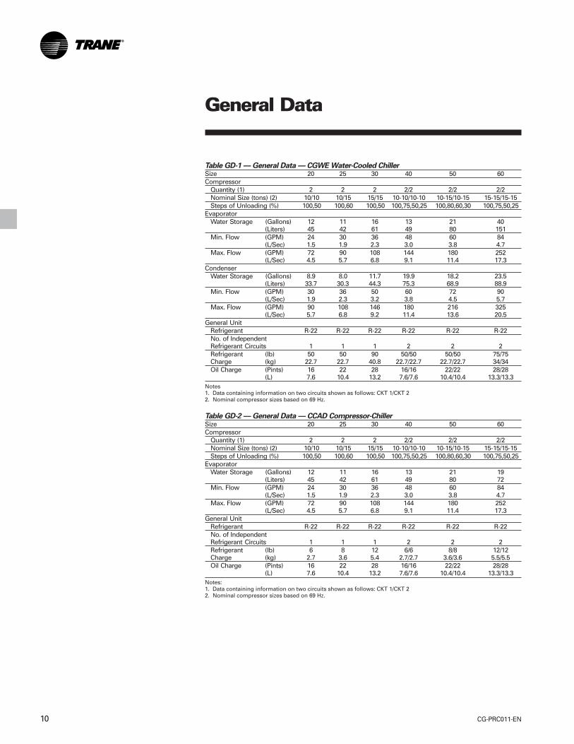
Table GD-1 — General Data — CGWE Water-Cooled ChillerSize 20 25 30 40 50 60Compressor
Quantity (1) 2 2 2 2/2 2/2 2/2Nominal Size (tons) (2) 10/10 10/15 15/15 10-10/10-10 10-15/10-15 15-15/15-15Steps of Unloading (%) 100,50 100,60 100,50 100,75,50,25 100,80,60,30 100,75,50,25
EvaporatorWater Storage (Gallons) 12 11 16 13 21 40
(Liters) 45 42 61 49 80 151Min. Flow (GPM) 24 30 36 48 60 84
(L/Sec) 1.5 1.9 2.3 3.0 3.8 4.7Max. Flow (GPM) 72 90 108 144 180 252
(L/Sec) 4.5 5.7 6.8 9.1 11.4 17.3Condenser
Water Storage (Gallons) 8.9 8.0 11.7 19.9 18.2 23.5(Liters) 33.7 30.3 44.3 75.3 68.9 88.9
Min. Flow (GPM) 30 36 50 60 72 90(L/Sec) 1.9 2.3 3.2 3.8 4.5 5.7
Max. Flow (GPM) 90 108 146 180 216 325(L/Sec) 5.7 6.8 9.2 11.4 13.6 20.5
General UnitRefrigerant R-22 R-22 R-22 R-22 R-22 R-22No. of IndependentRefrigerant Circuits 1 1 1 2 2 2Refrigerant (lb) 50 50 90 50/50 50/50 75/75Charge (kg) 22.7 22.7 40.8 22.7/22.7 22.7/22.7 34/34Oil Charge (Pints) 16 22 28 16/16 22/22 28/28
(L) 7.6 10.4 13.2 7.6/7.6 10.4/10.4 13.3/13.3Notes1. Data containing information on two circuits shown as follows: CKT 1/CKT 22. Nominal compressor sizes based on 69 Hz.
Table GD-2 — General Data — CCAD Compressor-ChillerSize 20 25 30 40 50 60Compressor
Quantity (1) 2 2 2 2/2 2/2 2/2Nominal Size (tons) (2) 10/10 10/15 15/15 10-10/10-10 10-15/10-15 15-15/15-15Steps of Unloading (%) 100,50 100,60 100,50 100,75,50,25 100,80,60,30 100,75,50,25
EvaporatorWater Storage (Gallons) 12 11 16 13 21 19
(Liters) 45 42 61 49 80 72Min. Flow (GPM) 24 30 36 48 60 84
(L/Sec) 1.5 1.9 2.3 3.0 3.8 4.7Max. Flow (GPM) 72 90 108 144 180 252
(L/Sec) 4.5 5.7 6.8 9.1 11.4 17.3General Unit
Refrigerant R-22 R-22 R-22 R-22 R-22 R-22No. of IndependentRefrigerant Circuits 1 1 1 2 2 2Refrigerant (lb) 6 8 12 6/6 8/8 12/12Charge (kg) 2.7 3.6 5.4 2.7/2.7 3.6/3.6 5.5/5.5Oil Charge (Pints) 16 22 28 16/16 22/22 28/28
(L) 7.6 10.4 13.2 7.6/7.6 10.4/10.4 13.3/13.3Notes:1. Data containing information on two circuits shown as follows: CKT 1/CKT 22. Nominal compressor sizes based on 69 Hz.
General Data
11CG-PRC011-EN
Unit LocationUnits should be installed indoors whereexposure to rain or water splash isminimal. A level foundation or flooringmust be provided which will support atleast 150 percent of the operating weightof the unit. The chiller foundation must berigid to reduce vibration transmission to aminimum. Use of vibration isolators isrecommended for applications withsensitive vibration and noise criteria.
Allow service clearance for compressorremoval as well as evaporator andcondenser tube removal.
Condenser Water LimitationsWater-cooled scroll chillers start andoperate satisfactorily over a range of loadconditions with uncontrolled enteringwater temperature.
Reducing the condenser watertemperature is an effective method oflowering the power input required.However, by reducing the condenserwater temperature beyond certain limits,the effect causes a reduction in thepressure drop across the thermalexpansion valve to a point when systeminstability may occur.
In general, continuous machine operationwith entering condenser watertemperature below 60°F [15.5°C] is notrecommended. When the condenserwater temperature is expected to dropbelow 60°F [15.5°C], it is recommendedthat some form of condenser watertemperature control be used to ensureoptimal machine performance.
Water TreatmentUse of untreated or improperly treatedwater in chillers may result in scaling,erosion, corrosion, algae or slime. It isrecommended that the services of aqualified water treatment specialist beengaged to determine what treatment, ifany, is advisable. Trane assumes noresponsibility for the results of untreated,or improperly treated water.
Water PumpsAvoid specifying or using 3600 rpm, 60Hz [3000 rpm, 50 Hz] condenser waterand chilled water pumps. Such pumpsmay operate with objectional noise andvibration. In addition, a low frequencybeat may occur due to the slightdifference in operating rpm betweenwater pumps and scroll compressormotors. Where noise and vibration-freeoperation is important, Traneencourages the use of 1750 rpm, 60 Hz[1450 rpm, 50 Hz] pumps.
Remote CondenserRemote condensers should be locatedas close as possible to the chiller toensure minimum pressure drops ofdischarge refrigerant. If non-Tranecondensers are provided, a subcoolingcircuit must be provided in order toachieve cataloged performances(16°F [-8.9°C] subcooling).
ApplicationConsiderations
CG-PRC011-EN12
SelectionProcedures
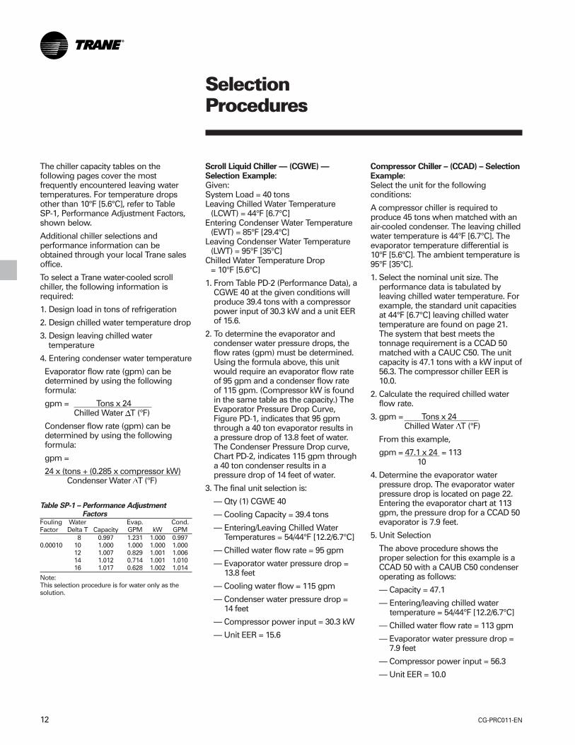
The chiller capacity tables on thefollowing pages cover the mostfrequently encountered leaving watertemperatures. For temperature dropsother than 10°F [5.6°C], refer to TableSP-1, Performance Adjustment Factors,shown below.
Additional chiller selections andperformance information can beobtained through your local Trane salesoffice.
To select a Trane water-cooled scrollchiller, the following information isrequired:
1. Design load in tons of refrigeration
2. Design chilled water temperature drop
3. Design leaving chilled watertemperature
4. Entering condenser water temperature
Evaporator flow rate (gpm) can bedetermined by using the followingformula:
gpm = Tons x 24 Chilled Water DT (°F)
Condenser flow rate (gpm) can bedetermined by using the followingformula:
gpm =
24 x (tons + (0.285 x compressor kW) Condenser Water DT (°F)
Scroll Liquid Chiller — (CGWE) —Selection Example:Given:System Load = 40 tonsLeaving Chilled Water Temperature
(LCWT) = 44°F [6.7°C]Entering Condenser Water Temperature
(EWT) = 85°F [29.4°C]Leaving Condenser Water Temperature
(LWT) = 95°F [35°C]Chilled Water Temperature Drop
= 10°F [5.6°C]
1. From Table PD-2 (Performance Data), aCGWE 40 at the given conditions willproduce 39.4 tons with a compressorpower input of 30.3 kW and a unit EERof 15.6.
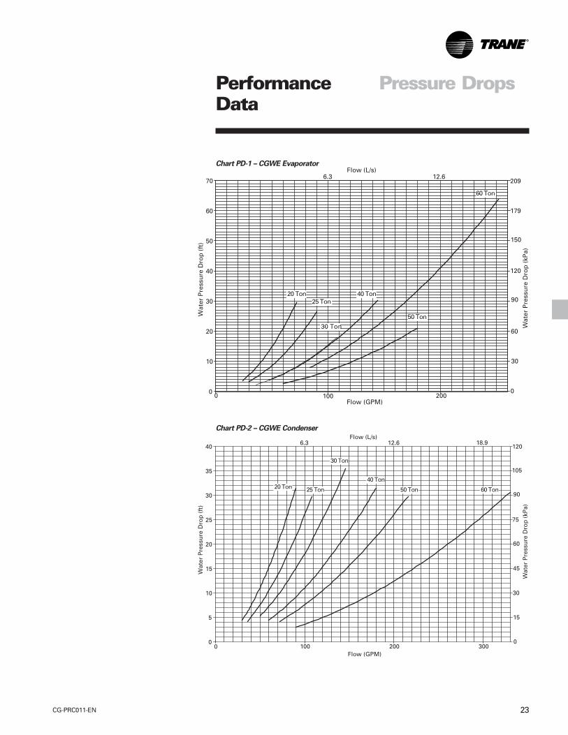
2. To determine the evaporator andcondenser water pressure drops, theflow rates (gpm) must be determined.Using the formula above, this unitwould require an evaporator flow rateof 95 gpm and a condenser flow rateof 115 gpm. (Compressor kW is foundin the same table as the capacity.) TheEvaporator Pressure Drop Curve,Figure PD-1, indicates that 95 gpmthrough a 40 ton evaporator results ina pressure drop of 13.8 feet of water.The Condenser Pressure Drop curve,Chart PD-2, indicates 115 gpm througha 40 ton condenser results in apressure drop of 14 feet of water.
3. The final unit selection is:
— Qty (1) CGWE 40
— Cooling Capacity = 39.4 tons
— Entering/Leaving Chilled Water Temperatures = 54/44°F [12.2/6.7°C]
— Chilled water flow rate = 95 gpm
— Evaporator water pressure drop = 13.8 feet
— Cooling water flow = 115 gpm
— Condenser water pressure drop = 14 feet
— Compressor power input = 30.3 kW
— Unit EER = 15.6
Compressor Chiller – (CCAD) – SelectionExample:Select the unit for the followingconditions:
A compressor chiller is required toproduce 45 tons when matched with anair-cooled condenser. The leaving chilledwater temperature is 44°F [6.7°C]. Theevaporator temperature differential is10°F [5.6°C]. The ambient temperature is95°F [35°C].
1. Select the nominal unit size. Theperformance data is tabulated byleaving chilled water temperature. Forexample, the standard unit capacitiesat 44°F [6.7°C] leaving chilled watertemperature are found on page 21.The system that best meets thetonnage requirement is a CCAD 50matched with a CAUC C50. The unitcapacity is 47.1 tons with a kW input of56.3. The compressor chiller EER is10.0.
2. Calculate the required chilled waterflow rate.
3. gpm = Tons x 24 Chilled Water DT (°F)
From this example,
gpm = 47.1 x 24 = 113 10
4. Determine the evaporator waterpressure drop. The evaporator waterpressure drop is located on page 22.Entering the evaporator chart at 113gpm, the pressure drop for a CCAD 50evaporator is 7.9 feet.
5. Unit Selection
The above procedure shows theproper selection for this example is aCCAD 50 with a CAUB C50 condenseroperating as follows:
— Capacity = 47.1
— Entering/leaving chilled water temperature = 54/44°F [12.2/6.7°C]
— Chilled water flow rate = 113 gpm
— Evaporator water pressure drop = 7.9 feet
— Compressor power input = 56.3
— Unit EER = 10.0
Table SP-1 – Performance AdjustmentFactors
Fouling Water Evap. Cond.Factor Delta T Capacity GPM kW GPM
8 0.997 1.231 1.000 0.9970.00010 10 1.000 1.000 1.000 1.000
12 1.007 0.829 1.001 1.00614 1.012 0.714 1.001 1.01016 1.017 0.628 1.002 1.014
Note:This selection procedure is for water only as thesolution.

13CG-PRC011-EN
Figure PAF-1 – Ethylene Glycol Performance Adjustment Factors
Figure PAF-2 – Propylene Glycol Performance Adjustment Factors
PerformanceAdjustment Factors

CG-PRC011-EN14
Table PAF-1 – Pressure Drop Correction FactorLeavingWater Percent Of Ethylene Glycol
Temperature 0 10 20 30 40 500 NA NA NA NA 1.50 1.60
10 NA NA NA 1.38 1.46 1.5520 NA NA 1.26 1.34 1.42 1.5130 NA 1.15 1.22 1.30 1.38 1.4740 1.00 1.12 1.19 1.26 1.34 1.4250 1.00 1.09 1.16 1.23 1.31 1.3960 1.00 1.05 1.09 1.12 1.16 1.21
Table PAF-2 – Pressure Drop Correction FactorLeavingWater Percent Of Propylene Glycol
Temperature 0 10 20 30 40 500 NA NA NA NA 1.63 1.90
10 NA NA NA 1.42 1.55 1.7420 NA NA 1.24 1.34 1.46 1.6230 NA 1.11 1.19 1.28 1.39 1.5340 1.00 1.07 1.15 1.23 1.33 1.4550 1.00 1.04 1.11 1.19 1.28 1.3960 1.00 1.00 1.03 1.08 1.13 1.20
Figure PAF-3 – Ethylene Glycol and Propylene Glycol Solution Freezing Points
PerformanceAdjustment Factors
15CG-PRC011-EN
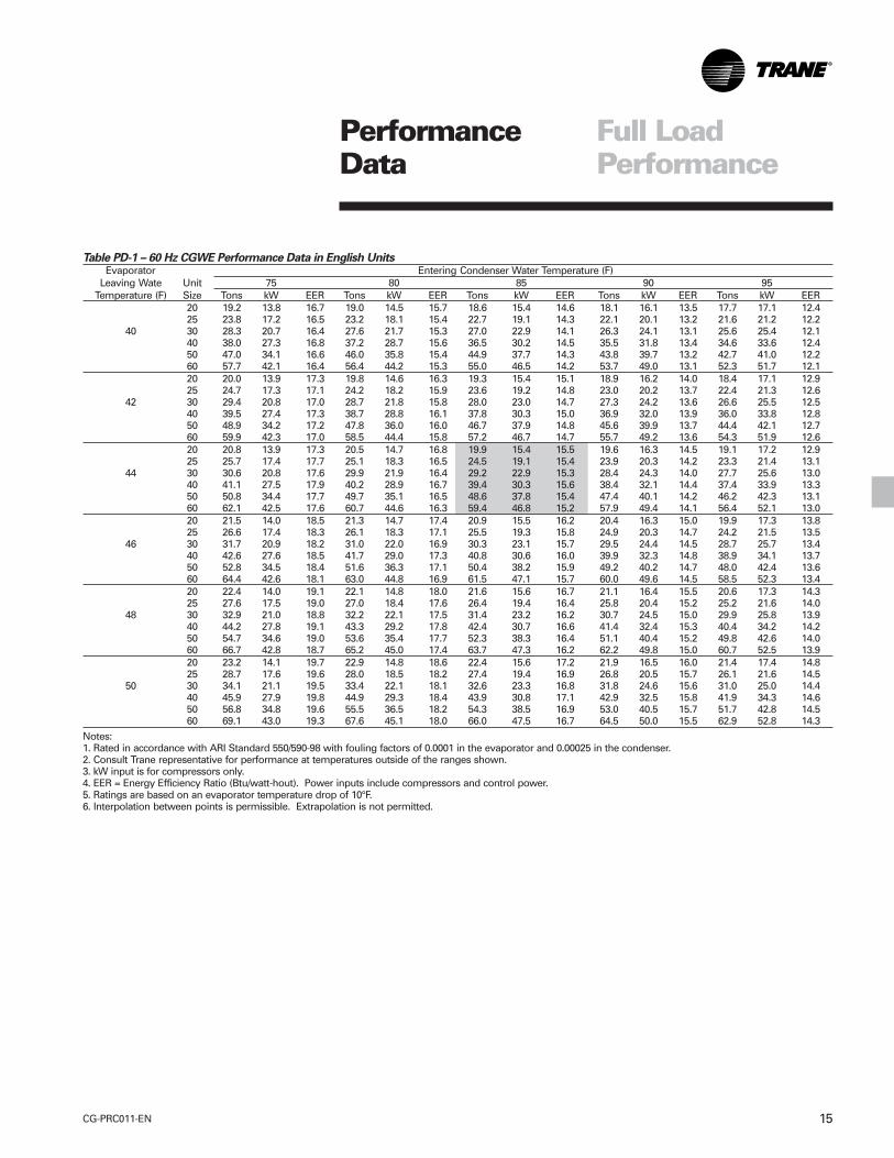
Table PD-1 – 60 Hz CGWE Performance Data in English UnitsEvaporator Entering Condenser Water Temperature (F)
Leaving Wate Unit 75 80 85 90 95Temperature (F) Size Tons kW EER Tons kW EER Tons kW EER Tons kW EER Tons kW EER
20 19.2 13.8 16.7 19.0 14.5 15.7 18.6 15.4 14.6 18.1 16.1 13.5 17.7 17.1 12.425 23.8 17.2 16.5 23.2 18.1 15.4 22.7 19.1 14.3 22.1 20.1 13.2 21.6 21.2 12.2
40 30 28.3 20.7 16.4 27.6 21.7 15.3 27.0 22.9 14.1 26.3 24.1 13.1 25.6 25.4 12.140 38.0 27.3 16.8 37.2 28.7 15.6 36.5 30.2 14.5 35.5 31.8 13.4 34.6 33.6 12.450 47.0 34.1 16.6 46.0 35.8 15.4 44.9 37.7 14.3 43.8 39.7 13.2 42.7 41.0 12.260 57.7 42.1 16.4 56.4 44.2 15.3 55.0 46.5 14.2 53.7 49.0 13.1 52.3 51.7 12.120 20.0 13.9 17.3 19.8 14.6 16.3 19.3 15.4 15.1 18.9 16.2 14.0 18.4 17.1 12.925 24.7 17.3 17.1 24.2 18.2 15.9 23.6 19.2 14.8 23.0 20.2 13.7 22.4 21.3 12.6
42 30 29.4 20.8 17.0 28.7 21.8 15.8 28.0 23.0 14.7 27.3 24.2 13.6 26.6 25.5 12.540 39.5 27.4 17.3 38.7 28.8 16.1 37.8 30.3 15.0 36.9 32.0 13.9 36.0 33.8 12.850 48.9 34.2 17.2 47.8 36.0 16.0 46.7 37.9 14.8 45.6 39.9 13.7 44.4 42.1 12.760 59.9 42.3 17.0 58.5 44.4 15.8 57.2 46.7 14.7 55.7 49.2 13.6 54.3 51.9 12.620 20.8 13.9 17.3 20.5 14.7 16.8 19.9 15.4 15.5 19.6 16.3 14.5 19.1 17.2 12.925 25.7 17.4 17.7 25.1 18.3 16.5 24.5 19.1 15.4 23.9 20.3 14.2 23.3 21.4 13.1
44 30 30.6 20.8 17.6 29.9 21.9 16.4 29.2 22.9 15.3 28.4 24.3 14.0 27.7 25.6 13.040 41.1 27.5 17.9 40.2 28.9 16.7 39.4 30.3 15.6 38.4 32.1 14.4 37.4 33.9 13.350 50.8 34.4 17.7 49.7 35.1 16.5 48.6 37.8 15.4 47.4 40.1 14.2 46.2 42.3 13.160 62.1 42.5 17.6 60.7 44.6 16.3 59.4 46.8 15.2 57.9 49.4 14.1 56.4 52.1 13.020 21.5 14.0 18.5 21.3 14.7 17.4 20.9 15.5 16.2 20.4 16.3 15.0 19.9 17.3 13.825 26.6 17.4 18.3 26.1 18.3 17.1 25.5 19.3 15.8 24.9 20.3 14.7 24.2 21.5 13.5
46 30 31.7 20.9 18.2 31.0 22.0 16.9 30.3 23.1 15.7 29.5 24.4 14.5 28.7 25.7 13.440 42.6 27.6 18.5 41.7 29.0 17.3 40.8 30.6 16.0 39.9 32.3 14.8 38.9 34.1 13.750 52.8 34.5 18.4 51.6 36.3 17.1 50.4 38.2 15.9 49.2 40.2 14.7 48.0 42.4 13.660 64.4 42.6 18.1 63.0 44.8 16.9 61.5 47.1 15.7 60.0 49.6 14.5 58.5 52.3 13.420 22.4 14.0 19.1 22.1 14.8 18.0 21.6 15.6 16.7 21.1 16.4 15.5 20.6 17.3 14.325 27.6 17.5 19.0 27.0 18.4 17.6 26.4 19.4 16.4 25.8 20.4 15.2 25.2 21.6 14.0
48 30 32.9 21.0 18.8 32.2 22.1 17.5 31.4 23.2 16.2 30.7 24.5 15.0 29.9 25.8 13.940 44.2 27.8 19.1 43.3 29.2 17.8 42.4 30.7 16.6 41.4 32.4 15.3 40.4 34.2 14.250 54.7 34.6 19.0 53.6 35.4 17.7 52.3 38.3 16.4 51.1 40.4 15.2 49.8 42.6 14.060 66.7 42.8 18.7 65.2 45.0 17.4 63.7 47.3 16.2 62.2 49.8 15.0 60.7 52.5 13.920 23.2 14.1 19.7 22.9 14.8 18.6 22.4 15.6 17.2 21.9 16.5 16.0 21.4 17.4 14.825 28.7 17.6 19.6 28.0 18.5 18.2 27.4 19.4 16.9 26.8 20.5 15.7 26.1 21.6 14.5
50 30 34.1 21.1 19.5 33.4 22.1 18.1 32.6 23.3 16.8 31.8 24.6 15.6 31.0 25.0 14.440 45.9 27.9 19.8 44.9 29.3 18.4 43.9 30.8 17.1 42.9 32.5 15.8 41.9 34.3 14.650 56.8 34.8 19.6 55.5 36.5 18.2 54.3 38.5 16.9 53.0 40.5 15.7 51.7 42.8 14.560 69.1 43.0 19.3 67.6 45.1 18.0 66.0 47.5 16.7 64.5 50.0 15.5 62.9 52.8 14.3
Notes:1. Rated in accordance with ARI Standard 550/590-98 with fouling factors of 0.0001 in the evaporator and 0.00025 in the condenser.2. Consult Trane representative for performance at temperatures outside of the ranges shown.3. kW input is for compressors only.4. EER = Energy Efficiency Ratio (Btu/watt-hout). Power inputs include compressors and control power.5. Ratings are based on an evaporator temperature drop of 10°F.6. Interpolation between points is permissible. Extrapolation is not permitted.
PerformanceData
Full LoadPerformance
CG-PRC011-EN16
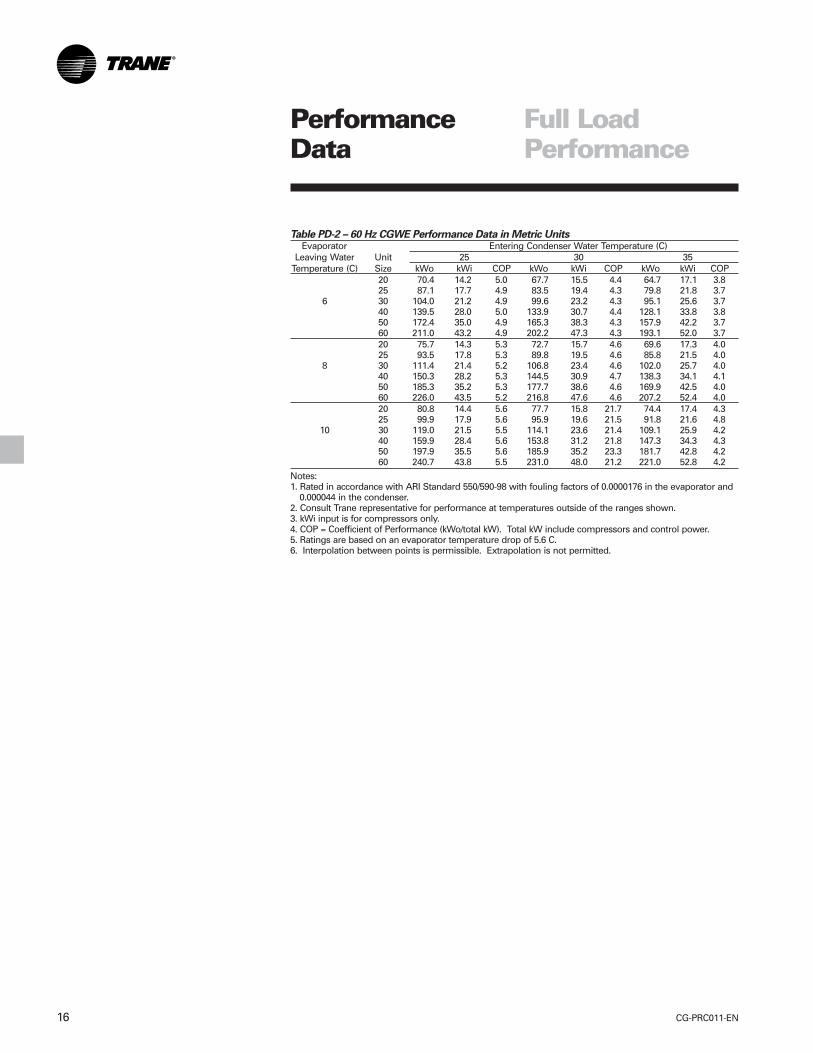
Table PD-2 – 60 Hz CGWE Performance Data in Metric UnitsEvaporator Entering Condenser Water Temperature (C)
Leaving Water Unit 25 30 35Temperature (C) Size kWo kWi COP kWo kWi COP kWo kWi COP
20 70.4 14.2 5.0 67.7 15.5 4.4 64.7 17.1 3.825 87.1 17.7 4.9 83.5 19.4 4.3 79.8 21.8 3.7
6 30 104.0 21.2 4.9 99.6 23.2 4.3 95.1 25.6 3.740 139.5 28.0 5.0 133.9 30.7 4.4 128.1 33.8 3.850 172.4 35.0 4.9 165.3 38.3 4.3 157.9 42.2 3.760 211.0 43.2 4.9 202.2 47.3 4.3 193.1 52.0 3.720 75.7 14.3 5.3 72.7 15.7 4.6 69.6 17.3 4.025 93.5 17.8 5.3 89.8 19.5 4.6 85.8 21.5 4.0
8 30 111.4 21.4 5.2 106.8 23.4 4.6 102.0 25.7 4.040 150.3 28.2 5.3 144.5 30.9 4.7 138.3 34.1 4.150 185.3 35.2 5.3 177.7 38.6 4.6 169.9 42.5 4.060 226.0 43.5 5.2 216.8 47.6 4.6 207.2 52.4 4.020 80.8 14.4 5.6 77.7 15.8 21.7 74.4 17.4 4.325 99.9 17.9 5.6 95.9 19.6 21.5 91.8 21.6 4.8
10 30 119.0 21.5 5.5 114.1 23.6 21.4 109.1 25.9 4.240 159.9 28.4 5.6 153.8 31.2 21.8 147.3 34.3 4.350 197.9 35.5 5.6 185.9 35.2 23.3 181.7 42.8 4.260 240.7 43.8 5.5 231.0 48.0 21.2 221.0 52.8 4.2
Notes:1. Rated in accordance with ARI Standard 550/590-98 with fouling factors of 0.0000176 in the evaporator and
0.000044 in the condenser.2. Consult Trane representative for performance at temperatures outside of the ranges shown.3. kWi input is for compressors only.4. COP = Coefficient of Performance (kWo/total kW). Total kW include compressors and control power.5. Ratings are based on an evaporator temperature drop of 5.6 C.6. Interpolation between points is permissible. Extrapolation is not permitted.
PerformanceData
Full LoadPerformance
17CG-PRC011-EN
PerformanceData
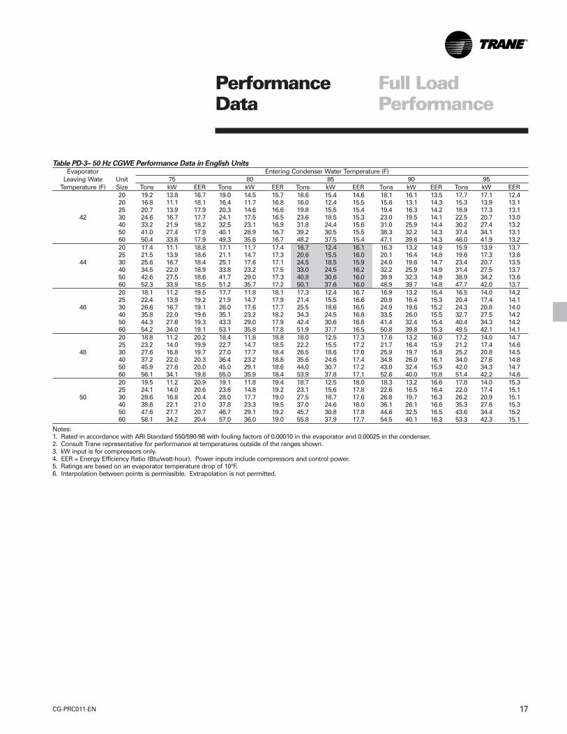
Table PD-3– 50 Hz CGWE Performance Data in English UnitsEvaporator Entering Condenser Water Temperature (F)
Leaving Wate Unit 75 80 85 90 95Temperature (F) Size Tons kW EER Tons kW EER Tons kW EER Tons kW EER Tons kW EER
20 19.2 13.8 16.7 19.0 14.5 15.7 18.6 15.4 14.6 18.1 16.1 13.5 17.7 17.1 12.420 16.8 11.1 18.1 16.4 11.7 16.8 16.0 12.4 15.5 15.6 13.1 14.3 15.3 13.9 13.125 20.7 13.9 17.9 20.3 14.6 16.6 19.8 15.5 15.4 19.4 16.3 14.2 18.9 17.3 13.1
42 30 24.6 16.7 17.7 24.1 17.5 16.5 23.6 18.5 15.3 23.0 19.5 14.1 22.5 20.7 13.040 33.2 21.9 18.2 32.5 23.1 16.9 31.8 24.4 15.6 31.0 25.9 14.4 30.2 27.4 13.250 41.0 27.4 17.9 40.1 28.9 16.7 39.2 30.5 15.5 38.3 32.2 14.3 37.4 34.1 13.160 50.4 33.8 17.9 49.3 35.6 16.7 48.2 37.5 15.4 47.1 39.6 14.3 46.0 41.9 13.220 17.4 11.1 18.8 17.1 11.7 17.4 16.7 12.4 16.1 16.3 13.2 14.9 15.9 13.9 13.725 21.5 13.9 18.6 21.1 14.7 17.3 20.6 15.5 16.0 20.1 16.4 14.8 19.6 17.3 13.6
44 30 25.6 16.7 18.4 25.1 17.6 17.1 24.5 18.5 15.9 24.0 19.6 14.7 23.4 20.7 13.540 34.5 22.0 18.9 33.8 23.2 17.5 33.0 24.5 16.2 32.2 25.9 14.9 31.4 27.5 13.750 42.6 27.5 18.6 41.7 29.0 17.3 40.8 30.6 16.0 39.9 32.3 14.8 38.9 34.2 13.660 52.3 33.9 18.5 51.2 35.7 17.2 50.1 37.6 16.0 48.9 39.7 14.8 47.7 42.0 13.720 18.1 11.2 19.5 17.7 11.8 18.1 17.3 12.4 16.7 16.9 13.2 15.4 16.5 14.0 14.225 22.4 13.9 19.2 21.9 14.7 17.9 21.4 15.5 16.6 20.9 16.4 15.3 20.4 17.4 14.1
46 30 26.6 16.7 19.1 26.0 17.6 17.7 25.5 18.6 16.5 24.9 19.6 15.2 24.3 20.8 14.040 35.8 22.0 19.6 35.1 23.2 18.2 34.3 24.5 16.8 33.5 26.0 15.5 32.7 27.5 14.250 44.3 27.6 19.3 43.3 29.0 17.9 42.4 30.6 16.6 41.4 32.4 15.4 40.4 34.3 14.260 54.2 34.0 19.1 53.1 35.8 17.8 51.9 37.7 16.5 50.8 39.8 15.3 49.5 42.1 14.120 18.8 11.2 20.2 18.4 11.8 18.8 18.0 12.5 17.3 17.6 13.2 16.0 17.2 14.0 14.725 23.2 14.0 19.9 22.7 14.7 18.5 22.2 15.5 17.2 21.7 16.4 15.9 21.2 17.4 14.6
48 30 27.6 16.8 19.7 27.0 17.7 18.4 26.5 18.6 17.0 25.9 19.7 15.8 25.2 20.8 14.540 37.2 22.0 20.3 36.4 23.2 18.8 35.6 24.6 17.4 34.8 26.0 16.1 34.0 27.6 14.850 45.9 27.6 20.0 45.0 29.1 18.6 44.0 30.7 17.2 43.0 32.4 15.9 42.0 34.3 14.760 56.1 34.1 19.8 55.0 35.9 18.4 53.9 37.8 17.1 52.6 40.0 15.8 51.4 42.2 14.620 19.5 11.2 20.9 19.1 11.8 19.4 18.7 12.5 18.0 18.3 13.2 16.6 17.8 14.0 15.325 24.1 14.0 20.6 23.6 14.8 19.2 23.1 15.6 17.8 22.6 16.5 16.4 22.0 17.4 15.1
50 30 28.6 16.8 20.4 28.0 17.7 19.0 27.5 18.7 17.6 26.8 19.7 16.3 26.2 20.9 15.140 38.6 22.1 21.0 37.8 23.3 19.5 37.0 24.6 18.0 36.1 26.1 16.6 35.3 27.6 15.350 47.6 27.7 20.7 46.7 29.1 19.2 45.7 30.8 17.8 44.6 32.5 16.5 43.6 34.4 15.260 58.1 34.2 20.4 57.0 36.0 19.0 55.8 37.9 17.7 54.5 40.1 16.3 53.3 42.3 15.1
Notes:1. Rated in accordance with ARI Standard 550/590-98 with fouling factors of 0.00010 in the evaporator and 0.00025 in the condenser.2. Consult Trane representative for performance at temperatures outside of the ranges shown.3. kW input is for compressors only.4. EER = Energy Efficiency Ratio (Btu/watt-hour). Power inputs include compressors and control power.5. Ratings are based on an evaporator temperature drop of 10°F.6. Interpolation between points is permissible. Extrapolation is not permitted.
Full LoadPerformance
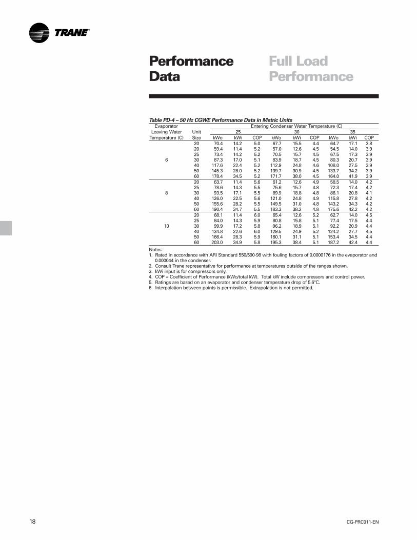
CG-PRC011-EN18
Table PD-4 – 50 Hz CGWE Performance Data in Metric UnitsEvaporator Entering Condenser Water Temperature (C)
Leaving Water Unit 25 30 35Temperature (C) Size kWo kWi COP kWo kWi COP kWo kWi COP
20 70.4 14.2 5.0 67.7 15.5 4.4 64.7 17.1 3.820 59.4 11.4 5.2 57.0 12.6 4.5 54.5 14.0 3.925 73.4 14.2 5.2 70.5 15.7 4.5 67.5 17.3 3.9
6 30 87.3 17.0 5.1 83.9 18.7 4.5 80.3 20.7 3.940 117.6 22.4 5.2 112.9 24.8 4.6 108.0 27.5 3.950 145.3 28.0 5.2 139.7 30.9 4.5 133.7 34.2 3.960 178.4 34.5 5.2 171.7 38.0 4.5 164.0 41.9 3.920 63.7 11.4 5.6 61.2 12.6 4.9 58.5 14.0 4.225 78.6 14.3 5.5 75.6 15.7 4.8 72.3 17.4 4.2
8 30 93.5 17.1 5.5 89.9 18.8 4.8 86.1 20.8 4.140 126.0 22.5 5.6 121.0 24.8 4.9 115.8 27.8 4.250 155.6 28.2 5.5 149.5 31.0 4.8 143.2 34.3 4.260 190.4 34.7 5.5 183.3 38.2 4.8 175.6 42.2 4.220 68.1 11.4 6.0 65.4 12.6 5.2 62.7 14.0 4.525 84.0 14.3 5.9 80.8 15.8 5.1 77.4 17.5 4.4
10 30 99.9 17.2 5.8 96.2 18.9 5.1 92.2 20.9 4.440 134.8 22.6 6.0 129.5 24.9 5.2 124.2 27.7 4.550 166.4 28.3 5.9 160.1 31.1 5.1 153.4 34.5 4.460 203.0 34.9 5.8 195.3 38.4 5.1 187.2 42.4 4.4
Notes:1. Rated in accordance with ARI Standard 550/590-98 with fouling factors of 0.0000176 in the evaporator and
0.000044 in the condenser.2. Consult Trane representative for performance at temperatures outside of the ranges shown.3. kWi input is for compressors only.4. COP = Coefficient of Performance (kWo/total kW). Total kW include compressors and control power.5. Ratings are based on an evaporator and condenser temperature drop of 5.6°C.6. Interpolation between points is permissible. Extrapolation is not permitted.
PerformanceData
Full LoadPerformance
19CG-PRC011-EN
PerformanceData
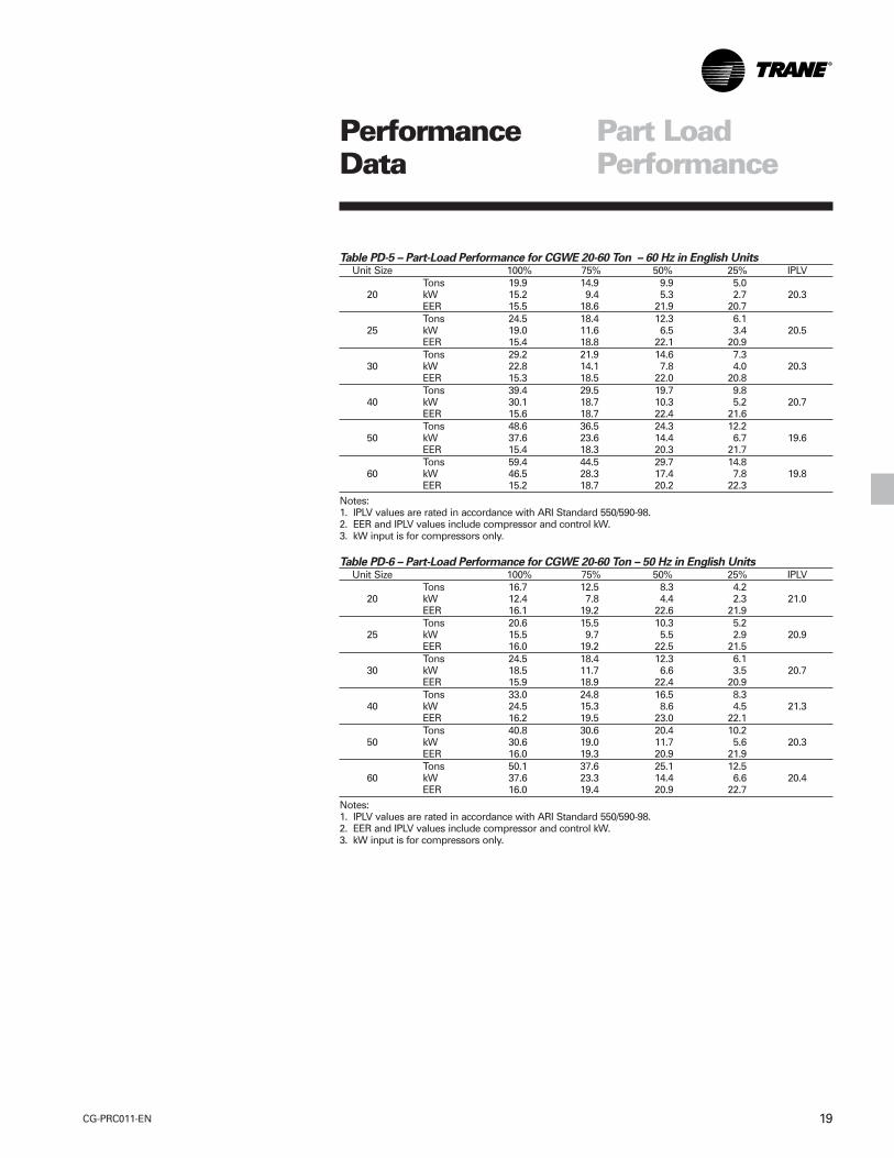
Part LoadPerformance
Table PD-5 – Part-Load Performance for CGWE 20-60 Ton – 60 Hz in English UnitsUnit Size 100% 75% 50% 25% IPLV
Tons 19.9 14.9 9.9 5.020 kW 15.2 9.4 5.3 2.7 20.3
EER 15.5 18.6 21.9 20.7Tons 24.5 18.4 12.3 6.1
25 kW 19.0 11.6 6.5 3.4 20.5EER 15.4 18.8 22.1 20.9Tons 29.2 21.9 14.6 7.3
30 kW 22.8 14.1 7.8 4.0 20.3EER 15.3 18.5 22.0 20.8Tons 39.4 29.5 19.7 9.8
40 kW 30.1 18.7 10.3 5.2 20.7EER 15.6 18.7 22.4 21.6Tons 48.6 36.5 24.3 12.2
50 kW 37.6 23.6 14.4 6.7 19.6EER 15.4 18.3 20.3 21.7Tons 59.4 44.5 29.7 14.8
60 kW 46.5 28.3 17.4 7.8 19.8EER 15.2 18.7 20.2 22.3
Notes:1. IPLV values are rated in accordance with ARI Standard 550/590-98.2. EER and IPLV values include compressor and control kW.3. kW input is for compressors only.
Table PD-6 – Part-Load Performance for CGWE 20-60 Ton – 50 Hz in English UnitsUnit Size 100% 75% 50% 25% IPLV
Tons 16.7 12.5 8.3 4.220 kW 12.4 7.8 4.4 2.3 21.0
EER 16.1 19.2 22.6 21.9Tons 20.6 15.5 10.3 5.2
25 kW 15.5 9.7 5.5 2.9 20.9EER 16.0 19.2 22.5 21.5Tons 24.5 18.4 12.3 6.1
30 kW 18.5 11.7 6.6 3.5 20.7EER 15.9 18.9 22.4 20.9Tons 33.0 24.8 16.5 8.3
40 kW 24.5 15.3 8.6 4.5 21.3EER 16.2 19.5 23.0 22.1Tons 40.8 30.6 20.4 10.2
50 kW 30.6 19.0 11.7 5.6 20.3EER 16.0 19.3 20.9 21.9Tons 50.1 37.6 25.1 12.5
60 kW 37.6 23.3 14.4 6.6 20.4EER 16.0 19.4 20.9 22.7
Notes:1. IPLV values are rated in accordance with ARI Standard 550/590-98.2. EER and IPLV values include compressor and control kW.3. kW input is for compressors only.

CG-PRC011-EN20
PerformanceData
Table PD-7 – 60 Hz CCAD Performance Data in English UnitsEvaporator Entering Condenser Air Temperature
Leaving Water Unit Condenser 85 95 105 115Temperature (°F) Size Size Tons kW EER Tons kW EER Tons kW EER Tons kW EER
20 CAUC-C20 19.4 19.5 11.8 18.4 21.6 10.1 17.3 23.9 8.6 16.1 26.6 7.220 CAUC-C25 19.7 18.6 12.6 18.7 20.6 10.8 17.6 23.0 9.1 16.5 25.5 7.725 CAUC-C25 24.1 24.9 11.5 22.8 27.6 9.9 21.5 30.6 8.4 20.0 34.0 7.025 CAUC-C30 24.5 23.4 12.5 23.3 26.0 10.7 22.0 28.9 9.1 20.6 32.1 7.7
42 30 CAUC-C30 28.8 29.1 11.8 27.3 32.2 10.1 25.7 35.7 8.6 24.1 39.6 7.330 CAUC-C40 29.2 27.0 12.9 27.8 29.9 11.1 26.3 33.2 9.5 24.7 36.9 8.040 CAUC-C40 38.7 38.8 11.9 36.7 43.0 10.2 34.5 47.8 8.6 32.2 53.2 7.240 CAUC-C50 39.1 37.4 12.5 37.1 41.6 10.6 35.0 46.2 9.0 32.7 51.4 7.650 CAUC-C50 47.6 50.2 11.3 45.1 55.6 9.7 42.5 61.8 8.2 39.7 68.4 6.950 CAUC-C60 48.4 47.0 12.3 46.0 52.2 10.5 43.5 58.2 8.9 40.8 64.6 7.660 CAUC-C60 56.9 58.4 11.6 54.0 64.8 10.0 50.9 71.8 8.5 47.6 79.8 7.160 CAUC-C80 57.5 53.6 12.8 54.7 59.6 11.0 51.8 66.4 9.3 48.6 73.8 7.920 CAUC-C20 20.0 19.7 12.1 19.0 21.8 10.4 17.8 24.2 8.8 16.6 26.8 7.420 CAUC-C25 20.4 18.8 12.9 19.3 20.8 11.0 18.2 23.2 9.3 17.1 25.7 7.925 CAUC-C25 24.9 25.1 11.8 23.6 27.9 10.1 22.2 30.9 8.6 20.7 34.3 7.225 CAUC-C30 25.3 23.7 12.7 24.1 26.3 10.9 22.7 29.2 9.3 21.3 32.4 7.9
44 30 CAUC-C30 29.7 29.4 12.1 28.2 32.6 10.3 26.6 36.1 8.8 24.9 40.0 7.430 CAUC-C40 30.2 27.2 13.2 28.8 30.2 11.4 27.2 33.5 9.7 25.6 37.2 8.240 CAUC-C40 39.9 39.2 12.1 37.8 43.4 10.4 35.6 48.2 8.8 33.3 53.6 7.440 CAUC-C50 40.3 37.8 12.7 38.3 42.0 10.9 36.1 46.6 9.2 33.8 51.8 7.850 CAUC-C50 49.1 50.6 11.6 46.6 56.2 9.9 43.9 62.2 8.4 41.0 69.0 7.150 CAUC-C60 50.0 47.4 12.6 47.5 52.6 10.8 44.9 58.6 9.2 42.2 65.2 7.760 CAUC-C60 58.7 58.5 12.0 55.7 65.4 10.2 52.6 72.6 8.7 49.2 80.6 7.360 CAUC-C80 59.3 54.0 13.1 56.5 60.0 11.3 53.5 66.8 9.6 50.3 74.4 8.120 CAUC-C20 20.7 19.9 12.4 19.6 22.0 10.6 18.4 24.4 9.0 17.2 27.1 7.620 CAUC-C25 21.0 18.9 13.2 20.0 21.0 11.3 18.8 23.4 9.6 17.6 25.9 8.125 CAUC-C25 25.7 25.4 12.1 24.3 28.2 10.3 22.9 31.2 8.8 21.4 34.6 7.425 CAUC-C30 26.2 23.9 13.1 24.9 26.5 11.2 23.5 29.5 9.5 22.0 32.6 8.1
46 30 CAUC-C30 30.7 29.7 12.3 29.1 32.9 10.6 27.5 36.4 9.0 25.7 40.4 7.630 CAUC-C40 31.2 27.4 13.6 29.7 30.4 11.7 28.2 33.8 10.0 26.5 37.5 8.440 CAUC-C40 41.1 38.6 12.7 39.0 43.8 10.6 36.8 48.8 9.0 34.4 54.0 7.640 CAUC-C50 41.6 38.0 13.1 39.5 42.2 11.2 37.3 47.0 9.5 35.0 52.2 8.050 CAUC-C50 50.6 51.2 11.8 48.0 56.6 10.1 45.3 62.8 8.6 42.3 69.8 7.250 CAUC-C60 51.6 47.8 12.9 49.1 53.2 11.0 46.4 59.0 9.4 43.6 65.6 7.960 CAUC-C60 60.5 59.4 12.2 57.5 66.0 10.4 54.3 73.2 8.9 50.9 81.2 7.560 CAUC-C80 61.2 54.4 13.4 58.3 60.6 11.5 55.2 67.4 9.8 52.0 75.0 8.3
Notes:1. Ratings based on sea level altitude and evaporator fouling factor of 0.00010.2. Consult Trane representative for performance at temperatures outside of the ranges shown.3. kW input is for compressors only.4. EER = Energy Efficiency Ratio (Btu/watt-hour). Power inputs include compressors and control power.5. Ratings are based on an evaporator temperature drop of 10°F.6. Interpolation between points is permissible. Extrapolation is not permitted.7. Rated in accordance with ARI Standard 550/590-98.
Full LoadPerformance
21CG-PRC011-EN
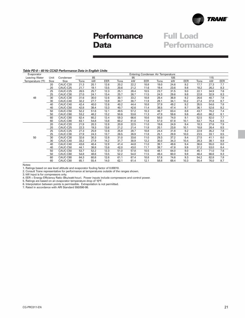
PerformanceData
Table PD-8 – 60 Hz CCAD Performance Data in English UnitsEvaporator Entering Condenser Air Temperature
Leaving Water Unit Condenser 85 95 105 115Temperature (°F) Size Size Tons kW EER Tons kW EER Tons kW EER Tons kW EER
20 CAUC-C20 21.3 20.1 12.6 20.2 22.2 10.8 19.0 24.6 9.2 17.7 27.3 7.720 CAUC-C25 21.7 19.1 13.5 20.6 21.2 11.6 19.4 23.6 9.8 18.2 26.2 8.325 CAUC-C25 26.5 25.7 12.3 25.1 28.4 10.5 23.7 31.5 9.0 22.1 34.9 7.625 CAUC-C30 27.0 24.1 13.4 25.7 26.7 11.5 24.3 29.6 9.8 22.8 32.9 8.3
48 30 CAUC-C30 31.6 30.0 12.6 30.1 33.2 10.8 28.4 36.8 9.2 26.6 40.7 7.830 CAUC-C40 32.2 27.7 13.9 30.7 30.7 11.9 29.1 34.1 10.2 27.4 37.8 8.740 CAUC-C40 42.4 40.0 12.6 40.2 44.4 10.8 37.9 49.2 9.2 35.5 54.6 7.840 CAUC-C50 42.8 38.4 13.3 40.7 42.6 11.4 38.5 47.4 9.7 36.1 52.6 8.250 CAUC-C50 52.2 51.6 12.1 49.5 57.2 10.3 46.7 63.4 8.8 43.7 70.2 7.450 CAUC-C60 53.2 48.2 13.2 50.6 53.6 11.3 47.9 59.6 9.6 45.0 66.2 8.160 CAUC-C60 62.4 60.2 12.4 59.3 66.6 10.6 56.0 74.0 9.1 52.5 82.0 7.760 CAUC-C80 63.1 54.8 13.8 60.2 61.8 11.8 57.0 67.8 10.1 53.7 75.4 8.520 CAUC-C20 21.9 20.3 12.8 20.8 22.5 11.0 19.6 24.9 9.4 18.3 27.6 7.920 CAUC-C25 22.3 19.3 13.8 21.2 21.4 11.8 20.1 23.8 10.1 18.8 26.4 8.525 CAUC-C25 27.3 25.9 12.6 25.9 28.7 10.8 24.4 31.8 9.2 22.9 35.2 7.825 CAUC-C30 27.9 24.3 13.7 26.5 26.9 11.8 25.1 29.9 10.0 23.5 33.1 8.5
50 30 CAUC-C30 32.6 30.3 12.8 31.0 33.6 11.0 29.3 37.2 9.4 27.5 41.1 8.030 CAUC-C40 33.2 27.9 14.2 31.7 30.9 12.2 30.0 34.3 10.4 28.3 38.1 8.940 CAUC-C40 43.6 40.4 12.9 41.4 44.8 11.0 39.1 49.6 9.4 36.6 55.0 8.040 CAUC-C50 44.1 38.8 13.6 42.0 43.0 11.7 39.7 47.8 9.9 37.2 53.0 8.450 CAUC-C50 53.7 52.2 12.3 51.0 57.8 10.5 48.1 64.0 9.0 45.1 71.0 7.650 CAUC-C60 54.8 48.6 13.5 52.2 54.0 11.5 49.4 60.0 9.8 46.4 66.6 8.360 CAUC-C60 64.3 60.8 12.6 61.1 67.4 10.8 57.8 74.6 9.3 54.2 82.8 7.860 CAUC-C80 65.1 55.4 14.0 62.1 61.4 12.1 58.8 68.4 10.3 55.4 76.0 8.7
Notes:1. Ratings based on sea level altitude and evaporator fouling factor of 0.00010.2. Consult Trane representative for performance at temperatures outside of the ranges shown.3. kW input is for compressors only.4. EER = Energy Efficiency Ratio (Btu/watt-hour). Power inputs include compressors and control power.5. Ratings are based on an evaporator temperature drop of 10°F.6. Interpolation between points is permissible. Extrapolation is not permitted.7. Rated in accordance with ARI Standard 550/590-98.
Full LoadPerformance
CG-PRC011-EN22
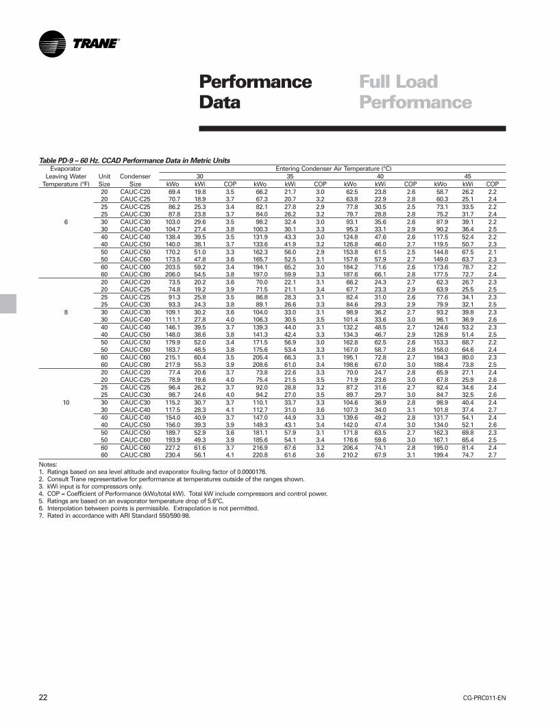
PerformanceData
Table PD-9 – 60 Hz. CCAD Performance Data in Metric UnitsEvaporator Entering Condenser Air Temperature (°C)
Leaving Water Unit Condenser 30 35 40 45Temperature (°F) Size Size kWo kWi COP kWo kWi COP kWo kWi COP kWo kWi COP
20 CAUC-C20 69.4 19.8 3.5 66.2 21.7 3.0 62.5 23.8 2.6 58.7 26.2 2.220 CAUC-C25 70.7 18.9 3.7 67.3 20.7 3.2 63.8 22.9 2.8 60.3 25.1 2.425 CAUC-C25 86.2 25.3 3.4 82.1 27.8 2.9 77.8 30.5 2.5 73.1 33.5 2.225 CAUC-C30 87.8 23.8 3.7 84.0 26.2 3.2 79.7 28.8 2.8 75.2 31.7 2.4
6 30 CAUC-C30 103.0 29.6 3.5 98.2 32.4 3.0 93.1 35.6 2.6 87.9 39.1 2.230 CAUC-C40 104.7 27.4 3.8 100.3 30.1 3.3 95.3 33.1 2.9 90.2 36.4 2.540 CAUC-C40 138.4 39.5 3.5 131.9 43.3 3.0 124.8 47.6 2.6 117.5 52.4 2.240 CAUC-C50 140.0 38.1 3.7 133.6 41.9 3.2 126.8 46.0 2.7 119.5 50.7 2.350 CAUC-C50 170.2 51.0 3.3 162.3 56.0 2.9 153.8 61.5 2.5 144.8 67.5 2.150 CAUC-C60 173.5 47.8 3.6 165.7 52.5 3.1 157.6 57.9 2.7 149.0 63.7 2.360 CAUC-C60 203.5 59.2 3.4 194.1 65.2 3.0 184.2 71.6 2.6 173.6 78.7 2.260 CAUC-C80 206.0 54.5 3.8 197.0 59.9 3.3 187.6 66.1 2.8 177.5 72.7 2.420 CAUC-C20 73.5 20.2 3.6 70.0 22.1 3.1 66.2 24.3 2.7 62.3 26.7 2.320 CAUC-C25 74.8 19.2 3.9 71.5 21.1 3.4 67.7 23.3 2.9 63.9 25.5 2.525 CAUC-C25 91.3 25.8 3.5 86.8 28.3 3.1 82.4 31.0 2.6 77.6 34.1 2.325 CAUC-C30 93.3 24.3 3.8 89.1 26.6 3.3 84.6 29.3 2.9 79.9 32.1 2.5
8 30 CAUC-C30 109.1 30.2 3.6 104.0 33.0 3.1 98.9 36.2 2.7 93.2 39.8 2.330 CAUC-C40 111.1 27.8 4.0 106.3 30.5 3.5 101.4 33.6 3.0 96.1 36.9 2.640 CAUC-C40 146.1 39.5 3.7 139.3 44.0 3.1 132.2 48.5 2.7 124.6 53.2 2.340 CAUC-C50 148.0 38.6 3.8 141.3 42.4 3.3 134.3 46.7 2.9 126.9 51.4 2.550 CAUC-C50 179.9 52.0 3.4 171.5 56.9 3.0 162.8 62.5 2.6 153.3 68.7 2.250 CAUC-C60 183.7 48.5 3.8 175.6 53.4 3.3 167.0 58.7 2.8 158.0 64.6 2.460 CAUC-C60 215.1 60.4 3.5 205.4 66.3 3.1 195.1 72.8 2.7 184.3 80.0 2.360 CAUC-C80 217.9 55.3 3.9 208.6 61.0 3.4 198.6 67.0 3.0 188.4 73.8 2.520 CAUC-C20 77.4 20.6 3.7 73.8 22.6 3.3 70.0 24.7 2.8 65.9 27.1 2.420 CAUC-C25 78.9 19.6 4.0 75.4 21.5 3.5 71.9 23.6 3.0 67.8 25.9 2.625 CAUC-C25 96.4 26.2 3.7 92.0 28.8 3.2 87.2 31.6 2.7 82.4 34.6 2.425 CAUC-C30 98.7 24.6 4.0 94.2 27.0 3.5 89.7 29.7 3.0 84.7 32.5 2.6
10 30 CAUC-C30 115.2 30.7 3.7 110.1 33.7 3.3 104.6 36.9 2.8 98.9 40.4 2.430 CAUC-C40 117.5 28.3 4.1 112.7 31.0 3.6 107.3 34.0 3.1 101.8 37.4 2.740 CAUC-C40 154.0 40.9 3.7 147.0 44.9 3.3 139.6 49.2 2.8 131.7 54.1 2.440 CAUC-C50 156.0 39.3 3.9 149.3 43.1 3.4 142.0 47.4 3.0 134.0 52.1 2.650 CAUC-C50 189.7 52.9 3.6 181.1 57.9 3.1 171.8 63.5 2.7 162.3 69.8 2.350 CAUC-C60 193.9 49.3 3.9 185.6 54.1 3.4 176.6 59.6 3.0 167.1 65.4 2.560 CAUC-C60 227.2 61.6 3.7 216.9 67.6 3.2 206.4 74.1 2.8 195.0 81.4 2.460 CAUC-C80 230.4 56.1 4.1 220.8 61.6 3.6 210.2 67.9 3.1 199.4 74.7 2.7
Notes:1. Ratings based on sea level altitude and evaporator fouling factor of 0.0000176.2. Consult Trane representative for performance at temperatures outside of the ranges shown.3. kWi input is for compressors only.4. COP = Coefficient of Performance (kWo/total kW). Total kW include compressors and control power.5. Ratings are based on an evaporator temperature drop of 5.6°C.6. Interpolation between points is permissible. Extrapolation is not permitted.7. Rated in accordance with ARI Standard 550/590-98.
Full LoadPerformance
23CG-PRC011-EN
PerformanceData
Chart PD-1 – CGWE Evaporator
Chart PD-2 – CGWE Condenser
Pressure Drops
CG-PRC011-EN24
Electrical Data
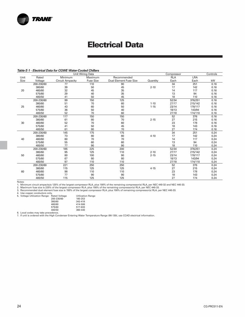
Table E-1 - Electrical Data for CGWE Water-Cooled ChillersUnit Wiring Data Compressor Controls
Unit Rated Minimum Maximum Recommended RLA LRASize Voltage Circuit Ampacity Fuse Size Dual Element Fuse Size Quantity Each Each kW
200-230/60 77 110 90 34 251 0.16380/60 39 50 45 2-10 17 142 0.16
20 460/60 32 45 35 14 117 0.16575/60 29 40 35 13 94 0.16400/50 41 50 45 18 110 0.16
200-230/60 99 150 125 52/34 376/251 0.16380/60 51 70 60 1-10 27/17 215/142 0.16
25 460/60 43 60 50 1-15 23/14 178/117 0.16575/60 36 50 40 18/13 143/94 0.16400/50 52 70 60 27/18 174/110 0.16
200-230/60 117 150 150 52 376 0.16380/60 61 80 70 2-15 27 215 0.16
30 460/60 52 70 60 23 178 0.16575/60 41 50 45 18 143 0.16400/50 61 80 70 27 174 0.16
200-230/60 145 175 175 34 251 0.24380/60 73 80 80 4-10 17 142 0.24
40 460/60 60 70 70 14 117 0.24575/60 55 60 60 13 94 0.24400/50 77 90 90 18 110 0.24
200-230/60 185 225 200 52/34 376/251 0.24380/60 95 125 110 2-10 27/17 215/142 0.24
50 460/60 80 100 90 2-15 23/14 178/117 0.24575/60 67 80 80 18/13 143/94 0.24400/50 97 110 110 27/18 174/110 0.24
200-230/60 221 250 250 52 376 0.24380/60 115 125 125 4-15 27 215 0.24
60 460/60 98 110 110 23 178 0.24575/60 77 90 90 18 143 0.24400/50 115 125 125 27 174 0.24
Notes:1. Minimum circuit ampacityis 125% of the largest compressor RLA, plus 100% of the remaining compressor(s) RLA, per NEC 440-32 and NEC 440-33.2. Maximum fuse size is 225% of the largest compressor RLA, plus 100% of the remaining compressor(s) RLA, per NEC 440-33.3. Recommended dual element fuse size is 150% of the largest compressor RLA, plus 100% of remaining compressor(s) RLA, per NEC 440-33.4. Use copper conductors only.5. Voltage Utilization Range: Rated Voltage Utilization Range
200-230/60 180-253380/60 342-418460/60 414-506575/60 517-633400/50 360-440
6. Local codes may take precedence.7. If unit is ordered with the High Condenser Entering Water Temperature Range (90-130), use CCAD electrical information.
25CG-PRC011-EN
Electrical Data
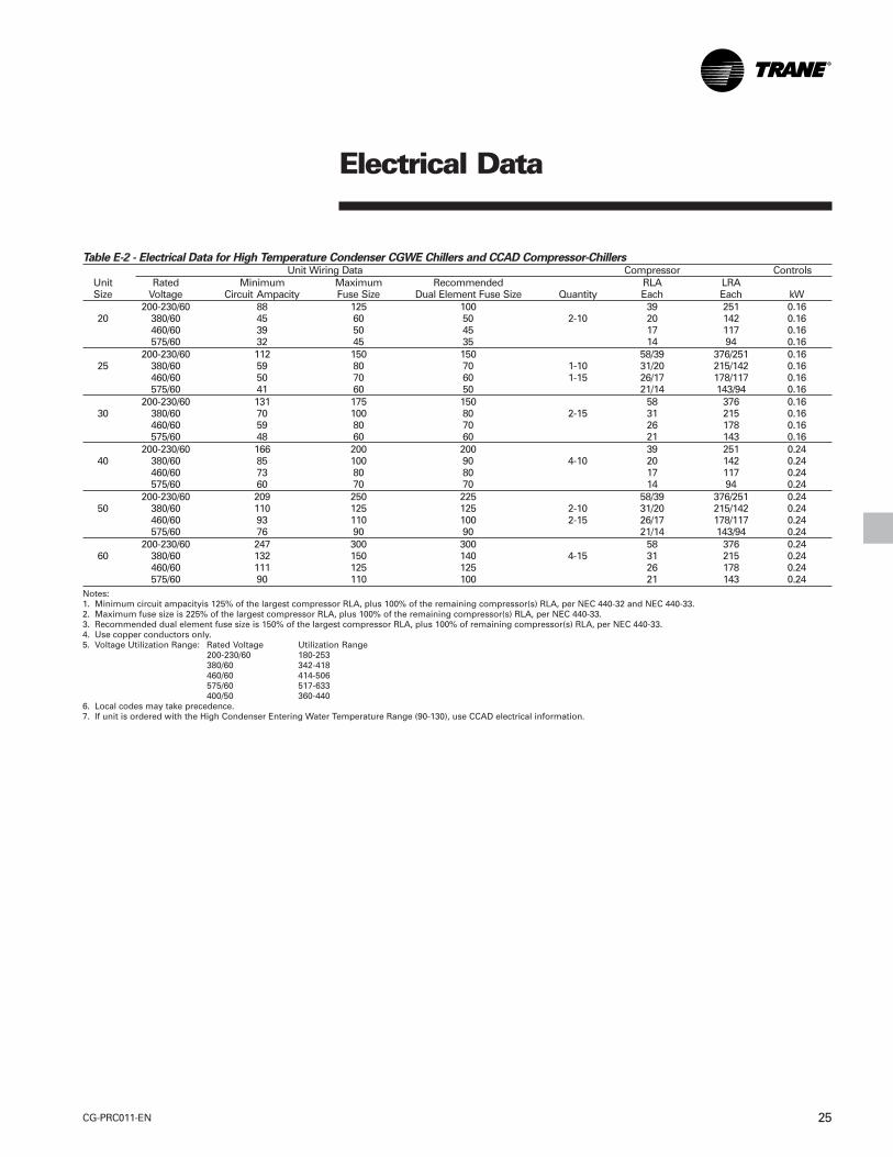
Table E-2 - Electrical Data for High Temperature Condenser CGWE Chillers and CCAD Compressor-ChillersUnit Wiring Data Compressor Controls
Unit Rated Minimum Maximum Recommended RLA LRASize Voltage Circuit Ampacity Fuse Size Dual Element Fuse Size Quantity Each Each kW
200-230/60 88 125 100 39 251 0.1620 380/60 45 60 50 2-10 20 142 0.16
460/60 39 50 45 17 117 0.16575/60 32 45 35 14 94 0.16
200-230/60 112 150 150 58/39 376/251 0.1625 380/60 59 80 70 1-10 31/20 215/142 0.16
460/60 50 70 60 1-15 26/17 178/117 0.16575/60 41 60 50 21/14 143/94 0.16
200-230/60 131 175 150 58 376 0.1630 380/60 70 100 80 2-15 31 215 0.16
460/60 59 80 70 26 178 0.16575/60 48 60 60 21 143 0.16
200-230/60 166 200 200 39 251 0.2440 380/60 85 100 90 4-10 20 142 0.24
460/60 73 80 80 17 117 0.24575/60 60 70 70 14 94 0.24
200-230/60 209 250 225 58/39 376/251 0.2450 380/60 110 125 125 2-10 31/20 215/142 0.24
460/60 93 110 100 2-15 26/17 178/117 0.24575/60 76 90 90 21/14 143/94 0.24
200-230/60 247 300 300 58 376 0.2460 380/60 132 150 140 4-15 31 215 0.24
460/60 111 125 125 26 178 0.24575/60 90 110 100 21 143 0.24
Notes:1. Minimum circuit ampacityis 125% of the largest compressor RLA, plus 100% of the remaining compressor(s) RLA, per NEC 440-32 and NEC 440-33.2. Maximum fuse size is 225% of the largest compressor RLA, plus 100% of the remaining compressor(s) RLA, per NEC 440-33.3. Recommended dual element fuse size is 150% of the largest compressor RLA, plus 100% of remaining compressor(s) RLA, per NEC 440-33.4. Use copper conductors only.5. Voltage Utilization Range: Rated Voltage Utilization Range
200-230/60 180-253380/60 342-418460/60 414-506575/60 517-633400/50 360-440
6. Local codes may take precedence.7. If unit is ordered with the High Condenser Entering Water Temperature Range (90-130), use CCAD electrical information.

CG-PRC011-EN26
NOTES:
1. DASHED LINES INDICATE RECOMMENDED FIELD WIRING BY OTHERS. PHANTOM LINES INDICATEALTERNATE CIRCUITRY OR AVAILABLE SALES OPTION. CHECK SALES ORDER TO DETERMINE IFWIRING IS REQUIRED FOR SPECIFIC OPTIONS.
2. ALL THREE PHASE MOTORS SUPPLIED WITH THE UNIT ARE PROTECTED UNDER PRIMARY SINGLEPHASE FAILURE CONDITIONS.
3. CAUTION - DO NOT ENERGIZE UNIT UNTIL CHECK OUT AND START-UP PROCEDURES HAVE BEENCOMPLETED.
4. THE FOLLOWING CAPABILITIES ARE OPTIONAL - THEY ARE IMPLEMENTED AND WIRED ASREQUIRED FOR A SPECIFIC SYSTEM APPLICATION.
A ICE-MACHINE CONTROL
B COMMUNICATIONS INTERFACE
G REMOTE RUNNING INDICATION AND ALARM CONTACTS
H UNIT DISCONNECT, NON-FUSED
J CHILLED WATER RESET - RETURN WATER
K CHILLED WATER RESET - OUTDOOR AIR TEMP. SENSOR OPTIONAL ON CGWE ANDSTANDARD ON CCAD.
L CHILLED WATER RESET - ZONE AIR
O LOW AMBIENT THERMOSTAT
P HIGH AMBIENT LOAD LIMIT THERMOSTAT
Q ENTERING AND LEAVING CONDENSER WATER TEMP. SENSOR. MATCHED PAIR OFTHERMISTORS. SENSOR KIT SHIPPED WITH UNIT AND FACTORY INSTALLED.
5. NOT USED ON 20-30 TON UNITS.
6. AUXILIARY CONTROLS FOR A CUSTOMER SPECIFIED OR INSTALLED LATCHING TRIPOUT. THECHILLER WILL RUN NORMALLY WHEN THE CONTACT IS CLOSED AND TRIP THE CHILLER OFF ONMANUALLY RESETTABLE DIAGNOSTIC WHEN THE CONTACT OPENS. MANUAL RESET ISACCOMPLISHED AT THE CHILLER SWITCH ON THE FRONT OF THE UNIT CONTROL MODULE(UCM).
7. AUXILIARY CONTROLS FOR A CUSTOMER SPECIFIED OR INSTALLED REMOTE AUTO/STOPFUNCTION. THE CHILLER WILL RUN NORMALLY WHEN THE CONTACT IS CLOSED AND STOP THECHILLER WHEN THE CONTACT IS OPEN. RE-CLOSURE OF THE CONTACT WILL PERMIT THECHILLER TO AUTOMATICALLY RETURN TO NORMAL OPERATION.
8. AUXILIARY CONTROLS FOR A CUSTOMER SPECIFIED OR INSTALLED DEMAND LIMIT FUNCTION.THE CHILLER WILL RUN NORMALLY WHEN THE CONTACT IS CLOSED AND LIMIT CHILLEROPERATION TO ONE COMPRESSOR PER CIRCUIT WHEN THE CONTACT OPENS. . RE-CLOSURE OFTHE CONTACT WILL PERMIT THE CHILLER TO AUTOMATICALLY RETURN TO NORMALOPERATION.
JobsiteConnections

27CG-PRC011-EN
WIRING :
10. ALL FIELD WIRING MUST BE IN ACCORDANCE WITH THE NATIONAL ELECTRICAL CODE (NEC),STATE, AND LOCAL REQUIREMENTS. OUTSIDE THE UNITED STATES, OTHER COUNTRIESAPPLICABLE NATIONAL AND/OR LOCAL REQUIREMENTS SHALL APPLY.
REQUIRED WIRING:
11 COPPER WIRE ONLY - SIZED PER N.E.C. - BASED ON NAMEPLATE RLA. SEE CUSTOMER WIRESELECTION TABLE.
12 2 WIRES, 115 VAC CIRCUIT. MINIMUM CONTACT RATING AT 115 VAC - 6.9 VA INRUSH. 1.3 VASEALED.
13 CCAD UNITS WITH AIR COOLED CONDENSER ONLY. 2 WIRES, 30 VOLT OR LESS CIRCUIT. DO NOTRUN IN CONDUIT WITH HIGHER VOLTAGE CIRCUITS. SEE CUSTOMER WIRE SELECTION TABLE.
OPTIONAL WIRING:
14 3 WIRES. 115 VAC CIRCUIT. SEPARATE 115 VAC POWER SUPPLY IS REQUIRED. LOAD NOT TOEXCEED 115 VA SEALED, 1150 VA INRUSH.
16 2 WIRES. 115 VAC CIRCUIT. MINIMUM CONTACT RATING AT 115 VAC - 6.9 VA INRUSH, 1.3 VASEALED.
17 3 WIRES ON 20-30 TON UNITS. 6 WIRES ON 40-60 TON UNITS. 115 VAC CIRCUIT. SEPARATE 115VAC POWER SUPPLY REQUIRED. LOAD NOT TO EXCEED 115 VA SEALED, 1150 VA INRUSH.
18 2 WIRES. 115 VAC CIRCUIT. SEPARATE 115 VAC POWER SUPPLY IS REQUIRED. LOAD NOT TOEXCEED 1150 VA INRUSH, 115 VA SEALED.
19 2 WIRES. 30 VOLT OR LESS CIRCUIT. DO NOT RUN IN CONDUIT WITH HIGHER VOLTAGECIRCUITS. SEE CUSTOMER WIRE SELECTION TABLE.
20 SHIELDED TWISTED PAIR, 30 V OR LESS CIRCUIT. MAXIMUM LENGTH 5000 FT. DO NOT RUN INCONDUIT WITH HIGHER VOLTAGE WIRE. SEE CUSTOMER WIRE SELECTION TABLE.
22 CUSTOMER SUPPLIED CONTACTS MUST BE COMPATIBLE WITH DRY CIRCUIT 12 VDC, 45 mARESISTIVE LOAD. SILVER OR GOLD PLATED CONTACTS ARE RECOMMENDED.
23 SENSOR LEADS TO REACH CONTROL PANEL. 30 VOLT OR LESS CIRCUIT. DO NOT RUN INCONDUIT WITH HIGHER VOLTAGE CIRCUITS.
JobsiteConnections
CG-PRC011-EN28
Controls
A microcomputer-based controllercontrols the CGWE and CCAD scrollchiller. The microcomputer controllerprovides better control than pastcontrols with several new, importantbenefits.
Customized ControlThe microcomputer-based controllerallows Trane to customize controlsaround the chiller application and thespecific components used in the scrollchiller. For instance, the compressorprotection system is specificallydesigned for the Trane scrollcompressor. The leaving chilled watertemperature control algorithm maintainsaccurate temperature control, minimizesthe drift from set point and providesbetter building comfort. Themicrocomputer control incorporatesimproved chiller start-up, load limiting,compressor anti-recycle timing and lead/lag functions into standard chilleroperation.
Simple Interface with OtherControl SystemsMicrocomputer controls afford simpleinterface with other control systems,such as time clocks, building automationsystems and ice storage systems. Wiringto the unit can be as simple as twowires! You can have the flexibility tomeet job requirements without learninga complicated control system.
Safety ControlsA centralized microcomputer offers ahigher level of machine protection. Sincethe safety controls are smarter,compressor operation can be limited toavoid compressor or evaporator failures,minimizing nuisance shutdown. Forinstance, if the head pressure on a unit isapproaching the trip point, the controllerwill turn off a compressor and display analarm to indicate a head pressureproblem. This keeps cooling capacityavailable until the problem can besolved. Whenever possible, the chiller isallowed to perform its function: makechilled water. In addition, microcomputercontrols allow for more types ofprotection as standard, such as over andunder voltage! Overall, the safetycontrols help keep the building runningand out of trouble.
Monitoring and DiagnosticsThe microcomputer provides all controlfunctions and can easily indicate suchparameters as leaving chilled watertemperature and capacity stage. If afailure does occur, one of over 40individual diagnostic codes will be usedto indicate the problem, giving morespecific information about the failure.The repair of the unit can occur in ashorter period of time. All of themonitoring and diagnostic information isdisplayed directly on a microcomputerdisplay.
Interface with the Trane IntegratedComfort™ System (ICS)When the scroll chiller is used inconjunction with a Trane Tracer™ system,the unit can be monitored and controlledfrom a remote location. The scroll chillercan be controlled to fit into the overallbuilding control strategy by using auto/stop, compressor inhibit and chilledwater reset functions.
All of the monitoring informationindicated on the microcomputer can beread off the Tracer system display. Inaddition, all the powerful diagnosticinformation can be read back at theTracer system.
Best of all, this powerful capabilitycomes over a single twisted pair ofwires!

29CG-PRC011-EN
DimensionalData
Size A B C D E F G H20 Ton 2" 8 1/2" 4'-8" 1'-3 3/8" 4 1/8" 8 5/8" 5 5/8" 2' 7 3/8"
(51) (216) (1423) (391) (105) (218) (143) (797)25 Ton 2" 8 1/2" 4'-8" 1'-3 3/8" 4 1/8" 8 5/8" 5 5/8" 2' 7 3/8"
(51) (216) (1423) (391) (105) (218) (143) (797)30 Ton 2 1/2" 7 3/4" 4'-6 1/2" 1'-5 3/8" 2 1/4" 12" 8" 2' 8 3/16"
(64) (197) (1384) (441) (57) (305) (203) (818)
Notes:1. Dimensions in ( ) are in millimeters.2. Dimensional tolerance ± 1/4” (3).
CGWE 20-30 Ton
CG-PRC011-EN30
DimensionalData
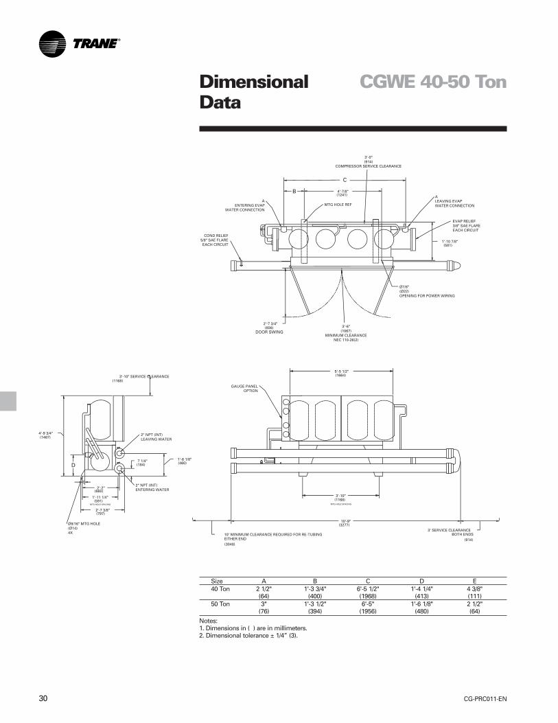
CGWE 40-50 Ton
Size A B C D E40 Ton 2 1/2" 1'-3 3/4" 6'-5 1/2" 1'-4 1/4" 4 3/8"
(64) (400) (1968) (413) (111)50 Ton 3" 1'-3 1/2" 6'-5" 1'-6 1/8" 2 1/2"
(76) (394) (1956) (480) (64)
Notes:1. Dimensions in ( ) are in millimeters.2. Dimensional tolerance ± 1/4” (3).
31CG-PRC011-EN
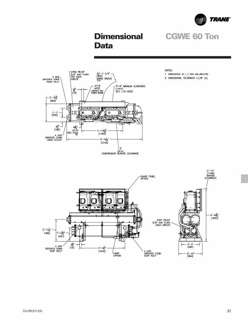
DimensionalData
CGWE 60 Ton
CG-PRC011-EN32
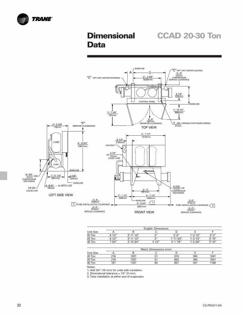
English DimensionsUnit Size A B C D E F20 Ton 8 1/2” 3’-11 1/2” 2” 2’-0” 1’-3 1/2” 3’-3”25 Ton 8 1/2” 3’-11 1/2” 2” 1’-11 3/4” 1’-3 1/2” 3’-10”30 Ton 7 3/4” 3’-10 3/4” 2 1/2” 2’-1 7/8” 1’-5 3/8” 3’-10”
Metric Dimensions (mm)Unit Size A B C D E F20 Ton 216 1207 51 610 394 104125 Ton 216 1207 51 603 394 104130 Ton 197 1187 64 657 441 1168
Notes:1. Add 3/4” (19 mm) for units with insulation.2. Dimensional tolerance ± 1/4” (3 mm).3. Tube installation at either end of evaporator.
DimensionalData
CCAD 20-30 Ton
33CG-PRC011-EN
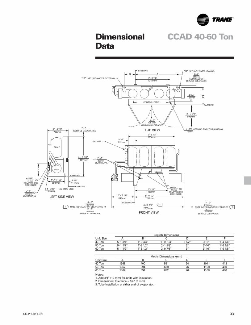
English DimensionsUnit Size A B C D E F40 Ton 5’-1 3/4” 1’-3 3/4” 1’-11 1/4” 2 1/2” 3’-5” 1’-4 1/4”50 Ton 5’-1 1/2” 1’-3 1/2” 2’-1 1/8” 3” 3’-10” 1’-6 1/8”60 Ton 5’-1 1/2” 1’-3 1/2” 2’-0 7/8” 3” 3’-10” 1’-6 1/8”
Metric Dimensions (mm)Unit Size A B C D E F40 Ton 1568 400 591 64 1041 41350 Ton 1562 394 638 76 1168 48060 Ton 1562 394 632 76 1168 460
Notes:1. Add 3/4” (19 mm) for units with insulation.2. Dimensional tolerance ± 1/4” (3 mm).3. Tube installation at either end of evaporator.
DimensionalData
CCAD 40-60 Ton
CG-PRC011-EN34
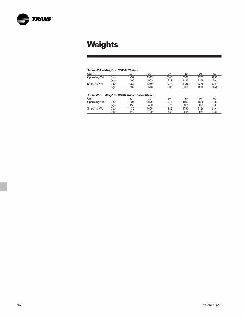
Weights
Table W-1 – Weights, CGWE ChillersUnit 20 25 30 40 50 60Operating Wt. (lb.) 1454 1517 2009 2506 2727 3753
(kg) 660 689 912 1138 1238 1704Shipping Wt. (lb.) 1282 1360 1774 2126 2376 3224
(kg) 582 618 806 965 1079 1464
Table W-2 – Weights, CCAD Compressor-ChillersUnit 20 25 30 40 50 60Operating Wt. (lb.) 1004 1079 1274 1509 1808 1982
(kg) 456 490 579 685 821 900Shipping Wt. (lb.) 1430 1605 1836 1792 2166 2494
(kg) 649 729 834 814 984 1133
35CG-PRC011-EN
Options
Hot Gas Bypass: Hot gas bypass optionallows unit operation below theminimum step of unit unloading. Theregulator valve, along with all associatedrefrigerant piping and electrical wiring,are factory installed and tested on onerefrigeration circuit. Unit does not start inhot gas bypass mode. If the unit operatesin bypass mode for 30 minutes without acall for cooling, it will pump down andshut off. Unit starts immediately upon afurther call for cooling.
Chilled Water Reset: Front panel settablecontrol, microprocessor based controlstrategy, and field-installed sensor fortemperature based (ambient or zone)reset are included in this option. Returnwater reset sensor is standard, but panelcontroller and control strategy must beordered as an option.
Communications Interface:Bi-directional (Trane ICS) and genericBAS (external chilled water setpoint)communication interfaces are availablefor external control applications.
Remote Display Panel: The remote panelhas the same digital display that is on theunit control panel as well as an auto/stopswitch. Another auto/stop switch can bewired from pump contactor or time clock(scheduling). Remote display is mutuallyexclusive with Trane ICS and genericBAS.
Remote Running Indication and AlarmContacts: Two separate single pole/double throw contacts are provided toindicate when the compressors arerunning and if a unit failure has occurred.A failure will be indicated if the unit has amanual reset fault. A failure is notindicated on an automatic reset fault.
Ice Making Controls: In ice-makingmode, the unit will operate fully loadedin response to jobsite supplied contactclosure. Ice making will terminate whenthe return fluid temperature falls belowan adjustable setpoint (minimum 20°F[-6.7°C]). When not in ice making mode,unit will provide modulating capacitycontrol based on leaving chilled fluidtemperature (20-55°F) [-6.7°C to 12.8°C].
Cycle Counter and Hour Meter: Onecycle counter and hour meter percompressor.
Unit Mounted Disconnect Switch: Non-fused molded case disconnect switchfactory installed in control panel fordisconnecting main three-phase power.
Isolators: Neoprene-in-shear isolators forfield installation under unit frame.
Gauges: Factory-installed gaugesmonitor suction and discharge pressure.One set of gauges per refrigerationcircuit.
Sound Attenuation: Factory-installedacoustical attenuation for applicationswhere extremely low sound level isrequired.
Water Regulating Valves: Field-installedvalves provide means for control of headpressure.
Low Ambient Thermostat: Field-installedoutdoor thermostat with an adjustablesetpoint provides means for low ambientlockout.
Condenser Water Temperature Sensor:Field-installed matched pair temperaturesensors provide for microprocessordisplay.
Options
CG-PRC011-EN36
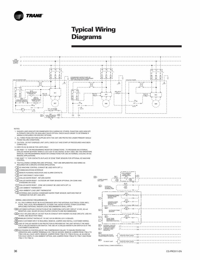
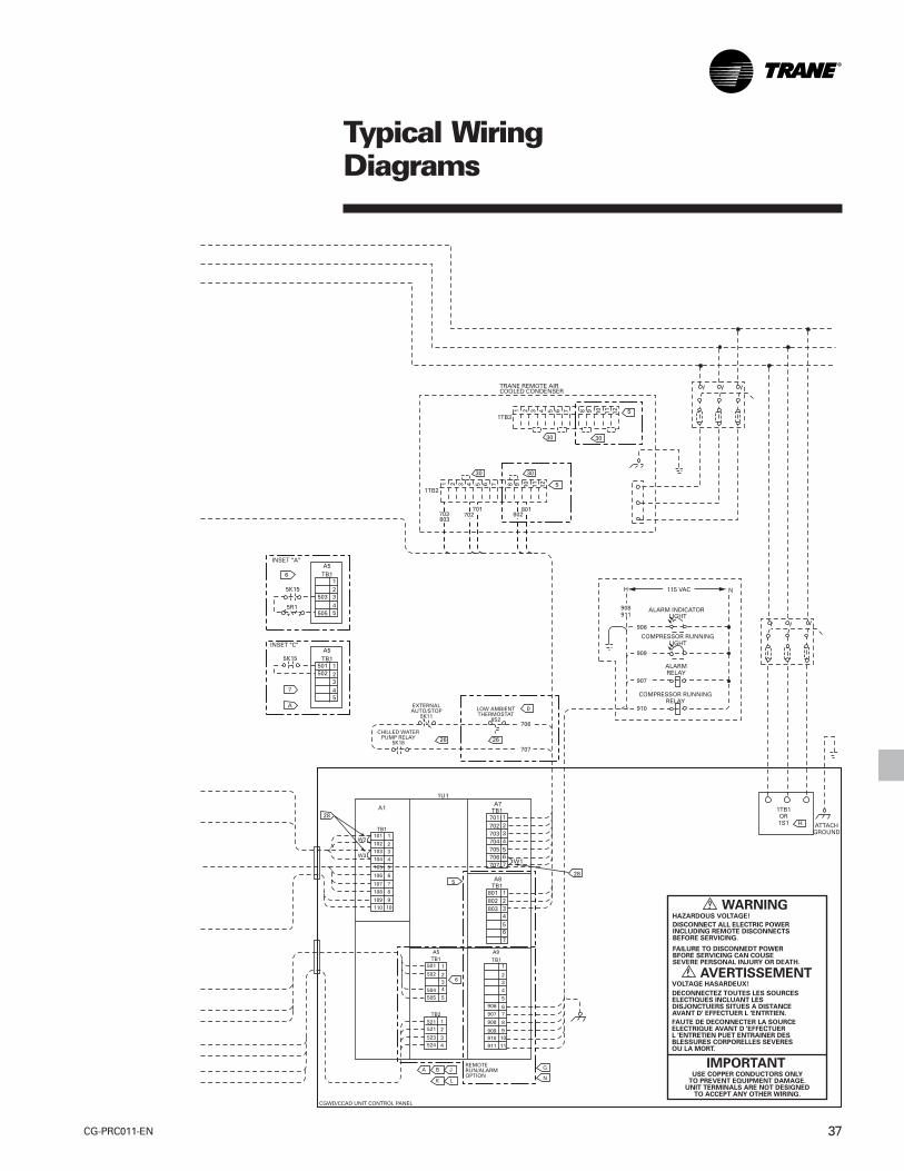
Typical WiringDiagrams
NOTES:
1. DASHED LINES INDICATE RECOMMENDED FIELD WIRING BY OTHERS. PHANTOM LINES INDICATEALTERNATE CIRCUITRY OR AVAILABLE SALES OPTION. CHECK SALES ORDER TO DETERMINE IFWIRING IS REQUIRED FOR SPECIFIC OPTIONS.
2. ALL THREE PHASE MOTORS SUPPLIED WITH THE UNIT ARE PROTECTED UNDER PRIMARY SINGLEPHASE FAILURE CONDITIONS.
4. CAUTION - DO NOT ENERGIZE UNIT UNTIL CHECK OUT AND START-UP PROCEDURES HAVE BEENCOMPLETED.
5. USED ON 40, 50 AND 60 TON UNITS ONLY.
6. SEE INSET “A” FOR PROGRAMMING RESISTOR CONNECTIONS . TO PROGRAM AN EXTERNALCHILLED WATER SETPOINT WHEN A 4-20 mA/0-10 VDC SIGNAL IS NOT USED. SEE THE OPERATORSMANUAL FOR PROGRAMMING RESISTOR CONNECTIONS FOR USE ON NORMAL COOLING OR ICEMAKING APPLICATIONS.
7. SEE INSET “C” FOR CONTACTS (IN PLACE OF ZONE TEMP. SENSOR) FOR OPTIONAL ICE MACHINECONTROL.
8. THE FOLLOWING CAPABILITIES ARE OPTIONAL - THEY ARE IMPLEMENTED AND WIRED ASREQUIRED FOR A SPECIFIC SYSTEM APPLICATION.
A ICE-MACHINE CONTROL (CANNOT BE USED WITH OPT. L)
B COMMUNICATIONS INTERFACE
G REMOTE RUNNING INDICATION AND ALARM CONTACTS
H UNIT DISCONNECT, NON-FUSED
J CHILLED WATER RESET - RETURN WATER
K CHILLED WATER RESET - OUTDOOR AIR TEMP. SENSOR OPTIONAL ON CGWE ANDSTANDARD ON CCAD.
L CHILLED WATER RESET - ZONE AIR (CANNOT BE USED WITH OPT. A)
O LOW AMBIENT THERMOSTAT
P HIGH AMBIENT LOAD LIMIT THERMOSTAT
Q ENTERING AND LEAVING CONDENSER WATER TEMP. SENSOR. MATCHED PAIR OFTHERMISTOR FOR 4RT1 AND 4RT2.
WIRING AND CONTACT REQUIREMENTS:
21. ALL FIELD WIRING MUST BE IN ACCORDANCE WITH THE NATIONAL ELECTRICAL CODE (NEC),STATE, AND LOCAL REQUIREMENTS. OUTSIDE THE UNITED STATES, OTHER COUNTRIESAPPLICABLE NATIONAL AND/OR LOCAL REQUIREMENTS SHALL APPLY.
24. CUSTOMER SUPPLIED CONTACTS MUST BE COMPATIBLE WITH DRY CIRCUIT 12 VDC, 45 mARESISTIVE LOAD. SILVER OR GOLD PLATED CONTACTS ARE RECOMMENDED.
25. 30 VOLT OR LESS CIRCUIT. DO NOT RUN IN CONDUIT WITH HIGHER VOLTAGE CIRCUITS. USE #14-18 AWG. SEE SELECTION TABLE.
26. MINIMUM CONTACT RATING AT 115 VAC: 6.9 VA INRUSH, 6.9 V A SEALED.
28. WHEN CUSTOMER INPUT IS REQUIRED, REMOVE JUMPER AND INSTALL CUSTOMER WIRING.
29. LOSS OF CHILLED WATER FLOW PROTECTION IS PROVIDED BY THE UNIT WITHOUT THE NEEDFOR A CHILLED WATER FLOW SWITCH. THE USE OF A CHILLED WATER FLOW SWITCH IS AT THECUSTOMER’S DISCRETION.
30. FAN STAGING IS CONTROLLED BY THE COMPRESSOR CHILLER. TO INSURE PROPER FANOPERATION ADD JUMPER TERMINALS ON 1TB3 AS SHOWN. REMOVE JUMPER FROM 1TB2-4 TO1TB2-3 ON ALL CAUC UNITS. REMOVE JUMPER FROM 1TB2-9 TO 1TB2-8 ON ALL 40, 50 AND 60TON CAUC UNITS. IF LOW AMBIENT OPTION, ADD JUMPER FROM 1TB3-6 TO 1TB3-7 AND FROM1TB3-11 TO 1TB3-12.
37CG-PRC011-EN
Typical WiringDiagrams
CG-PRC011-EN38
Advanced Design for Efficiency andReliability
• Trane scroll compressor has 64 percentfewer parts than equal capacityreciprocating compressors for greaterreliability. Part load efficiency isunmatched by any reciprocatingcompressor.
• Factory installed microprocessorcontrols provides accurate chilled watertemperature control. Themicroprocessor also incorporatesoptimal start-up logic, load limiting,compressor anti-recycle timing,automatic lead-lag function andcompressor protection features.
• Easy operation provided by menu-driven digital display. Display providestemperatures, pressures, setpoints andover 40 diagnostic readouts.
• Compressor protection from start andrun overloads, under and over voltage,phase loss and phase reversal, andrapid recycling.
• Easy installation through small size,factory wiring, easy lifting provisionsand start-up control logic.
• Availability. Trane has the industry’sfastest ship cycles on both stock andbuilt-to-order units.
• Other standard features include:— Control power transformer— Auto lead-lag (on or off)— Solid-state motor protection— Insulation— Condenser water pump interlock— Filter-dryer— Built-in loss of chilled water flow
sensors— Chillers fit through standard single-
width door
• Options— Trane Integrated Comfort™ systems
communication— Generic building automation
systems (BAS) interface— Chilled water reset (ambient, zone,
return)— Unit mounted disconnect— Ice making— Hot gas bypass— Remote display/control panel— Remote running indication and
alarm contact— Gauges— Sound attenuation— Neoprene isolators— Compressor cycle counter/hour
meter— Water regulating valves— Condenser water temperature
sensors
FeaturesSummary
39CG-PRC011-EN
Water-Cooled Liquid Chillers andCompressor Chillers CGWE and CCADModels 20 to 60 Tons
GeneralAll scroll chillers are factory tested andmonitored for power and controloperation (CGWE only). CGWE unitsship with a full operating charge ofrefrigerant and oil. Exposed surfaces arepainted with an air-dry beige primer-finisher prior to shipment.
Compressor-MotorDirect-drive, hermetic, 3600 rpm, 60 Hz[300 rpm, 60 Hz] fixed compression,scroll compressors (20 to 30 tons - twocompressors; 40 to 60 tons - fourcompressors). Each compressor has:centrifugal oil pump, oil level sightglass,oil charging valve, two point lubricationfor each motor bearing, floodedlubrication for the journal and thrustbearings, and a check valve on the scrolldischarge port.
Motor is suction gas-cooled,hermetically sealed, two-pole, squirrelcage induction type.
EvaporatorShell and tube design with seamlesscopper tubes roller expanded into tubesheets. Designed, tested and stamped inaccordance with ASME Code forrefrigerant side working pressure of 300psig. Water side working pressure is 300psig for CGWE 20-50 and CCAD 20-60,215 psig for CGWE 60. One water passwith a series of internal baffles. Eachshell includes drain connections,entering and leaving temperaturesensors, and ¾ inch Armaflex II (orequal) insulation (K= 0.26).
Condenser (CGWE only)Shell and tube design with seamlessinternally enhanced copper tubes.Designed and tested for refrigerant sideworking pressure of 450 psig. Waterside working pressure is 300 psig forCGWE 20-50, 150 psig for CGWE 60.Two pass construction with six-inchdiameter shell (20 to 30 tons). One passconstruction with two separatecondensers connected in series (40 to 60tons). Each condenser includes asubcooler circuit. Tubes are cleanableand replaceable.
Refrigerant CircuitEach refrigeration circuit shall becompletely independent and shallinclude liquid line and discharge lineservice valves, filter dryer, combinationmoisture indicator-sightglass, chargingport, insulated suction line, liquid linesolenoid valve and thermal expansionvalve.
Isolation valves provide means ofisolating refrigerant charge in either thehigh or low pressure side whileservicing. One refrigerant circuit on20 to 30 tons; two refrigerant circuits on40 to 60 tons.
Condenserless units (CCAD) shall beequipped with discharge check valveand moisture indicator sightglass.
Control PanelFactory-mounted microprocessor basedcontrol panel uses 120/60/1 power.Automatic shutdown protection withmanual reset is provided for lowevaporator outlet refrigeranttemperature and pressure, highcondenser refrigerant pressure, motorcurrent overload, and phase reversal.Automatic shutdown protection withautomatic reset after condition iscorrected is provided for low line voltageand loss of chilled water flow.
The unit control module (UCM)automatically takes action to preventcomplete shutdown by sheddingcompressors one at a time. This occursin the event of low evaporator refrigeranttemperature, high condenser refrigerantpressure, motor current overload;preventing the motor current fromexceeding setpoint.
Solid-state chilled water temperaturesensors are included for precise andaccurate control. A menu driven displayindicates the operating code, the lastdiagnostic code, chilled water setpoint,current limit setpoint, condenser waterand chilled water temperature sensors.Factory-installed entering and leavingcondenser water temperature sensors(optional) are available formicroprocessor display or Trane Tracer™
monitoring. Over 40 diagnostic checksare made and will be displayed when aproblem is detected.
StarterThe unit control panel contains both acontrol section and a starter section. Thepanel is a painted, NEMA 1 enclosure.The starter section contains: top accessfor power wiring, single point powerhook-up, three-phase solid-stateoverload protection, customer wiredgrounding lug, and control powertransformer with fused protection.
MechanicalSpecifications
Since Trane has a policy of continuous product and product data improvement, it reserves the right tochange design and specifications without notice.
Literature Order Number
File Number
Supersedes
Stocking LocationTrane
An American Standard Company
www.trane.com
For more information contactyour local sales office ore-mail us at [email protected]
CG-PRC011-EN
CG-PRC011-EN-0102
New
La Crosse