scion xb 2008 supercharger preparation - sparks...
TRANSCRIPT
SCION xB 2008 SUPERCHARGER Preparation
Issue A: 04/28/08 Page 1 of 48
2008-- Scion xB Supercharger – 2.4L
Installation Instructions
SCION xB 2008 SUPERCHARGER Preparation
Issue A: 04/28/08 Page 2 of 48
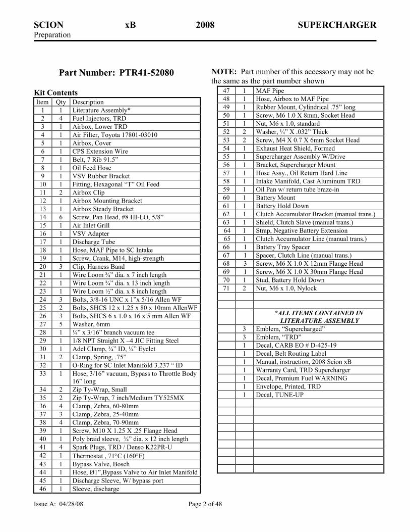
Part Number: PTR41-52080 NOTE: Part number of this accessory may not be
the same as the part number shown
Kit Contents Item Qty Description
1 1 Literature Assembly*
2 4 Fuel Injectors, TRD
3 1 Airbox, Lower TRD
4 1 Air Filter, Toyota 17801-03010
5 1 Airbox, Cover
6 1 CPS Extension Wire
7 1 Belt, 7 Rib 91.5”
8 1 Oil Feed Hose
9 1 VSV Rubber Bracket
10 1 Fitting, Hexagonal “T” Oil Feed
11 2 Airbox Clip
12 1 Airbox Mounting Bracket
13 1 Airbox Steady Bracket
14 6 Screw, Pan Head, #8 HI-LO, 5/8”
15 1 Air Inlet Grill
16 1 VSV Adapter
17 1 Discharge Tube
18 1 Hose, MAF Pipe to SC Intake
19 1 Screw, Crank, M14, high-strength
20 3 Clip, Harness Band
21 1 Wire Loom ¾” dia. x 7 inch length
22 1 Wire Loom ¾” dia. x 13 inch length
23 1 Wire Loom ½” dia. x 8 inch length
24 3 Bolts, 3/8-16 UNC x 1”x 5/16 Allen WF
25 2 Bolts, SHCS 12 x 1.25 x 80 x 10mm AllenWF
26 3 Bolts, SHCS 6 x 1.0 x 16 x 5 mm Allen WF
27 5 Washer, 6mm
28 1 ¼” x 3/16” branch vacuum tee
29 1 1/8 NPT Straight X –4 JIC Fitting Steel
30 1 Adel Clamp, ¾” ID, ¼” Eyelet
31 2 Clamp, Spring, .75”
32 1 O-Ring for SC Inlet Manifold 3.237 “ ID
33 1 Hose, 3/16” vacuum, Bypass to Throttle Body
16” long
34 2 Zip Ty-Wrap, Small
35 2 Zip Ty-Wrap, 7 inch/Medium TY525MX
36 4 Clamp, Zebra, 60-80mm
37 3 Clamp, Zebra, 25-40mm
38 4 Clamp, Zebra, 70-90mm
39 1 Screw, M10 X 1.25 X .25 Flange Head
40 1 Poly braid sleeve, ¾” dia. x 12 inch length
41 4 Spark Plugs, TRD / Denso K22PR-U
42 1 Thermostat , 71°C (160°F)
43 1 Bypass Valve, Bosch
44 1 Hose, Ø1”,Bypass Valve to Air Inlet Manifold
45 1 Discharge Sleeve, W/ bypass port
46 1 Sleeve, discharge
47 1 MAF Pipe
48 1 Hose, Airbox to MAF Pipe
49 1 Rubber Mount, Cylindrical .75” long
50 1 Screw, M6 1.0 X 8mm, Socket Head
51 1 Nut, M6 x 1.0, standard
52 2 Washer, ¼” X .032” Thick
53 2 Screw, M4 X 0.7 X 6mm Socket Head
54 1 Exhaust Heat Shield, Formed
55 1 Supercharger Assembly W/Drive
56 1 Bracket, Supercharger Mount
57 1 Hose Assy., Oil Return Hard Line
58 1 Intake Manifold, Cast Aluminum TRD
59 1 Oil Pan w/ return tube braze-in
60 1 Battery Mount
61 1 Battery Hold Down
62 1 Clutch Accumulator Bracket (manual trans.)
63 1 Shield, Clutch Slave (manual trans.)
64 1 Strap, Negative Battery Extension
65 1 Clutch Accumulator Line (manual trans.)
66 1 Battery Tray Spacer
67 1 Spacer, Clutch Line (manual trans.)
68 3 Screw, M6 X 1.0 X 12mm Flange Head
69 1 Screw, M6 X 1.0 X 30mm Flange Head
70 1 Stud, Battery Hold Down
71 2 Nut, M6 x 1.0, Nylock
*ALL ITEMS CONTAINED IN
LITERATURE ASSEMBLY
3 Emblem, “Supercharged”
3 Emblem, “TRD”
1 Decal, CARB EO # D-425-19
1 Decal, Belt Routing Label
1 Manual, instruction, 2008 Scion xB
1 Warranty Card, TRD Supercharger
1 Decal, Premium Fuel WARNING
1 Envelope, Printed, TRD
1 Decal, TUNE-UP
SCION xB 2008 SUPERCHARGER Preparation
Issue A: 04/28/08 Page 3 of 48
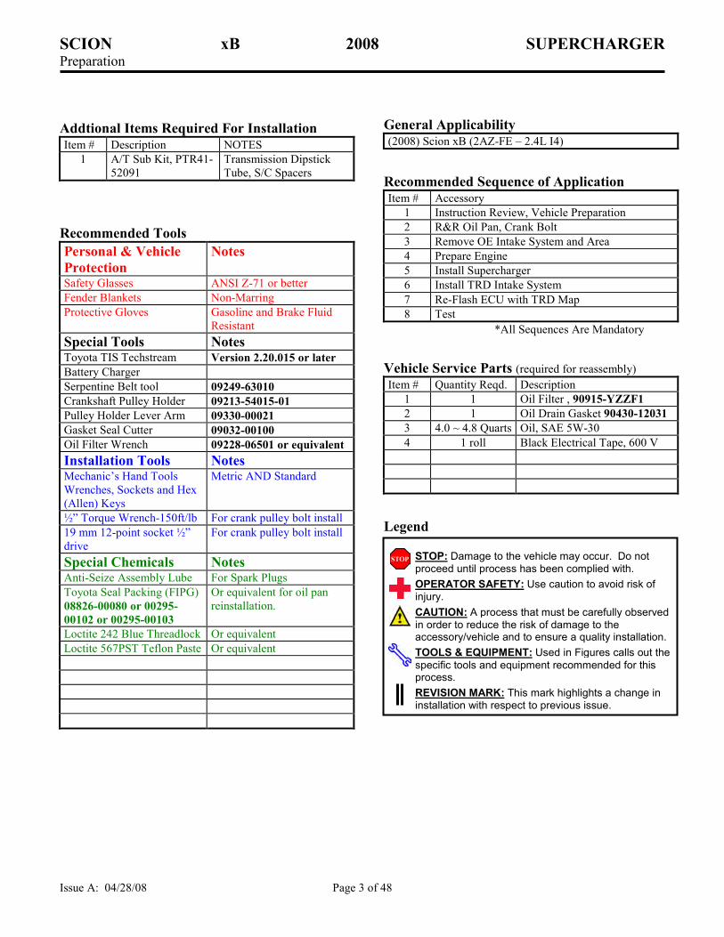
Addtional Items Required For Installation Item # Description NOTES
1 A/T Sub Kit, PTR41-
52091
Transmission Dipstick
Tube, S/C Spacers
Recommended Tools
Personal & Vehicle
Protection
Notes
Safety Glasses ANSI Z-71 or better
Fender Blankets Non-Marring
Protective Gloves Gasoline and Brake Fluid
Resistant
Special Tools Notes Toyota TIS Techstream Version 2.20.015 or later
Battery Charger
Serpentine Belt tool 09249-63010
Crankshaft Pulley Holder 09213-54015-01
Pulley Holder Lever Arm 09330-00021
Gasket Seal Cutter 09032-00100
Oil Filter Wrench 09228-06501 or equivalent
Installation Tools Notes Mechanic’s Hand Tools
Wrenches, Sockets and Hex
(Allen) Keys
Metric AND Standard
½” Torque Wrench-150ft/lb For crank pulley bolt install
19 mm 12-point socket ½”
drive
For crank pulley bolt install
Special Chemicals Notes Anti-Seize Assembly Lube For Spark Plugs
Toyota Seal Packing (FIPG)
08826-00080 or 00295-
00102 or 00295-00103
Or equivalent for oil pan
reinstallation.
Loctite 242 Blue Threadlock Or equivalent
Loctite 567PST Teflon Paste Or equivalent
General Applicability (2008) Scion xB (2AZ-FE – 2.4L I4)
Recommended Sequence of Application Item # Accessory
1 Instruction Review, Vehicle Preparation
2 R&R Oil Pan, Crank Bolt
3 Remove OE Intake System and Area
4 Prepare Engine
5 Install Supercharger
6 Install TRD Intake System
7 Re-Flash ECU with TRD Map
8 Test
*All Sequences Are Mandatory
Vehicle Service Parts (required for reassembly) Item # Quantity Reqd. Description
1 1 Oil Filter , 90915-YZZF1
2 1 Oil Drain Gasket 90430-12031
3 4.0 ~ 4.8 Quarts Oil, SAE 5W-30
4 1 roll Black Electrical Tape, 600 V
Legend
STOP: Damage to the vehicle may occur. Do not
proceed until process has been complied with.
OPERATOR SAFETY: Use caution to avoid risk of
injury.
CAUTION: A process that must be carefully observed
in order to reduce the risk of damage to the accessory/vehicle and to ensure a quality installation.
TOOLS & EQUIPMENT: Used in Figures calls out the
specific tools and equipment recommended for this process.
REVISION MARK: This mark highlights a change in
installation with respect to previous issue.
SCION xB 2008 SUPERCHARGER Preparation
Issue A: 04/28/08 Page 4 of 48
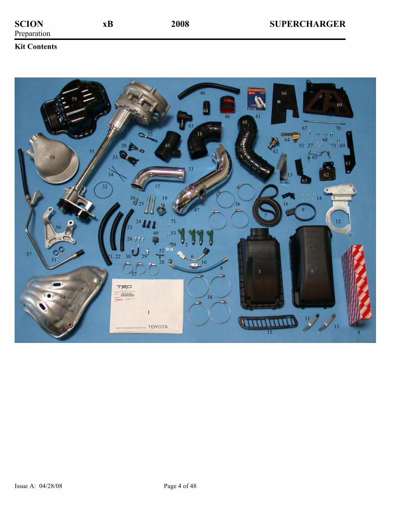
Kit Contents
2
1
4
5
3
51
7
71
50
12
13
14
15
16
17
18
30
19
20
24 23
21, 22
11
11
60 59
33
32
40
41
48
45
26
31
27
25
34
28
35
37
10
38
39
42
46
47 9
53
52
8
54
55
56
7
58
6
49
33 35
36
44
43
61
62 63
64
65
66
67
68 69
70
71
57 29
SCION xB 2008 VEHICLE PREPARATION Procedure
Issue A: 04/28/08 Page 5 of 48
Care must be taken when installing this accessory to ensure damage does not occur to the vehicle. The installation of this
accessory should follow approved guidelines to ensure a quality installation.
These guidelines can be found in the "Accessory Installation Practices" document.
This document covers such items as:-
• Vehicle Protection (use of covers and blankets, cleaning chemicals, etc.).
• Safety (eye protection, rechecking torque procedure, etc.).
• Vehicle Disassembly/Reassembly (panel removal, part storage, etc.).
• Electrical Component Disassembly/Reassembly (battery disconnection, connector removal, etc.).
Please see your Toyota dealer for a copy of this document.
1. Installation review and vehicle preparation.
(a) Review entire installation instructions provided
with this supercharger kit before beginning the
installation.
(b) Review parts list/kit contents to ensure that all
parts are present before beginning the
installation. If any items are missing contact
Technical Support at (800) 688-5912 before
proceeding.
(c) Remove any low-octane fuel from vehicle.
Ensure that ONLY Premium Unleaded
Gasoline 91 Octane or higher is used.
(Octane Method (R+M)/2). Use EXTREME
CAUTION if draining is necessary.
(d) Place vehicle onto vehicle hoist. Place fender
protection blankets over fenders and front of
vehicle to protect cosmetics of vehicle.
(e) Disconnect Negative Battery Terminal (----).
(10mm wrench) Then disconnect battery
positive terminal. Remove battery hold down
strap. Remove battery and plastic tray from
engine compartment. (Caution: Batteries
contain an acid solution, be sure to wear eye
protection and gloves when handling the
battery. Place battery onto workbench until
replacement later. Do not the place battery on
cement or concrete floors.)
12 mm Wrench
2008 SCION xB OIL PAN REPLACEMENT Procedure
Issue A: 04/28/08 Page 6 of 48
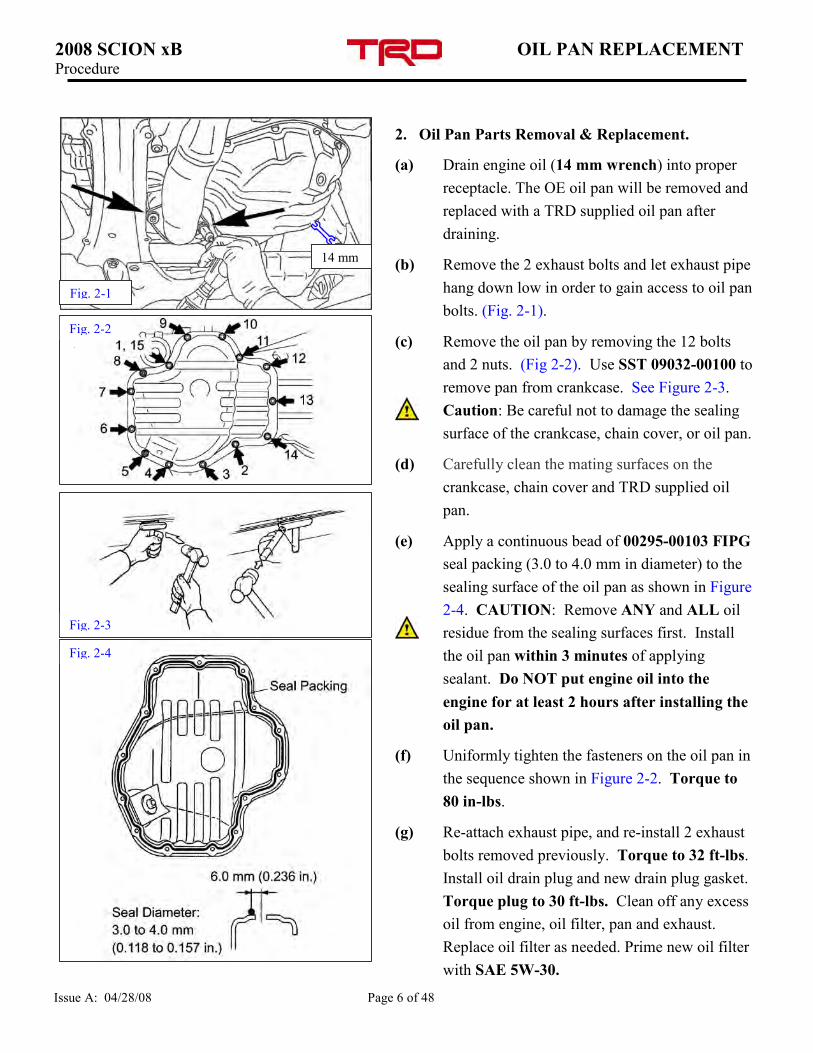
2. Oil Pan Parts Removal & Replacement.
(a) Drain engine oil (14 mm wrench) into proper
receptacle. The OE oil pan will be removed and
replaced with a TRD supplied oil pan after
draining.
(b) Remove the 2 exhaust bolts and let exhaust pipe
hang down low in order to gain access to oil pan
bolts. (Fig. 2-1).
(c) Remove the oil pan by removing the 12 bolts
and 2 nuts. (Fig 2-2). Use SST 09032-00100 to
remove pan from crankcase. See Figure 2-3.
Caution: Be careful not to damage the sealing
surface of the crankcase, chain cover, or oil pan.
(d) Carefully clean the mating surfaces on the
crankcase, chain cover and TRD supplied oil
pan.
(e) Apply a continuous bead of 00295-00103 FIPG
seal packing (3.0 to 4.0 mm in diameter) to the
sealing surface of the oil pan as shown in Figure
2-4. CAUTION: Remove ANY and ALL oil
residue from the sealing surfaces first. Install
the oil pan within 3 minutes of applying
sealant. Do NOT put engine oil into the
engine for at least 2 hours after installing the
oil pan.
(f) Uniformly tighten the fasteners on the oil pan in
the sequence shown in Figure 2-2. Torque to
80 in-lbs.
(g) Re-attach exhaust pipe, and re-install 2 exhaust
bolts removed previously. Torque to 32 ft-lbs.
Install oil drain plug and new drain plug gasket.
Torque plug to 30 ft-lbs. Clean off any excess
oil from engine, oil filter, pan and exhaust.
Replace oil filter as needed. Prime new oil filter
with SAE 5W-30.
Fig. 2-2
Fig. 2-3
Fig. 2-4
Fig. 2-1
14 mm
2008 SCION xB CRANK BOLT REPLACEMENT
& PANEL REMOVAL Procedure
Issue A: 04/28/08 Page 7 of 48
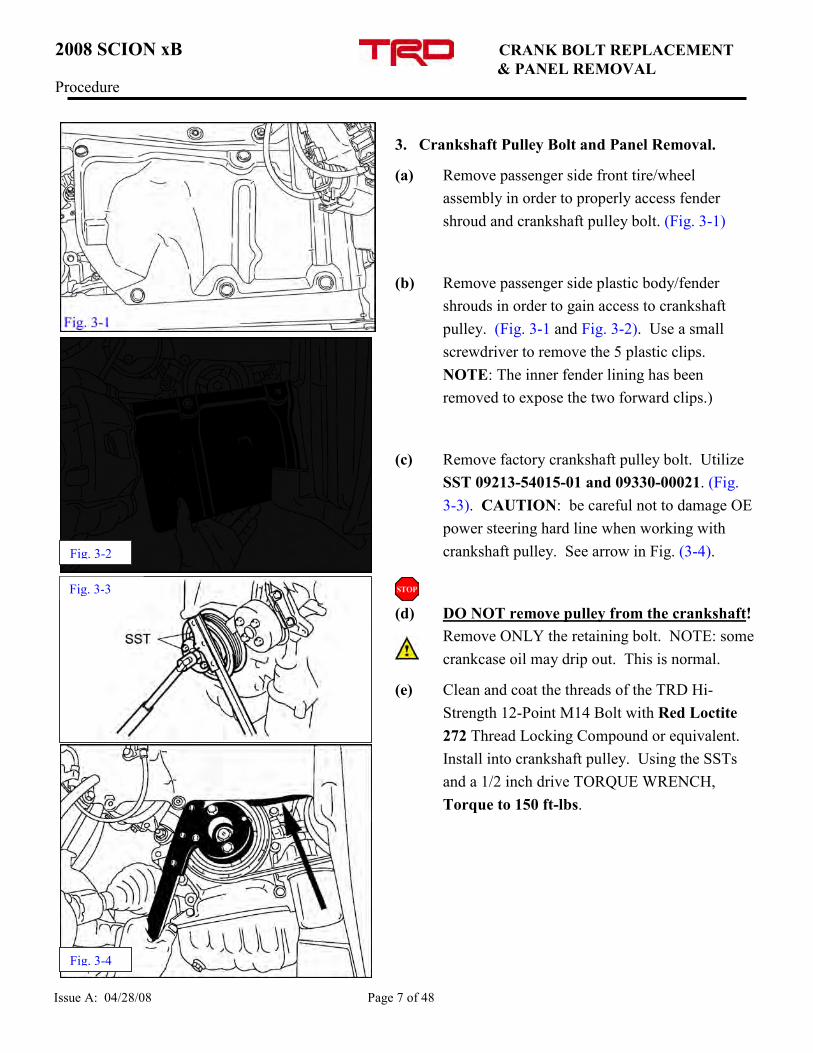
3. Crankshaft Pulley Bolt and Panel Removal.
(a) Remove passenger side front tire/wheel
assembly in order to properly access fender
shroud and crankshaft pulley bolt. (Fig. 3-1)
(b) Remove passenger side plastic body/fender
shrouds in order to gain access to crankshaft
pulley. (Fig. 3-1 and Fig. 3-2). Use a small
screwdriver to remove the 5 plastic clips.
NOTE: The inner fender lining has been
removed to expose the two forward clips.)
(c) Remove factory crankshaft pulley bolt. Utilize
SST 09213-54015-01 and 09330-00021. (Fig.
3-3). CAUTION: be careful not to damage OE
power steering hard line when working with
crankshaft pulley. See arrow in Fig. (3-4).
(d) DO NOT remove pulley from the crankshaft!
Remove ONLY the retaining bolt. NOTE: some
crankcase oil may drip out. This is normal.
(e) Clean and coat the threads of the TRD Hi-
Strength 12-Point M14 Bolt with Red Loctite
272 Thread Locking Compound or equivalent.
Install into crankshaft pulley. Using the SSTs
and a 1/2 inch drive TORQUE WRENCH,
Torque to 150 ft-lbs.
Fig. 3-3
Fig. 3-2
Fig. 3-4
2008 SCION xB CRANK BOLT REPLACEMENT
& PANEL REMOVAL Procedure
Issue A: 04/28/08 Page 8 of 48
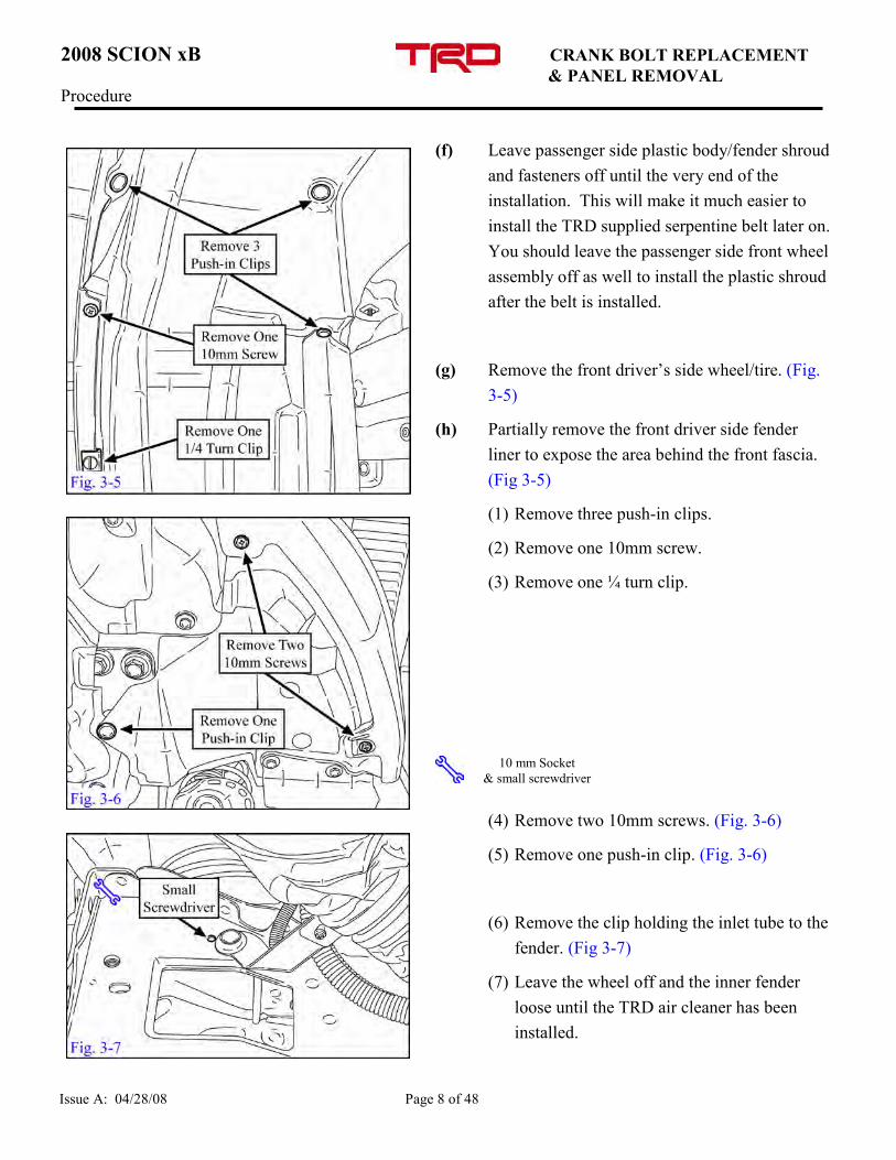
(f) Leave passenger side plastic body/fender shroud
and fasteners off until the very end of the
installation. This will make it much easier to
install the TRD supplied serpentine belt later on.
You should leave the passenger side front wheel
assembly off as well to install the plastic shroud
after the belt is installed.
(g) Remove the front driver’s side wheel/tire. (Fig.
3-5)
(h) Partially remove the front driver side fender
liner to expose the area behind the front fascia.
(Fig 3-5)
(1) Remove three push-in clips.
(2) Remove one 10mm screw.
(3) Remove one ¼ turn clip.
(4) Remove two 10mm screws. (Fig. 3-6)
(5) Remove one push-in clip. (Fig. 3-6)
(6) Remove the clip holding the inlet tube to the
fender. (Fig 3-7)
(7) Leave the wheel off and the inner fender
loose until the TRD air cleaner has been
installed.
10 mm Socket
& small screwdriver FIG. 3-6
2008 SCION xB THERMOSTAT REPLACEMENT Procedure
Issue A: 04/28/08 Page 9 of 48
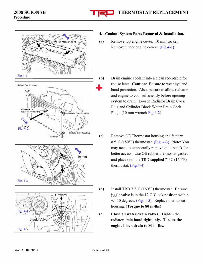
4. Coolant System Parts Removal & Installation.
(a) Remove top engine cover. 10 mm socket.
Remove under engine covers. (Fig.4-1)
(b) Drain engine coolant into a clean receptacle for
re-use later. Caution: Be sure to wear eye and
hand protection. Also, be sure to allow radiator
and engine to cool sufficiently before opening
system to drain. Loosen Radiator Drain Cock
Plug and Cylinder Block Water Drain Cock
Plug. (10 mm wrench-Fig 4-2)
(c) Remove OE Thermostat housing and factory
82° C (180°F) thermostat. (Fig. 4-3). Note: You
may need to temporarily remove oil dipstick for
better access. Use OE rubber thermostat gasket
and place onto the TRD supplied 71°C (160°F)
thermostat. (Fig.4-4)
(d) Install TRD 71° C (160°F) thermostat. Be sure
jiggle valve is in the 12 O’Clock position within
+/- 10 degrees. (Fig. 4-5). Replace thermostat
housing. (Torque to 80 in-lbs)
(e) Close all water drain valves. Tighten the
radiator drain hand tight only. Torque the
engine block drain to 80 in-lbs.
Fig. 4-3
10 mm
Fig. 4-5
Fig. 4-4
10 mm
10 mm socket
Fig 4-1
Fig. 4-2
2008 SCION xB O.E. INTAKE REMOVAL Procedure
Issue A: 04/28/08 Page 10 of 48
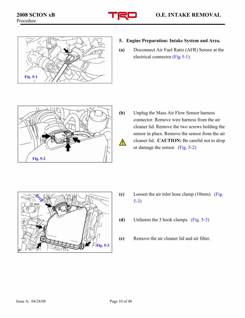
5. Engine Preparation: Intake System and Area.
(a) Disconnect Air Fuel Ratio (AFR) Sensor at the
electrical connector (Fig 5-1).
(b) Unplug the Mass Air Flow Sensor harness
connector. Remove wire harness from the air
cleaner lid. Remove the two screws holding the
sensor in place. Remove the sensor from the air
cleaner lid. CAUTION: Be careful not to drop
or damage the sensor. (Fig. 5-2)
(c) Loosen the air inlet hose clamp (10mm). (Fig.
5-3)
(d) Unfasten the 3 hook clamps. (Fig. 5-3)
(e) Remove the air cleaner lid and air filter.
Fig. 5-1
Phillips
Screwdriver
10 mm
Fig. 5-2
Fig. 5-3
2008 SCION xB O.E. INTAKE REMOVAL Procedure
Issue A: 04/28/08 Page 11 of 48
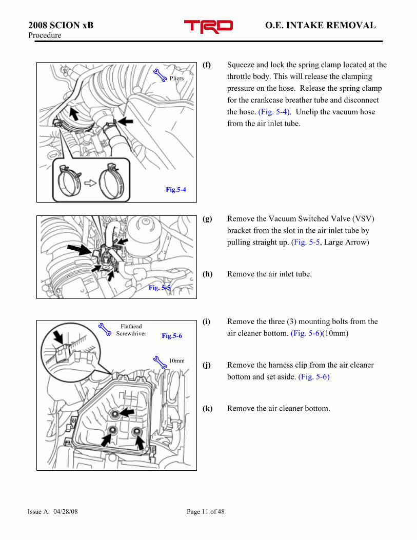
(f) Squeeze and lock the spring clamp located at the
throttle body. This will release the clamping
pressure on the hose. Release the spring clamp
for the crankcase breather tube and disconnect
the hose. (Fig. 5-4). Unclip the vacuum hose
from the air inlet tube.
(g) Remove the Vacuum Switched Valve (VSV)
bracket from the slot in the air inlet tube by
pulling straight up. (Fig. 5-5, Large Arrow)
(h) Remove the air inlet tube.
(i) Remove the three (3) mounting bolts from the
air cleaner bottom. (Fig. 5-6)(10mm)
(j) Remove the harness clip from the air cleaner
bottom and set aside. (Fig. 5-6)
(k) Remove the air cleaner bottom.
Flathead
Screwdriver
10mm
Pliers
Fig.5-6
Fig.5-4
Fig. 5-5
2008 SCION xB O.E. INTAKE REMOVAL Procedure
Issue A: 04/28/08 Page 12 of 48
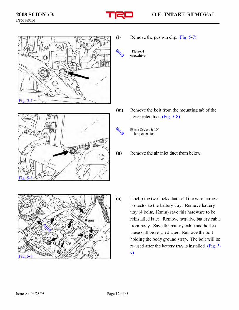
(l) Remove the push-in clip. (Fig. 5-7)
(m) Remove the bolt from the mounting tab of the
lower inlet duct. (Fig. 5-8)
(n) Remove the air inlet duct from below.
(o) Unclip the two locks that hold the wire harness
protector to the battery tray. Remove battery
tray (4 bolts, 12mm) save this hardware to be
reinstalled later. Remove negative battery cable
from body. Save the battery cable and bolt as
these will be re-used later. Remove the bolt
holding the body ground strap. The bolt will be
re-used after the battery tray is installed. (Fig. 5-
9)
10 mm Socket & 10”
long extension
Flathead
Screwdriver
2008 SCION xB ELECTRICAL Procedure
Issue A: 04/28/08 Page 13 of 48
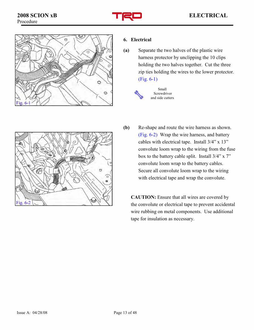
6. Electrical
(a) Separate the two halves of the plastic wire
harness protector by unclipping the 10 clips
holding the two halves together. Cut the three
zip ties holding the wires to the lower protector.
(Fig. 6-1)
(b) Re-shape and route the wire harness as shown.
(Fig. 6-2) Wrap the wire harness, and battery
cables with electrical tape. Install 3/4” x 13”
convolute loom wrap to the wiring from the fuse
box to the battery cable split. Install 3/4” x 7”
convolute loom wrap to the battery cables.
Secure all convolute loom wrap to the wiring
with electrical tape and wrap the convolute.
CAUTION: Ensure that all wires are covered by
the convolute or electrical tape to prevent accidental
wire rubbing on metal components. Use additional
tape for insulation as necessary.
Small
Screwdriver
and side cutters
2008 SCION xB STARTER REMOVAL Procedure
Issue A: 04/28/08 Page 14 of 48
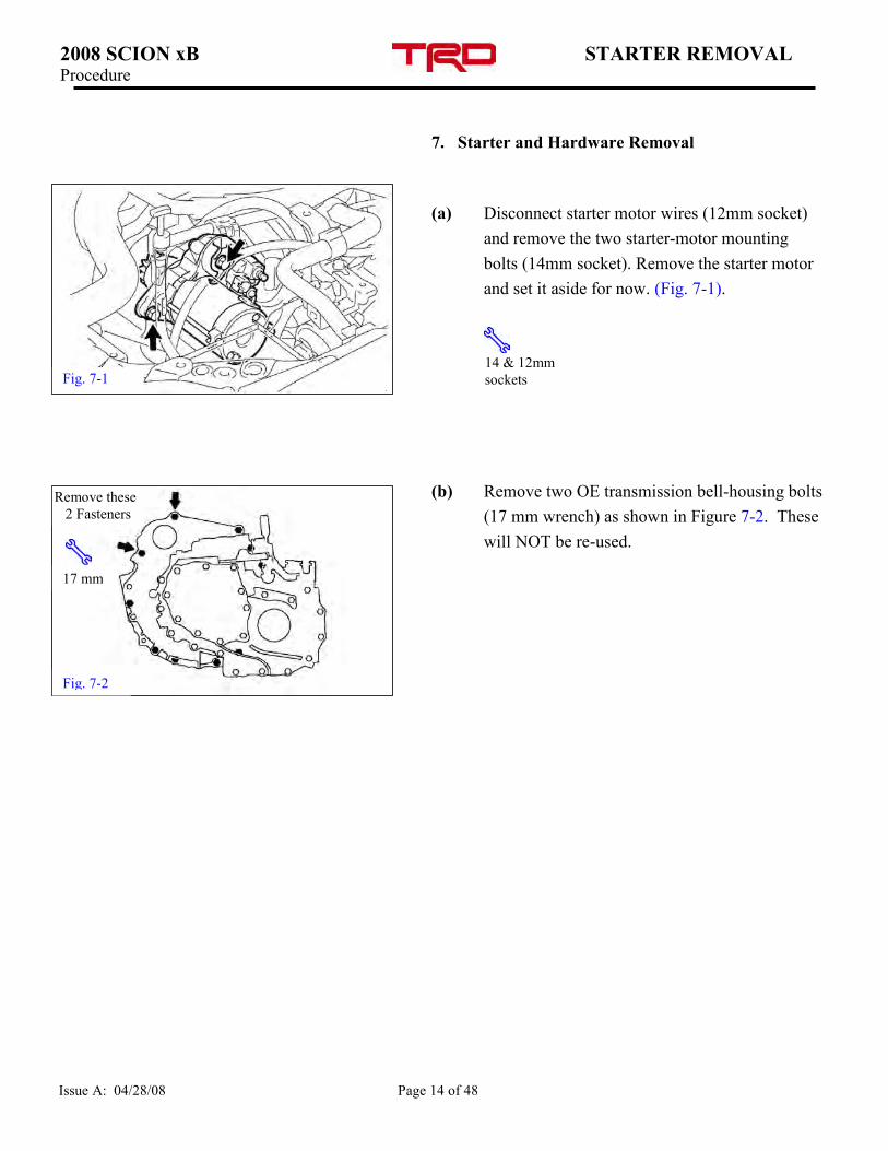
7. Starter and Hardware Removal
(a) Disconnect starter motor wires (12mm socket)
and remove the two starter-motor mounting
bolts (14mm socket). Remove the starter motor
and set it aside for now. (Fig. 7-1).
(b) Remove two OE transmission bell-housing bolts
(17 mm wrench) as shown in Figure 7-2. These
will NOT be re-used.
Fig. 7-1 14 & 12mm
sockets
Fig. 7-2
Remove these
2 Fasteners
17 mm
2008 SCION xB OIL PRESSURE ADAPTER Procedure
Issue A: 04/28/08 Page 15 of 48
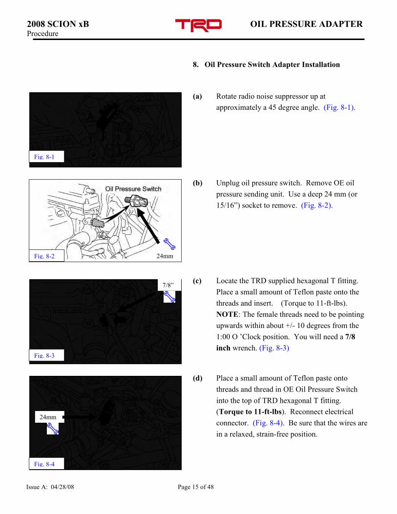
8. Oil Pressure Switch Adapter Installation
(a) Rotate radio noise suppressor up at
approximately a 45 degree angle. (Fig. 8-1).
(b) Unplug oil pressure switch. Remove OE oil
pressure sending unit. Use a deep 24 mm (or
15/16”) socket to remove. (Fig. 8-2).
(c) Locate the TRD supplied hexagonal T fitting.
Place a small amount of Teflon paste onto the
threads and insert. (Torque to 11-ft-lbs).
NOTE: The female threads need to be pointing
upwards within about +/- 10 degrees from the
1:00 O ’Clock position. You will need a 7/8
inch wrench. (Fig. 8-3)
(d) Place a small amount of Teflon paste onto
threads and thread in OE Oil Pressure Switch
into the top of TRD hexagonal T fitting.
(Torque to 11-ft-lbs). Reconnect electrical
connector. (Fig. 8-4). Be sure that the wires are
in a relaxed, strain-free position.
Fig. 8-1
7/8”
Fig. 8-3
Fig. 8-4
24mm
Fig. 8-2 24mm
2008 SCION xB OIL PRESSURE ADAPTER Procedure
Issue A: 04/28/08 Page 16 of 48
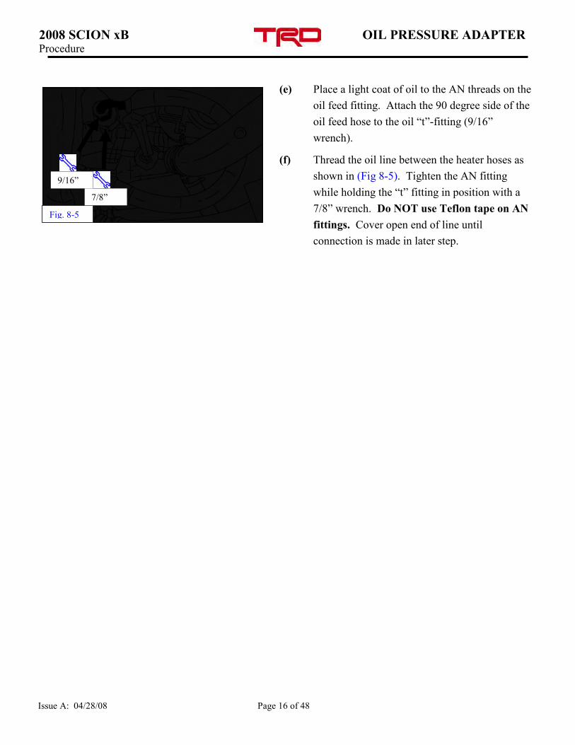
(e) Place a light coat of oil to the AN threads on the
oil feed fitting. Attach the 90 degree side of the
oil feed hose to the oil “t”-fitting (9/16”
wrench).
(f) Thread the oil line between the heater hoses as
shown in (Fig 8-5). Tighten the AN fitting
while holding the “t” fitting in position with a
7/8” wrench. Do NOT use Teflon tape on AN
fittings. Cover open end of line until
connection is made in later step.
Fig. 8-5
9/16”
7/8”
2008 SCION xB ENGINE PREP. DRIVE BELT SIDE Procedure
Issue A: 04/28/08 Page 17 of 48
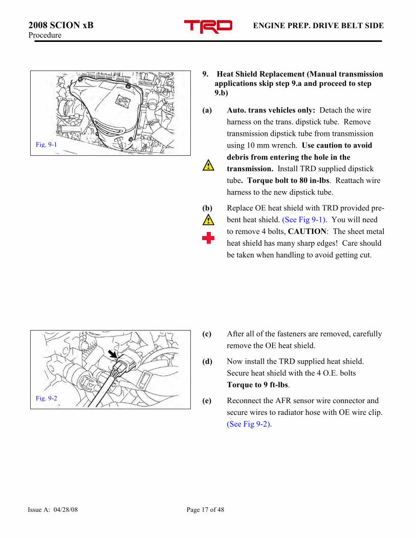
9. Heat Shield Replacement (Manual transmission
applications skip step 9.a and proceed to step
9.b)
(a) Auto. trans vehicles only: Detach the wire
harness on the trans. dipstick tube. Remove
transmission dipstick tube from transmission
using 10 mm wrench. Use caution to avoid
debris from entering the hole in the
transmission. Install TRD supplied dipstick
tube. Torque bolt to 80 in-lbs. Reattach wire
harness to the new dipstick tube.
(b) Replace OE heat shield with TRD provided pre-
bent heat shield. (See Fig 9-1). You will need
to remove 4 bolts, CAUTION: The sheet metal
heat shield has many sharp edges! Care should
be taken when handling to avoid getting cut.
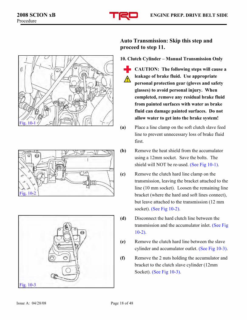
(c) After all of the fasteners are removed, carefully
remove the OE heat shield.
(d) Now install the TRD supplied heat shield.
Secure heat shield with the 4 O.E. bolts
Torque to 9 ft-lbs.
(e) Reconnect the AFR sensor wire connector and
secure wires to radiator hose with OE wire clip.
(See Fig 9-2).
Fig. 9-1
Fig. 9-2
2008 SCION xB ENGINE PREP. DRIVE BELT SIDE Procedure
Issue A: 04/28/08 Page 18 of 48
Auto Transmission: Skip this step and
proceed to step 11.
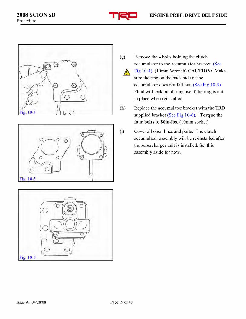
10. Clutch Cylinder – Manual Transmission Only
CAUTION: The following steps will cause a
leakage of brake fluid. Use appropriate
personal protection gear (gloves and safety
glasses) to avoid personal injury. When
completed, remove any residual brake fluid
from painted surfaces with water as brake
fluid can damage painted surfaces. Do not
allow water to get into the brake system!
(a) Place a line clamp on the soft clutch slave feed
line to prevent unnecessary loss of brake fluid
first.
(b) Remove the heat shield from the accumulator
using a 12mm socket. Save the bolts. The
shield will NOT be re-used. (See Fig 10-1).
(c) Remove the clutch hard line clamp on the
transmission, leaving the bracket attached to the
line (10 mm socket). Loosen the remaining line
bracket (where the hard and soft lines connect),
but leave attached to the transmission (12 mm
socket). (See Fig 10-2).
(d) Disconnect the hard clutch line between the
transmission and the accumulator inlet. (See Fig
10-2).
(e) Remove the clutch hard line between the slave
cylinder and accumulator outlet. (See Fig 10-3).
(f) Remove the 2 nuts holding the accumulator and
bracket to the clutch slave cylinder (12mm
Socket). (See Fig 10-3).
FIG. 7-1
2008 SCION xB ENGINE PREP. DRIVE BELT SIDE Procedure
Issue A: 04/28/08 Page 19 of 48
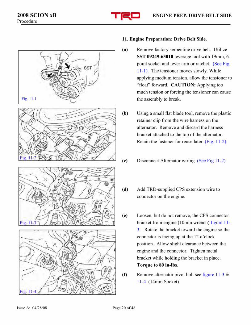
(g) Remove the 4 bolts holding the clutch
accumulator to the accumulator bracket. (See
Fig 10-4). (10mm Wrench) CAUTION: Make
sure the ring on the back side of the
accumulator does not fall out. (See Fig 10-5).
Fluid will leak out during use if the ring is not
in place when reinstalled.
(h) Replace the accumulator bracket with the TRD
supplied bracket (See Fig 10-6). Torque the
four bolts to 80in-lbs. (10mm socket)
(i) Cover all open lines and ports. The clutch
accumulator assembly will be re-installed after
the supercharger unit is installed. Set this
assembly aside for now.
2008 SCION xB ENGINE PREP. DRIVE BELT SIDE Procedure
Issue A: 04/28/08 Page 20 of 48
11. Engine Preparation: Drive Belt Side.
(a) Remove factory serpentine drive belt. Utilize
SST 09249-63010 leverage tool with 19mm, 6-
point socket and lever arm or ratchet. (See Fig
11-1). The tensioner moves slowly. While
applying medium tension, allow the tensioner to
“float” forward. CAUTION: Applying too
much tension or forcing the tensioner can cause
the assembly to break.
(b) Using a small flat blade tool, remove the plastic
retainer clip from the wire harness on the
alternator. Remove and discard the harness
bracket attached to the top of the alternator.
Retain the fastener for reuse later. (Fig. 11-2).
(c) Disconnect Alternator wiring. (See Fig 11-2).
(d) Add TRD-supplied CPS extension wire to
connector on the engine.
(e) Loosen, but do not remove, the CPS connector
bracket from engine (10mm wrench) figure 11-
3. Rotate the bracket toward the engine so the
connector is facing up at the 12 o’clock
position. Allow slight clearance between the
engine and the connector. Tighten metal
bracket while holding the bracket in place.
Torque to 80 in-lbs.
(f) Remove alternator pivot bolt see figure 11-3.&
11-4 (14mm Socket).
Fig. 11-1
Fig. 11-2
2008 SCION xB FUEL INJECTOR REPLACEMENT Procedure
Issue A: 04/28/08 Page 21 of 48
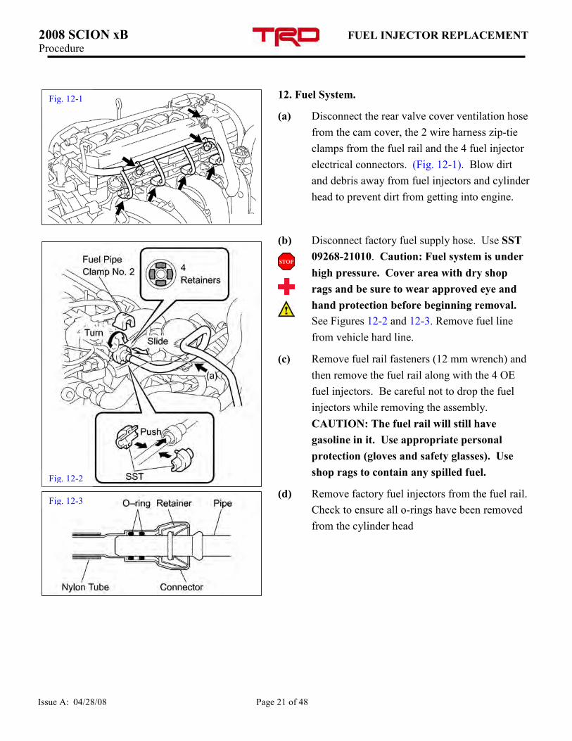
12. Fuel System.
(a) Disconnect the rear valve cover ventilation hose
from the cam cover, the 2 wire harness zip-tie
clamps from the fuel rail and the 4 fuel injector
electrical connectors. (Fig. 12-1). Blow dirt
and debris away from fuel injectors and cylinder
head to prevent dirt from getting into engine.
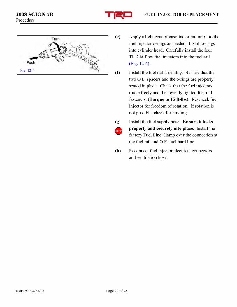
(b) Disconnect factory fuel supply hose. Use SST
09268-21010. Caution: Fuel system is under
high pressure. Cover area with dry shop
rags and be sure to wear approved eye and
hand protection before beginning removal.
See Figures 12-2 and 12-3. Remove fuel line
from vehicle hard line.
(c) Remove fuel rail fasteners (12 mm wrench) and
then remove the fuel rail along with the 4 OE
fuel injectors. Be careful not to drop the fuel
injectors while removing the assembly.
CAUTION: The fuel rail will still have
gasoline in it. Use appropriate personal
protection (gloves and safety glasses). Use
shop rags to contain any spilled fuel.
(d) Remove factory fuel injectors from the fuel rail.
Check to ensure all o-rings have been removed
from the cylinder head
Fig. 12-3
Fig. 12-2
Fig. 12-1
2008 SCION xB FUEL INJECTOR REPLACEMENT Procedure
Issue A: 04/28/08 Page 22 of 48
(e) Apply a light coat of gasoline or motor oil to the
fuel injector o-rings as needed. Install o-rings
into cylinder head. Carefully install the four
TRD hi-flow fuel injectors into the fuel rail.
(Fig. 12-4).
(f) Install the fuel rail assembly. Be sure that the
two O.E. spacers and the o-rings are properly
seated in place. Check that the fuel injectors
rotate freely and then evenly tighten fuel rail
fasteners. (Torque to 15 ft-lbs). Re-check fuel
injector for freedom of rotation. If rotation is
not possible, check for binding.
(g) Install the fuel supply hose. Be sure it locks
properly and securely into place. Install the
factory Fuel Line Clamp over the connection at
the fuel rail and O.E. fuel hard line.
(h) Reconnect fuel injector electrical connectors
and ventilation hose.
Fig. 12-4
2008 SCION xB SPARK PLUG REPLACEMENT Procedure
Issue A: 04/28/08 Page 23 of 48
13. Spark Plug Replacement.
(a) Unplug ignition coil connectors and remove the
ignition coils. (10 mm socket). (Fig. 13-1).
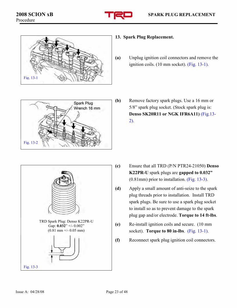
(b) Remove factory spark plugs. Use a 16 mm or
5/8” spark plug socket. (Stock spark plug is:
Denso SK20R11 or NGK IFR6A11) (Fig.13-
2).
(c) Ensure that all TRD (P/N PTR24-21050) Denso
K22PR-U spark plugs are gapped to 0.032”
(0.81mm) prior to installation. (Fig. 13-3).
(d) Apply a small amount of anti-seize to the spark
plug threads prior to installation. Install TRD
spark plugs. Be sure to use a spark plug socket
to install so as to prevent damage to the spark
plug gap and/or electrode. Torque to 14 ft-lbs.
(e) Re-install ignition coils and secure. (10 mm
socket). Torque to 80 in-lbs. (Fig. 13-1).
(f) Reconnect spark plug ignition coil connectors.
Fig. 13-1
Fig. 13-3
TRD Spark Plug: Denso K22PR-U
Gap: 0.032” +/- 0.002”
(0.81 mm +/- 0.05 mm)
Fig. 13-2
2008 SCION xB SUPERCHARGER INSTALLATION Procedure
Issue A: 04/28/08 Page 24 of 48
14. Supercharger drive / unit installation
(a) Remove supercharger assembly from packaging
and place onto a workbench.
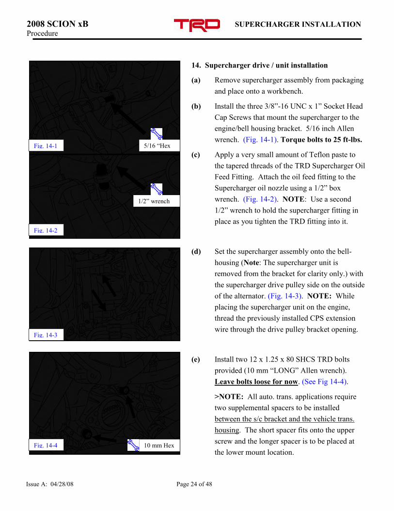
(b) Install the three 3/8”-16 UNC x 1” Socket Head
Cap Screws that mount the supercharger to the
engine/bell housing bracket. 5/16 inch Allen
wrench. (Fig. 14-1). Torque bolts to 25 ft-lbs.
(c) Apply a very small amount of Teflon paste to
the tapered threads of the TRD Supercharger Oil
Feed Fitting. Attach the oil feed fitting to the
Supercharger oil nozzle using a 1/2” box
wrench. (Fig. 14-2). NOTE: Use a second
1/2” wrench to hold the supercharger fitting in
place as you tighten the TRD fitting into it.
(d) Set the supercharger assembly onto the bell-
housing (Note: The supercharger unit is
removed from the bracket for clarity only.) with
the supercharger drive pulley side on the outside
of the alternator. (Fig. 14-3). NOTE: While
placing the supercharger unit on the engine,
thread the previously installed CPS extension
wire through the drive pulley bracket opening.
(e) Install two 12 x 1.25 x 80 SHCS TRD bolts
provided (10 mm “LONG” Allen wrench).
Leave bolts loose for now. (See Fig 14-4).
>NOTE: All auto. trans. applications require
two supplemental spacers to be installed
between the s/c bracket and the vehicle trans.
housing. The short spacer fits onto the upper
screw and the longer spacer is to be placed at
the lower mount location.
Fig. 14-3
5/16 “Hex Fig. 14-1
1/2” wrench
Fig. 14-2
Fig. 14-4 10 mm Hex
2008 SCION xB SUPERCHARGER INSTALLATION Procedure
Issue A: 04/28/08 Page 25 of 48
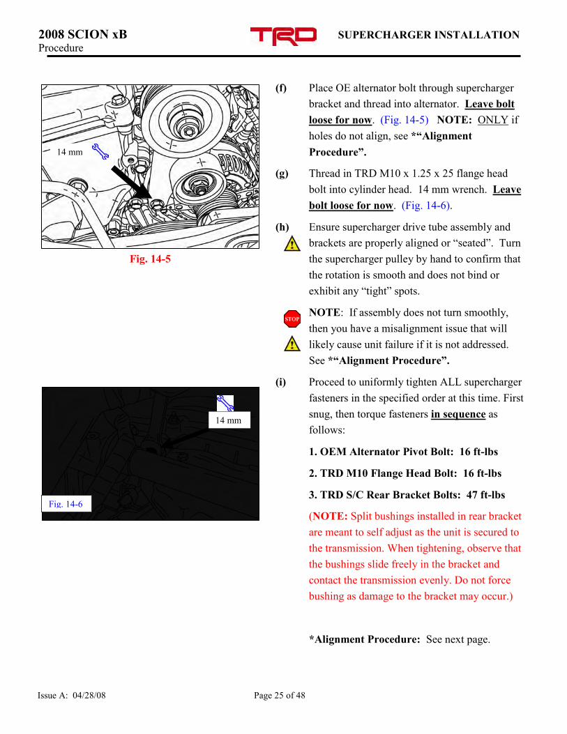
(f) Place OE alternator bolt through supercharger
bracket and thread into alternator. Leave bolt
loose for now. (Fig. 14-5) NOTE: ONLY if
holes do not align, see *“Alignment
Procedure”.
(g) Thread in TRD M10 x 1.25 x 25 flange head
bolt into cylinder head. 14 mm wrench. Leave
bolt loose for now. (Fig. 14-6).
(h) Ensure supercharger drive tube assembly and
brackets are properly aligned or “seated”. Turn
the supercharger pulley by hand to confirm that
the rotation is smooth and does not bind or
exhibit any “tight” spots.
NOTE: If assembly does not turn smoothly,
then you have a misalignment issue that will
likely cause unit failure if it is not addressed.
See *“Alignment Procedure”.
(i) Proceed to uniformly tighten ALL supercharger
fasteners in the specified order at this time. First
snug, then torque fasteners in sequence as
follows:
1. OEM Alternator Pivot Bolt: 16 ft-lbs
2. TRD M10 Flange Head Bolt: 16 ft-lbs
3. TRD S/C Rear Bracket Bolts: 47 ft-lbs
(NOTE: Split bushings installed in rear bracket
are meant to self adjust as the unit is secured to
the transmission. When tightening, observe that
the bushings slide freely in the bracket and
contact the transmission evenly. Do not force
bushing as damage to the bracket may occur.)
*Alignment Procedure: See next page.
14 mm
14 mm
Fig. 14-6
Fig. 14-5
2008 SCION xB SUPERCHARGER INSTALLATION Procedure
Issue A: 04/28/08 Page 26 of 48
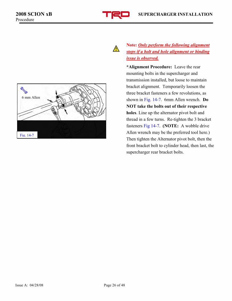
Note: Only perform the following alignment
steps if a bolt and hole alignment or binding
issue is observed.
*Alignment Procedure: Leave the rear
mounting bolts in the supercharger and
transmission installed, but loose to maintain
bracket alignment. Temporarily loosen the
three bracket fasteners a few revolutions, as
shown in Fig. 14-7. 6mm Allen wrench. Do
NOT take the bolts out of their respective
holes. Line up the alternator pivot bolt and
thread in a few turns. Re-tighten the 3 bracket
fasteners Fig 14-7. (NOTE: A wobble drive
Allen wrench may be the preferred tool here.)
Then tighten the Alternator pivot bolt, then the
front bracket bolt to cylinder head, then last, the
supercharger rear bracket bolts.
Fig. 14-7
6 mm Allen
2008 SCION xB CLUTCH CYLINDER RE-ASSEMBLY Procedure
Issue A: 04/28/08 Page 27 of 48
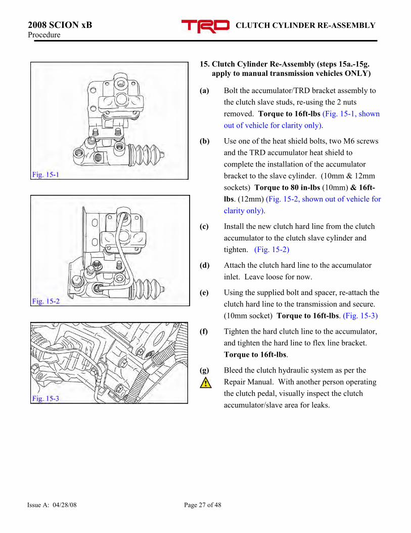
15. Clutch Cylinder Re-Assembly (steps 15a.-15g.
apply to manual transmission vehicles ONLY)
(a) Bolt the accumulator/TRD bracket assembly to
the clutch slave studs, re-using the 2 nuts
removed. Torque to 16ft-lbs (Fig. 15-1, shown
out of vehicle for clarity only).
(b) Use one of the heat shield bolts, two M6 screws
and the TRD accumulator heat shield to
complete the installation of the accumulator
bracket to the slave cylinder. (10mm & 12mm
sockets) Torque to 80 in-lbs (10mm) & 16ft-
lbs. (12mm) (Fig. 15-2, shown out of vehicle for
clarity only).
(c) Install the new clutch hard line from the clutch
accumulator to the clutch slave cylinder and
tighten. (Fig. 15-2)
(d) Attach the clutch hard line to the accumulator
inlet. Leave loose for now.
(e) Using the supplied bolt and spacer, re-attach the
clutch hard line to the transmission and secure.
(10mm socket) Torque to 16ft-lbs. (Fig. 15-3)
(f) Tighten the hard clutch line to the accumulator,
and tighten the hard line to flex line bracket.
Torque to 16ft-lbs.
(g) Bleed the clutch hydraulic system as per the
Repair Manual. With another person operating
the clutch pedal, visually inspect the clutch
accumulator/slave area for leaks.
2008 SCION xB STARTER INSTALLATION Procedure
Issue A: 04/28/08 Page 28 of 48
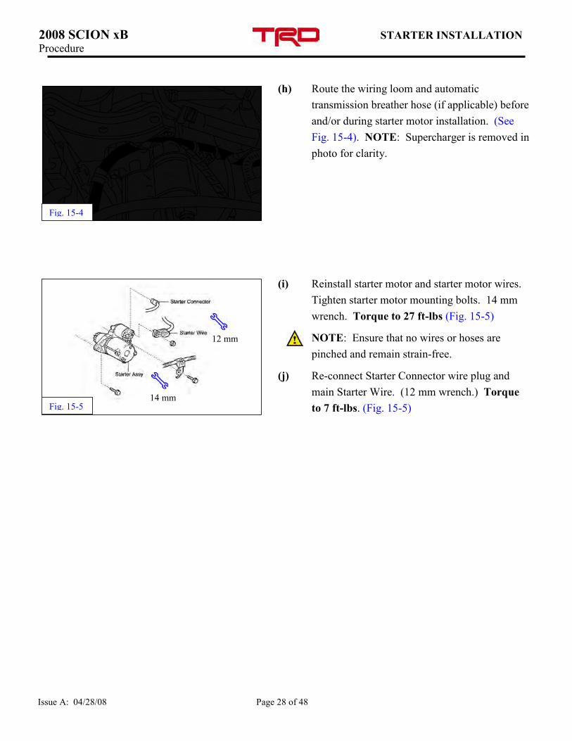
(h) Route the wiring loom and automatic
transmission breather hose (if applicable) before
and/or during starter motor installation. (See
Fig. 15-4). NOTE: Supercharger is removed in
photo for clarity.
(i) Reinstall starter motor and starter motor wires.
Tighten starter motor mounting bolts. 14 mm
wrench. Torque to 27 ft-lbs (Fig. 15-5)
NOTE: Ensure that no wires or hoses are
pinched and remain strain-free.
(j) Re-connect Starter Connector wire plug and
main Starter Wire. (12 mm wrench.) Torque
to 7 ft-lbs. (Fig. 15-5)
Fig. 15-4
12 mm
Fig. 15-5 14 mm
2008 SCION xB OIL FEED CONNECTION Procedure
Issue A: 04/28/08 Page 29 of 48
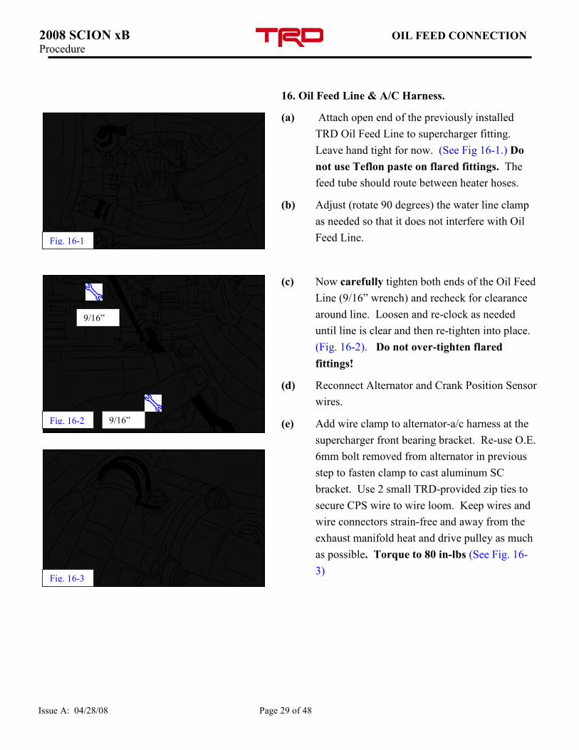
16. Oil Feed Line & A/C Harness.
(a) Attach open end of the previously installed
TRD Oil Feed Line to supercharger fitting.
Leave hand tight for now. (See Fig 16-1.) Do
not use Teflon paste on flared fittings. The
feed tube should route between heater hoses.
(b) Adjust (rotate 90 degrees) the water line clamp
as needed so that it does not interfere with Oil
Feed Line.
(c) Now carefully tighten both ends of the Oil Feed
Line (9/16” wrench) and recheck for clearance
around line. Loosen and re-clock as needed
until line is clear and then re-tighten into place.
(Fig. 16-2). Do not over-tighten flared
fittings!
(d) Reconnect Alternator and Crank Position Sensor
wires.
(e) Add wire clamp to alternator-a/c harness at the
supercharger front bearing bracket. Re-use O.E.
6mm bolt removed from alternator in previous
step to fasten clamp to cast aluminum SC
bracket. Use 2 small TRD-provided zip ties to
secure CPS wire to wire loom. Keep wires and
wire connectors strain-free and away from the
exhaust manifold heat and drive pulley as much
as possible. Torque to 80 in-lbs (See Fig. 16-
3)
9/16”
9/16” Fig. 16-2
Fig. 16-1
Fig. 16-3
2008 SCION xB OIL DRAIN CONNECTION Procedure
Issue A: 04/28/08 Page 30 of 48
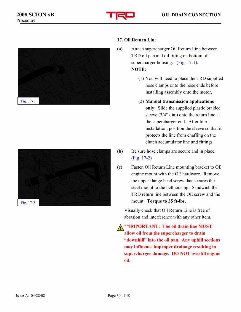
17. Oil Return Line.
(a) Attach supercharger Oil Return Line between
TRD oil pan and oil fitting on bottom of
supercharger housing. (Fig. 17-1).
NOTE:
(1) You will need to place the TRD supplied
hose clamps onto the hose ends before
installing assembly onto the motor.
(2) Manual transmission applications
only: Slide the supplied plastic braided
sleeve (3/4” dia.) onto the return line at
the supercharger end. After line
installation, position the sleeve so that it
protects the line from chaffing on the
clutch accumulator line and fittings.
(b) Be sure hose clamps are secure and in place.
(Fig. 17-2)
(c) Fasten Oil Return Line mounting bracket to OE
engine mount with the OE hardware. Remove
the upper flange head screw that secures the
steel mount to the bellhousing. Sandwich the
TRD return line between the OE screw and the
mount. Torque to 35 ft-lbs.
Visually check that Oil Return Line is free of
abrasion and interference with any other item.
**IMPORTANT: The oil drain line MUST
allow oil from the supercharger to drain
“downhill” into the oil pan. Any uphill sections
may influence improper drainage resulting in
supercharger damage. DO NOT overfill engine
oil.
Fig. 17-1
Fig. 17-2
2008 SCION xB AIR INLET AND DISCHARGE
INSTALLATION Procedure
Issue A: 04/28/08 Page 31 of 48
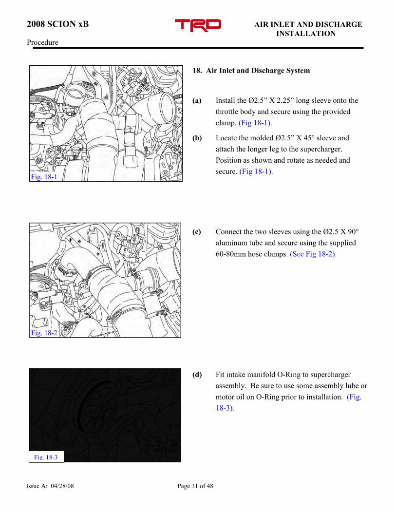
18. Air Inlet and Discharge System
(a) Install the Ø2.5” X 2.25” long sleeve onto the
throttle body and secure using the provided
clamp. (Fig 18-1).
(b) Locate the molded Ø2.5” X 45° sleeve and
attach the longer leg to the supercharger.
Position as shown and rotate as needed and
secure. (Fig 18-1).
(c) Connect the two sleeves using the Ø2.5 X 90°
aluminum tube and secure using the supplied
60-80mm hose clamps. (See Fig 18-2).
(d) Fit intake manifold O-Ring to supercharger
assembly. Be sure to use some assembly lube or
motor oil on O-Ring prior to installation. (Fig.
18-3).
Fig. 18-3
2008 SCION xB AIR INLET AND DISCHARGE
INSTALLATION Procedure
Issue A: 04/28/08 Page 32 of 48
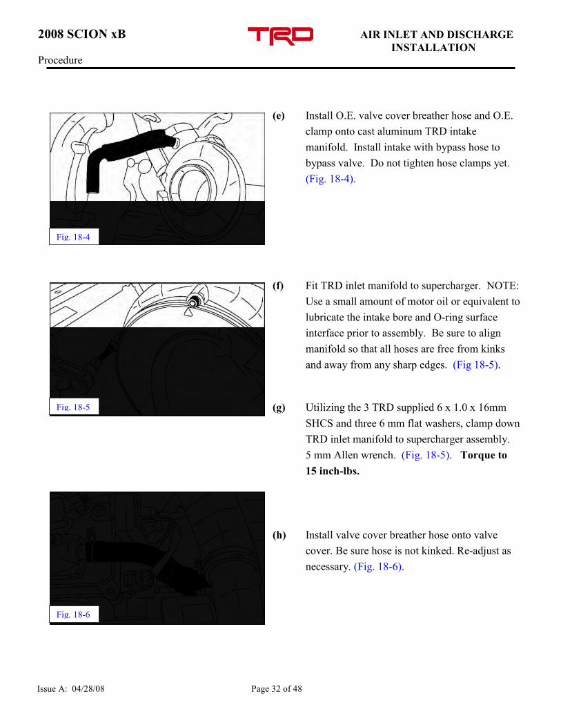
(e) Install O.E. valve cover breather hose and O.E.
clamp onto cast aluminum TRD intake
manifold. Install intake with bypass hose to
bypass valve. Do not tighten hose clamps yet.
(Fig. 18-4).
(f) Fit TRD inlet manifold to supercharger. NOTE:
Use a small amount of motor oil or equivalent to
lubricate the intake bore and O-ring surface
interface prior to assembly. Be sure to align
manifold so that all hoses are free from kinks
and away from any sharp edges. (Fig 18-5).
(g) Utilizing the 3 TRD supplied 6 x 1.0 x 16mm
SHCS and three 6 mm flat washers, clamp down
TRD inlet manifold to supercharger assembly.
5 mm Allen wrench. (Fig. 18-5). Torque to
15 inch-lbs.
(h) Install valve cover breather hose onto valve
cover. Be sure hose is not kinked. Re-adjust as
necessary. (Fig. 18-6).
Fig. 18-6
Fig. 18-4
Fig. 18-5
2008 SCION xB AIR INLET AND DISCHARGE
INSTALLATION Procedure
Issue A: 04/28/08 Page 33 of 48
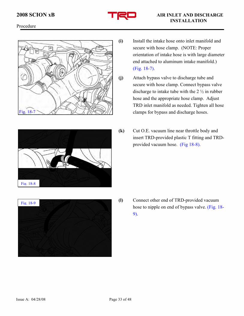
(i) Install the intake hose onto inlet manifold and
secure with hose clamp. (NOTE: Proper
orientation of intake hose is with large diameter
end attached to aluminum intake manifold.)
(Fig. 18-7).
(j) Attach bypass valve to discharge tube and
secure with hose clamp. Connect bypass valve
discharge to intake tube with the 2 ½ in rubber
hose and the appropriate hose clamp. Adjust
TRD inlet manifold as needed. Tighten all hose
clamps for bypass and discharge hoses.
(k) Cut O.E. vacuum line near throttle body and
insert TRD-provided plastic T fitting and TRD-
provided vacuum hose. (Fig 18-8).
(l) Connect other end of TRD-provided vacuum
hose to nipple on end of bypass valve. (Fig. 18-
9).
Fig. 18-9
Fig. 18-8
2008 SCION xB VSV RELOCATION Procedure
Issue A: 04/28/08 Page 34 of 48
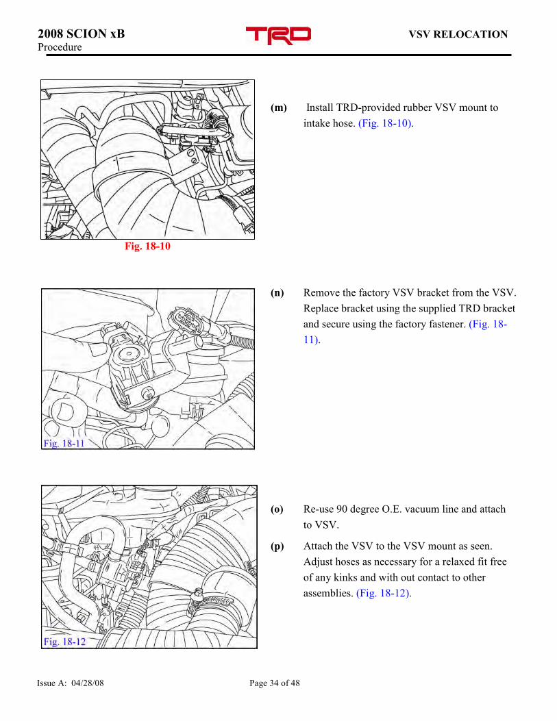
(m) Install TRD-provided rubber VSV mount to
intake hose. (Fig. 18-10).
(n) Remove the factory VSV bracket from the VSV.
Replace bracket using the supplied TRD bracket
and secure using the factory fastener. (Fig. 18-
11).
(o) Re-use 90 degree O.E. vacuum line and attach
to VSV.
(p) Attach the VSV to the VSV mount as seen.
Adjust hoses as necessary for a relaxed fit free
of any kinks and with out contact to other
assemblies. (Fig. 18-12).
Fig. 18-10
2008 SCION xB AIR INLET INSTALLATION Procedure
Issue A: 04/28/08 Page 35 of 48
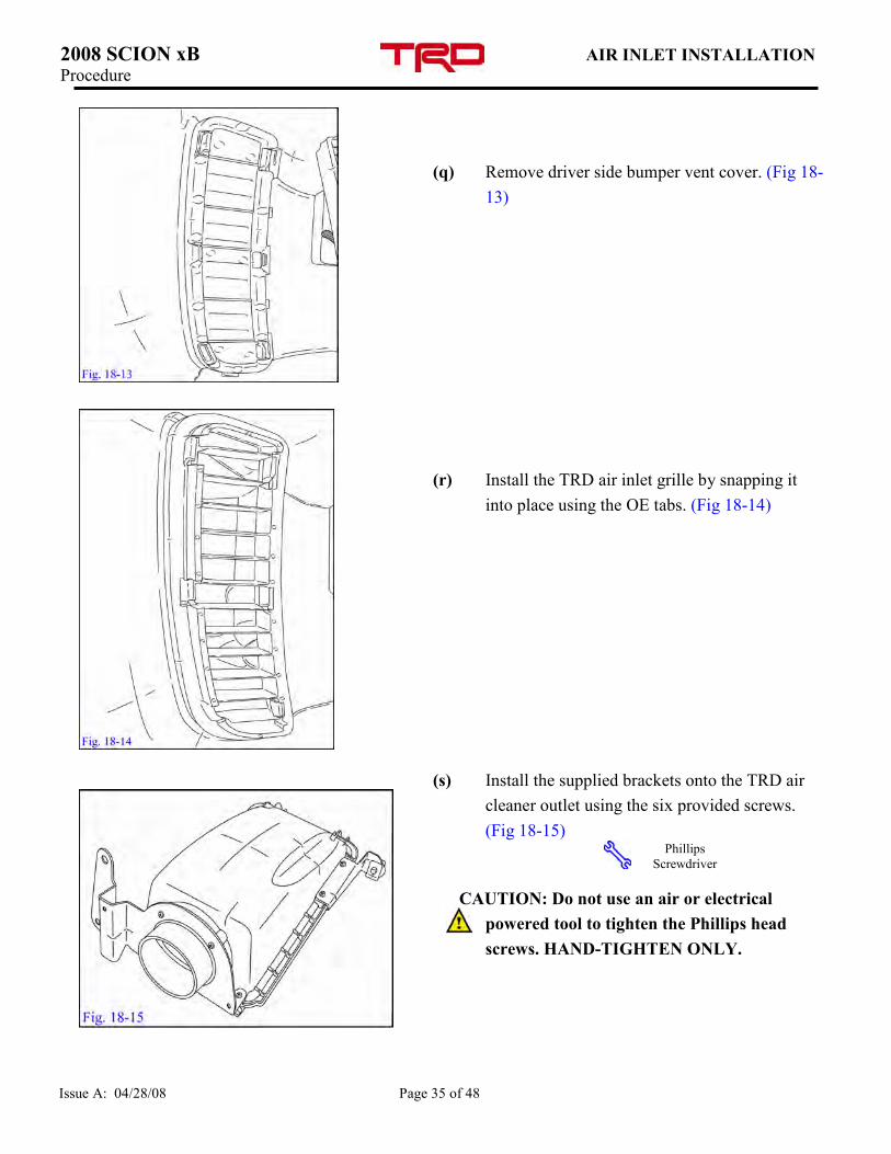
(q) Remove driver side bumper vent cover. (Fig 18-
13)
(r) Install the TRD air inlet grille by snapping it
into place using the OE tabs. (Fig 18-14)
(s) Install the supplied brackets onto the TRD air
cleaner outlet using the six provided screws.
(Fig 18-15)
CAUTION: Do not use an air or electrical
powered tool to tighten the Phillips head
screws. HAND-TIGHTEN ONLY.
Phillips
Screwdriver
2008 SCION xB AIR INLET INSTALLATION Procedure
Issue A: 04/28/08 Page 36 of 48
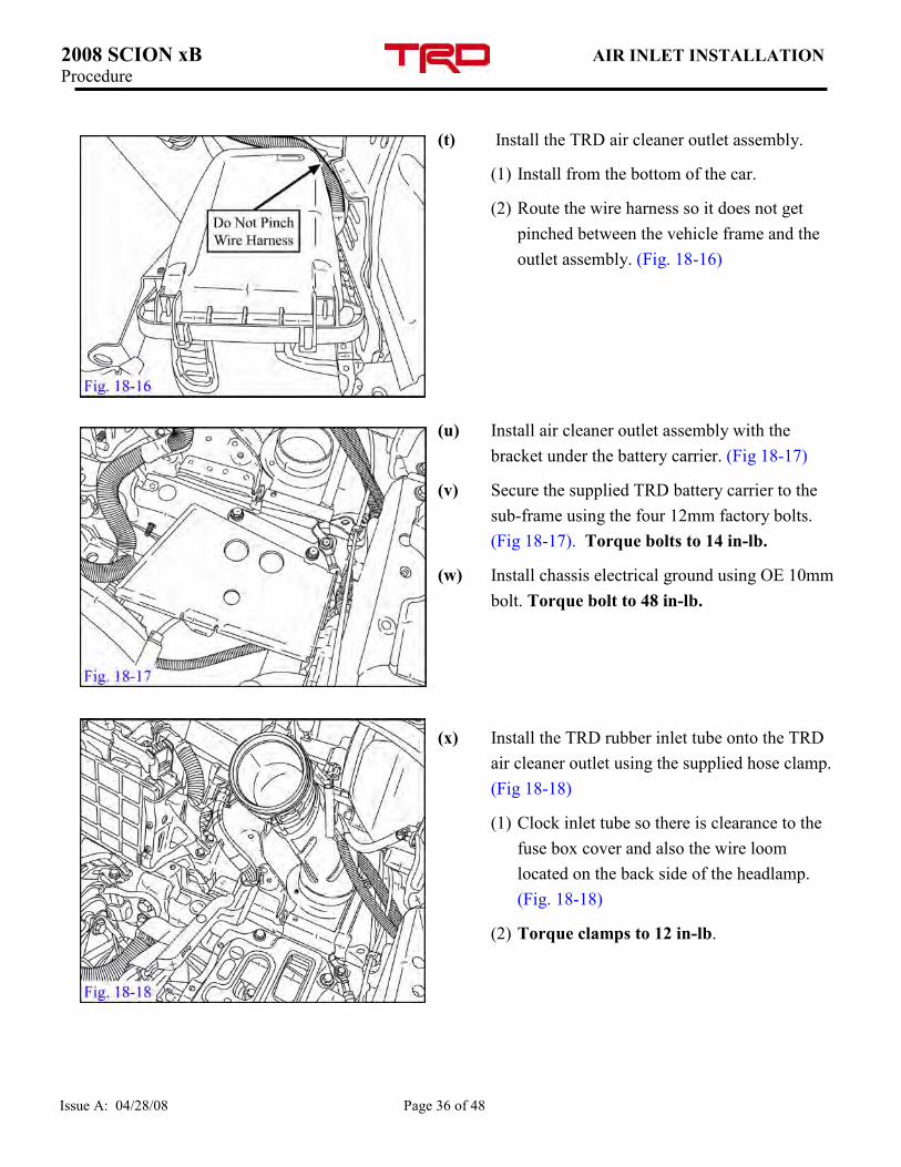
(t) Install the TRD air cleaner outlet assembly.
(1) Install from the bottom of the car.
(2) Route the wire harness so it does not get
pinched between the vehicle frame and the
outlet assembly. (Fig. 18-16)
(u) Install air cleaner outlet assembly with the
bracket under the battery carrier. (Fig 18-17)
(v) Secure the supplied TRD battery carrier to the
sub-frame using the four 12mm factory bolts.
(Fig 18-17). Torque bolts to 14 in-lb.
(w) Install chassis electrical ground using OE 10mm
bolt. Torque bolt to 48 in-lb.
(x) Install the TRD rubber inlet tube onto the TRD
air cleaner outlet using the supplied hose clamp.
(Fig 18-18)
(1) Clock inlet tube so there is clearance to the
fuse box cover and also the wire loom
located on the back side of the headlamp.
(Fig. 18-18)
(2) Torque clamps to 12 in-lb.
2008 SCION xB AIR INLET INSTALLATION Procedure
Issue A: 04/28/08 Page 37 of 48
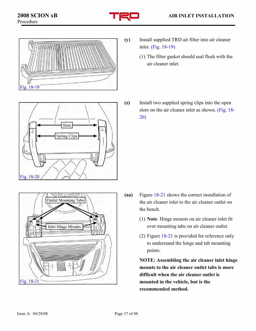
(y) Install supplied TRD air filter into air cleaner
inlet. (Fig. 18-19)
(1) The filter gasket should seal flush with the
air cleaner inlet.
(z) Install two supplied spring clips into the open
slots on the air cleaner inlet as shown. (Fig. 18-
20)
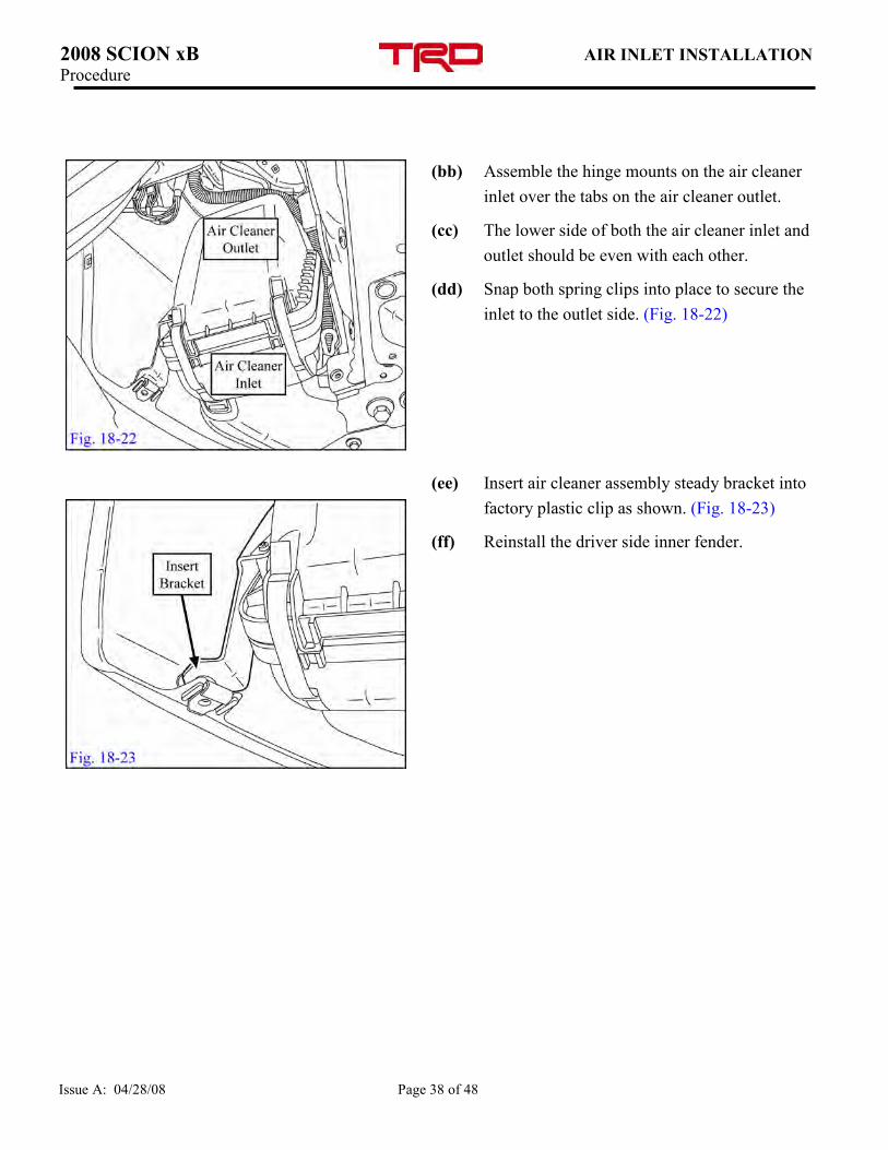
(aa) Figure 18-21 shows the correct installation of
the air cleaner inlet to the air cleaner outlet on
the bench.
(1) Note: Hinge mounts on air cleaner inlet fit
over mounting tabs on air cleaner outlet.
(2) Figure 18-21 is provided for reference only
to understand the hinge and tab mounting
points.
NOTE: Assembling the air cleaner inlet hinge
mounts to the air cleaner outlet tabs is more
difficult when the air cleaner outlet is
mounted in the vehicle, but is the
recommended method.
2008 SCION xB AIR INLET INSTALLATION Procedure
Issue A: 04/28/08 Page 38 of 48
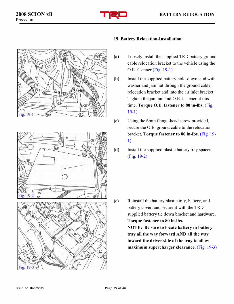
(bb) Assemble the hinge mounts on the air cleaner
inlet over the tabs on the air cleaner outlet.
(cc) The lower side of both the air cleaner inlet and
outlet should be even with each other.
(dd) Snap both spring clips into place to secure the
inlet to the outlet side. (Fig. 18-22)
(ee) Insert air cleaner assembly steady bracket into
factory plastic clip as shown. (Fig. 18-23)
(ff) Reinstall the driver side inner fender.
2008 SCION xB BATTERY RELOCATION Procedure
Issue A: 04/28/08 Page 39 of 48
19. Battery Relocation-Installation
(a) Loosely install the supplied TRD battery ground
cable relocation bracket to the vehicle using the
O.E. fastener (Fig. 19-1)
(b) Install the supplied battery hold-down stud with
washer and jam nut through the ground cable
relocation bracket and into the air inlet bracket.
Tighten the jam nut and O.E. fastener at this
time. Torque O.E. fastener to 80 in-lbs. (Fig.
19-1)
(c) Using the 6mm flange-head screw provided,
secure the O.E. ground cable to the relocation
bracket. Torque fastener to 80 in-lbs. (Fig. 19-
1)
(d) Install the supplied plastic battery tray spacer.
(Fig. 19-2)
(e) Reinstall the battery plastic tray, battery, and
battery cover, and secure it with the TRD
supplied battery tie down bracket and hardware.
Torque fastener to 80 in-lbs.
NOTE: Be sure to locate battery in battery
tray all the way forward AND all the way
toward the driver side of the tray to allow
maximum supercharger clearance. (Fig. 19-3)
2008 SCION xB MAF TUBE INSTALLATION Procedure
Issue A: 04/28/08 Page 40 of 48
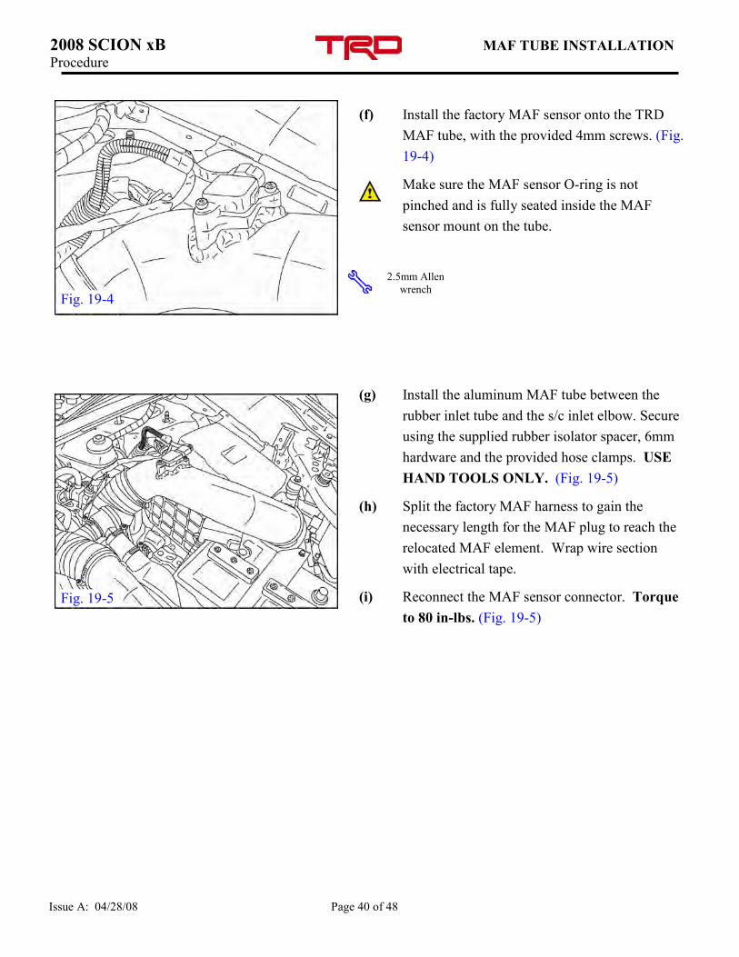
(f) Install the factory MAF sensor onto the TRD
MAF tube, with the provided 4mm screws. (Fig.
19-4)
Make sure the MAF sensor O-ring is not
pinched and is fully seated inside the MAF
sensor mount on the tube.
(g) Install the aluminum MAF tube between the
rubber inlet tube and the s/c inlet elbow. Secure
using the supplied rubber isolator spacer, 6mm
hardware and the provided hose clamps. USE
HAND TOOLS ONLY. (Fig. 19-5)
(h) Split the factory MAF harness to gain the
necessary length for the MAF plug to reach the
relocated MAF element. Wrap wire section
with electrical tape.
(i) Reconnect the MAF sensor connector. Torque
to 80 in-lbs. (Fig. 19-5)
2.5mm Allen
wrench Fig. 19-4
Fig. 19-5
2008 SCION xB FINAL ASSEMBLY Procedure
Issue A: 04/28/08 Page 41 of 48
20. Final Assembly
(a) Be sure both coolant system drain cocks are
closed. Engine block drain cock should be
torqued to 9 ft-lbs. Pour any remaining OE
coolant back into radiator filler mouth. Use
only Toyota Super Long Life Coolant or
equivalent. Fill system up with coolant/water
mix (approximately 50-50). Close bleeder port
when done. Cap radiator. Wipe up any spilled
or excess coolant.
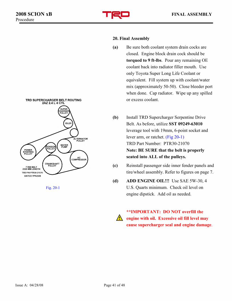
(b) Install TRD Supercharger Serpentine Drive
Belt. As before, utilize SST 09249-63010
leverage tool with 19mm, 6-point socket and
lever arm, or ratchet. (Fig 20-1)
TRD Part Number: PTR30-21070
Note: BE SURE that the belt is properly
seated into ALL of the pulleys.
(c) Reinstall passenger side inner fender panels and
tire/wheel assembly. Refer to figures on page 7.
(d) ADD ENGINE OIL!!! Use SAE 5W-30, 4
U.S. Quarts minimum. Check oil level on
engine dipstick. Add oil as needed.
**IMPORTANT: DO NOT overfill the
engine with oil. Excessive oil fill level may
cause supercharger seal and engine damage.
Fig. 20-1
2008 SCION xB FINAL ASSEMBLY Procedure
Issue A: 04/28/08 Page 42 of 48
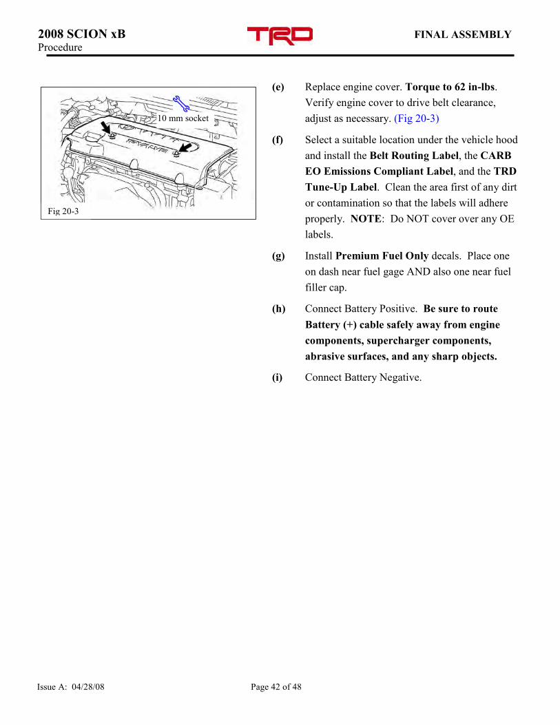
(e) Replace engine cover. Torque to 62 in-lbs.
Verify engine cover to drive belt clearance,
adjust as necessary. (Fig 20-3)
(f) Select a suitable location under the vehicle hood
and install the Belt Routing Label, the CARB
EO Emissions Compliant Label, and the TRD
Tune-Up Label. Clean the area first of any dirt
or contamination so that the labels will adhere
properly. NOTE: Do NOT cover over any OE
labels.
(g) Install Premium Fuel Only decals. Place one
on dash near fuel gage AND also one near fuel
filler cap.
(h) Connect Battery Positive. Be sure to route
Battery (+) cable safely away from engine
components, supercharger components,
abrasive surfaces, and any sharp objects.
(i) Connect Battery Negative.
10 mm socket
Fig 20-3
2008 SCION xB ECU RE-FLASH Procedure
Issue A: 04/28/08 Page 43 of 48
21. ECU Re-flash
(a) The proper procedure to re-flash the ECU
(Engine Control Unit) is explained in a
Technical Service Bulletin (SS002-07) titled
“Techstream ECU Flash Reprogramming
Procedure” located on T.I.S. (Toyota
Information System).
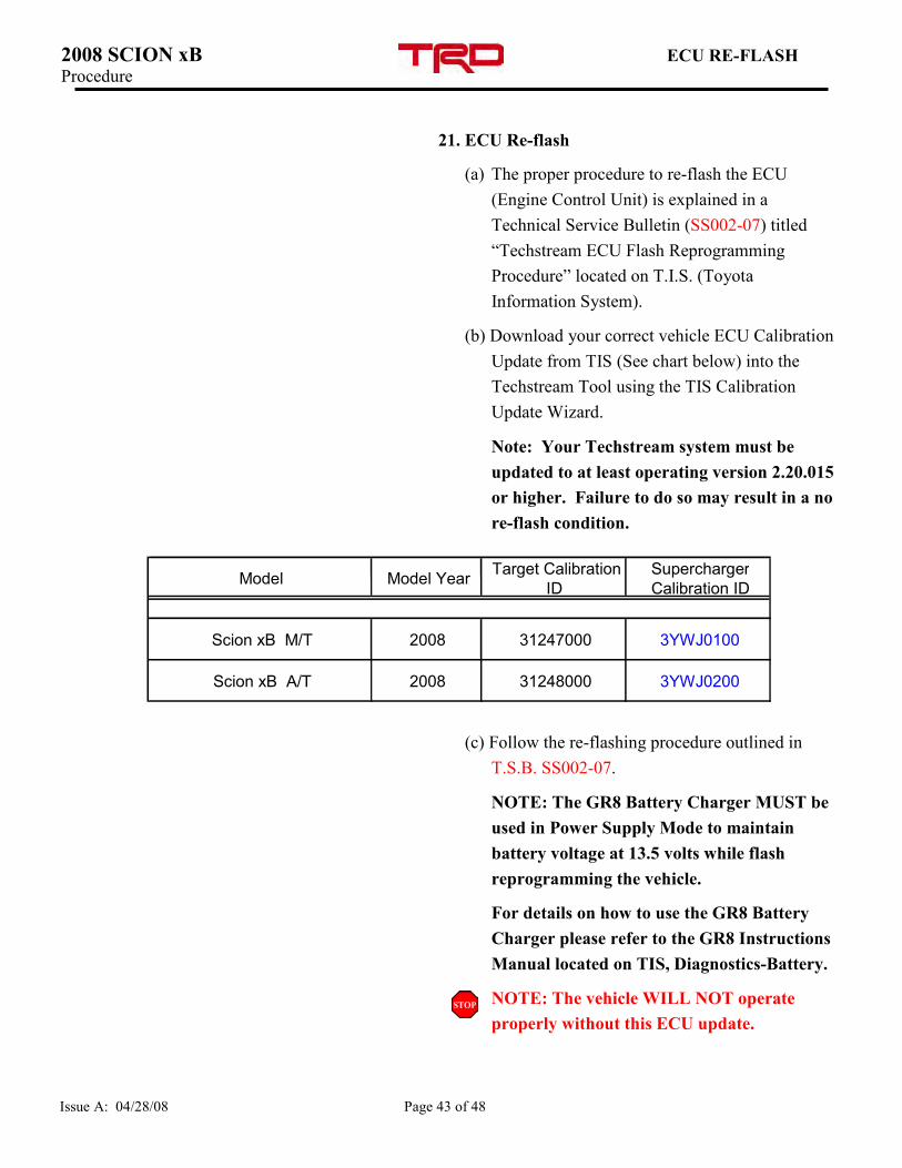
(b) Download your correct vehicle ECU Calibration
Update from TIS (See chart below) into the
Techstream Tool using the TIS Calibration
Update Wizard.
Note: Your Techstream system must be
updated to at least operating version 2.20.015
or higher. Failure to do so may result in a no
re-flash condition.
(c) Follow the re-flashing procedure outlined in
T.S.B. SS002-07.
NOTE: The GR8 Battery Charger MUST be
used in Power Supply Mode to maintain
battery voltage at 13.5 volts while flash
reprogramming the vehicle.
For details on how to use the GR8 Battery
Charger please refer to the GR8 Instructions
Manual located on TIS, Diagnostics-Battery.
NOTE: The vehicle WILL NOT operate
properly without this ECU update.
Model Model Year Target Calibration
ID
Supercharger
Calibration ID
Scion xB M/T 2008 31247000 3YWJ0100
Scion xB A/T 2008 31248000 3YWJ0200
2008 SCION xB TESTING & EVALUATION Procedure
Issue A: 04/28/08 Page 44 of 48
22. Testing and Evaluation.
(a) Start the engine and let it idle.
(b) Check the fuel system for any leaks.
(c) IMPORTANT: Check the serpentine belt drive
systems for correct alignment on ALL pulleys,
especially the TRD idler pulley.
(d) Check the coolant system for any leaks.
(i) Set the A/C system as follows:
Fan Speed Any setting except OFF
Temperature Toward Warm / Hot
A/C Switch OFF
(ii) Maintain the engine speed at 2,000 to 2,500
rpm and warm up the engine until the
cooling fan operates.
(iii) Squeeze the inlet and outlet radiator hoses
several times by hand while warming up the
engine.
(e) Check the air intake system to ensure there are
no leaks and for tightness.
(f) Stop the engine and wait for the coolant to cool
down.
(g) Carefully remove the radiator cap and check the
coolant level inside the radiator and add coolant
if necessary. Reinstall the radiator cap.
(h) Test drive the vehicle. If all is okay, park and
proceed with the next step. If not, troubleshoot
as necessary.
2008 SCION xB TESTING & EVALUATION Procedure
Issue A: 04/28/08 Page 45 of 48
(i) Use the diagnostic Techstream tool to check for
ECU error codes.
(j) Complete and mail the warranty registration
card. Note: The installation of the
Supercharger is not complete until this card
has been returned to TRD.
(k) Place all removed factory hardware,
components, and this instruction sheet into the
original TRD kit box and give to the customer
and / or place it in the vehicle cargo
compartment.
(l) IMPORTANT: Review with the customer/end-
user that the supercharger will have a slight
rattling and or chirping sound especially at idle
and that these are normal noises for this type
of supercharger.
(m) IMPORTANT: Review with the
customer/end-user that it is it is imperative that
only 91 octane (or higher) fuel be used after
the supercharger is installed. Performance will
suffer and engine damage is possible otherwise.
2008 SCION xB FINAL FUNCTION CHECKLIST
pROCEDURE Procedure
Page 46 of 48
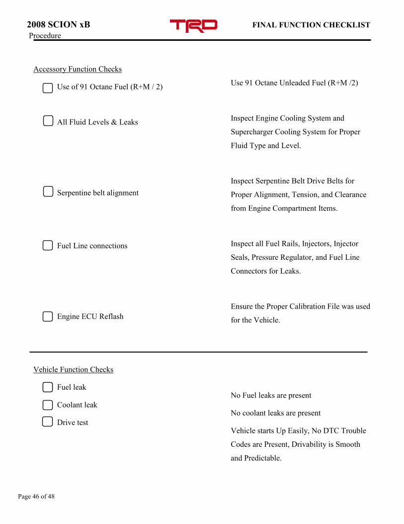
Accessory Function Checks
Use of 91 Octane Fuel (R+M / 2)
All Fluid Levels & Leaks
Serpentine belt alignment
Fuel Line connections
Engine ECU Reflash
Vehicle Function Checks
Fuel leak
Coolant leak
Drive test
Use 91 Octane Unleaded Fuel (R+M /2)
Inspect Engine Cooling System and
Supercharger Cooling System for Proper
Fluid Type and Level.
Inspect Serpentine Belt Drive Belts for
Proper Alignment, Tension, and Clearance
from Engine Compartment Items.
Inspect all Fuel Rails, Injectors, Injector
Seals, Pressure Regulator, and Fuel Line
Connectors for Leaks.
Ensure the Proper Calibration File was used
for the Vehicle.
No Fuel leaks are present
No coolant leaks are present
Vehicle starts Up Easily, No DTC Trouble
Codes are Present, Drivability is Smooth
and Predictable.
2008 SCION xB MAINTENANCE (INTAKE) Procedure
Issue A: 04/28/08 Page 47 of 48
23. Caring For The Finish On Your TRD Air Intake
& Discharge System
o TRD intakes have a protective clear
powdercoat finish that ensures a
maintenance free shine.
o To clean your TRD intake, simply spray
with window cleaner and wipe with a soft,
clean terry-cloth towel.
o NEVER use harsh chemicals or metal polish
on TRD intakes. Harsh chemicals and metal
polishes will permanently damage the finish
of your intake.
Air Filter Maintenance
Service Intervals- Service your TRD filter
element with TRD's filter cleaning system
(Toyota p/n PTR05-00000-CL) at least
every 50,000 miles to maintain optimum
performance. We recommend that TRD
filter elements be serviced every 30,000
miles for off-road and high-performance
street applications.
If you live in a region with extremely fine
dust (arid or desert climates for example),
follow the recommended schedule for off-
road and high-performance vehicles.
Do not over-oil the filter. This could
contaminate the MAF sensor and cause the
MIL (Malfunction Indicator Lamp) to
illuminate and require non-warrantable
repairs.

Page 48 of 48