scientific equipment & furniture association sefa 8-m-2010 … · scientific equipment &...
TRANSCRIPT
Scientific Equipment & Furniture Association SEFA 8-M-2010
Recommended Practices For Metal Laboratory Grade Furniture,
Casework, Shelving and Tables
®
SEFA World Headquarters 1205 Franklin Avenue—Ste 320—Garden City, NY 11530
Tel: 516-294-5424—Fax: 516-294-2758 www.sefalabs.com
—SE
FA 8-M
—
ME
TA
L C
ASE
WO
RK
©2010 SEFA—4th Edition Desk Reference, Version 1.0 177

Page Sub-Committee Members…………... 180 Forward ……………………………… 181 Sections 1.0 Scope …………………………… 182 2.0 Purpose ………………………… 182 3.0 Definitions ……………………… 182
3.1 Description of TestingApparatus 4.0 Base Cabinets ………………….. 185
4.1 Description of Test Unit 4.2 Cabinet Load Test
4.2.1 Purpose of Test 4.2.2 Test Procedure
4.2.3 Acceptance Level 4.3 Cabinet Concentrated Load Test
4.3.1 Purpose of Test 4.3.2 Test Procedure 4.3.3 Acceptance Level
4.4 Cabinet Torsion 4.4.1 Purpose of Test 4.4.2 Test Procedure 4.4.3 Acceptance Level
4.5 Cabinet Submersion Test Not applicable to Metal Casework 4.6 Spill Containment Test
Not applicable to Metal Casework 5.0 Doors …………………………… 187
5.1 Door Hinge Test 5.1.1 Purpose of Test 5.1.2 Test Procedure 5.1.3 Acceptance Level 5.2 Door Impact Test 5.2.1 Purpose of Test 5.2.2 Test Procedure 5.2.3 Acceptance Level 5.3 Door Cycle Test 5.3.1 Purpose of Test 5.3.2 Test Procedure 5.3.3 Acceptance Level
6.0 Drawers ………………………… 188 6.1 Drawer Static Test 6.1.1 Purpose of Test
Page 6.1.2 Test Procedure 6.1.3 Acceptance Level 6.2 Drawer and Door Pull Test 6.2.1 Purpose of Test 6.2.2 Test Procedure 6.2.3 Acceptance Level 6.3 Drawer Impact Test 6.3.1 Purpose of Test 6.3.2 Test Procedure 6.3.3 Acceptance Level 6.4 Drawer Internal Impact 6.4.1 Purpose of Test 6.4.2 Test Procedure 6.4.3 Acceptance Level 6.5 Drawer Cycle Test 6.5.1 Purpose of Test 6.5.2 Test Procedure 6.5.3 Acceptance Level
7.0 Shelving ……………………….. 191 7.1 Description of Test Unit 7.2 Load Test
7.2.1 Purpose of Test 7.2.2 Test Procedure 7.2.3 Acceptance Level
8.0 Cabinet Surface Finish Tests…. 191 8.1 Chemical Spot Test
8.1.1 Purpose of Test 8.1.2 Test Procedure 8.1.3 Acceptance Level
8.2 Hot Water Test 8.2.1 Purpose of Test 8.2.2 Test Procedure
8.2.3 Acceptance Level 8.3 Impact Test
8.3.1 Purpose of Test 8.3.2 Test Procedure 8.3.3 Acceptance Level
8.4 Paint Adhesion on Steel 8.4.1 Purpose of Test 8.4.2 Test Procedure 8.4.3 Acceptance Level
8.5 Paint Hardness on Steel 8.5.1 Purpose of Test 8.5.2 Test Procedure 8.5.3 Acceptance Level
Table of Contents
—SE
FA 8
-M—
M
ET
AL
CA
SEW
OR
K
©2010 SEFA—4th Edition Desk Reference, Version 1.0 178

Page 8.6 Dart Impact Test Not applicable to Metal Casework 8.7 Edge Delaminating Tests Not applicable to Metal Casework 8.8 Edge Impact Test Not applicable to Metal Casework 8.9 Wear Resistance (Abrasion) Test Not applicable to Metal Casework
9.0 Wall Cabinets, Counter Mounted, and Tall Units……… 195
9.1 Description of Test Unit 9.2 Load Test 9.2.1 Purpose of Test 9.2.2 Test Procedure 9.2.3 Acceptance Level
10.0 Tables ………………………….. 195 10.1Description of Test Unit
10.2 Load Test 10.2.1 Purpose of Test 10.2.2 Test Procedure 10.2.3 Acceptance Level
10.3 Table Racking 10.3.1 Purpose of Test 10.3.2 Test Procedure 10.3.3 Acceptance Level Endnotes ……………………………… 197 SEFA-Approved Product Testing Facilities ……………………………… 198 Forms ………………………………… 199
—SE
FA 8-M
—
ME
TA
L C
ASE
WO
RK
©2010 SEFA—4th Edition Desk Reference, Version 1.0 179

SEFA 8-M Sub-Committee Members
Jim Arthurs, SEFA 8 Committee Chair ………...……CampbellRhea
Rick Johnson, Sub-Committee Chair …..….. ………..Thermo Fisher Scientific
Dana Dahlgren, Co-Chair……………………………. Kewaunee Scientific
Pierre Poirier………………………..……………….Bedcolab
David Campbell………….……………………………… HEMCO Corporation
Mike Cook……………………………………………….Jamestown Metal Products, Inc.
Sam LaMancuso ………………………………………...Jamestown Metal Products, Inc.
Bob DeLuca………………………………….……..…....Lab Crafters, Inc.,
Don Nelson …..………………………………………….Air Master Systems
Paul Northam………………………………………….....Eagle MHC
Brent Renkema…………………………………………..Steelcase
—SE
FA 8
-M—
M
ET
AL
CA
SEW
OR
K
©2010 SEFA—4th Edition Desk Reference, Version 1.0 180
—SE
FA 8-M
—
ME
TA
L C
ASE
WO
RK
Forward
SEFA Profile The Scientific Equipment and Furniture Association (SEFA) is an international trade association com-prised of manufacturers of laboratory furniture, casework, fume hoods and members of the design and installation professions. The Association was founded to promote this rapidly expanding industry and improve the quality, safety and timely completion of laboratory facilities in accordance with customer requirements.
SEFA Recommended Practices SEFA and its committees are active in the development and promotion of Recommended Practices hav-ing domestic and international applications. Recommended Practices are developed by the association taking into account the work of other standard writing organizations. Liaison is also maintained with government agencies in the development of their specifications. SEFA’s Recommended Practices are developed in and for the public interest. These practices are de-signed to promote a better understanding between designers, architects, manufacturers, purchasers, and end-users and to assist the purchaser in selecting and specifying the proper product to meet the user’s particular needs. SEFA’s Recommended Practices are periodically updated. The Recommended Prac-tices are numbered to include an annual suffix which reflects the year that they were updated. SEFA encourages architects to specify these Recommended Practices as follows: “SEFA 8M-2010”.
SEFA Glossary of Terms
SEFA has developed a Glossary of Terms (SEFA 4-2010) for the purpose of promoting a greater under-standing between designers, architects, manufacturers, purchasers and end users. The terms defined by SEFA are frequently used in contracts and other documents, which attempt to define the products to be furnished or the work involved. The Association has approved this Glossary in an effort to provide uni-formity among those who use these terms. Where a specific Recommended Practice contains definitions which differ from those in the Glossary of Terms, then the definitions in the specific Recommended Practice should be used. SEFA encourages all interested parties to submit additional terms or to suggest any changes to those terms already defined by the Association. The definitions should be used to help resolve any disputes that may arise or to incorporate the applicable terms in any contract or related documents.
SEFA Disclaimer SEFA uses its best effort to promulgate Recommended Practices for the benefit of the public in light of available information and accepted industry practices. SEFA does not guarantee, certify, or assure the safety or performance of any products, components, or systems tested, installed, or operated in accor-dance with SEFA Recommended Practices or that any tests conducted under its Recommended Practices will be non-hazardous or free from risk.
©2010 SEFA—4th Edition Desk Reference, Version 1.0
Note : Testing as described in this document must be performed and documented by a SEFA-approved third party testing facility. See Page 198.
181

1.0 Scope
SEFA recommended practices are intended to provide manufactures, specifiers, and users tools for evaluating the safety, durability, and structural integrity of metal laboratory grade casework and complementary items.2 The scope of this document is inclusive of case-work (base units, wall mounted units, counter mounted units, tall units), shelving and table systems. Casework, shelving, and tables, manufactured for laboratory use should be sub-jected to the following tests and procedures. Great care should be exercised when heavy loads are applied to the cabinet and appropriate safety precautions taken to insure safety to test-ing personnel. All tests should be performed by properly trained personnel. SEFA assumes no liability for damage or injury as a result of con-ducting these tests. The acceptance levels are based on the cumu-lative experience of actual field testing and laboratory results of SEFA (Scientific Equip-ment and Furniture Association) members. Unless noted otherwise, all weights and dimen-sions shown shall have a tolerance of ± 2%. Testing as described in this document must be performed and documented by a SEFA-approved third party testing facility. 2.0 Purpose
The purpose of this document is to describe the means of evaluating the function and safety of metal laboratory grade casework and comple-mentary items. Cabinets shall be of a type specifically de-signed and manufactured for installation and use in a laboratory. Cabinet hardware and ma-terials shall be of appropriate quality and type for the purpose intended. Construction shall conform to the best practices of the scientific casework industry. Joints and corners shall be well fitted, eliminating unsightly openings and seams. Edges or corners that may, in normal use, come into contact with laboratory person-nel shall be free of burrs, and sharp or rough
edges. Product finish shall be resistant to chemical spills and splashes common to a typi-cal laboratory operation. Structural strength shall be adequate to support heavy laboratory apparatus, high-density shielding, or containers and heavy instruments. Although aggregate test results may vary from manufacturer to manufacturer, procedures for testing performance criteria shall be as outlined in this document and results made available upon request. It is assumed that the test model reflects the performance criteria for all product regardless of construction, material, size, or style used. A test unit has been identified in this document with the sole purpose of obtain-ing continuity of procedures and results in a scientific format. Different styles, materials, and construction methods used may yield dif-ferent results and therefore should be tested as a different test model. 3.0 Definitions Acceptance Levels - The acceptance level for each performance criteria is based on the cu-mulative experience of actual field testing and laboratory results of SEFA members. Accep-tance levels describe the expected outcome of each test procedure. ANSI/BIFMA - ANSI is the American Na-tional Standards Institute. Approval of an American National Standard requires verifica-tion by ANSI that the requirements for due process, consensus, and other criteria for ap-proval have been met by the standards devel-oper. BIFMA is the Business and Institutional Furniture Manufacturer's Association, an asso-ciation of manufacturers of desk products and the like. Apparatus - A machine or group of machines and accessories. Arithmetic Mean - A number obtained by di-viding the sum of a set of quantities by the number of quantities in a set; average. ASTM - American Society for Testing and
—SE
FA 8
-M—
M
ET
AL
CA
SEW
OR
K
©2010 SEFA—4th Edition Desk Reference, Version 1.0 182

Materials. Base Cabinets - A base cabinet is a storage devise consisting of two ends, a back, and a face. The face may be open, to access the stor-age area, or may be outfitted with one or more drawers and/or doors. The base cabinet may or may not include a top. A base cabinet is al-ways mounted on the floor and normally sup-ports a surface. The top surface is normally no more than 42" (1,066.8mm) off the floor sur-face. Best Practices - When given a choice of grade, the "best practice" is to select one that offers a well defined degree of control over the quality of workmanship, materials, and installation of a project. SEFA-8 Recommended Practices are written from a view of high quality laboratory furniture. Cabinet Depth (Deep) - Given a front, bottom, two sides, and a top, the cabinet depth is a measure of the side of the cabinet, in its normal upright position, from the back to the front. Cabinet Height (High) - Given a front, bot-tom, two sides, and a top, the cabinet height is a measure of the side of the cabinet, in its nor-mal upright position, from the bottom to the top, excluding any additional surface. Cabinet Width (Wide) - Given a front, bot-tom, two sides, and a top, the cabinet width is a measure of the front of the cabinet in its normal upright position from one side to the other. Casework - Base and wall cabinets, display fixtures, and storage shelves. The generic term for both "boxes" and special desks, reception counters, nurses stations and the like. Gener-ally includes the tops and work surfaces. Chase (Plumbing Area) - Space located be-hind the back of the base cabinet used to house plumbing or electric lines. Counter Mounted Cabinet - A counter mounted cabinet is a wall cabinet (usually with a height of approximately 48" [1,219.2mm]
and is typically mounted on the work surface or shelf, as in a reagent shelf). Cupboard (Door Unit) - That portion of the cabinet with no drawer(s) that may be enclosed by doors, Combination Unit - A base unit of the type that has both door(s) and drawer(s). Drawer - A sliding storage box or receptacle opened by pulling out and closed by pushing in. Free Standing - Requiring no support or fas-tening to other structures. Hardware - Manufactured articles used in pro-ducing cabinets. Such articles include items such as screws, pulls, hinges, and drawer slides. Polypropylene hardware to exhibit no exposed metal for increased corrosive resis-tance. High Density Shielding - A barrier made of lead. Joinery - The junction of two pieces intended to be permanently connected, using standard thermoplastic welding practices. Laboratory Furniture - Furniture designed and manufactured for installation and use in a laboratory. Latch - A piece of hardware designed to hold a door closed. Leveling Screws (Levelers) - Threaded com-ponents designed to allow adjustment of the cabinet vertically as needed for leveling. Nominal Dimensions - Not all cabinet manu-facturers produce product to the identical di-mensions. All dimensions given in this docu-ment are accurate to within five percent, which is considered nominal. Permanent Damage - Destruction to material or joinery that would require repair in order to
—SE
FA 8-M
—
ME
TA
L C
ASE
WO
RK
©2010 SEFA—4th Edition Desk Reference, Version 1.0 183

return to its original state. Permanent Deformation - Deflection that has exceeded the plastic limit, thus changing the original shape of the product. Permanent Deterioration - Erosion or corro-sion of material such that the component will never return to its original shape. Permanent Failure - See "permanent dam-age." Pulls - Articles used to grasp the door or drawer (see also hardware). Rack Resistance - The ability of a desk prod-uct to resist stresses that tend to make the prod-uct distort and the drawers to become mis-aligned. Rail - A bar extending from one side of the cabinet to the other. Reagent - A substance used because of its chemical or biological activity.8
Removable Back - A panel located on the in-side back of the base cabinet, which is remov-able in order to gain access to the plumbing area. Shelving - A flat panel supported horizontally in a cabinet interior, wall, or other support structure used to hold objects. Stainless Steel - Steels containing more chro-mium than the 12% necessary to produce pas-sivity (less reactive), but less than 30%.9 These steels resist corrosion under normal conditions and are usually non-magnetic. Submersion - Covered with water. Tables - An article of furniture having a flat, horizontal surface supported by one or more support members (legs), and a frame (apron). Tall Cabinet (Full Height Unit) - A tall cabi-net is a storage devise that consists of two
sides, a bottom, a top, a back, and a face. The face may be open to access the storage area or may be outfitted with one or more drawers and/or door(s). A tall cabinet is always mounted on the floor and is nominally above 60" (1524mm) high. Torsion – A force acting at a distance which tends to twist or rotate an object or cabinet. Uniformly Distributed – A force applied evenly over the area of a surface. Unobstructed Entry - A cabinet is deemed to be unobstructed if access to the entire storage area is completely without obstacle. Upright Position - A cabinet oriented in its intended position. Wall Cabinet - A wall cabinet is a storage de-vice consisting of two ends, a back, a top, bot-tom, and a face. The face may be open to ac-cess the storage area or may be outfitted with one or more door(s). The wall cabinet usually does not include a drawer. A wall cabinet is always mounted on a vertical surface such as a wall, a divider, panel or some other vertical structure. A wall cabinet is usually less than 48" (1,219mm) high. Work Surface - A normally horizontal surface used to support apparatus at a convenient height off the floor. Work Surfaces are nor-mally positioned atop a base cabinet or table structure. 3.1 Description of Testing Apparatus Solid Steel Bar - A square solid steel bar 2 1/2" (63mm) square, 28 1/4" (717mm) long, weighing 50 pounds (22.679 Kg). Sand or Shot Bag (10 pounds [4.545 Kg]) - A bag of plastic or cloth with the approximate dimensions 10 9/16" (268mm) x 11" (279mm) as in typical "gallon size re-closable storage bags." Filled with enough sand or shot so that contents weigh 10 pounds (4.545 Kg).
—SE
FA 8
-M—
M
ET
AL
CA
SEW
OR
K
©2010 SEFA—4th Edition Desk Reference, Version 1.0 184

Sand Bag (20 pounds [9.071 Kg]) - Two 10 pound (4.545 Kg) sand bags bound together. Shot Bag (100 lbs. [45.359 Kg]) - A plastic or cloth bag of sufficient size to contain 100 pounds (45.359 Kg) of shot. Cycling Mechanism - Per ANSI BHMA 156.9.-2003 Steel Rod - A 2" (51mm) diameter by 12" (305mm) long rod, approximately 10 pounds (4.535 Kg) in weight. Hot Water - To be considered "hot water," the temperature of the water must be between 190º F to 205º F (88º C to 96º C). One Pound Ball - Solid steel sphere approxi-mately 2" (51mm) in diameter. Hardwood Corner Block - A block of hard-wood 2" (51mm) square by 1" (25.4mm) high. 4.0 Base Cabinets 4.1 Description of Test Cabinet The base cabinet shall be a combination of cupboard and drawer per Figure 1. The base
cabinet shall have nominal dimensions ±1”(25.4mm) of 48" (1,219.2mm) wide, 35" (889.0mm) high, and 22" (558.8mm) deep. The drawer shall be above the cupboard, full width and approximately one-fourth the height of the cabinet’s face opening. The inside depth of the drawer shall be no less than
18”(457.2mm). The drawer in the full open position shall expose no less than 2/3 of the drawer interior. Cupboard shall be double-door design and provide unobstructed entry into the cabinet interior with the doors open. The unit shall contain one adjustable shelf. The cabinet back shall be the removable type (per manufac-tures standard design as used for access to the plumbing or chase area) with the removable panel removed. The cabinet shall be free standing, squared and leveled and sitting 1" (25.4mm) off the floor on all four leveling screws. When leveling screws are not required, the cabinet shall be squared and leveled and sitting 1" (25.4mm) off the floor atop four hardwood corner blocks 2" (50.8mm) square and 1" (25.4mm) high. A top of 1" (25.4mm) thick 37-50 pcf medium density fiberboard shall be freely positioned on the cabinet without glue or fasteners of any kind. The top dimensions will be such that it will overhang the cabinet perimeter by 1" (25.4mm). Its weight shall be included in the test as live load. Before conducting the test, a visual examination shall be conducted to verify that the unit configuration and setup conditions are appropriate. Operate doors and drawers. Doors should be free moving and latch properly. Inspect the unit for dimensions and note the fit of doors and drawers to the cabinet body. Open and close the drawer. The drawer should be free moving and function as specified by the manufacturer. Discontinue evaluation if unit is not in compliance or if malfunction is noted. 4.2 Cabinet Load Test 4.2.1 Purpose of Test The cabinet load test will challenge the struc-tural integrity and load bearing capability of the cabinet construction. This test will demon-strate the ability of the cabinet to support heavy applied loads. This is not intended to test the functional characteristics of the cabinet under heavy loads.
—SE
FA 8-M
—
ME
TA
L C
ASE
WO
RK
©2010 SEFA—4th Edition Desk Reference, Version 1.0 185

4.2.2 Test Procedure Verify that the cabinet is level and supported only by the levelers. Load the cabinet top by using 2000 pounds (907.2 Kg) of solid steel bars (per Section 3.1) stacked five high and spaced per Figure 2. After ten minutes, unload the cabinet. 4.2.3 Acceptance Level The cabinet will have no signs of permanent failure. After the load is removed, inspect the levelers. Any deformation shall not interfere with the function of the leveling system. 4.3 Cabinet Concentrated Load Test 4.3.1 Purpose of Test The purpose of this test is to challenge the functional characteristics of the cabinet when subjected to a concentrated load on the center of the cabinet top. 4.3.2 Test Procedure Using solid weights or 10 pound (4.535 Kg) sand bags (per Section 3.1), apply a total of 200 pounds (90.718 Kg) to the top of the cabi-net along the cabinet centerline (see Figure 3). Operate doors and drawers.
4.3.3 Acceptance Level Door and drawer operation shall be normal un-der condition of test load. There shall be no signs of permanent deformation to front rail, cabinet joinery, doors, or drawers. 4.4 Cabinet Torsion 4.4.1 Purpose of Test This test will evaluate the structural integrity of the cabinet construction when subjected to a torsional load. 4.4.2 Test Procedure The cabinet shall be tested in its normal up-right position, raised not less than four-inches off the floor and supported on rear and one front corner. The area of support under the cabinet shall be centered on the leveling feet of the cabinet. Secure the cabinet diagonally from the supported corner with seven solid steel bars per Section 3.1 (350 pounds (158.76 Kg) of weight), on the top of the cabinet to prevent over-turning. Apply four solid steel bars (200 pounds (90.72 Kg) of weight) to the unsup-ported corner for a period of fifteen minutes (see Figure 4). Remove weight and place cabi-net on the floor in its normal upright position. Observe cabinet joinery. Level the cabinet and measure the face and back of the cabinet across the diagonal corners.
—SE
FA 8
-M—
M
ET
AL
CA
SEW
OR
K
©2010 SEFA—4th Edition Desk Reference, Version 1.0 186

4.4.3 Acceptance Level When returned to normal position, the opera-tion of the cabinet shall be normal, and there will be no signs of permanent damage. The difference between the two measurements taken from measuring the diagonal corners shall be no more than 1/8" (3.175mm). 4.5 Cabinet Submersion Test
Not applicable to Metal Casework. 4.6 Spill Containment Test
Not applicable to Metal Casework. 5.0 Doors 5.1 Door Hinge Test 5.1.1 Purpose of Test This test will demonstrate the durability of the door and its hardware (hinge leaf, screws, etc.) to an applied load of 200 pounds (90.72 Kg). 5.1.2 Test Procedure Remove the shelf for this test. With unit and top set as described in Section 4.1, add suffi-cient weight to the top in order to prevent over-
turning. With cabinet door opened 90-degrees, hang a sling made up of two 100 pound (45.36 Kg) weights (shot bags or solid weights) over top of the door at a point 12" (304.8mm) out from the hinge centerline (see Figures 5a and 5b). Grasping the door by the handle, slowly (8 to 10 seconds) move door through the full cy-cle of the hinge, up to a 160 degree arc. Re-
—SE
FA 8-M
—
ME
TA
L C
ASE
WO
RK
©2010 SEFA—4th Edition Desk Reference, Version 1.0 187

move weight and swing door through its full intended range of motion and close door. Re-peat on other door. 5.1.3 Acceptance Level The open door shall withstand a load of 200 pounds (90.72 Kg) when applied at a point 12" (304.8mm) from the hinge centerline with-out permanent damage. Operation of the door, after test, shall show no permanent damage that will cause binding of the door or hinges or that will adversely affect operation of the catch. Both doors must meet the above criteria. 5.2 Door Impact Test 5.2.1 Purpose of Test This test will demonstrate the resistance of a 240 inch-pound (27.1 N-m) impact to the door face. Only units that extend below the work surface should be subjected to this test. This test should not be inclusive of glass doors. 5.2.2 Test Procedure With unit and top set as described in Section 4.1, add sufficient weight to the top in order to prevent overturning. A 20 pound (9.07 Kg) sand bag (per Section 3.1) shall be suspended and dropped to provide an impact of 240 inch-pounds (27.1 N-m) at the center of the closed door. (see Figure 6.)
5.2.3 Acceptance Level After the test, the door and catch shall operate normally and show no signs of permanent damage. A dent or depression is an indication of permanent damage. This test is not in-tended to evaluate the cabinet finish. 5.3 Door Cycle Test 5.3.1 Purpose of Test This test will demonstrate the durability of the door hinge hardware to withstand 100,000 cy-cles as a reliable measure for longevity). 5.3.2 Test Procedure This test shall be in conformance to the ANSI test procedure A156.9, Grade 1, requirements for cycle testing of doors. A cycling mecha-nism shall swing door 90-degrees. Door shall operate for 100,000 cycles with a speed not greater than 15 cycles per minute. 5.3.3 Acceptance Level Door shall operate for the full cycle period without deterioration that will significantly af-fect the function of the door. The door shall operate freely without binding. 6.0 Drawers 6.1 Drawer Static Test 6.1.1 Purpose of Test This test will demonstrate the ability to support a point load given to the front of the drawer and will challenge the drawer suspension system and the attachment of the drawer head to the drawer.
6.1.2 Test Procedure With unit and top set as described in Section 4.1, add sufficient weight to the top in order to prevent overturning. Open the drawer to 13" (330.2mm) of travel and, using a 1” wide
—SE
FA 8
-M—
M
ET
AL
CA
SEW
OR
K
©2010 SEFA—4th Edition Desk Reference, Version 1.0 188
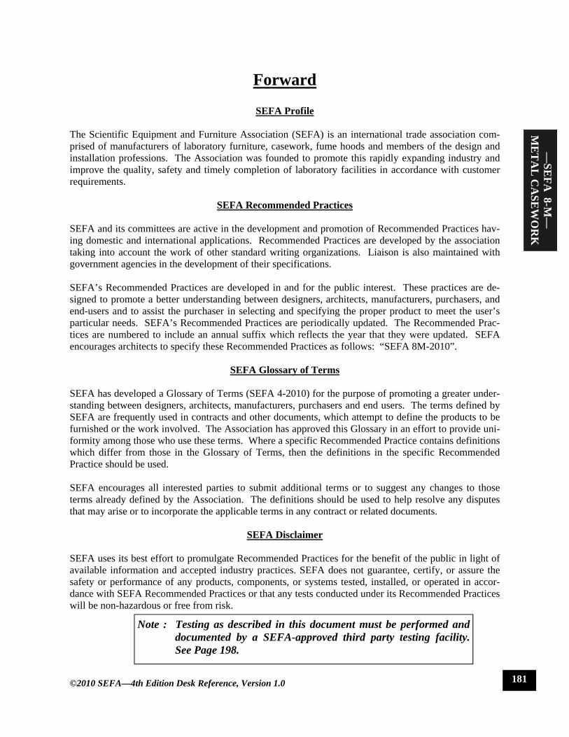
bracket, hang 150 pounds (68.04 Kg) from the drawer head at the centerline of the drawer for five minutes (see Figure 7). Remove the weight and operate the drawer through the full cycle.
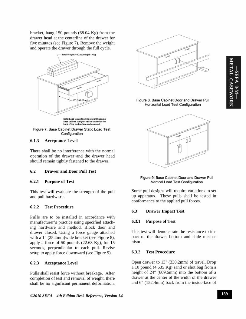
6.1.3 Acceptance Level There shall be no interference with the normal operation of the drawer and the drawer head should remain tightly fastened to the drawer. 6.2 Drawer and Door Pull Test 6.2.1 Purpose of Test This test will evaluate the strength of the pull and pull hardware. 6.2.2 Test Procedure Pulls are to be installed in accordance with manufacturer’s practice using specified attach-ing hardware and method. Block door and drawer closed. Using a force gauge attached with a 1” (25.4mm)wide bracket (see Figure 8), apply a force of 50 pounds (22.68 Kg), for 15 seconds, perpendicular to each pull. Revise setup to apply force downward (see Figure 9). 6.2.3 Acceptance Level Pulls shall resist force without breakage. After completion of test and removal of weight, there shall be no significant permanent deformation.
—SE
FA 8-M
—
ME
TA
L C
ASE
WO
RK
Some pull designs will require variations to set up apparatus. These pulls shall be tested in conformance to the applied pull forces. 6.3 Drawer Impact Test 6.3.1 Purpose of Test This test will demonstrate the resistance to im-pact of the drawer bottom and slide mecha-nism. 6.3.2 Test Procedure Open drawer to 13" (330.2mm) of travel. Drop a 10 pound (4.535 Kg) sand or shot bag from a height of 24" (609.6mm) into the bottom of a drawer at the center of the width of the drawer and 6" (152.4mm) back from the inside face of
©2010 SEFA—4th Edition Desk Reference, Version 1.0 189
the drawer. Remove the sand or shot bag. 6.3.3 Acceptance Level Operate drawer through full cycle. Drawer shall operate normally. Any deformation will not cause binding or interfere with the opera-tion of the drawer. 6.4 Drawer Internal Rolling Impact 6.4.1 Purpose of Test This test will evaluate the strength of the drawer head, bottom, and back as a result of opening and closing the drawer with a rolling load. 6.4.2 Test Procedure
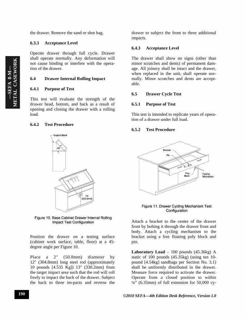
Position the drawer on a testing surface (cabinet work surface, table, floor) at a 45-degree angle per Figure 10. Place a 2" (50.8mm) diameter by 12" (304.8mm) long steel rod (approximately 10 pounds [4.535 Kg]) 13" (330.2mm) from the target impact area such that the rod will roll freely to impact the back of the drawer. Subject the back to three im-pacts and reverse the
drawer to subject the front to three additional impacts. 6.4.3 Acceptance Level The drawer shall show no signs (other than minor scratches and dents) of permanent dam-age. All joinery shall be intact and the drawer, when replaced in the unit, shall operate nor-mally. Minor scratches and dents are accept-able. 6.5 Drawer Cycle Test 6.5.1 Purpose of Test This test is intended to replicate years of opera-tion of a drawer under full load. 6.5.2 Test Procedure
Attach a bracket to the center of the drawer front by bolting it through the drawer front and body. Attach a cycling mechanism to the bracket using a free floating poly block and pin. Laboratory Load – 100 pounds (45.36kg) A static of 100 pounds (45.35kg) (using ten 10-pound [4.54kg] sandbags per Section No. 3.1) shall be uniformly distributed in the drawer. Measure force required to activate the drawer. Operate from a closed position to within ¼” (6.35mm) of full extension for 50,000 cy-
—SE
FA 8
-M—
M
ET
AL
CA
SEW
OR
K
©2010 SEFA—4th Edition Desk Reference, Version 1.0 190

cles at a rate not to exceed 10 cycles per min-ute. Heavy Duty Laboratory Load – 150 pounds (68.04kg) A static of 150 pounds (68.04kg) (using fifteen 10-pound [4.54kg] sand bags per Section No. 3.1) shall be uniformly distributed in the drawer. Measure force required to acti-vate the drawer. Operate from a closed posi-tion to within ¼” (6.35mm) of full extension for 50,000 cycles at a rate not to exceed 10 cy-cles per minute. 6.5.3 Acceptance Level The drawer shall operate freely without evi-dence of dragging, rubbing or binding. The force required to open and close loaded drawer shall not be greater than 8 pounds (3.63kg) to activate hardware.* *The American’s with Disabilities Act (ADA) re-quires a force no greater than five pounds to acti-vate hardware. The load rating in this document is intended only for testing conditions where loads challenge the durability of the hardware. Under actual conditions, drawer loading should be re-duced to levels that result in compliance with ADA as applicable. 7.0 Shelving 7.1 Description of Test Unit Metal shelving shall be tested using the follow-ing procedure. The shelves to be tested are as described in sections 4.1 and 9.1 “Description of Test Cabinet”. 7.2 Shelf Load Test 7.2.1 Purpose of Test This test will demonstrate the ability of a shelf and its mounting hardware to support normal laboratory loads. 7.2.2 Test Procedure A shelf shall be mounted in the manner in which it is designed. Measure the distance from
the underside of the shelf to a reference point perpendicular to the center of the shelf. Use shot or sand bags weighing 10 pounds (4.54 Kg) each. Unless otherwise specified, load the shelf uniformly to 40 pounds (18.14 Kg) per square foot of shelf area to a maximum of 200 pounds (90.72 Kg). Measure the deflection on the shelf by measuring the distance to the refer-ence point and calculating the difference be-tween the two measurements. Record data and remove load from the shelf. 7.2.3 Acceptance Level The allowable maximum deflection of a shelf is 1/180 of the span and not in excess of .25" (6.35mm). The following formula may be used to calculate the approximate deflection expected from a uniformly distributed load: D(max.) = 5W L^3 / 384 E I WHERE: D = Deflection in inches (Maximum 1/180 span, not to exceed .25" (6.35mm). W = (Design Load) x (Shelf Depth in Inches) x (Shelf Span in Inches) (Design Load = 40 pounds (18.14 Kg) / square foot divided by 144) “W” shall not exceed 200 pounds (90.72 Kg). L = Span between supports in inches E = Modulus of Elasticity Steel = 29 * 10^6 psi 1-M-2 I = Cross section moment of inertia. 8.0 Cabinet Surface Finish Tests 8.1 Chemical Spot Test 8.1.1 Purpose of Test The purpose of the chemical spot test is to
—SE
FA 8-M
—
ME
TA
L C
ASE
WO
RK
©2010 SEFA—4th Edition Desk Reference, Version 1.0 191
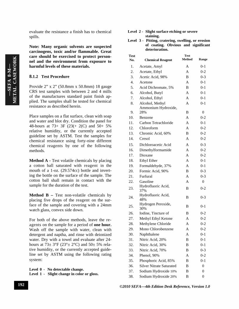
evaluate the resistance a finish has to chemical spills. Note: Many organic solvents are suspected carcinogens, toxic and/or flammable. Great care should be exercised to protect person-nel and the environment from exposure to harmful levels of these materials. 8.1.2 Test Procedure Provide 2” x 2” (50.8mm x 50.8mm) 18 gauge CRS test samples with between 2 and 4 mills of the manufactures standard paint finish ap-plied. The samples shall be tested for chemical resistance as described herein. Place samples on a flat surface, clean with soap and water and blot dry. Condition the panel for 48-hours at 73+ 3F (23(+ 2(C) and 50+ 5% relative humidity, or the currently accepted guideline set by ASTM. Test the samples for chemical resistance using forty-nine different chemical reagents by one of the following methods. Method A - Test volatile chemicals by placing a cotton ball saturated with reagent in the mouth of a 1-oz. (29.574cc) bottle and invert-ing the bottle on the surface of the sample. The cotton ball shall remain in contact with the sample for the duration of the test. Method B – Test non-volatile chemicals by placing five drops of the reagent on the sur-face of the sample and covering with a 24mm watch glass, convex side down. For both of the above methods, leave the re-agents on the sample for a period of one hour. Wash off the sample with water, clean with detergent and naptha, and rinse with deionized water. Dry with a towel and evaluate after 24-hours at 73± 3°F (23°± 2°C) and 50± 5% rela-tive humidity, or the currently accepted guide-line set by ASTM using the following rating system: Level 0 - No detectable change. Level 1 - Slight change in color or gloss.
Level 2 - Slight surface etching or severe staining. Level 3 - Pitting, cratering, swelling, or erosion of coating. Obvious and significant deterioration. Test No.
Chemical Reagent
Test Method
Range
1. Acetate, Amyl A 0-1 2. Acetate, Ethyl A 0-2 3. Acetic Acid, 98% B 0-3 4. Acetone A 0-1 5. Acid Dichromate, 5% B 0-1 6. Alcohol, Butyl A 0-1 7. Alcohol, Ethyl A 0-1 8. Alcohol, Methyl A 0-1
9. Ammonium Hydroxide, 28% B 0
10. Benzene A 0-2 11. Carbon Tetrachloride A 0-1 12. Chloroform A 0-2 13. Chromic Acid, 60% B 0-2 14. Cresol A 0-2 15. Dichloroacetic Acid A 0-3 16. Dimethylformamide A 0-2 17. Dioxane A 0-2 18. Ethyl Ether A 0-1 19. Formaldehyde, 37% A 0-1 20. Formic Acid, 90% B 0-3 21. Furfural A 0-3 22. Gasoline A 0
23. Hydrofluoric Acid, 37% B 0-2
24. Hydrofluoric Acid, 48% B 0-3
25. Hydrogen Peroxide, 30% B 0-1
26. Iodine, Tincture of B 0-2 27. Methyl Ethyl Ketone A 0-2 28. Methylene Chloride A 0-2 29. Mono Chlorobenzene A 0-2 30. Naphthalene A 0-1 31. Nitric Acid, 20% B 0-1 32. Nitric Acid, 30% B 0-1 33. Nitric Acid, 70% B 0-3 34. Phenol, 90% A 0-2 35. Phosphoric Acid, 85% B 0-1 36. Silver Nitrate Saturated B 0 37. Sodium Hydroxide 10% B 0 38. Sodium Hydroxide 20% B 0
©2010 SEFA—4th Edition Desk Reference, Version 1.0
—SE
FA 8
-M—
M
ET
AL
CA
SEW
OR
K
192
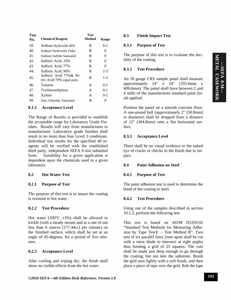
8.1.3 Acceptance Level The Range of Results is provided to establish the acceptable range for Laboratory Grade Fin-ishes. Results will vary from manufacturer to manufacturer. Laboratory grade finishes shall result in no more than four Level 3 conditions. Individual test results for the specified 49 re-agents will be verified with the established third party, independent SEFA 8 test submittal form. Suitability for a given application is dependent upon the chemicals used in a given laboratory. 8.2 Hot Water Test 8.2.1 Purpose of Test The purpose of this test is to insure the coating is resistant to hot water. 8.2.2 Test Procedure Hot water (100°C ±3%) shall be allowed to trickle (with a steady stream and at a rate of not less than 6 ounces [177.44cc] per minute) on the finished surface, which shall be set at an angle of 45-degrees, for a period of five min-utes. 8.2.3 Acceptance Level After cooling and wiping dry, the finish shall show no visible effects from the hot water.
8.3 Finish Impact Test 8.3.1 Purpose of Test The purpose of this test is to evaluate the duc-tility of the coating. 8.3.2 Test Procedure An 18 gauge CRS sample panel shall measure approximately 14" x 24" (355.6mm x 609.6mm). The panel shall have between 2 and 4 mills of the manufactures standard paint fin-ish applied. Position the panel on a smooth concrete floor. A one-pound ball (approximately 2" [50.8mm] in diameter) shall be dropped from a distance of 12" (304.8mm) onto a flat horizontal sur-face. 8.3.3 Acceptance Level There shall be no visual evidence to the naked eye of cracks or checks in the finish due to im-pact. 8.4 Paint Adhesion on Steel 8.4.1 Purpose of Test The paint adhesion test is used to determine the bond of the coating to steel. 8.4.2 Test Procedure Using one of the samples described in section 10.1.2, perform the following test. This test is based on ASTM D3359-02 “Standard Test Methods for Measuring Adhe-sion by Tape Test1 – Test Method B”. Two sets of six parallel lines 2mm apart shall be cut with a razor blade to intersect at right angles thus forming a grid of 25 squares. The cuts shall be made just deep enough to go through the coating, but not into the substrate. Brush the grid area lightly with a soft brush, and then place a piece of tape over the grid. Rub the tape
—SE
FA 8-M
—
ME
TA
L C
ASE
WO
RK
©2010 SEFA—4th Edition Desk Reference, Version 1.0
Test No.
Chemical Reagent
Test Method
Range
39. Sodium Hydroxide 40% B 0-1 40. Sodium Hydroxide Flake B 0 41. Sodium Sulfide Saturated B 0 42. Sulfuric Acid, 33% B 0 43. Sulfuric Acid, 77% B 0 44. Sulfuric Acid, 96% B 2-3
45. Sulfuric Acid 77%& Ni-tric Acid 70% equal parts B 1-3
46. Toluene A 0-1 47. Trichloroethylene A 0-1 48. Xylene A 0-1 49. Zinc Chloride, Saturated B 0
193

firmly with the eraser of a pencil to ensure good contact. Remove the tape by rapidly pull-ing it back upon itself as close to an angle of 180° as possible. 8.4.3 Acceptance Level A 4B rating or better (ninety five percent or more of the grid area shall show finish intact. 8.5 Paint Hardness on Steel 8.5.1 Purpose of Test The paint hardness test is used to determine the resistance of the coatings to scratches. 8.5.2 Test Procedure This test is based on ASTM D3363-0 “Standard Test Method for Film Hardness by Pencil Test1 ”. Using one of the samples described in section 10.1.2, perform the following test. Clip a corner of the sample at 45° exposing a raw metal edge. Place the sample on a raw metal base plate so that the exposed metal edge of the sample makes contact with the turned up side of the base plate (see Figure 12). Remove approximately 6mm of wood from a 4H pencil, being careful to leave an undis-turbed smooth cylinder of lead. Holding the pencil at an angle of 90° to an abrasive paper, rub the lead against the paper maintaining an exact angle of 90° until a flat smooth and circu-lar cross section is obtained. On the other end of the pencil remove approximately 13mm of wood from one half of the pencil (see Figure 13). Install the pencil into a Sheen model 720N Pencil Scratch Hardness Tester. Connect a con-tinuity meter to the base plate and to the top of the pencil, being sure to make good contact with the exposed portion of the lead. Following the manufacturers instructions place the tester on the surface of the test sample and push it forward approximately13mm. Rotate
the pencil 90° in the holder and repeat the test to one side of the first test. Repeat this two more times for a total of four tests, each with a different quadrant of the pencil lead. 8.5.3 Acceptance Level The paint finish shall withstand the abrasion of a 4H pencil without penetrating through to the substrate and completing a continuous circuit. 8.6 Dart Impact Test
Not Applicable to Metal Casework
8.7 Edge Delaminating Tests
Not Applicable to Metal Casework
8.8 Edge Impact Test
Not Applicable to Metal Casework
Fig 12. Paint Hardness on Steel Test Configuration
Fig 13. 4H Pencil Configuration
—SE
FA 8
-M—
M
ET
AL
CA
SEW
OR
K
©2010 SEFA—4th Edition Desk Reference, Version 1.0 194

8.9 Wear Resistance (Abrasion) Test
Not Applicable to Metal Casework 9.0 Wall Mounted Cabinets 9.1 Description of Test Cabinet. Unit Evaluation shall be conducted on a wall mounted cabinet with nominal dimensions ±1” (25.4mm) as follows: 48" (1,219.2mm) wide, 30" (762mm) high, and 13" (304.8mm) deep. The wall cabinet shall be manufactured to manufacturers’ standard construction and practices. The wall cabinet shall have two swinging doors, designed in such a way that
when the doors are open, access to cabinet is unobstructed (see Figure 14). Door loading procedures are outlined under Section 5.0 (Doors). The wall cabinet will be provided with the manufacturer’s standard number of shelves. Shelves shall be evaluated per Section 7.0 (Shelves). The unit and shelves shall be mounted in a manner recommended by the manufacturer. A visual examination shall be conducted to verify that the configuration and installation comply with these conditions. Dis-continue evaluation if unit is not in compliance or if malfunction is noted.
9.2 Load Test 9.2.1 Purpose of Test The wall mounted load test will demonstrate the strength of the back of the wall cabinet. 9.2.2 Test Procedure Using sand or shot bags weighing 10 pounds (4.54 Kg) each, load cabinet bottom, each shelf, and top uniformly with 40 pounds (18.14 Kg) per square foot to a maximum of 200 pounds (90.72 Kg) each. Maximum load to any cabinet shall not exceed 600 pounds (272.16 Kg) (a maximum of 200 pounds [90.72 Kg] loaded to each bottom, a minimum of one shelf loaded per Section 7.0, and the top) regardless of the number of shelves. 9.2.3 Acceptance Level With weights in place, operate doors through full travel to verify normal operation of doors. Remove weights and operate doors to verify normal operation. Verify that there is no sig-nificant permanent deformation of cabinet top, cabinet back, cabinet bottom, or shelves. After weights are removed, the cabinet shall show no permanent damage to the cabinet, cabinet bot-tom, or shelves. 10.0 Tables 10.1 Description of Test Unit The table for evaluation shall be a standing height, four legged, free standing table. The table shall be nominally ±1”(25.4mm) 60" (1,524mm) long, 23" (584.2mm) deep and 35" (889mm) high (see Fig. 15). Leg and apron size and construction shall be to manufacturer’s specification. A top of 1" (25.4mm) thick 37-50 pcf medium density fiberboard shall be freely positioned on the table without glue or fasteners of any kind. The top dimensions will be such that it will overhang the cabinet pe-rimeter by 1". Its weight shall be included in the test as live load. Tables can be represented by a very large range of styles and designs.
—SE
FA 8-M
—
ME
TA
L C
ASE
WO
RK
Fig 14. Wall Mounted Cabinet Description of Test Cabinet
©2010 SEFA—4th Edition Desk Reference, Version 1.0 195

10.2 Table Static Load 10.2.1 Purpose of Test This test will challenge the table components to loads that are used in the laboratory. 10.2.2 Test Procedure Load the table top by using solid steel bars (per Section 3.1), each weighing 50 pounds (22.68 Kg), stacked evenly and spaced per Figure 16.
These evenly distributed loads should be no less than 600 pounds (272.16 Kg) for free standing tables. Include the weight of the working surface as live load. 10.2.3 Acceptance Level No structural breakage shall result from applica-tion of the load. With the full load, the apron
rails shall not deflect more than 1/360 of the span of the table and not to exceed 1/8" (3.175mm). In the case of a table with a drawer, the deflection of the rail shall not inter-fere with the function of the drawer. After the load is removed, inspect the table for structural damage. 10.3 Table Racking 10.3.1 Purpose of Test This test will demonstrate the structural integ-rity of the table construction when subjected to a racking load. Most racking failures occur upon dragging an unloaded table across a floor. The ability of a table to resist a racking load will indicate less damage to the structure. The following tests were based on and adapted from ANSI/BIFMA X5.5-1989 American Na-tional Standard for Office Furnishings “Desk Products-Tests.” Adjustments have been made to better accommodate the specific applica-tions of tables used in laboratories. 10.3.2 Test Procedure The table shall be tested in its normal upright position, with floor glides fully retracted and blocked to prevent the table from sliding. Screw a block to the underside of the counter-top to prevent it from sliding (the countertop must remain freely positioned). The table shall then be positioned at 45°, with one pair of legs on the floor and the other raised and supported
Fig 16. Table Static Test Configuration
Fig 17. Table Racking Test Configuration
—SE
FA 8
-M—
M
ET
AL
CA
SEW
OR
K
©2010 SEFA—4th Edition Desk Reference, Version 1.0
Fig 15. Description of Test Table
196

(see Figure 17). The unit shall remain in this position for thirty minutes. The unit shall be lowered without shock to the leveled surface and evaluated. The procedure shall be re-peated on the opposite end. 10.3.3 Acceptance Level When returned to normal position, the opera-tion of the table shall be normal, and there will be no signs of permanent damage.
Endnotes 1This format has been adapted from the BIFMA American National Standard format, X5.5 - 1989. 2lbid. p 8. 3lbid. pp 10-26. 4The Concise American Heritage Dictionary, (Boston: Hought-on Mifflin Company, 1969), p. 38. 5Architectural Woodwork Institute, Architec-tural Woodwork Quality Standards Illus-trated, 7th Edition Version 1.0, 1997, p A-563. 6E. Paul DeGarmo, Materials and Process in Manufacturing, 5th Edition, (New York: Mac-Millan Publishing Co., Inc.1979), p 423. 7A. Merriam-Webster, Webster’s Ninth New Collegiate Dictio-nary, (Massachusetts: Mer-riam-Webster Inc. 1988), p 381. 8U.S. Forest Products Laboratory, Wood Engi-neering Handbook, (New Jersey: Prentice-Hall, Inc. 1974), p 23-6. 9Architectural Wood-work Quality Standards Illustrated, 7th Edition Version 1.0, p 38. 9Wood Engineering Handbook, p 23-7. 10BIFMA, American National Standard for Office Furnishings, (ANSI/BIFMA X5.5-1983), p 8-9.
11Webster’s Ninth New Collegiate Dictionary, 1988, p 980. 12Metals Handbook Committee, Metals Hand-book, 8th Edition,Vol.1 “Properties and Selec-tion of Metals” (Ohio: American Society for Metals, 1969), p 408
©2010 SEFA—4th Edition Desk Reference, Version 1.0
—SE
FA 8-M
—
ME
TA
L C
ASE
WO
RK
197
—SE
FA 8
-M—
M
ET
AL
CA
SEW
OR
K
SEFA-Approved Product Testing Facilities Testing as described in this document must be performed and documented by one of the following third-party testing facilities:
Bjorksten bit 7 Michael Maloney, President 2 fen Oak Court Madison, WI 53718 Phone: 608.224.0377 Fax: 608.224.0455 Email: [email protected] www.bit7.com Cardinal Environmental Inc., Scott A. Hanson, President 3303 Pain Avenue Sheboygen, WI 53081 Phone: 920.459.2500 Fax: 920.459.2503 Email: [email protected] www.cardinalenvironmental.com Exova Sandra Hood 2395 Speakman Drive Mississauga, Ontario L5K 1B3 Phone: 905.822-4111 Ext 593 Email: [email protected] www.exova.com Gaynes Labs, Inc., Philip D. Ross, Products Materials Manager 9708 Industrial Drive Bridgeview, IL 60455 Phone: 708.233.6655 Fax: 708.233.6985 Email: [email protected] www.nrinc.com/gaynes
IMR Test Labs Don Shuman 131 Woodsedge Drive Lansing Technology Park Lansing, NY 14882 Phone: 607.533.7000 Fax: 607.533.9210 Email: [email protected] www. imrtest.com Intertek ETL Entela Joe LaGrow, Account Consultant 3033 Madison SE Grand Rapids, MI 49548 Phone: 616.247.0515 Fax: 616.247.7527 Email: [email protected] www.entela.com Micom Laboratories Inc., Michel Comtois, Laboratory Services 556, Avenue Lepine Dorval, QC CANADA H9P 2V6 Phone: 514.633.0078 Fax: 514.633.7188 Email: [email protected] www.micomlab.com SGS Testing Co. Oliva Kou or Steven Xi 1/F 3rd Building No. 889, Yishan Road Xuhui District, Shanghai, China 200233 Phone: 86.0.21 6140 2666 ext 2013 or 2710 www.cn.sgs.com
©2010 SEFA—4th Edition Desk Reference, Version 1.0 198

LABORATORY FURNITURE CERTIFICATE OF PERFORMANCE
______________________________________________ certifies that its laboratory furniture identified as (Company Name) __________________________________________ , has been tested in conformance with the full requirements (Test Unit) of the SEFA 8-M-2010 Recommended Practices with results noted below. Full documentation of the test results is available upon request in a bound report that includes a detailed descrip-tion of the test unit and procedures, witnesses results and appropriate drawings or photographs of the test unit and procedures.
TEST TEST RESULTS PASS/FAIL TEST TEST RESULTS
PASS / FAIL TEST TEST RESULTS PASS / FAIL
4.2 6.2 8.2
4.3 6.3 8.3
4.4 6.4 8.4
5.1 @200 lbs. 6.5 @ 100 lbs. 8.5
5.2 6.5 @ 150 lbs. 9.2
5.3 7.2 Deflection Measured 10.2
6.1 8.1 See Attached Form 10.3
COMPANY INFORMATION TEST SUPERVISOR INFORMATION
Name: Name:
Address: Title:
Signature:
Telephone: COMPANY OFFICER INFORMATION
Fax: Name:
Title:
Date: Signature:
©2010 SEFA—4th Edition Desk Reference, Version 1.0
—SE
FA 8-M
—
ME
TA
L C
ASE
WO
RK
199

Rating Scale: Level 0 – No Detectable Change Level 1 – Slight Change in Color or Gloss Level 2 – Slight Surface Etching or Severe Staining Level 3 – Pitting, Cratering, Swelling, Erosion of Coating. Obvious and Significant Deterioration.
CHEMICAL RESISTANCE TESTING – 8-M-2010
Date of Test: Sample Description: Type of Material Coated: Coating Type:
—SE
FA 8
-M—
M
ET
AL
CA
SEW
OR
K
# CHEMICAL RATING COMMENTS 1 Acetate, Amyl
2 Acetate, Ethyl
3 Acetic Acid 98%
4 Acetone
5 Acid Dichromate 5%
6 Alcohol, Butyl
7 Alcohol, Ethyl
8 Alcohol, Methyl
9 Ammonium Hydroxide 28%
10 Benzene
11 Carbon Tetrachloride
12 Chloroform
13 Chromic Acid 60%
14 Cresol
15 Dichloroacetic Acid
16 Dimethylformamide
17 Dioxane
18 Ethyl Ether
19 Formaldehyde 37%
20 Formic Acid 90%
21 Furfural
22 Gasoline
23 Hydrofluoric Acid 37%
24 Hydrofluoric Acid 48%
25 Hydrogen Peroxide 30%
26 Iodine, Tincture of
©2010 SEFA—4th Edition Desk Reference, Version 1.0 200

CHEMICAL RESISTANCE TESTING —SEFA 8-M-2010 Page 2 of 2
TEST PERFORMED BY: DATE:
# CHEMICAL RATING COMMENTS
27 Methyl Ethyl Ketone
28 Methylene Chloride
29 Monochlorobenzene
30 Naphthalene
31 Nitric Acid 20%
32 Nitric Acid 30%
33 Nitric Acid 70%
34 Phenol 90%
35 Phosphoric Acid 85%
36 Silver Nitrate, Saturated
37 Sodium Hydroxide 10%
38 Sodium Hydroxide 20%
39 Sodium Hydroxide 40%
40 Sodium Hydroxide, Flake
41 Sodium Sulfide, Saturated
42 Sulfuric Acid 33%
43 Sulfuric Acid 77%
44 Sulfuric Acid 96%
45 Sulfuric Acid 77%, and Nitric Acid 70%, equal parts
46 Toluene
47 Trichloroethylene
48 Xylene
49 Zinc Chloride, Saturated
—SE
FA 8-M
—
ME
TA
L C
ASE
WO
RK
©2010 SEFA—4th Edition Desk Reference, Version 1.0 201

—SE
FA 8
-M—
M
ET
AL
CA
SEW
OR
K
©2010 SEFA—4th Edition Desk Reference, Version 1.0 202