science requirements document capillary flow experiments ... · pdf filescience requirements...
TRANSCRIPT

SCIENCE REQUIREMENTS DOCUMENT Capillary Flow Experiments – 2
(CFE-2)
Professor Mark M. Weislogel – Principal Investigator Mechanical and Materials Engineering Department Portland State University 1930 SW 4th Ave. Portland, OR Tel: (503) 725-4292 Fax: (503) 725-8255 E-mail: [email protected] Mr. Robert D. Green – Project Scientist NASA Glenn Research Center at Lewis Field 21000 Brookpark Road, M.S. 77-5 Cleveland OH 44135-3191 Tel: (216) 433-5402 Fax: (216) 433-8050 E-mail: [email protected] Ms. Donna Y. Bohman– Project Manager NASA Glenn Research Center at Lewis Field 21000 Brookpark Road, M.S. 77-7 Cleveland OH 44135-3191 Tel: (216) 433-8860 Fax: (216) 433-3790 E-mail: [email protected]

2
Science Requirements Document (SRD) Capillary Flow Experiments -2
(CFE-2)
Mark M. Weislogel _______________________ _______________ Principal Investigator Signature Date Portland State University
CONCURRENCES: Robert D. Green _______________________ ________________ Project Scientist Signature Date NASA Glenn Research Center Donna Y. Bohman _______________________ ________________ Project Manager Signature Date NASA Glenn Research Center Thomas H. St. Onge _______________________ ________________ Chief, Advanced Flight Signature Date Systems Branch NASA Glenn Research Center Fred J. Kohl _______________________ ________________ ISS Research Project Manager Signature Date NASA Glenn Research Center Bhim S. Singh _______________________ ________________ Chief, Space Processes and Signature Date Experiments Division NASA Glenn Research Center Francis P. Chiaramonte, III _______________________ ________________ Program Executive, ISS Signature Date Research Project NASA Headquarters

3
Revisions
Revision Letter
Publication Date
Change Description
-- 6/2008 Initial version

4
ContentsAbstract ................................................................................................................................................................................. 51. Introduction...................................................................................................................................................................... 5
1.1 Review of the CFE-1 experiments ............................................................................................................................ 51.2 Introduction to the CFE-2 experiments..................................................................................................................... 6
1.2.1 The Vane Gap (VG) experiments (Re-flight: 2 units VG1, VG2)................................................................... 61.2.2 The Interior Corner Flow (ICF) experiments (2 units for re-flight ICF1, ICF2; 6 new units ICF3, ICF4, ICF5, ICF6, ICF7, and ICF8) ...................................................................................................................................... 7
2 Scientific Objectives and Significance............................................................................................................................. 72.1 Scientific Objectives for the VG experiments......................................................................................................... 72.2 Scientific Objectives for the ICF experiments ......................................................................................................... 8
3 Literature Review ............................................................................................................................................................ 103.1 Literature Review for the VG experiments ............................................................................................................ 103.2 Literature review for the ICF experiments ............................................................................................................. 11
4 Justifications for Extended Microgravity Environment ................................................................................................ 114.1 Specific Justification for the VG experiments........................................................................................................ 124.2 Specific Justification for the ICF experiments ....................................................................................................... 12
5. Science Requirements .................................................................................................................................................... 135.1 Science requirements for the VG experiments....................................................................................................... 135.2 Science requirements for the ICF experiments, Re-Flight units ICF1 and ICF2 ................................................. 155.3 Science requirements for the ICF experiments, New Flight Units ICF3 and ICF4 ............................................ 165.4 Science requirements for the ICF experiments, New Flight Unit ICF5 .............................................................. 185.5 Science requirements for the ICF experiments, New Flight Units ICF6 and ICF7 ............................................ 205.6 Science requirements for the ICF experiments, New Flight Unit ICF8 .............................................................. 22
6. Experimental Test Plan and Test Matrix....................................................................................................................... 236.1 Introduction ............................................................................................................................................................. 236.2 Experimental Test Plan ............................................................................................................................................ 24
6.2.1 Experimental Test Plan for the VG experiments ............................................................................................ 246.2.2 Experimental Test Plan for the ICF experiments............................................................................................ 24
6.3 Test Matrix................................................................................................................................................................ 266.3.1 Test Matrix for the VG experiments................................................................................................................ 266.3.2 Test Matrix for the ICF experiments ............................................................................................................... 26
7 Success Criteria for CFE-2 ........................................................................................................................................... 287.1 Definition of Nominal, Minimal, and Maximum Success Criteria...................................................................... 287.2 Success Criteria for the Vane Gap (VG) experiments ........................................................................................... 28
7.2.1 Nominal Mission Scenario: ............................................................................................................................. 287.2.2 Minimal Mission Scenario: ............................................................................................................................. 287.2.3 Extra Mission Scenario:................................................................................................................................... 28
7.3 Success Criteria for the Interior Corner Flow (ICF) experiments......................................................................... 297.3.1 Nominal Mission Scenario: ............................................................................................................................. 297.3.2 Minimal Mission Scenario: ............................................................................................................................. 297.3.3 Extra Mission Scenario:................................................................................................................................... 30
8. Ground Test Experimental Plan..................................................................................................................................... 308.1 Rationale ................................................................................................................................................................... 30
8.1.1 Rationale for ground tests to support the VG experiments ............................................................................ 308.1.2 Rationale for ground tests to support the ICF experiments............................................................................ 30
8.2 Ground Test Plan...................................................................................................................................................... 318.2.1 Ground Test Plan to support VG experiments ................................................................................................ 318.2.2 Ground Test Plan to support ICF experiments................................................................................................ 31
9. References....................................................................................................................................................................... 31

5
Abstract NASA is considering a second series of handheld test vessels to further study important characteristics of low-g capillary flows aboard the International Space Station (ISS). These Capillary Flow Experiments (CFE-2) consists of ten (< 1.5kg) test vessels designed to probe certain capillary phenomena of fundamental and applied importance such as: capillary flow in complex containers, critical wetting in discontinuous structures and surfaces, and passive gas-liquid phase separations. Highly quantitative video images from the simply-performed flight experiment crew procedures will provide immediate confirmation of the usefulness of current analytical design tools, as well as provide guidance to the development of new ones. Four of the ten vessels require simple, quick and low cost adaptations to existing flight qualified hardware. The remaining six units require new builds and flight qualification. All of the experiments contain small volumes of zero hazard fluids, require no electrical interface, minimal crew training, and may be conducted in the open at any location aboard the ISS (the ISS MWA is preferred).
1. Introduction Capillary flows and phenomena are critical to myriad fluids management systems in low-g: fuels/cryogen storage systems, thermal control systems (e.g., vapor/liquid separation), life support systems (e.g., water recycling), and materials processing in the liquid state. In fact, NASA’s near term exploration missions plan larger liquid propellant masses than have ever flown on interplanetary missions. Under microgravity conditions, capillary forces can be exploited to control fluid orientation so that such large mission-critical systems perform predictably. The second Capillary Flow Experiment (CFE-2) presented here is a simple fundamental scientific study that can yield quantitative results from safe, low-cost, short time-to-flight, handheld fluids experiments. The experiments aim to provide results of interest and value to the capillary flow engineering community that cannot be readily achieved in ground-based tests. Specific applications of the results center on particular fluids challenges concerning propellant tanks and water processing for life support. The knowledge will help spacecraft fluid systems designers increase system reliability, decrease system mass, and reduce overall system complexity, while compressing design schedules.
1.1 Review of the CFE-1 experiments The simplicity of the original CFE vessels led to a high success rate when conducted on ISS. In short, the experiments greatly exceeded their original intent in part made possible by many opportunities for onboard operations, the rare joy of limited trial and error on orbit, and the generosity of the crew to conduct ‘science of opportunity’ during their personal free time (approximately 50% of CFE was conducted in this mode). In the end, and over a 3 year period aboard ISS (Increments 9—15, 8/2004-12/2007), 19 CFE operations were performed requiring ≈ 57 hours of crew time by 7 astronauts (15 hours was originally planned). Approximately 40 hours of video data were collected representing over 690 data points. The studies focused on important fundamental and applied issues such as the establishment of a database for the contact

6
line boundary condition, drop impacts, adhesion, and satellite ejection; 3-D wicking rates and the dynamical boundary condition formulation; passive phase separations (bubbly flows); critical geometric wetting conditions including a new bulk shift wetting condition: statics, dynamics, hysteresis, benchmarks; and an idea pool and criterion (tools) for passive fluid control. The first CFE unit required only 18 months from concept to first operation on ISS. Over 10 conference papers have resulted from this work with three journal articles and 3 theses in preparation. The CFE effective investigator team includes Y. Chen (PSU), S. Collicott (Purdue U.), M. Dreyer (ZARM) and J. Klatte (ZARM). Numerous opportunities for outreach opportunities were exploited to educate students and the public about NASA, space, and the importance of math and science to careers in engineering. The motivations to conduct further experiments for CFE-2 are summarized below in turn.
1.2 Introduction to the CFE-2 experiments
1.2.1 The Vane Gap (VG) experiments (Re-flight: 2 units VG1, VG2) The Vane Gap (VG) experiment seeks to identify a fundamental wetting condition akin to the critical corner wetting condition analyzed by Concus and Finn (1969), but for interior corners formed by walls that possess a gap at the virtual axis of intersection of the two ‘walls’. Such a “wall-vane gap” is common in spacecraft systems, but should not be cavalierly treated as an ideal corner. The original CFE tests were highly successful to uncover the complex interaction of geometry, contact angle, asymmetry, and gap wetting; both static and dynamics. The most detailed review of the work to date is contained in Chen et al. (2008). The re-flight VG experiments aim to determine critical wetting conditions for perforated sheets for perfectly wetting fluids. Such constructs are commonly used in tankage systems (e.g. Skinner et al. 1973 and papers by Jaekle) and serve as models for screens and perforated sheets, plates, or vanes. The impact of such ‘porous substrates’ is expected to be significant; with immediate implications to the design of passive geometries to manage highly wetting fuels, cryogens, thermal fluids, and contaminated aqueous solutions (i.e. urine processors). The vane gap critical wetting phenomena has been computed numerically using Surface Evolver (Chen et al. 2008) for solid surfaces, but is greatly challenged by the presence of essentially 3-D porous walls due to a spectra of length scales. The cases proposed for investigation require both numerical ‘experiments’, theory development, and validation by space experiment which will serve as a guide to further applications. A ground-based protocol is anticipated that can be used as a tool to efficiently compute complex, multi-scale capillary phenomena. The experiment focuses on the establishment of equilibrium, which requires ample low-g time as well as small amplitude perturbations to assure local stability. The experiment is ideally suited for hand operation by a crewmember and builds on the heritage of similar experiments flown on the Space Shuttle, Russian Mir Space Station, and International Space Station (Concus et al. 1999, Concus et al. 2000, Weislogel et al. 2007). Simple modifications to the existing CFE-VG units require the replacement of the existing CFE-VG vanes with newly designed and fabricated ones.

7
1.2.2 The Interior Corner Flow (ICF) experiments (2 units for re-flight ICF1, ICF2; 6 new units ICF3, ICF4, ICF5, ICF6, ICF7, and ICF8) The Interior Corner Flow (ICF) experiment seeks to at least determine: (1) the rates of 3-D imbibition of wetting fluids in containers of systematically increasing complexity, (2) the dependence of model dynamical boundary conditions as a function of geometry, and (3) the performance of such devices as passive phase separators (i.e. bubbly flows). On a local level, the initial wetting rates of such flows are fast and can be studied using drop towers. However, a slow migration (‘secondary imbibition’) of fluid across the chamber driven by the combined effects of capillary forces and global changes in container dimensions at present can only be thoroughly and convincingly studied in the long duration low-g environment of the ISS. The test cells employ characteristic dimensions of current spacecraft equipment—approximately two orders of magnitude larger than similar systems on Earth. This choice significantly alters the time scales of the flow and dramatically increases (104-fold) the volume of fluid involved as well as the effective accuracy of the test cell geometry. The experiments are designed to benchmark the analytical techniques developed to predict such flows. The benchmarked theory can then be used to design and analyze capillary devices for positioning liquids passively in containers in low-g environments by careful control over container geometry. The devices are used to perform passive phase separation operations as in the case of tapered screen galleries for bubble-free collection and positioning of fuels for satellites, an important and outstanding problem for propellant management aboard spacecraft. The re-flight ICF1 and ICF2 units change out fluid type and volume, while the six new ICF units test additional geometry-types relevant to ESMD applications.
2 Scientific Objectives and Significance
2.1 Scientific Objectives for the VG experiments The primary objective of the VG units is to determine equilibrium interface configurations and critical wetting conditions for interfaces between interior corners separated by a gap. Perfectly wetting fluids will be tested using perforated plates as vanes. Two perforation-types will be employed to test two edge conditions. A second objective is to determine critical wetting transients in such cases while a third objective is to validate numerical predictions and establish a solution protocol for the disparate length scale discontinuous, or nearly discontinuous, wetting phenomena. In a strict sense, the critical corner wetting condition (θ ≤ π/2 - α) is radically altered for interior corners that do not actually contact; such as in the gap formed by a vane and tank wall of a large propellant storage tank (a commonality in practice), or the near intersection of vanes in a tank with complex vane network. The VG experiments will test a specific selection of vane-wall types. Vane gap and vane-wall angle will be varied by repeatedly sweeping about both sub- and super-critical wetting regimes as well as the wetting hysteresis map. The container consists of an elliptic cylindrical test vessel with an axial vane that can be pivoted changing both the angle of

8
the vane and wall and the size of the vane-wall gap as depicted in Fig. 1. Two perforated vanes are employed with varying open areas. Each vane employs one smooth and one serrated edge so that two gap-types can be tested for each container. A schematic of this approach is provided in Fig. 1 (right). After injecting the prescribed amount of fluid the crewmember rotates the vane at set intervals allowing significant time (up to 15min.) for the fluid to equilibrate between each interval. Static interface shapes recorded by video will be compared quantitatively with numerically computed shapes. At a critical vane angle the fluid will spontaneously wet the corner at which point the vane angle will be measured for comparison to theory. The dynamics of the process is predicted to obey a power law depending in a complex manner on the geometry. The pinning edges provided by the perforations contribute to an altered effective (in this case, nonzero) contact angle (i.e. Dyson 1988, Paterson et al. 1995, Anantharaju et al. 2007). The serrated vane edge contributes to an altered effective (in this case, larger) vane gap distance.
A-A1.5:1 ellipse
A A
gap
Vane
Smooth edge
Serratededge
Fig. 1. CFE VG vessel with schematic of perforated plate vane. (Perforations exaggerated for clarity.)
2.2 Scientific Objectives for the ICF experiments The objectives of the ICF units include the experimental determination of secondary imbibition rates in complex containers due to spontaneous large length scale capillary flows along interior corners in weakly 3-dimensional containers. Additional objectives include the identification of the correct dynamical boundary conditions for such flows as well as the quantification of passive phase separation characteristics of certain capillary driven multiphase-flows along interior corners. The experimental results will be used to verify or further guide current theoretical predictions. Spontaneous capillary flows in containers of increasing complexity are currently under investigation to determine important transients for low-g propellant management. Significant progress has been made for complex containers that are cylindrical, but practical systems can involve containers/geometries that are tapered. The taper provides particular design advantages in preferentially locating the liquid where desirable. The best review of the present work may be

9
found in Weislogel et al. (2007). The equations governing the process are known and have been in part verified by the original CFE ICF experiments. However, those experiments identified families of geometries that behave differently depending on the nature of the 3-D container geometry. Re-flights are proposed here that change out test fluids and increase fluid volume for existing vessels CFE-ICF1 and ICF 2, see Fig. 2. However, six new ICF vessels are proposed that represent new geometry types that could easily find application in spacecraft fluids system design. These are represented schematically in Fig. 3 with support details included in Fig. 4. Long-duration low-g experimental results will guide the analysis by providing the necessary boundary condition(s) as a function of container cross section, fill fraction, and bubble separation limits: bubble size, density, and distribution.
Fig. 2. Parabolic (left) and linearly (right) tapered conduits: ICF-1 and ICF-2 proposed for reflight.
Full 3-D wicking in capillary structures can be studied at macro-scales in long duration low-g environments using certain ICF vessels. Such flows are critical to understanding not just flows aboard spacecraft, but also similar flows in certain terrestrial systems. The flows incorporate 3-D capillary driven corner flow networks consisting of a small matrix of interconnected pores. The CFE-2 ICF5 and ICF8 experiments are performed in a similar manner as other ICF experiments only the container is partitioned adding significantly to both the complication and value of the flow. The flows will serve as a benchmark for pore level imbibition in porous media. Liquid bearing containers can easily be interconnected by capillary structures. Such structures form the building blocks of ‘porous media’, but can also be exploited to a high degree in spacecraft fuels management systems. Time dependent flows as functions of unit cell dimensions and geometry, unit cell interconnectivity, overall structure dimensions, and taper will be studied. The passive phase separation characteristics of such constructs will also be investigated.

10
ICF3 ICF5ICF4 ICF6 ICF7 ICF8
7cm
9cm
7cm
3cm
2cm
4cm
Fig. 3. ICF containers (proportionally correct) with top and bottom sections indicated. Square and circular
sections for ICF5 through ICF8 are 2cm in diameter.
0.724
0.3
1.0
bottom
top
90º
90º0.95
1.050º
50º0.855
0.9
divider
Fig. 4. Additional section details for ICF3, ICF4, and ICF8 (dimension in cm).
3 Literature Review
3.1 Literature Review for the VG experiments The study of equilibrium capillary phenomena has a rich mathematical foundation dating back to Laplace and colleagues and is epitomized for microgravity applications by the more recent collections of Finn (1986), Myshkis et al. 1987, Concus and Finn (1990) and Langbein (2002). Surfaces of constant mean curvature have been studied at length, but wieldy solutions are often limited to simple, continuous geometries, i.e. surfaces of rotation. Concerning critical geometric wetting for idealized ‘discontinuous’ interior corners, the original interior corner theory was established with mathematical rigor by Concus and Finn (1969). Only recently did Chen and Collicott (2002) provide drop tower data suggestive of a similar critical wetting condition for corners separated by a gap. The critical condition was predicted using the Surface Evolver algorithm (Brakke 2003, Collicott and Weislogel 2004) and includes the complicating effects of

11
gap size, vane thickness, container size and geometry. Vane-wall curvature is also an appropriate consideration in light of the fact that vane gaps are often formed between straight vanes and curved walls. The equilibrium analysis of the critical interfaces follows similarly to that of others (i.e. Concus and Finn 1990, Finn and Neel 1999). The dynamics of capillary driven flow within interior corners possessing a gap are currently under study as a special case of non-idealized corner flows (e.g. rounded corners, Chen et al. 2006). Conference papers highlight the results of CFE-1 VG and Chen et al. (2008a) provide a case in point. Two journal articles are in preparation. Results from drop tower tests are also reported (Chen et al. 2008b) for the dynamics of such wetting events. The additional complication of a ‘porous’ vane is significant and not without application, but has not been studied sufficiently in a critical geometric wetting sense to our knowledge (Collicott 2008).
3.2 Literature review for the ICF experiments Essentially 2-D corner flows have been studied in earnest: see Ayyaswamy and Catton (1974), Ransohoff, and Radke (1988), Dong and Chatzis (1995), Romero and Yost (1996) and Weislogel and Lichter (1998) with more recent reviews provided in Weislogel (2003) and Chen et al. (2006). Recent solutions to capillary driven flows in containers with interior corners provide the foundation from which to extend predictive capabilities to flows in weakly 3-D containers, such as the tapered geometries of ICF. No experimental verification of the theory has been successful to date in the low-g environment save the original CFE-ICF tests (Weislogel et al. 2007). Thus far, the ISS ICF experiments appear to corroborate the theory demonstrating how these flows depend critically on 3-D geometry. Since many different tapered containers are possible it is important to identify the basic characteristics of each family of taper-types. The original CFE employed parabolic and linear tapers. Stepped (ICF3, ICF4), porosity gradient (ICF5, ICF8), and internal vane tapers (ICF5, ICF6) are proposed for investigation in CFE-2. To a limited extent, drop tower and terrestrial experiments have since been employed to supplement the ISS experimental data (Jenson, 2008). However, it is clear there can be no counterpart to long duration low-g experimentation when 2-phase separations are concerned. Examples of related 2-D, 1-g micro-fluidic phenomena can be cited in early references such as Lenormand and Zarcone (1983) and Columbus (1987) with many more to follow in the recent and present ‘microfluidic age’, where capillary wicking through myriad interconnected passageways is investigated. Such studies are often forced to treat the resulting fluid flows with statistical methods. Other studies beginning with Gaulglitz and Radke (1988) and Kovscek and Radke (1996) and others to follow investigate single pore performance. For CFE-ICF (esp. ICF8) a unique opportunity is afforded by the long duration low-g ISS environment to investigate meso-structures where both single pore and limited pore-to-pore interactions can be studied quantitatively by simple video observations of the flow.
4 Justifications for Extended Microgravity Environment

12
In general, the experiment dimensions are chosen as large as possible to remain characteristic with those of existing spacecraft systems. This is accomplished in part for the practitioner who connects low-g experimental verification of such phenomena with increased confidence and technology readiness level. For experiment performance reasons, the experiment dimensions are limited by a combination of experiment mass, volume, fluid volume (limited by safety), and crew handling constraints. The larger the interface, the more applicable the results to realistic systems; the longer the interface relaxation times are, the stronger the need for long duration microgravity conditions. Perhaps more importantly, the larger the system, the less the impact of surface imperfections which can dominate related ‘microfluidic’ terrestrial experiments. Microscale versions of the proposed experiments are possible and pursued, as are drop tower test versions. Unfortunately, such complex geometries are often difficult if not impossible to fabricate at microscales with present techniques without sacrificing key geometric requirements such as sharp interior corners, 3-D verses 2-D structure, low surface roughness-to-container length ratios, and clear optical access of interface profiles.
4.1 Specific Justification for the VG experiments The general procedures for the VG units are nearly identical to similar handheld Interface Configuration Experiments (ICE) performed on the space shuttle (Concus et al. 2000) and Mir space station (Concus et al. 1999). Approximately 1 minute of unperturbed low-g time is necessary to achieve an initial equilibrium interface condition. (Approximately 5 min. are required for fill of the test container on orbit.) At each adjustment of the vane angle a period of 1 minute is required to re-establish equilibrium followed by a series of finger taps and pauses to assure local equilibrium. The experiments can be reversed and repeated indefinitely (sweeping out a hysteresis band). These procedures are time consuming, but necessary to establish the experiment requirements. Several hours of low-g time are requested for such experiments, which cannot be achieved using ground-based facilities. The experiment also cannot be miniaturized without strongly amplifying the effect of surface irregularities, which are not present nor representative of the large length scale capillary phenomena achievable in the low-g environment.
4.2 Specific Justification for the ICF experiments As stated above, large capillary length scale imbibition in containers with interior corners occurs in two phases. The primary initial phase is characterized by a rapid wetting of the interior corners of the vessel that is followed by a slow power law to exponential-like creep toward an eventual steady equilibrium state. 3-D container effects control the secondary phase of the imbibition, which can be extremely weak in the case of tapered containers of significant application potential for the passive positioning of large quantities of fluid in low-g fluid systems. For the ‘large’ ICF units, the target experiment duration to capture the secondary geometry dependent imbibition rates can exceed 15 minutes. This time is longer than that provided by other low-g facilities such as drop towers, aircraft, and sounding rockets. Manifold tests of this nature require several hours of continuous low-g. When bubbles are generated in such flows, buoyancy completely alters the long term response of the fluid and low-g environment tests are the certain way to observe the

13
uniquely low-g phenomena. [Note: The use of micro-bubbles (i.e. H2) in micro-channels reduces buoyancy induced separation. In fact, for local corner flows it can be shown that buoyancy may be neglected when Bo/ε2 << 1 where Bo is the bubble Bond number and ε is the slenderness ratio of the capillary corner flow. But buoyancy cannot be neglected in the slower bulk flows which are the central objective of the ICF phase separation tests, where the constraint Bo/β2ε2 << 1 is much more difficult to meet, β being the taper angle. Such micro-scale flows are subject to all conduit/surface precision issues raised above for micro-scale systems.] The low-g justifications for the capillary structure tests such as ICF8 are similar to those of VG and ICF only to a higher degree. Complex vaned structures are so far impossible to fabricate at microscales and large length scale wicking in 3-D is impossible on Earth. Again, low-g bubbly flows in such geometries are unique to the low-g environment.
5. Science Requirements Because the impact of geometry on such flow phenomena is the research objective, it is possible simply to specify the design geometry of the various containers. Such specifications along with fluid properties, bubble generation details, etc. makeup the CFE-2 science requirements as listed in the tables below.
5.1 Science requirements for the VG experiments The CFE-VG1 and CFE-VG2 are identical in the test cell geometry, but each has a slightly different perforated vane. The details of the test cell geometry are as follows: (note: mixed units inches, cm, mm)
1. Ellipse Section: 2” by 1.333”. Height is 5”. 2. Vane dimensions: 7.5 holes across face of vane
VG-1—1.299” by 0.0.0937” by 4.5” Perforation dimensions: square corner centered pattern, 3mm ID on 4.4mm centers
VG-2—1.299” by 0.0937” by 4.5” Perforation dimensions: square corner centered pattern, 2mm ID on 4.4mm centers
3. Vane pivot axis is coaxial with ellipse but the gap minimum distance is 0.017” when vane is aligned with minor diameter of ellipse. This gap dimension represents a 0.9745 dimensionless gap using the minor axis radius for normalization.
4. Vane angle rotation 360º with 1.0º resolution 5. Contact angles are 0º (VG-1 and VG-2, i.e. no coating). 6. Fluid is 10cs Si Oil. Fluid volume is 51cc.
Table 1 provides a summary of the remaining science requirements for the VG units.
Table 1. Summary of Science Requirements – Vane Gap (VG1, VG2)
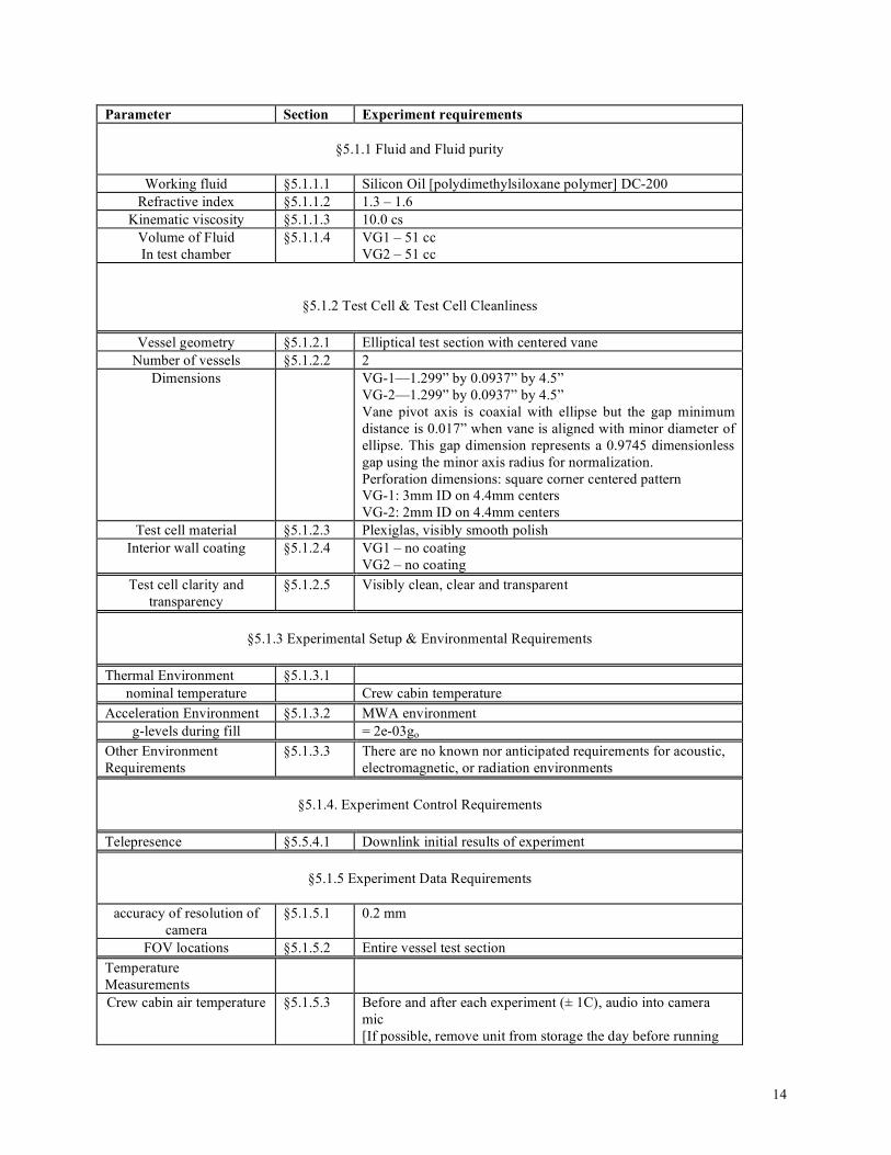
14
Parameter Section Experiment requirements
§5.1.1 Fluid and Fluid purity
Working fluid §5.1.1.1 Silicon Oil [polydimethylsiloxane polymer] DC-200 Refractive index §5.1.1.2 1.3 – 1.6
Kinematic viscosity §5.1.1.3 10.0 cs Volume of Fluid In test chamber
§5.1.1.4 VG1 – 51 cc VG2 – 51 cc
§5.1.2 Test Cell & Test Cell Cleanliness
Vessel geometry §5.1.2.1 Elliptical test section with centered vane Number of vessels §5.1.2.2 2
Dimensions VG-1—1.299” by 0.0937” by 4.5” VG-2—1.299” by 0.0937” by 4.5” Vane pivot axis is coaxial with ellipse but the gap minimum distance is 0.017” when vane is aligned with minor diameter of ellipse. This gap dimension represents a 0.9745 dimensionless gap using the minor axis radius for normalization. Perforation dimensions: square corner centered pattern VG-1: 3mm ID on 4.4mm centers VG-2: 2mm ID on 4.4mm centers
Test cell material §5.1.2.3 Plexiglas, visibly smooth polish Interior wall coating §5.1.2.4 VG1 – no coating
VG2 – no coating Test cell clarity and
transparency §5.1.2.5 Visibly clean, clear and transparent
§5.1.3 Experimental Setup & Environmental Requirements
Thermal Environment §5.1.3.1
nominal temperature Crew cabin temperature Acceleration Environment §5.1.3.2 MWA environment
g-levels during fill = 2e-03go
Other Environment Requirements
§5.1.3.3 There are no known nor anticipated requirements for acoustic, electromagnetic, or radiation environments
§5.1.4. Experiment Control Requirements
Telepresence §5.5.4.1 Downlink initial results of experiment
§5.1.5 Experiment Data Requirements
accuracy of resolution of
camera §5.1.5.1 0.2 mm
FOV locations §5.1.5.2 Entire vessel test section Temperature Measurements
Crew cabin air temperature §5.1.5.3 Before and after each experiment (± 1C), audio into camera mic [If possible, remove unit from storage the day before running

15
Table 1. Summary of Science Requirements – Vane Gap (VG1, VG2)
Parameter Section Experiment requirements experiment to allow adequate time for unit to equilibrate to the cabin temperature.]
5.2 Science requirements for the ICF experiments, Re-Flight units ICF1 and ICF2 The test cell geometry details for the ICF-1 and ICF-2 units are listed below: ICF-1 1. Test cell: tapered 75-75-30 isosceles triangle 2. Height of vertex at base 1.575” 3. Height of vertex at top 1.024” 4. All faces taper at 3.155º 5. Test cell is 5” long 6. Fluid: 20cs Silicone Oil 7. Fluid volume is 30cc: 25cc prefilled with 5cc in reserve ICF-2 1. Test cell: tapered rectangular section 2. Side faces taper only at 8.95º 3. Test cell is 5” long and 1.575” wide at base 4. Test cell is a constant 0.394” deep 5. Fluid: 2cs Silicone Oil (surfactant) 6. Fluid Volume is 19cc: 14cc prefilled with 5cc in reserve Table 2 provides a summary of the remaining science requirements for ICF-1 and ICF-2 units.
Table 2. Summary of Science Requirements – Reflight Units, Interior Corner Flow (ICF1 and ICF2)
Parameter Section Experiment requirements
§5.2.1 Fluid and Fluid purity
Working fluid §5.2.1.1 Silicon Oil [polydimethylsiloxane polymer] DC-200, with TBD Surfactant for ICF2
Refractive index §5.2.1.2 1.3 – 1.6 Kinematic viscosity §5.2.1.3 20.0 cs for ICF1, 2.0 cs for ICF2
Volume of Fluid In test chamber
§5.2.1.4 ICF1 – 30cc: 25cc prefilled with 5cc in reserve ICF2 – 19cc: 14cc prefilled with 5cc in reserve
§5.2.2 Test Cell & Test Cell Cleanliness
Vessel geometry §5.2.2.1 Triangular (ICF1) and Rectangular (ICF2) sections
Number of vessels §5.2.2.2 2 Dimensions §5.2.2.3 ICF1
Height of vertex at base 1.575” Height of vertex at top 1.024” All faces taper at 3.155º
16
Table 2. Summary of Science Requirements – Reflight Units, Interior Corner Flow (ICF1 and ICF2)
Parameter Section Experiment requirements Test cell is 5” long ICF2 Side faces taper only at 8.95º Test cell is 5” long and 1.575” wide at base Test cell is a constant 0.394” deep
test cell material §5.2.2.4 Plexiglas, visibly smooth polish Interior wall coating §5.2.2.5 None Test cell clarity and
transparency §5.2.2.6 Visibly clean, clear and transparent
Bubble Generation §5.2.2.7 Achieved as possible by crew oscillations
§5.2.3 Experimental Setup & Environmental Requirements Thermal Environment §5.2.3.1
nominal temperature Crew cabin temperature Acceleration Environment §5.2.3.2 MWA environment
g-levels during fill = 2e-03go
Other Environment Requirements
§5.2.3.3 There are no known nor anticipated requirements for acoustic, electromagnetic, or radiation environments
§5.2.4 Experiment Control Requirements
Telepresence §5.2.4.1 Downlink initial results of experiment
§5.2.5 Experiment Data Requirements
accuracy of resolution of camera
§5.2.5.1 0.25 mm
FOV locations §5.2.5.2 Entire vessel test section Temperature Measurements
§5.2.5.3
Crew cabin air temperature Before and after each experiment (± 1C), audio into camera mic [If possible, remove unit from storage the day before running experiment to allow adequate time for unit to equilibrate to the cabin temperature.]
5.3 Science requirements for the ICF experiments, New Flight Units ICF3 and ICF4 The test cell geometry details for the ICF3 and ICF4 units are listed below: ICF3

17
1. Test cell: Step taper 90º Ice Cream Cone (ice cream is flush with cone) 2. Large/Small ice cream radius: 1cm/0.95cm 3. Test cell length: 16.0cm 4. Large/Small ice cream cone section length: 9cm/7cm 5. Internal volume is 51.4cc 6. Fluid: 20cs Si Oil 7. Fluid volume in chamber, 28ml+5ml-15ml 8. Bubble diameters typically down to > 1.6mm, but as low as 0.5mm diameter acceptable. Bubble density
variable up to 50% liquid fraction ICF4
1. Test cell: Step taper 50º Ice Cream Cone (ice cream is flush with cone) 2. Large/Small ice cream radius: 0.9cm/0.855cm 3. Test cell length: 16.0cm 4. Large/Small ice cream cone section length: 9cm/7cm 5. Internal volume is 51.4cc 6. Fluid: 200cs Si Oil 7. Fluid volume in chamber, 28ml+5ml-15ml 8. Bubble diameters typically down to > 3.7mm, but as low as 1mm diameter acceptable. Bubble density
variable up to 50% liquid fraction Table 3 provides a summary of the remaining science requirements for ICF-3 and ICF-4 units.
Table 3. Summary of Science Requirements – New Units Interior Corner Flow Units (ICF3, ICF4)
Parameter Section Experiment requirements
§5.3.1 Fluid and Fluid purity
Working fluid §5.3.1.1 Silicon Oil [polydimethylsiloxane polymer] DC-200 Refractive index §5.3.1.2 1.3 – 1.6
Kinematic viscosity §5.3.1.3 20.0 cs for ICF3, 200 cs for ICF4 Volume of Fluid In test chamber
§5.3.1.4 ICF3: 28ml+5ml-15ml ICF4: 28ml+5ml-15ml
§5.3.2 Test Cell & Test Cell Cleanliness
Vessel geometry §5.3.2.1 ICF3: Stepped 90deg ice cream cone
ICF4: Stepped 50deg ice cream cone Number of vessels §5.3.2.2 2
Dimensions §5.3.2.3 ICF3 Large/small ice cream radius: 1cm/0.95cm Large/small ice cream section length: 9cm/7cm Large/small test cell height: 2.414cm/2.229cm ICF4 Large/small ice cream radius: 0.9cm/0.855cm Large/small ice cream section length: 9cm/7cm Large/small test cell height: 3.0296cm/2.878cm Transport tubing/piston size/knob thread pitch should not be selected to produce jetting flows (We < 3)
test cell material §5.3.2.4 Plexiglas, visibly smooth polish Interior wall coating §5.3.2.5 None
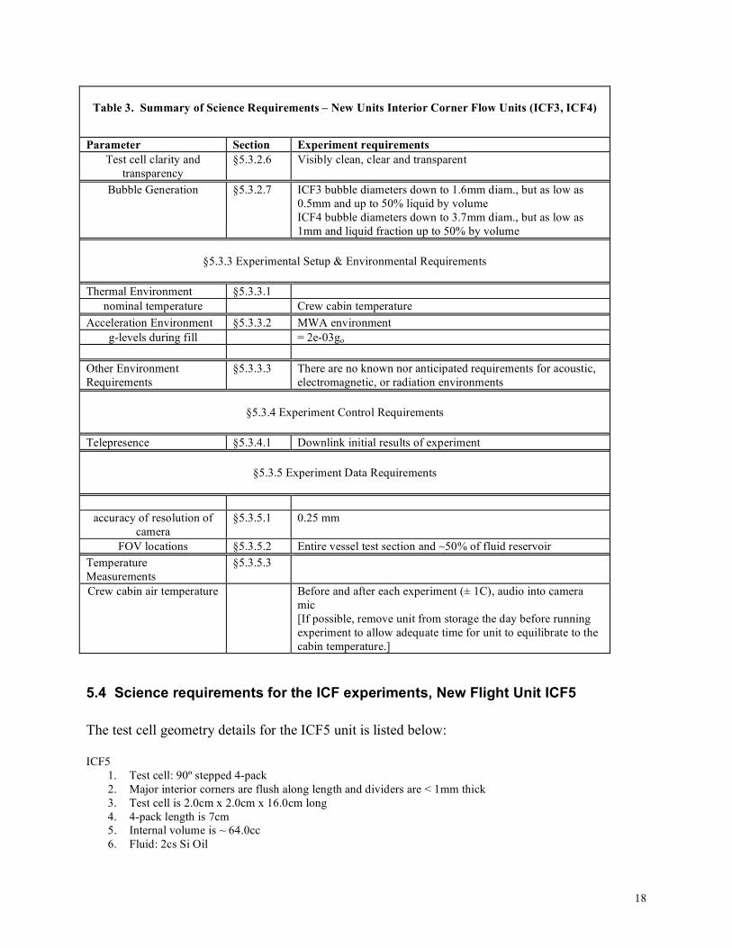
18
Table 3. Summary of Science Requirements – New Units Interior Corner Flow Units (ICF3, ICF4)
Parameter Section Experiment requirements Test cell clarity and
transparency §5.3.2.6 Visibly clean, clear and transparent
Bubble Generation §5.3.2.7 ICF3 bubble diameters down to 1.6mm diam., but as low as 0.5mm and up to 50% liquid by volume ICF4 bubble diameters down to 3.7mm diam., but as low as 1mm and liquid fraction up to 50% by volume
§5.3.3 Experimental Setup & Environmental Requirements
Thermal Environment §5.3.3.1
nominal temperature Crew cabin temperature Acceleration Environment §5.3.3.2 MWA environment
g-levels during fill = 2e-03go
Other Environment Requirements
§5.3.3.3 There are no known nor anticipated requirements for acoustic, electromagnetic, or radiation environments
§5.3.4 Experiment Control Requirements
Telepresence §5.3.4.1 Downlink initial results of experiment
§5.3.5 Experiment Data Requirements
accuracy of resolution of camera
§5.3.5.1 0.25 mm
FOV locations §5.3.5.2 Entire vessel test section and ~50% of fluid reservoir Temperature Measurements
§5.3.5.3
Crew cabin air temperature Before and after each experiment (± 1C), audio into camera mic [If possible, remove unit from storage the day before running experiment to allow adequate time for unit to equilibrate to the cabin temperature.]
5.4 Science requirements for the ICF experiments, New Flight Unit ICF5 The test cell geometry details for the ICF5 unit is listed below: ICF5
1. Test cell: 90º stepped 4-pack 2. Major interior corners are flush along length and dividers are < 1mm thick 3. Test cell is 2.0cm x 2.0cm x 16.0cm long 4. 4-pack length is 7cm 5. Internal volume is ~ 64.0cc 6. Fluid: 2cs Si Oil

19
7. Fluid volume in chamber, 36ml+5ml-15ml (read as prefilled with 36 with ability to add 5 and remove 15ml)
8. Bubble diameters typically down to 1.8mm, but as low as 0.5mm acceptable. Variable bubble density up to 50% liquid fraction
Table 4 provides a summary of the remaining science requirements for the ICF5 unit.
Table 4. Summary of Science Requirements – New Unit Interior Corner Flow Unit (ICF5)
Parameter Section Experiment requirements
§5.4.1 Fluid and Fluid purity
Working fluid §5.4.1.1 Silicon Oil [polydimethylsiloxane polymer] DC-200 Refractive index §5.4.1.2 1.3 – 1.6
Kinematic viscosity §5.4.1.3 2.0 cs for ICF5 Volume of Fluid In test chamber
§5.4.1.4 ICF5 – Fluid volume in chamber: 36ml+5ml-15ml
§5.4.2 Test Cell & Test Cell Cleanliness
Vessel geometry §5.4.2.1 ICF5: 90deg stepped 4-pack
Number of vessels §5.4.2.2 1 Dimensions §5.4.2.3 Major interior corners are flush along length and dividers are <
1mm thick Test cell is 2.0cm x 2.0cm x 16.0cm long Large/small square section length: 9cm/7cm Large/small square section face width: 2cm/~1cm 4-pack divider thickness less than or equal to 1mm Vessel must be rotated 45deg to observe profile of flow along corner with least distortion Transport tubing/piston size/knob thread pitch should not be selected to produce jetting flows (We < 3)
test cell material §5.4.2.4 Plexiglas, visibly smooth polish Interior wall coating §5.4.2.5 None Test cell clarity and
transparency §5.4.2.6 Visibly clean, clear and transparent
Bubble Generation §5.4.2.7 ICF5 bubble diameters down to 1.8mm diam., but as low as 0.5mm and up to 50% liquid by volume
§5.4.3 Experimental Setup & Environmental Requirements
Thermal Environment §5.4.3.1
nominal temperature Crew cabin temperature
Acceleration Environment §5.4.3.2 MWA environment g-levels during fill = 2e-03go
Other Environment Requirements
§5.4.3.3 There are no known nor anticipated requirements for acoustic, electromagnetic, or radiation environments

20
Table 4. Summary of Science Requirements – New Unit Interior Corner Flow Unit (ICF5)
Parameter Section Experiment requirements
§5.4.4 Experiment Control Requirements Telepresence §5.4.4.1 Downlink initial results of experiment
§5.4.5 Experiment Data Requirements
accuracy of resolution of camera
§5.4.5.1 0.25 mm
FOV locations §5.4.5.2 Entire vessel test section Temperature Measurements
§5.4.5.3
Crew cabin air temperature Before and after each experiment (± 1C), audio into camera mic [If possible, remove unit from storage the day before running experiment to allow adequate time for unit to equilibrate to the cabin temperature.]
5.5 Science requirements for the ICF experiments, New Flight Units ICF6 and ICF7 The test cell geometry details for the ICF6 and ICF7 units are listed below: ICF6
1. Test cell: Diagonal vane and square section 2. Vane thickness is < 1mm 3. Test cell is 2cm x 2cm x16cm long 4. Internal volume is ~ 64.0cc 5. Fluid: 5cs Si Oil 6. Fluid volume in chamber, 32ml±16ml 7. Bubble diameter typically down to 1.7mm, but as low as 0.5mm diameter acceptable
ICF7
1. Test cell: Diagonal vane and circular section 2. Vane thickness is < 1mm 3. test cell is 2cm diameter by 16cm long 4. Internal volume is ~ 50cc 5. Fluid: 5cs Si Oil 6. Fluid volume in chamber, 25ml±12ml 7. Note: CW to fill 8. Bubble diameter typically down to 1.7mm, but as low as 0.5mm diameter acceptable
Table 5 provides a summary of the remaining science requirements for the ICF5 unit.
Table 5. Summary of Science Requirements – New Interior Corner Flow Units (ICF6, ICF7)

21
Parameter Section Experiment requirements
§5.5.1 Fluid and Fluid purity
Working fluid §5.5.1.1 Silicon Oil [polydimethylsiloxane polymer] DC-200 Refractive index §5.5.1.2 1.3 – 1.6
Kinematic viscosity §5.5.1.3 5.0 cs for both ICF6 and ICF7 Volume of Fluid In test chamber
§5.5.1.4 ICF6: 32ml±16ml ICF7: 25ml±12ml
§5.5.2 Test Cell & Test Cell Cleanliness
Vessel geometry §5.5.2.1 ICF6: Square Section with diagonal vane
ICF7: Circular section with diagonal vane Number of vessels §5.5.2.2 2
Dimensions §5.5.2.3 ICF6: Vane thickness is < 1mm Test cell is 2cm x 2cm x16cm long ICF7: Vane thickness is < 1mm test cell is 2cm diameter by 16cm long For both: Transport tubing/piston size/knob thread pitch should not be selected to produce jetting flows (We < 3)
test cell material §5.5.2.4 Plexiglas, visibly smooth polish Interior wall coating §5.5.2.5 None Test cell clarity and
transparency §5.5.2.6 Visibly clean, clear and transparent
Bubble Generation §5.5.2.7 ICF6 and ICF7: Bubble diameter typically down to 1.7mm, but as low as 0.5mm diameter acceptable
§5.5.3 Experimental Setup & Environmental Requirements
Thermal Environment §5.5.3.1
nominal temperature Crew cabin temperature Acceleration Environment §5.5.3.2 MWA environment
g-levels during fill = 2e-03go
Other Environment Requirements
§5.5.3.3 There are no known nor anticipated requirements for acoustic, electromagnetic, or radiation environments
§5.5.4 Experiment Control Requirements
Telepresence §5.5.4.1 Downlink initial results of experiment
§5.5.5 Experiment Data Requirements
accuracy of resolution of
camera §5.5.5.1 0.25 mm
FOV locations §5.5.5.2 Entire vessel test section Temperature Measurements
§5.5.5.3
Crew cabin air temperature Before and after each experiment (± 1C), audio into camera mic

22
Table 5. Summary of Science Requirements – New Interior Corner Flow Units (ICF6, ICF7)
Parameter Section Experiment requirements [If possible, remove unit from storage the day before running experiment to allow adequate time for unit to equilibrate to the cabin temperature.]
5.6 Science requirements for the ICF experiments, New Flight Unit ICF8 The test cell geometry details for the ICF8 unit is listed below: ICF8
1. Test cell: 90º segmented conduit 2. Major interior corners are uninterrupted along length and dividers are < 1mm thick 3. Test cell is 2.0cm x 2.0cm x 16.0cm long 4. Partition/segment details are sketched in Fig. 4 (right) 5. Internal volume is ~ 64.0cc 6. Fluid: 2cs Si Oil 7. Fluid volume in chamber, 36ml+5ml-15ml (read as prefilled with 36 with ability to add 5 and remove
15ml) 8. Bubble diameters typically down to 1.8mm, but as low as 0.5mm acceptable. Variable bubble density up to
50% liquid fraction Table 6. provides a summary of the remaining science requirements for the ICF8 unit.
Table 6. Summary of Science Requirements – New Unit Interior Corner Flow Unit (ICF8)
Parameter Section Experiment requirements
§5.4.1 Fluid and Fluid purity
Working fluid §5.6.1.1 Silicon Oil [polydimethylsiloxane polymer] DC-200 Refractive index §5.6.1.2 1.3 – 1.6
Kinematic viscosity §5.6.1.3 2.0 cs for ICF5 Volume of Fluid In test chamber
§5.6.1.4 ICF5 – Fluid volume in chamber: 36ml+5ml-15ml
§5.6.2 Test Cell & Test Cell Cleanliness
Vessel geometry §5.6.2.1 ICF5: 90º segmented conduit
Number of vessels §5.6.2.2 1 Dimensions §5.6.2.3 Major interior corners are uninterrupted along length and
dividers are < 1mm thick Test cell is 2.0cm x 2.0cm x 16.0cm long Partition/segment details are sketched in Fig. 4 (right) Vessel must be rotated 45deg to observe profile of flow along corner with least distortion Transport tubing/piston size/knob thread pitch should not be selected to produce jetting flows (We < 3)

23
Table 6. Summary of Science Requirements – New Unit Interior Corner Flow Unit (ICF8)
Parameter Section Experiment requirements test cell material §5.6.2.4 Plexiglas, visibly smooth polish
Interior wall coating §5.6.2.5 None Test cell clarity and
transparency §5.6.2.6 Visibly clean, clear and transparent
Bubble Generation §5.6.2.7 ICF8 bubble diameters down to 1.8mm diam., but as low as 0.5mm and up to 50% liquid by volume
§5.6.3 Experimental Setup & Environmental Requirements
Thermal Environment §5.6.3.1
nominal temperature Crew cabin temperature
Acceleration Environment §5.6.3.2 MWA environment g-levels during fill = 2e-03go
Other Environment Requirements
§5.6.3.3 There are no known nor anticipated requirements for acoustic, electromagnetic, or radiation environments
§5.6.4 Experiment Control Requirements
Telepresence §5.6.4.1 Downlink initial results of experiment
§5.6.5 Experiment Data Requirements
accuracy of resolution of camera
§5.6.5.1 0.25 mm
FOV locations §5.6.5.2 Entire vessel test section Temperature Measurements
§5.6.5.3
Crew cabin air temperature Before and after each experiment (± 1C), audio into camera mic [If possible, remove unit from storage the day before running experiment to allow adequate time for unit to equilibrate to the cabin temperature.]
6. Experimental Test Plan and Test Matrix
6.1 Introduction

24
The general set-up, camera alignment, focus, lighting, fluid fill, expected fluid response times, and experiment operation times are designed to be similar to enhance the routine for performing CFE-2 on orbit. The most critical experimental steps are listed here followed by representative test matrices for the different CFE-2 vessels.
6.2 Experimental Test Plan
6.2.1 Experimental Test Plan for the VG experiments General Notes, applicable to all tests: Two VG units are needed for the experiment to identify the impact of vane geometry and vane porosity on the critical wetting phenomena. The two units are in every way identical except for the perforated vane type, CFE-VG1 36.5% open, CFE-VG2 16.2% open. The original CFE-1 VG vessels will be refurbished for this purpose. The newly constructed vanes must have two ‘edges’ as described in Section 2.1 (shown in Fig. 1). The general experiment procedures for both vessels are identical and include:
1. A prescribed amount of liquid is dispensed from a reservoir into an elliptic cross-sectioned cylindrical container in the low-g environment.
2. The vane is then indexed clockwise through one complete revolution (360º) in approximately 32 prescribed degree increments. The response of the fluid interface is recorded by video imaging.
3. At each increment of vane rotation, time (approximately 30 s) is allowed for the interface to establish equilibrium. Small perturbations (by hand, i.e. finger taps) to the container may be employed to assure local equilibrium is established. At or near critical vane angles significant time (~15min) is allotted for the reorientation.
4. The vane rotation procedure is then reversed (counter clockwise) with identical increments and perturbations for the equilibrium surfaces.
5. The clockwise/counter clockwise rotation may be repeated indefinitely—three times is desired. (The perforations are specified large enough that liquid remaining in the perforations after each critical wetting event may be dislodged by crew perturbations.)
Caution Notes, applicable to all: Special care must be taken during conduct of the experiments not to disturb the interface to the point the vane is unduly wetted or the surface breaks-up and forms bubbles.
6.2.2 Experimental Test Plan for the ICF experiments The 8 CFE-2 ICF units are:
1. ICF1 (re-flight, equilateral triangular section, parabolic taper)

25
2. ICF2 (re-flight, rectangular section, linear taper) 3. ICF3 (new, stepped ice-cream cone taper, large angle 90deg) 4. ICF4 (new, stepped ice-cream cone taper, small angle 50deg) 5. ICF5 (new, graded porosity container, ‘4-pack’) 6. ICF6 (new, square section, tapered vane) 7. ICF7 (new, circular cylindrical section, tapered vane) 8. ICF8 (new, tapered pore structure/network)
General Notes, applicable to all tests: Once the required test vessel, video camera, and lighting conditions are established, the test sequences for the ICF containers are similar and follow the general procedure: The test vessel chambers are prefilled with a prescribed volume of fluid to reduce over-pressurization during liquid volume adjustments between experiments.
1. The fluid is positioned at the base of the container by crew-induced centrifugal accelerations and the test cell is rapidly restored to the ISS work bench (MWA). This and the processes to follow are captured on video.
2. After the initial imbibition is complete (fluid shifts to ‘top’ of container and equilibrates), the test is repeated twice either by repeating the centrifugal method or by employing valve operations draining the fluid from the top and re-filling it from the base.
3. The apparatus should then be used to repeat the tests performed in (2), but allowing for a by-pass tube connecting the base of the tapered container with the top of the container. The tests conducted with such a by-pass line open simulate certain applications in microgravity fluids management systems and provide a unique comparison opportunity for the theory as fluid imbibes within the container as well as is drawn through the bypass line.
4. The experiments in 2 and 3 above are then repeated following the generation of a variety of bubbles in the liquid. For ICF1 and 2, with the prescribed amount of fluid in the test chamber, bubbles can be generated in the chamber by ‘shaking’ the container. The container should be replaced for video photography, and the passive imbibition, phase times with several tests performed for a variety of bubble sizes, densities, and distributions. For ICF3 through ICF8, a bubble generation scheme should be employed to more effectively generate bubble distributions with bubble sizes typically 1.5 to 2mm diameter and larger, but as low as 0.5mm in diameter is of interest. Bubble densities between 100 and 50% liquid fraction are desired.
Digitized video images will be compared to theoretical and numerical predictions. ICF1 and ICF2 are expected to be refurbished for re-flights to satisfy these requirements with the added capability to more significantly vary the fluid volume in ICF-1 and to add a foaming surfactant to ICF2. ICF-3 through ICF 8 require similar, but new hardware. Caution Notes, applicable to all:

26
After re/introduction of the fluid into the test chamber, sufficient time (up to approximately 15minutes) must be allowed for video photography of the redistribution of the fluid throughout the chamber. It is important to ensure the camera and front face of the test vessel are orthogonal.
6.3 Test Matrix
6.3.1 Test Matrix for the VG experiments Table 7. Vane Gap (VG) Experimental Test Matrix Test Vessel Type of test No. of test points Vessel surface
condition VG1 Initial steady state
after fill 1 angle test point Dry
Clockwise (CW) rotation
20 angle test points Dry
CW rotation 20 angle test points Wet CW rotation (repeat) 20 angle test points Wet Counterclockwise
(CCW) rotation 20 angle test points Wet
VG2 Initial steady state after fill
1 angle test point Dry
Clockwise (CW) rotation
20 angle test points Dry
CW rotation 20 angle test points Wet CW rotation (repeat) 20 angle test points Wet Counterclockwise
(CCW) rotation 20 angle test points Wet
6.3.2 Test Matrix for the ICF experiments Table 8. Interior Corner Flow (ICF) Experimental Test Matrix (ICF1 through ICF8) Test Vessel Type of test No. of test points Test cell volume (ml) ICF1 Initial transient flow 1 test point 25ml Relocate/ repeat (2x) 2 test points 25ml Relocate/repeat (2x) 2 test points 30ml Relocate/repeat (2x) 2 test points 20ml Bubble separation
tests (1-5mm bubbles) 4 test points 15ml
ICF2 Initial transient flow 1 test point 14ml Relocate/ repeat (2x) 2 test points 14ml Relocate/repeat (2x) 2 test points 19ml

27
Relocate/repeat (2x) 2 test points 10ml Bubble separation
tests (1-5mm bubbles) 4 test points 10ml
ICF3 Initial transient flow 1 test point 28ml Relocate/ repeat (2x) 2 test points 28ml Relocate/repeat (2x) 2 test points 33ml Relocate/repeat (2x) 2 test points 13ml Bubble separation
tests (1-5mm bubbles) 4 test points 13ml
ICF4 Initial transient flow 1 test point 28ml Relocate/ repeat (2x) 2 test points 28ml Relocate/repeat (2x) 2 test points 33ml Relocate/repeat (2x) 2 test points 13ml Bubble separation
tests (1-5mm bubbles) 4 test points 13ml
ICF5 Initial transient flow 1 test point 36ml Relocate/ repeat (2x) 2 test points 36ml Relocate/repeat (2x) 2 test points 41ml Relocate/repeat (2x) 2 test points 21ml Bubble separation
tests (1-5mm bubbles) 4 test points 21ml
ICF6 Initial transient flow 1 test point 32ml Relocate/ repeat (2x) 2 test points 32ml Relocate/repeat (2x) 2 test points 48ml Relocate/repeat (2x) 2 test points 16ml Bubble separation
tests (1-5mm bubbles) 4 test points 16ml
ICF7 Initial transient flow 1 test point 25ml Relocate/ repeat (2x) 2 test points 25ml Relocate/repeat (2x) 2 test points 37ml Relocate/repeat (2x) 2 test points 13ml Bubble separation
tests (1-5mm bubbles) 4 test points 13ml
ICF8 Initial transient flow 1 test point 36ml Relocate/ repeat (2x) 2 test points 36ml Relocate/repeat (2x) 2 test points 41ml Relocate/repeat (2x) 2 test points 21ml Bubble separation
tests (1-5mm bubbles) 4 test points 21ml

28
7 Success Criteria for CFE-2
7.1 Definition of Nominal, Minimal, and Maximum Success Criteria Three mission scenarios are assumed here: (1) a nominal mission is where all originally proposed procedures are completed, (2) a minimum science/minimum success scenario is considered where minimal procedures are conducted from which at least one scientific observation can be made, and a (3) maximum (or extra) science scenario where additional tests are performed if additional crew time above that required for the nominal case were available.
7.2 Success Criteria for the Vane Gap (VG) experiments
7.2.1 Nominal Mission Scenario: The nominal mission scenario is one where all originally proposed procedures are performed and photographed. For the VG vessels this requires: VG Vessels 1 and 2 procedures are identical
1. Set-up of vessel and lighting (~30-60min) 2. The filling of the elliptical cylindrical test chamber. (~10-15min) 3. Rotation of the vane 360º CW and CCW. (~40-60min) 4. Two repeat rotations of the vane (40-60min) 5. 720º continuous rotation both CW and CCW (10min) 6. Return of flight video tapes.
7.2.2 Minimal Mission Scenario: The minimal mission scenario is one where only one complete 360º CW and CCW rotation of the vane is completed. For the VG Vessels this could entail: VG Vessels 1 and 2 (VG1 higher priority)
1. Set-up of vessel and lighting (~30-60min) 2. The filling of the elliptical cylindrical test chamber. (~10-15min) 3. Rotation of the vane 360deg CW and CCW. (~40-60min) 4. Downlink of video (minimum) or return of flight video tapes.
7.2.3 Extra Mission Scenario:

29
The extra mission scenario is one where additional time and resources (video tape) are available to perform tests that can yield quantitative science or engineering information in addition to that gained from the successful performance of the nominal mission. [All experiment procedures for VG can be performed in ‘Saturday Science Mode’ aboard the ISS.] Extra tests are valued, and could use either VG vessel (or both). Results from the nominal onboard testing would play a significant role in identifying a priority for extra science should such an opportunity arise. VG Vessels VG1 and VG2
1. Repeat the nominal mission procedures. Statistical results are possible for this experiment. (~40-120min)
2. Rotate the vane at several steady rotation rates through 720 degrees CW and CCW. Rotation rates should start slow and increase incrementally up to approximately 1Hz.
3. Indexed rotation through 360deg at prescribed increments with increased angle resolution, CW and CCW.
4. Time elapsed photography of the interface at a slightly subcritical wetting condition.
5. Rotate Vane to critical angle then fill container (P. Concus inspired). 6. Others could be specified. 7. Return of flight video tapes.
7.3 Success Criteria for the Interior Corner Flow (ICF) experiments
7.3.1 Nominal Mission Scenario: The nominal mission scenario is one where all originally proposed procedures are performed and photographed. For the ICF vessels this requires: ICF1 through ICF8 procedures and tests are identical
1. Set-up of vessel and lighting (~30min) 2. The first orientation of test fluid and observation of capillary driven flow from the base to
top of the container. (~15min) 3. Repeated repositioning and/or draining and refilling of the test chamber with and without
bypass tube. (~40min) 4. Conduct and repeat Bubble separation tests for three bubble densities. (~90min) 5. Return of flight video tapes.
7.3.2 Minimal Mission Scenario: The minimal mission scenario is one where only three ICF containers can be tested. For ICF this could entail: ICF3 and ICF4:

30
1. Set-up of vessel and lighting (~30-60min) 2. The filling of test chamber and observation of capillary driven flow from the base to top
of the container. (~15min) 3. Repeated repositioning and/or draining and refilling of the test chamber with (once) and
without (once) bypass tube open. (40min) 4. Conduct and repeat Bubble separation tests for three bubble densities. (~90min) 5. Downlink of video data (minimum) or return of flight video tapes.
7.3.3 Extra Mission Scenario: All CFE-ICF experiment procedures can be performed in ‘Saturday Science Mode’ aboard the ISS. Several possible extra tests are valued, and could use either ICF vessel (or both). Result from onboard testing would play a significant role in identifying a priority for extra science should such an opportunity arise. ICF Vessels ICF1 through ICF8
1. Repeat the nominal mission procedures. Statistical results are possible for this experiment. (~30-40min)
2. Wider variation in fill volumes. 3. Wider variation in bubble size and density. 4. Time elapsed photography of ISS g-jitter on bubbles formed. 5. Others could be specified such as more complex phase separation tests. 6. Return of flight video tapes.
8. Ground Test Experimental Plan
8.1 Rationale
8.1.1 Rationale for ground tests to support the VG experiments A series of drop tower tests (up to 20 drops, 2.2s tower GRC) performed using the VG engineering units would demonstrate the extent drop towers can be used to identify such critical wetting phenomena. Such tests are likely to guide the crew procedures in efficiently establishing appropriate near critical conditions, setting the increment of the vane dial, and optimizing the crew procedures. These tests would reduce crew time by honing in on the critical phenomena faster and provide a preliminary comparison for theoretical predictions.
8.1.2 Rationale for ground tests to support the ICF experiments A series of drop tower tests (up to 30 drops, 2.2s tower GRC) should be performed to determine idealized wetting rates for the containers. Such results will help guide development of the crew
31
procedure, but will also produce new science. Further ground studies employing elements of the ICF geometries can be tested to investigate the unique and relevant low-g flow scenarios for which analytic solutions are currently being pursued.
8.2 Ground Test Plan A complete investigation for VG and ICF can benefit from a number of simple drop tower tests using the engineering CFE units. In several cases, new science can be gained increasing the breadth or impact of the flight results and enhancing their publication potential. In some cases, 1-g tests will be necessary to develop the image analysis tools necessary for (near) real time evaluation of the flight results to guide subsequent tests with the same vessel or a vessel to follow.
8.2.1 Ground Test Plan to support VG experiments Drop tower tests will be performed using VG engineering units for a variety of vane angles. The approximate range of the critical wetting phenomena will be identified and used to specify the vane increments for the flight experiment. There is not sufficient time to establish equilibrium in such experiments, but gross wet/no wet conditions may be identified. It is also possible to study specific flow rates for sub-critical angles where corner wetting is certain. Low viscosity inertial-capillary flow in such geometries may be investigated providing a complete story for publication of the investigation.
8.2.2 Ground Test Plan to support ICF experiments The specific drop tower tests performed for the ICF units will employ low viscosity fluids partly filling the test chambers and dropping them in the tower, recording the transient interface behavior on video. The tests serve as inertially dominated counterparts to the viscous-dominated flight experiments and benefit from a more idealized initial condition which cannot be easily achieved on orbit. The data will be compared to the flight results during the long duration flows. Further and important experiments will be conducted by inverting the test cells and dropping vessels. The transient capillary flows that result may be used to establish the correct boundary conditions for the flows, which cannot be verified without such tests. General Notes All drop tower experiments for VG and ICF should be conducted at NASA GRC’s 2.2s drop tower facility by the PI team.
9. References
32
Anantharaju, N., M.V. Panchagnula, S. Vedantam, S. Neti, S. Tatic-Lucic, Effect of Three-Phase Contact Line Topology on Dynamic Contact Angles on Heterogeneous SurfacesLangmuir 2007, 23, 11673-11676. Ayyaswamy, P.S., Catton, I., Edwards, D.K., (1974) Capillary flow in Triangular Groves, ASME Journal of Applied Mechanics, Vol. 41, 332-336. Brakke K.A. (2003) Surface Evolver program, the code and manual are available at: http://www.susqu.edu/facstaff/b/brakke/. Chato, D.J., T.A. Martin (1997) Vented Tank Resupply Experiment—Flight Test Results, 33rd AIAA/ASME/SAE/ASEE Jnt. Propulsion Conf., AIAA-97-2815 July 6-9, Seattle. Chen, Y., Collicott, S.H. (2002) Investigation of Wetting Behavior of a Vane-Wall Gap in Propellant Tanks, 40th AIAA Joint Prop. Conf., AIAA-2002-3986, Indianapolis, IN. July. Chen, Y., Weislogel, M. M., Nardin, C. (2006) Capillary-driven flows along rounded interior corners, J. Fluid Mech. 566:235-271. Chen, Y., R. Jenson, M. Weislogel, S. Collicott (2008a) Capillary Wetting Analysis of the CFE-Vane Gap Geometry, AIAA-2008-0817, 46th AIAA Aerospace Sci. Meeting and Exhibit, Reno, Nevada, Jan. 7-10, 2008. Chen, Y., D. Bolleddula, N. Tavan, M.M. Weislogel (2008b) Capillary Flow in Complex Geometries, Drop Tower Days, Beijing, Oct. (in prep. for Microgravity Science and Technology) Collicott, S.H., Weislogel, M.M., Computation of Capillary Instabilities Using Surface Evolver, AIAA J., Vol. 42, No. 2, pp. 289-295, Feb. 2004. Collicott, S.H. (2008) Private Communication, Critical wetting experiments were unsuccessful aboard the NASA KC-135 aircraft by as part of an undergraduate student campaign research project. Columbus, R.L., Palmer, H.J., Architectured Fluid Management of Biological Liquids, Clinical Chemistry, Vol. 33, No. 9, 1987, pp 1531-1537 Concus, P., Finn, R. (1990) Capillary Surface in Microgravity, in Low-Gravity Fluid Dynamics and Transport Phemomena, Vol. 130, Progress in Astronautics and Aero., AIAA, pp. 183-204 Concus, P. Finn, R., Weislogel, M. (2000) Measurement of Critical Contact Angle in a Microgravity Experiment, Experiments in Fluids, 28:3, 197-205. Concus, P. Finn, R., Weislogel, M. (1999) Capillary Surfaces in an Exotic Container: Results from Space Experiments, J. Fluid Mech. 394:119-135, October.

33
Concus, P., Finn, R. (1969) On the Behavior of a Capillary Free Surface in a Wedge, Proc. Nat. Acad. Sci. U.S.A., 63, No. 2, June, pp. 292-299. Dong M., Chatzis, I. (1995) The imbibition and flow of a wetting liquid along the corners of a square capillary tube, J. Colloid and Int. Sci., Vol. 172, Issue 2, June, 278-288. Dyson, D.C., Contact line stability at edges: Comments on Gibbs's inequalities, Physics of Fluids, 31(2):229--232, February 1988. Finn, R. (1986) Equilibrium Capillary Surfaces, Springer-Verlag, New York. Gauglitz, P.A., Radke, C.J., The Dynamics of Liquid Film Breakup in Constricted Cylindrical Capillaries, Chem. Eng. Sci., 43:1457, 1988 Jaekle, D.E., Jr., Propellant Management Device Conceptual design and Analysis: Vanes, AIAA/SAE/ASME/ASEE 27th Joint Propulsion Conference, AIAA-91-2172, June 24-26, 1991, Sacramento, CA Jaekle, D.E., Jr., Propellant Management Device Conceptual Design and Analysis: Vanes, AIAA-91-2172, 1991. Jaekle, D.E., Jr., Propellant Management Device Conceptual Design and Analysis: Sponges, AIAA-93-1970, 1993. Jaekle, D.E., Jr., Propellant Management Device Conceptual Design and Analysis: Traps & Troughs, AIAA-95-2531, 1995. Jaekle, D.E., Jr., Propellant Management Device Conceptual Design and Analysis: Galleries”, AIAA-97-2811, 1997. Kovscek, A.R., Radke, C.J. Gas bubble snap-off under pressure driven flow in constricted noncircular capillaries, Colloids and Surfaces A, 117, 56-76, 1996. Langbein, D. (2002) Capillary Surfaces: Shape-Stability-Dynamics, in Particular under Weightlessness, Springer Tracts in Modern Physics 178. Lenormand, R., Zarcone, C., Sarr, A. (1983) Mechanisms of displacement of one fluid by another in a network of capillary ducts, J. Fluid Mech., Vol 135, pp 337-353. Myshkis, A.D., Babskii V.G., Kopachevskii N.D., Slobozhanin, L.A., Tyuptsov, A.D. (1987) Low-Gravity Fluid Mechanics, Springer-Verlag, New York. Paterson, A., Fermigier, M., Jenffer, P., Limat, L., Wetting on heterogeneous surfaces: experiments in an imperfect Hele-Shaw cell, Physical Review E, 51: 2 pp 1291-8, Feb. 1995.

34
Ransohoff, T.C., Radke, C.J. (1988) Laminar Flow of a Wetting Liquid along Corners of a predominately Gas-Occupied Noncircular pore", J. Colloid and Int. Sci., Vol. 121, No.2, Feb. 1988, p 392. Romero L.A, F.G. Yost (1996) Flow in an Open Channel Capillary, J. Fluid Mech., 322:109-129. Weislogel, M.M. (2003) Some Analytical Tools for Fluids Management in Space: Isothermal Capillary Flows Along Interior Corners, Adv. Space Res., Vol. 32, No. 2, pp. 163-170. Weislogel, M.M. and S. Lichter (1998) Capillary Flow in Interior Corners, J. Fluid Mech., 373:349-378, November. Weislogel, M.M. (2001a) Capillary Flow in Containers of Polygonal Section, AIAA J., 39(12), 2320-2326. Weislogel M.M. (2001b), Capillary Flow in Interior Corners: the Infinite Corner, Phys. of Fluids, 13(11):3101-3107, November. Weislogel, M.M., R.M. Jenson, Y. Chen, S.H. Collicott, and S. Williams, Geometry Pumping on Spacecraft: The CFE-Vane Gap Experiments on ISS, 3rd International Symposium on Physical Sciences in Space (ISPS) 2007, Abstracts A11-2, pp. 443-444, Nara Japan, Oct. 22-26. (submitted for publication in the Japan Society of Microgravity Application Journal (JASMA)) Weislogel, M., R. Jenson, D. Bolleddula, Capillary Driven Flows in Weakly 3-Dimensional Polygonal Containers, AIAA-2007-748, 45th AIAA Aerospace Sci. Meeting and Exhibit, Reno, Nevada, Jan. 8-11, 2007. Weislogel, M.M., R.M. Jenson, Y. Chen, S.H. Collicott, and S. Williams (2007) Geometry Pumping on Spacecraft: The CFE-Vane Gap Experiments on ISS, Japan Society of Microgravity Application Journal on Physical Sciences in Space (accepted) Weislogel, M.M., Some Analytical Tools for Fluids Management in Space: Isothermal Capillary Flows Along Interior Corners, Adv. Space Res., Vol. 32, No. 2, pp. 163-170, 2003.