schmid boas 1
TRANSCRIPT

8/9/2019 Schmid Boas 1
http://slidepdf.com/reader/full/schmid-boas-1 1/28
PLASTICITY OF
CRYSTALSWITH SPECIAL REFERENCE TO METALS
BY
DR. E. SCHMID
AND
DR.-ING. W. BOAS
A translation from the German by F. A. Hughes & Co., Limited.
of
" KRISTALLPLASTIZITAET
mit besonderer BerUcksichtigung der Metalle."
1935
LONDON
F. A. HUGHES & CO. LIMITED
BATH HOUSE, PICCADILLY, W.I
1950
8/9/2019 Schmid Boas 1
http://slidepdf.com/reader/full/schmid-boas-1 2/28
English t!'anslation copyright:
Sole licence-holders:
MAGNESIUM ELEKTRON LD'IITED
All rights reserved.
Printed in Great B"itain
by Richard Clay and Company, Lld., Bungay, St'JJolk,
and published by
F. A. HUGHES & CO. LIMITED
Balh House, 82 Piccadill.~, London, W.l
1950
8/9/2019 Schmid Boas 1
http://slidepdf.com/reader/full/schmid-boas-1 3/28
TRANSLATORS' PREFACE
When Schmid and Boas decided to publish in book form the
results of their widespread investigations into the mechanism of the
deformation of metals, they rendered a great service to all those in
science and industry interested in studying the same problem.
This book, with its lucid exposition and wide range, is cited as thefirst reference in innumerable metallurgical papers, and became a
classic within a year or two of its pu blication.
The major problems resulting from the complex deformation
behaviour of magnesium led the scientists concerned with that metal
to welcome the concentrated knowledge on the subject contained
in Schmid and Boas' publication.
In accordance with our resolve to make available to the magne-
sium and other industries new publications of value to their research
and development, we decided to add the translation of this book to
our previous publications of Beck and of Bulian and Fahrenhorst.
Since the appearance of Schmid and Boas' book there has been a
great development in the field treated, and many aspects of strength
and plasticity have changed considerably. However, no text-book has appeared that could replace Schmid-Boas in every respect,
and it has remained as indispensable to the research worker as it
was when first published. Information about the most important
changes that have taken place in the meantime can be obtained
from a less detailed treatment of the subject in the book An Intro-
duction to the Physics of Metals and Alloys, by Dr. W. Boas (Melbourne
University Press), while the structural aspects of plastic deforma-
tion are dealt with in C. S. Barrett's book, Structure of Metals
(McGraw-Hill Book Company, Inc.).
The translation of K ristallplastizitaet has taken a long time, but we
believe its contents to be of great value, and it is our hope that the pro-
vision of an English text will materially assist all those researchers
who are interested in the deformation and plasticity of crystals.
In conclusion we wish to express our thanks to Dr. W. H. Taylor,
Dr. E. Orowan and Mr. R. W. K. Honeycombe of the Cavendish
Laboratory, Cambridge, for revising the translation and aiding us
to prepare it for the press, and to Mr. L. H. Tripp (the translator),
who has carried the main burden.
F. A. HUCHES & Co. LIMITED.
January 1950.,.
8/9/2019 Schmid Boas 1
http://slidepdf.com/reader/full/schmid-boas-1 4/28
VI Translators' Preface
When the German edition was published D1".E. Schmid was Pm-
fess01' of Physics at F1"ibourg University (Switzerland) and foreign
correspondent of the ]{aise1" Wilhelm-Gesellschaft,. he is at p1"esentwith
the Metallgesellschaft A.G., Frankfort-on-Main. Dr. W. Boas was at
the same university, and is now Chief of Division of Tribophysic8,
Commonwealth Scientific and Industrial Resea1"ch 01"ganization,
J1 elboume.
8/9/2019 Schmid Boas 1
http://slidepdf.com/reader/full/schmid-boas-1 5/28
FOREWORD
Plasticity is that propcrty of solids by virtue of which thcy change
their shape permanently under the influence of external forces.
Although this property has been exploited since the earliest days
of human history-an exploitation which, thanks to modern tech-
nical methods, has now reached a very high level of perfection-
and although unceasing efforts have been made to obtain a clear
picture and a scientific explanation of the processes involved in the
phenomenon of deformation, so far neither a full description nor an
entirely adequate theoretical interpretation has been possible.
In the present work, which is based on lectures which I delivered
in 1930-31 at the Technical High School in Berlin, we describe what
is known about the plastic behaviour of a specially important class
of solids-crystals. Since the deformation of crystal aggregates is
mainly governed by the deformation of the individual grain, the
latter provides the foundation for our knowledge of the plasticity
of crystalline materials in gcneral. In the last twenty years we
have learnt a great deal about crystal plasticity, in the first place,
owing to the development of methods for growing crystals, whichhave enormously increased the experimental material available,
and secondly, as a result of the application of X-ray diffraction
methods to the investigation of solids.
This book is addressed to a large circle of readers. Thc cxperi-
mental data which it presents in classified form, and which it
attempts to interprct, should assist the physicist to evolve a theory
of plasticity. It brings to the notice of the crystallographer and
mineralogist those researches into metal crystals which have for
their particular object the dynamics of crystal deformation. The
geologist will discover, in the development of textures in cast and
wrought metals, analogies with similar phenomena in his own field
of enquiry, and he should therefore find our tentative explanations
instructive. Workers in the field of metals research and technologywill find in this book the crystallographic and physical principles
underlying the plastic behaviour of their material, and they will be
shown by examples how 0UI' knowledge of the polycrystalline state
can be both increased and applied. Technologist and designer will
become familiar with that mass of data from which the technological
characteristics of metals are derived. In this way the fundamental
significance of the constants employed, and, in particular, theVII
8/9/2019 Schmid Boas 1
http://slidepdf.com/reader/full/schmid-boas-1 6/28
VJll Foreword
possibility of changing them during operations, will be made clear.
Last but not least, it is hoped that all those who themselves are
studying the plasticity of crystall ine materials will be helped by
this book in their choice of experimental technique and methods of
research.
I wish to express my gratitude to Mr. M. Polanyi, who introduceJ
me to this subject many years ago, who has since been of great
assistance to me, and to whose inspiration this book is due. Sincere
thanks are also extended to all my collaborators during the happy
years of work at the Kaiser Wilhelm Institute for Fibre Chemistry
and Metal Research in Berlin, and especially to Messrs. S. Wasser-
mann, W. Boas (co-author of this book), ''\T. Fahrenhorst and
G. Siebel (Bitterfeld). I am also grateful to the Notgemeinschaft
Jer Deutschen Wissenschaft for their continued assistance.
I should like to thank numerous colleagues for permission to
reproduce illustrations and diagrams from their works; and I am
also indebted to the publishers for their co-operation, and for the
very helpful way in which they have met my wishes.
Fribourg, Switzerland.
Jamtary 1935.
ERrOR SOHMlD
8/9/2019 Schmid Boas 1
http://slidepdf.com/reader/full/schmid-boas-1 7/28
CHAP.
CONTENTS
TRAKSLATORS' PREFACE
FOREWORD
PACK
\'11
I~TRODUCTION xy
1. Crystalline and Amorphous Solids XVI
I. SOME FUNDAMENTALS OF CRYSTALLOGRAPIIY 1
2. Lattice Rtructul'e of Crystals 1
3. Crystal Symmetry 1
4. The Crystallographic Repr03entation of Plane3 and Directions 4
5. Crystal Projec:tion 8
G . Simple Crystallographic Theorems 11
Il. ELASTICITY OF CRYSTALS 14
7. Hooke's Law 14
8. Simpl ification of the Equations of" Hooke's Lawas a Consequence of Cryst.tl Symmetry 15
9. Cauchy's Relations 17
10. Determination of the Elastic Parameter" 20
Ill. PROD CTION OF CRYSTALS . 22
11. Recrystallization after Crit icaI
Plastic Deformation 2212. Crystal Production by Grain Growth . 26
13. Crystallization in the Crucible 27
14. Production of Crystals by Drawing from the Melt 31
15. Crystal Growth by Precipitation from Vapour 32
16. Crystal Growth by Electrolytic Deposition . 33
1'-. DETER)IIXATION OF THE ORIENTATION OF CRYSTALS 34
17. Symmetry of Percussion-figures. Im-e"tigation of Light Reflected frOIn Crystal Surface" 34
18. The Diffraction of X-rays by Crystal Lattice" 35
19. Basic Formulm 37
20. Oblique Photographs 40
21. Layer-line Diagrams 41
22. X-Ray Goniometer 44
23. Examples of the Determination of Orientation by
the Rotating-crystal Method 4424. Example of the Determination of Orientation byLaue Photographs 48
V. GEO)IETRY OF THE :vrECHANIS)IS OF CRYSTAL DEFORMA-
TI ON 55
25. Model of Gliding 55
26. Geometrical Treatment of Simple Glide 57
27. Transformation of Indices in Glide 63
28. Double Glide 64
ix
•
8/9/2019 Schmid Boas 1
http://slidepdf.com/reader/full/schmid-boas-1 8/28
xCIIAP.
ContentsPAGE
29. Formation of Spurious Glide Bands 68
30. )fodel of Twinning 69
31. Geometrical Treatment of )1echanical Twinning 71
32. Possibility of Twinning and Transformation of Indices. 74
33. Ernpirical Crystallographic Rules 75
\"1. PLASTICITY AND STRENGTH 01' METAL CRYSTALS 77
34. Determination of the Elements of Gliding 77
35. The Glide Elements of Metal Crystals 84
36. )Ianifestations of Glide 86
37. Determination of Twinning Elements. 90
38. The Twinning Elements o f Metal Crystals 94
39. Operation of 2Vlechanical Twinning 96
40. Initiation of Glide in the Tensile Test (Yield Point).The Critical Shear Stress Law 103
41. Torsion of Crystals 109
42. Critical Shear Stress of Metal Crystals 112
43. The Progress of Glide. The Yield-Stress Curve 118
44. Termination of Glide. 126
45. The Start of Glide in Alloyed )'[etal Crystals 133
46. Progress of Glide and Fracture in Alloy Crystals 139
47. The Influence of Temperature and Speed upon theStart of Glide 145
48. Progress and Termination of Gli(le in Relation toTemperature and Spee(l 149
49. Crystal Recovery 158
.50. Glide Regarded as the Superimposition of Hecoveryupon an Athermal Fundamental Process 161
51. The Condition of Twinning 162
52. )'[utual Influence of Twinning and Glide 164
53. Conditions Co\-ering Brittle Fracture. Sohncke's~ormal Stress Law 169
54. Influence of Previous Deformation upon theCritical Normal Stress. "Strain Strengthening" 175
55. After-effect and Hysteresis. Bauschinger Effect. 179
56. Crystallographic Deformation and Cleavage Pro-cesses under Cyclic Stressing . 181
57. Phenomena of Hardening under Cyclic Stressing. 185
58. Anisotropy of the Physical Properties of Metal
Crystals 1\)259. Cold ""ork and the Crystal Lattice 195
60. Cold ''''ork and Physical and Chemical Propel,ties 201
61. The Nature of the Recrystallization Kuclei . 208
62. Velocity of Growth of the Newly Formed Grains 214
63. Orientation of the ~ewly Formed Grains 218
64. Grain Growth 220
65. Reversion to the Original Properties by HeatTreatment 221

8/9/2019 Schmid Boas 1
http://slidepdf.com/reader/full/schmid-boas-1 9/28
CHAP.
Contents xiPAGE
VII. PLASTICITY AND STRENGTHOF IONIC CRYSTALS 227
66. Gliding and Twinning Elements 227
67. Initiation of Glide. Shear St1'ess Law 231
68. Further Course of the Glide Process 239
69. Fracture of Crystals. Sohncke's ~ ormal StressLaw 241
70. Hardness 248
71. Enect of Cold '''lorking on Yarious Properties.Hecovery and Recrystallization 252
72. The Effect of a Solvent on the :\Iechanical Proper-ties. Joffe Effect. 257
YIII. THEORIESOF CRYSTALPLASTICITYANDCRYSTALSTRENGTH 265
73. Theoretical Tensile Strength 266
74. Calculations of the Theoretical Shear Strength 269
75. Attempts to Resolve the Difference between theTheoretical and Technical Values 270
76. Theory of the Work Hardening of Crystals 278
77. The Theory of Recrystallization-Atomic Migra-tion Plasticity 281
IX. THE PROPERTIES OF POLYCRYSTAT_'LINETECHNICALMATERIALSIN RELATION TO THE BEHAVIOUR OF THESnWLE CRYSTAL 287
78. Determination and Description of the Textures 288
79. Behaviour under Strain of a Grain Embedded in aPolycrystalline Aggregate 301
80. On the Origin of Textures. 305
81. Calculation of the Properties of Quasi-isotropicPolycrystalline Aggregates 308
82. Interpretation of the Properties of TechnicalComponents 313
ApPENDIX.
BIBLIOGRAPHY
INDEX
322
32-±
349

8/9/2019 Schmid Boas 1
http://slidepdf.com/reader/full/schmid-boas-1 10/28

8/9/2019 Schmid Boas 1
http://slidepdf.com/reader/full/schmid-boas-1 11/28
LIST OF TABLES
J.
I T .
Ill.
I V.
v.
VI .
VII.
VIII.
IX.
x.XI.
XII.
XIII.
XIV.
::VIATRICES OF THE M.ODULI OF ELASTICITY OF
CRYSTALS CORRESPONDING TO SYMMETRY .
VALIDITY 0 : 1 < ' THE CAUCHY RELATIONS FOR THE
CUBIC IONIC CRYSTAJ"S
VALIDITY OF THE CAUCHY RELATIONS FOR METAL
CRYSTALS
CRYSTAL PRODUCTION BY RE CRYSTALLIZATIONAFTER
CRITICAL COLD WORKING.
SEQUENCE OF DEBYE-SCI-IERRER RINGS FOR SOME
OF THE METALLIC LATTICES
GLIDE ELE.i\IENTS AND CLEAVAGE PLANES OF :METAL
CRYSTAJ"S
SH:EAR ELEMENTS OF }'IETALLIC CRYSTALS
COMPARISON OF THE YIELD POINTS OF CADMIUM
CRYSTALS OBTAINED FROM FLOW CURVES AND
STRESS-STRAIN CURVES
CRITICAL SHEAR STRESS OF METAL CRYSTALS
SHEAR COEFFICIENT S/44 IN THE GLIDE SYS1'EM
MEAN SHEAR STRESS AND SHEAR STRAIN AT THE
YIELD POINT OF CUBIC FACE' CENTRED ::v'IETALCRYSTALS WITH OCTAHEDRAL GLIDE
INFLUENCE OF THE SPEED OF 'VITHDRAWAL FRO::\I
THE l\'IELT AND OF ANNEALING ON THE CRITICAT~
SREAR STRESS OF CADMIUM CRYSTALS
CRI1'ICAL SHEAR STRESS AND CLOSENESS OF PACKING
OF THE GLIDE ELEMENTS OF TIN CRYSTALS
CONCLUSION OF THE BASAL GLIDE OF HEXAGONAL
METAL CRYSTALS
PAGE:
15
18
19
25
39
85
94
105
113
114
115
l l G
116
127
XV. ULTIMATE TENSILE STRESS AND ELONGATION OF
CUBIC METAL CRYSTALS . 129
XVI. CRITICAL NORMAL STRESS OF METAL CRYSTALS 174
XVII. STRAIN STRENGTHENING AND RECOVERY OF ZINC
CRYSTALS 17G
XVIII. ELASTIC COEFFICIENTS OF METAL CRYSTALS(l0-13 CM.2/DYN.) 191
XIX. MAXIMUM AND MINIMU::\I VALUES FOR YOUNG'S
:MODULUS AND THE SHEAR MODULUS OF METAL
CRYSTALS 191
XX. ANISOTROPY OF THE PHYSICAL PROPERTIES OF
METAL CRYSTALS (AT 20° C.) 194
XXI. CHANGE PRODUCED BY COLD WORK IN THE
PHYSICAL AND CHEMICAL PROPERTIES OF METALS 202
xiii
8/9/2019 Schmid Boas 1
http://slidepdf.com/reader/full/schmid-boas-1 12/28
CRYSTALS.
THE FRACTURE
xiv
XXII.
XXIII.
XXIY.
XXY.
xxn.XXYII.
XXYIU.
XXIX.
XXX.
XXXI.
XXXII.
XXXIII.
XXXIV.
XXXY.
XXXYI.
XXXYII.
XXXYIII.
XXXIX.
XL.
XLI.
XLII.
List of Tables
RECRYSTALLIZATIO"OF EXTENDED METALCRYSTALS.
SPEED OF GROWTH OJ!' NEWLY FORMED GRAINS
SOFTENING OFEXTENDED TIN CRYSTALSASARESULT
OF RECRYSTALLIZATIO~
THE CLEAVAGEPLANES, GLIDE ANDTWI~ ELK\IENTS
OF IONIC CRYSTALS
CRITICAL SHEAR STRESSES O~' THE DODECAHEDRAL
GLIDE SYSTEMS OF ALKALI HALIDE CRYSTALS
GROWN FROM THE ;\[ELT .
CO)IPRESSION OF ALKALI HALIDE
KOR)IAL STRENGTH YALUES OF
PLANES OF IONIC CRYSTALS
HARDNESS SCALE (:'IIORS)
BRIKELL HARDNESS OF ALKALI HALIDE CRYSTALS
ELASTICITY COEF.fICIENTS (SikJ OF IONIC CRYSTALS
(IN DYN.-1 jCM.2 . 10-13)
CAST TEXTURES .
DRAWING TEXTUHES
COMPRESSIVE AND TORSIONAL TEXTURES
ROLLING TEXTURES
H.ECRYSTALLIZATIONTEXTUHES OF ROLLED SHEETS
CALCULATED AND EXPERnIE~TALLY DETEH)lINED
PROPERTIES OF POLYCRYSTALLI~E METALS
(RANDOM ORIEKTATION) .
DEPENDENCE O~' THE STHENGTH AND ELONGATION
OF RECRYSTALIJIZED SHEETS UPON DIHECTION
DIHECTIONALITY OF CEHTAIN PROPERTIES OF ZINC
SHEETS..
TENSILE AND CO)IPHEHENSIVE YIELD POI~T OF A
DEFORMED ELEKTRON ALLOY (AZl\1) .•
CRYSTALLINELATTICE BTHUCT HE OFTHE ELEMENTS
T'lPE AND DIlIIENSIONS OF THE LATTICES OF THE
bIPORTA -1' :\IETALS
T'lPE AND DDIENSIONS OF THE LATTICES OF SOllIE
Io:\"TC CRYSTALS
PAGE
214
223
228
23 8
24 1
24 5
24!.l
251
252
294-
298
29 8
299
300
310
316
318
320
322
323
323

8/9/2019 Schmid Boas 1
http://slidepdf.com/reader/full/schmid-boas-1 13/28
INTRODUCTION
Recent achievements in the field of crystal plasticity receive
considerable prominence in the present work. This is largely due
to the extension of researches on plasticity to include metal crystals.
Methods of producing such crystals and the determination of their
orientation are therefore described in detail in Chapters III and IV.
On the other hand, in view of the excellent treatises which already
exist on the subjects of crystallography and crystal elasticity, the
two introductory chapters under these headings have been severely
limited. A description of the mechanisms of deformation, the
geometry of which is expounded in Chapter V, is followed, in
Chapter VI, by a fully detailed account of the application of these
principles to metal crystals. Metal crystals have been accorded
this preferential treatment on account of their usefulness in the
cxperimental investigation of plasticity, and because much of our
recent knowledge on the subject has been obtained with them.
With the aid of the general principles which have been developed
in this chapter the behaviour of ionic crystals is briefly treated inChapter VII. The amount of experimental data collected in each
of these chapters is certainly large, but, in view of the present
unsatisfactory nature of the theories of crystal plasticity, this seemed
unavoidable if the available matcrial was to be adequately surveyed.
Chapter VIII discusses a number of modern hypotheses, which it
is hoped will soon be replaccd by a single comprehensive theory.
In the final chaptcr thc knowledge acquired in our study of the
single crystal is applied to clucidate the behaviour of polycrystalline
material. Unfortunately the practical significance of this under-
taking is still imperfectly realized by the technician.
The bracketed figures interspersed throughout the text refer to
the list of publications at the end of the book, where the material
has been classified by chapters to enable students who desire further information on ccrtain aspects of the subject to find the appropriate
references. It is, of course, inevitable that by this method the same
work should sometimes appear under different numbers. Equations
in the text bear first the number of the section in which they appear,
and are then numbered consecutively.
Readers are referred to the following general treatises on crystal
plasticity:xv

8/9/2019 Schmid Boas 1
http://slidepdf.com/reader/full/schmid-boas-1 14/28
XVI Introduction
G. Sachs, "Plastic Deformation ", Handbuch der Expe1'i-
mental-physik, Vol. 5/1, 1930.A. Smekal, " Cohesion of Solids", Handb1lch der physikalischen
1tnd technischen Mechanik, Vol. 4/2, 19:U, and "Structure
Sensitive Properties of Crystals", H andbuch der Physik, 2nd
Edition, Vol. 24/2.W. D. Kusnetzow, 'l'he Physics of Solids, Tomsk, 1932 (in
R.ussian).
]. C1'yst!L!lineand Amorphous Solids
Primarily, solids are commonly contrasted with liquids and gases,
and are then divided into two fundamentally distinct groups: on
the one hand, solids characterized by regular atomic arrangement
(crystals), and on the other, amorphous materials of completely
irregular structure. It has been found that a regular structure is by
no means confined to those solids which, owing to their delimitation
by plane surfaces, had already been recognized as crystals, but that
it is, in fact, of very general occurrence throughout Nature.
The nature of the structure is of prime importance for the proper-
ties of a material, and the distinction between crystalline and
amorphous states is revealed especially in plastic behaviour. Withamorphous solids, deformation appears to occur by a mcchanism
of atomic migration under the influence of thermal movement, in
the course of which the external forces merely bring about a pre-
ferential selection of those migrations which contribute to the relief
of the imposed stresses. On the other hand, with crystals (which
are the most important tYl)e of solids) the properties peculiar to a
regular structure are also revealed in their plastic behaviour.

8/9/2019 Schmid Boas 1
http://slidepdf.com/reader/full/schmid-boas-1 15/28
CHAPTER I
SOME FUNDAMENTALS OF CRYSTALLOGRAPHY
2. Lattice Structure of Crystals
Direct experimental proof of the lattice structure of crystals was
made possible by von Laue's discovery of X-ray diffraction in
crystals. To-day the regular arrangement of atoms (ions, mole-
cules) in a three-dimensional" space-lattice" is considered character-
istic of the crystalline state (Fig. 1). The shape and dimensions
of the space-lattice are an expression of the forccs prevailing between
these smallest units of
structure; they represent
characteristic properties of
the material, and they can-
not be influenced by ex-
ternal agencies (e.g., con-
ditions of production).
According to present
conceptions, plane surfaces
are no longer regardcd as a FIG. I.-General Triclinic Space-lattice.characteristic property of
crystals. The" habit" ofthe crystals, i.e., the external appearance
implicit in the number and size of their faces, is thus shown to be an
incidental and therefore unimportant feature. A sphere cut from a
cube of rock salt, a grain of metal-these are as much crystals,
exhibiting anisotropic properties, as the most perfect polyhedron of
quartz.
3. C1'ystal Symmetry
By contrast with the case of amorphous (vitreous) substances,
different directions in crystalline material are, in general, no longer
equivalent, owing to the lattice structure. Consequently the
properties of crystals are usually different in different directions(" Anisotropy ", cf. Section 58). It has been observed, however,
that there are nearly always certain directions in which the geo-
metrical and physical properties of the crystal are absolutely
identical. It is the existence of this set of equivalent directions
which imparts symmetry to the crystal. These observed symmetries
must be regarded in terms of the space-lattice theory as latticeB 1
8/9/2019 Schmid Boas 1
http://slidepdf.com/reader/full/schmid-boas-1 16/28
2 Some Fundamentals of Crystallography
symmetries. In any particular case the symmetry is represented by
a so-called identity operation (or symmetry-group), a geometrical
operation which, when applied to the lattice, brings equivalent
directions and planes into self-coincidence.
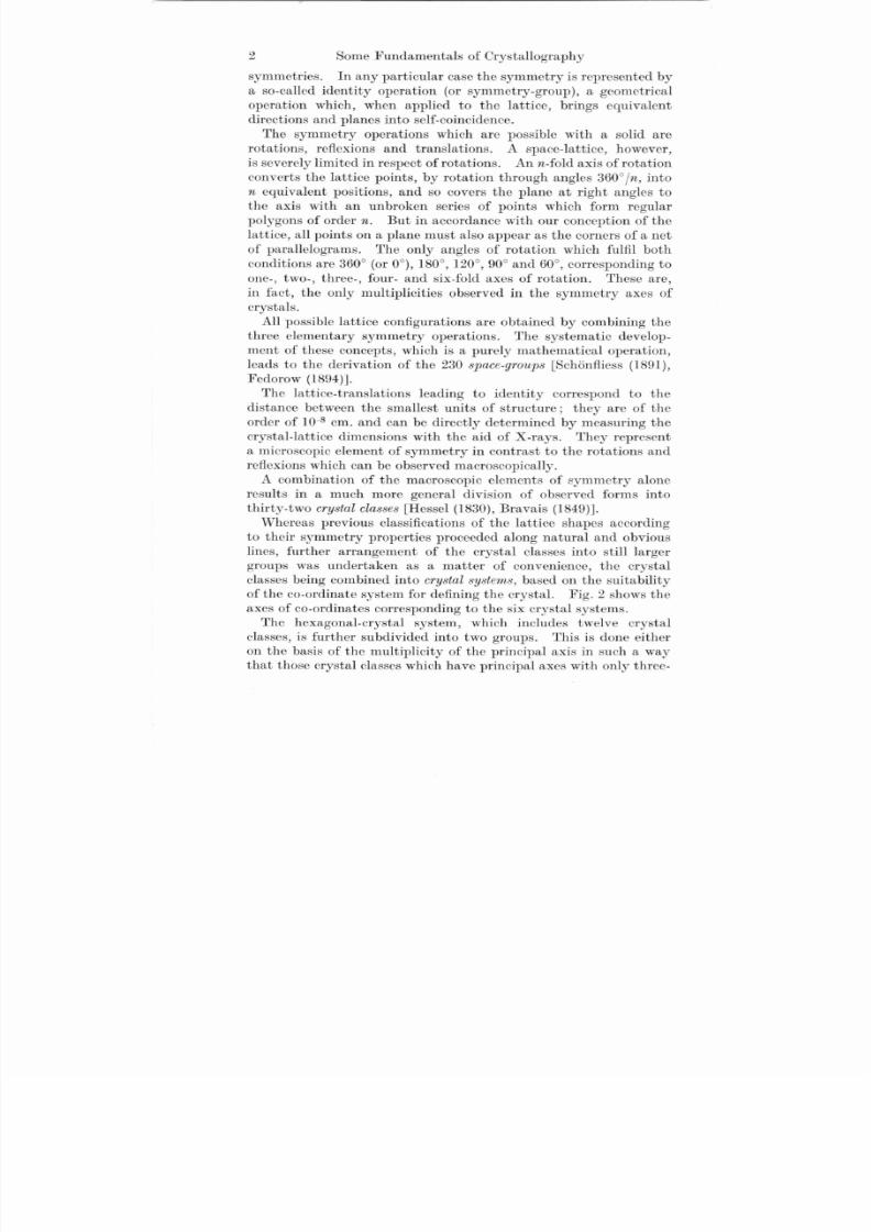
The symmetry operations which are possible with a solid are
rotations, reflexions and translations. A space-lattice, however,
is severely limited in respect of rotations. An n-fold axis of rotation
converts the lattice points, by rotation through angles 360°In , into
n equivalent positions, and so covers the plane at right angles tothe axis with an unbroken series of points which form regular
polygons of order n. But in accordance with our conception of the
lattice, all points on a plane must also appear as the corners of a net
of parallelograms. The only angles of rotation which fulfil both
conditions are 360° (or 0°), 180°, 120°, 90° and 60°, corresponding to
one-, two-, three-, four- and six-fold axes of rotation. These are,
in fact, the only multiplicities observed in the symmetry axes of
crystals.
All possible lattice configurations are obtained by combining the
three elementary symmetry operations. The systematic develop.
ment of these concepts, which is a purely mathematical operation,
leads to the derivation of the 230 space·groups (Sch6nfliess (1891),
Fedorow (1894)J.The lattice-translations leading to identity correspond to the
distance between the smallest units of structure; they are of the
order of 10-8 cm. and can be directly determined by measuring the
crystal.lattice dimensions with the aid of X-rays. They represent
a microscopic element of symmetry in contrast to the rotations and
reflexions which can be observed macroscopically.
A combination of the macroscopic elements of symmetry alone
results in a much more general division of observed forms into
thirty-two crystal classes (Hessel (1830), Bravais (1849)J.
Whereas previous classifications of the lattice shapes according
to their symmetry properties proceeded along natural and obvious
lines, further arrangement of the crystal classes into still larger
groups was undertaken as a matter of convenience, the crystalclasses being combined into crystal systems, based on the suitability
of the co-ordinate system for defining the crystal. Fig. 2 shows the
axes of co-ordinates corresponding to the six crystal systems.
The hexagonal-crystal system, which includes twelve crystal
classes, is further subdivided into two groups. This is done either
on the basis of the multiplicity of the principal axis in such a way
that those crystal classes which have principal axes with only three-
8/9/2019 Schmid Boas 1
http://slidepdf.com/reader/full/schmid-boas-1 17/28
3. Crystal Symmetry 3
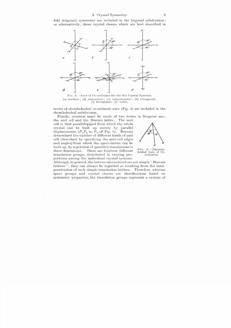
fold (trigonal) symmetry are included in the trigonal subdivision;
or alternatively, those crystal classes which are best described in
-(;'
+1 :
c
'I: +1 :
-a -a
-0
-J
~a ~a
it b-c -c
+1 : +1 :
- - -. • . .~ ;, ;. • •. - - - 4 " -0;-
d e f -(;' -c
FIG. 2.-Axes of Co-ordinates for the Six Crystal Systems.
(a) triclinic; (b ) monoclinic; (c) orthorhombic; (d ) tetragonal;
(e ) hexagonal; (1) cubic.
FIG. 3.-Rhombo-
hedral Axis of Co-ordinates.
aa
(J '
terms of rhombohedral co-ordinate axes (Fig. 3) are included in the
rhombohedral subdivision.
Finally, mention must be made of two terms in frequent use;
the unit cell and the Bravais lattice. The unit
cell is that parallelopiped from which the whole
crystal can be built up merely by parallel
displacements (P1P2 to Ps of Fig. 1). Bravais
determined the number of different kinds of unit
cell (described by specifying the unit-cell edges
and angles) from which the space-lattice can be
built up, by repetition of (parallel) translations in
three dimensions. There are fourteen differenttranslation groups, distributed in varying pro-
portions among the individual crystal systems.
Although, in general, the lattices encountered are not simple "Bravais
lattices", they can always be regarded as resulting from the inter-
penetration of such simple translation lattices. Therefore, whereas
space groups and crystal classes are classifications based on
symmetry properties, the translation groups represent a system of
8/9/2019 Schmid Boas 1
http://slidepdf.com/reader/full/schmid-boas-1 18/28
4 Some Fundamentals of Crystallography
three-dimensional translations leading to the space-lattices; they
afford no indication of the arrangement of the lattice units within
the cell.
4. The Crystallographic Representation of Planes and Directions
The symmetry relationships of crystals have been described, and
in discussing the crystal systems reference has been made to the
systems of co-ordinate axes which can be conveniently used when
defining crystals. We will now consider the method by which planesand directions (lattice planes and axes) can be described crystallo-
graphically.
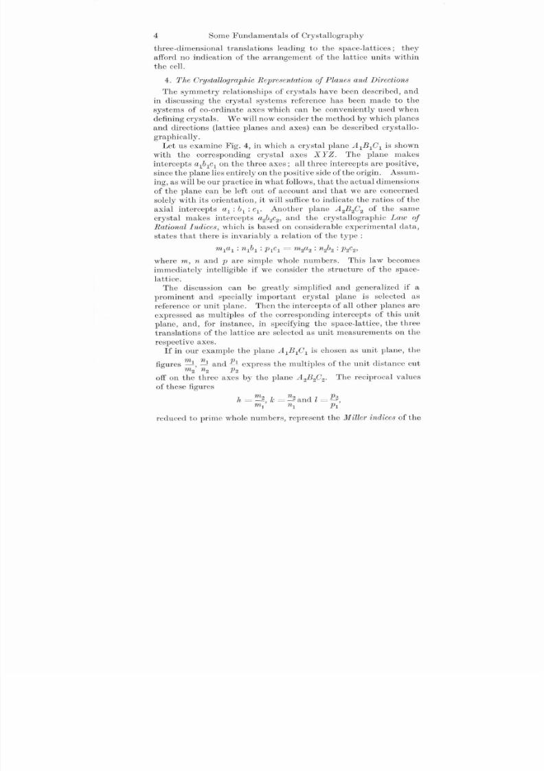
Let us examine Fig. 4, in which a crystal plane AlBlC l is shown
with the corresponding crystal axes XYZ. The plane makes
intercepts alblcl on the three axes; all three intercepts are positive,
since the plane lies entirely on the positive side ofthe origin. Assum-
ing, as will be our practice in what follows,that the actual dimensions
of the plane can be left out of account and that we are concerned
solely with its orientation, it will sufficeto indicate the ratios of the
axial intercepts al: b1 : Cl' Another plane A2 B2C 2 of the same
crystal makes intercepts a2b2c2 , and the crystallographic Law of
Rational Indices, which is based on considerable experimental data,
states that there is invariably a relation of the type:mlal : nlbl :PlC l =m2a2 : n2b2 : P2C 2'
where m, nand P are simple whole numbers. This law becomes
immediately intelligible if we consider the structure of the space-
lattice.The discussion can be greatly simplified and generalized if a
prominent and specially important crystal plane is selected as
reference or unit plane. Then the intercepts of all other planes are
expressed as multiples of the corresponding intercepts of this unit
plane, and, for instance, in specifying the space-lattice, the three
translations of the lattice are selected as unit measurements on the
respective axes.
If in our example the plane A1BlC l is chosen as unit plane, the
figures m[, nl and El express the multiples of the unit distance cutm2 n2 P2
off on the three axes by the plane A2 B2C 2. The reciprocal values
of these figures
h - m2 k = ~ and l = ~- m
J' nJ PI'
reduced to prime whole numbers, represent the Miller indices of the
8/9/2019 Schmid Boas 1
http://slidepdf.com/reader/full/schmid-boas-1 19/28
4. The Grystallographic Representation of Planes and Directions 5
plane A2 B2C 2 or of other planes parallel to it.! The symbol ofthese
crystallographically equivalent planes is written (hkl). The unit
plane, and the array of planes parallel to it, is designated (Ill). A
plane with a zero index, therefore, is parallel to the corresponding
axis (intercepts it at infinity). Planes of co-ordinates passing
through two axes are designated by two zero indices. When a
plane makes equal intercepts along each of the three axes, the
Miller indices are proportional to the direction-cosines of the plane
normal.
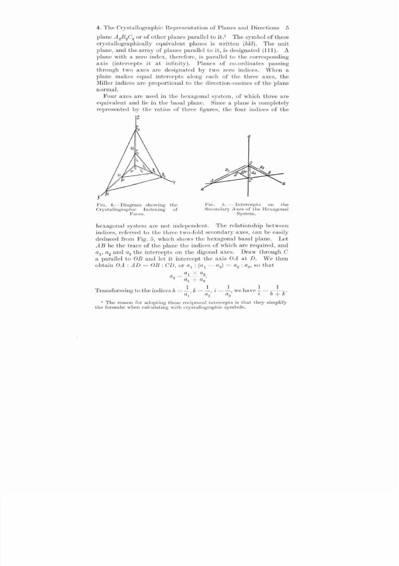
Four axes are used in the hexagonal system, of which three are
equivalent and lie in the basal plane. Since a plane is completely
represented by the ratios of three figures, the four indices of the
Z
l"w. 4.-Diagram showing theCrystallographic Indexing of
Faces.
a
a
a
li'lG. 5. - Intercepts on theSecondary Axes of the Hexagonal
System.
hexagonal system are not independent. The relationship between
indices, referred to the three two-fold secondary axes, can be easily
deduced from Fig. 5, which shows the hexagonal basal plane. Let
AB be the trace of the plane the indices of which are required, and
aI' a2 and a3 the intercepts on the digonal axes. Draw through C
a parallel to OB and let it intercept the axis OA at D. We then
obtain OA : AD = OB: CD, or al :(al - a3) = a2 : a3, so that
al X a2a3=---
al+a2
T r· h· d· Z 1 k 1. 1 h 1 1ranslormlng to t e In Ices L =-, =-, L =-, we ave""7= h + k·al
a2 a3 ~
1 The reason for adopting these reciprocal intercepts is that they simplifythe formulre when calculating with crystallographic symbols.

8/9/2019 Schmid Boas 1
http://slidepdf.com/reader/full/schmid-boas-1 20/28
6 Some Fundamentals of Crystallography
Since the intercept on the a3 axis is negative, we obtain finally
i=(h + k),t i.e., the index applicable to the third axis is always
equal to the negative sum of the first two.2
The crystallographic notation for directions is also based on the
ratios of three figures. The line representing the direction passes
through the origin of co-ordinates, and the co-ordinates are then
determined for a given point lying on the line. These values are
reduced to prime whole numbers, u, v and w, which are distinguished
from the indices of a plane by being placed in square brackets
[uvw]' One zero index indicates that the direction is parallel to one
of the co-ordinate planes. The co-ordinate axes are expressed by
the indices [100], [010] and [001].3
The method of indexing planes and directions can now be described
anew with the aid of the cubic crystal shown in Fig. 6 and the
four-axial hexagonal crystal shown in Fig. 7. The cube faces in Fig. 6,
which are parallel to the axial planes, have indices (100), (010) and
(001). Of the four octahedral planes BDE has the indices (111),
while BDG making an intercept -1 on the Z axis has indices (111).
1The minus sign is always written above the corresponding index.• In addition, the following relations hold between the hexagonal indices
(hkiJ) and the rhombohedral indices (pqr) with first-order pyramidal plane(1011) as rhombohedral plane:
p =2h + k + l; q =k - h + l; r =- 2k - h + l;
h =P - q; k =q - r; i=(h + k); l =P + q +.-!.333
3 In order to specify directions in the four-axial hexagonal system of co-ordinates, assume the direction Z through the origin and a given point Pto be divided into four vector components:
Z =ual + va. + ta3 + wc.
This expression must naturally be identical with one which uses only threeaxes, for instance all a., c.
Z =mal + na2 + wc.
For the secondary axes selected it will be true to say that the sum of their unit vectors, which form an equilateral triangle, disappears:
al + a2 + a3 =O.
If therefore in the above expression for Z, a3 is replaced by - (al + a.), then
by comparing the coefficients we obtain:u - t = 1n; v - t =n,
u, v and t are still not clearly defined by these two equations (a vector can beresolved into three co-planar components in an infinite number of ways).The equation u + v + t =0 is added as an arbitrary condition in the sameway as when specifying the planes. It is now obvious that
2m - n m - 2n m + nu =--3-; v =- --3- ; t =- -3-'
At this stage, however, the indices no longer have any obvious geometricalsignificance.

8/9/2019 Schmid Boas 1
http://slidepdf.com/reader/full/schmid-boas-1 21/28
4. The Crystallographic Representation of Planes and Directions 7
The two remaining octahedral planes are indicated by (Ill) and
(Ill). Of the six dodecahedral planes the plane BDHF is specified
by (1l0), and the plane ACGE, which may be assumed to pass in a
parallel direction through the point B or D, is marked (lIO) or
(110). The two sets of indices become identical on applying the
reduction factor (-1), which, as mentioned above, is always
permissible.
Of the simple directions, reference should be made to AB =[100]
as one of the three edges of the cube, AG = [111] as one of the four
body diagonals, and AF =[lOl] as one of the six face diagonals.
c
z
y
at
FIG. 6.-Method of Indexing the Faces FIG. 7.-Method of Indexing the Facesand Directions of a Cuhic Crystal. and Directions of a Hexagonal Crystal.
The indices of the other crystallographically identical directions
are obtained by transposing the indices (in cyclic order) and by
using the negative sign. Other crystallographically important
directions are those with indices [112]: these twelve identical
directions connect a corner of the cube with a face centre on the
opposite side.
The indices of some of the important planes of hexagonal crystalscan now be easily stated (Fig. 7). The basal plane ABCDEF is
described by the symbol (0001); while the three prism planes
type I (BCJH, CDKJ, ABHG) parallel to the digonal axes are
indicated by (1010), (0110) and (lIOO). The prism planes type II
perpendicular to the digonal axes are indicated by (1120) for
BDKH, etc. The pyramidal planes type I which pass through the
edges of the basal hexagon are indicated by (lOll), where l denotes

8/9/2019 Schmid Boas 1
http://slidepdf.com/reader/full/schmid-boas-1 22/28
FIG. S.-Spherical Projection of aCubic Crystal.
o 0 6: points at which the four-,three- and two-fold axes intersect
the surface.
8 Some Fundamentals of Crystallography
the ordcr of the pyramid (BCP pyramid type I, order 1; BCQ
pyramid type I, order 2). Pyramidal planes of type II correspond
to the indices (112l). (BDP pyramid type II, order 1; BDQ
pyramid type II, order 2.) Among the directions to be noted are
the hexagonal axis with the symbol [0001], the digonal axes type l-
OB, OD and OF-with indices [2110], [1210] and [1120], and finally
one of the digonal axes type II, ON, with the indices [1010].
5. Crystal Projection
Visual representation of the relationships bctween the angles of
crystals, and simple methods for the performance of crystallographic
calculations, areprovided by means
of projections. There are two
principal methods of projection,
spherical and stereographic, both of
whichwill now be briefly described.
In spherical projection a point
on the crystal is assumed to be at
the centre of an imaginary sphere.
The crystal is then set up in such
a way that a principal crystal
axis emerges at the North and South poles. The projection of a
direction is the point at which the
line which has been drawn parallel
to that direction and through
the centre of the sphere meets the
surface. The angle between two
directions is therefore given by the angular distance between the
representative points on the reference sphere. Planes, too, are
represented by a point on the reference sphere, known as the" pole"
of the plane, which is the point at which a plane normal drawn from
the centre of the sphere intersects the surface. The angle between
two planes is given by the distance between the two poles. The
sum of all planes passing through one direction (a zone) is shown onthe polar sphere by a great circle perpendicular to the common
direction or zone axis. By representing the principal planes and
directions in this way the symmetry of the crystals is impressed on
the projection sphere (Fig. 8).
Crystallographic problems are solved by connecting the pro-
jection points (ofplanes and directions) on the polar sphere by great
circles, the required angles being then calculated from convenient
8/9/2019 Schmid Boas 1
http://slidepdf.com/reader/full/schmid-boas-1 23/28
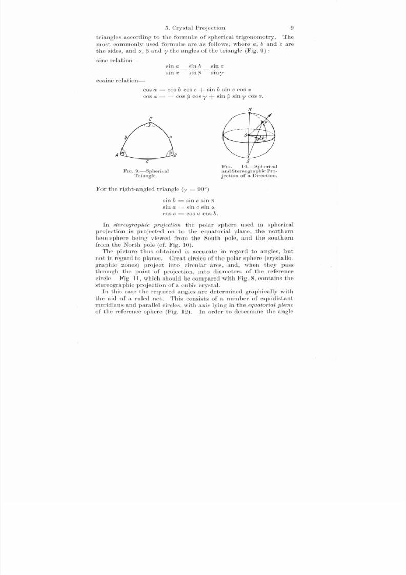
5. Crystal Projection 9
triangles according to the formulm of spherical trigonometry. The
most commonly used formulm are as follows, where a, band care
the sides, and C I ., ~ and y the angles of the triangle (Fig. 9) :
sine relation-sin a sin b sm c
sin C l . - sin ~ - silly
cosine relation-
cos a =cos b cos c + sin b sin c cos Cl.
cos Cl. =- cos ~ cosy + sin ~ sin y cos a.
N
c
FIG. 9.-Spherical
Triangle.
For the right-angled triangle (y =90°)
sin b =sin c sin ~
sin a = sin c sin Cl.
cos c = cos a cos b.
S
FIG. IO.-Sphericaland Stereo graphic Pro-
jection of a Direction.
In stereographic projection the polar sphere used in spherical
projection is projected on to the equatorial plane, the northern
hemisphere being viewed from the South pole, and the southern
from the North pole (cf. Fig. 10).
The picture thus obtained is accurate in regard to angles, but
not in rcgard to planes. Great circles of the polar sphere (crystallo-
graphic zones) project into circular arcs, and, when they passthrough the point of projection, into diameters of the reference
circle. Fig. 11, which should be compared with Fig. 8, contains the
stereographic projection of a cubic crystal.
In this case the required angles are determined graphically with
the aid of a ruled net. This consists of anum ber of equidistant
meridians and parallel circles, with axis lying in the equatorial plane
of the reference sphere (Fig. 12). In order to determine the angle
8/9/2019 Schmid Boas 1
http://slidepdf.com/reader/full/schmid-boas-1 24/28
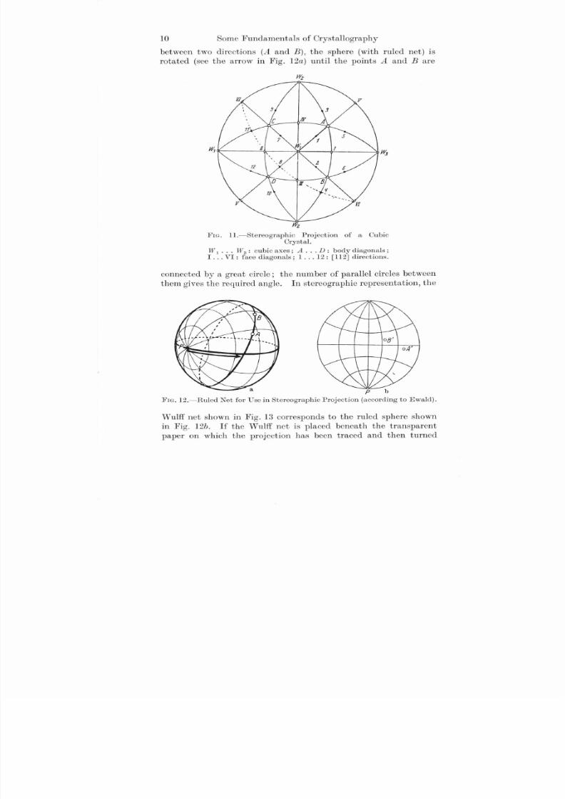
10 Some Fundamentals of Crystallography
between two directions (A and B), the sphere (with ruled net) is
rotated (see the arrow in Fig. 12a) until the points A and Bare
Z
FIG. 11.-Stereographic Projection of a CubicCrystal.
W 1•.• W 3: cubic axes; A D: body diagonals;I ... VI: face diagonals; 1 12: [112] directions.
connected by a great circle; the number of parallel circles between
them gives the required angle. In stereographic representation, the
P b
leIG. 12.-Ruled Net for Use in Stereographic Projection (according to Ewald).
Wulff net shown in Fig. 13 corresponds to the ruled sphere shown
in Fig. 12b. If the Wulff net is placed beneath the transparent
paper on which the projection has been traced and then turned

8/9/2019 Schmid Boas 1
http://slidepdf.com/reader/full/schmid-boas-1 25/28
6. Simple Crystallographic Theorems 11
about its centre, this will correspond to rotation of the ruled sphere.
Angles can be measured in this way to within about i O , the accuracy
attained depending on the distance between the circles on the net.
6. Simple Crystallographic Theorems
The use of crystallographic indices in calculations is illustrated
below, by examples in common use.
FIG. 13.-Wulff's Net.
(a) The direction [uvw] lies in the plane (hkl); the plane (hkl)
belongs to the zone [uvw]'
It follows from the analytical representation of planes and
directions that the relation 1which must be satisfied for coincidence
is hu + kv + lw =O .
Thus, for example, the plane (Il2) belongs to the zone with axis
in the direction [Ill] and not to that with direction [100].
(b) The intersection [uvw] of two planes (hI kIll) and (h2k2l2).
1For the four-figure indices of the hexagonal axis the analogous relation is
hu + kv + it + lw =O.
8/9/2019 Schmid Boas 1
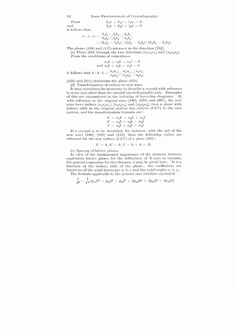
http://slidepdf.com/reader/full/schmid-boas-1 26/28
Some Fundamentals of Crystallography
h1u + le 1v + llW =0
h2u + le 2v + l2 W =0
12
From
and
it follows that
. . _ I leIlI I · III hI 1 · 1 hI lelIU.V.W - lel . lh . hle I
22 22 22
= (le 1l2 - llle 2) : (llh2 - h1l2) : ( h1le 2 - le 1h2)·
The planes (310) and (111) intersect in the direction [132].
(c ) Plane (hlel) through the two directions [U 1V 1W 1] and [u 2v2w2].
From the conditions of coincidence
[123] and [311] determine the plane (185).
(d ) Transformation of indices to new axes.
It may sometimes be necessary to describe a crystal with reference
to some axis other than the natural crystallographic axis. Examples
of this are encountered in the indexing of layer-line diagrams. If,
with reference to the original axes [100], [010] and [001], the new
axes have indices [U 1V 1W 1] , [ u2v2w2] and [U 3V 3W 3], then a plane with
indices (hlel) in the original system has indices (h'le'l') in the new
system, and the transformation formuJ::eare:
h' =u1h + vIle + w1l
le ' =u2h + v2le + w2l
l' =~l3h + v3le + w3l.
If a crystal is to be described, for instance, with the aid of the
new axes [lOO], [010] and [112], then the following values are
obtained for the new indices (h'le'l') of a plane (hlel ) :
h' = h , l e' = le , l ' = h + le + 2l .
(e ) Spacing of lattice planes.
In view of the fundamental importance of the distance betweenequivalent lattice planes for the diffraction of X-rays in crystals,
the general expression for this distance d may be given here. It is a
function of the indices (hlel) of the plane: the coefficients are
functions of the axial intercepts a, b, c and the axial angles ex, ~, y.
The formula applicable to the general case (triclinic crystal) is
~ = t2 {! ll1h2 + !l22le 2 + !l33l2 + 2!l12hl e + 2!l23lcl + 2!l13hl }

8/9/2019 Schmid Boas 1
http://slidepdf.com/reader/full/schmid-boas-1 27/28
Cubic
Tetragonal
6. Simple Crystallographic Theorems 13
where Yn = b2 c2 sin2 a Y 1 2 = ab c2 (c os a . cos ~ - cos y )
Y 2 2 =a2 c2 sin2~ Y 2 3 =a2 bc( cos ~ . cos y - cos a )
Y 3 3 =a2 b2 sin2y Y 1 3 =ab2 c(cos y. cos a - cos~)
V 2 = a2 b2 c2 (1 - cos2a - CO S2 ~ - cos2y + 2 cos a cos ~ cos y)
V represents the volume of the elementary parallelopiped.
Special cases of higher symmetry:
1 ( h )2 (ki2
( l )2Orthorhombic (i2 = a + b) + c.~ _ h
2 + k2
. 7 ! . .
d 2 - a2 + c2
1 h 2 + k2 + l2(l2 = a2
1 4 h 2 + k 2 + h k l2Hexagonal - - - ------ + - (valid for four-number
d2 - 3' a2 c2
indices with i=h + k).
It may be said in general that the simpler the indices of a plane
the greater is the interplanar spacing, and consequently the greater
the number of lattice points per unit area of the plane (density of
distribution). Thus, for example, for the cube face (100) of a cubic
crystal, d =a, for the dodecahedral face (llO),
d =av2,2
while for the octahedral face (Ill),
d =av3.3

8/9/2019 Schmid Boas 1
http://slidepdf.com/reader/full/schmid-boas-1 28/28
CHAPTER I I
ELASTICITY OF CRYSTALS
7. Hooke's Law
If a solid body is subjected to mechanical stresses, elastic deforma-
tions will both precede and accompany plastic strain, i.e., there will
be changes in shape which disappear when the state of stress ceases.In this reversible process the deforrP.ation (which in any ca~e is
usually only very small) is determined solely by the prevailing
stress, from which it can be calculated. The relationship between
stress and strain is linear. This linear characteristic (Hooke's law),
which is based on a wide experience, can now be deduced theoretically
from Born's lattice theory, by assuming that the atoms in the
crystal lattice are in positions of stable equilibrium relative to the
lattice forces. The assumption is justified in so far as it has hitherto
proved impossible to destroy, or even deform to any perceptible
extent, a crystal by the application of infinitesimally small forces.
It is assumed that the forces acting between the particles of the
lattice are central forces; no assumptions are necessary regarding
the law of inter-atomic forces itself when studying elastic behaviour.The distortion of a lattice has two components: the lattice is
deformed as a whole; and, in addition, the simple lattices of which
a crystal is generally composed can, as a whole, be displaced with
reference to each other. This latter type of macroscopically invisible
distortion is a peculiarity of the lattice structure of crystals.
The effect of external forces on a lattice is to displace the lattice
points from equilibrium until the opposing forces set up by distortion
re-establish equilibrium with the external forces. In order to
calculate this behaviour we develop the energy density, whose
derivatives with respect to the strain components are the stresses,
in a power series of the strain components. The linear terms dis-
appear owing to the assumption of the stability of the initial posi-
tion : the components of a third and higher order are neglected. Inthis way the six equations of Hooke's generalized law are obtained:
o"x = cll"x + C12"y + C13"z + cu'Yyz + CI5'Yz:c + C I6 'YXlJ 10"1' = C12"x + C22"y + C 23"z + C 24'Yyz + C 25'Yzx + C 26 'Yxy
0". = C13"x + C23"y + C33". + C34'YYZ + C35'Yz.c + C36'Yxy J'ry• =CI4 "x + C24 "I' + C 34"z + C 44'Yyz + C 45'Yz,c +.C 46 'Yxy (7/1)
'r. x =C15"x + c2. , " y + C35"z + C45'YY' + C 55'Yzx + C 56 'Yxy
"yx = c16"x + C26"y + C36". + C46'Yyz + c56 'Yu - + - C 66 'Yxy
14