schefferville area iron ore mine
TRANSCRIPT

Schefferville Area Iron Ore Mine Western Labrador
ENVIRONMENTAL IMPACT STATEMENTDecember 2008

REPORT TO Labrador Iron Mines Limited 220 Bay Street Suite 700 Toronto ON M5J 2W4
FOR Schefferville Area Iron Ore Mine (Western Labrador)
ON Environmental Impact Statement
December 19 2008
REPORT NO. 1045934

REPORT 1045934 December 19, 2008 i
EXECUTIVE SUMMARY
Introduction
This Environmental Impact Study (EIS) has been prepared for the proposed Schefferville Area Iron Ore Mine (Western Labrador) (the Project) in accordance with the Newfoundland and Labrador Environment Protection Act, Environmental Assessment Regulations and the final EIS Guidelines issued on December 9, 2008. This EIS presents information about the Project and the results of its environmental assessment.
The Project to be developed by Labrador Iron Mines Limited (LIM) will involve the reactivation of two iron ore deposits located in Labrador near Schefferville, Quebec. Open pit mines will be developed at James North, James South, Redmond 2B and Redmond 5 deposits. Although the mine operations will involve the extraction of iron ore, the Project will be smaller than the previous IOC operation (1954 to 1982) and will operate under current regulations, environmental protection standards, and industry best practices.
The EIS identifies and addresses the potential environmental effects on communities, economy and business, caribou, and fish and fish habitat. The assessment process also considers Project feasibility, the Project’s water budget, and potential effects to air quality.
The EIS has been prepared in accordance with Guidelines issued by the Minister of Environment and Conservation (December 9, 2008) to fulfill provincial environmental assessment requirements and will be used by the Minister of Environment and Conservation, in consultation with Cabinet, to determine whether the Project’s environmental effects are acceptable and the Project is to proceed.
Highlights of the Project include:
• the mining of ‘direct shipping’ iron ore deposits in western Labrador in an area of previous iron ore mining;
• mining will be carried out using conventional open pit mining methods, employing drilling and blasting operations;
• additional small excavations that may be required will include borrow pits, quarries and side-hill cuts associated with the construction and maintenance of access roads, mine haulage roads, sumps and settling ponds, and railway spur line construction;
• ore will be beneficiated by crushing, washing and screening at the Silver Yard in Labrador. No chemicals will be used in the beneficiation;
• the beneficiation building will house a primary crusher, tumbling scrubber, secondary crusher, primary screening equipment, secondary screening equipment, filtration equipment, 20T crane and various chutes, conveyors, and pumps;
• the Project is planned to operate an average 212 days/year;
• the beneficiation building and contents will be semi-mobile and modular to fit with the Project’s long-term plans;
• other buildings at the Silver Yard include: mine dry, site offices, laboratory, maintenance shed, and warehouse facilities;

REPORT 1045934 December 19, 2008 ii
• subsequent to washing and screening, the reject fines will be deposited in Ruth Pit, which will become a settling pond to remove suspended solids;
• a 3.5 km rail spur line previously operated and abandoned will be restored, and a siding track will be laid at the Silver Yard;
• water management will include: sourcing beneficiation water from pit water and groundwater; depositing resulting washwater in Ruth Pit; diverting clean drainage away from active mine areas; and maintaining flow to fish habitat using clean groundwater
• standard and proven environmental protection procedures will be employed throughout construction, operation, and rehabilitation and closure;
• an environmental management plan regarding the potential disturbance to avifauna nest sites during construction will be submitted to Environment Canada;
• a Development Plan and Rehabilitation and Closure Plan will be submitted to Mines Branch prior to Project initiation;
• the use of a commute work system for most Project workers;
• a Benefits Policy and associated strategy;
• an Impact and Benefits Agreement with the Innu of Labrador has been signed;
• a Women’s Employment Plan is being developed;
• operation Plans will be prepared and submitted annually; and,
• the site specific Environmental Protection Plan (EPP) will be submitted to the Minister of Environment and Conservation for approval before any construction on the project begins.
Local and Regional benefits include:
• approximately 100 direct jobs during construction and 65 during operation;
• 5 years duration of employment;
• between $30 million and $60 million per year in total operating costs, much of which will be accrued to the Province of Newfoundland and Labrador;
• close working with the Innu of Labrador involving them in provision of labour, goods, and services;
• maximum use of qualified mining contractors and other services based elsewhere in the region, such as Labrador City, Wabush and Happy Valley-Goose Bay; and
• LIM is committed to the creation and implementation of employment equity practices to promote recruitment, training, and advancement of qualified visible minorities and women.
Issues Scoping
LIM conducted an extensive issues scoping process in relation to the Project, which included consultation with appropriate regulatory agencies, the public, and Aboriginal groups, in order to identify the potential environmental issues associated with it. The EIS includes consideration of the environmental effects of the proposed Project, including the potential effects of each of its components/phases and any of these predicted environmental effects is also evaluated. Mitigation measures which are technically and economically feasible have been incorporated into Project design and planning and additional VEC-specific mitigation has also been identified and proposed as required and appropriate.

REPORT 1045934 December 19, 2008 iii
Valued Environmental Components
Valued Environmental Components identified in the Guidelines and discussed in the EIS include Employment and Business, Communities, Fish and Fish Habitat, and Caribou.
Fish and Fish Habitat
The potential effects to fish and fish habitat have been considered and, with diligent application of mitigative and environmental protection measures, the residual and cumulative environmental effects are expected to be not significant under definitions for environmental assessment. LIM will adhere to the following mitigation measures to reduce or eliminate adverse effects on fish and fish habitat:
• vegetated buffer zones;
• sediment and erosion control measures;
• proper wastewater management measures;
• proper solid and liquid waste management measures;
• no blasting near water; and
• a no-fishing policy will be implemented to protect local fisheries resources from potential depletion.
Follow-up and monitoring measures that will be applied to ensure compliance with provincial and federal regulations and to verify the impact predictions include:
• water quality monitoring under provincial and federal approvals and regulations;
• Environmental Effects Monitoring (EEM) under provincial and federal approvals and regulations.
Caribou
The Project may affect migratory caribou from the George River Herd which occasionally occupy this area, through changes in habitat availability or effectiveness, changes in movement patterns, and increased mortality through influences affecting predation/poaching/hunting and vehicle collisions.
In order to mitigate potential effects of the Project on caribou, activities during all phases of the Project will be planned with two main considerations:
• in the event that caribou are observed within the Assessment Area or in the vicinity of Project activities, a set of procedures will be incorporated to avoid encounters with caribou; and
• any activity that may potentially affect caribou habitat or mortality in some manner regardless of whether caribou are actually present.
Specific mitigation measures will include:
• no hunting;
• vehicles will yield to, and not harass wildlife;
• in the event blasting was scheduled, this activity would be delayed until caribou are at least 3 km distant.
Residual and cumulative environmental effects on caribou are determined to be “not significant”. Applying mitigation measures, as listed above, will reduce adverse environmental effects. Monitoring and follow-up will consist of an assessment of potential use of the area through a series of aerial

REPORT 1045934 December 19, 2008 iv
surveys. The surveys will be conducted to gain information on distribution and local habitat use (if they are present) during seasonal periods. They will be completed during the calving, fall rut and winter season to obtain a complete year perspective.
Employment and Business
Employment and Business was chosen as a VEC based on public concern that economic benefits accrue to local communities, Labrador and the Province as a whole. This includes benefits to the population and economy as a whole, and to under-represented groups.
It has been determined that the Project will make a contribution to the further economic development of the Province and, in particular, Labrador, by:
• providing local employment and incomes during construction and operation;
• providing local business during construction and operation;
• increasing the capacity and skills of local labour force and businesses; and
• facilitating further mining development by putting in place these new labour and business capabilities and new transportation infrastructure, thereby making existing and new Labrador projects more competitive globally.
These net positive effects will be particularly valued given the recent economic downturn in Labrador West.
No significant adverse residual or cumulative effects are expected on Employment and Business.
LIM will monitor Project employment and expenditures, including the proportions of work going to Labrador, the Innu of Labrador, women and the Province as a whole. This information will be compiled on an annual basis and made available to government upon request. Provisions respecting the employment of women will be specified in the Women’s Employment Plan.
Communities
Communities are another aspect of socio-economic environment that may be affected by the Project. The communities most likely to be affected are the primary places of residence of the Project labour force: Labrador West, Upper Lake Melville and Schefferville. The construction, operation, and decommissioning phases of the Project will have negligible adverse short-term direct effects on the communities of Labrador West and Upper Lake Melville.
The monitoring of demands on community services and infrastructure is the responsibility of the relevant government departments and agencies, as part of their normal planning processes. LIM will assist by liaising with them, as requested, and through the timely provision of information about Project activity and plans.
Conclusion
Significant adverse environmental effects are not predicted in relation to the Project’s construction, operation, or decommissioning phases, or as a result of accidental events. The Project is therefore not likely to cause significant adverse environmental effects. A monitoring and follow-up program will be undertaken to assess the accuracy of the effects predictions made in the environmental assessment, and to determine the effectiveness of mitigation measures.

REPORT 1045934 December 19, 2008 v
The Project will result in considerable socio-economic benefits accruing to the Province of Newfoundland and in particular Labrador. It will create considerable direct and indirect employment and business opportunities, and contribute substantially to the economy of the local area of Labrador, as well as that of the Province of Newfoundland and Labrador as a whole.

REPORT 1045934 December 19, 2008 vi
Table of Contents EXECUTIVE SUMMARY ............................................................................................................ i
1.0 INTRODUCTION ........................................................................................................................ 1 1.1 Project Overview ........................................................................................................................ 1 1.2 The Proponent ........................................................................................................................... 2 1.3 Regulatory Framework ............................................................................................................... 3 1.3.1 Provincial Environmental Assessment Process ...................................................................... 3 1.3.2 Environmental Authorizations ................................................................................................. 4 1.4 Environmental Impact Statement Purpose ................................................................................. 4 1.5 Document Organization ............................................................................................................. 4 1.5.1 Other Related Documentation ................................................................................................. 5
2.0 PROPOSED UNDERTAKING ................................................................................................... 6 2.1 The Project ................................................................................................................................. 6 2.1.1 Project Location ...................................................................................................................... 6 2.1.2 Site History .............................................................................................................................. 8 2.1.3 Project Purpose and Rationale ............................................................................................... 8 2.2 Environmental Management and Corporate Responsibility Policies ........................................ 11 2.3 Alternatives .............................................................................................................................. 13 2.4 Regulatory Approval Requirements ......................................................................................... 14
3.0 PROJECT DESCRIPTION ....................................................................................................... 16 3.1 Project Features ....................................................................................................................... 16 3.1.1 Mineral Licenses ................................................................................................................... 16 3.1.3 Mine and Borrow Pits ............................................................................................................ 20 3.1.3.1 James and Redmond Mines .............................................................................................. 20 3.1.3.2 Waste Rock Disposal ......................................................................................................... 20 3.1.3.3 Minor Excavations and Borrow Pits ................................................................................... 21 3.1.4 Mine Infrastructure ................................................................................................................ 25 3.1.5 Supporting Infrastructure ....................................................................................................... 29 3.1.6 Railway Infrastructure ........................................................................................................... 31 3.1.7 Surface Water Management ................................................................................................. 35 3.1.8 Clearance and Condemnation Work ..................................................................................... 36 3.1.9 Waste Management .............................................................................................................. 37 3.1.9.1 Wastewater and Sewage ................................................................................................... 37 3.1.9.2 Domestic and Solid Waste Disposal .................................................................................. 38 3.1.9.3 Hazardous Waste ............................................................................................................... 38 3.1.9.4 Beneficiation Plant Waste Effluent ..................................................................................... 38 3.1.9.5 Waste Rock ........................................................................................................................ 39 3.2 Construction ............................................................................................................................. 39 3.2.1 Project Schedule ................................................................................................................... 39 3.2.2 Site Preparation .................................................................................................................... 40 3.2.3 Construction Infrastructure and Activities .............................................................................. 43 3.2.4 Pit Dewatering ....................................................................................................................... 44 3.2.5 Housing and Transportation .................................................................................................. 45

REPORT 1045934 December 19, 2008 vii
3.2.6 Predicted Construction Emissions and Discharges .............................................................. 45 3.2.7 Site Rehabilitation and Monitoring ........................................................................................ 46 3.2.8 Employment .......................................................................................................................... 46 3.2.9 Goods and Services .............................................................................................................. 47 3.2.10 Newfoundland and Labrador Benefits Strategy .................................................................... 48 3.3 Operation and Maintenance ..................................................................................................... 49 3.3.1 Operation and Maintenance Activities ................................................................................... 49 3.3.1.1 Excavation .......................................................................................................................... 49 3.3.1.2 Haulage .............................................................................................................................. 50 3.3.1.3 Drilling and Blasting ........................................................................................................... 50 3.3.1.4 Processing ......................................................................................................................... 50 3.3.1.5 Product Export ................................................................................................................... 50 3.3.1.6 Rock Fines Disposal .......................................................................................................... 50 3.3.1.7 Maintenance Activities ....................................................................................................... 50 3.3.2 Operation Air Emissions ........................................................................................................ 51 3.3.2.1 Emissions from Beneficiation Facility ................................................................................. 51 3.3.2.2 Fugitive Dust ...................................................................................................................... 51 3.3.2.3 Emissions from Ore Hauling from Mine Site to Beneficiation Area .................................... 52 3.3.2.4 Emissions from Mining ....................................................................................................... 52 3.3.3 Operation Discharges ........................................................................................................... 53 3.3.4 Chemical Storage/Management ............................................................................................ 53 3.3.5 Water Management ............................................................................................................... 53 3.3.5.1 James Deposit ................................................................................................................... 53 3.3.5.2 Redmond Property ............................................................................................................. 53 3.3.5.3 Wash Water ....................................................................................................................... 54 3.3.5.4 Sanitary (Non-Potable) Water System ............................................................................... 54 3.3.5.5 Potable Water .................................................................................................................... 54 3.3.5.6 Dewatering Water .............................................................................................................. 54 3.3.6 Progressive Rehabilitation .................................................................................................... 54 3.3.7 Employment .......................................................................................................................... 55 3.3.8 Goods and Services .............................................................................................................. 56 3.3.9 Newfoundland and Labrador Benefits Strategy .................................................................... 57 3.4 Decommissioning ..................................................................................................................... 57 3.4.1 Closure Rehabilitation ........................................................................................................... 57
4.0 ENVIRONMENTAL SETTING ................................................................................................. 59 4.1 Physical Environment ............................................................................................................... 59 4.1.1 Climate .................................................................................................................................. 59 4.1.2 Air Quality .............................................................................................................................. 60 4.1.2.1 Existing Conditions ............................................................................................................. 60 4.1.2.2 Emissions Inventory ........................................................................................................... 61 4.1.2.3 Air Quality Modeling Methodology ..................................................................................... 61 4.1.3 Air Quality Modelling Results ................................................................................................ 64 4.1.3.1 Potential Changes in Air Quality due to Project Activities .................................................. 65 4.1.4 Landscape ............................................................................................................................. 68 4.1.4.1 Regional Geology ............................................................................................................... 68 4.1.4.2 Knob Lake Range Geology ................................................................................................ 69 4.1.4.3 Regional Mineralization ...................................................................................................... 71

REPORT 1045934 December 19, 2008 viii
4.1.4.4 Deposit Types .................................................................................................................... 72 4.1.4.5 Geomorphology, Surficial Geology, Soils and Permafrost ................................................. 74 4.1.4.6 Acid Rock Drainage ........................................................................................................... 76 4.1.5 Hydrology .............................................................................................................................. 77 4.1.5.1 James Property .................................................................................................................. 77 4.1.5.2 Redmond Property ............................................................................................................. 88 4.1.6 Ambient Water Quality .......................................................................................................... 92 4.1.6.1 Groundwater Quality .......................................................................................................... 92 4.2 Biological Environment ............................................................................................................. 98 4.2.1 Wetlands and Flora ............................................................................................................... 98 4.2.1.1 Description of Study Area .................................................................................................. 98 4.2.1.2 Methods ............................................................................................................................. 99 4.2.1.3 Wetlands .......................................................................................................................... 103 4.2.2 Wildlife ................................................................................................................................. 104 4.2.2.1 Caribou ............................................................................................................................. 104 4.2.2.2 Other species ................................................................................................................... 110 4.2.3 Avifauna .............................................................................................................................. 114 4.2.3.1 Methods ........................................................................................................................... 114 4.2.3.2 Results ............................................................................................................................. 115 4.2.3.3 Raptors ............................................................................................................................. 118 4.2.4 Fish and Fish Habitat .......................................................................................................... 118 4.2.4.1 Methods ........................................................................................................................... 118 4.2.4.2 Assessment Area Boundaries .......................................................................................... 120 4.2.4.3 Results ............................................................................................................................. 121 4.2.4.4 Current and Future Fisheries ........................................................................................... 123 4.3 Socio-economic ...................................................................................................................... 123 4.3.1 Methodology ........................................................................................................................ 125 4.3.2 Demography ........................................................................................................................ 125 4.3.2.1 Population ........................................................................................................................ 125 4.3.3 Employment and Business .................................................................................................. 130 4.3.3.1 Introduction ...................................................................................................................... 130 4.3.3.2 Employment ..................................................................................................................... 131 4.3.3.3 Business ........................................................................................................................... 133 4.3.4 Communities ....................................................................................................................... 136 4.3.4.1 Housing ............................................................................................................................ 136 4.3.4.2 Healthcare ........................................................................................................................ 137 4.3.4.3 Education ......................................................................................................................... 140 4.3.4.4 Recreation ........................................................................................................................ 143 4.3.4.5 Transportation .................................................................................................................. 144 4.3.4.6 Water, Sewer, Solid Waste, Power and Communications ............................................... 146 4.4 Data Availability and Gaps ..................................................................................................... 148 4.5 Future Environment ................................................................................................................ 148
5.0 PUBLIC CONSULTATION AND ISSUE SCOPING .............................................................. 150 5.1 Public Information Sessions ................................................................................................... 150 5.1.1 Session Schedule ............................................................................................................... 150 5.1.2 Public Notifications .............................................................................................................. 150 5.1.3 The Sessions ...................................................................................................................... 151

REPORT 1045934 December 19, 2008 ix
5.1.4 Attendance .......................................................................................................................... 151 5.1.5 Issues and Questions Raised ............................................................................................. 152 5.1.5.1 Happy Valley-Goose Bay ................................................................................................. 152 5.1.5.2 Wabush-Labrador City ..................................................................................................... 152 5.1.5.3 Schefferville ...................................................................................................................... 152 5.1.6 Summary ............................................................................................................................. 153 5.2 Aboriginal Consultations ........................................................................................................ 153 5.3 Other Consultation ................................................................................................................. 153 5.4 Selection of Valued Environmental Components ................................................................... 154
6.0 ENVIRONMENTAL EFFECTS ASSESSMENT ..................................................................... 155 6.1 Fish and Fish Habitat ............................................................................................................. 155 6.1.1 Environmental Assessment Boundaries ............................................................................. 156 6.1.2 Existing Fish and Fish Habitat Environment ....................................................................... 156 6.1.3 Potential Project-Fish and Fish Habitat Interactions ........................................................... 156 6.1.3.1 Construction ..................................................................................................................... 156 6.1.3.2 Operation ......................................................................................................................... 156 6.1.3.3 Decommissioning ............................................................................................................. 157 6.1.4 Environmental Effects Assessment, Management, and Residual Effects Determination ... 159 6.1.4.1 Residual Environmental Effects Significance Criteria ...................................................... 159 6.1.4.2 Summary of Residual Environmental Effects Prediction .................................................. 160 6.1.5 Cumulative Environmental Effects ...................................................................................... 162 6.2 Caribou ................................................................................................................................... 162 6.2.1 Environmental Assessment Boundaries ............................................................................. 163 6.2.2 Potential Project-VEC Interactions ...................................................................................... 163 6.2.2.1 Construction ..................................................................................................................... 163 6.2.2.2 Operation ......................................................................................................................... 164 6.2.2.3 Decommissioning ............................................................................................................. 164 6.2.2.4 Potential Effects and Review of Existing Knowledge ....................................................... 164 6.2.3 Residual Environmental Effects Significance Criteria ......................................................... 166 6.2.4 Mitigation Measures ............................................................................................................ 167 6.2.5 Environmental Effects Assessment, Management, and Residual Effects Determination ... 169 6.2.5.1 Construction ..................................................................................................................... 169 6.2.5.2 Operation ......................................................................................................................... 169 6.2.5.3 Decommissioning ............................................................................................................. 170 6.2.5.4 Summary of Residual Environmental Effects Prediction .................................................. 170 6.2.6 Cumulative Environmental Effects ...................................................................................... 171 6.3 Employment and Business ..................................................................................................... 173 6.3.1 Potential Project-VEC Interactions ...................................................................................... 173 6.3.2 Employment and Business Assessment ............................................................................. 173 6.3.3 Cumulative Environmental Effects ...................................................................................... 179 6.4 Communities .......................................................................................................................... 180 6.4.1 Potential Project-VEC Interactions ...................................................................................... 180 6.4.2 Communities Assessment ................................................................................................... 180 6.4.3 Implications for Other Mining Projects, Railways and Mineral Exploration ......................... 182 6.5 Accidental Events ................................................................................................................... 183 6.5.1 Fish and Fish Habitat .......................................................................................................... 183 6.5.2 Caribou ................................................................................................................................ 183

REPORT 1045934 December 19, 2008 x
6.5.3 Employment and Business .................................................................................................. 184 6.5.4 Communities ....................................................................................................................... 184 6.6 Effects of the Environment on the Project .............................................................................. 184 6.6.1 Climate Change Predictions ................................................................................................ 185 6.6.1.1 Temperature and Precipitation ......................................................................................... 185 6.6.1.2 Water Table and Lake Levels .......................................................................................... 186 6.6.1.3 Wind Speed ...................................................................................................................... 186 6.6.1.4 Extreme Weather ............................................................................................................. 186 6.6.2 Project Sensitivity to Climate Change ................................................................................. 186 6.6.3 Summary of Effects of the Environment on the Project....................................................... 188
7.0 ENVIRONMENTAL PROTECTION ....................................................................................... 189 7.1 Mitigation ................................................................................................................................ 189 7.1.1 Blasting ............................................................................................................................... 189 7.1.2 Reject Fines Wash Water Slurry ......................................................................................... 189 7.1.3 Stormwater Management .................................................................................................... 190 7.1.4 Mine Dewatering ................................................................................................................. 190 7.1.5 Grey Water/Domestic Sewage Management ...................................................................... 190 7.1.6 Air Quality ............................................................................................................................ 190 7.1.6.1 Mitigation .......................................................................................................................... 190 7.2 Emergency Response/Contingency Plans ............................................................................. 191 7.2.1 Hazard Identification and Risk Assessment ........................................................................ 191 7.2.2 Emergency Response Plan ................................................................................................. 192 7.2.3 Mutual Aid Agreement ......................................................................................................... 193 7.2.4 Contingency Plan ................................................................................................................ 193 7.3 Environmental Monitoring and Follow-Up Programs .............................................................. 194 7.3.1 Air Quality ............................................................................................................................ 194 7.3.2 Water Quality and Environmental Effects Monitoring .......................................................... 194 7.3.3 Caribou ................................................................................................................................ 195 7.3.4 Employment and Business .................................................................................................. 195 7.3.5 Communities ....................................................................................................................... 195 7.4 Rehabilitation ......................................................................................................................... 195 7.4.1 Beneficiation Infrastructure ................................................................................................. 196 7.4.2 Salvage ............................................................................................................................... 196 7.4.3 Roads, Pipelines and Power Distribution Lines .................................................................. 196 7.4.4 Stormwater Management Settling Pond and Diversion Ditches.......................................... 196 7.4.5 Overburden and Waste Rock Stockpiles ............................................................................ 196 7.4.6 Open Pits ............................................................................................................................ 197 7.4.7 Fuel and Hazardous Materials Storage Facilities ................................................................ 197 7.4.8 Borrow Pits .......................................................................................................................... 197 7.4.9 Explosives Storage ............................................................................................................. 197 7.4.10 Revegetation ....................................................................................................................... 197 7.4.11 Monitoring ........................................................................................................................... 197 7.5 Environmental Protection Plan ............................................................................................... 198
8.0 SUMMARY AND CONCLUSION ........................................................................................... 201 8.1 Mitigation ................................................................................................................................ 201 8.2 Residual Environmental Effects ............................................................................................. 202

REPORT 1045934 December 19, 2008 xi
8.3 Follow-up and Monitoring ....................................................................................................... 203 8.4 Conclusion ............................................................................................................................. 204
9.0 REFERENCES ....................................................................................................................... 205 9.1 Personal Communications ..................................................................................................... 205 9.2 Literature Cited ....................................................................................................................... 207 9.3 Internet Sites .......................................................................................................................... 213
List of Tables
Table 2.1 Environmental Authorizations that May be Required for the Schefferville Area Iron Ore Mine ............................................................................................................ 14
Table 3.1 James Property Licenses .......................................................................................... 18 Table 3.2 Redmond Property Licenses ..................................................................................... 19 Table 3.3 Estimated Production Schedule ................................................................................ 39 Table 3.4 Construction Phase Employment .............................................................................. 47 Table 3.5 Equipment Types and Numbers ................................................................................ 50 Table 3.6 Operation Phase Employment................................................................................... 55 Table 4.1 Summary of Average Temperature Data................................................................... 59 Table 4.2 Summary of Average Precipitation Data ................................................................... 59 Table 4.3 Summary of Wind Data ............................................................................................. 60 Table 4.4 Acid Base Accounting (ABA) Results ........................................................................ 78 Table 4.5 Measured Stream Velocities...................................................................................... 80 Table 4.6 Measured Flows ........................................................................................................ 81 Table 4.7 Maximum, Minimum and Mean Flows ....................................................................... 81 Table 4.8 Meteorological Data - Daily Averages (1949 - 2007) ................................................. 81 Table 4.9 James Creek/Bean Lake Water Balance Summary .................................................. 86 Table 4.10 Maximum, Minimum and Mean Flows, June to October ........................................... 86 Table 4.11 Maximum and Mean Flows, Unnamed Tributary ....................................................... 87 Table 4.12 Measured Stream Velocities...................................................................................... 90 Table 4.13 Measured Flows ........................................................................................................ 90 Table 4.14 Maximum, Minimum and Mean Flows ....................................................................... 91 Table 4.15 Population Estimates for Five Herds in Southern Labrador .................................... 109 Table 4.16 Population of Labrador West, Upper Lake Melville, Labrador and Province, 2006 . 127 Table 4.17 Labour Force Characteristics, 2006 ........................................................................ 131 Table 4.18 Beneficiaries of Employment Insurance, Labrador City and Wabush, 2002 to
2006 ........................................................................................................................ 131 Table 4.19 Number of Businesses by Employment Size Range, Hyron Regional Economic
Development Corporation, December 2006 ............................................................ 134 Table 4.20 Number of Businesses by North American Industrial Classification System Code,
Hyron Regional Economic Development Corporation, December 2006 ................. 134 Table 4.21 Major Employers and Number of Employees, Upper Lake Melville ........................ 135 Table 4.22 Number of Businesses, Upper Lake Melville, 2006 ................................................. 136 Table 4.23 Schools, Enrolment and Number of Teachers, Labrador City and Wabush,
2007-08 ................................................................................................................... 140 Table 4.24 College of the North Atlantic Enrolment by Program, Labrador City Campus,
2008/2009 ............................................................................................................... 141 Table 4.25 Student Populations, Primary and Secondary Schools, 2006 to 2007 .................... 142

REPORT 1045934 December 19, 2008 xii
Table 4.26 College of the North Atlantic, Enrolment by Program, Happy Valley-Goose Bay Campus, 2005/2006 ................................................................................................ 143
Table 5.1 Public Information Session Schedule ...................................................................... 150 Table 5.2 Public Information Session Attendance ................................................................... 152 Table 6.1 Potential Project-VEC Interactions for Fish and Fish Habitat .................................. 157 Table 6.2 Summary of Residual Environmental Effects for Fish and Fish Habitat:
Construction ............................................................................................................ 160 Table 6.3 Summary of Residual Environmental Effects for Fish and Fish Habitat: Operation 161 Table 6.4 Summary of Residual Environmental Effects for Fish and Fish Habitat:
Decommissioning .................................................................................................... 161 Table 6.5 Summary of Residual Environmental Effects for Fish and Fish Habitat:
Cumulative Effects .................................................................................................. 162 Table 6.6 Potential Project-VEC Interactions for Caribou ....................................................... 164 Table 6.7 Proposed Mitigation Measures for Caribou ............................................................. 167 Table 6.8 Summary of Residual Environmental Effects for Caribou Construction .................. 170 Table 6.9 Summary of Residual Environmental Effects for Caribou Operation ....................... 171 Table 6.10 Summary of Residual Environmental Effects for Caribou: Decommissioning ......... 171 Table 6.11 Projects and Activities Considered in Cumulative Environmental Effects
Assessment ............................................................................................................. 172 Table 6.12 Summary of Residual Environmental Effects for Caribou: Cumulative Effects ....... 173 Table 6.13 Summary of Residual Environmental Effects for Employment and Business (All
Phases) ................................................................................................................... 179 Table 6.14 Summary of Residual Environmental Effects for Communities (All Phases) ........... 182 Table 6.15 Projected Mean Annual Maximum and Minimum Temperature Increases, and
Percent Precipitation Change for the 2020s, 2050s, and 2080s ............................. 185 Table 6.16 Project Sensitivities to Direct and Indirect Climate Influences ................................. 187 Table 7.1 Environmental Protection Plan Table of Contents ................................................... 200 Table 8.1 Mitigative Measures Applicable to Each VEC ......................................................... 202 Table 8.2 Summary of Residual Environmental Effects .......................................................... 203
List of Figures
Figure 2.1 Project Location ........................................................................................................... 7 Figure 3.1 Project Features ........................................................................................................ 17 Figure 3.2 Mineral Licenses, James Property ............................................................................ 18 Figure 3.3 Mineral Licenses, Redmond Property ....................................................................... 19 Figure 3.4 James and Silver Yard Infrastructure ........................................................................ 22 Figure 3.5 Redmond Infrastructure ............................................................................................. 23 Figure 3.6 Existing Pits (Potential Borrow Areas) ....................................................................... 24 Figure 3.7 Overall Beneficiation Process Flow Diagram ............................................................ 26 Figure 3.8 Preliminary Water Balance ........................................................................................ 29 Figure 3.9 Existing Railway Infrastructure .................................................................................. 33 Figure 3.10 Proposed Railway Infrastructure ............................................................................... 34 Figure 3.11 Project Schedule ....................................................................................................... 40 Figure 3.12 Extent of Vegetation Clearing, James ....................................................................... 41 Figure 3.13 Extent of Vegetation Clearing, Redmond .................................................................. 42 Figure 4.1 Sensitive Receptor Locations .................................................................................... 63 Figure 4.2 Maximum Predicted 1-hr NOX Ground-level Concentrations .................................... 66 Figure 4.3 Maximum Predicted 24-hr TSP Ground-level Concentrations ................................... 67

REPORT 1045934 December 19, 2008 xiii
Figure 4.4 Geological Map (Project Area) .................................................................................. 70 Figure 4.5 Generalized Cross Section-James Deposits ............................................................. 74 Figure 4.6 Permafrost Distribution in Nouveau-Quebec and Labrador (Source Brown, 1979) ... 75 Figure 4.7 James Creek/Bean Lake Drainage Area ................................................................... 79 Figure 4.8 SG-4 Stream Gauge Data on June 6 and 18, September 8 and 25 .......................... 82 Figure 4.9 SG-5 Stream Gauge Data on June 6 and 18, September 8 and 25 .......................... 83 Figure 4.10 Monitoring Wells and Stream Gauges Locations ...................................................... 84 Figure 4.11 James Springs and Unnamed Tributary .................................................................... 87 Figure 4.12 Redmond Property Drainage Area ............................................................................ 89 Figure 4.13 Surface Water Sampling Stations, James ................................................................. 93 Figure 4.14 Surface Water Sampling Stations, Redmond ............................................................ 94 Figure 4.15 Caribou Assessment Area ....................................................................................... 105 Figure 4.16 Selected Caribou Herd Ranges, Labrador and Northeast Quebec ......................... 108 Figure 4.17 Bird Monitoring Locations ........................................................................................ 116 Figure 4.18 Lakes and Streams in the Project Area ................................................................... 119 Figure 4.19 Study Area and Economic Zones of Labrador......................................................... 124 Figure 4.20 Population by Economic Zone, as a Percentage of Labrador’s Population, 2006 ... 126 Figure 4.21 Population of Labrador Economic Zones by Age Group, 2006 ............................... 127 Figure 4.22 Labour Force by Industry, Labrador West, 2006 ..................................................... 132 Figure 4.23 Labour Force by Occupation, Labrador West, 2006 ................................................ 132 Figure 4.24 Education Level, Labrador West, 2006 ................................................................... 133 Figure 4.25 Education Level, Upper Lake Melville, 2006 ........................................................... 133 Figure 4.26 Employment by Industry, Upper Lake Melville, 2006 .............................................. 135
List of Appendices Appendix A EIS Guidelines and Table of Concordance
Appendix B EIS Study Team Appendix C List of Documents Appendix D Benefits Policy Appendix E Correspondence from DFO Appendix F New Millennium News Release Appendix G Beneficiation Process Appendix H Ambient Air Quality and Modelling Methods Appendix I Air Quality Modelling Results Appendix J Water Quality Appendix K Hydrological Field Study Methods Appendix L Vegetation Species List and Photographs Appendix M Bird Species Appendix N Fish Habitat Assessment Report, James Property Unnamed Tributary Appendix O Summary of Stakeholder Consultation Appendix P Public Information Sessions Notice Appendix Q Project Summary Handout Appendix R Public information Session Presentation Appendix S Environmental Assessment Methods

REPORT 1045934 December 19, 2008 1
1.0 INTRODUCTION
1.1 Project Overview
The Schefferville Area Iron Ore Mine (Western Labrador) (the Project) is being developed by Labrador Iron Mines Limited (“LIM”) which is a wholly owned subsidiary of Labrador Iron Mines Holdings Limited, a public company listed on the Toronto Stock Exchange.
LIM has identified eight separate ore grade deposits located across a 100km strike length all in Labrador. The four central deposits are located within 10 kilometres of the location of Silver Yard, Labrador, which is some three kilometres west of Schefferville Quebec.
The Project involves development and mining of ‘direct shipping’ iron ore deposits in the northwest of western Labrador in an area of previous iron ore mining. High grade hematite iron ore will be mined from a number of identified deposits on sites where similar mining has taken place in the past. Mining will be carried out in a sequential manner using conventional open pit mining methods. When mined, the rock will be beneficiated at a single location in Labrador. The resultant products will include lump ore and sinter fines for direct rail transport to port and shipping to end users in Europe and possibly Asia.
The size of the operation proposed for this Project is small by world-wide iron ore standards and small compared to other iron ore projects carried out elsewhere in the Province and previously in this area. The Project is based on previously developed brownfield sites and this and the small size will ensure that the adverse social and environmental impacts of the Project will be both limited in range and in time.
The Project benefits from and relies upon the significant level of pre-existing infrastructure that was put in place for previous mining operations that were subsequently closed during the 1980’s. The existence of these infrastructure facilities, the majority of which are still in sound operational condition, will ensure that new build facilities will be kept to a minimum with the ensuing reduction in the expected level of surface and ground-water disturbance.
One of the key items of current operational infrastructure is the existing 200 kilometres railroad line between Emeril Junction, Labrador and the town of Schefferville, which has been in continuous use since 1954, carrying iron ore until 1982 and passenger and freight since that time. Only the four kilometres of track connecting the Silver Yard to the existing rail line requires having track re- laid on an existing bed. As and when required, LIM will be closely involved with others in any necessary upgrade of this track to ensure that the railroad has the capacity and the operational capability to handle all the expected volume of both outbound iron ore as well as inbound freight to meet all end users expectations.
LIM recognises its responsibilities to a large number of stakeholders particularly those within the Province of Newfoundland and Labrador. Whilst the proximity of the Project location to other parts of Canada outside of the Province will influence aspects of the operational characteristics of the Project, LIM is committed to maximising the benefits of the Project to the Province and to its peoples consistent with maintaining the financial viability of the Project. LIM also commits to minimising the impacts of the

REPORT 1045934 December 19, 2008 2
Project on both the physical and the social environments and will at all times act within and exceed the various regulations and guidelines covering these matters. LIM also commits to maintaining an open dialogue with all stakeholders on these matters.
A major component of LIM’s commitment will be to ensure that the largest proportion possible of jobs and services are sourced from the major communities within the Province and particularly from within Labrador. LIM has signed an Impact Benefits Agreement with the Innu Nation of Labrador that, amongst others, covers these matters. LIM is also aware of the impacts of the current world-wide economic downturn on communities within the Province particularly those associated with the resource industries in Labrador West and, in developing the Project, LIM will do all everything possible within its operational constraints to mitigate these impacts.
It is LIM’s intention to mine and beneficiate two of the four central deposits, James and Redmond initially. Therefore these two deposits are the subject of this Project and the Environmental Impact Statement (EIS). LIM expects to submit further applications in future years to next develop the Houston and Knob deposits (also part of the central cluster), and then subsequently the more distant deposits.
LIM has selected this phased approach to permit early commencement of production to bring forward the economic benefits of the Project to the Company and to the Province and, secondly, to utilise both this additional knowledge and the financial benefits of the initial phase to permit a thoroughly considered and economically feasible approach to the development of the additional deposits in which LIM holds interests.
Reasoned analysis suggests that attempting to bring all eight deposits located over a 100 km strike distance under a single application would significantly extend the baseline analysis and detailed engineering necessary, with a subsequent increase in the time-frame required, and that in itself would then render the progression to this study phase and hence to a production decision as highly unlikely. LIM considers that this phased approach is consistent with sound economics and good industry practise and is the only viable course of action likely to ensure these deposits are developed for the benefit of all stakeholders.
1.2 The Proponent
The parent company (Labrador Iron Mines Holdings Limited) of the proponent, Labrador Iron Mines Limited, is an Ontario registered company trading on the TSX Exchange under the symbol of “LIR” and “LIR.WT” and can be contacted at:
Proponent: Labrador Iron Mines Limited Suite 700-220 Bay Street Toronto, Ontario M5J 2W4 www.labradorironmines.ca
Chairman and Chief Executive Officer: Mr. John Kearney Director, President and Chief Operating Officer: Mr. Bill Hooley
Phone: (647) 728-4125 Fax: (416) 368-5344

REPORT 1045934 December 19, 2008 3
Newfoundland and Labrador Office: 2 Baird’s Cove St. John’s, NL
A1C 5M9 Environmental Assessment Contacts: Linda Wrong, P. Geo Vice President, Environment and Permitting
Suite 700-220 Bay Street Toronto Ontario M5J-2W4 Telephone: 647-728-4115
1.3 Regulatory Framework
The Project involves development and mining of ‘direct shipping’ iron ore deposits in the northwest of Western Labrador in an area of previous iron ore mining. High grade hematite iron ore will be mined from a number of identified deposits on sites where similar mining has taken place in the past. Mining will be carried out in a sequential manner using conventional open pit mining methods. When mined, the rock will be beneficiated at site in Labrador. The resultant products will include lump ore and sinter fine for direct rail transport to port and shipping to end users in Europe and possibly Asia.
1.3.1 Provincial Environmental Assessment Process
The Project is subject to an environmental assessment that meets the requirements of the Government of Newfoundland and Labrador as outlined under the Environmental Protection Act, Following release from the environmental assessment process, the Project will be subject to various environmental approvals and other regulatory requirements.
The Project was registered pursuant to Section 3 of the Newfoundland and Labrador Regulations 54/03, Environmental Assessment Regulations, 2003, under the Environmental Protection Act, SNL 2002 Ce-14.2, on May 5, 2008. Following both government and public review, the Minister of Environment and Conservation determined on August 13, 2008 that further environmental assessment (an Environmental Impact Statement (EIS)) was required for the proposed Project. Consistent with Part 10 Environmental Assessment of the Environmental Protection Act, the Minister appointed an Environmental Assessment Committee with representation from all relevant provincial and federal government departments and agencies to provide advice on scientific and technical matters related to the proposed undertaking. The Environmental Assessment Committee includes representation from:
• Environmental Assessment Division, Department of Environment and Conservation;
• Water Resources Management Division, Department of Environment and Conservation;
• Pollution Prevention Division, Department of Environment and Conservation;
• Wildlife Division, Department Environment and Conservation;
• Policy Planning and Evaluation Branch, Department of Human Resources, Labour and Employment;
• Strategic Planning Policy Coordination, Department of Natural Resources;
• Policy and Planning, Department of Labrador and Aboriginal Affairs;

REPORT 1045934 December 19, 2008 4
• Environmental Protection Branch, Environment Canada; and
• Oceans and Habitat Management Branch, Fisheries and Oceans Canada.
As per Section 53 of the Environmental Protection Act, the Environmental Assessment Committee prepared guidelines for the EIS for the Project. These guidelines were also subject to a 40-day public review period, as per Subsection 59(1) of the Environmental Protection Act. Public meetings were conducted during this 40 days review period in the communities of Happy Valley-Goose Bay, Labrador City-Wabush and Schefferville. After approval from the Minister of Environment, the guidelines were provided to LIM on December 10, 2008. These guidelines, provided in Appendix A, establish the framework for preparing the EIS by outlining the format and information requirements. A Table of Concordance is also provided in Appendix A.
1.3.2 Environmental Authorizations
Following release from the provincial environmental process, the Project will require a number of approvals, permits and authorizations prior to Project initiation. In addition, throughout Project construction and operation, compliance with various standards contained in federal and provincial legislation, regulations and guidelines will be required. LIM will also be required to comply with any other terms and conditions associated with the EIS release. Potential environmental authorizations as they relate specifically to the Project description are discussed in detail in Section 2.4.
1.4 Environmental Impact Statement Purpose
The EIS presents information about the Project and the results of the environmental assessment conducted for the Project. This environmental assessment addresses the potential environmental effects on communities, economy, business, fish and fish habitat, and caribou. The assessment process will also consider Project feasibility, the Project’s water budget, and potential effects to air quality.
The EIS fulfills provincial environmental assessment requirements and will be used by the Minister of Environment and Conservation, in consultation with Cabinet, to determine whether the Project’s environmental effects are acceptable.
1.5 Document Organization
Information on the study team and brief descriptions of each team member’s expertise and experience are provided in Appendix B.
The document is organized as follows:
Executive Summary The executive summary identifies the proponent, and provides a synopsis of the Project description, predicted environmental effects, mitigation measures, residual and cumulative environmental effects, and proposed monitoring and follow-up programs. The summary provides an overview of the EIS conclusions and allows the reader to focus immediately on important subjects. Tables of Concordance with the EIS guidelines and requirements are provided in the executive summary to aid reviewers in ensuring that all requirements have been fulfilled.
REPORT 1045934 December 19, 2008 5
Chapter 1 Identifies the proponent, describes the purpose of the EIS, outlines the regulatory framework for the environmental assessment, and describes the EIS organization.
Chapter 2 Describes all components of the Project including: the Project location and study area; the site history; the purpose of the Project, including rationale and feasibility; alternatives for carrying out the Project; permits, and approvals and authorizations that may be required.
Chapter 3 Includes physical features of the Project; schedule for construction and implementation; details on operation and maintenance; and decommissioning information. The chapter concludes with a discussion of environmental management planning for the Project.
Chapter 4 Describes the existing environment of the Project area including: physical, biological, and socioeconomic. Data availability and gaps, and predicted future environmental conditions in the absence of the Project are also discussed.
Chapter 5 Describes the scope of the assessment, including details on the issue scoping process and the issues and concerns raised during public consultation sessions and other scoping activities. The Valued Environmental Components (VECs), as determined from the EIS guidelines and the issues scoping exercise, are identified.
Chapter 6 Discusses environmental effects assessment for each VEC, including fish and fish habitat, caribou, employment and business, and communities, and addresses accidental events that could occur.
Chapter 7 Provides information on environmental protection including issues such as VEC-specific mitigation, emergency response/contingency plans, environmental monitoring and follow-up programs, and rehabilitation and environmental protection plans.
Chapter 8 Presents concluding statements regarding the anticipated environmental effects that may result from the Project, a summary of specific mitigation measures and monitoring and follow-up commitments.
Chapter 9 References and personal communications cited in the EIS are provided.
Appendices Supporting materials are provided in the appendices.
1.5.1 Other Related Documentation
A number of documents have been prepared in relation to the Project and previous projects in the area. A bibliography listing of these documents is provided in Appendix C. These documents have either been previously submitted to the Department of Environment and Conservation in relation to previous environmental assessments for the Project, or are available from LIM.

REPORT 1045934 December 19, 2008 6
2.0 PROPOSED UNDERTAKING
2.1 The Project
2.1.1 Project Location
The Project is within the Labrador Trough Iron Range. The Project includes the re-activation and development of James North and South, and Redmond mineral deposits which are located in Western Labrador (Figure 2.1). The James deposit is located approximately 1 km south of the Silver Yard area. The Redmond deposit is approximately 8 kilometres south of the James deposit. The single beneficiation area, where rock will be crushed and washed will be situated at the Silver Yard area in Labrador.
The Project has an estimated five-year operational life and is located within an area that has been previously mined and disturbed. The deposits are accessible by existing gravel roads. The James property straddles an existing road to the Redmond property to the south, and continues to the Menihek hydro electric dam, where the road is terminated.
Natural Environment
The Project area is situated at the southern edge of the forest tundra (Waterway et al. 1984; Hare 1950; Hustich 1949). The James and Redmond properties contain varied land classes from exposed tundra and exposed bedrock with lichen and scattered trees and shrubs to low wetland areas (including bogs). Intermediate land classes consist of varied forest types with spruce-moss and spruce-lichen predominating; merchantable timber is not known to occur in the area. Extensive surface disturbance exists on these properties as a result of previous mining. In such areas alder and other vegetation associated with disturbed areas can occur.
The terrain is comprised of parallel ridges and valleys trending northwest to southeast, with bare rock exposures and barrens. At the James North and James South deposits, approximately 50 percent of the surface area has been disturbed as a result of previous mining activities. The Redmond site is located to the south of the James’ property and extensive past surface disturbance (approximately 90percent) has occurred, including the presence of flooded abandoned mine pits, a former rail bed, turning yards and stockpiles of mine waste rock and uneconomical ore materials.
Existing Site Features
An historical mining pit, the Ruth Pit, will be utilized as a reject fines disposal area for the washwater that originates from the Silver Yard beneficiation area.
There is an existing transmission line that was established during the former operations and it transmits power from the Menihek Generating Station, now owned by Newfoundland and Labrador Hydro. The regional grid crosses the Redmond property and is located less than 2 km away from the James property along existing roadways.
Existing roads and rail services will be used to access the Project and to transport equipment and materials.

REPORT 1045934 December 19, 2008 7
Figure 2.1 Project Location

REPORT 1045934 December 19, 2008 8
2.1.2 Site History
Written references to mineral occurrences of the Schefferville area (originally known as Knob Lake) of Newfoundland and Labrador (and Quebec) were first included in the diaries of missionary Louis Babel in 1854. Using those references, Albert Peter Low (A.P. Low) of the Canadian Geological Survey (CGS) began detailed mapping of the area in 1892 and continued the work in 1895/96. During that period, Low published a report which highlighted the existence of large iron ore deposits in the area.
Guided by Low’s report, the Labrador Mining and Exploration (LME) Company began exploration in the area sometime around 1936. LME was subsequently taken over by Hollinger North Shore Exploration Company (Hollinger), which was later joined by M.A. Hanna Company (M.A. Hanna).
Under the direction of Hollinger and M.A. Hanna an intensive exploration program was undertaken in the Schefferville area between 1945 and 1949. With the involvement of those two companies and a number of other entities, the Iron Ore Company of Canada (IOC) was officially incorporated in 1949.
During the period between 1950 and 1954 IOC constructed the 568 km rail transportation system between Schefferville and the shipping and receiving port of Sept Iles, Quebec as well as the iron ore processing and maintenance support facilities at the mine site and a power station at Menihek.
Mine workers were originally accommodated in the near-by temporary town of Burnt Creek. Permanent housing and office accommodations were subsequently constructed in the town of Schefferville, following the start of ore production activities. The population of Schefferville subsequently grew to a total of about 4500 persons during the peak mining years. Schefferville mining operations were terminated in November of 1982.
Schefferville mining operations officially commenced in 1954 and operated continuously until they were terminated in November of 1982.
Between 1954 and 1982 mines in the Schefferville area produced in excess of 150 million tons of iron ore for world markets. At the time of closure, an additional resource of approximately 200 million tons of iron ore remained in individual deposits in Labrador, located in proximity to the previously operated mines. These include the James and Redmond deposits on which initial mining or development activities had been undertaken by IOC.
2.1.3 Project Purpose and Rationale
The Project will see the reactivation of two historical mine areas, the James and Redmond properties (the Project) located in Labrador near the Silver Yard area. Although the mine operations will involve the extraction of iron ore, the Project will be smaller than the one that was active from 1954 to 1982 and will operate under current regulations and environmental protection standards and industry best practices.
The purpose of the Project is to satisfy market demand for high-grade direct shipping iron ore products.
The successful start up of LIM’s direct shipping iron ore Project will provide positive economic stimulus to the economy of Western and Central Labrador and contribute to long-term economic stability in the area.

REPORT 1045934 December 19, 2008 9
In the construction phase, the Project could generate up to 100 jobs, with that number decreasing to approximately 65 on an ongoing production basis. The economic impact of such employment and contracting business on the surrounding communities would be positive and lead to the development of other support and service sector jobs in Western and Central Labrador.
Local and regional benefits include:
• construction and operation phase jobs;
• between $30 million and $60 million per year in total operating costs, much of which will be incurred within the Province of Newfoundland and Labrador;
• close working relationship with the Innu of Labrador involving the provision of labour, goods, and services;
• maximum use of qualified mining contractors and other services based elsewhere in the region, such as Labrador City, Wabush and Happy Valley-Goose Bay; and
• LIM is committed to the creation and implementation of employment equity practices to promote recruitment, training, and advancement of qualified visible minorities and women.
In terms of world-wide mining operations, the Project is modest in size when compared to historical iron ore mining operations in the area as well as to other existing iron ore mining operations in Labrador. The impact of the Project on these other operations will therefore be equally small. Certainly with the distances involved between LIM’s Project and these other mining operations, there will be no direct physical impact.
The most obvious indirect impact will be in the area of availability and employment of suitable personnel. However again, the LIM Project is relatively small and the call on the available pool of skills will be quite limited. In consideration of the current and projected downturn in the economic climate, employment into the LIM Project from throughout Labrador will go some way to mitigating the difficulties being felt in these areas and particularly in Western Labrador.
It is LIM’s intention to utilise contractors to carry out the majority of both the construction and operational aspects of the Project and to source these contractors from within the Province and particularly from within Labrador whenever possible. At present there appears to be sufficient contracting capacity to meet LIM’s requirements without prejudicing the operations of any of the current mining companies. Again the small size of LIM’s operations compared to these other operations is a key determinant in this analysis. Additionally, by choosing to use contractors with their noted capability to speedily reduce and expand the size of their operations as circumstances change, LIM is likely to have an even more minimal impact on the future operations of these other companies.
The general supply of services and consumables will also be very limited given both the small size and relative simplicity of the mining and beneficiation processes to be utilised. Again, it is considered that the addition of the services and consumables into the supply train will have a negligible indirect impact on other end users.
It is therefore concluded that the introduction of the LIM Project will have only a very minor indirect impact on these other operations and will have no impact on their future viability.
As the Project develops, it is expected that LIM will seek and then be granted a number of Mines Leases and Crown Titles on which to carry out the Project. It will be LIM’s fundamental intention to develop the mineral resources located within these leases. In those areas wherein the existing Mineral

REPORT 1045934 December 19, 2008 10
Licenses over which the requested Crown Titles are held by others, it is understood that the mineral license holders’ rights retain precedence and, as such, LIM will respect these inherent rights and applicable legislation.
It is possible that some surface use leases will be located over land currently held by others under Mineral Rights Licences. The extent of these surface rights will be limited to the areas required for the efficient operation of the Project and such an arrangement is normal within the Province. Based on a review of regional and local geology, it is not considered that any of these potential areas will be the subject of future exploration and this, in combination with LIM’s respect of the rights of Mineral License holders, will therefore not create any direct or indirect impact on the viability of exploration and development activities by other parties.
There will be some direct impact of the Project on the operations of the various railroad facilities that exist in Western Labrador and Quebec. Again given the small size of the Project these are expected to be minimal. This Project, as envisaged within this Study, is expected to generate a maximum of 2 million tonnes per annum of iron ore traffic. This compares to some 45 million tonnes per annum that is forecast to be handled through the Port of Sept-Îles, assuming that all announced expansions and new developments do eventually materialise. There appears to be a general measure of knowledge that the capacity of the lower section of this rail transport corridor from Emeril Junction to Sept Isles has a current capacity in the region of 60 million tonnes or as much as 15 million tonnes in excess of this predicted expanded production. The addition of LIM’s 2 million tonnes per annum into this total production scenario is therefore to be considered as minimal.
The capacity of the upper section of this rail corridor, entirely within the Province, was demonstrated during periods of previous operations, to be in excess of 10 million tons per annum. Currently, there is no iron ore movement on this section and reviews carried out for LIM indicate that the haulage of the forecast Project capacity on this section of the railroad can be readily achieved. It will be necessary to carry out some ongoing upgrades to the rail track to maintain this capacity and these are being addressed with the operators. It is possible that other new mining operations will also wish to utilise this section of track for iron ore transport. To the best of LIM’s knowledge, the confirmation of intent, timing and loadings for these additional operations have not yet been reached. If and when these timings and loadings are confirmed then a review of upgrade work required will be made. Nevertheless it is predicted that the total volume to be potentially carried on this upper section will be less than that achieved by the previous mining operations in the period 1954 to 1982.
LIM has been holding discussions with railroad and port operators for an extensive period. To date these have resulted in a number of confidential Memoranda of Understanding regarding the supply of such services.
During 2008 LIM reached agreement with the railroad operators TRTI and QNSLR, and with two port and stevedoring companies, regarding the transport, unloading and storage of its bulk sample products over the railroad lines and port facilities and during 2008 these bulk sample tonnages were transported from the Silver Yard site to port. LIM expects that, subject to completing ongoing confidential commercial negotiations, these arrangements will be extended to cover the periods covered by the project production scenario.
LIM does note that each of the railroads over which its iron ore products will need to be transported are covered by the application and provisions of the Canada Transportation Act 1996, and accordingly the operators are required under the terms of that Act to provide a level of service.

REPORT 1045934 December 19, 2008 11
LIM continues to be in discussion regarding ongoing port facilities under various Memoranda of Understanding, and expects to conclude successful negotiations with various port operators to provide a sufficient level of stevedoring service in the general Port of Sept-Îles area well before the commencement of commercial production. LIM also expects to extend these agreements to cover the expected life of this Project.
2.2 Environmental Management and Corporate Responsibility Policies
Health & Safety Policy
LIM and its management are committed to conducting operations in a professional manner in pursuit of excellence in business practices and in compliance with all applicable health and safety legislation. LIM has adopted a Health and Safety Policy to express its commitment to its own personnel and its contractor workforce. LIM is further committed to conducting its operations in a manner that delivers maximum health and safety protection of workers as well as the general public.
In support of excellent business practices, LIM will provide positive avenues for dialogue, communication and training and will work in cooperation with employee representatives from health and safety committees, supervisory personnel, workers and contractors to ensure proper understanding and competency to safely and efficiently perform the work. LIM will work in cooperation with government representatives and regulatory agencies on all matters related to health and safety compliance.
Routine monitoring and reporting of health and safety performance will form a key part of LIM stewardship and management systems. Where appropriate and necessary LIM will take proactive corrective action to ensure health and safety objectives are attained in support of the overall corporate plan and related regulatory obligations. LIM will include health and safety performance as an important factor of its management and employee review process and will provide training, resources and staffing so that all employees, contractors and suppliers understand, and are able to conduct their work, in accordance with this Health and Safety Policy.
All LIM executives and their employees and contractors will fulfill their duties and exercise their individual and collective responsibilities in a manner that supports defined health and safety goals and clearly demonstrates compliance with LIM policies, procedures, applicable laws, regulations and industry standards.
Environmental and Social Responsibility Policy
LIM and its management are committed to conducting operations in an environmentally and socially responsible manner. LIM has adopted an Environmental and Social Responsibility Policy to express its commitment to the environment and the local communities in which it works. This commitment to sustainable development is achieved through the undertaking of its programs in a manner which balances environmental, economic, technical, and social issues.
To implement this policy and its commitment to such principles and practices, LIM will apply appropriate pollution prevention principles and environmental risk management practices throughout its activities on its mineral properties.
LIM and its contractors will conduct their work and operate the facilities in compliance with all applicable laws and regulations. In the absence of legislation, LIM will apply professional best management practices to support environmental protection at all sites, minimize risks to human health and the

REPORT 1045934 December 19, 2008 12
environment, and achieve environmental protection to levels at or above industry standards or best practices. To support the development of responsible environmental laws, policies and regulations, LIM will work cooperatively with the local communities, industry and regulators.
LIM will develop and implement a Rehabilitation and Closure Plan in accordance with the Newfoundland and Labrador Mining Act that will advance long-term environmental recovery and provide suitable post-closure land-use incorporating consideration of the long-term vision of local communities. Where possible LIM will encourage economic and educational development in the communities, during Project assessment, development, operation and post-closure and will support initiatives to design and implement operating practices which advance the efficient sourcing and use of materials and energy.
LIM will include environmental performance as an important factor of its management and employee review process and will provide training, resources and staffing so that all employees, contractors and suppliers understand, and are able to conduct their work, in accordance with the Environmental Policy and Social Responsibility. To encourage continual improvement, LIM will conduct routine assessments of the Project to identify areas of non-compliance with the Environmental and Social Responsibility Policy, and create and implement corrective action.
LIM commits to the establishment of effective communications with employees, regulators, stakeholders and communities to address environmental and social concerns in a timely and effective manner.
Benefits Policy
LIM is aware of the importance of the Project to the people of the Province and is committed to the delivery of associated benefits, including education, training, and economic development to the existing communities in Labrador. LIM is also committed to the principles of local procurement of supplies and services, where commercially and practically achievable on a competitive basis, in accordance with this Policy and also in accordance with the existing Impact and Benefits Agreement (IBA), entered into with the Innu Nation of Labrador.
LIM is committed to the encouragement and assistance of communities in the area to receive the education and training necessary to maximize their opportunities for employment, retention and advancement at the Project. LIM is also committed to the development and implementation of policies and practices that support industry and labour in the area, including the identification and support, where possible, of long term economic benefits to the communities and the Project. To support this commitment, LIM will comply with the conditions of the IBA, entered into with the Innu Nation of Labrador, as well as provide consideration in the award of services and the sourcing of goods, to communities adjacent to the Project. Employment equity will form the foundation of all employment initiatives. Activities conducted by LIM to date provide confirmation of these commitments and it is LIM’s intent that the benefits to the communities in the region will grow in step with the ongoing development of the Project.
LIM’s policy is to assign contracts according to a fair and effective tender process, and in accordance with the terms of the IBA entered into with the Innu Nation of Labrador, while providing a system that will allow LIM to compete effectively in the industry. In honouring the commitments made in this policy, LIM will select the successful candidate(s) based on a variety of criteria which will provide best value including superior technical expertise, experience, value of work, environmental and social

REPORT 1045934 December 19, 2008 13
responsibility track record, health and safety record, localized sourcing of goods and services, and will retain the right to make decisions in a businesslike manner, relating to the qualifications, competence and suitability of any prospective employees or contractors. In sourcing goods, LIM will take steps to provide first consideration of goods manufactured and/or available in the Province, where such goods provide best value and meet specifications as well as other requirements. LIM is committed to the provision of timely Project-related information to encourage the full and fair participation by all potential employees and contractors in the economic benefits of the Project. All contractors and subcontractors will be required to comply with this Policy (Appendix D).
2.3 Alternatives
The Project is located in a previously disturbed area and was conceived based on the use of infrastructure developed during the historical IOC operations. As these considerations formed the basis for the Project initiation and design, it is recognized that there is no preferred alternative to the overall Project and therefore there will be no detailed alternatives analysis. However, within the Project, one aspect for which alternatives were available and evaluated was for the reject fines storage options.
Reject Fines Storage Area
The mined ore will be taken to the Silver Yard area for beneficiation, which involves the crushing, screening and washing of the rock, and which does not involve the use of any chemicals. The resulting washwater consists of water and fine rock material (reject fines) and, mineralogically, this material is the same as the surrounding rocks. As presented in LIM’s Registration Document, dated April 28th, 2008, the reject fines will be produced at an estimated rate of 21percent of feed. As presented in the Registration document, the preferred option involved the deposition of these reject fines into nearby historically mined pits until such time as the new mine pits are decommissioned. The four original options previously presented in the registration document included:
1) an open pit at the Ruth site;
2) an open pit at the Wishart Site;
3) a small on-land facility to the north of the James North area in a previously excavated valley; and
4) open pits at the Redmond site.
Since the Registration document was submitted, LIM undertook additional environmental and engineering studies, including the gill netting of the identified historical pits to assess for the presence or absence of fish and fish habitat. These studies were undertaken further in consideration of extensive communications with DFO. Upon completion of this work and preparation and submission of the resulting reports, DFO reviewed this information and, in an e-mail dated September 25, 2008 stated “Based upon the results, Habitat Management has determined that the historic pits, specifically Redmond Pit 1, Redmond Pit 2, Wishart Pit, and Ruth Pit, do not constitute productive fish habitat that supports, or potentially supports, a commercial, recreational or aboriginal fishery” (Appendix E).
Although preliminary consideration was given for the deposition of the reject fines to the potential use of an on land v-shaped valley, located to the north of the James North deposit, this option was discontinued based on the:
• potentially higher risk posed by the requirement for a dam on the open side of the valley;

REPORT 1045934 December 19, 2008 14
• position of this valley at an up gradient location relative to where workers would be mining at the James North pit; and,
• requirement for additional water management in an on land area.
Hydrological studies conducted by WESA of the Project area, including Ruth Pit (Section 4.1.5), confirm that Ruth Pit has the capacity to meet the water demands required for the reject fines deposition for the life of the mine operation. Based on this information, in combination with the determination from DFO, and in consideration that the Ruth Pit is an existing man-made feature, LIM concluded that the deposition of the reject fines at this location presented the least potential for environmental impacts.
2.4 Regulatory Approval Requirements
Following release from the provincial environmental assessment processes, the Project can be expected to require a number of approvals, permits and authorizations prior to Project initiation. In addition, throughout Project construction and operation, compliance with various standards contained in federal and provincial legislation, regulations and guidelines will be required. The Project will also be required to comply with any other terms and conditions associated with the EIS release.
A list of potential regulatory approvals and compliance standards that may be required for the Project is provided in Table 2.1. All appropriate permits, authorizations and approvals will be obtained for the Project. Where appropriate, authorizations will be obtained by individual contractors.
Table 2.1 Environmental Authorizations that May be Required for the Schefferville Area Iron Ore Mine Permit, Approval or Authorization
Activity Issuing Agency
Federal (under review) • Authorization for Works Affecting Fish Habitat, or • Letter of Advice regarding Protection of Fish Habitat
Fisheries and Oceans Canada
Provincial • Release from environment assessment process • Approval under Rail Service Act Govt. of NL
DOEC – Environmental Assessment Division
• Permit to Occupy Crown Land DOEC – Crown Lands Division • Environmental Approval to Alter a Body of Water
o Stream Diversion o Site drainage o Dewater pits o Settling ponds o Reject fines deposition
• Environmental approval of Water Intake Structure/Withdrawal System
• Water Use Licence o Beneficiation wash water
• Environmental Permit for Culvert Installation • Certificate of Approval for Watercourse Crossings
DOEC – Water Resources Management Division
• Certificate of Approval Industrial Processing Works DOEC – Pollution Prevention Division • Permit to Control Nuisance Animals DOEC – Wildlife Division • Blasters Safety Certificate • Magazine Licence • Certificate of Approval for a Sewage/Septic System • Approval for Storage & Handling Gasoline and Associated
Government Service Centre (GSC)

REPORT 1045934 December 19, 2008 15
Permit, Approval or Authorization Activity Issuing Agency
Products o Temporary Fuel Cache
• Fuel Tank Registration • Fire, Life and Safety Program • Approval for a Waste Management System • Approval of Development Plan, Closure Plan, and Financial
Security • Mining Lease • Surface Rights Lease
DNR – Mineral Development Division
• Operating Permit – Fire Season • Permit to Cut Timber • Permit to Burn
DNR – Forest Resources
• Blasters Safety Certificate Dept. of Education, Industrial Training Centre
• Approval for a Temporary Lunchroom/Washroom Facilities DH – Public Health Inspector

REPORT 1045934 December 19, 2008 16
3.0 PROJECT DESCRIPTION Mining excavations will occur at James North, James South, Redmond 2B and Redmond 5 deposits. The following section describes major project elements and activities that are the subject of this EIS. Beneficiation will take place at the Silver Yard area and a 3.5 km rail spur will be re-established along the existing railbed in Labrador.
3.1 Project Features
The primary features of the Project are the open pits, the beneficiation site at the area known as Silver Yard, the railway spur line re-establishment and the access roads. Other features will include laydown areas and waste rock disposal sites. The Project features are shown on Figure 3.1.
3.1.1 Mineral Licenses
Nine Mineral Rights Licenses in 52 claim units issued by the Government of Newfoundland and Labrador registered in the names of Fonteneau Resources Inc. and Energold Minerals Inc. are applicable to this Project. A list of licenses associated with the James and Redmond Deposits are provided in Tables 3.1 and 3.2 (Figure 3.2). In addition, a surface lease will be applied for prior to the start of construction for the Silver Yard area.
LIM holds title to these Mineral Rights Licenses subject to the terms of an Agreement dated September 15, 2005 and as subsequently amended between Fonteneau Resources Ltd. and Energold Minerals Ltd. and LIM. These licenses are located in west Labrador covering approximately 1,300 hectares. The Project location and the location of the properties are shown on Figure 2.1.
The proposed development is to be executed in the mineral licenses registered to LIM and/or covered under the above mentioned Agreement as well as some small areas of adjacent lands where the mineral licenses are registered to a third party, New Millennium Capital Corp. (NML). NML has acknowledged that these jointly held deposits will most likely be mined in accordance with the LIM mining schedule (see NML News Release 08-05, February 5, 2008, Appendix F). LIM is in discussions to negotiate some mutually satisfactory agreement with NML regarding the mining on the NML licenses and anticipates that agreement will be successfully concluded and, as such, the proposed development area covers this larger area. The current Project does not include these licenses. LIM mineral licenses, including current agreements, are indicated on Figure 3.2 and Figure 3.3 by a solid line.

REPORT 1045934 December 19, 2008 17
Figure 3.1 Project Features

REPORT 1045934 December 19, 2008 18
Figure 3.2 Mineral Licenses, James Property
James Deposit
The James deposit comprises two contiguous licences covering an area of 2 km2. The licenses are held by Fonteneau Resources (Table 3.1). The James ore body is partially covered by the license 010039M, while the north-west end is covered by the license 010593M held by New Millennium Capital Corp.
Table 3.1 James Property Licenses Licence No. Holder Issued Claims Extension
010039M Fonteneau Resources Apr 12, 2004 4 1.0 011231M Fonteneau Resources Sep 08, 2005 4 1.0
Total 8 2.0 km2

REPORT 1045934 December 19, 2008 19
Figure 3.3 Mineral Licenses, Redmond Property
Redmond Deposits
The Redmond property comprises seven licences in 11.0 km2 held by Fonteneau Resources and Energold Minerals Inc. (Table 3.2). The ore bodies considered by LIM for exploitation are Redmond 2B and Redmond 5 and both are covered by the license 011201M held by Fonteneau Resources; however a small portion of the Redmond 5 ore body is covered by the license 013405M held by New Millennium Capital Corp.
Table 3.2 Redmond Property Licenses Licence No. Holder Issued Claims Extension
011201M Fonteneau Resources Aug 25, 2005 12 3.00014495M Energold Minerals Inc. Dec 17, 2007 3 0.75014510M Energold Minerals Inc. Dec 19, 2007 13 3.25014512M Energold Minerals Inc. Dec 19, 2007 1 0.25014747M Energold Minerals Inc. Feb 29, 2008 8 2.00014748M Energold Minerals Inc. Feb 29, 2008 5 1.25014749M Energold Minerals Inc. Feb 29, 2008 2 0.50 Total 44 11.0 km2

REPORT 1045934 December 19, 2008 20
Engineering Studies
Subsequent to the confirmation exploration program, a complete engineering study will be prepared. The study will examine the volume and value of the resources, production methods and costs, and the transport of the iron ore for shipment to markets.
Environmental baseline studies have been conducted and are summarized in this EIS. Discussions with rail transport companies and port operators will be held.
3.1.3 Mine and Borrow Pits
3.1.3.1 James and Redmond Mines
Mining will occur at James North, James South, Redmond 2B and Redmond 5 deposits, where approximately 5.4 million tonnes of iron ore resources have been shown in historic documents. In addition to ore, approximately 5.4 million tonnes of overburden and waste rock will be excavated and disposed or stockpiled over the life of the individual properties. Excavation and transport to the beneficiation area will be done using conventional truck and excavator methods.
The pit designs for the referenced deposits will have overall pit wall angles that will range from 34o in overburden to 55o in competent rock. The face angles will range from 40o in overburden to 70o in competent rock. These angles are based on dewatered/depressurized pit walls and controlled blasting techniques. The excavations will be mined in 10m benches.
The pit haulage roads will be designed at 8 percent grade. All haul roads at the mine sites will be engineered and built to permit the safe travel of all vehicles and in accordance with provincial regulations (CNLR 1145/96). The running surface width of proposed haul roads will be designed to conform to current industry standards.
All pits will occur within the economic boundaries of the referenced deposits. Other minor excavations may be necessary and are discussed in the following sections.
3.1.3.2 Waste Rock Disposal
Waste rock storage areas and low-grade ore stockpiles will be required to support the recovery of saleable product to customers of lump ore and sinter fines ore. These storage areas and stockpiles will be located in close proximity to individual mine entrances/exits and/or the proposed beneficiation facility in order to optimize haulage distances and potential future stockpile recovery costs. In all cases, waste removal and stockpiling decisions will be made on the basis of environmental protection considerations, overall mining costs, iron ore marketability and the total quantity of material to be moved to access and produce the final products.
Other factors influencing the proposed location of waste rock storage areas included:
• location of ore bodies and potential exploration targets;
• topography to minimize storage area footprint;
• water drainage and proximity to watercourses; and,
• visual exposure to public roads and housing/ cottages.

REPORT 1045934 December 19, 2008 21
Where applicable, waste rock storage areas will be built up in lifts to limit the overall dumping height. While this will increase haul distance, it will stabilize the waste rock and minimize the risk of the storage area edge slumping.
Due to the very low probability of the presence of sulphide minerals in the waste rock and uneconomic mineralized zones (Section 4.1.4), waste rock storage sites should not need to be contoured or capped with clay to control any acidic runoff.
The proposed locations for the necessary waste rock storage and low-grade ore stockpiles are indicated on the respective mine drawings (Figure 3.4 and Figure 3.5). The waste rock disposal plan for the James mining area includes an option of storing the waste rock in an existing V-shaped valley and to a site east of the James North pit and south of the James South pit. The footprint for the waste rock storage and low-grade stockpiles at the James North and South sites requires an area of approximately 11.8 ha and 7.8 ha respectively. The slopes of the waste rock storage areas and stockpiles will be 1.5:1 and the average height for the quoted footprint is 15 m. In-pit disposal will be utilized wherever feasible.
The waste rock disposal plan for the Redmond deposits includes the use of the existing mined-out Redmond 2 pit. This will prevent additional disturbance due to waste rock storage. There may be some new disturbance required for low-grade stockpiles. The use of existing stockpiles will be investigated and if shown to be economical will be the preferred method.
Waste rock and overburden will be stockpiled and contoured in a manner that conforms to provincial guidelines and regulations. These materials will be managed to limit the possibility of suspended solids being introduced into site drainage or adjacent waterbodies. Overburden will be used during site reclamation to support vegetation.
3.1.3.3 Minor Excavations and Borrow Pits
Additional minor excavations may be required to support ongoing mining activities. These excavations will include small borrow pits, quarries and side-hill cuts associated with the construction and maintenance of access roads, mine haulage roads, sumps and settling ponds, and railway spur line construction.
In recognition of regulatory requirements, any new excavations outside of approved mining leases will be subject to Newfoundland and Labrador regulatory and licensing processes, prior to the commencement of field activity. Where possible, LIM will attempt to make use of previously excavated quarries and borrow pits that were excavated in the past by IOC in order to prevent new ground disturbances. A number of such small pits exist along the road to the north of Silver Yard area and to the south of Silver Yard area near the previously mined area of Redmond (Figure 3.6).
Due to local climatic conditions in the proposed mining area, accumulations of water from natural rainfall and snowmelt will create a need for the excavation and/or construction of runoff water containment and sedimentation control structures. Such structures will insure that necessary discharge of accumulated surface water will meet current environmental standards.
Contractors may require borrow material for the construction of the spur line. The total number of borrow pits and amount of borrow material required for the Project has not been determined, as the quantity of material required depends on detailed design. However, as there are existing borrow pits in the nearby area, it is unlikely that additional borrow pits will need to be developed.

REPORT 1045934 December 19, 2008 22
Figure 3.4 James and Silver Yard Infrastructure
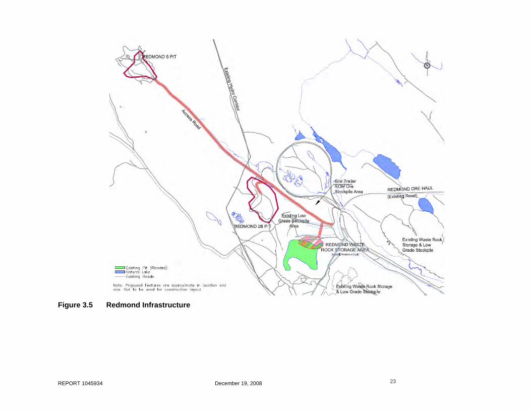
REPORT 1045934 December 19, 2008 23
Figure 3.5 Redmond Infrastructure

REPORT 1045934 December 19, 2008 24
Figure 3.6 Existing Pits (Potential Borrow Areas)

REPORT 1045934 December 19, 2008 25
Vegetation will be cleared from the area and organic material stockpiled for use in site rehabilitation. Provincial environmental legislation and regulations will be applied during borrow area development, as well as a progressive restoration plan for the site, prior to decommissioning. Specific details on establishing, using and rehabilitating borrow pits will be outlined in the EPP.
3.1.4 Mine Infrastructure
All iron ore production from the James and Redmond properties will be beneficiated at the Silver Yard Area. Figure 3.4 illustrates the proposed infrastructure at the Silver Yard Beneficiation Area and includes the following:
• Beneficiation Area, which includes the Beneficiation Building, Primary Mobile Crushing Plant, various conveyors, Product Stockpiles;
• Water Supply Tank and Pump building module;
• Electrical building module, four mobile diesel generators, and transformer;
• Diesel storage tanks and fuelling dispensing station for mobile equipment;
• Vehicle and Equipment Maintenance Shed;
• Standard mobile offices;
• Parking area;
• Raw Ore Stockpile Area;
• Stockyard and railcar loading ramp;
• Reject fines disposal pipeline;
• Stormwater Management Pond (SWM-1); and
• Security fencing and/or signage.
The infrastructure at the Redmond Mining Area includes the following and is illustrated in Figure 3.5:
• Redmond 2b Pit and associated haulage roads;
• Redmond 5 Pit and associated haulage roads;
• Redmond 2b Low Grade Stockpile;
• Redmond 5 Low Grade Stockpile;
• Redmond Raw Ore Stockpile Area; and
• Redmond Site office trailer.
Beneficiation Building and Process
The building and contents will be semi mobile and modular to fit with the Project’s long term plans. The beneficiation building will house the equipment needed for the beneficiation process. These include tumbling scrubber, secondary crushing equipment, primary screening equipment, secondary screening equipment, filtration equipment, 20T crane and various chutes, conveyors, and pumps. The beneficiation plant is designed to operate on average 212 days/year. This process description is illustrated in Figure 3.7. Details of the process flow and equipment is provided in Appendix G.

REPORT 1045934 December 19, 2008 26
Other buildings at the Beneficiation area include: mine dry, site offices and Analysis Laboratory, which will be standard mobile trailers/modular units; maintenance shed, which will be a sprung type structure; and warehouse facilities, which will be housed within containers.
Figure 3.7 Overall Beneficiation Process Flow Diagram
Other Infrastructure
The other infrastructure that will be located at the Silver Yard Area include fuel storage tanks, mobile diesel generators, transformer, laydown areas, and fire protection and process water pump building.
Fuel Storage
Fuel storage in Newfoundland and Labrador is regulated by the Storage and Handling of Gasoline and Associated Products Regulations, 1982. A Certificate of Approval for a fuel storage system must be obtained from the Department of Government Services and Lands. Fuel caches in remote areas of Newfoundland and Labrador should abide by the Environmental Guidelines for Fuel Cache Operations as stipulated by the Department of Environment and Labour.
Transportation, storage, and use of fuels at the Project site will be conducted in compliance with all relevant laws, standards and regulations. Before transporting or storing fuel at the Project site, contracted fuel suppliers will be required to provide a copy of a fuel spill contingency plan acceptable to LIM. LIM and its contractors are required to ensure that fuel and other hazardous materials are
Reject Fines slurry

REPORT 1045934 December 19, 2008 27
handled by persons who are trained and qualified in handling these materials, in accordance with government laws and regulations.
The storage tank capacity is based on 15 days diesel fuel consumption. A 500m3 Diesel Oil Storage Tank and a 45m3 Diesel Vehicle Refuelling Tank will be installed on-site. The 500m3 tank is of single wall design with retention lined dike and the 45m3 tank is a single wall design within a self contained steel basin. The 500m3 tank foundation is to be made of compacted sand and includes a geomembrane that covers the entire dike area. The dike retention volume will be able to retain at least 110 percent of the tank volume. Any water rejected from the tanks will be directed into an oil/water separator. The effluents from the oil/water separator will be disposed of as per environmental standards.
These storage tanks will be designed according to API 650. Large storage tanks will be provided with one manhole on the side wall near the bottom level. One additional manhole will be provided on the roof of the tank for closed tanks. Drums of fuel oil, if required at the site, will be tightly sealed to prevent corrosion and rust.
Electrical Power Supply
The Menihek Power Plant, owned and operated by Newfoundland and Labrador Hydro, is located 32 km SE from Silver Yard and is the only provider of electric power to the area. The plant was built to support iron ore mining and services in Schefferville. The plant contains two 5 MW Westinghouse generators and one 12 MW unit. The main substation is close to Silver Yard lowering the voltage of distribution to Schefferville town.
The existing transmission corridor runs across and adjacent to the Redmond and James properties as well as the Silver Yard area. Refer to Figure 3.1 for locations. The expected peak demand load from the beneficiation process is currently estimated at 1500kW and total connected load is 3000kW. The expected peak demand load from the dewatering is currently estimated at 2000kW and total connected load is 3000kW.
The initial phase of the Electrical Supply Plan will have power generated by up to four mobile diesel generators located at Silver Yard. These generators will be continuous duty, 750 kW, 60 Hz, and 600 V and placed on concrete pads. A mobile generator will also be required at the field trailer at Redmond. Up to four additional 900kW mobile generators will be located nearby the dewatering wells at the James site. An aerial transmission line at 4160V will distribute the power to each pump at the James Site. Local starters will control each individual pump.
As soon as it is possible, the second phase of the Electrical Supply Plan will be initiated. This phase involves drawing hydro-electric power from the existing regional power grid. A substation will be required and it is expected to be located near the Silver Yard area.
Infrastructure (2009)
For 2009, it is anticipated that the proposed beneficiation equipment and building, as described in Section 3.3.1.4, will not be operational in time for the proposed production schedule. A temporary beneficiation setup is therefore under consideration.
The temporary layout is shown in Figure 3.4. The equipment, to be supplied by a separate contractor, will include a jaw crusher (600 t/hr), belt feeder, 6 x 20 twin screen plant, 200 HP gyratory cone

REPORT 1045934 December 19, 2008 28
crusher, blade mill washer, tycan hydro-clean (for dewatering), 6 x 20 horizontal screen plant with twin screw, and a 5 x 20 horizontal dewatering screen plant.
Within the process, the raw ore would be classified into two size fractions. Materials less than 6 mm in size would be stockpiled for future processing in 2010 when the proposed beneficiation plant is operational. Materials greater than 6 mm and less than 50 mm would flow through the temporary beneficiation process to produce a washed Lump Ore product.
Dust on stockpile fines will not be an issue since it will contain 8 percent moisture. Should dust be generated from the stockpile, several procedures will be in place to prevent any environmental concerns, including spraying water, blending of piles, and consideration of turnaround time.
Water for the 2009 beneficiation infrastructure will be supplied from a nearby groundwater well. Management of the drainage from stockpiles will be done by grading and the placement of ditches which flow into Silver Yard Stormwater Management Plan (SWM-1).
The stockpiling areas for the 2009 operations, as identified on Figure 3.4, will be depleted during the 2010 operational season.
Water Supply
The Project’s proposed water supply plan is shown in Figure 3.8.
Potable Water
Potable water will be required at the beneficiation building, various site office trailers at Silver Yard, and at the site trailer at Redmond. Initially, it is anticipated that potable water will be tanked to the site and/or bottled water will be transported to the Project. The water will be stored in the potable water distribution system. It is also recognized that existing ground water testing has shown that the water is of suitable quality and so it is possible that groundwater may be considered at some point in the future. Testing of the potable water quality will be conducted regularly in accordance with provincial requirements. Potable water at the Redmond site trailer will be provided by bottled water.
Wash Water
Water for use in the beneficiation process will be sourced locally from within the project area. Groundwater sourced from the dewatering system and not used to supplement the flow in the unnamed tributary will also be diverted to the Process Water and Fire Protection Tank at a current estimated flowrate of up to 8 m3/min (2,055,000 m3/year)
Fire Water Supply
Water supply will be stored in the process water tank. The lower portion of the water tank will be reserved for firewater. The reserve volume will be a minimum of 620 m3.

REPORT 1045934 December 19, 2008 29
Figure 3.8 Preliminary Water Balance
3.1.5 Supporting Infrastructure
It is not anticipated that any permanent structures will be erected for the mining and beneficiation operations at the Silver Yard area, although some temporary stores and workshops will be established. As this will be a beneficiation site, a workshop and warehouse will be established, as well as a fuelling station nearby. A portable office and lunchroom facility will also be set up, which will include services such as washrooms and a first aid room. All of the buildings, including foundations if required, will be removed upon completion of operations. General services and infrastructures will be shared with the contractor.
Laboratory
It is planned to establish an on-site mobile laboratory in a portable modular building at the Silver Yard area. The laboratory will include a sample preparation section with a drier, crushers, screens, pulverisers and rifle splitters and an analytical lab section for daily ore control and exploration samples analysis. It is anticipated that the analytical methods used will be fusion (lithium metaborate) followed by XRF spectrometry.
Workshop
A maintenance/workshop shed (sprung type structure on concrete pad) and maintenance yard will be provided to conduct routine maintenance and non-major repairs for the mine and beneficiation

REPORT 1045934 December 19, 2008 30
operations. The building will be equipped with the necessary tools and equipment to maintain the mobile fleet. It is expected that the workshop would be equipped with compressed air and related tools, tire changing equipment, and hydraulic hose preparation. A closed-circuit wash bay and oil-water separator will be developed within the concrete-floored Maintenance Building and collected material will be pumped out on a routine basis for disposal by a licensed and experienced contractor at an approved facility. There will be no discharge of this into the surrounding environment. Solvents may be used for parts cleaning and if so, will be properly stored and disposed of accordingly.
It is anticipated that onsite storage of small retail-size quantities of hydraulic oils and other materials may be required for the limited mine vehicle/equipment maintenance. In addition, diesel storage associated with local or emergency back-up power generation may be required. Petroleum/oil/lubricant (POL) transport, storage, use and disposal will be conducted in accordance with applicable legislation and all workers will be trained in the appropriate Environmental, Health & Safety (EHS) approach to working with these materials. Spill kits will be available at key locations on site and workers will be trained in their use and other emergency response procedures.
It is anticipated that major repairs would be conducted elsewhere at the contractor’s discretion.
Warehouse
The warehouse will contain critical components for the vibrating screens and ware parts for crushers and conveyors. The contractor may want to store tires, filters, lubricants/oils and brake parts for trucks and drill steel, bits and parts for drill rigs.
Explosives Storage and Mixing Facilities
Iron ore extraction will be conducted by a Labrador-based mining contractor. Mining methods will be left to the Contractor’s discretion. Mechanical methods will be used, where possible, to break up the rock. The contractor may also require the use of explosives. The contractor will be responsible for complying with the required permit and/or approvals under the Natural Resources Canada Explosive Regulatory Division. The Contractor will ensure that blasting will follow all provincial regulations, including for Occupational Health and Safety Regulation, under the Newfoundland and Labrador Occupational Health and Safety Act 1165 and the Mine Safety of Workers under Newfoundland and Labrador Regulation 1145/96. The Contractor will hire experienced/licensed blasters.
Communication
All mining equipment and mine vehicles will be equipped with two-way radio system. This radio system will be available within the beneficiation building, maintenance building, and offices. A transmitter/receiver station including antenna tower and housing for radio communication equipment will be required. The location of the tower will be selected to optimize communication transmissions between the James – Redmond – Silver Yard sites.
Telephone and internet services would be provided through satellite services.
Site Access
Primary access to the James mineral deposit is by an existing gravel road which is located approximately 1 km southwest of the Silver Yard area. The James property straddles an existing road connecting Silver Yard with the Redmond property, and continues to the Menihek hydroelectric dam,

REPORT 1045934 December 19, 2008 31
where the road is terminated. The existing roads are in fair condition and will require brushing to improve visibility and grading to establish road surface.
The access roads will require proper signage. The signage will include posted speed limits, stop signs at intersections, and caution signs about the co-use of mine and public traffic. Adequate numbers of signs, which will be in all local languages, will be posted.
Within the pit designs, the access roads will be limited to only mine personnel. The haulage roads will be designed and built to permit the safe travel of all of the vehicles in regular service by following accepted industry standards and following Section 27 of the Mines Safety of Workers Regulations.
Although all of LIM’s properties are located in the Province of Newfoundland and Labrador, they will utilize, to some extent, present connecting roads on the Quebec side of the border and most likely some of the services available from the town of Schefferville and the surrounding communities located in the province of Quebec.
Lighting
All buildings will include sufficient perimeter lighting with outdoor fixtures. Exterior lighting will be timer or photocell controlled. Lighting will also be provided at doorways and overhead doors. There will be no street lighting on any access roads. Portable lighting plants and lights on mobile equipment will be used within the pit areas to illuminate working areas.
3.1.6 Railway Infrastructure
In order to deliver product, LIM must transport by rail, approximately 568 km to the port of Sept Îles for further shipping by marine transport. LIM will operate a short spur line linking the Silver Yard with the existing rail system. The existing rail system includes:
• a 208 km link from Schefferville to Emeril Junction (near Ross Bay Junction) that is owned and operated by Tshiuetin Rail Transportation Inc.(TSH), a company jointly owned the Innu Nation of Matimekush-Lac John, the Naskapi Nation of Kawawachikamach, and the Innu Takuaikan Uashat mak Mani-Utenam;
• the 360 km of rail from Ross Bay Junction to Sept Îles that is operated by Quebec North Shore and Lab Railway (QNS&L) a wholly owned subsidiary of the Iron Ore Company of Canada (IOC); and
• at Sept Îles, the rail link from Arnaud Junction to Pointe-Noire that is operated by Arnaud Railways, (AR), a wholly owned subsidiary of Wabush Mines.
A new Labrador Iron Mines Holdings Limited subsidiary company, LabRail, has been incorporated under the laws of Canada to operate the railway at the mine site and coordinate LIM’s rail transportation to the marine terminal in Sept Îles. Initially, LabRail will own or lease and operate the rail loading facilities and all associated rail infrastructure, rolling stock and power.
Arrangements will need to be entered into with other railroad companies regarding access and transport requirements over the various rights of way between Silver Yard and the Port. It is possible that these arrangements could also include other potential commercial and mining operations wishing to utilize some or the entire transport route. This rail facility will be available for use by other companies

REPORT 1045934 December 19, 2008 32
and will improve the commercial viability along and in close proximity to it. LabRail will cooperate in any future mineral development by others in the facility use and, if necessary, in the realignment of the line.
Existing and proposed railway infrastructure is detailed in Figures 3.9 and 3.10.
Infrastructure
A 3.5 km spur line previously operated and abandoned by IOC will be restored for use by LabRail. Including sidings to the spur line, 7,800 m of new track will be laid. The infrastructure components include:
• ballast - the existing railbed and most of the necessary ballast are already in place and some grading and levelling will be done in preparation to the laying the track. Some additional ballast will be required. This can be obtained from existing sources at the site;
• culverts - all necessary culverts are in place and require no immediate maintenance;
• ties - new hardwood creosoted track and switch ties;
• rails - new or second-hand rails;
• turnouts and switches - second-hand turnouts, new switch stand to main line;
• bumping posts and derail - used bumping post and derail; and
• other track material (OTM) - new spikes, new or used rail anchors, used tie plates and joint bars, new track bolts, nuts and spring washers.
The new track and associated infrastructure will be installed in conformance with the latest edition of the American Railway Engineering and maintenance-of-way Association (AREMA) recommended practices.
There may also be a split platform static railway scale and scale house, to weigh the loaded ore cars.
Rolling Stock
LabRail will operate with sufficient power units and rolling stock to meet the operational needs of the Project. The numbers of locomotives and ore cars will be initially determined on the start-up operations (i.e., the first year production level), and by the outcome of ongoing negotiations on railway operation). Locomotives will be SD40-2 type diesel locomotives or similar and the rolling stock will be 40-foot gondola iron ore cars with a nominal capacity of 93 tonnes of ore.
Day-to-day maintenance of the locomotives and ore cars will be conducted by LabRail. Larger maintenance requirements will be addressed by an experienced and qualified railway operator under contract to LabRail.
Storage, Loading, and Shipping
After beneficiation, saleable products will be stockpiled at the Silver Yard site and loaded into ore cars with a front end loader. The loaded cars will be hauled by LabRail to the main line and then hauled to Emeril Junction. The cars will be hauled from Emeril Junction to Sept Iles by QNS&L.
The initial operation of the Project is scheduled to produce 200,000 tonnes of ore in the first year through a haulage season of 212 days. This rate will increase over the following two years to reach 2,000,000 tonnes per year.

REPORT 1045934 December 19, 2008 33
Figure 3.9 Existing Railway Infrastructure

REPORT 1045934 December 19, 2008 34
Figure 3.10 Proposed Railway Infrastructure

REPORT 1045934 December 19, 2008 35
Regulatory Framework
LabRail will operate entirely within the Labrador and as such will be regulated under the provincial Rail Service Act 1993. The regulatory provision of this act is that the railway construction and operation must be approved by the Lieutenant-Governor in Council (Cabinet). Cabinet would then assign additional regulatory function to one or more government departments such as the Department of Transportation and Works.
LabRail will only operate within the Province of Newfoundland and Labrador and will therefore not, at least initially, be required to be designated as a Common Carrier under the provisions of the Canada Transportation Act 1996. Nevertheless LabRail will agree that it will operate as if it were a common carrier for the purposes of ensuring that other potential users of LabRail track and facilities will be granted a suitable level of service.
3.1.7 Surface Water Management
James North and James South Deposits
There are two surface water features within the James North and James South properties:
• James Creek flows along the eastern edge of the sites; and
• An unnamed tributary which originates from a spring situated between the James North and James South mine pits areas flows southeast into Bean Lake. The spring is located approximately 30 m west of the existing road crossing.
Surface water features of relevance on and in the immediate vicinity of the James Property include Bean Lake (east of site), James Creek (which flows from east of Ruth Pit to Bean Lake), and several springs that originate on the James property and form an unnamed tributary that flows southeast from the site to Bean Lake. Details regarding flows and water balances for these features are presented in Section 4.1.5. The locations of the two springs at the James deposit (James North and James South Springs) are such that they will likely be affected by pit dewatering, and since they are the source of water for the unnamed tributary, it is also likely that the unnamed tributary will be affected unless mitigation measures are put in place. A mitigation strategy to deal with this is outlined in detail in Section 4.1.5, but in summary, it will involve diverting a portion of the pit groundwater dewatering water (after settling) to the unnamed tributary to make up for the water lost from the springs. The source of the springs is groundwater and the source of the pit dewatering water will be groundwater, therefore, the mitigation strategy involves using the same source of water as is currently supplying the tributary.
Surface water collected in in-pit sumps within the James North and James South pits will be pumped to the nearby James Settling Pond area and managed separately from the groundwater dewatering system water at Settling Pond Area SP1. It is currently anticipated that this area would include two settling ponds, one for the pit water management and one for groundwater dewatering management. If on-going sampling of the water quality shows that the water within the ponds is not suitable for discharge, the water would be pumped to the Silver Yard area for use within the beneficiation process and then subsequently directed to Ruth Pit. Details of these settling ponds designs will be provided during the permitting process.

REPORT 1045934 December 19, 2008 36
Redmond Deposit
The Redmond deposit area contains isolated ponds and pits, primarily created from past mine workings. There are currently flooded abandoned mine pits on-site. There are natural small waterbodies present and a small stream is located approximately 5 km from the proposed mine operation. The stream flows in a southeasterly direction through existing abandoned ore stock piles towards Redmond Lake (Figure 4.13).
The main surface water features in the vicinity of the proposed Redmond 2B pit are a wetland/pond area located north of the proposed pit which serves as a source for a stream that runs southeast past the north side of Redmond 1 Pit and ultimately discharges into Redmond Lake. Details regarding flows in this stream are presented in Section 4.1.5. Groundwater discharge appears to be the main source of water discharging from the wetland at the headwater of this stream.
Other surface water features of note include the now flooded Redmond 1 and Redmond 2 pits, located southeast of the proposed Redmond 2B pit. The groundwater water table at Redmond is approximately 25 metres below ground surface in the proposed Redmond 2B pit area, therefore it will be some time before pit dewatering is required; however, based on the existing groundwater information it is possible that pit dewatering may affect the rate of groundwater discharge to the wetland which will affect flow in the stream. A mitigation strategy to address this possibility is presented in Section 4.1.5.
Surface water collected in in-pit sumps with the Redmond 2b and 5 pits will be pumped to the existing Redmond 2 pit.
Silver Yard
The surface drainage water from the catchment area of the beneficiation plant will be diverted to the Silver Yard Stormwater Management Pond (SWM-1), before release into the environment. The reject fines disposal pipeline and beneficiation plant emergency drainage is also located at that pond.
3.1.8 Clearance and Condemnation Work
Investigations on the old IOC stockpiles have shown that the preferred locations were near the pits/loadouts in areas underlain by rocks other than the Sokoman Iron Formation. If there was no such convenient location then stockpiles would be placed on top of the iron formation, if it were to be found uneconomic (by their standards).
Redmond 2b
Geological mapping indicates that there is a band of Wishart quartzite running northwest to southeast on the west side of the Redmond 2B deposit and this was supported in the drill holes form LIM’s 2008 drill program. The area to the west would be small with the Menihek power lines being approximately 150m away. This western location would offer an area that is approximately 150 x 200m.
The area to the north would be quite small, being hemmed in by the pit itself, the Menihek power lines and the Redmond 5 access road.
There is an existing waste rock storage pile immediately to the east of the deposit that could also be considered for stockpiling. This area is underlain by rock units other than the Iron Formation.

REPORT 1045934 December 19, 2008 37
An existing waste rock and low-grade ore stockpile is located between the Redmond 2b deposit and the existing Redmond 2 pit. Drill holes from LIM’s 2008 drill program indicate that these stockpiles are located on top of Wishart Quartzite (waste). This pile could be enlarged.
The area immediately to the west of this low-grade stockpile (and still between the 2 and 2B deposits) is an area that should be considered for future exploration and not covered over. The potential for exploration in this area was deduced from the apparent ore material in the NW wall of the Redmond 2 pit.
In addition, the mined out Redmond 2 pit could be backfilled with waste rock.
Redmond 5
The geology map shows that there is a barren northwest to southeast trending band of Wishart quartzite immediately to the east of the deposit and additional mapping will be conducted in order to determine its coverage.
There is a broad band of Iron Formation to the west of the Redmond 5 deposit which is still open for exploration and could have some potential for economic mineralization.
James North
The proposed James North waste rock storage area appears to be on top of uneconomic Fleming Formation (chert breccias), Denault Formation (dolomite) and Wishart formation (quartzite) all of which have been mapped immediately to the east of the proposed pit. This information is from IOC Geology Maps and Wardles 1982 Geology Map of the area. In addition to the geological mapping, IOC 1:40 feet scale cross sections covering the proposed area supports the uneconomic or absence of mineralization and suggests a suitable place for stockpiling. Mapping and possibly trenching/drilling could further expand this area to the north.
James South
The proposed area for the James South waste rock storage area is underlain by the Sokoman Iron Formation, which within this area is considered to be uneconomical, and is southeast along strike of the James Deposit.
There is an area south of the proposed James South pit that has a potential economic interest and as such has been avoided in the footprint for the James South Waste Rock Storage and Low-grade Stockpile area.
3.1.9 Waste Management
The objectives of waste management are to prevent, minimize, and mitigate the impact of the waste materials on the environment. The plan is to control the on-site management and final disposal of wastes during the construction and operation phases. Where and when possible, a Reduction, Reuse and Recycling policy, will be implemented to minimize waste generation.
3.1.9.1 Wastewater and Sewage
Wastewater and sewage collection will be required at the Silver Yard area and at the Redmond site. At the Redmond site, washroom facilities will be provided within a mobile trailer unit. Wastewater and
REPORT 1045934 December 19, 2008 38
sewage will be handled by underground holding tanks and transported to the Silver Yard wastewater treatment module.
At the Silver Yard area, wastewater and sewage will be handled and treated by biological oxidation of wastewater with forced air and sludge recycle. Grey water is sterilized before its final discharge at the outlet of the wastewater treatment module. After sterilization, grey water will be transferred to Ruth Pit.
During the construction phase and until the biological oxidation treatment is operational, wastewater and sewage will be collected in holding tanks, emptied by vacuum truck and disposed of at a licensed facility. All management will be conducted in accordance with applicable regulations.
3.1.9.2 Domestic and Solid Waste Disposal
There is no on-site landfill proposed for the Project. Based on ongoing discussions with the Municipality of Schefferville, it is currently planned that garbage and litter will be collected on-site and hauled and placed in a landfill facility belonging to the Municipality of Schefferville, in accordance with the applicable regulations. Any food or organic garbage onsite will be held in animal-proof containers to prevent attracting bear, birds, and other wildlife. Initial communications with the contractor for the Municipality of Schefferville landfill suggests that there is adequate landfill life and capacity to accommodate the municipal waste generated by the mine. The Municipality of Schefferville has indicated its willingness to discuss the provision of certain municipal services for the Project.
No wastes will be deposited in or near watercourses or wetlands. A recycling program is being considered for the area and LIM will support and participate in this initiative, where possible.
3.1.9.3 Hazardous Waste
It is not expected that the mine will generate large quantities of hazardous waste. Should any hazardous wastes be generated, they will be stored, transported, and disposed of according to federal and provincial waste disposal regulations.
LIM will require contractors to follow provincial waste diversion regulations or policies, including provincial programs for beverage containers, tires and waste oil and other petroleum products. Discarded tires will be handled according to the requirements of the provincial tire recycling program established by the Waste Management Regulations and used oil will be collected for recycling or reuse according to the Used Oil Control Regulations. In addition, any scrap metals will be taken to a scrap metal recycling operation.
3.1.9.4 Beneficiation Plant Waste Effluent
The production of the “direct shipping” ore requires only a simple process of crushing, screening, and washing. Effluent originating from the beneficiation area will contain rock fines but will have no chemical constituents. Current mine plans anticipate that the washwater will be directed into existing mine pits to settle out solids. Current baseline information, including a preliminary aquatic habitat assessment indicates that the abandoned pits have no surface connectivity to existing fish habitat. Further to recent discussions with regulators (DFO, February 2008), the 2008 baseline program has provided additional confirmation that the existing pits do not contain self-sustaining fish communities.
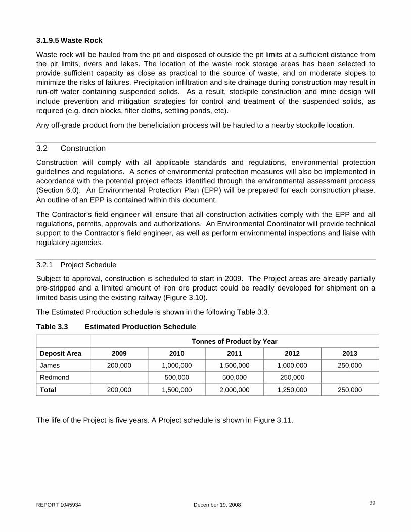
REPORT 1045934 December 19, 2008 39
3.1.9.5 Waste Rock
Waste rock will be hauled from the pit and disposed of outside the pit limits at a sufficient distance from the pit limits, rivers and lakes. The location of the waste rock storage areas has been selected to provide sufficient capacity as close as practical to the source of waste, and on moderate slopes to minimize the risks of failures. Precipitation infiltration and site drainage during construction may result in run-off water containing suspended solids. As a result, stockpile construction and mine design will include prevention and mitigation strategies for control and treatment of the suspended solids, as required (e.g. ditch blocks, filter cloths, settling ponds, etc).
Any off-grade product from the beneficiation process will be hauled to a nearby stockpile location.
3.2 Construction
Construction will comply with all applicable standards and regulations, environmental protection guidelines and regulations. A series of environmental protection measures will also be implemented in accordance with the potential project effects identified through the environmental assessment process (Section 6.0). An Environmental Protection Plan (EPP) will be prepared for each construction phase. An outline of an EPP is contained within this document.
The Contractor’s field engineer will ensure that all construction activities comply with the EPP and all regulations, permits, approvals and authorizations. An Environmental Coordinator will provide technical support to the Contractor’s field engineer, as well as perform environmental inspections and liaise with regulatory agencies.
3.2.1 Project Schedule
Subject to approval, construction is scheduled to start in 2009. The Project areas are already partially pre-stripped and a limited amount of iron ore product could be readily developed for shipment on a limited basis using the existing railway (Figure 3.10).
The Estimated Production schedule is shown in the following Table 3.3.
Table 3.3 Estimated Production Schedule
Tonnes of Product by Year
Deposit Area 2009 2010 2011 2012 2013
James 200,000 1,000,000 1,500,000 1,000,000 250,000
Redmond 500,000 500,000 250,000
Total 200,000 1,500,000 2,000,000 1,250,000 250,000
The life of the Project is five years. A Project schedule is shown in Figure 3.11.

REPORT 1045934 December 19, 2008 40
Figure 3.11 Project Schedule
3.2.2 Site Preparation
Clearing
Trees and shrubs will be cleared with chain saws or other hand-held equipment. Mechanical clearing methods may be used in areas where terrain disturbance will not cause topsoil loss or sedimentation of watercourses and waterbodies.
Vegetation clearing (e.g. trees and shrubs) will be required in advance of some access road construction, building construction, pit development, and other site preparation activities. Refer to Figures 3.12 and 3.13 for extent of area. It is anticipated that there is no merchantable timber within the areas of clearing. Prior to site clearing, a professional biologist will be retained to identify any migratory bird nests and recommend and apply a buffer around them. Any tress that are large enough will be salvaged and cut for firewood and/or put through a chipper, the chips will then be used to help revegetate areas in the future. The remaining will be burnt or mulched.
All work will be carried out following all applicable government legislation including the Forestry Act and Cutting of Timber Regulations.

REPORT 1045934 December 19, 2008 41
Grubbing and Debris Disposal
Grubbing of the organic vegetation mat and/or the upper soil horizons will be limited to that necessary to meet the Project engineering requirements. Topsoil and organic materials will be stockpiled and used in site rehabilitation.
A minimum 15 m buffer zone of undisturbed natural vegetation will be maintained between watercourses and areas of grubbing activity. If specific site conditions require modification to the buffer zone, this will be undertaken in consultation with the DFO Area Habitat Biologist.
All work will be carried out according to the environmental protection measures for vegetation clearing and grubbing documented in applicable government legislation including the Forestry Act and Cutting of Timber Regulations
Following release from the environmental assessment process, and once all the required government permits have been received, the construction phase would be initialized. General construction will employ best practices, incorporating and following the guidelines provided in “Environmental Guidelines for Construction and Mineral Exploration Companies”.
Pre-Stripping
Grubbing of the organic vegetation and/or the upper soil horizons will be kept to the minimum but is necessary within the Project footprint. Erosion control techniques and devices will be used to stabilize easily eroded areas. Topsoil and overburden will be stored in separate stockpiles for later use in reclamation activities.
Figure 3.12 Extent of Vegetation Clearing, James

REPORT 1045934 December 19, 2008 42
Figure 3.13 Extent of Vegetation Clearing, Redmond
Any unsuitable material will be placed in an approved stockpile area. Runoff of sediment-laden water during grubbing will be minimized by using measures such as settling ponds, ditch blocks, interception ditches and filter fabrics. Erosion control measures such as rip-rap, filter fabrics, drainage channels, and gravel or wood chip mulches will be implemented in areas prone to soil loss. Erosion and Sediment Control measures will be installed in accordance with manufacturer’s recommendations. These features may include, but are not limited to, silt fencing, sediment control ponds, and gabion blankets. All work will be in accordance with the EPP.
Site Preparation Activities for Beneficiation Plant and Railroad Facilities at Silver Yard
The Silver Yard area is the location of the railway marshalling yard previously operated by IOC. With minor exceptions, the original railway subgrade and track ballast remains in place although the steel tracks were removed sometime after IOC terminated its mining operations in 1982. The LIM beneficiation plant will be located in the Silver Yard area and related disturbance of the natural environment will be managed to limit the overall size of the facilities footprint. Some of the more prominent structures will include the beneficiation building itself, along with related support infrastructure such as finished product stockpiles, run-of-mine ore stockpiles, laydown yards, office facilities, plant access roads, the railroad marshalling yards and associated ore car loading facilities. Further details of the infrastructure are provided in Section 3.1.4.
Excavated volumes have been utilized to backfill areas required for ore stockpile pads, the rail car loading ramp, site access roads, etc. When cut and fill volumes are balanced, a total of only 15,000 cubic meters will need to be borrowed (from James deposit area). That is, there will be no net surplus of excavated material from the Silver Yard site preparation.

REPORT 1045934 December 19, 2008 43
Topsoil material salvaged from the Silver Yard site preparation will be stockpiled around the site for future reclamation purposes. These areas will be seeded to provide stability to the stockpile.
The James Property requires clearing and grubbing within the waste rock storage and low-grade stockpile footprints and pit footprints. The Redmond Property requires minimal clearing and grubbing within the possible low-grade stockpile footprint. No clearing and grubbing is required for the waste rock dump storage option. Stripping within the pit footprints has already been done by IOC during previous mining operations. Suitable reclamation material from the clearing and grubbing will be stockpiled in strategic locations for future reclamation purposes.
3.2.3 Construction Infrastructure and Activities
Construction within the Project area will involve the following activities:
• transporting equipment, construction materials and related supplies to construction sites, including transporting, storing and handling hazardous materials, fuels, lubricants and explosives;
• establishing and operating laydown areas;
• excavating, including disposing of excess waste rock and overburden
• establishing and operating borrow pits, including identifying sources of borrow material;
• railway construction;
• installing watercourse crossing structures, and activities in and around watercourses; and
• erection of buildings for wash plant, maintenance shop, and other buildings (offices, lab, etc.) – note that these buildings will be of temporary/portable structure complying with appropriate building codes etc.
• site rehabilitation and environmental monitoring.
Power supply during the construction phase will be by diesel generators and will be supplied by the contractors conducting the work.
It is anticipated that there will be no blasting required for any of the construction activities.
There are no upgrades planned for the haul road to Redmond, with the exception of minor maintenance. Material will sourced from the James and Redmond waste rock.
Excavations during the construction phase will include excavating in the following areas: primary crusher, settling and stormwater management pond. The expected vehicle types during construction include dozers, graders, rear-dump trucks, hydraulic shovels, boom trucks, and pick-up trucks. The expected hours for equipment use during construction range from 300 hours to 2,000 hours.
Construction activities are expected to be conducted on both day shift and night shifts.
Construction Yard Areas
A construction trailer yard has been provided for in the site layout design. The yard covers an area of approximately 75 m x 50 m. The yard will include a number of standard mobile trailers and a gravel parking area for 50 vehicles. Adjacent to this yard will be a construction material and equipment lay down yard. The lay down yard will be approximately 75 m x 50 m. These yards are more than 50 m

REPORT 1045934 December 19, 2008 44
from any natural waterbody. These yards will remain after construction and be used as additional lay down areas for the operational phase.
Truck Routes
Road traffic during construction will include deliveries of material from the nearby train station. Materials will include steel, concrete, and equipment. Vehicles and equipment will follow established routes when travelling to or from the site. All entrances and exits to the site will be designed so that incoming and outgoing vehicles may merge safely with other traffic, and oversized modules will be provided with escorts as required. A traffic control plan will be created for the Project. Hazardous materials will be transported and stored as required by the supplier’s MSDS sheet.
Sources of Aggregate
The aggregate required for the concrete will be sourced locally. All other aggregates required for the construction will be taken from the excavation material on-site or from waste rock at the mine.
The waste rock from the James and Redmond sites will generally be acceptable for use in road building and maintenance. The onsite mobile crushing plant would be used to create acceptable crushed material.
As indicated in Section 3.1.3, there are existing excavations in close proximity to the Project that are identified as sources of acceptable material.
3.2.4 Pit Dewatering
James Property
The water drawn from the proposed dewatering wells around the James pit is estimated to be discharged at a rate up to 113 m3/min (SNC 2008). This flowrate is based on early calculations and limited data and is considered to be very conservative. Currently, it is proposed to have dual filters at the dewatering pump outlets with one dual filter per two pumps. These filters will treat the groundwater by removing the sediment prior to discharging to the natural environment. A settling pond (Settling Pond Area SP1) will also be constructed to provide additional settling/retention time, as required.
A small quantity of water will be discharged to the unnamed tributary and the remaining majority of water will be directed to the Silver Yard for use in the beneficiation process, discharged to Bean Lake, and/or via James Creek. The preferred location for the large quantity outlet will be designed during the detailed design phase.
The settled (removal of suspended solids by settling/filtering) pit dewatering water, which will be discharged to the south portion of James Creek near where the creek discharges into Bean Lake. Measures will be put in place to minimize any potential erosion or hydraulic effects from this discharge. The stream bed is rocky in this area so erosion is not likely, however the flow will be discharged over a diffuser bed before entering the creek as an additional erosion control measure.
Further discussions on dewatering activities are presented in Section 3.3.5.
Redmond Property
Pit dewatering water from the Redmond 2B and 5 pits will be pumped to either the Redmond 2 or Redmond 1 pit for settling. This water will then drain to the unnamed stream that runs from the north of

REPORT 1045934 December 19, 2008 45
Redmond 2 to Redmond Lake. Dewatering rates for Redmond 2B and 5 have not been determined yet, but based on the flow data obtained over the course of the spring, summer, and fall of 2008 and the stream profile; it appears this stream is capable of handling significant flows.
3.2.5 Housing and Transportation
The majority of the workers for construction and operation phases will be accommodated at three existing off-site outfitter camps located at Squaw Lake, approximately 3 km from Silver Yard. These camps have single-room accommodations for up to 80 workers, and provide a restaurant, bar and recreation facilities. A small number of workers will be accommodated in existing available facilities in the nearby town of Schefferville.
Workers will be transported to and from the work site, at the Silver Yard, by buses/vans/pickup trucks.
There will be no requirement for food handling at the Project site as meals would be supplied at the off-site camp facilities.
3.2.6 Predicted Construction Emissions and Discharges
As discussed in Section 3.2, construction activities at the site will include railway track installation, railbed grubbing, the clearing/grubbing for site services area, and the erection of buildings. All construction activities would occur in the short-term and potential emissions would be generated from tail pipe emissions from the vehicles (combustion emissions such as NOX, CO, and SO2), combustion emissions from diesel generators, and from fugitive dust due to earth moving activities and vehicle traffic.
Heavy construction activities at the site will include erecting the main crushing building, the placement of the required generators, boilers, and tanks, and the installation of conveying systems and rail lines. Emissions during construction are expected to occur intermittently over the duration of the construction period as opposed to emissions during operation, which will occur continuously. Also, the amount of fugitive dust emitted due to operational activities (crushing, ore loading/unloading, conveying, and stockpile erosion) will be greater than those observed during construction activities. Therefore, the maximum emissions during operation provide a conservative envelope for those occurring during construction.
Fugitive dust emissions during construction can occur due to land clearing, ground excavation, and equipment traffic on site.
Generally, fugitive dust emissions are:
• proportional to the disturbed land area and the level of construction activity;
• limited to periods of the day and week when the construction activities take place; and,
• vary substantially from day to day with varying meteorological conditions.
Fugitive dust emissions during construction are expected to be localized in extent, limited in duration, and smaller in magnitude than those occurring during operation. Fugitive dust emissions can be minimized by considering mitigation measures such as dust suppressants (e.g., water) on vehicle haul routes, tire washes, operational controls, and other control measures such as landscaping screens.

REPORT 1045934 December 19, 2008 46
Emissions due to fossil fuel combustion are also expected to occur during construction in the beneficiation area through the use of diesel generators and as tail pipe emissions from on-site traffic. As is the case for the fugitive dust releases, emissions including nitrogen oxides (NOX), carbon monoxide (CO), particulate matter (PM), and sulphur dioxide (SO2) are expected to be localized in extent, smaller in magnitude, and will occur for shorter durations than the potential emissions during operation. The model method for this study is described in Appendix H.
3.2.7 Site Rehabilitation and Monitoring
LIM is committed to progressive site rehabilitation during the construction and operation phases of the Project. Progressive rehabilitation is defined as rehabilitation completed, where possible or practical, throughout the mine development, construction and operation stages, prior to closure. This includes activities that contribute to the rehabilitation effort that would otherwise be carried out at mine closure.
All aspects of mine development including mine design, infrastructure location and design, and operations planning have and will be conducted with full consideration of available progressive rehabilitation opportunities and closure rehabilitation requirements. Baseline environmental studies conducted prior to site construction works will continue, or be revised as required, through the mine development and construction stage. The Project has been planned and designed to minimize the disturbed area of the site, to incorporate areas disturbed by previous mining activities where possible, and to minimize the environmental impact prior to mine operations. As such, there is little opportunity to complete progressive rehabilitation during mine development and construction.
A comprehensive environmental monitoring program will be conducted as part of the mine development and this data will be utilized to evaluate the progressive rehabilitation program on an ongoing basis.
3.2.8 Employment
Occupations during the construction phase, including NOC-2006 codes, are presented in Table 3.4.

REPORT 1045934 December 19, 2008 47
Table 3.4 Construction Phase Employment POSITION NUMBER NOC
Lead Foreman 2 721 Surveyor 2 2254 Equipment Operator – heavy 5 7421 Equipment Operator - Light 2 7421 Truck Drivers 8 7411 Labourers-specialized 3 7611 Labourers 3 7612 Carpenter 5 7215 Carpenter - helper 2 7611 Welders 5 7265 Electricians 5 7241 Electrical Helpers 5 7611 Crane Operator 1 7371 Millwrights 3 7311 Millwright Helpers 2 7611 Boilermakers 2 7262 Boilermaker Helpers 2 7611 Ironworkers - steel reinforcement 4 7264 Ironworkers - steel reinforcement-helper 2 7611 Cement Finishers 2 7282 Cement Finishers-helpers 1 7611 Structural Steel Workers 8 7263 Structural Steel Workers-Apprentice 2 7611 Bricklayers 3 7281 Bricklayers-helper 3 7611 Roofer 1 7291 Roofer-helper 1 7611 Sheet Metal Worker 2 7261 Sheet Metal Worker - helper 2 7611 Pipe Fitters 6 7252 Pipe Fitters-helpers 4 7611 Insulators 4 7293 Insulators-helpers 2 7611
TOTAL - CONSTRUCTION 104
3.2.9 Goods and Services
The construction phase of the Project will see the procurement of a wide range of goods and services. The following provides a list of some of the expected services and goods required:
• Earthworks contract which includes work for clearing, grubbing, site preparation, fencing and excavating. This would also include various goods required as part of the service contract for example, fencing supplies.
• Mining pre-stripping
• Heavy equipment rental (excavators, loaders, haul trucks, dozers, graders, etc.)
• Electrical and mechanical contracts and related supplies. (e.g. switchgears, hydro poles, wire).

REPORT 1045934 December 19, 2008 48
• Building contract (mobile trailers, maintenance shed structure)
• Beneficiation building construction contract, which will involve concrete, structural steel and mechanical components.
• Beneficiation equipment (primary crusher, secondary crusher, vibrating screens, scrubber, chutes, conveyors, pumps, fire pumps, compressors)
• Automation goods
• Welding and machining services
• Concrete goods for various pad foundations
• Crane services
• Piping contract
• Drilling contracts (dewatering wells, water wells)
• Dewatering wells supplies, including but not limited to pumps, pipelines,
• Rail bed preparation
• Clear cutting
• Miscellaneous tools and small equipment
• Holding tanks (e.g. Bulk fuel storage, day storage tank, water tank)
• Track installation rail ties, switches and other track materials
• Water Treatment System (bio-oxidation)
• Environmental services
• Erosion and sediment control features
• Laboratory building and equipment
• Fuel and refueling services
• Hotel accommodations and catering services
• Taxi, car rental, and air services
• Accommodation services
• Signage – road signs, rail signaling
• Light Vehicles
• Two-way radio repeater communication system, radios
• Computers, office furniture
• Garbage disposal service
3.2.10 Newfoundland and Labrador Benefits Strategy
As is detailed in its Benefits Policy (Section 2.2), LIM is aware of the importance of the Project to the people of the Province of Newfoundland and Labrador and is committed to the delivery of associated

REPORT 1045934 December 19, 2008 49
benefits, including education, training, and economic development, to the existing communities in Labrador. LIM is also committed to the principles of local procurement of supplies and services.
Consistent with this Policy, LIM will ensure residents of and companies based in the Province receive full and fair opportunity and first consideration for employment and business respectively, where practically and commercially achievable on a competitive basis and in accordance with the Impact Benefits Agreement entered into with the Innu Nation of Labrador.
In support of this commitment:
• LIM and its contractors will include a copy of the LIM Benefits Policy in all Project calls for expressions of interest, requests for proposals, and contracts.
In addition, LIM will:
• Liaise with provincial, and especially Labrador, educational institutions and human resources agencies so that they are informed about employment requirements and plans;
• Liaise with provincial, and especially Labrador, business groups and economic development agencies so that they are informed about goods and services requirements and plans;
• Monitor the Project labour force to establish the percentage of positions held by residents of the Province;
• Monitor the award of Project contracts to establish the percentage of the work, by value, awarded to companies based in the Province;
• On an annual basis, compile the above monitoring data, assess them relative to Project benefits targets and, if necessary, review and revise its benefits approach, initiatives and targets;
• Make the above annual compilation of benefits data available to government departments and agencies, upon request; and
• Implement the provisions of LIM’s Project Women’s Employment Plan.
The initial targets with respect to Project employment and contracting are specified and explained in Section 6.3. This section also discusses the nature, scale and duration of employment and business opportunities,
3.3 Operation and Maintenance
3.3.1 Operation and Maintenance Activities
The operation schedule will likely begin towards the end of April of each year and continue through to mid November, operating 24 hours per day. All operation and maintenance activities will be undertaken through separate contractors.
3.3.1.1 Excavation
The product will initially be excavated at 3,000 t/day per deposit site. It is anticipated that excavation will be conducted with the following types of mobile equipment:
• Komatsu WA600 loader (or equivalent); and,
• Komatsu PC800, PC750, PC400 type excavators (or equivalent).

REPORT 1045934 December 19, 2008 50
3.3.1.2 Haulage
James ore and waste will be hauled with Komatsu HD605 type off-highway trucks. Redmond waste will be hauled with the same type of truck. Redmond ore will be hauled from the pit by Komatsu HD605 type off-highway trucks and stockpiled outside the pit. The raw ore will be reclaimed with a wheel loader or shovel and loaded into large road trains (45T) and hauled to the beneficiation area.
3.3.1.3 Drilling and Blasting
Drilling will occur for both ore quality control and for blasting purposes. Based on historic experience in the area, the drill pattern size for blasting is expected to be a 7.5 – 9 m square pattern. Blasting at James and Redmond will be episodic as the deposits are softer in nature and may be excavated without much blasting, although provisions for blasting will be available. It is planned that blasting will be done with packaged/cartridge type explosives. Table 3.5 depicts the expected equipment types and numbers:
Table 3.5 Equipment Types and Numbers Equipment
Type Number of Units
Year 1 Year 2 Year 3 Year 4 Year 5 Wheel Loader 2 2 2 2 1 Mine Truck (Off-highway)
4 6 6 6 3
Track Dozer 1 2 2 2 1 Motor Grader 1 1 1 1 1 Haulage Truck 0 0 10 15 5 Blaster Truck 1 1 1 1 1 Explosive Truck 1 1 1 1 1 Pick Up Trucks 5 5 5 5 3 Fuel/Lube Truck 1 1 1 1 1 Drill Rig 1 1 1 1 1 Water Truck 1 1 1 1 1
3.3.1.4 Processing
The processing or beneficiation activities were presented in Section 3.3.1.4.
3.3.1.5 Product Export
The finished products of Lump Ore and Sinter Fines ore will be exported to markets outside of Canada.
3.3.1.6 Rock Fines Disposal
As presented in detail in earlier sections, the reject fines from the beneficiation process will be directed by pumping to Ruth Pit (see Section 3.1.9).
3.3.1.7 Maintenance Activities
A maintenance shed (sprung type structure on concrete pad) and maintenance yard will be provided to conduct routine maintenance for the mine and beneficiation operations. The building will be equipped with the necessary tools and equipment to maintain the mobile fleet. The building will have a concrete foundation and closed-circuit wash bay and a oil-water separator which will be emptied by a licensed contractor on a routine basis and managed in accordance with applicable regulations. Small retail

REPORT 1045934 December 19, 2008 51
quantities of solvents may be used for parts cleaning and if so, will be properly contained, stored and disposed of accordingly.
It is expected that major repairs will be conducted off site at a location left to the Contractor’s discretion.
3.3.2 Operation Air Emissions
Potential emissions during operation are expected to be similar to those described in Section 3.2.6 for construction and include the products of combustion, such as NOX, CO, PM and SO2, from diesel generators and onsite traffic, and fugitive dust from ore loading/unloading, crushing, and stockpile erosion. The following subsections provide a summary of the anticipated emissions during operation. The model method for this study can be found in Appendix H.
3.3.2.1 Emissions from Beneficiation Facility
Diesel generators will be used continuously on-site to provide power for the on-site equipment. Fuel oil powered boilers will be used to provide process water. Emissions from combustion arise from the burning of fuel and are dependent on fuel flow rate, fuel type, combustion equipment and the efficiency of pollution control devices. The primary products from combustion include nitrogen oxides (NOX), sulphur dioxide (SO2), carbon monoxide (CO), and particulate matter, which include both visible and non-visible emissions. Nitrogen oxide formation can be directly related to the high pressures and temperatures observed during the combustion process. Other emissions, including various hydrocarbons, CO, and PM, are primarily the result of incomplete combustion.
Standard techniques were used to estimate emissions which included using design specifications for the generators and boilers, along with accompanying emissions factors from the US EPA, to estimate potential emissions due to diesel and fuel oil combustion.
3.3.2.2 Fugitive Dust
Fugitive dust emissions at the site will occur from several different sources during operation. Potential sources include ore loading/unloading, ore crushing, stockpile erosion and dust from conveyor systems around the site. Potential fugitive dust emissions at the site were estimated using emissions factors from the US EPA AP-42 guidance documents.
See Section 3.2.6 for characterization of fugitive dust emissions.
Fugitive dust emissions from loading and unloading operations depend on the parameters of the storage pile being disturbed. Emissions due to stockpile wind erosion are highly dependent on local wind speeds and precipitation levels at the site, along with the type of material and its erosion potential. Larger aggregate material will have a tendency to form stable stockpiles, while finer material will erode over time.
Emissions from ore crushing and conveying depend on the amount of material being processed as well as the controls in place. Emissions control from the crushing operation at the site includes the use of a dust control system (baghouse) which will limit emissions from the main processing building. Emissions from conveyors were estimated with no controls; however, covered conveyors may also be used to limit fugitive dust emissions during transport to and from the various storage piles at the site.

REPORT 1045934 December 19, 2008 52
On-Site Traffic
Potential emissions from on-site traffic sources may include tail-pipe emissions due to fossil fuel combustion and fugitive dust. Emissions from combustion arise from the burning of fuel and are dependent on fuel flow rate, fuel type, combustion equipment and the efficiency of pollution control devices. The primary products from combustion include nitrogen oxides (NOX), sulphur dioxide (SO2), carbon monoxide (CO), and particulate matter (PM). Fugitive dust emissions due to on-site traffic would be proportional to the amount of property disturbed and the frequency of disturbance. Neither the tail-pipe emissions nor the fugitive dust emissions from on-site traffic are considered substantive compared to the other activities occurring at the facility during operation.
Locomotive Emissions
Combustion emissions are expected from the diesel locomotive used for transporting ore from the beneficiation area. Similar to on-site traffic emissions, emissions from combustion arise from the burning of fuel and are dependent on fuel flow rate, fuel type, and the type of combustion equipment. The primary products from combustion include nitrogen oxides (NOX), sulphur dioxide (SO2), carbon monoxide (CO), and particulate matter (PM).
Due to the infrequent nature of the source at the site (one trip is expected per day), emissions from the locomotives used on-site are not considered substantive compared to the other activities occurring at the facility during operation.
3.3.2.3 Emissions from Ore Hauling from Mine Site to Beneficiation Area
Emissions from the ore hauling activities are similar to the potential emissions due to on-site traffic as discussed above. Potential emissions may include tail-pipe emissions due to fossil fuel combustion and fugitive dust emissions.
Dust emissions would occur along the haul routes between the James or Redmond mine areas and the beneficiation area. These are all existing dirt roads and would be prone to dust emissions from any type of vehicle traffic. When a vehicle travels along an unpaved road, the vehicle’s wheels travelling on the road generate dust which is then lifted and exposed to passing winds.
Emissions due to ore hauling were estimated using standard techniques including equations found in the US EPA’s AP-42 guidance documents. Fugitive dust emission estimates varied from 221 – 325 kg/day for the one kilometre hauling route between the James deposit and the beneficiation area and 2869 – 4225 kg/day for the thirteen kilometre hauling route between the Redmond deposit and the beneficiation area.
Particulate matter emissions from the ore hauling trucks travelling on a small on-property section of roadway (approximately 250 m) were estimated for use in the air dispersion model.
3.3.2.4 Emissions from Mining
Potential emissions due to the mining operations at the James and Redmond deposits include fugitive dust from loading and blasting operations and combustion gases from vehicles.
Fugitive dust emissions from loading operations depend on the condition of the storage piles being disturbed. When freshly processed material is loaded onto a pile, there is a greater potential of fine particulate emissions. Over time, as the pile is weathered, or if the material has high moisture content,

REPORT 1045934 December 19, 2008 53
potential emissions will be greatly reduced. Other factors influencing fugitive dust emissions during loading and unloading include the frequency of the operation and the local meteorological conditions, including wind speed, humidity, precipitation, and temperature.
The removal of ore and surrounding waste rock involves drilling and blasting. A dust cloud is produced during blasting. Due to the nature of open pit mining, the dust cloud will partially be retained in the pit, although some portion of it will rise out into the local surroundings. However, it should be noted that the elevated levels of particulate matter will be limited in spatial extent and short lived, as the majority of the fugitive dust will settle within a short distance (i.e., contained within the pit).
3.3.3 Operation Discharges
Disposal and treatment of discharges is presented in Sections 3.1.9 and 3.3.5.
3.3.4 Chemical Storage/Management
The beneficiation process does not require the use of any chemicals or reagents. XRF with lithium metaborate as a flux to produce glass disk will be used for Ore Control. Procedures for safe and appropriate handling will be developed using WHIMIS and MSDS.
3.3.5 Water Management
3.3.5.1 James Deposit
The pit dewatering rate from James pits has been estimated to be up to 113 m3/min. The estimated wash water use rate in the beneficiation process is up to approximately 8.4 m3/min, the source of which could be diverted from the pit dewatering volume. The water required to make up water potentially lost from the springs feeding the unnamed tributary can also be diverted from the pit dewatering volume. The net effect of this is that more water will be sent to Bean Lake (as a result of groundwater pumping) than currently flows into Bean Lake from surface water and groundwater inputs. Information provided in Section 4.1.5 indicates that Bean Lake is capable of accommodating this additional flow without major hydraulic effects.
The water quality of the groundwater (details in Section 4.1.6) indicates that at least initially the pit water and water from the perimeter dewatering wells may contain elevated Total Suspended Solids and metals such as iron, copper and zinc. The dissolved metals concentrations were very low in the groundwater; therefore, effective water treatment should be achieved using settling/filtering water treatment methods. It is proposed to install a filtering system for the dewatering pumps, as well as constructing a settling pond at Settling Pond Area (SP1). Based on surface water quality monitoring results to date, it is likely that the water from the perimeter dewatering wells will clear up over time as the wells become highly developed. This will lead to a further improvement in water quality.
3.3.5.2 Redmond Property
The dewatering rates have not been fully determined yet for the Redmond pits, however there will be no net loss of water from this system because whatever water that may potentially be lost from the headwater of the stream from dewatering effects will be made up when this pit dewatering water is settled in either the Redmond 2 or Redmond 1 pits and is discharged back into the stream. The net effect of dewatering will be more water supplied to the stream and ultimately to Redmond Lake.
REPORT 1045934 December 19, 2008 54
3.3.5.3 Wash Water
Water requirements are modest, with the beneficiation process water (wash water) being drawn from groundwater wells. The water balance flows were estimated from similar process plants. The flows in the water balance are typical for average conditions for a wash plant producing 2 Mtpy of direct shipping product. The reject fines slurry concentration was assumed to be 21 percent by weight. There will be a number of pumps required which will maintain a distribution of water within the beneficiation process and have enough capacity to allow for surge conditions such as plant start-up or line flushing.
Fresh clear water will be required for gland water use, potable water, fire water and miscellaneous users. Occasionally the process water reservoir may have a deficit of water which will have to be made up of fresh water. However the overall average water balance does not require fresh water for process water make-up. Fresh water will be supplied from similar groundwater wells. Water for dust suppression will come from beneficiation plant fresh water.
3.3.5.4 Sanitary (Non-Potable) Water System
Storage and management/disposal of sanitary wastewater and greywater will be conducted in accordance with applicable legislation. Wastewater and sewage will be handled and treated by biological oxidation of wastewater with forced air and sludge recycle. Grey water is sterilized before its final discharge at the outlet of the wastewater treatment module. After sterilization, grey water will be directed to Ruth Pit.
It is estimated that the flowrate from the sanitary water system will be 8,000 L/day.
3.3.5.5 Potable Water
Potable water will be required at the beneficiation building, various site office trailers at Silver Yard, and at the site trailer at Redmond. Initially potable water will be tanked to the site and/or bottled water will be transported to the Project area. The water will be pumped untreated to the potable water distribution system. Existing ground water testing has shown that the water is of suitable quality and therefore, groundwater use for drinking water may be considered at a future date. Testing of the potable water quality will be conducted regularly. Potable water at the Redmond site trailer will be provided by bottled water.
3.3.5.6 Dewatering Water
Dewatering at the James deposit will be conducted using a combination of perimeter dewatering wells and inpit sumps. The water from the inpit sumps will be directed to a settling pond separate from the perimeter well water settling pond at the SP1 settling pond area. The Redmond dewatering system is planned to consist of perimeter wells and inpit sumps which will direct water to one of the historical pits in the vicinity which have undergone confirmation of the absence of permanent fish habitat.
3.3.6 Progressive Rehabilitation
Once the Mines advance from the development stage to the operational stage, progressive rehabilitation activities can commence. Progressive rehabilitation is defined as rehabilitation completed, where possible or practical, throughout the mine operation stage, prior to closure. This includes activities that contribute to the rehabilitation effort that would otherwise be carried out at mine closure. Progressive rehabilitation opportunities identified for this Project include:

REPORT 1045934 December 19, 2008 55
• Rehabilitation of any construction-related buildings and laydown areas;
• Rehabilitation of the Waste Rock Storage stockpiles;
• Development and implementation of an integrated Waste Management Plan;
• Rehabilitation, if required, of exploration drilling sites;
• Re-vegetation studies; and
• Some backfilling of selected existing open pit areas left by previous mining operations.
A comprehensive environmental monitoring program will be conducted as part of the mining operations and this data will be utilized to evaluate the progressive rehabilitation program on an ongoing basis. Additional studies, such as revegetation trials, will be conducted over the operational phase of the mine which will be integrated into ongoing progressive rehabilitation activities and will be used in the development of the final closure rehabilitation design.
Part of the rehabilitation and closure activities conducted during mine operations will include scheduled review and updates of the Rehabilitation and Closure Plan, as required. These scheduled reviews will incorporate any new or revised data gained from operating experience, progressive rehabilitation activities, environmental monitoring, and rehabilitation-related operational studies.
3.3.7 Employment
The Project operation phase employment by occupation, including NOC-2006 code, is presented in Table 3.6.
Table 3.6 Operation Phase Employment Positions Number NOC Code
Mine Operations Mine Operation Foreman 1 8221 Foreman 2 8221 Drill Operator 2 7372 Blaster 1 7372 Blaster Helper 1 8411 Loader Operator 2 7421 Haulage Truck Operator 6 7411 Dozer Operator 2 7421 Grader Operator 2 7421 Sampler 2 8614
Subtotal 21 Mine Engineering
Mine Engineer 1 2143 Mine Technician 1 2212 Surveyor 2 2254 Draftsman CAD 1 2253
Subtotal 5 Beneficiation Operation
Plant Manager 1 0721 Process Technician 1 2243 Chemical Technician (Lab) 2 2211 Environmental Engineer 1 2131 Labourer 1 7612

REPORT 1045934 December 19, 2008 56
Positions Number NOC Code Administrative Assistant 1 1441 Warehouse Person 2 1472 Maintenance Foreman 1 7211 Utility Crew (pipeline, pumps, etc.) 1 Primary Crusher Operator 4 9411 Secondary Crusher Operator 2 9411 Secondary Crusher Helper 2 9611 Belt Filter & Load-out Operator 4 9411 Mechanic 1 7312 Mechanic Helper 1 7612 Electrician/Instrumentation 1 7241 Railway & Yard Locomotive Eng. 1 7361 Railway Yard Worker 3 7432 Railway Track Maintenance Worker 1 7432
Subtotal 31 Owner Management
General Manager 1 0721 Geologist 2 2113 Mine Engineer 1 2143 Innu Liaison 1
Subtotal 5 Contractor Management
General Manager 1 0711 Secretary 1 1241 Bookkeeper/Accountant 1 1231
Subtotal 3 TOTAL - OPERATION 65
3.3.8 Goods and Services
The operation phase of the Project will see the procurement of a wide range of goods and services. These include, but not limited to, the following:
• Mining operations contract
• Beneficiation operation and maintenance contract
• Heavy equipment maintenance contracts
• Fuel
• Blasting (services and supplies)
• Accommodations services (Offsite camp facilities)
• Taxi, car rental, and air services
• Welding and machining services
• Mechanical and electrical services
• Crane services
• Dewatering drilling contract
• Pumps (for dewatering)

REPORT 1045934 December 19, 2008 57
• Mobile diesel generators
• Erosion and sediment control features
• Environmental services
• Laboratory – supplies
• Computers, office furniture, office supplies
• Internet services, phone services
• Sample transportation (e.g., from the laboratory to external laboratory)
• Variety of consumables, including drill bits, drill steel, ground engaging tools, grease, oil, pipelines & fittings, screens, crusher wear parts.
• Garbage disposal services
• Health and safety goods (e.g., first aid equipment and supplies, hard hats, spill kits)
• GPS survey subscription service
3.3.9 Newfoundland and Labrador Benefits Strategy
The Newfoundland and Labrador Benefits Strategy is discussed in Section 3.2.10.
3.4 Decommissioning
3.4.1 Closure Rehabilitation
As described in Sections 3.2.7 and 3.4.1, comprehensive environmental monitoring programs will be conducted as part of the mine development and operations and these data will be utilized to evaluate the Rehabilitation and Closure Plan, required under the Newfoundland and Labrador Mining Act, on an ongoing basis. Additional studies, such as re-vegetation trials, will be conducted over the operational phase of the mine which will be integrated into ongoing progressive rehabilitation activities and will be used in the development of the final closure rehabilitation design.
Part of the rehabilitation and closure activities conducted during mine operations will include scheduled review and updates of the Rehabilitation and Closure Plan, as required. These scheduled reviews will incorporate any new or revised data gained from operating experience, progressive rehabilitation activities, environmental monitoring, and rehabilitation-related operational studies.
Typically, the final review and update of the Rehabilitation and Closure Plan is conducted approximately one year prior to the cessation of operations. The final review of the Plan will provide the detailed closure rehabilitation design and procedures to fully reclaim the mine site. This Plan will be developed to a contract ready stage and would include Contract Documents and Drawings, as well as, a detailed cost estimate for construction (±15 percent).
Once mine operations have ceased, closure rehabilitation activities will commence as per the ‘final’ Rehabilitation and Closure Plan. Closure rehabilitation will generally include:
• increase in activities associated with rehabilitation of disturbed areas involving replacing overburden and re-vegetation of abandoned areas;

REPORT 1045934 December 19, 2008 58
• removal of buildings and structures and clean-up at all work areas (beneficiation buildings, conveyors, crushing plant, laydown areas, fuel storage areas, open pits, etc.);
• clean-up, removal and proper disposal of all process and potentially hazardous materials;
• water treatment and monitoring for approximately two years;
• rehabilitation of reject fines disposal area’s outflow infrastructure;
• re-establishing surface water drainage patterns in the Silver Yard Area, including re-engineering of existing diversion channels;
• final contouring and re-vegetation of stockpile and waste rock areas;
• decommissioning of roadways and rail spurs;
• water pipelines, dewatering wells, and building foundations will be removed; and
• overall execution of the Rehabilitation and Closure Plan reviewed and approved by the Government of Newfoundland and Labrador.
Additional information on site rehabilitation and closure is presented in Section 7.4 of this document.

REPORT 1045934 December 19, 2008 59
4.0 ENVIRONMENTAL SETTING
4.1 Physical Environment
4.1.1 Climate
The Project vicinity has a sub-arctic continental taiga climate with severe winters based on 30-year Canadian Climate Normal data obtained from Environment Canada for the Schefferville Airport (1971-2000) (Environment Canada 2008).
Temperature
A summary of the daily average, daily maximum and daily minimum temperatures on a monthly basis over the period 1971 to 2000 is presented in Table 4.1. The annual average temperature is -5.3ºC.
Table 4.1 Summary of Average Temperature Data
Jan Feb Mar Apr May Jun Jul Aug Sep Oct Nov Dec AnnualDaily Average (ºC) -24.1 -22.6 -16 -7.3 1.2 8.5 12.4 11.2 5.4 -1.7 -9.8 -20.6 -5.3
Daily Maximum (ºC) -19 -16.9 -9.8 -1.5 6 13.7 17.2 15.8 8.9 1.3 -6.1 -15.9 -0.5
Daily Minimum (ºC) -29.2 -28.1 -22.2 -13.1 -3.6 3.3 7.6 6.5 1.7 -4.6 -13.5 -25.2 -10
Precipitation
A summary of the monthly average rainfall, snowfall, total precipitation (as equivalent rainfall based on a conversion factor for snowfall to equivalent rainfall of 0.1) and average snow depth on a monthly basis over the period 1971 to 2000 is presented in Table 4.2. The annual average total precipitation for the area is about 823 millimetres (mm).
Table 4.2 Summary of Average Precipitation Data
Jan Feb Mar Apr May Jun Jul Aug Sep Oct Nov Dec AnnualRainfall (mm) 0.2 0.2 1.6 8.4 27.7 65.4 106.8 82.8 85.3 24.4 4.5 0.9 408.1
Snowfall (cm) 57.4 42.6 56.6 54.8 22.9 8 0.5 1.7 12.7 57.2 70.7 55.4 440.5
Precipitation (mm) 53.2 38.7 53.3 61.4 52.1 73.7 107.2 84.5 98.4 80.5 69.4 50.7 822.9
Average Snow Depth (cm) 62 70 71 69 18 0 0 0 0 7 26 49 31
Wind Speed and Direction
Climate normal data with respect to wind speed and directionality is presented in Table 4.3. The annual average wind speed for the area is about 17 km/h and the most frequent wind direction, on an annual basis, is from the north-west.

REPORT 1045934 December 19, 2008 60
Table 4.3 Summary of Wind Data
Jan Feb Mar Apr May Jun Jul Aug Sep Oct Nov Dec Annual
Speed (km/h) 16.4 16.8 17.4 16.5 16 16.2 15.1 15.6 16.9 17.8 17.3 16 16.5
Most Frequent Direction NW NW NW NW NW NW NW NW NW NW NW NW NW
Maximum Hourly Speed (km/h) 85 97 83 77 66 97 65 61 80 89 84 80 80
Maximum Gust Speed (km/h) 134 148 148 130 101 126 103 117 137 137 142 153 131
Direction of Maximum Gust W W SW W W W W W SW SW SW SW SW
Days with Winds ≥ 52 km/h .7 1.4 1.9 1.1 0.9 0.4 0.6 0.4 0.8 1.1 1.8 2.1 13.9
Days with Winds ≥ 63 km/h 0.7 0.5 0.4 0.2 0.1 0.1 0.2 0.1 0.1 0.1 0.3 0.6 3.3
4.1.2 Air Quality
An Air Quality Technical Study was conducted by LIM following accepted methodologies to establish existing (baseline) conditions, estimate emissions from the Project and predict the maximum downwind concentrations of the pertinent air contaminants. The methodologies and predictions are summarized in the following sections.
The key components of the Air Quality Technical Study are:
• Existing (Baseline) Conditions – On-site monitoring was conducted to measure and characterize the baseline ambient air quality in the region;
• Emissions Inventory – Maximum emission rates from the Project were estimated based on conceptual engineering design information and published sources of emission factors; and
• Air Quality Modelling – The emission rates in the exhaust and dust plumes were modelled to predict the maximum ground-level concentrations (GLC) due to Project emissions.
In this EIS, the potential environmental effects due to Project-related air contaminant emissions are assessed on the bases of these analyses. Although air quality is not considered a VEC in this assessment, a screening-level analysis considering the potential environmental effects of a change in ambient air quality due to Project-related emissions is provided in Section 4.1.2.2 below.
Emissions estimates and dispersion modelling were used to quantitatively assess the potential change in air quality due to substantive Project-related emissions during operation. The emissions occurring during construction are expected to be less than those occurring during operation.
4.1.2.1 Existing Conditions
An ambient air quality monitoring program was conducted between September and November 2008, specifically monitoring total particulate levels in the area of the Silver Yard. Samples were obtained during the 2008 field crushing and sampling program on a six day schedule. Samples were obtained both on days when ore was being crushed as well as on days when operations were inactive. Results from the program indicated most samples had particulate levels that were below the laboratory detection limit of 0.3 mg, suggesting that the air quality in the region is well within acceptable standards.

REPORT 1045934 December 19, 2008 61
The highest particulate level sampled was 0.4 mg (28 µg/m3), much lower than the NL standard of 120 µg/m3.
A search of the National Air Pollution Surveillance (NAPS) Network data records indicated that there were limited data available to determine background air quality for other air contaminants in the vicinity of the proposed operations (Environment Canada 2008). The nearest available sources of ambient air quality monitoring data are Goose Bay and Labrador City, both of which are more than 200 km from the site location.
For the purposes air quality dispersion modelling, conservative background air quality estimates were provided by the Provincial Department of Environment and Conservation (Lawrence 2008). The background values considered in the modeling assessment are provided in Appendix I.
4.1.2.2 Emissions Inventory
Emissions of air contaminants from Project-related activities were considered for both the construction (Section 3.2.6) and operation phases (Section 3.3.2). Emissions were estimated for all substantive potential sources based on available literature and preliminary engineering design information.
For construction, emissions are expected from fuel combustion in road vehicles and non-road equipment; as well as fugitive particulate matter from railway track installation, rail bed grubbing, clearing/grubbing for the site services area, and the erection of buildings. Project-related emissions during peak construction are expected to be substantively less than emissions during operation.
For operation, emissions are expected from fuel combustion, fugitive dust (particulate matter), standing losses from storage tanks, and on-site vehicle traffic at the primary processing facility. In addition, combustion and fugitive dust emissions are expected to occur due to ore hauling from the mine sites to the processing area, and ore mining activities.
4.1.2.3 Air Quality Modeling Methodology
Air quality dispersion modeling was performed to predict maximum ground-level concentration (GLC) from substantive Project emissions and quantitatively assess potential environmental effects. After consultation with Newfoundland and Labrador Department of Environment and Conservation (NLDEC), the California Puff (CALPUFF) Modeling system was chosen (TRC Companies, Inc. 2007).
Model Description
The core components of the CALPUFF modeling system consist of a meteorological model (CALMET), and a transport and dispersion model (CALPUFF).
The CALMET meteorological model is used to provide the meteorological data necessary to initialize the CALPUFF dispersion model. This model is initialized with terrain and land use data describing the region of interest, as well as meteorological input from potentially numerous sources. Various user-defined parameters control both how the input meteorological data is interpolated to the grid, as well as which internal algorithms are applied to these input fields. Output from the CALMET model includes hourly temperature and wind fields on a user-specified three-dimensional domain as well as additional two-dimensional variables used by the CALPUFF dispersion model.
CALPUFF is a non-steady-state Gaussian puff dispersion model capable of simulating the effects of time and space-varying meteorological conditions on pollutant contaminant transport, transformation,

REPORT 1045934 December 19, 2008 62
and removal. This model requires time-variant two- and three-dimensional meteorological data output from a model such as CALMET, as well as information regarding the relative location and nature of the sources to be modelled for the application. Output from the CALPUFF model includes ground-level concentrations of the species considered, as well as dry and wet deposition fluxes.
Model Selection
CALPUFF was selected primarily because of its superior ability to characterize atmospheric dispersion in areas with complex, non-steady state meteorological conditions (NLDEC 2006). Atmospheric conditions in the region fit this criterion: areas with complex terrain in the study area create high variability in winds and turbulence. The model has specialized algorithms to deal with calm wind speed conditions and characterize dispersion in regions of complex terrain.
Dispersion Modeling Methodology
Dispersion modelling was used to investigate potential changes in air quality during the operation phase only. Emissions during the construction phase were assessed indirectly by considering the predicted maximum GLC during operation as a worst-case envelope.
The emission sources considered in the dispersion modelling included all substantive sources located at the primary processing during operation such as:
• combustion emissions from fuel oil boilers and diesel generators (continuous power); and,
• particulate matter emissions due to crushing, loading/dumping, wind erosion, and dust from conveyors.
To consider a variety of worst-case meteorological events in the dispersion modelling, a five-year simulation period spanning 2002-2006 was selected. As Project operations are expected to cease during the winter months, emissions were not modelled from November to March. Model results were used to help quantitatively assess potential environmental effects due to Project emissions of NOX, SO2, CO, PM, PM10, and PM2.5. For each source modelled, emissions and other source characteristics were estimated based on preliminary design information and available literature.
As mentioned above, the baseline ambient concentrations considered in the modelling were provided by the NLDEC and are expected to conservatively estimate existing conditions in the region.
The most recent versions of the CALMET (v6.326) and CALPUFF (v6.262) models were used, as requested by the NLDEC.
Dispersion modelling was conducted to predict maximum GLC which were added to the background concentrations and compared to the relevant air quality standards. A nested grid of receptors covering the Study Area was designed in accordance with the Newfoundland and Labrador Guidance for Plume Dispersion Modelling (NLDEC 2006) to find the maximum off-property GLC occurring over the five year period. In addition, maximum GLC were predicted at discrete sensitive receptors representing nearby cabins, residences, and recreational areas. Figure 4.1 shows the locations of the sensitive receptors relative to the area where Project activities will occur. For all simulations, the model inputs and parameters were selected after consultation with the NLDEC (Lawrence 2008).

REPORT 1045934 December 19, 2008 63
Figure 4.1 Sensitive Receptor Locations

REPORT 1045934 December 19, 2008 64
For the operation phase, emissions due to standing losses from storage tanks at the primary processing area are not expected to be substantive as the contents will have relatively low vapour pressures (diesel and heavy oil). Similarly, emissions due to on-site vehicle traffic are not expected to be substantive relative to the other combustion and fugitive dust sources in the primary processing area. As these sources are expected to represent only a small fraction of the total emissions from the primary processing facility, neither of the sources was included in the modelling simulations.
Emissions due to fuel combustion and fugitive dust from trucks hauling ore from the deposits to the processing area during operation were also not considered in the modelling. Although fugitive dust emissions will occur due to vehicle traffic along the road, the majority of the fugitive dust will remain in lowest 1-2 meters above ground level and settle within a few hundred meters of the road (DRI 1999). The haul route is an existing dirt road, and although traffic along the route is expected to increase with Project activities, no more than five trucks are expected to pass in a given hour. As such, while changes in air quality may occur due to fugitive dust emissions during certain meteorological conditions when trucks pass, these events will be localized and short in duration.
Emissions due to blasting and on-site traffic at the mine site locations during operation are not expected to cause substantive changes in air quality as they will be emitted inside a pit and the distances from the site to the nearest sensitive receptors are relatively far (more than 1.5 km). Therefore, these emissions were not included in the modeling assessment.
Emissions from the diesel locomotive used for transporting ore from the beneficiation area during operation are not expected to cause substantive changes in air quality as such emissions will be intermittent (one trip per day) and short-term in duration. Therefore, these emissions were not included in the modeling assessment.
4.1.3 Air Quality Modelling Results
Modeling was conducted over all applicable averaging periods, and maximum predicted ground-level concentrations (GLC) were compared with applicable regulatory standards. Estimates for background ambient air contaminant concentrations were added to the model predictions to characterize maximum potential changes in air quality.
The maximum predicted concentrations in Appendix I show that during certain rare meteorological conditions, exceedances of the regulatory standards for NO2, TSP, PM10, and PM2.5 may occur near the property line of the facility. These higher predicted values are due to emissions from the diesel generators (NO2) and from fugitive dust sources at the primary processing facility (TSP, PM10, and PM2.5). No exceedances of the regulatory standards for SO2 or CO are predicted. The predicted GLC near cabins, residences, and recreational areas are well below the regulatory standards.
It should be noted that all model-predicted values represent a conservative worst-case estimate of potential downwind concentrations during adverse meteorological conditions (considering five years of meteorological data).

REPORT 1045934 December 19, 2008 65
Contour plots of the predicted maximum ground-level concentrations (including winter months) are shown for NO2 (1 hr averaging period), and TSP (24 hr averaging period) in Figures 4.2 and 4.3, respectively. The plots show that the region of the predicted exceedances is within 150 m of the property line and more than 1.5 km from any of the sensitive receptor locations. The maximum predicted concentrations at the two sensitive receptor locations nearest to the primary processing facility (Schefferville, Private Cabin) are presented in Appendix I. Data presented in the tables show the predicted GLC near cabins, residences, and recreational areas are well below the regulatory standards.
4.1.3.1 Potential Changes in Air Quality due to Project Activities
The Project activities during construction and operation may result in emissions of air contaminants to the atmosphere. These emissions have the potential to cause adverse environmental effects via a change in ambient air quality. In the following sections, the significance of these potential environmental effects is rated for both operation and construction.
Operation
The most substantive Project-related emissions during operation are due to fuel combustion and fugitive dust emissions. The emission sources can be categorized into three groups:
1) emissions from the primary processing facility;
2) emissions due to trucks hauling ore from the mines to the processing area; and,
3) emissions due to blasting and on-site traffic at the mine site locations.
As shown in the dispersion modeling of emissions from the primary processing facility presented above, although there may be exceedances of regulatory standards at locations near the property line during adverse meteorological conditions, these higher values are limited to within 150 m of the property line. As this region is far from any of the sensitive receptor locations, it is unlikely that prolonged human exposure to air contaminant concentrations at these levels will occur. Therefore, as the predicted exceedances represent worst-case meteorological conditions, are limited in spatial extent, and are short-term in duration, no substantive changes in air quality are expected due to emissions from the primary processing facility.
Although fugitive dust emissions will occur due to vehicle traffic along the road during operations, the majority of the fugitive dust will remain in lowest 1-2 meters above ground level and settle within a few hundred meters of the road (DRI 1999). The haul route is an existing dirt road, and although traffic along the route is expected to increase with Project activities, no more than five trucks are expected to pass in a given hour. As such, while some dusting of vegetation may occur due to vehicle traffic during certain meteorological conditions, no substantive environmental effects are expected due to such emissions as they will be localized in extent and short-term in duration.
Emissions due to blasting and on-site traffic at the mine site locations are not expected to cause substantive environmental effects as will be emitted inside a pit and the transport distances to the nearest sensitive receptors are relatively far (greater than 1.5 km).

REPORT 1045934 December 19, 2008 66
Figure 4.2 Maximum Predicted 1-hr NOX Ground-level Concentrations

REPORT 1045934 December 19, 2008 67
Figure 4.3 Maximum Predicted 24-hr TSP Ground-level Concentrations

REPORT 1045934 December 19, 2008 68
Emissions from the diesel locomotive used for transporting ore from the beneficiation area are not expected to cause substantive environmental effects as these emissions will be intermittent (one trip per day) and short-term in duration.
Therefore, no significant adverse environmental effects due to Project-related emissions are anticipated during operation.
Construction
As outlined in Section 3.2.6, emissions to the atmosphere may occur during construction activities such as railway track installation, rail bed grubbing, clearing/grubbing for site services area, and the erection of buildings at the primary processing facility location. Fuel combustion and fugitive dust from the movement of soil and vehicles are expected to contribute most substantively to emissions during this phase.
As the emissions occurring during construction are expected to be fractionally small compared to those occurring during operation, the potential effects to air quality during this Phase can be assessed indirectly by considering the model-predicted concentrations using the operation phase as a worst-case envelope. Since no significant adverse environmental effects are anticipated due to a change in air quality during operation, it follows the same conclusion will apply for construction.
Therefore, no significant adverse environmental effects due to Project-related emissions are anticipated during construction.
Summary
Based on the above rationales, the environmental effect of a change in air quality due to emissions from Project-related activities, through all phases, is rated not significant.
4.1.4 Landscape
4.1.4.1 Regional Geology
At least 45 hematite-goethite ore deposits have been discovered in an area 20 km wide that extends 100 km northwest of Astray Lake, referred to as the Knob Lake Iron Range, which consists of tightly folded and faulted iron-formation. The iron deposits occur in deformed segments of iron-formation, and the ore content of single deposits varies from one million to more than 50 million tonnes.
The Knob Lake properties are located on the western margin of the Labrador Trough adjacent to Archean basement gneisses. The Labrador Trough, known as the Labrador-Quebec Fold Belt, extends for more than 1,000 km along the eastern margin of the Superior craton from Ungava Bay to Lake Pletipi, Quebec. The belt is about 100 km wide in its central part and narrows considerably to the north and south.
The western half of the Labrador Trough can be divided into three sections based on changes in lithology and metamorphism (North, Central and South). The Trough is comprised of a sequence of Proterozoic sedimentary rocks including iron formation, volcanic rocks and mafic intrusions known as the Kaniapiskau Supergroup (Gross, 1968). The Kaniapiskau Supergroup consists of the Knob Lake Group in the western part of the Trough and the Doublet Group, which is primarily volcanic, in the eastern part.

REPORT 1045934 December 19, 2008 69
The Central or Knob Lake Range section extends for 550 km south from the Koksoak River to the Grenville Front located 30 km north of Wabush Lake. The principal iron formation unit, the Sokoman Formation, forms a continuous stratigraphic unit that thickens and thins from sub-basin to sub-basin throughout the fold belt.
The southern part of the Trough is crossed by the Grenville Front. Trough rocks in the Grenville Province to the south are highly metamorphosed and complexly folded, which has caused recrystallization of both iron oxides and silica in the primary iron formation to meta-taconites.
Geological conditions throughout the central division of the Labrador Trough are generally similar to those in the Knob Lake Range.
A geological map of the Project area is shown in Figure 4.4.
4.1.4.2 Knob Lake Range Geology
The general stratigraphy of the Knob Lake area is representative of most of the range, except that the Denault dolomite and Fleming Formation (described below) are not uniformly distributed. The Knob Lake Range occupies an area 100 km long by 8 km wide. The sedimentary rocks including the cherty iron formation of this area are weakly metamorphosed to greenschist facies. In the structurally complex areas, leaching and secondary enrichment have produced earthy textured iron deposits. Unaltered banded magnetite iron formation (taconite), occurs as gently dipping beds west of Schefferville in the Howells River deposits.
Most of the secondary earthy textured iron deposits occur in canoe-shaped synclines with some as tabular bodies. In the western part of the Knob Range, the iron formation dips gently eastward over the Archean basement rocks for about 10 km to the east, then forms an imbricate fault structure with bands of iron formation.
Subsequent supergene processes converted some of the iron formations into high-grade ores, preferentially in synclinal depressions and/or down-faulted blocks. Original sedimentary textures are commonly preserved by selected leaching and replacement of the original deposits. Jumbled breccias of enriched ore and altered iron formations, locally called rubble ores, are also present.
The stratigraphy of the Schefferville area is represented by the following formations.
Attikamagen Formation. It consists of argillaceous material that is thinly bedded, fine grained, greyish green, dark grey to black, or reddish grey. Calcareous or arenaceous lenses occur locally interbedded with the argillite and slate, and lenses of chert are common.
Denault Formation. The Denault Formation consists primarily of dolomite being more clastic at its base and cherty at its top. Leached and altered beds near the iron deposits are rubbly, brown or cream coloured.
Fleming Formation. It occurs a few kilometres southwest of Knob Lake and only above dolomite beds of the Denault Formation. It consists of rectangular fragments of chert and quartz within a matrix of fine chert.

REPORT 1045934 December 19, 2008 70
Figure 4.4 Geological Map (Project Area)