khumani iron ore mine paste disposal - saimm · khumani iron ore mine paste disposal and water...
TRANSCRIPT

Journal
Paper
Introduction
Khumani Iron Ore Mine is situated in theNorthern Cape Province of South Africaadjacent to Kumba’s Sishen Mine and approxi-mately 30 km from Kathu.
Formally known as the BKM Project afterthe farms the iron ore deposits are located on(Bruce, King) and Mokaning, the mine is partof Assmang Limited which is jointly owned byAfrican Rainbow Minerals and Assore Limited.
The first phase of Khumani was commis-sioned in 2008 with initial production of 8.4 Mt/a per annum of iron ore exportedthrough Saldanha Bay on the west coast ofSouth Africa. The second phase increasingproduction to 16 Mt/a is due for finalcompletion in 2012; life of mine is in excess of25 years.
The Northern Cape has a semi-arid climatewith historical rainfall of approximately 330 mm mainly between October and April.The evaporation rates are high, with reported
values of around 1 900 mm/a. The areasupports a number of large mining ventures,and allocations of raw water by theDepartment of Water Affairs are limited andcarefully managed.
This led to a number of challenges as thepreferred process flowsheet involved wetprocessing due to the high clay contentassociated with the orebodies at Khumani.
The paper presents an overview of theKhumani operations focusing on the watermanagement and paste disposal facility, whichduring the initial production of 8.4 Mt/a(phase 1a) minimizes raw water consumptionto levels below 0.09 m3/t of product.
Integrated water management designconsiderations at Khumani mine
In the design phase it became clear the designteam was going to have to optimize waterrecovery and re-use of available water atKhumani mine. The allocation level of rawwater from the Gamagara water line by theDepartment of Water Affairs meant an overallconsumption of raw water less than 0.09 m3/tof product was desirable.
The processing option selected afterprimary and secondary crushing involved wetwashing and screening, jigging, and finesrecovery through the operation of de-gritcyclones. Each of these processes requireslarge volumes of water and dilute slurries.
Khumani Iron Ore Mine paste disposaland water recovery systemby T. du Toit* and M. Crozier†
SynopsisTraditional iron ore beneficiation plants using washing, screening,and jigging processes require large volumes of process water.However, when a suitable large iron ore deposit is found in alocation where rainfall is erratic and raw water sources are limited,innovative process designs are required to minimize water losses,maximize re-use of process water, and minimize raw water intake toensure the project viability.
This case study provides an overview of the Khumani pastedisposal facility (PDF) located in the Northern Cape Province ofSouth Africa. The plant uses a central ring main water reticulationcircuit combined with a two-stage thickening system to maximizewater recovery.
At the process plant there are two large 90 m diameter tractionthickeners and at the PDF two 18 m paste thickeners. The net rawwater usage has been minimized, and water losses on the PDF are atlevels of between 0.43 to 0.69 m3/t deposited.
KeywordsKhumani, paste thickening, paste disposal facility, iron ore, waterrecovery.
* Khumani Iron Ore Mine, Assmang, South Africa.† WesTech Process Equipment Africa Pty Ltd, South
Africa.© The Southern African Institute of Mining and
Metallurgy, 2012. SA ISSN 0038–223X/3.00 +0.00. This paper was first presented at the, IronOre and Manganese Ore Metallurgy Conference,5–7 September 2011, Misty Hills, Muldersdrift,Johannesburg.
211The Journal of The Southern African Institute of Mining and Metallurgy VOLUME 112 MARCH 2012 �
text:Template Journal 27/3/12 14:11 Page 211

Khumani Iron Ore Mine paste disposal and water recovery system
The use of conventional large-diameter (90 m) tractionthickening technology was a proven process at the nearbyAssmang Beeshoek iron ore operations some 60 km away.However, concerns over high evaporations rates in the area,lack of suitable sites for a conventional tailings facility, andthe inability of this type of traction thickening technology toproduce consistently high underflows densities for thedesired water balances meant the design team needed toexplore alternative thickening and disposal options tomaximize water recovery.
Paste thickening technology had been successfullyimplemented some 250 km away by De Beers on their CTPdiamond operations in Kimberly, as described by Houmanand Johnson (2003)1, so the obvious question was could weuse the same technology for iron ore processing operations.
Figures 1 illustrates graphically the theoretical waterconsumption based on 12% slimes and 14% slimes in cubicmetres per ton of iron ore product for various thickeningoptions ranging from conventional thickening through topaste thickening.
Figure 2 illustrates the theoretical volume of water lostand water recovered at the tailings facility for varyingthickener underflow densities ranging from conventionalthickening through to paste thickening. The data assumes30% recovery of water from the tailings dam up to 50% solidsby mass in the thickener underflow, decreasing to zero at65% solids by mass in the thickener underflow.
Characterization bench-scale thickener test workcommenced in July 2004. This was followed up by pilot planttest work in November and December 2004. The dataproduced in this work was used for the Class 0 (± 30%)prefeasibility study and for the Class 2 (±10%) feasibilitystudy for the Khumani project that was completed in May2005. Commissioning of phase 1 started in January 2007 andwas completed by April of the same year. The detail designfor phase 2, the Khumani Expansion Project (KEP) was,completed in March 2010. Commissioning of the additionalprimary traction thickener and the additional secondary pastethickener started in April 2011.
The design of the thickening system was an integratedapproach marrying upstream process requirements of theprocessing plant with the thickening, pumping, anddeposition limitations. Results from the bench-scale and pilotplant work conducted on Beeshoek material were used by allparties in this iterative system design. Furthermore, processdata and client experience from the existing thickener instal-lation at Beeshoek were used to refine the design and controlphilosophy. All test work was based on Beeshoek material,and the assumption was made that the material treated atKhumani would have similar characteristics.
A suitable paste residue site was identified on the Kingproperty some 5 km away, where the natural slopingcontours would encourage run-off for the early stages of theproject and the area had adequate storage capacity for the life
�
212 MARCH 2012 VOLUME 112 The Journal of The Southern African Institute of Mining and Metallurgy
Figure 1—Theoretical comparison between conventional thickeners versus paste thickening system, m3/t iron ore product
Figure 2—Theoretical comparison between conventional thickeners versus paste thickening system water loss, m3/t of tailings deposited
text:Template Journal 27/3/12 14:11 Page 212

of mine. Overburden from the King North Pit located nearbycould be used for the construction of the embankment in theearly stages of the dam construction, thus optimizingconstruction costs. Furthermore, in the early stages waterfrom the paste facility could gravitate back to the Parsonsoperations due to the elevation change between the locations.
The final design incorporates the combination of provenlarge primary traction thickening technology at the mainprocessing plant at Parsons together with secondary waterrecovery using paste thickening technology located at theKing property. A ring main system exists at Parson Plant,where the return water recovered from the paste thickeners atthe King paste disposal facility is fed back continuously.
Test work and feasibility studies
The test work was to establish if paste thickening was aplausible option, and then to subsequently size thethickeners, pumping system, and paste disposal facility. Thiswas carried out in two separate phases on Beeshoek materialas no samples of Khumani ore existed at that stage:
� Bench-scale laboratory test work � A three-month pilot plant test campaign on Beeshoek
material.
The bench-scale test work2 included mineralogy, wateranalysis, particle size analysis, flocculant type, flocculantoptimization, flocculant demand tests, feed solidsoptimization tests, and settling characterization tests (Figure 3) by means of raked cylinders and rheologicalanalysis using a Haake VT550 vein viscometer and ‘50 cent’Rheometer at various solids concentrations.
The details results of this test work were as follows:
� The samples tested were wet screened so approximately100% of their mass was less than 300 μm in size tosimulate the likely feed PSD
� 18% of the mass of particles were less than 5 μm� A significant portion of the fines contained the clay
mineral smectite (27%)� Magnafloc 6,260, an anionic powder flocculant, outper-
formed other flocculants tested on the basis of settlingrate and supernatant clarity
� Optimum flocculant consumption was 80 g/t at theoptimum solids concentration of 10% by mass
� Initial settling rates were in the order of 16 m/h at theoptimum solids concentration and flocculant addition
� Terminal solids concentrations of between 54% and58% by mass were achieved in raked cylinders (Figure 3)
� At 58% solids by mass an unsheared yield stress of150 Pa was obtained in rheological tests
� A suitably sized paste thickener would likely achieveunderflow concentrations greater than 60% solids bymass
� Flocculated underflow material shear-thinned readily.The pilot plant work was conducted to establish a greater
confidence level in the data over an extended period onsamples diverted from Beeshoek 90 m traction thickenerunderflow which at the time was not using any flocculant(Figure 4).
The results of the pilot plant test work3 indicated:� Variable particle size distributions over time with the
d90 ranging from 30 to 129 μm and the d50 rangingfrom 10 to 6 μm.
� Flocculant addition was in the range 10 g/t to 30 g/t for5% to 8% solids concentration by mass
� Rheological properties varied across the range ofunderflow, samples tested. This could have been dueto:
– the wide range of particle size distributions of thefeed stream
– the variation of the feed solids concentration– a variation of in situ mineralogy.
Khumani Iron Ore Mine paste disposal and water recovery systemJournal
Paper
213The Journal of The Southern African Institute of Mining and Metallurgy VOLUME 112 MARCH 2012 �
Figure 4—Feasibility paste pilot plant and flume test work conducted atBeeshoek Mine
Figure 3—Cylinder tests (a), and Haake 550 viscometer (b)
text:Template Journal 27/3/12 14:11 Page 213

Khumani Iron Ore Mine paste disposal and water recovery system
� Paste could be produced in the solids concentrationrange 55% to 75% by mass with unsheared yieldstresses that varied from 50 to 500 Pa
� A sheared paste at 65% solids had a yield stress ofapproximately 50 Pa
� Deposition tests showed that deposition profiles havinga repose angle of between 5 and 6 degrees wereachieved on paste having a yield stress of 55 Pa. Apaste of 280 Pa yield stress had a repose angle of 8degrees
� Bleed-off tests showed that water release over 12 hoursproduced a linear relationship between additional waterrelease and deposition solids concentration. Materialcontaining about 60% solids and with a yield stress of55 Pa released a further 10% of its contained waterafter deposition.
Paterson & Cooke Consulting Engineers conducted pumploop tests on material collected at the time of the pilot planttest work for the sizing of the pipelines and underflowpumping system.
Khumani paste disposal design objectives4
In order for the project to succeed, optimization of waterrecovery for re-use of clean water on the process plant wasthe overriding objective in the light of the scarcity of water,erratic rainfall conditions, and the need to prevent thecontamination of the valuable groundwater resource in theregion. A water consumption of 0.09 m3/t of product wasrequired, in which at least 70% of the water in the underflowfrom the primary thickener would be recovered by the pastethickener. Allied to this the PDF objectives were to:
� create a safe and stable PDF and minimize risk tohuman lives and property
� ensure the implementation was fit for purpose andresist all external environmental influences that arelikely to occur (sustainability)
� ensure optimal airspace utilization� comply with legal requirements� minimize environmental impacts� separate clean water from process water� minimize supernatant storage on the PDF� realize a cost-effective construction, operation, and
closure.
Khumani process design criteria
Process design criteria for the paste disposal facility areshown in Table I.
Khumani design5
The iron ore at Khumani is mined in a series of open pits byconventional drill-blast techniques and loaded into trucks fortransport to primary and secondary crushers at the respectivemine sites.
The run of mine is stockpiled on blending beds in twocategories, on-grade and off-grade. The on-grade is washedand screened to produce a final product, and similarly the off-grade is also washed and screened, with the oversize materialgoing through tertiary crushing, followed by further benefi-ciation through jigs to remove contaminants (Figures 5 and 6).
The water recovery, clarification, and pasteproduction processThe plant consists of two thickeners, a 90 m diameterprimary thickener situated at the main plant and an 18 mdiameter paste thickener at the PDF for phase 1. Anadditional 90 m diameter primary thickener as well as anadditional paste thickener was installed in phase 2 in thesame configuration. The primary thickener recovers most ofthe water (approximately 95% by volume). The underflowfrom the primary thickener is pumped a distance of approxi-
�
214 MARCH 2012 VOLUME 112 The Journal of The Southern African Institute of Mining and Metallurgy
Table I
Process design criteria
Criteria Unit Design value/assumption
ROM – Phase 1a & 1b t/a 1a 11 Mt/a ROM (8.4 Mt/a product)1b 13.1 Mt/a ROM (10 Mt/a product)
ROM – Phase 2 t/a 21.0 Mt/a ROM (16.8 Mt/a product)
Deposition rate % of ROM 14%–16%dry t/month LOM analysis @16%
Phase 1 = 175 000 t/month Phase 2 = 278 000 t/month
Operating hours annum 6000 h per annum
Particle size distribution (cut size) µm < 500 μm
Specific gravity solids t/m3 3.8 to 4.0
Feed solids concentration to paste thickener % solids by mass Min Nominal Max 2.2 20 47
Paste thickener underflow % Solids by mass 58%–70%
High density yield stress Pa 6,6 to 100 for 52% to 69% solids by mass
Partially sheared yield stress @ 58% solids Pa 18.5
Paste thickener feed mass rate t/h Min Nominal Max Peak14 281 466 566
text:Template Journal 27/3/12 14:12 Page 214

mately 5 km to feed the paste thickener at the PDF. The pastethickener is required to recover at least 70% of the water inthe underflow of the primary thickener, which is thenpumped back to the main plant. The water returned from theprimary thickener as thickener overflow has a solids concen-tration less than 50 ppm (Figures 7 and 8).
Thickener sizing, selection, and design
The primary thickeners
The primary thickeners operate as clarifiers returning thebulk of the clarified water to the main plant (12 000 to 15 000 m3/hr with a maximum of 18 000 m3/h). Thesethickeners were sized on the basis of the hydraulic loading.
Each primary thickener is equipped with a turbidity meterand an Alcotech flocculant-saving device. Flocculant is addedin proportion to the response of the output signals from theseinstruments.
The feedwell diameter (14.6 m) has been designed on afeedwell duty of 1.5 m/min and a residence time of 1.5 minat a flow rate of 15 000 m3/h. The feedwell has a sloping(45°) bottom shelf. The objective is to divert the coarse
Khumani Iron Ore Mine paste disposal and water recovery systemJournal
Paper
The Journal of The Southern African Institute of Mining and Metallurgy VOLUME 112 MARCH 2012 215 �
Figure 6—Overview of the iron ore process at Khumani Iron Ore Mine
Figure 7—Simplified flow sheet of water recovery circuit
FLOWSHEET - WATER RECOVERY BKM, KEP
Screening/JiggingPlant
ThickenerFeed
PotableWater
Flocculant Plant
18 m PasteThickener
90 m PrimaryThickener
Return WaterTank
Flocculant Plant
Paste Disposal Facility
Figure 5—Washing, screening, jigging, and cyclone plant at Parsons
text:Template Journal 27/3/12 14:12 Page 215

Khumani Iron Ore Mine paste disposal and water recovery system
particles toward the centre cone of the thickener to preventmounds of coarse particles becoming isolated in one area ofthe thickener. This reduces slumping and torque spikes. Aflat shelf has been avoided in order to prevent solids buildupon the shelf.
The feedwells of each of the WesTech 90 m diameterthickeners have been appropriately designed using comput-erized fluid dynamics (CFD) modelling to:
� provide an average shear rate which is critical formixing, solids dispersion, aggregation of floccules, andreduction of breakage of flocculant and floccules in thefeedwell
� minimize flocculant consumption� distribute the discharge stream exiting the feedwell
uniformly across the settling area of the thickener,reducing short-circuiting and bed scouring
� handle most feed variations.
The feed to each primary thickener is from an elevation ofgreater than 5 m. The energy of the feed, with a volumetricflow rate in excess of 12 000 m3/h is high and requiresdamping and dissipating before entry into the feedwell of thethickener. This was achieved by the installation of a boilerbox prior to entry to the feedwell. The feed is ‘held up’ in thefeed pipe preceding the boiler box by means of a knife gatecontrolled through a level control device situated upstream inthe feed launder. This flooded system reduces the velocity ofthe feed stream in order to reduce turbulence in the feedwellof the thickener and to protect the structure of the launderand the feedwell itself.
The secondary paste thickeners
The size of the two secondary paste thickeners wasdetermined from the residence time required for the slurry inthe compaction zone to reach terminal solids concentration atoptimum bed height. Hydraulic loading was also an importantconsideration, since internal as well as external dilution isnecessary at high feed rates. The paste thickeners orsecondary thickeners at the King site are 18 m diameter pastethickeners, having approximately a 12 m sidewall height anda cone angle of 30°. The thickeners have two rakes each with
scraper blades and 16 vertical pickets. Feed is introduced toindividual feed boxes, which feed the respective thickeners.The phase 2 paste thickener has the new Evenflo™ feedwellinstalled, custom designed to optimize flocculantconsumption and throughput using single phase CFDmodelling (Figures 9 and 10).
Each of the two secondary paste thickener systemsaccommodates feed tonnages varying from a nominal 147 t/hto 300 t/h. Tonnages up to 450 t/h can be buffered in each ofthe secondary paste thickeners for short intermittent periods.However, for feed tonnages greater than 300 t/h, andsustained over longer periods, a short emergency underflowpipeline is employed which allows higher volumes of slurry tobe removed from the underflow, thereby protecting themechanical integrity of the thickener.
The thickener drive mechanisms do not have a rakelifting device, but the rakes and drive mechanism have beendesigned for a K factor of greater than approximately 5 500N/m and a peak torque of greater than 1 800 kNm with aview to maximizing underflow density and transport rate ofthe thickened slurry to the underflow discharge ports.
There is therefore enough capacity in the thickener toachieve high-density paste. However, at densities over about60% solids by mass, the yield stress exceeds 50 Pa and isexpected to reach approximately 150 Pa at about 65% solidsby mass on unsheared material.
�
216 MARCH 2012 VOLUME 112 The Journal of The Southern African Institute of Mining and Metallurgy
Figure 9—Secondary paste thickeners located at the
Figure 8—Two by 90 m diameter traction thickeners and commonoverflow tank
Figure 10—Evenflo feedwell
text:Template Journal 27/3/12 14:12 Page 216

The PDF requires a solids concentration of approximately58 to 60% by mass in general. This is due in part to enablepumping of the thickened slurry to the outer limits of thedam wall using centrifugal pumps, but also to allow thematerial to be deposited in thin enough layers (<100 mm) toensure effective drying and consolidation. This may changefrom time to time, depending on the deposition point anddam management strategy. Densities as high as 70% solidsby mass are deposited when additional water harvesting isrequired, and deposition points are closer to the thickener.
The pumping systems
The pumping system6 was designed by Paterson & CookeConsulting Engineers and consists of three distinct sub-systems: a primary slimes pumping system which pumps theunderflow from each of the primary thickeners approximately5 km to the secondary paste thickeners, a secondary slimespumping system which pumps the underflow from each ofthe secondary paste thickeners a maximum of approximately2.5 km to the paste disposal dam, and a return waterpumping system which returns the water recovered at thePDF to the iron ore processing plant. There is an approximate40 m elevation change between the plant and the depositionsite, with the deposition site being higher.
The primary slimes pumping system pumps diluteunderflow (20% mass concentration) from the primarythickeners. Duty and standby trains each consist of fivecentrifugal pumps in series, and the pipeline is rubber-lined250 NB steel.
The secondary slimes pumping system pumps thickenedunderflow (60% mass concentration) from the secondarypaste thickeners to several deposition points along the wall ofthe residue storage dam. The deposition pipeline extendsapproximately 2.5 km along the north-western wall andapproximately 1.5 km along the southern wall of the residuestorage dam. Duty and standby trains of six centrifugalpumps with 90 kW motors are installed in series. The firstand the last pumps in the train are equipped with variable-speed drives. Mild steel high-density polyethylene (HDPE)pipes from the paste thickener connect to HDPE lines on thedam walls.
The return water pumping system pumps overflow waterfrom the secondary thickener back to the plant. Rainwaterfrom the residue storage dam pond is pumped by a floatingpontoon pump to the secondary thickener and returned to theplant via the return water pumping system. Duty and standbypumps with 90 kW motors are installed and a 400 NB steelpipeline is provided.
The normal tonnage reporting to the primary thickener is147 t/h, but under certain upset conditions tonnages of up to566 t/h may report to the thickener for up to one hour. Theprimary thickeners have sufficient residence time to bufferthis peak tonnage, and the primary and secondary pumpingsystems are required to be able to pump at a tonnage of 450 t/h for up to 8 hours. During a peak tonnage event thesecondary pumping system from the paste thickeners islimited to a maximum distance of 1 km onto the PDF.
Each of the secondary paste thickeners has dedicatedrecirculation pipe loops equipped with flow meters anddensitometers. Recirculation centrifugal pumps are installedwith variable-speed drives. Outputs from the densitometersdetermine whether the density in the thickeners meets therequired specification for forward pumping to the residuedisposal site. If this density is not at the required specifi-cation, the forward pumping trains remain idle or shut downprior to a flushing sequence. The combination of the recircu-lation proving loop and the multistage centrifugal pumpingsystem ensures that the material exiting the pipeline on thetailings dam is in a fully sheared state.
The disposal site and management plan7
The general arrangement of the disposal site as initiallyconceived is illustrated in Figure 11.
The PDF basin was three-dimensionally modelled for anaccurate determination of the relationship between theheight, area, and capacity. The detail was processed tocalculate the rates of rise for average production rates andeventually the life of the PDF according to the followingcriteria:
� Design life: 25 years (2034) � LOM tonnage profile: 500 M/t � Placed dry density: 2.3 to 2.6 t/m3 (2.5 t/m3 on
average from test work results) � Air space required: 32 million m3
� Phase 1: ±13.1 M/t ROM per annum (±10 M/t productper annum)
� Phase 2: ±22 M/t ROM per annum (±16.8 M/t productper annum)
� Deposition rate: 16% of ROM.
The facility has been designed as an impoundment(compacted earth embankments) into which the tailingsstream is deposited. The construction is phased, with thefacility being built to accommodate the phased tonnageexpansions using waste rock and overburden. Open-pitmining of an orebody (King Pit) located within the footprintof the facility ultimately provides additional capacity.
The initial beach slope flume tests from the Beeshoekpilot plant work were used to predict the beach slope andheight of the outer wall.
The phase 2 expansion to 16 Mt/a of product required thefacility to accommodate the mining activity within the KingPit located within the greater tailings footprint. For thisexpansion it was necessary to compartmentalize the dam intothree compartments as detailed in Figure 12.
Supernatant and rainwater on the dam is removed bymeans of a penstock to the return water dam; the harvestedwater is recycled to the primary thickener along with thepaste thickener overflow and is used in the primary plantoperations.
Clean water runoff arising from the external catchmentwill be prevented from flowing onto the PDF andconsequently becoming contaminated. In order to divert theflows from each portion of the catchment, cut-off trenchesand diversion bund walls are included in the design.
Khumani Iron Ore Mine paste disposal and water recovery systemJournal
Paper
The Journal of The Southern African Institute of Mining and Metallurgy VOLUME 112 MARCH 2012 217 �
text:Template Journal 27/3/12 14:12 Page 217

Khumani Iron Ore Mine paste disposal and water recovery system
�
218 MARCH 2012 VOLUME 112 The Journal of The Southern African Institute of Mining and Metallurgy
Figure 12—the design for Phase 2 expansion, accommodating the mining activity at King Pit
Figure 11—General arrangement of the disposal site for phase 1a and 1b
text:Template Journal 27/3/12 14:12 Page 218
Results
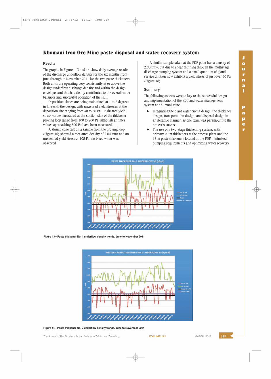
The graphs in Figures 13 and 14 show daily average resultsof the discharge underflow density for the six months fromJune through to November 2011 for the two paste thickeners.Both units are operating very consistently at or above thedesign underflow discharge density and within the designenvelope, and this has clearly contributes to the overall waterbalances and successful operation of the PDF.
Deposition slopes are being maintained at 1 to 2 degreesin line with the design, with measured yield stresses at thedeposition site ranging from 30 to 50 Pa. Unsheared yieldstress values measured at the suction side of the thickenerproving loop range from 100 to 200 Pa, although at timesvalues approaching 300 Pa have been measured.
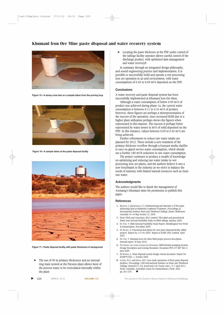
A slumlp cone test on a sample from the proving loop(Figure 15) showed a measured density of 2.04 t/m3 and anunsheared yield stress of 105 Pa, no bleed water wasobserved.
A similar sample taken at the PDF point has a density of2.00 t/m3, but due to shear thinning through the multistagedischarge pumping system and a small quantum of glandservice dilution now exhibits a yield stress of just over 30 Pa(Figure 16).
Summary
The following aspects were to key to the successful designand implementation of the PDF and water managementsystem at Khumani Mine:
� Integrating the plant water circuit design, the thickenerdesign, transportation design, and disposal design inan iterative manner, as one team was paramount to theproject’s success
� The use of a two-stage thickening system, withprimary 90 m thickeners at the process plant and the18 m paste thickeners located at the PDF minimizedpumping requirements and optimizing water recovery
Khumani Iron Ore Mine paste disposal and water recovery systemJournal
Paper
The Journal of The Southern African Institute of Mining and Metallurgy VOLUME 112 MARCH 2012 219 �
Figure 13—Paste thickener No. 1 underflow density trends, June to November 2011
Figure 14—Paste thickener No. 2 underflow density trends, June to November 2011
text:Template Journal 27/3/12 14:12 Page 219
� The use of 90 m primary thickeners and an internalring main system at the Parsons plant allows most ofthe process water to be recirculated internally withinthe plant
� Locating the paste thickener at the PDF under control ofthe tailings facility operator allows careful control of thedischarge product, with optimized dam managementand water recovery8.
In summary through an integrated design philosophy,and sound engineering practice and implementation, it ispossible to successfully build and operate a wet processingiron ore operation in an arid environment, with waterconsumptions of 0.43 to 0.69 m3/t deposited on the PDF.
Conclusions
A water recovery and paste disposal system has beensuccessfully implemented at Khumani Iron Ore Mine.
Although a water consumption of below 0.09 m3/t ofproduct was achieved during phase 1a, the current waterconsumption is between 0.11 to 0.16 m3/t of product.However, these figures are perhaps a misrepresentation ofthe success of the operation, since increased ROM due to ahigher plant utilization perhaps skews the figures whenrepresented in this manner. The success is perhaps betterrepresented by water losses in m3/t of solid deposited on thePDF. In this instance, values between 0.69 to 0.43 m3/t arebeing achieved.
Further refinements to reduce raw water intake areplanned for 2012. These include a new treatment of theprimary thickener overflow through a buoyant media clarifierto save on gland service water consumption, which shouldsee a further 180 m3/h reduction in raw water consumption.
The project continues to produce a wealth of knowledgeon optimizing and reducing raw water intake in wetprocessing iron ore plants, and the authors believe it sets anew benchmark in the industry as we strive to balance theneeds of industry with limited natural resources such as cleanraw water.
Acknowledgments
The authors would like to thank the management ofAssmang’s Khumani mine for permission to publish thispaper.
References1. HOUMAN, J. and JOHNSON, G. Commissioning and Operatio n of the paste
thickening farm at Kimberley Combined Treatment. Proceedings of International Seminar Paste and Thickened Tailings (Paste) MelbourneAustralia 14–16 May Section 12. 2003.
2. Paste Thick and Associates (Pty) Limited. Pilot plant and geotechnicalflume tests internal feasibility study on BKM tailings. January 2005.
3. DU TOIT, T. BKM Internal Feasibility Study Report: Metallurgical Test Work& Interpretation. November 2005.
4. DE SWART, G. Functional description for new paste disposal facility (BKMproject). Report No. 6 T-04 /2007. Report to ECMP (Pty) Limited. April2007.
5. DU TOIT, T. Khumani Iron Ore Mine BkM project process description. Internal report. 25 June 2010.
6. PATTERSON AND COOKE CONSULTING ENGINEERS. BKM Residue pumping System:Design Description and Costing Document. Document PST-677.R07 Rev 2.June 2005.
7. DE KONING, L. Paste disposal system design criteria document. Report No.ECMP!T1020- 1. October 2009.
8. COOPER, R.A. and SMITH, M.E. Case study operations of three paste disposalfacilities. Proceedings 14th International Seminar on Paste and ThickenedTailings (Paste2011), R.J. Jewell and A.B. Fourie (eds.), 5–7 April 2011,Perth, Australia, Australian Centre for Geomechanics, Perth. 2001. pp. 261–270. �
�
220 MARCH 2012 VOLUME 112 The Journal of The Southern African Institute of Mining and Metallurgy
Khumani Iron Ore Mine paste disposal and water recovery system
Figure 15—A slump cone test on a sample taken from the proving loop
Figure 17—Paste disposal facility with paste thickeners in background
Figure 16—A sample taken at the paste disposal facility
text:Template Journal 27/3/12 14:12 Page 220