scalable secure group communication over ip multicast 1 introduction
TRANSCRIPT

Scalable Secure Group Communication over IP MulticastSuman Banerjee, Bobby Bhattacharjee
Department of Computer Science, University of Maryland, College Park, MD 20742
Abstract
We introduce and analyze a scalable re-keying scheme for implementing secure group communicationsIP multicast. We show that our scheme incurs constant processing, message, and storage overhead for are-key operation when a single member joins or leaves the group, and logarithmic overhead for bulk simul-taneous changes to the group membership. These bounds hold even when group dynamics are not knowna-priori.
Our re-keying algorithm requires a particular clustering of the members of the secure multicast group.We describe a protocol to achieve such clustering and show that it is feasible to efficiently cluster membersover realistic Internet-like topologies. We evaluate the overhead of our own re-keying scheme and also ofpreviouslypublished schemes via simulationover an Internet topologymap containing over 280,000 routers.Through analysis and detailed simulations, we show that this re-keying scheme performs better than previ-ous schemes for a single change to group membership. Further, for bulk changes, our algorithm outperformsall previously known schemes by several orders of magnitude in terms of actual bandwidth usage, process-ing costs and storage requirements.
1 Introduction
IP multicast enables scalable wide-area multi-party applications over the Internet. In this paper, we describe anew algorithm for scalable, secure group communication over IP multicast. Our algorithm can be implementedover base IP multicast and does not require router support beyond best-effort forwarding. Since our scheme iscompletely end-host based, it can be used to implement group security over IP multicast-enabled untrusted,insecure networks.
1.1 Group Keys and Re-keying Groups
Many secure group communication systems [9, 1, 16, 6, 3, 12], including ours, rely on the notion of a “groupkey” — a secret known only to the members of the secure communication group1. Once a group key is dis-tributed to all current members of the multicast group, secure messages can be sent encrypted with the groupkey. The overall security of the group depends wholly on the secrecy and the strength of the group key. Sinceevery group member has the group key, sending a message involves only a single encryption at the sender anda single decryption at each receiver. The routers on the way treat each message no different than any other IPmulticast datagram. The only problem left to solve is to scalably and securely establish a group key known toall (and only) the members of the secure multicast group.
Since we assume the network infrastructure is insecure, it is possible for non-members to eavesdrop onthe multicast group and store encrypted messages (that they cannot decrypt). It is also possible for members
1It is possible to construct secure group communication systemswithout using a secret shared betweenall members. In such systems,trusted intermediaries, e.g. secure routers, must encrypt and decrypt messages en-route.
1

who have left the group to continue to decrypt messages and for new members to decrypt messages they hadstored previously. Therefore, during each membership change, a new group key must be distributed and allsubsequent communication must use this new key. This is the process of group re-keying: establishing a newgroup key upon a membership change in the secure multicast group. Note that depending on the requirementsof the application, it may or may not be necessary to re-key the group when a new member joins; but it is almostalways necessary to re-key the group when a member leaves.
Clearly, the overhead of the re-keying can be reduced (at the cost of reduced security) by batching the re-key operations, e.g. not re-keying every time there is a membership change but re-keying periodically or whena the group membership has changed sufficiently. Batching is important since re-keying operations affect everysingle member in the group, and can potentially be very expensive for large groups. Thus, re-keying schemesdesigned for large groups must be efficient when handling bulk simultaneous changes to the group membership.
The simplest solution for re-keying involves a pair-wise secure exchange of the group key between a centralkey server and each group member [9]. Unfortunately, this scheme incurs a O(N) overhead, where N is thenumber of group members, and is not viable for large groups. A particularly elegant protocol using hierarchi-cal “key graphs” was introduced in [16]. This is the first protocol that describes a scheme that incurs sub-linearoverhead for single membership changes to the group. In [6], a different scheme using boolean minimizationtechniques is described that is efficient for bulk membership changes. Both these schemes reduce the overheadfor the group re-keying operation for single membership change to O(logN). If more information is knownabout group dynamics, then it is possible to do better. MARKS [3] is a scheme that assumes that the durationover which a member stays attached to the group is known at the time the member joins. Using this informationa constant overhead solution is presented in [3]. In this paper, we present a constant processing, message, andstorage overhead solution for the general problem when the membership durations are not known; to the best ofour knowledge, ours is the first scheme with a provable constant bound. Further, we show that our scheme canhandle O(N) simultaneous changes to the group membership in O(logN) processing, and bandwidth com-plexity; this is a significant improvement on the previously knownO(N) bounds [6]. Obviously, the reductionof re-keying costs for single membership change fromO(logN) toO(1) is not very important unless the size ofthe group is very large. In simulations, our re-keying scheme performs better than previous schemes for singlegroup changes. However, for bulk group changes, our algorithm outperforms all previously known schemes byorders of magnitude in terms of actual bandwidth usage, processing costs and storage requirements.
1.2 Overview of Our Approach
Our scheme is based on a particular sized bounded, non-overlapping, clustering of multicast group members,which we call “spatial clustering”. Spatial clustering assures that members in the same cluster are near eachother in the multicast tree. The constant overhead re-keying scheme is implemented using a hierarchy of spatialclusters. Our re-keying scheme has low communication overhead precisely because it is based upon a spatialpartitioning of the multicast group which allows the key distribution scheme to exploit the parallelism inherentin different parts of a multicast tree.
This paper has two main contributions:
2

� We describe the an efficient re-keying algorithm for implementing group security over IP multicast. Ouranalysis shows that this scheme has constant overhead for a single group re-key even when the groupdynamics are not known a-priori. Further, we show that the overhead for bulk simultaneous changes islogarithmic in the number of group members. Both these results improve on previously known bounds.� We present detailed simulation of our own scheme, and also of previously published schemes includ-ing [16, 6]. Compared to previously published order analysis, our simulation results better measure theper router packet and bandwidthoverheads inherent in implementing secure group communication schemesover IP multicast.
We also describe an algorithm based on IP multicast for creating bounded-size non-overlapping clusters.Such clustering is potentially useful beyond secure multicast; however, we do not explore this topic further inthis paper.
1.3 Roadmap
In the next section, we describe existing approaches for key distribution for secure multicast. In Section 3,we describe our multicast key distribution scheme. In Section 4, we describe the underlying clustering algo-rithm required to implement our re-keying scheme. In Section 5, we present simulation results comparing ourscheme versus existing approaches and conclude in Section 6. We present a formal protocol specification andasymptotic complexity analysis for the re-keying algorithm in an Appendix.
2 Existing Approaches for Secure Multicast
Group Key Management Protocol (GKMP) [9] is a simple group management protocol in which a Group KeyController is responsible for generating group keys. In GKMP, static keys —pairwise shared between the GroupKey Controller and each group member— are used to establish a group key. The Scalable Multicast Key Dis-tribution (SMKD) [1] works in conjunction with the Core Based Tree (CBT) [2] multicast protocol to securelydistribute the multicast group key. The CBT root router initially operates as the entity responsible for genera-tion and distribution of the group key. This responsibility is delegated to other routers as they join the deliverytree. SMKD requires explicit router support, and does not scalably solve the problem of group re-keying.
In Iolus [12], the scalability of re-keying is handled by dividing the secure multicast group into multiplesub-groups. Security in each sub-group is managed by a Group Security Agent (GSA). The GSAs (and byconsequence, the sub-groups) are statically configured and located in different parts of the Internet. Each sub-group has its own sub-group key that is managed by the relevant GSA. Membership changes in any sub-grouprequire local re-keying of the sub-group key. If a global shared group key is used for the data, this key needs to bedistributed to members in each sub-group by sub-group specific means. Alternatively, if no global group key isused, changes in one sub-group do not affect the others, but expensive data-path encryptions and decryptions arenecessary. Since Iolus does not define sizes of subgroups etc., it is difficult to provide analytic bounds on Iolus’
3

performance (and hence it is not included in the simulation results). It is, however, possible to use an Iolus-likeinfrastructure to implement our scheme, and we discuss the details of such an implementation in Section 4.3.
As mentioned in Section 1, the MARKS [3] scheme defines a constant overhead key distribution protocol.More precisely, members in MARKS incur a one time cost which depends on the length of the time they stayin the group. MARKS is based upon the premise that many applications, e.g. pre-paid or subscription pay-TVor pay-per-view, do not (or rarely) require premature eviction. Thus, the protocol assumes that the durationover which a member stays in the group is known when the member joins. For single changes to the group, ourscheme provides better performance bounds without the known a-priori membership duration requirement.
The two protocols that are of most interest to us are the Key Graphs scheme by Wong, Gouda, and Lam [16],and the Boolean Minimization scheme by Chang, Engel, Kandlur, Pendarakis, and Saha [6]. Both these proto-cols and our protocol solve the re-keying problem under the same assumptions (unlike MARKS), and we out-line their operation in the next section. We are aware of two extensions to the Key Graphs scheme: the schemein [5] uses input doubling functions to reduce number of re-keying messages in half, and the scheme in [11]describe how to effectively re-key during bulk membership changes. In our simulations, we have implementedthe protocols described in [11].
2.1 Key Graphs and Boolean Minimization
u2 u4 u5 u6 u7u1 u3u0
k[0−7] changes to k[0−3,5−7]
k[4−7] changes to k[5−7]
k[45]
k0 k1 k2 k3 k4 k5 k6 k7
k[01] k[23] k[67]
k[0−3]
Figure 1: Key Graphs Scheme
k0 k0 k0 k0
k1 k1
u2 u4 u5 u6 u7u1 u3
k0 k0 k0 k0
k1 k1
k2 k2
u0
000 001 010 011 100 101 110 111
SK
Figure 2: Boolean Minimization Scheme
The first secure multicast protocol that did not incur linear re-keying cost for single membership change, wasproposed by Wong et al [16]. They define a tree hierarchy of keys distributed between different sets of members,as shown in Figure 1. The leaf nodes on the tree represent the different members, while the circular nodesrepresent the different keys. Each member ui possesses all the keys on its path to the root (from ki ! k[0 �7] in Figure 1). The root key serves as the group key. A central key server is responsible for generating anddistributing new keys as required. When a member (e.g. u4 in the figure) leaves the group, all keys on thepath from this member to the root needs to be changed. However, the updated keys can be multicast by the keyserver to the sub-groups instead of being unicast to individual members separately, and thus the re-keying costis O(logN). In [16] different re-keying —key-, user-, and group-oriented— schemes are described, each with
4

different processing, and message overheads. We have implemented all of these schemes in our simulation,and in our comparisons, we use the re-keying scheme that is most favorable to the Key Graphs scheme for theparticular experiment.
The boolean minimization technique [6] is another scheme that uses virtual key hierarchy-based scheme.There are 2 logN auxiliary keys, namely fk0; k1; : : :g and fk0; k1; : : :g 2 and one group keySK. If bR : : : b1; b0denotes the identifier of a member in binary notation, then that member has key SK and the auxiliary keysgiven by the following rule: For each i, if bi = 0, then the member has key ki, else it has key ki. This set ofauxiliary keys held by each member can be represented using a binary key tree as shown in Figure 2. When amember leaves the group, all group key along with the auxiliary keys held by the member need to be changed.A new group key is generated by a group controller and is encrypted with the keys that are complementary tothe keys held by the departing member. In the example in Figure 2, member u4 leaves: the new group key SK 0are therefore encrypted as fSK 0gk2 ; fSK 0gk1 ; fSK 0gk0 and distributed to the entire group. All and only theremaining members are able to decrypt the new group key. Further, a one-way hash function on the new groupkey is used to update the auxiliary keys known to u4. Using boolean minimization techniques to determinehow the group key is encrypted for distribution, this scheme is able to handle bulk membership changes morescalably than Key Graphs.
3 Secure Multicast using Clustering
In this section, we present our secure key distribution algorithm. We assume a member clustering protocol thatmaps multicast group members to clusters with the following properties:
Each cluster has between k and 2k � 1 members, for some fixed k, and consist of connected setsof tree members. Cluster topologies are non-overlapping, and no two clusters share a member.
The actual clustering protocol we describe in Section 4 does not ensure zero overlap, but instead guaranteesthat two clusters share no more than one member. This is an artifact of pathological configurations of multicasttrees for which it is not possible to maintain the both the size bound and the zero overlap condition. Even thisweaker condition, however, is enough to guarantee the clustering properties as required in our analysis of there-keying algorithm. (We do require that the maximum degree of the multicast delivery tree be independent ofthe group size).
3.1 Member Hierarchy for Key Distribution
Our key distribution scheme creates a member hierarchy as shown in the leftmost panel of Figure 3. A “layer”comprises of a set of members of the secure multicast group in the same level of the hierarchy. Layers arenumbered sequentially with the lowest layer of the hierarchy being layer zero (denote by L0). An instance ofthe clustering protocol is executed at each layer of the hierarchy to create a set of clusters, and all membersof the secure multicast group are part of the lowest layer (L0). The cluster leaders of all the clusters in layer
2Note that the keys kx and kx are not bitwise complements of each other, instead they represent two completely different keys.
5

A
B
F
G H
C
C E H
H
I A
B
F
G H
C
C E H
H
IEE
A
B D
F
G H
C
C E H
H
E
L1
L0 I
Only a single memberin this layer, cluster−leaderof layer L1
L0 form layer L1Cluster−leaders of layer
All members arejoined to layer L0
L2
J JJ
Key Server Key Server Key Server
[EJF key] [L0 key]
[L0 key] 210
Initial Arrangement of Members into Layers Member D leaves
Key server multicasts new L0 key to L1 membersE unicasts new cluster key J and F
Cluster leaders in L0 multicast new L0 key into respective clusters
Figure 3: Key distribution on a three layer hierarchy of members on the multicast delivery tree.Li join layer Li+1. For example, consider the arrangement of members in the initial configuration (Panel 0)of Figure 3. All ten members A–J are part of layer L0. The clustering protocol has partitioned L0 into threeclusters: [ABC], [DEFJ], and [GHI]3. The cluster leaders, C, E and H join layer L1. Another instance of theclustering protocol executes at layerL1 to create the single cluster [CEH]. The leader,H , of the layerL1 clusterjoins layerL2 — the highest layer in this example. The procedure terminates when there is only a single memberin any layer.
When a new member joins any layer, the clustering protocol places it into one of the clusters in that layer.Occasionally, arrival of a new member or the departure of an existing member from a layer can split or mergeclusters. This decision is part of the clustering protocol.
3.2 Layer Keys, Cluster Keys, Key Servers and Group Communication
A secret layer key is associated with each layer of the hierarchy. A group member possesses a layer key fora specific layer if and only if it is a member of a cluster in that layer. Layer keys are generated, on-demand,by a key server whenever a new member joins or an existing member leaves any layer. A secret cluster key isassociated with each cluster. Once again, a group member possesses a cluster key for a specific cluster if andonly if it is a member of that cluster. The leader of each cluster is responsible for generating the cluster keyfor that cluster. Finally, in all clusters, a pair-wise key is shared between the cluster-leader and each clustermember. Since all members belong to L0, the key for L0 is used as a shared key for secure communication.
3.3 Key Distribution Protocol
The key distribution protocol ensures that the layer key of each layer is only available to members joined tothat layer. Therefore, whenever a member leaves (or joins) a layer, a new layer key is required for that layer.This ensures that the layer key of layer L0 (which is the group key for the entire secure multicast group) isavailable only to members of L0, i.e. all and only the current members of the multicast group. In the rest ofthis section, we use three examples to illustrate how our protocol efficiently changes layer keys and maintainssecurity guarantees. In the examples, we assume that the cluster sizes must be bounded between 3 and 5. Aformal specification for the protocol is given in the Appendix.
3In referring to clusters in Figures 3 and 4 , we use the notation [XY...Z] to refer to a cluster with members X;Y , ..., Z .
6

A
B
F
G H
C
C H
H
I
D
D
A
B
F
G H
C
C H
H
I
D
DL0
L1
L2
A
B G H
C
C H
I
H
D
L2
L1
L0
A
B
F
G H
C
C H
I
D
D
H
A
B G H
C
C H
I
H
A
B G H
C
C H
H
ID
J
Key Server Key Server
Key Server
J
Key Server
Key Server Key Server
[DJF key]
J
[L0 key]
[CDH key]
[L0 key]3 5
J
[ABCDJ key]
[CH key]6
D drops out of L1. Two clusters merge in layer L0 Member F leaves from the configuration in 3.
New cluster keys are generated for L0 cluster ABCDJ and the L1 cluster CH, by cluster leaders C and H.
Member E leaves from initial configuration It was part of layers L0 and L1 D replaces E as cluster−leader in the L0 cluster (DJF) D unicasts new cluster key in DJF cluster D joins layer L1, and the cluster CDH H unicasts new cluster key in CDH cluster
[L1 key]
[L1 key]
4
Key server multicast the new L1 key to L2 members L2 members (cluster−leaders of L1) multicasts this new L1 key into respective L1 clusters
D
J
[L1 key]
7[L1 key]
As before, the new L1 key is generated, since the membership of L1 has changed (D is no longer member of L1, as it is not a cluster−leader in L0)
They are distributed as before into L0 clusters. new L1 key. members as before. It is encrypted using the New L0 key is multicast by key server to L1
J
[L0 key]
[L0 key]
8
Finally, new L0 key is generated and distributed as before.
Figure 4: Examples illustrating the key distribution scheme.
Example I: Member departure In Figure 3, we first consider the case that member D leaves the securemulticast group. Since D belongs only to L0, only the L0 layer key needs to be changed. The following arethe re-keying operations required :
1. A new L0 layer key request is made by E, the cluster leader of [DEFJ]4.Simultaneously,E sets up a newcluster key by pair-wise communication with each of the remaining members of this cluster (in this caseF and J), as shown in Panel 1.
2. The key server generates the new L0 layer key, and multicasts the new L0 layer key to all members inthe immediate higher layer, i.e. L1, encrypted by the current L1 layer key (Panel 1). (Recall that themembers of layer L1 are the cluster leaders of the clusters in layer L0.)
3. On receiving the new L0 layer key, the members of layer L1 (i.e. C, E and H) extract the new layerL0 key, and multicast it to the other members of their clusters in layer L0, encrypted by the respectivecurrent cluster keys. Note that when member E transmits the new L0 layer key in its L0 cluster (nowcomprising of E, F and J), it uses the new cluster key that it had set up thus ensuring D cannot decryptthe new layer key. The non-overlapping nature of the clusters ensure that the cluster multicasts occur inparallel and traverse disjoint parts of the delivery tree.
4If E leaves the group at the same time as D, then E’s departure would causeH , the cluster leader of cluster [CEH] in layerL1 , toinitiate new layer key requests for both layers L0 and L1.
7

Member Join A joining member is assigned to a L0 cluster by the clustering protocol at layerL0. The clusterleader in this cluster generates and distributes a new cluster key. Finally, the new L0 layer key is distributed,as explained steps 2 and 3 in the previous example.
Example II: Cluster Leader Departure In our next example, we refer to Figure 4, and consider the casewhen E, a cluster leader in layer L0 and a member of bothL0 and L1, leaves the original multicast group. There-keying operations proceeds as follows :
1. Some member, D, in this example, is chosen as the new cluster leader of the L0 cluster ([DFJ]). Sinceit is a leader in L0, D joins layer L1. The two affected clusters [DFJ] in layer L0 and [CDH] in layerL1 require new cluster keys. As shown in Panel 3, these keys are established by the cluster leaders bypair-wise unicast communication, using the respective pair-wise keys.
2. New layer keys, for both layersL0 andL1, are requested by the cluster leader (H) of the highest affectedcluster ([CDH]). The new L1 key is unicast to other members of [CDH] by H , since it is the leader ofan affected cluster. The new L0 key is multicast to layer L1 encrypted using the new L1 key. It is thenmulticast, using corresponding cluster keys, onto clusters [ABC], [GHI], and [DJF] by C, H , and D,respectively
It should be clear that whenever there is a change in membership in any specific layer Lj for j > 0, there is acorresponding change in all lower layers Li, 0 � i < j. Thus, in this example, H , which is the leader of theaffected cluster in the highest layer, immediately requests a new layer key for L1 and all lower layers.
Example III: Cluster Reconfiguration As a final example, we consider the case, when member F leaves thegroup from the configuration in Figure 4, Panel 3 (member E has already left). In this case, theDFJ cluster inlayer L0 shrinks to two members (D and J), violating size lower bound of 3. As a consequence, the clusteringprotocol merges the clusters DJ and ABC to create a cluster within the required size bound. Since, D is nolonger a leader of a L0 cluster, it must be removed from layer L1. Both layers L0 and L1 are rekeyed as in theprevious example.
3.4 Complexity Analysis
Along with the formal protocol specification, we have presented the complexity proofs for our algorithm inthe Appendix. We show that the processing costs of our scheme for single membership change to the groupand the number of keys stored at each member is of constant order. Leveraging the non-overlapping propertyof the clusters, we show that the communication cost per link on the multicast delivery tree is also constantfor a single membership change. More importantly, when we batch process multiple leaves (or equivalently,there are multiple simulataneous leaves in the group), the processing cost at the key server and the messagingoverheads have logarithmic bounds, which is a significant improvement over previously known bounds. Wesummarize our results and previously known results in Table 1.
8

Scheme Storage Processing (single change) Processing (O(N) change) Net. Load (Bytes/router)Member Key Server Member Key Server Member Key Server Single change O(N) change
GKMP 2 N + 1 1 N O(1) O(N) O(N) O(N)Key Graphs logdN + 1 Nd=(d� 1) � 2 d(logdN � 1) O(logN) O(N) O(d logN) O(N)Bool. Min. log2N + 1 2 log2N + 1 1 log2N O(1) O(N) O(logN) O(N)
Spatial Clustering � 4 logkN � 2 � 2 O(1) O(logN) O(1) O(logN)Table 1: Average costs for different secure multicast key distribution schemes. ForO(N), i.e. bulk, changes tothe group membership the overhead costs are typically maximized when N=2 members simultaneously leavethe group.
S
A
D
B
C
E
S
A
D
B
C
E
A
D
B
E
S
1. Member C joins and finds B as parenton receiving a periodic message of B
2. Member E finds C as new parenton receiving a periodic message of C
0. Members periodically multicast TTL−scoped
Parent−child relationon the overlay tree
TTL−scoped message
heart−beat messages to parent and children
Figure 5: Member discovery protocol example
4 Spatial Clustering
In this section, we outline an algorithm to partition the members of a multicast group into fixed size, (mostly)non-overlapping clusters, as required by the re-keying algorithm. The input to the clustering algorithm is amember overlay tree which contains only the multicast group members as nodes. As members join the multicastgroup, we use a member discovery protocol to establish a parent for each new member in the member overlaytree. We describe the member discovery protocol next and the clustering protocol in Section 4.2.
4.1 Member Discovery Protocol
The member discovery protocol takes a multicast topology as input, and outputs a member overlay tree. Themember discovery protocol defines parent-child relationships among the different members of the multicasttree. This is the only component that is inherently tied to the network layer multicast scheme being used. Net-work layer multicast schemes create data delivery trees, which are broadly classified to be either source-based(DVMRP [15]) or shared (CBT [2]) trees, each of which can be unidirectional (PIM-SM [7]) or bi-directional(CBT). We have defined different member discovery protocols tailored for each of these different network layermulticast schemes. In this paper, we focus on a network layer multicast scheme that creates shared bi-directionaltrees (e.g. Core Based Tree protocol [2]) and only describe the appropriate member discovery protocol. This
9

member discovery protocol uses mechanisms similar to the low overhead technique of fault isolation in multi-cast trees [13]. Let d(u; v) denote the distance, in router hops, between the members x and y along the multicastdelivery with source S. A member y is considered to be a parent of member x, if and only if the following twoconditions hold:
C1: d(S; y)� d(S; x). This condition ensures that the parent is closer to the source than the child.
C2: 8 z that satisfy C1, d(y; x)� d(z; x). This condition chooses the closest member that satisfies conditionC1.5
The protocol uses two periodic messages: the root S periodically multicasts a heartbeat packet to all themembers of the group, from which each member infers their distance to S. Periodically each member, x, mul-ticasts a TTL-scoped heartbeat message to parent and all of its children on the overlay tree. This message carriesthe tuple hd(S; x); P (x)i, where P (x) denotes x’s parent in the overlay tree.
We explain the tree construction using an example: Consider the network in Figure 5. In Panel 0, E sendsout a message with TTL five to reach its parent B. Assume a new member C joins the multicast group (asshown in Panel 1). Since C is part of the multicast group, the TTL-scoped message from B reaches C. Node Cis able to infer the multicast distance between B and C and hence, using the two specified rules, concludes thatB is its parent. If, however, the original messages from B does not reach C, then after a timeout, C initiates anExpanding Ring Search to locate a parent. Upon receiving a query from C, B updates its TTL-scope value suchthat its next heartbeat reaches C.
Finally, when C sends its periodic heartbeat scoped to reach B (Panel 2), it also reaches E. From conditionC1, E realizes that C is its new parent on the overlay tree and adjust its TTL-scoping accordingly. B stops gettingheartbeats from E and concludes that E is no longer its child. Note that even if the TTL-scoped message fromC did not reach E, the heartbeat message from E, scoped to reach its current parent B, is guaranteed to reach C.C would realize that it is a better candidate to be E’s parent and would adjust the TTL-scope of its heartbeat toreach E.
4.2 Clustering Protocol
The clustering protocol takes an integer k and a member overlay tree as input, and outputs clusters which are(mostly) non-overlapping, connected subsets of the tree, each between size k and 2k. To create the clusters,the tree is logically traversed from the leaves, upwards to the root. In this traversal, whenever a set of membersthat fall within the size bounds is detected, they are grouped into a cluster. These members are consideredpruned from the overlay tree for the remaining traversal. When this procedure terminates, it is possible that asingle cluster, located at the root of the overlay tree, may have size less than k. Additionally, this protocol alsoguarantees that two clusters share no more than one member.
5For a set of members that are equidistant from the source and each other, multiple members may satisfy both the conditions. Insuch cases, we use a simple lexicographic symmetry breaking technique to prevent loops.
10

���������������
���������������
A, and B are stable clusterswith sizes between k and 2k
C
u
v
Towards rootof overlay tree
C is unstable
B
A
3k/2
3k/43k/2
Figure 6: Stable clusters and unstable subtrees.
Procedure : MERGESUBTREES(u;STRootList; k)TempClusters ?; ThisCluster ?for v 2 STRootListThisCluster ThisCluster [ T (v)
if jThisClusterj � k � 1Add fug to ThisClusterAdd fThisClusterg to TempClustersThisCluster ?
if ThisCluster 6= ?�u ThisClusterreturn TempClusters
Figure 7: Procedure MERGESUBTREES.
Procedure: PROCESSCHILDMESSAGE(u;v; j�vjnew)Cu ?; �v j�vjnew � j�vjoldif v already belongs to some cluster C rooted at u
Update cluster size of C to be jCj+�vif jCj < k or jCj � 2k f C is disbanded gCu fwjw 2 Children(u) ^ w 2 (C [ �u)g
else f v was not part of any cluster rootedat u before, but may have been part of �u before gf Add �v to the unstable subtree, �u at u g
Update size of �u to be j�uj+�vif j�uj � kCu fwjw 2 Children(u) ^ w 2 �ugelse
Merge �u with an existing cluster if possibleif Cu 6= ?
New Clusters rooted at v MERGESUBTREES(u;Cu; k)
Figure 8: Procedure PROCESSCHILDMESSAGE. Cu isa list of u’s children s.t. the unstable subtrees rooted atthese children need to be merged to create new clustersat u. �v is the change in the subtree size between theprevious message from child v and this message.
4.2.1 Protocol Description
We refer to clusters of size between k and 2k as stable clusters. Clusters of size less than k or greater than 2kmay occur before the protocol stabilizes: we call these unstable clusters. In figure 6,A and B are stable clustersrooted at v.
Let �v denote the subtree, rooted at some node v which cannot be joined to any cluster rooted at v (doingso would render these clusters unstable). This subtree, which we call the unstable subtree, has to be joined to acluster that is rooted at a node upstream of node v. In Figure 6, �v = C. When the protocol stabilizes, C wouldbe part of a cluster rooted at a node upstream of v or be part of the single unstable cluster rooted at the root ofthe overlay tree.
Protocol Operation The clustering protocol proceeds as follows:� Initially when a member u joins the multicast group, it creates an unstable cluster, comprising only ofitself. This cluster is also an unstable subtree, i.e. �u = fug.� Each member u periodically sends a message to its parent containing the value j�uj.� The periodic message from child v to parent u is either a notification of a new unstable subtree rooted atv or of an existing unstable subtree rooted at v.
11

v |τ| = 0
u |τ| = k/2 u |τ| = k/2u |τ| = 0u |τ| = 0
wτ| | = 0wτ| | = 3k/4 + 1
v |τ| = 3k/4 v |τ| = 3k/4v |τ| = 3k/4���
���������
������������
����������������
����������������
7k/4
A
v
3k/4
A
B
v
u
3k/4
A
3k/4
A
B
w
v v
k/2 k/2 k/2 k/2
k/2
C
u
A and B now part ofsame stable cluster.
2. New member w joins 3. New subtree C appearsand is rooted at w. A and Care part of one stable clusterrooted at w. B is part of a
1. A shrinks to 3k/4.
0. Initially A is astable cluster rootedat v. B is part of acluster rooted upstreamof u.
separate cluster rooted upstreamof u.
and is located by memberdiscovery protocolbetween u and v.
the same stable cluster.All members are part of
B B
Figure 9: Clustering protocol example
If �v is an previously known subtree, then it part of some existing cluster (or the unstable subtree) rootedat u. In this case, u checks to see if the size of �v has changed. If the size has changed sufficiently, u mayhave to split or merge a cluster that �v is part of. If �v is part of the unstable subtree, u may now be ableto create a new stable cluster.
If the message is for previously unknown subtree, this new subtree is added to the unstable subtree rootedat u. Node u tries to merge the its new upstream cluster with its existing clusters. This procedure maycause a new stable cluster, rooted at u to be formed. All subtrees that cannot be put into any cluster formthe new unstable subtree rooted at u.
We list the exact procedure for handling child messages in Figure 8.
Example We illustrate the operation of the clustering protocol with the example shown in Figure 9.� Initially, the overlay tree has a clusterA rooted at the member v. Member v has no unstable subtree, andsends j�vj = 0 to its parent u. Member u has an unstable subtree, B, which is part of a cluster rootedupstream from u.� At a later time (Panel 1), the clusterA reduces below size k, making it unstable and is advertised by v asan unstable subtree. As a consequence, at u, j�uj = 3k=4+k=2 � k. The procedure MERGESUBTREES
is called on the two subtrees A and B to create one single cluster. No unstable cluster is created rootedat u. So �u becomes empty.� Next (as shown in Panel 2), a new member w joins the overlay tree. The member discovery protocollocates it between u and v but there is no change in the clusters.
12
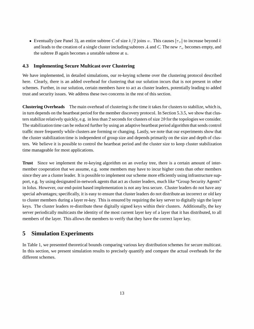
� Eventually (see Panel 3), an entire subtree C of size k=2 joins w. This causes j�wj to increase beyond kand leads to the creation of a single cluster including subtrees A and C. The new �w becomes empty, andthe subtree B again becomes a unstable subtree at u.
4.3 Implementing Secure Multicast over Clustering
We have implemented, in detailed simulations, our re-keying scheme over the clustering protocol describedhere. Clearly, there is an added overhead for clustering that our solution incurs that is not present in otherschemes. Further, in our solution, certain members have to act as cluster leaders, potentially leading to addedtrust and security issues. We address these two concerns in the rest of this section.
Clustering Overheads The main overhead of clustering is the time it takes for clusters to stabilize, which is,in turn depends on the heartbeat period for the member discovery protocol. In Section 5.3.5, we show that clus-ters stabilize relatively quickly, e.g. in less than 2 seconds for clusters of size 20 for the topologies we consider.The stabilization time can be reduced further by using an adaptive heartbeat period algorithm that sends controltraffic more frequently while clusters are forming or changing. Lastly, we note that our experiments show thatthe cluster stabilization time is independent of group size and depends primarily on the size and depth of clus-ters. We believe it is possible to control the heartbeat period and the cluster size to keep cluster stabilizationtime manageable for most applications.
Trust Since we implement the re-keying algorithm on an overlay tree, there is a certain amount of inter-member cooperation that we assume, e.g. some members may have to incur higher costs than other memberssince they are a cluster leader. It is possible to implement our scheme more efficiently using infrastructure sup-port, e.g. by using designated in-network agents that act as cluster leaders, much like “Group Security Agents”in Iolus. However, our end-point based implementation is not any less secure. Cluster leaders do not have anyspecial advantages; specifically, it is easy to ensure that cluster leaders do not distribute an incorrect or old keyto cluster members during a layer re-key. This is ensured by requiring the key server to digitally sign the layerkeys. The cluster leaders re-distribute these digitally signed keys within their clusters. Additionally, the keyserver periodically multicasts the identity of the most current layer key of a layer that it has distributed, to allmembers of the layer. This allows the members to verify that they have the correct layer key.
5 Simulation Experiments
In Table 1, we presented theoretical bounds comparing various key distribution schemes for secure multicast.In this section, we present simulation results to precisely quantify and compare the actual overheads for thedifferent schemes.
13

5.1 Experimental Setup
We begin with a description of the topology we used to conduct our experiments, and describe the implemen-tation of the various schemes.
Network Topology and Multicast Support We experimented the key distribution performance of the differ-ent schemes on a large Internet map obtained by the SCAN project6. This map, created using the Mercator [8]tool, contains about 280; 000 IP routers discovered using traces on the Internet. About 50% of all the routersin the map were edge routers, to which we attached between 10; 000 and 500; 000 hosts routers uniformly atrandom for different experiments.
We have simulated network infrastructures that do and do not support directed multicast. Directed multicastallows a sender multicast a packet to individual subtree(s) rooted at a specific router on the multicast deliverytree. This is not currently a part of the IP multicast standard, but is extremely useful for many network services,e.g. NAK suppression for reliable multicast. It has been proposed in research, e.g. AIM [10], and is currentlybeing considered by the IETF as part of the PGM [14], and GRA [4] efforts. In our experiments, many re-keying schemes show marked performance improvements when implemented over a directed multicast capablenetwork.
In the absence of directed multicast, the same effect can the achieved by using a different multicast addressfor each subset of nodes that have to be addressed. For our scheme, which requires addressing clusters individ-ually, and for some key graph schemes, using a different address for each addressable subgroup is not viablesince the number of multicast addresses required would be on the order of the number of receivers. Instead, weuse TTL-scoping to limit packets to a certain part of the multicast tree. The network load for using such scopedmulticast is often significantly higher than pure directed multicast.
Scoped multicast using a single multicast address and directed multicast are two extremes in multicast ad-dressing capabilities. It is possible to approximate the effects of directed multicast by using multiple multicastaddresses, and using TTL-scoped multicast on each of these addresses. In our experiments, we consider di-rected multicast, scoped multicast with only one address, and scoped multicast with a small, fixed number ofaddresses.
5.1.1 Implementing Key Graphs and Boolean Minimization
We have implemented both the Key Graph and Boolean minimization schemes along with our own scheme.The key graphs scheme described in [16] proposes three different re-keying techniques: user-, key-, and group-oriented re-keying. The bandwidth requirements of the user- and key-oriented re-keying are of the same order;therefore, we present results from key-oriented and group-oriented re-keying only. When directed multicast isavailable, key-oriented re-keying has the lowest overhead, while group-oriented re-keying has lowest overheadwhen scoped multicast has to be used. In our simulations, we use key oriented re-keying for the directed mul-ticast scenario and the group oriented re-keying scheme for scoped multicast. For all implementations of thekey graphs scheme, we used 4-ary key tree graphs, as was proved to be optimal in [16].
6More detail about SCAN are available at http://www.isi.edu/scan
14

Along with the different re-keying strategies, we implemented two variants of the key graph algorithm,which we refer to in the results as KG-sequential and KG-spatial. These two schemes differ in the way theunique member identifier —which defines the position of a member in the key tree— is assigned to each groupmember. For both schemes, members join the multicast tree in a random sequence.
In the KG-sequential scheme, members are assigned sequentially increasing identifiers in the order theyjoin. In the KG-spatial scheme, members are not assigned identifiers according to their join sequence. Instead,we assign the identifiers in sequence via a post-order traversal of the multicast topology of all the members.The identifier assignment of the KG-spatial scheme ensures that members that share keys are close to eachother on the multicast tree. However, in order to ensure nearness on the tree, identifiers have to be reassignedas members join and leave the group: this process accrues a cost linear in the number of group members. In ourperformance comparison in Section 5.3, we ignore this cost. However, the performance of the KG-spatial vari-ant is significantly better than KG-sequential and any real implementation of Key Graphs on a large topologymust address the identifier assignment issue7. Lastly, as noted before, for bulk simultaneous to the key graph,we implemented the improved batch update algorithm described in [11].
For the boolean minimization scheme we implemented the key distribution scheme described in [6]. Weused the publicly available logic minimization tool, Espresso8 to determine the necessary boolean reductions.Since the key distribution technique in the boolean minimization scheme encrypts all the necessary keys to beupdated and multicasts them in a single message, we report the network load only for scoped multicast.
5.2 Experimental Methodology
For each experiment:� We generated a random set of group members attached to the leaf routers of the Mercator Internet map;� Next we create the multicast delivery tree, using the CBT protocol [2].� For our scheme, we compute the member overlay tree and execute the protocol described in Section 4 toidentify the clusters using cluster size between 8 and 15.� We implement the key distribution protocol for our scheme, Key Graphs, and the Boolean Minimizationon the same set of members� Next we choose, uniformly at random, a set of members to leave the multicast group simultaneously andrecord the storage, processing, message, and byte cost overheads at each node and each link of the tree.
In Section 5.3, we will present results as we vary two parameters: the group size and the number of membersthat simultaneously leave the group. For each parameter, we repeated each experiment 100 times, each with arandomly chosen set of departing receivers, and obtained 95% confidence intervals. In all cases, our confidenceintervals were extremely tight and we do not report them in the results.
7It should be noted that our assignments of identifiers to members does not optimally solve the assignment problem; unfortunately,we found that the problem is NP-complete for all key trees with tree degree greater than two.
8Espresso is publicly available at http://www-cad.eecs.berkeley.edu/Software/software.html
15

Single member leaves (varying group size) 1% of group leave (varying group size)Scheme 3000 6000 12000 24000 48000 96000 3000 6000 12000 24000 48000 96000
KG-sequential 4.9 5.6 5.0 6.0 5.3 6.3 23.2 32.8 36.3 49.5 57.1 76.8KG-spatial 1.9 2.1 1.6 2.0 1.5 1.8 10.3 13.7 14.9 18.7 20.8 27.0
Spatial clustering 1.6 1.6 1.7 1.7 1.7 1.8 3.2 3.3 3.4 3.4 3.5 3.6
Table 2: Comparison of key normalized byte count per router on a directed multicast-capable network.
Performance Metrics In our results in the next section, we report the following metrics:� Key-normalized byte count: This is the network overhead for re-keying at a single router assuming unit (1byte) key size. The actual byte overhead can be obtained by simply scaling the key-normalized byte countby the key size, and accounting for packet headers, etc. This metric is a measure of the total bandwidthrequirements of a scheme.� Packet load: This is a count of the number of packets processed by the routers on the multicast tree. Tocompute the packet load, we assume a key size of 512 bits, and the maximum IP packet size of 576 bytes.� Storage and Processing Overhead: These numbers refer to the number of keys stored at each node andthe number of cryptographic operations at each node. These numbers are independent of the particularsof the topology.
5.3 Simulation Results
We simulated the various key distribution schemes over multiple topologies and different network configura-tions. We begin with the results for the case when the underlying network is capable of directed multicast.
5.3.1 Directed multicast
In Table 2 we present the results for two different Key Graph implementations and compare them to our scheme.(Recall that since Boolean Minimization sends all messages to the entire multicast group, its performance isequivalent under directed and scoped multicast. We defer results for Boolean Minimization till the next sectionwhen we consider scoped multicast.) For each scheme, we have tabulated the average byte overhead at eachrouter (assuming one byte keys) when a single member leaves and when member leaves are batch processedafter 1% of the members leave the group. We analyze the actual number of bytes and IP packets in Section 5.3.4,and other batch sizes in Section 5.3.3.
It is clear from Table 2 that for a single leave, both the KG-spatial and our algorithm perform on par (andthat they both have lower costs than the KG-sequential scheme). However, as members leave simultaneously,or if number of member departures are processed in batch (e.g. shown by the 1%-leave results), our clustering-based scheme significantly outperforms both Key Graph implementations. Finally, we note that our KG-spatialvariant of the Key Graph scheme outperforms the originally published scheme by a factor of2:5�3. (Obviously,this is without accounting for the member–identifier assignment overhead of KG-spatial scheme.)
16

Single member leaves (varying group size) 1% of group leave (varying group size)Scheme 3000 6000 12000 24000 48000 96000 3000 6000 12000 24000 48000 96000
Key graphs 22.2 23.9 26.8 28.5 31.0 32.4 394.2 792.7 1578.2 3092.7 6222.7 12609.6Boolean minimization 11.0 12.3 13.5 14.2 15.0 16.2 53.5 94.8 169.9 302.6 567.3 1077.0
Spatial-1 162.5 125.7 121.1 117.5 130.0 117.7 296.4 221.4 190.8 191.2 198.1 208.1Spatial-16 8.7 11.0 13.9 16.5 19.3 20.6 10.3 12.8 16.2 19.1 22.4 24.1Spatial-24 6.3 8.1 10.5 12.1 14.4 15.3 8.2 10.3 12.5 14.7 17.1 18.5
Spatial-directed 1.6 1.6 1.7 1.7 1.7 1.8 3.2 3.3 3.4 3.4 3.5 3.6
Table 3: Comparison of normalized byte load per router for the different schemes using scoped multicast.
5.3.2 Scoped multicast
In Table 3 we compare the key-normalized byte load for different re-keying schemes using when TTL-scopedmulticast is the only primitive available from the network. Group-oriented re-keying for Key Graphs is opti-mally suited for scoped multicast, and the member assignment issue is not relevant (both KG-sequential andKG-spatial have identical performance).
We repeated the scoped multicast experiments with different number of multicast addresses for the spatialclustering scheme. In Table 3, Spatial-i indicates that i different multicast addresses have been used by thespatial clusters for intra-cluster communication. We use a simple decentralized address assignment scheme inwhich each cluster picks one multicast address (among the i available) at random, independent of each other 9.As is evident in Table 3, for a single leave, Spatial-1 (our scheme using only a single multicast address) performsfar worse than all other schemes. This is because even with TTL-scoping traffic local to a cluster “spills over”to a large part of the multicast tree. As more addresses are used, the TTL-scoping becomes more effective andthe spill over effect is effectively mitigated. For our scheme, the availability of directed multicast represents thebest possible scenario since it effectively provides logical addressing for individual clusters. We have includedthe costs under directed multicast as a lower bound.
There are two conclusions we can draw from Table 3:� Using a small number of multicast groups, our scheme can performs on par or better than existing schemesfor single member departures.� Our scheme has much lower overhead than all existing schemes for batched updates to the group, upto1 � 3 order of magnitude better when the group membership changes is of order N (shown by the 1%set of results in the table).
These conclusions lead to two questions:� How many departures have to be processed in bulk before we significantly outperform existingapproaches?It is clearly not always feasible or desirable to wait till O(N) members have left before the group is re-keyed.
9Given i addresses, the optimal assignment of addresses to clusters such that the extra traffic is minimized is also NP-complete.
17

10
100
1k
10k
1 4 16 64 256 1024 3k 6k 12k
Key
-nor
mal
ized
byt
e lo
ad
Number of hosts leaving the group simultaneously
Initial group size 24000
Key graphsBoolean minimizationSpatial-16Spatial-4Spatial-1
Figure 10: Varying the number of simultaneouslyleaving members (Scoped multicast)
0
0.2
0.4
0.6
0.8
1
1 5 10 15 20 25 30
Cum
ulat
ive
Fra
ctio
n of
Rou
ters
Number of clusters whose traffic passes through a router
Group size 24000, ~ 3100 clusters and ~ 17000 routers
4 m/c gps
16 m/c gps
64 m/c gps256 m/c gps
Directed m/c (Ideal)
Single m/c gp
32 m/c gps
Figure 11: Cumulative distribution of the routers thathandle cluster traffic for different number of clusters� How many multicast addresses do we need to get decent performance, especially for large group sizes?
We addresses these two questions, in turn, in the next two sections.
5.3.3 Impact of batched updates and multiple multicast addresses
Batched updates are likely to be used in most realistic scenarios, especially with large group sizes. In Figure 10we present results from an experiment in which we varied the number of members that simultaneously departthe multicast group. For each re-keying scheme, the figure plots the key normalized byte overhead for the entiregroup (added over all the tree routers) as different numbers of members simultaneously leave a 24,000 membersecure multicast group. The effectiveness of the O(logN) bulk update provided by our scheme is clear in theplot from the shape of the Spatial-x curves in the plot. In comparison, all existing schemes incurO(N) cost andperform worse than even Spatial-1 when more than 128 members are processed in bulk. Using 16 addresses isenough to ensure that our scheme outperforms existing schemes for all batched updates to the group and we are afactor of two better than the previously best known scheme if we batch only 16 departures for a 24,000 membergroup. Lastly, we note that our scheme performs a further order of magnitude better if directed multicast isavailable.
Using multiple multicast addresses It is clear from Table 3 that the performance of our scheme can be im-proved by using multiple multicast addresses. Unfortunately, it is difficult to optimally use a given set of ad-dresses, and was not apparent how many addresses should ideally be used for a given group size. Fortunately,directed multicast provides bounds the performance of the scoped multicast implementations: the extra over-head of the scoped multicast implementations is precisely the “spill-over” traffic because of ineffective TTL-scoping.
In order to quantify the gains from using multiple addresses, we varied the number of addresses used and
18

A single member leaves 1% of group leaves 10% of group leaves 25% of group leavesScheme KBytes Packets KBytes Packets KBytes Packets KBytes Packets
Key graphs 1.8 4 197.9 370 905.2 1689 1273.1 2376Boolean minimization 1.0 2 12.2 37 100.2 187 184.3 344
Spatial-1 7.5 118 12.2 191 12.8 200 12.3 193Spatial-16 1.0 17 1.2 19 1.5 23 1.5 23
Spatial-directed 0.1 2 0.2 4 0.5 8 0.5 8
Table 4: Comparison for key-normalized byte and packet loads per router (Group size: 24000 initial members).
randomly assigned clusters to available addresses. We then noted, for each router in the multicast tree, the num-ber of clusters for which the router carries any traffic. In the theoretically ideal case, for perfectly disjointedclusters, all routers should carry traffic from only a single cluster. (In comparison, in the very worst case, with-out TTL-scoping and if only a single address is available, all routers carry traffic from every cluster!). Ourresults are shown in Figure 11: for different number of multicast groups, we plot the cumulative distributionof the routers for different number of clusters whose traffic pass through the routers. We see that when a singlemulticast address is used, more than 70% of the routers carry traffic for at least 30 different clusters. The bestcase is observed for directed multicast, where 95% of the routers carry traffic for at most 2 clusters. Even withonly 32 addresses, the cluster overlap falls significantly (80% of the routers carry traffic 10 or less clusters). Weconclude that for groups with tens of thousands of members, few addresses (16� 32) approximate most of thebenefits of directed multicast, and are sufficient to better all existing schemes.
5.3.4 Packets, Processing and Storage
In this section, we quantify the costs of our scheme in terms of number of packets processed at the routers andthe processing and storage requirements at individual group members.
In Table 4, we present a comparison of both the byte and packet loads of the various re-keying scheme.For this experiment, we assumed the 576 bytes maximum IP packet sizes (536 bytes payload, and 512 bit keysizes). For a single member departure from a group of 24,000 initial members, the key server has to perform28 encryptions (4-ary key tree of height 8) for the key graphs scheme, which translates to a message of sizeabout 1:8 Kbytes (4 IP fragments). Similar computations show that 2 IP fragments are processed per router forthe boolean minimization scheme. In contrast, Spatial-1 requires more significant processing at each router,because of the high spill-over traffic. As expected, the number of packets can significantly be reduced by usinga small number of multicast addresses. Like in the normalized cost case, for batched updates to the group, ourscheme outperforms existing approaches with respect to the packet and byte count metrics. Depending on thelevel of batching and the number of addresses used, the gains from spatial clustering are quite dramatic, oftenusing orders of magnitude less packets than previously known results.
In Table 5, we show the key storage requirements and the processing cost at the key server and individualmembers for a group of 24,000 members. The processing cost is due to the crytographic operations when thegroup membership changes. While the number of keys at each member is low for all the schemes, the numberof keys stored at the server is significantly lower for both boolean minimization and spatial clustering scheme.
19

Number of Keys Processing at members Processing at key serverScheme Member Key server Single leave 1% leaves 10% leaves Single leave 1% leaves 10% leaves
Key graphs 9 32002 1.7 5.5 6.36 28.0 3095.3 14310.5Boolean minimization 15 31 1.0 1.0 1.0 15.0 302.9 1583.5
Spatial clustering 3 6 1.2 1.5 2.4 1.3 3.5 4.0
Table 5: Comparison of storage and processing costs for the different schemes for a group of 24,000 initialmembers
Cluster Total Num. Avg. Cl. Avg (Max)size bound of Clusters Size Stab. Time (s)
4 – 7 45 5.6 1.45 (2.63)10 – 19 17 14.7 1.85 (3.87)20 – 39 9 27.8 2.22 (4.60)
Table 6: Cluster characteristics
250 initial group membersNo. of Simultaneous Changes1 4 16 64 224
Join 1.0 1.8 2.4 3.6 4.3Leave 0.5 1.6 3.3 4.0 5.1
Table 7: Cluster stabilization time (in seconds)
Our scheme leads to lower processing at the key server for single leaves. For batch updates, the processingat the key server is bounded by O(logN) for our scheme, which is a substantial improvement over the O(N)costs for both Key Graph and Boolean Minimization schemes.
5.3.5 Experiments with the Clustering Protocol
We have also implemented a packet-level simulator of the spatial clustering scheme on the ns (version 2) sim-ulator to study the time dependent overheads of the protocol. We present only a synopsis of the main results.Due to high processing and memory demands of ns, we were limited to simulations on topologies of upto 1000routers. In Table 6, we present results from an experiment where a set of 250 members joined a single multicastgroup, all between simulation time 0 and 1 second. The member discovery and clustering protocols arrange themembers into size bounded clusters; in all our experiments, the size bounds were met by all the clusters. Thetime required (in seconds) for clustering is shown in the last column of Table 6. For these experiments, we usedfour heartbeats per second which resulted in about 40 bytes of traffic per second, scoped within the cluster. Weused only periodic heartbeats, and not the adaptive technique described in Section 4.3, which can further reducethe stabilization time.
Even though we only simulated on topologies on the order of 1000 nodes, we are confident that the stabiliza-tion times we present are representative of large topologies. This is because, in our experiments, we observedthat in the vast majority of cases, independent of group size, a single join or leave to the group affects less thantwo clusters. As multiple simultaneous changes occur, the clustering occurs in parallel over the entire topology;the total time taken for stabilization depends primarily on the cluster size and depth, and not on the size of thegroup.
20

6 Summary and Conclusions
In this paper, we have presented a new algorithm for efficiently implementing secure group communicationsover IP multicast. For all metrics, our scheme provides the best analytic bound, frequently improving on previ-ously known results. For single group changes, our improvements reduce previously known logarithmic boundsto constants, are probably only of theoretical interest. However, for bulk simultaneous group changes, our theo-retical results for network load and processing cost at the key server are significant, since they reduce previouslyknown linear bounds to logarithmic bounds.
Unlike existing approaches, our re-keying algorithm was designed to utilize the parallelism inherent in themulticast tree topology. Therefore, we expect our algorithms to perform extremely efficiently in practice. Asshown by our extensive simulations on a large realistic topology, for large groups, the number of messages andencryptions required by our scheme is often orders of magnitude lower than existing approaches, especiallywhen we consider simultaneous changes to the group. Our experiments also show that directed multicast is anuseful primitive for implementing many secure multicast schemes, including ours.
Due to the extra overhead of implementing and executing a clustering protocol, it is unlikely that our schemewill be useful for small groups. However, we have shown that the time and network overhead for the clusteringis relatively small, and more importantly, controllable by varying simple parameters. Further, the clusteringoverhead is independent of the group size, and depends only on cluster sizes.
References
[1] A. Ballardie. Scalable Multicast Key Distribution. Network Working Group, RFC 1949., May 1996.
[2] Tony Ballardie, Paul Francis, and Jon Crowcroft. Core based trees (CBT). Proceedings of SIGCOMM, September 1993.
[3] B. Briscoe. MARKS : Zero side effect multicast key management using arbitrarily revealed key sequences. In 1st InternationalWorkshop on Networked Group Communication, Pisa, Italy, November 1999., Pisa, Italy, November 1999.
[4] B. Cain, T. Speakman, and D. Towsley. Generic router assist (gra) building block motivation and architecture. Internet Draft,Internet Engineering Task Force, March 2000. Work in progress.
[5] Ran Canetti, Juan Garay, Gene Itkis, Daniele Micciancio, Moni Naor, and Benny Pinkas. Multicast security: A taxonomy andefficient constructions. In Proceedings of INFOCOM, New York, March 1999.
[6] I. Chang, R. Engel, D. Kandlur, D. Pendarakis, and D. Saha. Key management for secure internet multicast using boolean functionminimization techniques. In Proceddings of Infocom, New York, March 1999.
[7] D. Estrin, D. Farinacci, A. Helmy, D. Thaler, S. Deering, M. Handley, V. Jacobson, C. Liu, and P. Sharma. Protocol IndependentMulticast-Sparse Mode (PIM-SM): Protocol Specification. RFC 2362, 1998.
[8] R. Govindan and H. Tangmunarunkit. Heuristics for Internet Map Discovery. In Proceedings of Infocom, March 2000.
[9] H. Harney and C. Muckenhirn. Group Key Management Protocol (GKMP) Architecture. Request for Comments (Experimental)2094, Internet Engineering Task Force, July 1997.
[10] B.N. Levine and J.J. Garcia-Luna-Aceves. Improving Internet Multicast with Routing Labels. In Proc. IEEE International Con-ference on Network Protocols, pages 241–50, October 1997.
[11] X. Li, R. Yang, M. Gouda, and S. Lam. Batch updates for key trees. Technical report, University of Texas, Austin, September2000.
21

[12] S. Mittra. Iolus: A framework for scalable secure multicasting. Proceedings of SIGCOMM, October 1997.
[13] A. Reddy, R. Govindan, and D. Estrin. Fault isolation in multicast trees. Proceedings of SIGCOMM, August 2000.
[14] T. Speakmanet al. PGM reliable transport protocol. Internet Draft, Internet Engineering Task Force, April 2000. Work in progress.
[15] D. Waitzman, C. Partridge, and S. Deering. Distance vector multicast routing protocol. RFC 1075, 1998.
[16] C.K. Wong, M. Gouda, and S. Lam. Secure group communications using key graphs. Proceedings of SIGCOMM, September1998.
A Key Distribution Protocol
We assume a clustering protocol exists that creates and maintains clusters, as specified in Section 3. The clusters havesize between k and 2k � 1, for some fixed k, are non-overlapping and proximal subsets of the multicast delivery tree. Ahierarchy of members is created as shown in Figure 3 as follows:
All members are part of the lowest layer, L0. Each layer, Li, runs an instance of the clustering protocol tocreate a set of clusters, the leaders of which join the next higher layer, Li+1.
Each layer has a secret layer key known to only the members of the layer. Similarly, each cluster in each layer has a secretcluster key, known to only all the cluster members.
A.1 Notation� Members and Member Sets
– Cluster (u; j): Cluster of layer Lj , to which member u belongs.
– Leader (u; j) : Leader of the cluster in layer Lj to which member u belongs.
– S : The key server for all layer keys.� Keys and Messages
– �G(t): The secret key of G at time t, where where G is a set of members. If G is a cluster, then this is thecluster key, if G is a layer, then this is the layer key. If G is a pair of members, then this is a key shared onlyby these two members.
– fmge: Message m is encrypted by the key e.
– hUnicast :: u ! v : xi: u sends a unicast message x to v.
– hMulticast :: u ! G : xi: u multicasts message x to set of members G, where G is either a cluster or alayer.
A.2 Distributed Re-keying Operation
When a member u joins or leaves layer Lj , the following operations are performed distributedly by the key distributionprotocol:
1. Cluster re-key: Leader (u; j) generates a new cluster key �Cluster (u;j)(t + 1) and unicasts it to each currentmember of the cluster Cluster (u; j) encrypted separately by the pair-wise key of the leader with each member.8v 2 Cluster (u; j); hUnicast :: Leader (u; j) ! v : f�Cluster (u;j)(t+ 1)g�fLeader (u;j);vgi
22

Obviously, in case u is leaving this cluster, this message is not sent to u. The total communication overhead of thiscluster re-key is O(k) per link (due to O(k) pair-wise communication between the cluster-leader and the clustermembers).
2. Layer re-key: The key server,S, generates a new layer key for layer Lj , and multicasts it to all members of layerLj+1 — these are the cluster-leaders of the clusters of layer Lj . Each cluster leader of layer Lj then performs acluster multicast to all the members of its cluster in layer Lj . The multicast messages are encrypted by the appro-priate keys. hMulticast :: S ! Lj+1 : f�Lj (t+ 1)g�Lj+1(t)i8v 2 Lj+1; hMulticast :: v ! Cluster (v; j) : f�Lj (t+ 1)g�Cluster (v;j)(t+1)iThe multicast message from S to layer Lj+1 traverses each link only once. The cluster multicasts of the cluster-leaders of layer Lj traverse spatially disjoint parts of the multicast delivery tree. Hence, only one cluster multicastmessage traverses each link in the tree. Thus, the combined communication cost of these multicasts is O(1) perlink.
The total communication cost for distributed re-key operation in each layer is, therefore, O(k) per link.
A.3 Re-keying algorithm for member joins and leaves
When a new member joins the secure multicast group, it is inducted into some L0 cluster. When a member leaves thegroup, it leaves from all the layers it was joined to. In both cases, the clustering protocol appropriately re-clusters theseaffected layers. Upon a membership change, the re-keying algorithm re-keys each affected cluster and each affected layer,in turn using the cluster re-key and layer re-key primitives, respectively.
A.4 Analysis
We analyze three different metrics — key storage requirements at each member, the processing costs due to encryptionsand decryptions at each member and the communication overheads per link of the multicast delivery tree for each re-key.
Assume that there are N members currently joined to the secure multicast group. Let LR be the highest layer in thehierarchy (it contains a single member). The following properties hold :� R � logk N . For all j in [0; R], layer Lj has not more than N=(kj) members.� If a member u, is present in Lj , it is present in all lower layers L0 : : :Lj�1. If a member u is not present in layerLj, it is not present in any of the higher layers, Lj+1 : : :LR.
Communication Cost Most members (i.e. at least N (1� 1k ) of them) are joined only to the lowest layer, L0. Hence,a majority of member joins and leaves affect only layer L0 and the communication cost incurred for the necessary re-keying is O(k), a constant (as shown before). In the worst case, the single member at the highest layer LR leaves, all thelayer keys would need to be changed. Each layer key change requires O(k) communication cost per link, which makesthe worst case communication cost of O(k logkN ) for leaves (and analogously for joins).
Under the assumption that each member of the group is equally likely to leave (and join), we now show that theamortized cost for joins and leaves is constant. We consider the case of a member leaving the group. Consider the casewhen a member u, joined only to layers Lj : : :L0, leaves the secure multicast group. Each of these j + 1 layer keysneed to be changed. The communication cost per link for each layer key change is O(k). Additionally, in each layer, itcan be shown that at most two clusters would need to be re-clustered (if size of the affected cluster falls below the size
23

lower bound, k). Due to the clustering protocol, this would involve communication cost ofO(k) per link. Hence, the totalcommunication cost per link due to re-keying of all the layers, for member u leaving the group is O(k(j + c)), where cis some constant. For any layer, the number of members in layer Lj is bounded by N=kj. Thus, the amortized cost of fora member leaving the multicast group is given by :1N RXj=0 jLj jk(j + c) � 1N logNXj=0 Nkj k(j + c) = c kk � 1 + k2(k � 1)2 +O( logkNN )However, k and c are constants and logNN ! 0 asymptotically with increasingN . Hence, the amortized cost of a memberleaving (and also for joining) is constant.
Storage Let us assume that the clusters are of size k each 10. The total number of keys at a member that belongs tolayer Lj and no layer above that, are as follows : j + 1 layer keys, 1 pair-wise key with the leader of its cluster in layerLj , and k � 1 pair-wise keys with the other members in each of the clusters in layers L0; : : : ; Lj�1, leading to a total ofjk + 2 keys. Then number of such members in Lj is Nkj (1� 1k ).
Hence, the average number of keys per member is: 1N PlogNj=0 Nkj (1� 1k )(kj + 2) = 2+ kk�1 +O( logNN ). Asymp-totically, the average number of keys at a member is, therefore, 2 + kk�1 � 4.
Processing cost at a member When a member, that belongs to only L0 leaves, the decryption cost per member is:1 for each member to decrypt L0 layer key and 1 each of the k � 1 members in the affected cluster of L0 to decrypt thecluster key. Therefore, the average cost per member is N+k�1N .
Similarly, when a member that belongs to layers Lj : : :L0 leaves, the average decryption cost per member is: �j =(k�1)(j+1)N +Pji=0 1ki . Therefore, amortized decryption cost per member is 1N PlogNj=0 Nkj :(1� 1k ):�j = k2k2�1+O( logNN ),which is � 2 for asymptotically increasing N . Similarly, it can be shown that the amortized encryption cost per memberfor departure of a single member is � 1.
Processing cost at key server The key server encrypts new layer keys prior to layer multicast. The amortized numberof encryptions for a single departure is 1N PlogNj=0 Nkj :(1 � 1k ):(j + 1) = 1 + 1k�1 + O( logNN ), which is asymptoticallybounded by � 2.
Bulk simultaneous departures For a group of size N , assume xN of the groups leave, where 0 < x < 1. In thiscase, the average number of layers affected is given by logN:(1 � x). From layer Lj , the number of leaving membersis x:Nkj :(1 � 1k ), and the decryption cost per member due to the layer and cluster key updates at this layer is given by1N :Nkj :(2 + xk�1k ). Hence, the total cost is bounded by
PlogN:(1�x)j=0 1kj :(2 + xk�1k ) � 2 kk�1 + x+ O( logNN ), which isasymptotically O(1).
Additionally, the processing cost at the key server is (1�x) logN (same as the number of affected layers). Similarly,the communication overheads at each router is O(logN ).
10Although cluster sizes can vary between k and 2k � 1, this assumption does not change the order of the results.
24