scadapack es quick start guide - plcsystems.ru€¦ · 2 scadapack es quick start guide ... 7...
TRANSCRIPT

SCADAPack ES Quick StartGuide
SCADAPack ES Quick Start Guide2
Table of Contents
Part I SCADAPack ES Quick Start Guide 3
................................................................................................................................... 31 Technical Support
................................................................................................................................... 42 Safety Information
................................................................................................................................... 63 Preface
................................................................................................................................... 84 Layout of Manual
................................................................................................................................... 95 Hardware & Software Requirements
................................................................................................................................... 106 Installing SCADAPack E Configurator
................................................................................................................................... 117 Initial Power Up of the SCADAPack ES RTU
................................................................................................................................... 138 Establishing a PC to RTU Communication Link
.......................................................................................................................................................... 14RS-232 Serial Communication 8.1......................................................................................................................................................... 15Configuring an RS-232 Serial Communication Link8.1.1......................................................................................................................................................... 16Testing the RS-232 Serial Communication Link8.1.2.......................................................................................................................................................... 19Ethernet Communication 8.2......................................................................................................................................................... 20Configuring an Ethernet Communication Link8.2.1......................................................................................................................................................... 20The IP Routing Table8.2.2......................................................................................................................................................... 24Testing the Ethernet Connection8.2.3
................................................................................................................................... 269 Command Line Diagnostics
................................................................................................................................... 3110 Reading and Writing RTU DNP Data
.......................................................................................................................................................... 32Reading RTU DNP Data 10.1
.......................................................................................................................................................... 34Writing RTU DNP Data 10.2
................................................................................................................................... 3611 Accessing Physical I/O Data via Modbus
.......................................................................................................................................................... 37Configuring a Modbus Serial Interface 11.1......................................................................................................................................................... 40Reading/Writing to Modbus Registers11.1.1
................................................................................................................................... 4112 Related Documentation
.......................................................................................................................................................... 43SCADAPack ES External Data 12.1

SCADAPack ES Quick Start Guide 3
I SCADAPack ES Quick Start Guide
©2013 Control Microsystems Inc. All rights reserved.Printed in Canada.
Version: 8.05.4
The information provided in this documentation contains general descriptions and/or technicalcharacteristics of the performance of the products contained herein. This documentation isnot intended as a substitute for and is not to be used for determining suitability or reliability ofthese products for specific user applications. It is the duty of any such user or integrator toperform the appropriate and complete risk analysis, evaluation and testing of the productswith respect to the relevant specific application or use thereof. Neither Schneider Electric norany of its affiliates or subsidiaries shall be responsible or liable for misuse of the informationcontained herein. If you have any suggestions for improvements or amendments or havefound errors in this publication, please notify us.
No part of this document may be reproduced in any form or by any means, electronic ormechanical, including photocopying, without express written permission of SchneiderElectric.
All pertinent state, regional, and local safety regulations must be observed when installing andusing this product. For reasons of safety and to help ensure compliance with documentedsystem data, only the manufacturer should perform repairs to components.
When devices are used for applications with technical safety requirements, the relevantinstructions must be followed. Failure to use Schneider Electric software or approvedsoftware with our hardware products may result in injury, harm, or improper operating results.
Failure to observe this information can result in injury or equipment damage.
1 Technical Support
Support related to any part of this documentation can be directed to one of the followingsupport centers.

SCADAPack ES Quick Start Guide4
Technical Support: The Americas
Available Monday to Friday 8:00am – 6:30pm Eastern Time
Toll free within North America 1-888-226-6876
Direct Worldwide +1-613-591-1943
Email [email protected]
Technical Support: Europe
Available Monday to Friday 8:30am – 5:30pm Central European Time
Direct Worldwide +31 (71) 597-1655
Email [email protected]
Technical Support: Asia
Available Monday to Friday 8:00am – 6:30pm Eastern Time (North America)
Direct Worldwide +1-613-591-1943
Email [email protected]
Technical Support: Australia
Inside Australia 1300 369 233
Email [email protected]
2 Safety Information
Read these instructions carefully, and look at the equipment to become familiar with thedevice before trying to install, operate, or maintain it. The following special messages mayappear throughout this documentation or on the equipment to warn of potential hazards or tocall attention to information that clarifies or simplifies a procedure.
The addition of this symbol to a Danger or Warning safety labelindicates that an electrical hazard exists, which will result in personalinjury if the instructions are not followed.
This is the safety alert symbol. It is used to alert you to potentialpersonal injury hazards. Obey all safety messages that follow thissymbol to avoid possible injury or death.

SCADAPack ES Quick Start Guide 5
DANGER
DANGER indicates an imminently hazardous situation which, if not avoided, willresult in death or serious injury.
WARNING
WARNING indicates a potentially hazardous situation which, if not avoided, canresult in death or serious injury.
CAUTION
CAUTION indicates a potentially hazardous situation which, if not avoided, canresult in minor or moderate injury.
CAUTION
CAUTION used without the safety alert symbol, indicates a potentially hazardoussituation which, if not avoided, can result in equipment damage..
PLEASE NOTE
Electrical equipment should be installed, operated, serviced, and maintained only by qualifiedpersonnel. No responsibility is assumed by Schneider Electric for any consequences arisingout of the use of this material.
A qualified person is one who has skills and knowledge related to the construction andoperation of electrical equipment and the installation, and has received safety training torecognize and avoid the hazards involved.
BEFORE YOU BEGIN
Do not use this product on machinery lacking effective point-of-operation guarding. Lack ofeffective point-of-operation guarding on a machine can result in serious injury to the operatorof that machine.
CAUTION
EQUIPMENT OPERATION HAZARD
Verify that all installation and set up procedures have been completed.
Before operational tests are performed, remove all blocks or other temporaryholding means used for shipment from all component devices.

SCADAPack ES Quick Start Guide6
Remove tools, meters, and debris from equipment.
Failure to follow these instructions can result in injury or equipmentdamage.
Follow all start-up tests recommended in the equipment documentation. Store all equipmentdocumentation for future references.
Software testing must be done in both simulated and real environments.
Verify that the completed system is free from all short circuits and grounds, except thosegrounds installed according to local regulations (according to the National Electrical Code inthe U.S.A, for instance). If high-potential voltage testing is necessary, followrecommendations in equipment documentation to prevent accidental equipment damage.
Before energizing equipment:
Remove tools, meters, and debris from equipment.
Close the equipment enclosure door.
Remove ground from incoming power lines.
Perform all start-up tests recommended by the manufacturer.
OPERATION AND ADJUSTMENTS
The following precautions are from the NEMA Standards Publication ICS 7.1-1995 (Englishversion prevails):
Regardless of the care exercised in the design and manufacture of equipment or in theselection and ratings of components, there are hazards that can be encountered if suchequipment is improperly operated.
It is sometimes possible to misadjust the equipment and thus produce unsatisfactory orunsafe operation. Always use the manufacturer’s instructions as a guide for functionaladjustments. Personnel who have access to these adjustments should be familiar with theequipment manufacturer’s instructions and the machinery used with the electricalequipment.
Only those operational adjustments actually required by the operator should be accessibleto the operator. Access to other controls should be restricted to prevent unauthorizedchanges in operating characteristics.
3 Preface
ScopeThis document is intended as a quick start guide to help new users setup and configure a SCADAPackES RTU in a timely fashion. Note that the simple tasks presented in this guide therefore do not includeall important information necessary for the control of real life applications.
SCADAPack ES Quick Start Guide 7
Assumed Knowledge
Familiarity with a personal computer running the Windows Operating System is recommended.
Target AudienceSystems Engineers
Commissioning Engineers
Maintenance Technicians
If any problems arise during the exercise, please consult with the appropriate manual or call theSchneider Electric Technical Support Department for assistance.
If you have any comments on suggestions on how this manual could be further improved please contactTechnical Support Department for assistance.
Related DocumentationThe list of documents provide in detail all necessary information required to install, operate and programthe SCADAPack ES RTU.
SCADAPack ES Hardware Manual.
SCADAPack E Configurator User Manual.
SCADAPack E ISaGRAF User Manual.

SCADAPack ES Quick Start Guide8
4 Layout of Manual
The purpose of this document is to guide a new user through setup and configuration of a SCADAPackES controller in a timely fashion.
The tasks to be performed are as follows:Installation of the SCADAPack E Configurator software. The SCADAPack E Configurator is used forconfiguring the SCADAPack ES RTU.
Initial power up of the RTU.
Establishing serial and Ethernet communication to RTU.
Executing simple command line functions.
Reading and Writing RTU data.
The rest of the manual is arranged as follows:
Section Hardware and Software Requirements lists the hardware and software required to performthis exercise.
Section Installing the SCADAPack E Configurator covers the installation of the SCADAPack EConfigurator software.
Initial power up of the SCADAPack ES RTU is covered in Section Initial Power Up of the SCADAPackES RTU .
Two methods of establishing communication to the RTU are covered in Section Establishing a PC toRTU Communication Link .
In Section Command Line Diagnostics the user is guided through connecting to an RTU serial portconfigured for command line functionality and executing three simple command line functions.
Reading and writing to RTU DNP physical I/O and derived points is covered in Section Reading andWriting RTU Data .
Reading and writing to Modbus registers is covered in Section Accessing Physical I/O Data viaModbus .
Related and Relevant documentation necessary to explore the features of the SCADAPack ES isprovided in Section Related Documentation .
9
10
11
13
26
31
36
41

SCADAPack ES Quick Start Guide 9
5 Hardware & Software Requirements
Hardware RequirementsThe following hardware items are required to complete this exercise:
1x SCADAPack ES Controller Unit
A 9-30V DC power supply with a minimum power rating of 8.8W
A digital multi-meter
RJ-11 to DB-9 crossed cable (Schneider Electric part # 297324)
PC or laptop with the following minimum requirements:
o Intel (or equivalent) Pentium III CPU, 1.0 GHz
o 256MB RAM (512MB recommended)
o 100MB free disk space
o Microsoft 2000 / XP / Vista 32-bit or 64-bit Operating System
o 1024x768 VGA recommended
o Mouse (or other pointing device)
o CD-ROM drive
A DB-9 RS-232 serial port
Ethernet network port (optional)
For Ethernet Connection (optional),
A switch, hub or access to a wall jack on a LAN.
A Category 5 (UTP) LAN cable with standard RJ-45 modular terminal connectors
A USB to RS-232 adapter may be used if PC or laptop is only equipped with a USB port.
Software RequirementsSCADAPack E Configurator Software Package.
HyperTerminal (or other terminal emulator)
SCADAPack ES Quick Start Guide10
6 Installing SCADAPack E Configurator
SCADAPack E Configurator is a Windows® based software configuration tool for use with theSCADAPack E RTUs.
To install SCADAPack E Configurator software:1. Insert the SCADAPack E Utilities Installation DVD into the DVD/CD-ROM drive of the PC or laptop.
2. If the installation wizard launches automatically, skip to step 5.
3. Using Windows Explorer, locate setup.exe on the root directory of the DVD/CD ROM.
4. Double click on the icon to launch the installation wizard.
5. Follow through the steps in the setup wizard and install the application in the default directory ‘C:\Program Files\Schneider Electric\SCADAPack E’.
SCADAPack E Configurator can be installed into another directory. However, it is recommended youinstall the software in the default directory for ease of troubleshooting, if necessary, in the future.
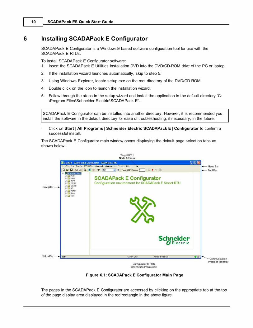
· Click on Start | All Programs | Schneider Electric SCADAPack E | Configurator to confirm asuccessful install.
The SCADAPack E Configurator main window opens displaying the default page selection tabs asshown below.
Figure 6.1: SCADAPack E Configurator Main Page
The pages in the SCADAPack E Configurator are accessed by clicking on the appropriate tab at the topof the page display area displayed in the red rectangle in the above figure.

SCADAPack ES Quick Start Guide 11
7 Initial Power Up of the SCADAPack ES RTU
The SCADAPack ES is powered through a 3 part (SL3) terminal connector located directly beneath theenclosure label DC I/P ± as illustrated in the Figure 7.1 .
A 9-30 Vdc power supply capable of producing 8.8W is required to complete this exercise.
Figure 7.1: Top Panel View of the SCADAPack ES
If possible, wiring connections should be made with the DC source unplugged from the mainspower supply. Only apply power when requested
1. Remove the lid from the SCADAPack ES
2. Identify the two rotary HEX switches adjacent to Port 0.
3. Check that the switches are set to 00.
4. Identify the DC input connector from the enclosure label I/P ±.
5. Connect the output leads from your power supply to I/P ± respecting voltage polarity.
6. Locate the Run LED (located below Port 3).
11

SCADAPack ES Quick Start Guide12
7. Apply power (connect DC Power source to mains) to the RTU and wait for approximately 15seconds. while observing the status of the Run LED.
8. The controller is in normal operation mode when the Run LED steadily emits approximately 1 blinkevery 3 seconds.

SCADAPack ES Quick Start Guide 13
8 Establishing a PC to RTU Communication Link
Communication with a SCADAPack ES RTU can be accomplished through its serial or Ethernetinterfaces.
In this section, an RS-232 serial communication link will be established to the RTU. Optionally, anEthernet communication link will be established to the RTU in Section Ethernet Communication .Configuration of the physical communication interfaces are performed using the SCADAPack EConfigurator.
RS-232 Serial Communication
o Configuring an RS-232 Serial Communication Link
o Testing the RS-232 Serial Communication Link
o Ethernet Communication
o Testing the Ethernet Connection
19
14
15
16
19
24
SCADAPack ES Quick Start Guide14
8.1 RS-232 Serial Communication
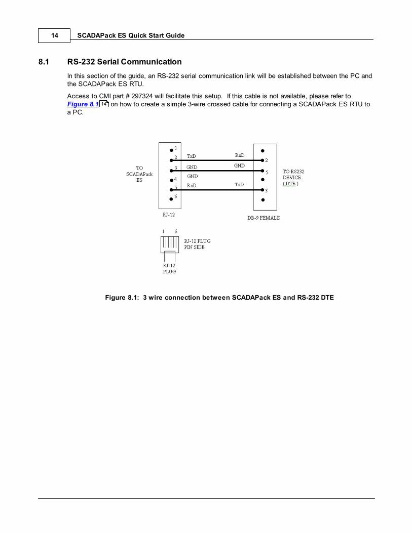
In this section of the guide, an RS-232 serial communication link will be established between the PC andthe SCADAPack ES RTU.
Access to CMI part # 297324 will facilitate this setup. If this cable is not available, please refer to Figure 8.1 on how to create a simple 3-wire crossed cable for connecting a SCADAPack ES RTU toa PC.
Figure 8.1: 3 wire connection between SCADAPack ES and RS-232 DTE
14
SCADAPack ES Quick Start Guide 15
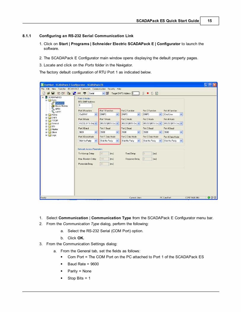
8.1.1 Configuring an RS-232 Serial Communication Link
1. Click on Start | Programs | Schneider Electric SCADAPack E | Configurator to launch thesoftware.
2. The SCADAPack E Configurator main window opens displaying the default property pages.
3. Locate and click on the Ports folder in the Navigator.
The factory default configuration of RTU Port 1 as indicated below.
1. Select Communication | Communication Type from the SCADAPack E Configurator menu bar.
2. From the Communication Type dialog, perform the following:
a. Select the RS-232 Serial (COM Port) option.
b. Click OK.
3. From the Communication Settings dialog:
a. From the General tab, set the fields as follows:
Com Port = The COM Port on the PC attached to Port 1 of the SCADAPack ES
Baud Rate = 9600
Parity = None
Stop Bits = 1

SCADAPack ES Quick Start Guide16
Ignore CTS = True
b. Click OK to save changes and close the dialog.
Returning to the Ports page, the communication link details are now displayed in the PC Comm Portfield in the Target RTU Connection Information at the bottom right of the SCADAPack E Configuratorwindow.
8.1.2 Testing the RS-232 Serial Communication Link
The RS-232 serial communication link will be tested by downloading the factory default configurationfrom RTU battery-backed RAM onto the PC hard drive.
1. Connect Port 1 on the RTU to a RS-232 serial port on the PC using cable # 297234 or a 3-wirecrossed cable.
With the default factory settings, serial RS-232 communication is not possible on Port 0, Port 3 andPort 4.
2. From the SCADAPack E Configurator Menu bar, select File | Read RTU Configuration…
A dialog box appears titled Read Configuration From RTU as shown in Figure 8.5 below.
3. Confirm that fields in this dialog are populated as follows:
File name = ‘config.rtu’
DNP address = 0
Figure 8.5: Read Configuration File Dialog
4. Click on Save.
5. If prompted, select Yes to replacing the existing ‘config.rtu’ file.
16
SCADAPack ES Quick Start Guide 17
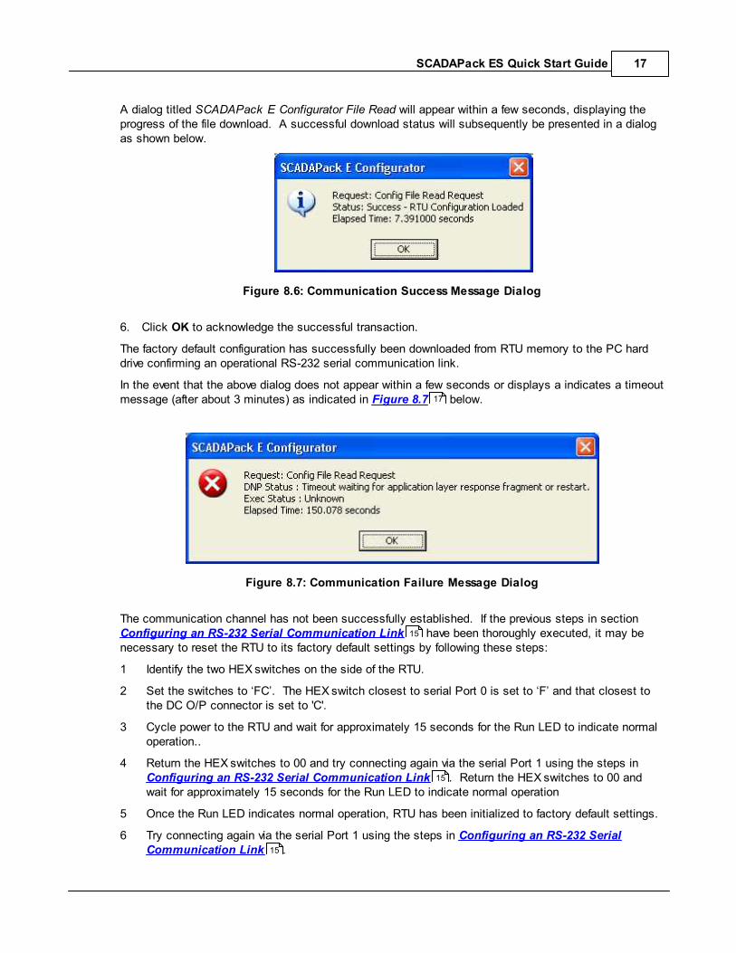
A dialog titled SCADAPack E Configurator File Read will appear within a few seconds, displaying theprogress of the file download. A successful download status will subsequently be presented in a dialogas shown below.
Figure 8.6: Communication Success Message Dialog
6. Click OK to acknowledge the successful transaction.
The factory default configuration has successfully been downloaded from RTU memory to the PC harddrive confirming an operational RS-232 serial communication link.
In the event that the above dialog does not appear within a few seconds or displays a indicates a timeoutmessage (after about 3 minutes) as indicated in Figure 8.7 below.
Figure 8.7: Communication Failure Message Dialog
The communication channel has not been successfully established. If the previous steps in section Configuring an RS-232 Serial Communication Link have been thoroughly executed, it may benecessary to reset the RTU to its factory default settings by following these steps:
1 Identify the two HEX switches on the side of the RTU.
2 Set the switches to ‘FC’. The HEX switch closest to serial Port 0 is set to ‘F’ and that closest tothe DC O/P connector is set to 'C'.
3 Cycle power to the RTU and wait for approximately 15 seconds for the Run LED to indicate normaloperation..
4 Return the HEX switches to 00 and try connecting again via the serial Port 1 using the steps in Configuring an RS-232 Serial Communication Link . Return the HEX switches to 00 andwait for approximately 15 seconds for the Run LED to indicate normal operation
5 Once the Run LED indicates normal operation, RTU has been initialized to factory default settings.
6 Try connecting again via the serial Port 1 using the steps in Configuring an RS-232 SerialCommunication Link .
17
15
15
15

SCADAPack ES Quick Start Guide18
SCADAPack ES Quick Start Guide 19
8.2 Ethernet Communication
In this section, SCADAPack E Configurator will be used to configure on of the 10/100 Base-T Ethernetinterfaces available on the SCADAPack ES RTU.
This port is identified as E1 on the RTU enclosure.
Changes are made to the configuration file ‘config.rtu’ uploaded earlier, saved and written to RTUmemory via the RS-232 serial communication link.
Before proceeding, please obtain a valid IP address and subnet mast from your Network Administrator.
Configuring an Ethernet Communication Link
The IP Routing Table
20
20

SCADAPack ES Quick Start Guide20
8.2.1 Configuring an Ethernet Communication Link
1. Using a CAT5 UTP cable, establish a physical connection between the RTU and the PC via a switch,hub or by connecting the RTU to a wall outlet from your LAN.
2. Confirm that the PC is also connected to a LAN.
3. Launch SCADAPack E Configurator and select the TCP/IP page from the navigator.
4. Enter the IP address and subnet mask obtained from your Network Administrator into the Ethernet 1IP Address and Subnet Mask fields as shown in the sample screen shot below.
Figure 8.8: RTU Ethernet Interface Settings
8.2.2 The IP Routing Table
If the SCADAPack ES is communicating with a peer or host devices residing on a different IP subnetthan the RTU, the IP Routing table needs to be configured.
If not, skip to step 5.
For example, consider the following configuration:
RTU Ethernet port 1 (E1) is configured with IP address 10.10.10.120 and subnet mask255.255.255.0.
Ethernet port on a peer device/PC is configured with IP address 10.10.10.125 and subnet mask255.255.255.0.
In this case, both devices are on the same IP subnet and therefore, the IP Routing table does not need
SCADAPack ES Quick Start Guide 21
to be configured.
On the other hand, consider the peer device/PC with IP address 172.16.22.10 and subnet mask255.255.0.0. In this case, the RTU and peer device/PC are on different subnets. The IP Routing table ofthe RTU needs to be configured to allow communication between the RTU and the peer device/PC. Inthis case an IP address on the RTU's sub-network will be a gateway to the PC device's sub-network,This is the address that needs to be configured.
Performing the following steps is necessary only if the PC and SCADAPack ES RTU are communicatingfrom different subnets.
1. Ask your network administrator for the IP Address of the gateway and the subnet the SCADAPackES is located on.
2. Select the Advanced TCP/IP page from the SCADAPack E Configurator TCP/IP navigator folder.
3. Fill out row 1 of the IP Route Table with the following information:
· Dest. IP Addr: 0.0.0.0
· Subnet Mask: 0.0.0.0
· Dest. Port: Ethernet 1
· Gateway IP: Provided by your network administrator - gateway IP address on the RTU's sub-network
· Metric: 0
4. Click on File | Save from the menu bar to save the changes.
The sample screen shot below shows the IP Route Table filled with the IP Configuration settings of a PCcommunicating with a SCADAPack ES RTU. The RTU is setup to communicate to the remote PCthrough Ethernet port 1.

SCADAPack ES Quick Start Guide22
Figure 8.9: Static IP Routing Table Filled with Host PC ‘ipconfig’ Details
5. Select File | Write RTU Configiguration… from the menu bar to the configuration changes to RTUmemory.
6. Confirm the DNP address on the Write RTU Configuration dialog. If no other changes have beenmade, this field should record 0 as shown in the screen shot below.
Figure 8.10: Write RTU Configuration Dialog
7. Click on OK to initiate the download.
8. A status bar similar to Figure 611 will be displayed followed by a dialog indicating the write request.
9. Click on OK to close the status dialog,

SCADAPack ES Quick Start Guide 23
Figure 8.11: Write RTU Configuration Progress Dialog
10. Upon completion of the configuration change, SCADAPack E Configurator will prompt for the RTU tobe restarted to have the configuration changes take effect.

SCADAPack ES Quick Start Guide24
8.2.3 Testing the Ethernet Connection
The Comm Status LEDs located in the status bar of SCADAPack E Configurator visually describe thestatus of the communication request initiated by the user. The function of each LED is summarized asfollows:
Last request successful
Request in progress
Last request was unsuccessful
Figure 8.12: Request Status Indicators
These LEDs will be used in this section to monitor the status of the Ethernet communication betweenthe RTU and the PC. Alternately, LEDs RX and TX on the RTU casing will blink during TCP/IPcommunication across any RTU communication interface.
To confirm operation of the Ethernet communication channel between the SCADAPack ES RTU and thePC,
1. Select Communication | Communication Type from the SCADAPack E Configurator menu bar.
a. Select UDP/IP (Network)
2. Select Communication | Communication Settings from the SCADAPack E Configurator menu bar.
a. Enter the Controller details (see your Network Administrator for the IP Address or nameand the UDP port number).
b. Select the Advanced Tab.
c. Make changes to the default values as required.
d. Click on OK to close the dialog.
3. The Configurator to RTU Connection Information panel will be updated with the currentcommunication method as shown below.
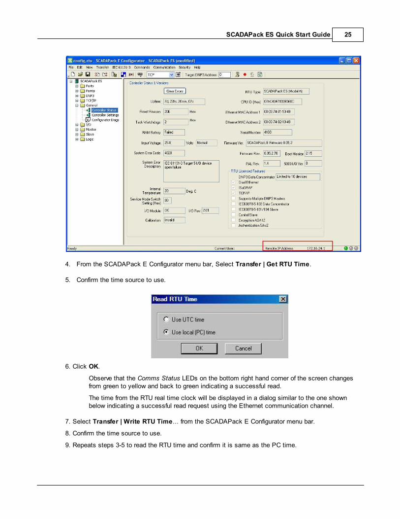
SCADAPack ES Quick Start Guide 25
4. From the SCADAPack E Configurator menu bar, Select Transfer | Get RTU Time.
5. Confirm the time source to use.
6. Click OK.
Observe that the Comms Status LEDs on the bottom right hand corner of the screen changesfrom green to yellow and back to green indicating a successful read.
The time from the RTU real time clock will be displayed in a dialog similar to the one shownbelow indicating a successful read request using the Ethernet communication channel.
7. Select Transfer | Write RTU Time... from the SCADAPack E Configurator menu bar.
8. Confirm the time source to use.
9. Repeats steps 3-5 to read the RTU time and confirm it is same as the PC time.

SCADAPack ES Quick Start Guide26
9 Command Line Diagnostics
The command line mode presents a standard prompt to the user, allowing a selected range ofcommands that can be used to determine the current operating status and configuration details of theRTU, in addition to providing a detailed configuration interface. The exercise in this section involvesconnecting to a SCADAPack ES RTU serial port configured for command line functionality from an ASCIIterminal and executing three useful commands: whoami, ver and status.
1. Connect Port 4 on the RTU to an RS-232 serial port on the PC using cable # 297234 or a 3-wirecrossed cable.
Pay particular notice to the serial Port labels.
2. Launch a terminal emulator program, such as the Hyper Terminal on Windows PCs.
3. Configure the Hyper Terminal communication interface as follows:
· Com Port = The COM Port on the PC attached to Port 1 of the SCADAPack ES
· Port Baud Rate = 9600
· Data Bits = 8
· Parity = None
· Stop Bits = 1
· Flow Control = None
The following is a screen shot of a sample terminal emulator program running of a Windows PC.
Figure 9.1: Configuring Communication Settings in Terminal Emulator Program
Click on OK on the Terminal Emulator Communication dialog.
· Press ENTER on your keyboard to connect to the RTU command prompt as shown below.

SCADAPack ES Quick Start Guide 27
Figure 9.2: SCADAPack ES Command Prompt
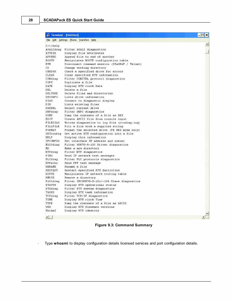
· Type help to display the available list of command.
SCADAPack ES Quick Start Guide28
Figure 9.3: Command Summary
· Type whoami to display configuration details licensed services and port configuration details.
SCADAPack ES Quick Start Guide 29
·
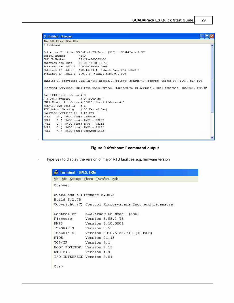
Figure 9.4:’whoami’ command output
· Type ver to display the version of major RTU facilities e.g. firmware version

SCADAPack ES Quick Start Guide30
Figure 9.5: ‘ver’ command output
· Type status to display the RTU status as shown below.
Figure 9.6: ‘status’ command output
Close the Hyper Terminal session.

SCADAPack ES Quick Start Guide 31
10 Reading and Writing RTU DNP Data
The SCADAPack ES is a native DNP3 device. Consequently, the attributes and properties of derived andphysical points are internally recorded in the RTU’s DNP point address space.
Physical points are internal representation of electrical terminations on a Main RTU or SCADAPackES Remote I/O Unit. These may be either Input points or Output points.
Derived points are for RTU internal data. These may be either User points (created by a userdefined configuration) or System points (managed by the RTU operating system)
Each point has a set of Point Attributes, which define how the RTU processes the point. Points with thesame point type (Analog Input for example) share a common set of point attributes. Different point typeshave a different set of attributes. The DNP3 Point Data Class and DNP3 Object Type are examples ofpoint attributes.
Point Properties are generally read only point database fields describing (to the SCADA Master,SCADAPack E Configurator and an ISaGRAF application) a status or characteristic of a point. The current state of a digital point or current value of an analog point is an example of a point attribute.
The exercise in this section involves reading and writing to physical and derived points.

SCADAPack ES Quick Start Guide32
10.1 Reading RTU DNP Data
The current state of a digital point or current value of an analog point, amongst others, are examples ofDNP point attributes that will be read by a user application. The exercise in this section involves readingthe current state or value of some RTU system points.
Table 10.1: Sample RTU DNP System Points
Type Point # System Point Name
Float In 50060 Input Supply Voltage
Float Out 63200 Low Volts Alarm Level
Binary In 50206 Local Input Power Supply Low Alarm
Binary In 50207 Local On Board Battery Low
Analog In 50082 RTU Serial Number
Analog Out 50300 RTU DNP Node Address
Analog In 50010 RTU Up Time (Secs)
1. Apply power to the SCADAPack ES if necessary.
2. Launch the SCADAPack E Configurator software.
3. Select the Point Browser page.
4. Complete the table with the entries Table 10.1 above.
Only the point type and point number need to be entered in the table. Clicking on the Decimal orHex columns for the corresponding DNP point will automatically populate these fields with thecurrent value or state properties of the point.
5. Check that the serial cable is connected to Port 1 if using the serial communication link.
6. Click on Read from the Point Browser page to read the DNP point properties.
A sample screen shot of a populated Point Browser is shown in Figure 10.1 below.
32
32
SCADAPack ES Quick Start Guide 33
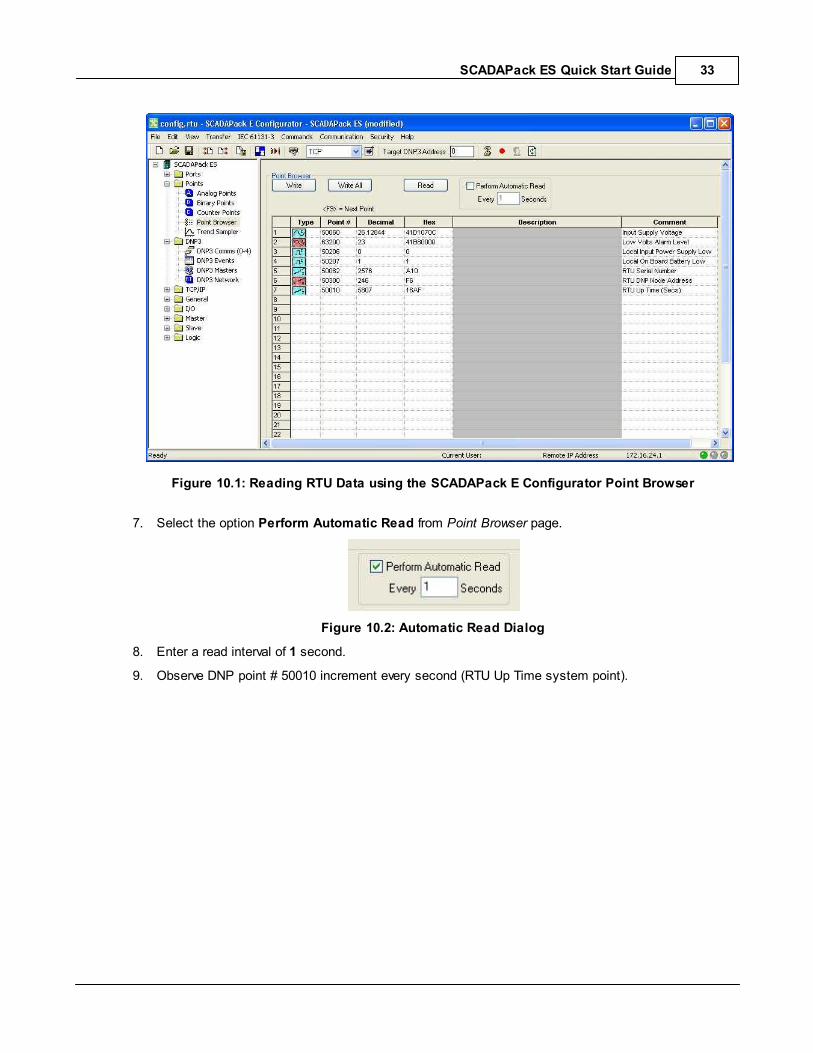
Figure 10.1: Reading RTU Data using the SCADAPack E Configurator Point Browser
7. Select the option Perform Automatic Read from Point Browser page.
Figure 10.2: Automatic Read Dialog
8. Enter a read interval of 1 second.
9. Observe DNP point # 50010 increment every second (RTU Up Time system point).
SCADAPack ES Quick Start Guide34
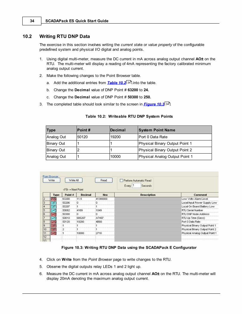
10.2 Writing RTU DNP Data
The exercise in this section involves writing the current state or value property of the configurablepredefined system and physical I/O digital and analog points.
1. Using digital multi-meter, measure the DC current in mA across analog output channel AO± on theRTU. The multi-meter will display a reading of 4mA representing the factory calibrated minimumanalog output current.
2. Make the following changes to the Point Browser table.
a. Add the additional entries from Table 10.2 .into the table.
b. Change the Decimal value of DNP Point # 63200 to 24.
c. Change the Decimal value of DNP Point # 50300 to 250.
3. The completed table should look similar to the screen in Figure 10.3 .
Table 10.2: Writeable RTU DNP System Points
Type Point # Decimal System Point Name
Analog Out 50120 19200 Port 0 Data Rate
Binary Out 1 1 Physical Binary Output Point 1
Binary Out 2 1 Physical Binary Output Point 2
Analog Out 1 10000 Physical Analog Output Point 1
Figure 10.3: Writing RTU DNP Data using the SCADAPack E Configurator
4. Click on Write from the Point Browser page to write changes to the RTU.
5. Observe the digital outputs relay LEDs 1 and 2 light up.
6. Measure the DC current in mA across analog output channel AO± on the RTU. The multi-meter willdisplay 20mA denoting the maximum analog output current.
34
34
SCADAPack ES Quick Start Guide 35
7. Select the Ports page and observe the value of Port 0 Baud rate field.
8. Issue a Reinitialize DNP3 from the Commands menu. This is required for the DNP node addresschange to take effect.
9. Return to the Point Browser.
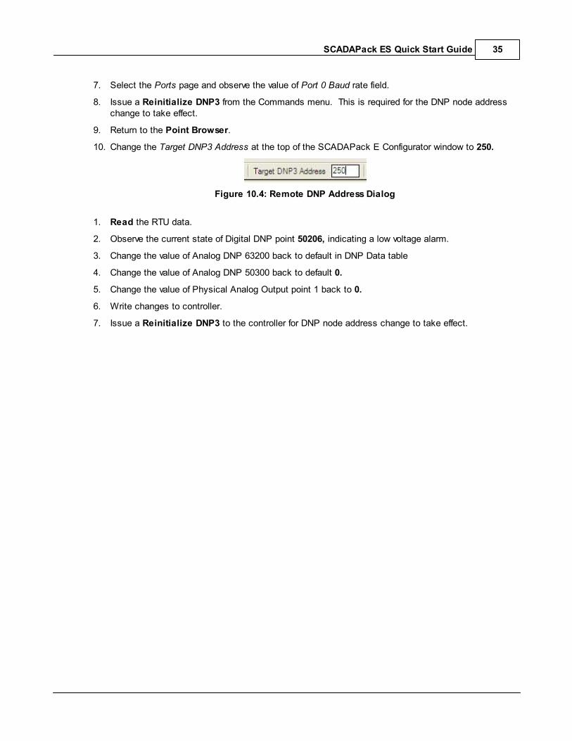
10. Change the Target DNP3 Address at the top of the SCADAPack E Configurator window to 250.
Figure 10.4: Remote DNP Address Dialog
1. Read the RTU data.
2. Observe the current state of Digital DNP point 50206, indicating a low voltage alarm.
3. Change the value of Analog DNP 63200 back to default in DNP Data table
4. Change the value of Analog DNP 50300 back to default 0.
5. Change the value of Physical Analog Output point 1 back to 0.
6. Write changes to controller.
7. Issue a Reinitialize DNP3 to the controller for DNP node address change to take effect.
SCADAPack ES Quick Start Guide36
11 Accessing Physical I/O Data via Modbus
The SCADAPack E RTUs support a native Modbus Slave driver which supports an automatic one to onemapping of DNP points into corresponding Modbus addresses thus allowing communication with otherModbus devices. The ‘Modbus address’ conforms to the Modicon PLC client style register address(protocol address + 1).
Digital input DNP points 1 to 16 are mapped to Modbus registers 10001-10016.
Digital output DNP points 1 to 16 are mapped to Modbus registers 00001-00016.
16-bit analog input DNP points 1 to16 are mapped to Modbus registers 30001 to 30016.
16-bit analog outputs DNP points 1 to 16 are mapped to corresponding holding registers 40001to 40016.
32-bit analog DNP points have to be mapped manually to Modbus registers using the ModbusRegister/32-Bit Point Map located in the Slave | Modbus Page of SCADAPack E Configurator.
The exercise in this section comprises of:
Configuring a serial port as a Modbus Slave.
Performing a DNP to Modbus address mapping for 32-bit analog RTU points.

SCADAPack ES Quick Start Guide 37
11.1 Configuring a Modbus Serial Interface
To configure a Modbus serial interface on the SCADAPack ES,
1. Launch the SCADAPack E Configurator.
2. Select the Port page.
3. Assign the Modbus Slave function to a port from the drop down list as shown in the figure below.
4. View the remaining port parameters.
Figure 11.1: Configuring Serial Port 3 for Modbus Communication
5. Select Slave / Modbus page
6. Enter analog I/O DNP points to Modbus register mapping using the table if using 32-bit analogpoints
7. Confirm the Modbus Slave station address and make changes if necessary.
The same Modbus station number applies if multiple ports on the RTU are configuredfor Modbus Slave
9. Save Configuration file and write the updated file to the controller.
10. Restart the controller.
A master station can now poll data from the SCADAPack ES controller, from the assigned Modbusregisters.
A sample screen shot is shown below. In this example, the SCADAPack ES is assigned a Modbus
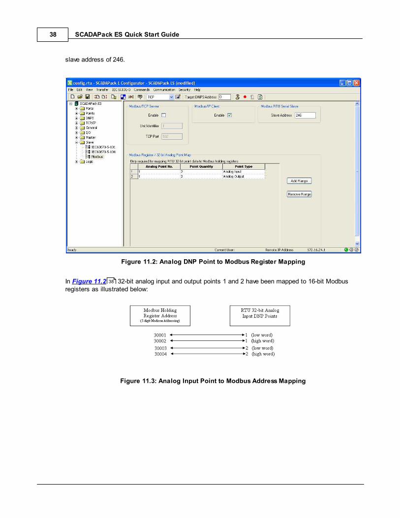
SCADAPack ES Quick Start Guide38
slave address of 246.
Figure 11.2: Analog DNP Point to Modbus Register Mapping
In Figure 11.2 32-bit analog input and output points 1 and 2 have been mapped to 16-bit Modbusregisters as illustrated below:
Figure 11.3: Analog Input Point to Modbus Address Mapping
38
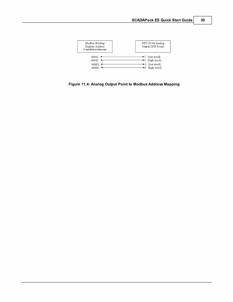
SCADAPack ES Quick Start Guide 39
Figure 11.4: Analog Output Point to Modbus Address Mapping

SCADAPack ES Quick Start Guide40
11.1.1 Reading/Writing to Modbus Registers
Reading and writing to the SCADAPack ES Modbus registers is relatively straight forward once aModbus Slave serial interface has been defined as above.
Using 5-digital Modicon PLC addressing,
Digital inputs are referenced using Modbus registers 10001-19999.
Digital outputs are referenced using Modbus registers 00001–09999.
Analog inputs are referenced using Modbus registers 30001-39999.
Analog outputs are referenced using Modbus holding registers 40001–65535.
When referencing 32-bit analog I/O via Modbus registers two consecutive Modbus holding registers areused to store a 32-bit analog value as illustrated in the previous section.
SCADAPack ES Quick Start Guide 41
12 Related Documentation
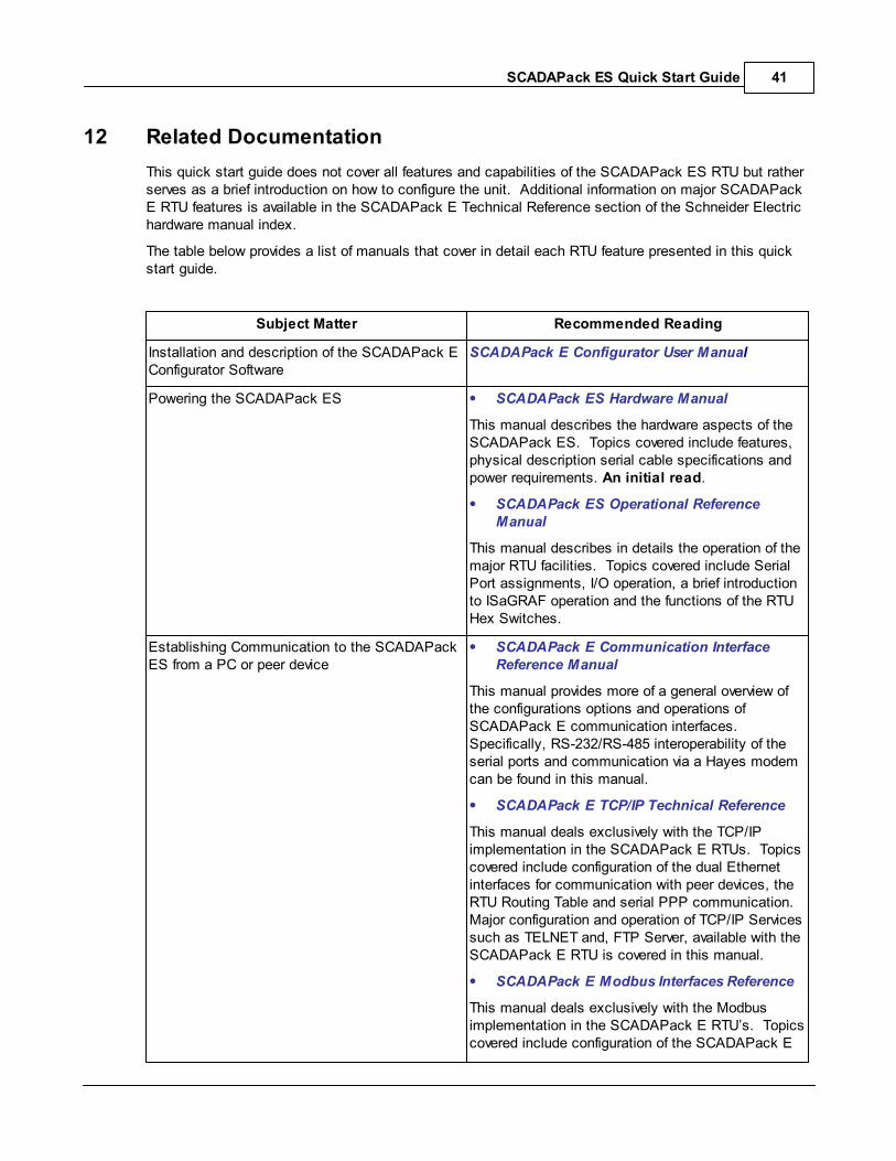
This quick start guide does not cover all features and capabilities of the SCADAPack ES RTU but ratherserves as a brief introduction on how to configure the unit. Additional information on major SCADAPackE RTU features is available in the SCADAPack E Technical Reference section of the Schneider Electrichardware manual index.
The table below provides a list of manuals that cover in detail each RTU feature presented in this quickstart guide.
Subject Matter Recommended Reading
Installation and description of the SCADAPack EConfigurator Software
SCADAPack E Configurator User Manual
Powering the SCADAPack ES SCADAPack ES Hardware Manual
This manual describes the hardware aspects of theSCADAPack ES. Topics covered include features,physical description serial cable specifications andpower requirements. An initial read.
SCADAPack ES Operational ReferenceManual
This manual describes in details the operation of themajor RTU facilities. Topics covered include SerialPort assignments, I/O operation, a brief introductionto ISaGRAF operation and the functions of the RTUHex Switches.
Establishing Communication to the SCADAPackES from a PC or peer device
SCADAPack E Communication InterfaceReference Manual
This manual provides more of a general overview ofthe configurations options and operations ofSCADAPack E communication interfaces. Specifically, RS-232/RS-485 interoperability of theserial ports and communication via a Hayes modemcan be found in this manual.
SCADAPack E TCP/IP Technical Reference
This manual deals exclusively with the TCP/IPimplementation in the SCADAPack E RTUs. Topicscovered include configuration of the dual Ethernetinterfaces for communication with peer devices, theRTU Routing Table and serial PPP communication. Major configuration and operation of TCP/IP Servicessuch as TELNET and, FTP Server, available with theSCADAPack E RTU is covered in this manual.
SCADAPack E Modbus Interfaces Reference
This manual deals exclusively with the Modbusimplementation in the SCADAPack E RTU’s. Topicscovered include configuration of the SCADAPack E

SCADAPack ES Quick Start Guide42
RTU to communicate with peer Modbus devices.
Reading and Writing RTU data. SCADAPack E Configuration TechnicalReference
Contains a wealth of information on the propertiesand attributes of DNP points within the RTUdatabase. An exploration of the completefunctionality of the DNP3 and data processingimplementation in the SCADAPack E RTU.
SCADAPack E DNP3 Technical Reference
Covers the range of features provided by theSCADAPack E implementation of the DNP3protocol. Topics covered include: SCADA dataconfiguration, simultaneous DNP3 operation onmultiple Ports, routing DNP3 frames, Peer-to-Peercommunication and DNP3 over TCP/IP LAN & WANnetworks.

SCADAPack ES Quick Start Guide 43
12.1 SCADAPack ES External Data
SCADAPack ES Remote I/O
The Remote I/O capability of the SCADAPack ES RTU greatly enhances the I/O capability of a singleSCADAPack ESRTU. Details can be found in the SCADAPack ES Remote I/O Technical Referencemanual.
SCADAPack E Data Concentrator
The SCADAPack E RTUs can be licenced for use as a data concentrator.
With these features enabled, the SCADAPack E RTU will communicate to external equipment such asother SCADAPack E Smart RTUs, protection relays, power meters, other small RTUs, IEDs, etc.
When configured as a Data Concentrator, the SCADAPack E RTU is capable of the following:
mapping of controls & inputs between the data concentrator and outstations
integration of remote device event lists with RTU event list
use of configurable serial ports or Ethernet (via TCP/IP) for outstation communications.
communication to multiple outstations supported on same, or different communication channels
quality information from outstation object flags (where available) or status results fromcommunication with an outstation are to mapped to RTU database point quality
time synchronization for devices providing time stamped data
communication status’ that can be mapped to SCADAPack E database points (includes outstationstatus, protocol status codes, communication counters, etc.)
configurable timeout / retry settings
configurable “health poll type” (protocol dependant) & poll interval after lost communications.
DNP3 Routing for direct Master Station or maintenance terminal to remote outstation.
Details can be found in the SCADAPack E Data Concentrator Technical Reference manual.

SCADAPack ES Quick Start Guide44