sbt1000s series user manual - zkteco · pdf file · 2017-05-26sbt1000s series user...
TRANSCRIPT

SB T10 0 0S s er ies
us er m a nua l
Version: 1.0 Date: August, 2016

Speed Gate Barrier Instruction
2
Chapter 1 Brief introduction
This paper introduce SBT1000S series’ Installation and Commissioning .
1.1 Chassis
SBT1000S series use the stainless steel housing, simple and beautiful, anti-corrosion and
rust proof. Chassis size see Figure 1-1.
1.2 Speed gate barrier or arm
There are two types barriers or arms for the SBT1000S. The glass arm see Figure 2-1, the
stainless steel bar arm see Figure 2-2.
Figure 1-1 (mm)

Speed Gate Barrier Instruction
3
Figure 2-1 (mm)
Figure 2-2 (mm)
Speed Gate Barrier Instruction
4
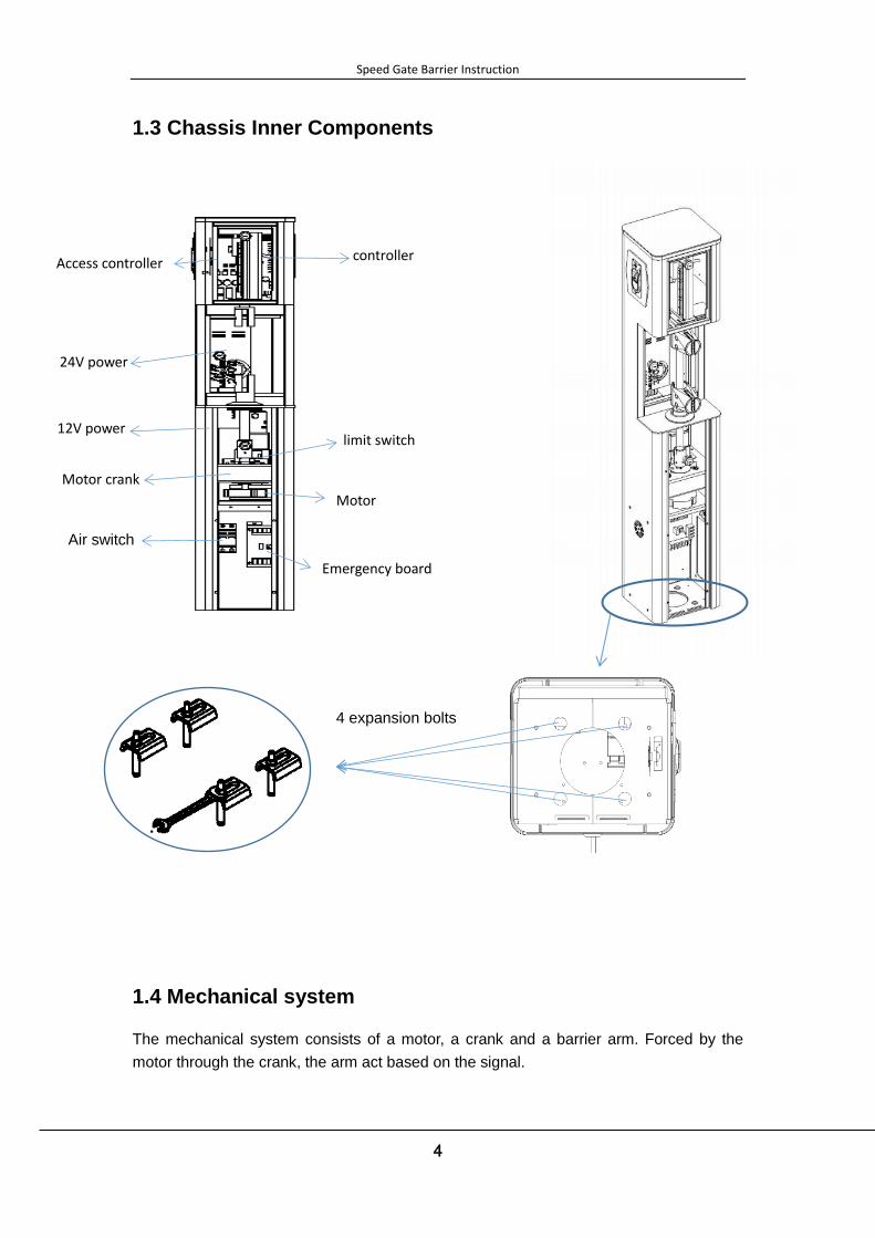
1.3 Chassis Inner Components
1.4 Mechanical system
The mechanical system consists of a motor, a crank and a barrier arm. Forced by the
motor through the crank, the arm act based on the signal.
Air switch
Motor
controller Access controller
Motor crank
12V power
24V power
limit switch
Emergency board
4 expansion bolts
Speed Gate Barrier Instruction
5
1.5 Electric control subsystem
The electric control system consists of reader, control board, infrared sensor, alarm
apparatus, limit switch and power supply installed on the cabinet. .
1. Reader(optional) : Read the user information from card or fingerprint, and transmit
the information to the control board.
2. Control board : Control center of the system, receive information form reader and
infrared sensor, deal with the information and send the command to motor, counter,
indicator light or alarm.
3. Infrared sensor : Detection and protection of pedestrians in the passageway.
4. Alarm apparatus: Giving sound and light alarm when detect intrusion.
5. Limit switch : Control the rotation angle of the gate.
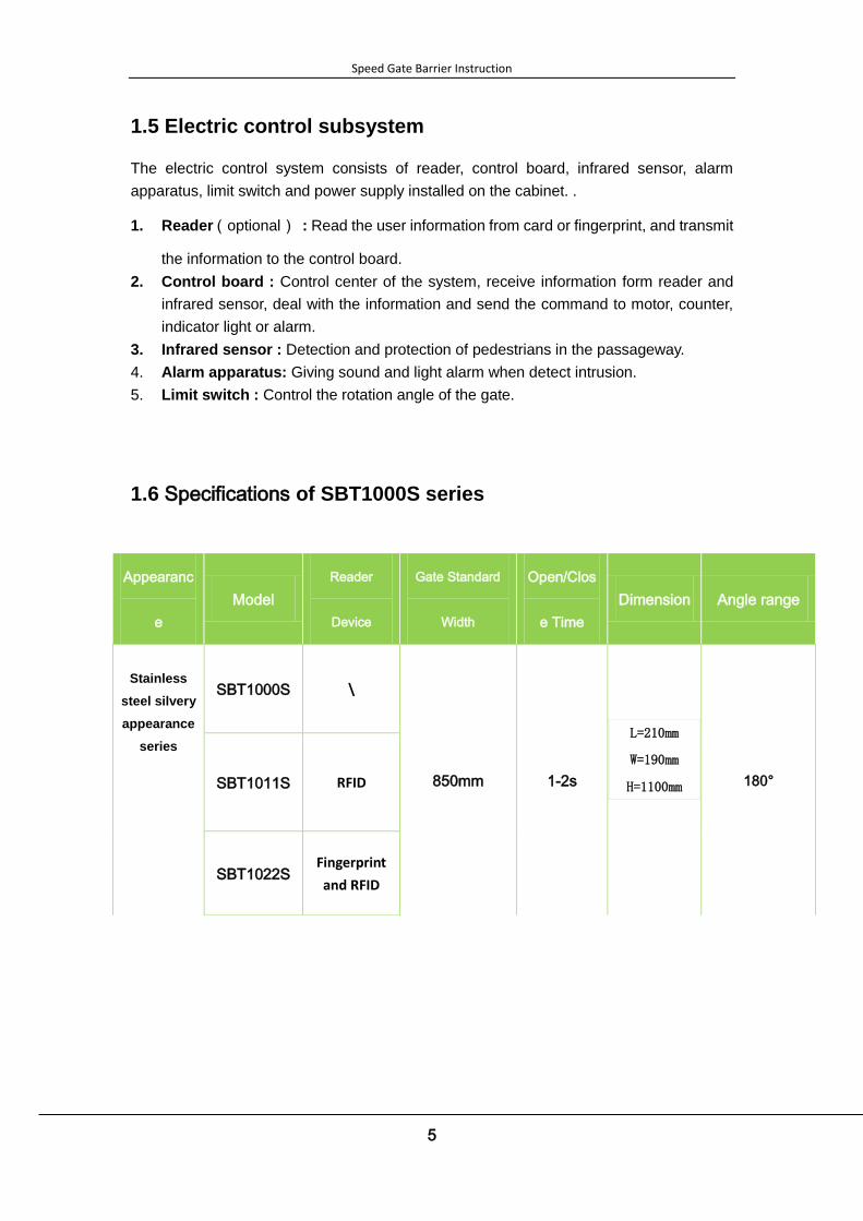
1.6 Specifications of SBT1000S series
Appearanc
e
Model
Reader
Device
Gate Standard
Width
Open/Clos
e Time
Dimension Angle range
Stainless
steel silvery
appearance
series
SBT1000S \
850mm 1-2s
L=210mm
W=190mm
H=1100mm
180° SBT1011S RFID
SBT1022S Fingerprint
and RFID
Speed Gate Barrier Instruction
6
Chapter 2 Product Installation
2.1 Working principles
1. Equipment automatic start self-checking program when power on, gate will close
automatically.
2. Reader transfers the user information to the control board, and incept the feedback
information.
3. Control board receive and compare information with the data stored in our client
database, according to the handling result, controller sends command to drive the motor.
4. The infrared sensor continuously detect until pedestrians pass through the barrier.
5. The buzzer sounds when detect intrusion.
2.2 Installation Precautions
1.Do not push the barrier arm when it closed.
2.Do not sit on the barrier arm.
3.Install the device 50-100mm higher than concrete platform.
4.Do not expose the product in the rain or corrosion environment to prolong its service life.
5.Ensure that the system is grounding before use to avoid security accidents.
6.Please keep the device surface clean and dry, Do not clean with water to avoid short
circuit of electric system.
7.Regularly check the electric system and mechanical system to make sure good
connecting and operating.
2.3 Cable Embedding
Before cable embedding, you should position the machine on the level and solid ground. If
the ground is uneven or the foundation is loose, a concrete construction is necessary.
Make notch on the ground between the machine and the control room, and then embed the
cable with protective sleeves. Finally backfill the notch after test.
Protective sleeve: φ25, black
Cable Standard: RVV3*1.0
Attention:The power wire should be protected with sleeve.
The signal line should keep away from the power wire.

Speed Gate Barrier Instruction
7
2.4 Chassis Installation Guide
1. Verify the accessories on the list and have tools.
2. Position the machine on the right place.
3. Drill on the ground according to the positioning tape .
4. Embedding four expansion bolts (M12) into the positioning holes.
5. Remove the access cover, as shown in Figure 2-4A.
6. Put pads and use a wrench to tighten nuts, as shown in Figure 2-4B.
7. Close the access cover, as shown in Figure2-4C.
8. Install the barrier arm(glass baffle or U-shaped stainless steel pipes), as shown in
Figure2-4D.
Figure 2-4A Figure 2-4B
1 2
Screw pad
Ground Ground
Base
concrete
Chassis
Expansion bolt

Speed Gate Barrier Instruction
8
Figure 2-4C Figure 2-4D
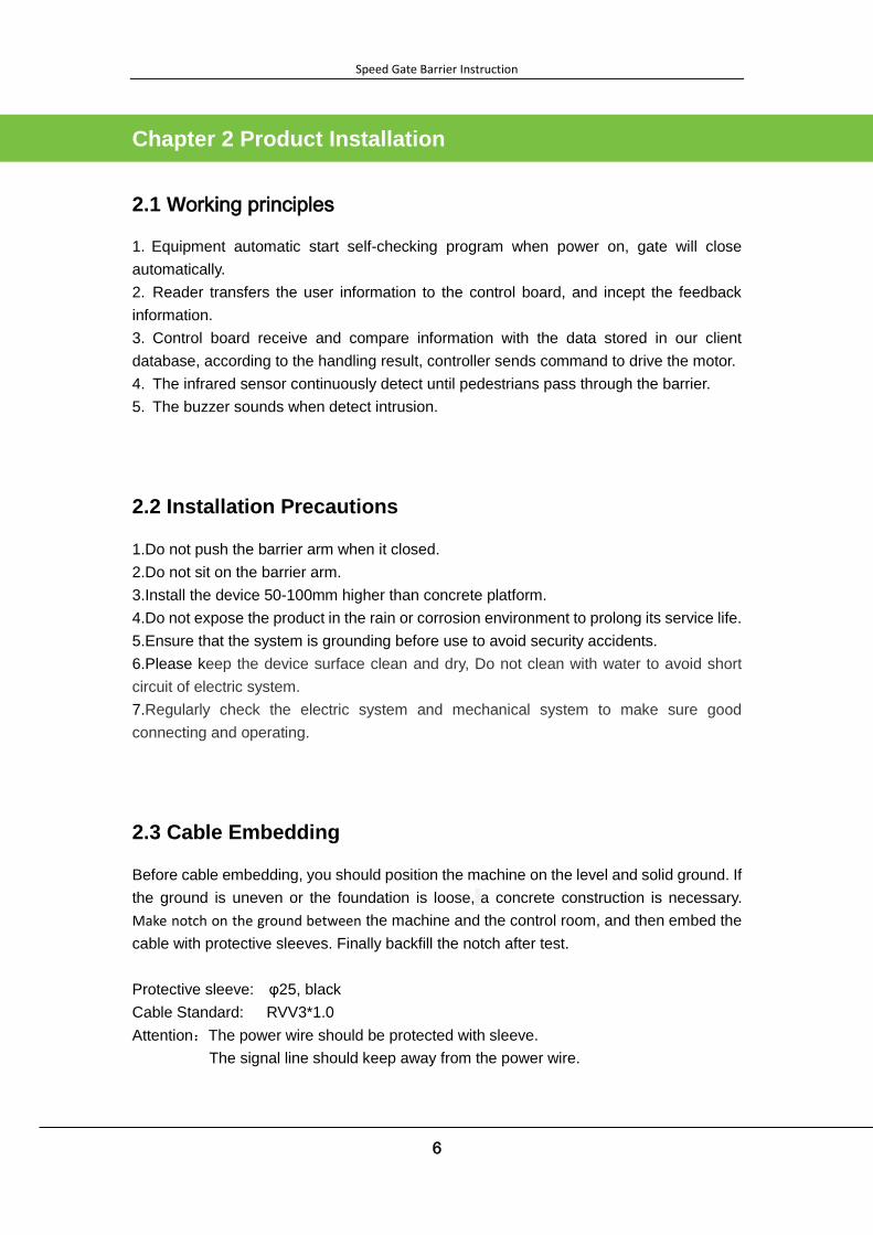
2.5 Barrier arm Installation
The barrier arm can be fixed on the chassis with provided screws. Keep it perpendicular to
the ground and fixed tightly. If fork-shaped rod needed, check device adjusted vertical and
horizontal properly , and move the barrier arm to the horizontal position with hands.
Locate installing place for fork-shaped rod end of arm, and fixed with screws.(Do not
install if not needed).
4 3
U-shaped stainless
steel pipes
Speed Gate Barrier Instruction
9
2.6 System design
2.6.1 Design objectives
1. The system design meet the national and personnel management safety standards.
2. The system adopt advanced pedestrian entrance management mode.
3. The system have good performances on security.
4. The system can manage online or offline.
5. The system is industrial structured and configured flexibly.
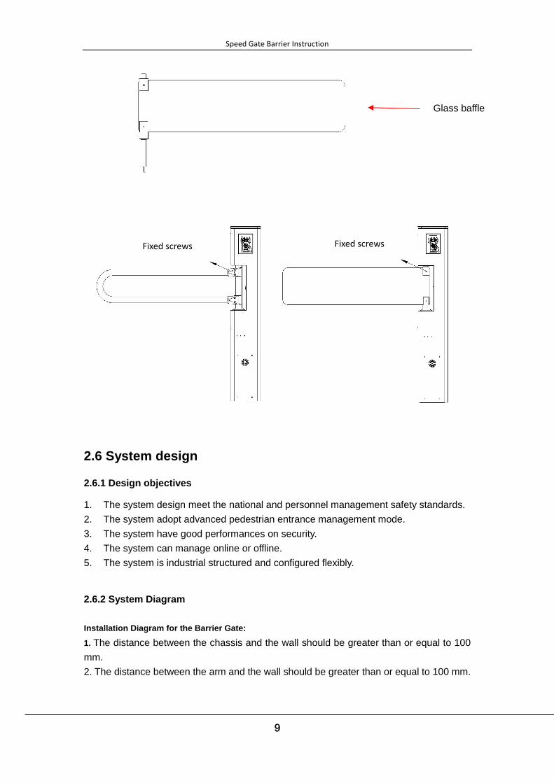
2.6.2 System Diagram
Installation Diagram for the Barrier Gate:
1. The distance between the chassis and the wall should be greater than or equal to 100
mm.
2. The distance between the arm and the wall should be greater than or equal to 100 mm.
Glass baffle
Fixed screws Fixed screws

Speed Gate Barrier Instruction
10

Speed Gate Barrier Instruction
11
Chapter 3 Device Commissioning
3.1 Commissioning Preparations
Wiring follow the wiring diagram, make sure the wiring accurately, then power on.
3.2 Commissioning Project
1. The gate is two-way pass, can be set normally closed or normally open.
2. Power on self-check function : Automatically start self-checking program when power
on, and the barrier arm be reset.
3. Anti-collision function : Gate will open forward when verify successfully even though
you already activate the infrared alarm, and close soon after pass through. But passing
from the opposite direction, the gate will not open.
4. Anti-pinch function : Through the sensor, the machine can sense the pedestrian in
passage way. In the closing process, the arm will be open forcibly if detect the pedestrian.
The barrier arm close only when the sensor detect no pedestrian.
5. Alarm function : Alarm when detect intrusion.
6. Anti-tail function : Only allow one pedestrian through the passage under condition of
one card. Alarm if sensor detect pedestrian without the card.
7. Reverse entry alarm function : Alarm when reverse entry.
8. Emergency function : The system operate via battery when the power failure.
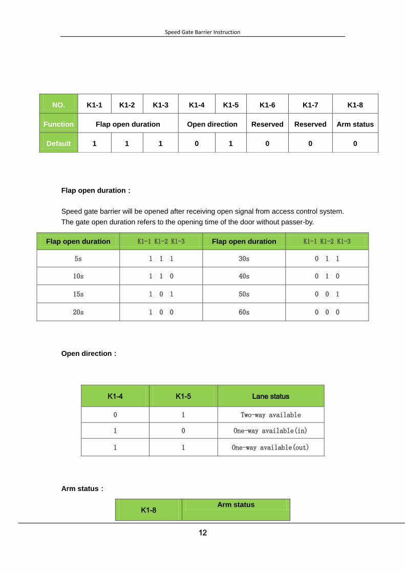
3.3 DIP Switch K1-8 setting
Speed Gate Barrier Instruction
12
Flap open duration:
Speed gate barrier will be opened after receiving open signal from access control system.
The gate open duration refers to the opening time of the door without passer-by.
Flap open duration K1-1 K1-2 K1-3 Flap open duration K1-1 K1-2 K1-3
5s 1 1 1 30s 0 1 1
10s 1 1 0 40s 0 1 0
15s 1 0 1 50s 0 0 1
20s 1 0 0 60s 0 0 0
Open direction:
K1-4 K1-5 Lane status
0 1 Two-way available
1 0 One-way available(in)
1 1 One-way available(out)
Arm status:
K1-8 Arm status
NO. K1-1 K1-2 K1-3 K1-4 K1-5 K1-6 K1-7 K1-8
Function Flap open duration Open direction Reserved Reserved Arm status
Default 1 1 1 0 1 0 0 0

Speed Gate Barrier Instruction
13
0 Normal close
1 Normal open

Speed Gate Barrier Instruction
14
Chapter 4 Common FAQs
NO. Failure phenomena Solution
1
Direct Indicator light is not bright Check the indicator wiring whether right or in good contact.
2
The arm continuous rotate when
power on or not limit after open
1. Check Limit Switch : Check whether the power supply is
normal ;
2. Check Photoelectric Switch: Put a metal plate close to the
detected surface. If the indicator lights then you should adjust
the switch position, if not, you should replace the switch.
3
The arm do not give response
after authentication. The
indicator light work normally.
1.Check the electric motor whether in well-connected. If wiring is
correct, touch the end of electric motor to determine its
operation. If not, replace the main board.
2.Check the signal connection on the control board and check
the indicator light to judge the control board have received the
signal.
3.If all of the indicator light on board is not bright, and the power
be correctly connected, the board damage.
4
The arm not reset or reset
immediately after being opened.
1.Arm reset time-delay after pedestrian pass, it indicates the
photoelectric switch operate abnormally.
2.Check whether the grating plug malfunctions,
3.Check the switch setting on board
5
The arm reset after a long time.
1.Check the switch K1-3 .
2.Check whether the Photoelectric switch terminal output 12V
signal( 0V in Normal).

Speed Gate Barrier Instruction
15
Chapter 5 Device Maintenance
5.1 Chassis maintenance
The chassis is made up of 304 stainless steel and electrolytic steel plate. There may be
rust stains on its surface after using for a long time. Regularly sand the surface along
the grain softly and carefully, Coat the surface with anti-rust oil, Do not cover the infrared
sensor.
5.2 Machine movement maintenance
Cut off power supply before maintenance. Open the lid, clean surface dust, apply butter to
transmission part. Remove the motor, grease the wheel gear, fixed motor on the original
position. Check and tighten the connection parts. Do not adjust the limit switch.
5.2 Power supply maintenance
Cut off power supply and clean surface dust. Check and tighten the loose parts. Check
and replace the damaged wire. Check the technical parameters of each interface. Timely
replace aging electronic components.
Attention : Above repairs and maintenance should be taken by professional technicians.
Make the Device Maintenance Records.
Speed Gate Barrier Instruction
16
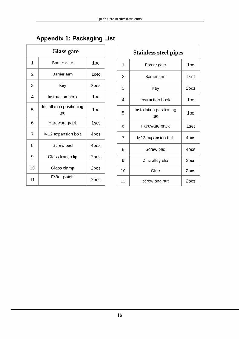
Appendix 1: Packaging List 章 常见故障分析
Glass gate
1 Barrier gate 1pc
2 Barrier arm 1set
3 Key 2pcs
4 Instruction book 1pc
5 Installation positioning
tag 1pc
6 Hardware pack 1set
7 M12 expansion bolt 4pcs
8 Screw pad 4pcs
9 Glass fixing clip 2pcs
10 Glass clamp 2pcs
11 EVA patch
2pcs
Stainless steel pipes
1 Barrier gate 1pc
2 Barrier arm 1set
3 Key 2pcs
4 Instruction book 1pc
5 Installation positioning
tag 1pc
6 Hardware pack 1set
7 M12 expansion bolt 4pcs
8 Screw pad 4pcs
9 Zinc alloy clip 2pcs
10 Glue 2pcs
11 screw and nut 2pcs

Speed Gate Barrier Instruction
17
Appendix 2 Wiring Diagram of the Control Board
Emergency switch
counter
Roof indirect light
electric motor
Power
supply Access controller photoelectric switch
section 1
section 2
section3
Switch K1-8
Attached Figure – A Control Board Diagram
Figure - The default settings of switch

Speed Gate Barrier Instruction
18
Power supply
24
V p
ow
er su
pp
ly
220V/110V input
Attached Figure – B Main supply Diagram
Speed Gate Barrier Instruction
19
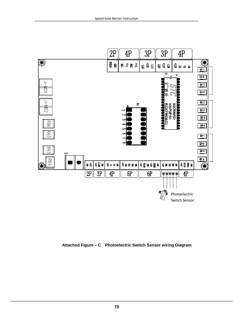
Attached Figure – C Photoelectric Switch Sensor wiring Diagram
Photoelectric
Switch Sensor

Speed Gate Barrier Instruction
20
Motor
Attached Figure – D Motor wiring Diagram

Speed Gate Barrier Instruction
21
Attached Figure – E ID/IC reader wiring Diagram
Access controller
Access
controller
12V supply
ID/IC Reader
Speed Gate Barrier Instruction
22
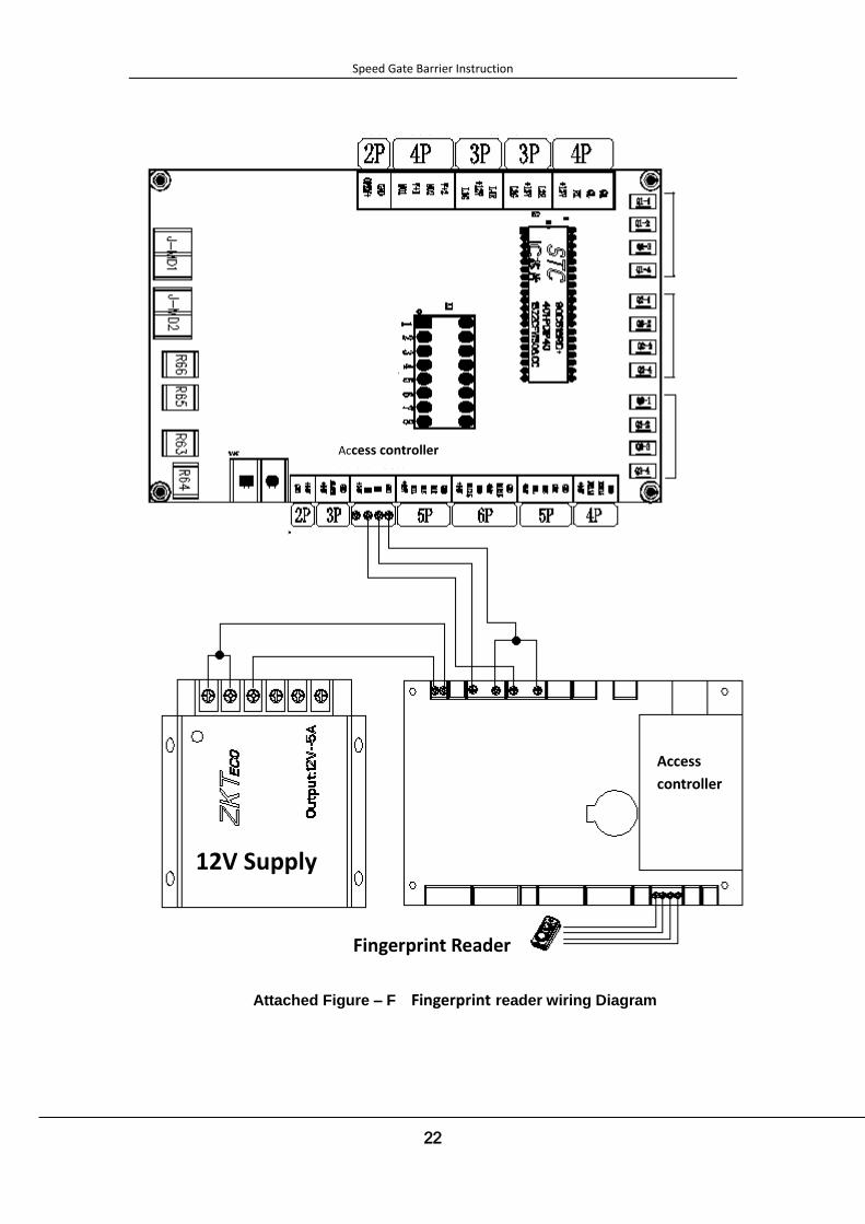
Attached Figure – F Fingerprint reader wiring Diagram
Fingerprint Reader
Access controller
Access
controller
12V Supply
Speed Gate Barrier Instruction
23
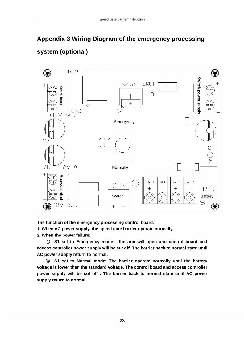
Appendix 3 Wiring Diagram of the emergency processing
system (optional)
The function of the emergency processing control board:
1. When AC power supply, the speed gate barrier operate normally.
2. When the power failure:
① S1 set to Emergency mode : the arm will open and control board and
access controller power supply will be cut off. The barrier back to normal state until
AC power supply return to normal.
② S1 set to Normal mode: The barrier operate normally until the battery
voltage is lower than the standard voltage. The control board and access controller
power supply will be cut off . The barrier back to normal state until AC power
supply return to normal.
Emergency
Normally
Co
ntro
l bo
ard
Switch
po
we
r sup
ply
Battery Switch
Access co
ntro
l

Speed Gate Barrier Instruction
24
Switch power supply
24V DC Power supply
AC Power supply
Attached Figure – H Input AC power wiring Diagram

Speed Gate Barrier Instruction
25
Power input
Attached Figure – I Control board connection wiring Diagram
Emergency switch

Speed Gate Barrier Instruction
26
Acce
ss Co
ntro
ller
Attached Figure – J Access controller connection wiring Diagram

Speed Gate Barrier Instruction
27
12V 5.0Ah/20hr :
12V: Rated voltage of battery;
5Ah: Battery capacity, the battery can work for one hour in the state of 12A,
Battery
Attached Figure – K Battery connection wiring Diagram
Speed Gate Barrier Instruction
28
and work for 12 hour in state of 1A ;
20hr: 20 Hour Rate;