sb 900 manual
TRANSCRIPT

8/8/2019 SB 900 Manual
http://slidepdf.com/reader/full/sb-900-manual 1/142
SB-900User’s Manual
En
Autofocus Speedlight

8/8/2019 SB 900 Manual
http://slidepdf.com/reader/full/sb-900-manual 2/142
A–2
A
P r e p a r a t i o n
About this user’s manual
How to find what you are looking for
You can search for relevant page references using the following methods.
k Table of contents ... (kA-6)You can search by item, such as operation method, flash mode or function.
k Simple search by objective (kA-4)You can search according to your objective without knowing the specific name or
term of the item you are looking for.
k Speedlight functions (kB-4)
You can search for a particular SB-900 function. This is handy when you know thename of a function and want more information.
k Index (kF-22)You can search using the alphabetical index.
k Troubleshooting (kF-2)
You can determine the cause if there is a problem with your Speedlight.
8/8/2019 SB 900 Manual
http://slidepdf.com/reader/full/sb-900-manual 3/142
A–3
A
P r e p a r a t i o n
Terms used in this user’s manual
Default settings: the function and mode settings at the time of purchase are
referred to as the “default settings.”
CLS (Nikon Creative Lighting System): the Nikon Creative Lighting System is
often referred to as “CLS.”
ISO sensitivity: “ISO sensitivity” is a generic term that covers both the imaging
sensitivity of digital SLR cameras and the film sensitivity of 35mm film based
cameras.
Camera and lens combinations
This manual has been compiled with the assumption that the SB-900 will be used in
combination with a camera compatible with CLS (Nikon Creative Lighting System)and a CPU lens.
t Tips on identifying CPU Nikkor lenses
CPU lenses have CPU contacts.
Describes a point to which you should pay particular attention in order
to avoid Speedlight malfunction or mistakes during shooting.
Includes information or tips to make Speedlight use easier.
Marks used in this manualv
t
The SB-900 cannot be used with IX-Nikkor lenses.•
CPU contacts
8/8/2019 SB 900 Manual
http://slidepdf.com/reader/full/sb-900-manual 4/142
A–4
A
P r e p a r a t i o n
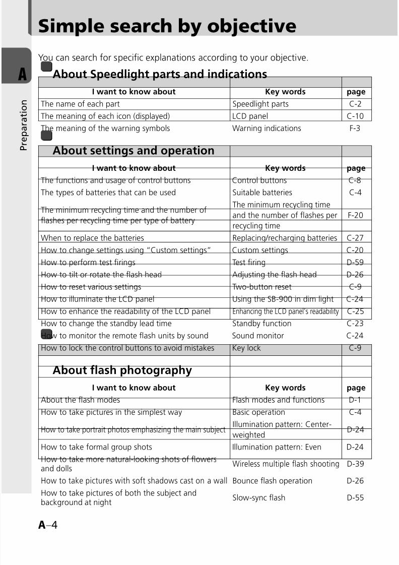
You can search for specific explanations according to your objective.
About Speedlight parts and indications
I want to know about Key words page
The name of each part Speedlight parts C-2
The meaning of each icon (displayed) LCD panel C-10
The meaning of the warning symbols Warning indications F-3
About settings and operation
I want to know about Key words page
The functions and usage of control buttons Control buttons C-8
The types of batteries that can be used Suitable batteries C-4
The minimum recycling time and the number of
flashes per recycling time per type of battery
The minimum recycling time
and the number of flashes per
recycling time
F-20
When to replace the batteries Replacing/recharging batteries C-27
How to change settings using “Custom settings” Custom settings C-20
How to perform test firings Test firing D-59
How to tilt or rotate the flash head Adjusting the flash head D-26
How to reset various settings Two-button reset C-9
How to illuminate the LCD panel Using the SB-900 in dim light C-24
How to enhance the readability of the LCD panel Enhancing the LCD panel’s readability C-25
How to change the standby lead time Standby function C-23
How to monitor the remote flash units by sound Sound monitor C-24
How to lock the control buttons to avoid mistakes Key lock C-9
About flash photography
I want to know about Key words page
About the flash modes Flash modes and functions D-1
How to take pictures in the simplest way Basic operation C-4
How to take portrait photos emphasizing the main subjectIllumination pattern: Center-
weightedD-24
How to take formal group shots Illumination pattern: Even D-24
How to take more natural-looking shots of flowersand dolls
Wireless multiple flash shooting D-39
How to take pictures with soft shadows cast on a wall Bounce flash operation D-26
How to take pictures of both the subject andbackground at night Slow-sync flash D-55
Simple search by objective
8/8/2019 SB 900 Manual
http://slidepdf.com/reader/full/sb-900-manual 5/142
A–5
AA
B
C
D
E
F
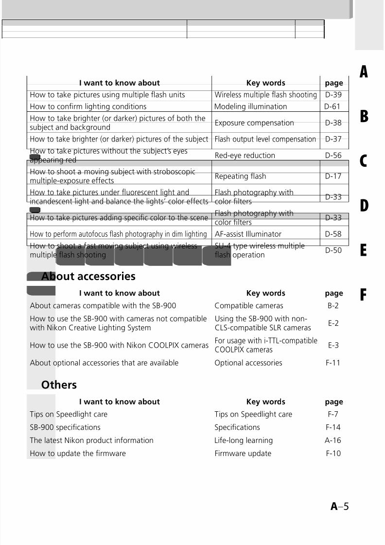
I want to know about Key words page
How to take pictures using multiple flash units Wireless multiple flash shooting D-39How to confirm lighting conditions Modeling illumination D-61
How to take brighter (or darker) pictures of both thesubject and background
Exposure compensation D-38
How to take brighter (or darker) pictures of the subject Flash output level compensation D-37
How to take pictures without the subject’s eyesappearing red
Red-eye reduction D-56
How to shoot a moving subject with stroboscopicmultiple-exposure effects
Repeating flash D-17
How to take pictures under fluorescent light andincandescent light and balance the lights’ color effects
Flash photography withcolor filters
D-33
How to take pictures adding specific color to the sceneFlash photography withcolor filters
D-33
How to perform autofocus flash photography in dim lighting AF-assist Illuminator D-58
How to shoot a fast moving subject using wirelessmultiple flash shooting
SU-4 type wireless multipleflash operation
D-50
About accessories
I want to know about Key words page
About cameras compatible with the SB-900 Compatible cameras B-2
How to use the SB-900 with cameras not compatiblewith Nikon Creative Lighting System
Using the SB-900 with non-CLS-compatible SLR cameras
E-2
How to use the SB-900 with Nikon COOLPIX camerasFor usage with i-TTL-compatibleCOOLPIX cameras
E-3
About optional accessories that are available Optional accessories F-11
OthersI want to know about Key words page
Tips on Speedlight care Tips on Speedlight care F-7
SB-900 specifications Specifications F-14
The latest Nikon product information Life-long learning A-16
How to update the firmware Firmware update F-10

8/8/2019 SB 900 Manual
http://slidepdf.com/reader/full/sb-900-manual 6/142
A–6
A
P r e p a r a t i o n
Contents
Preparation
About this user‘s manual ......................................................................A-2
How to find what you are looking for .................................................. A-2
Simple search by objective ....................................................................A-4
For your safety ......................................................................................A-8
Check before Use ...............................................................................A-14
About the SB-900
SB-900 features ....................................................................................B-2
Main functions ......................................................................................B-4
OperationSpeedlight parts ....................................................................................C-2
Basic operations ....................................................................................C-4
Control buttons ....................................................................................C-8
LCD ....................................................................................................C-10
Custom functions and settings ............................................................C-20
Batteries .............................................................................................C-27
Flash modes and functions
i-TTL mode ............................................................................................D-2
Auto aperture flash ...............................................................................D-5
Non-TTL auto flash................................................................................D-8
Distance-priority manual flash .............................................................D-11
Manual mode .....................................................................................D-14
Repeating flash ...................................................................................D-17
Determining the aperture, flash output level and shooting distancein the Distance priority, Manual and Repeating flash mode..................D-22
Switching illumination pattern ............................................................D-24
Bounce flash operation .......................................................................D-26
Taking close-up photographs with bounce-down flash ........................D-30
Flash photography with color filters ....................................................D-33
Flash output level compensation and exposure compensation .............D-37
Wireless multiple flash shooting ..........................................................D-39
AA
BB
CC
DD

8/8/2019 SB 900 Manual
http://slidepdf.com/reader/full/sb-900-manual 7/142
A–7
AA
B
C
D
E
F
Flash shooting in Advanced Wireless Lighting .............................D-43
SU-4 type wireless multiple flash shooting ..................................D-50
Available functions to be set on the camera ........................................D-55
Auto FP High-Speed Sync modeFlash Value Lock (FV Lock)
Slow-sync flash
Red-eye reduction/Red-eye reduction with slow-sync flash
Rear-curtain sync
Flash shooting support functions .........................................................D-57
Power zoom function
AF-Assist Illuminator
Setting the ISO sensitivity
Test firing functionModeling illuminator function
FX-/DX selection
For use with cameras other than CLS compatibleSLR cameras
Using the SB-900 with non-CLS-compatible SLR cameras ...................... E-2
For usage with i-TTL-compatible COOLPIX cameras ............................... E-3
Tips on Speedlight care and reference information
Troubleshooting .................................................................................... F-2
Notes on continuous flash shooting ...................................................... F-5
Thermal Cut-out ................................................................................... F-6
Tips on Speedlight care ......................................................................... F-7
Notes on batteries................................................................................. F-8
About the LCD panel ............................................................................ F-9
Updating firmware .............................................................................. F-10
Optional accessories ............................................................................ F-11
Specifications ...................................................................................... F-14
Index .................................................................................................. F-22
•
•
••
•
•
•
•
•
•
••
•
EE
FF
8/8/2019 SB 900 Manual
http://slidepdf.com/reader/full/sb-900-manual 8/142
A–8
A
P r e p a r a t i o n
For your safety
Before using your product, please read the following safety precautions carefullyand thoroughly to ensure correct and safe use and to help prevent damage to yourNikon product or injury to yourself or others.
For quick reference by those who use the product, please keep these safety
instructions near the product.In this manual, safety instructions are indicated with these symbols:
WARNINGDisregarding instructions marked with this symbol could result in personal injury, ordeath and property damage.
CAUTIONDisregarding instructions marked with this symbol could result in property damage.
WARNINGS for SpeedlightsIf corrosive liquids seep from the batteries and get in your eyes,immediately wash your eyes with running water and consult with adoctor. Your eyes could be seriously damaged if they are not treated quickly.
If corrosive liquids seep from the batteries and come in contact withyour skin or clothes, wash immediately with running water. Prolongedcontact could injure your skin.
Never attempt to disassemble or repair the flash unit by yourself, as thiscould result in you receiving an electric shock and could also cause the unit to
malfunction; such malfunction could lead to personal injury.If the flash unit is dropped and damaged, do not touch any exposedinterior metal parts. Such parts, especially the Speedlight’s capacitor andassociated parts, could be in a high-charge state and if touched could cause anelectric shock. Disconnect the power or remove the batteries and be sure thatyou do not touch any of the product’s electrical components, and then bringthe flash unit to your local Nikon dealer or authorized service center for repair.
If you detect heat, smoke or notice a burning smell, immediately stopoperation and remove the batteries to prevent the unit from catching on
fire or melting. Allow the flash unit to cool down so that you can safely touchit and remove the batteries. Then bring the unit to your local Nikon dealer orauthorized service center for repair.
The flash unit should never be submerged in liquid or exposed to rain,saltwater or moisture unless it is properly protected from the liquidsand moisture. Underwater use requires a certified underwater housing.
If water or moisture gets inside the unit, this could cause the unit to catchon fire or cause an electric shock. In such instances you should immediatelyremove the batteries from the Speedlight and then bring the unit to your local
Nikon dealer or authorized service center for repair.Note: electronic devices that are penetrated by water or moisture are often not economically repairable.
1.
2.
3.
4.
5.
6.

8/8/2019 SB 900 Manual
http://slidepdf.com/reader/full/sb-900-manual 9/142
A–9
A
P r e p a r a t i o n
Do not use the unit in the presence of flammable or explosive gas.
If the flash unit is operated in areas where there is a flammable gas, includingpropane, gasoline and dust, it could cause an explosion or fire.
Do not fire the flash unit directly at the driver of a moving car, as thiscould temporarily impair the driver’s vision and cause an accident.
Do not fire the flash unit directly into the eyes of someone that is atclose range, as it could damage the retinas of their eyes. Never fire the flashunit closer than 1 meter from infants.
Do not fire the unit while the flash head is touching a person or object.
Such use can result in the person being burned, and/or their clothes ignitingfrom the heat of the flash’s firing.
Keep small accessories out of the reach of children to avoid the possibility
of the accessory being swallowed. If an accessory is accidentally swallowed,immediately consult with a doctor.
Use only the batteries specified in this user’s manual. Batteries otherthan those specified could leak corrosive liquids, explode or catch on fire orotherwise not perform satisfactorily.
Do not mix battery types, brands or old and new batteries, as thebatteries could leak corrosive liquids, explode or catch on fire. When usingmore than one battery in a product, always use identical batteries that werepurchased at the same time.
Non-rechargeable batteries such as manganese, alkaline-manganeseand lithium batteries should never be charged in a battery charger because they could leak corrosive liquids, explode or catch on fire.
When using standard size (AA, AAA, C, D) or other commonrechargeable batteries such as NiCd and Ni-MH battery types, or whenrecharging them, be sure to use only the battery charger specifiedby the battery maker and read the instructions thoroughly. Do notrecharge these batteries with their terminals reversed in the chargeror before the batteries have cooled off sufficiently because they couldleak corrosive liquids, explode or catch on fire. The same caution also appliesto using the rechargeable batteries that may be supplied by the photoproduct’s manufacturer.
7.
8.
9.
10.
11.
12.
13.
14.
15.

8/8/2019 SB 900 Manual
http://slidepdf.com/reader/full/sb-900-manual 10/142

8/8/2019 SB 900 Manual
http://slidepdf.com/reader/full/sb-900-manual 11/142
A–11
A
P r e p a r a t i o n
If corrosive liquids seep from the batteries and come in contact withyour skin or clothes, wash immediately with running water. Prolongedcontact could injure your skin.
Always follow the warnings and instructions printed on the batteries to
avoid activities that could cause the batteries to leak corrosive liquids, generateheat or catch on fire.
Be sure to use only batteries specified in this user’s manual, to avoid thepossibility of batteries leaking corrosive liquids, generating heat or exploding.
Never open the casing surrounding batteries or use batteries whosecasing has been breached as such batteries could leak corrosive liquids,generate heat or explode.
Keep batteries out of the reach of children to help avoid the possibilityof them being swallowed. If a battery is accidentally swallowed, immediately
consult with a doctor.Batteries should not be submerged in water, exposed to rain,moisture or saltwater unless they are properly protected from the wetenvironment. If water or moisture gets inside the batteries, this could causethem to leak corrosive liquids or generate heat.
Do not use any battery that appears abnormal in any way, includinga change in color or shape. Such batteries could leak corrosive liquids orgenerate heat.
Stop recharging rechargeable batteries if you notice that recharging isnot completed within the specified time to help prevent the possibility ofthe battery leaking corrosive liquids or generating heat.
When recycling or disposing of batteries, be sure to insulate theirterminals with tape. If the battery’s positive and negative terminalsshortcircuit after coming into contact with metallic objects, it could cause fire,heat generation or an explosion. Dispose of used batteries in accordance withlocal government regulations
Non-rechargeable batteries should never be charged in a batterycharger because they could leak corrosive liquids or generate heat.
Remove dead batteries from your equipment immediately, as they couldleak corrosive liquids, generate heat or explode.
8.
9.
10.
11.
12.
13.
14.
15.
16.
17.
18.
8/8/2019 SB 900 Manual
http://slidepdf.com/reader/full/sb-900-manual 12/142
A–12
A
P r e p a r a t i o n
For your safety
CAUTION for BatteriesDo not throw or apply strong physical shocks to the batteries as this couldcause batteries to leak corrosive liquids, generate heat or explode.
Symbol for separate collection applicable in European countries
This symbol indicates that this product is to be collected separately.The following apply only to users in European countries.
This product is designated for separate collection at an
appropriate collection point. Do not dispose of as household
waste
For more information, contact the retailer or the local authorities
in charge of waste management.
•
•

8/8/2019 SB 900 Manual
http://slidepdf.com/reader/full/sb-900-manual 13/142
A–13
A
P r e p a r a t i o n

8/8/2019 SB 900 Manual
http://slidepdf.com/reader/full/sb-900-manual 14/142
A–14
A
P r e p a r a t i o n
Check before Use
Foreword
Thank you for purchasing the Nikon Speedlight SB-900. To get the most out of your
Speedlight, please read this user’s manual and the separate booklet “A collection ofexample photos” thoroughly before use.
This user’s manual explains SB-900 functions, operation methods, specifications,
etc., and the separate “A collection of example photos” provides an overview of
the SB-900’s flash-shooting capabilities with example photos.
In addition, keep your camera user’s manual handy for quick reference.
Included items
The SB-900 comes with the following accessories. Check that all items are included
before use.
❑ Speedlight Stand AS-21
❑ Nikon Diffusion Dome SW-13H
❑ Color Filter Set SJ-900
❑ Color Filter Holder SZ-2
❑ Soft Case SS-900
❑ User’s manual (this manual)
❑ A collection of example photos
❑Warranty card
SB-900
Color Filter HolderSZ-2
Nikon Diffusion DomeSW-13H
Soft CaseSS-900
Speedlight StandAS-21
Color Filter SetSJ-900

8/8/2019 SB 900 Manual
http://slidepdf.com/reader/full/sb-900-manual 15/142
A–15
A
P r e p a r a t i o n
Tips on using the Speedlight
Take trial shots
Make trial shots before photographing important occasions like weddingsor graduations.
Have Nikon spot-check your Speedlight regularlyNikon recommends that you have your Speedlight serviced by an authorized dealer
or service center at least once every two years.
Use your Speedlight with Nikon equipmentThe Nikon Speedlight SB-900’s performance has been optimized for use with Nikon
brand cameras/accessories including lenses.
Camera/accessories made by other manufacturers may not meet Nikon’s criteria forspecifications, and nonconforming cameras/accessories could damage the SB-900’s
components. Nikon cannot guarantee the SB-900’s performance when used with
non-Nikon products.

8/8/2019 SB 900 Manual
http://slidepdf.com/reader/full/sb-900-manual 16/142
A–16
A
P r e p a r a t i o n
Check before Use
Life-long learning
As part of Nikon’s “Life-long learning” commitment to ongoing product support and
education, continually-updated information is available on-line at the following sites:For users in the U.S.A.:
http://www.nikonusa.com/
For users in Europe:
http://www.europe-nikon.com/support
For users in Asia, Oceania, the Middle East, and Africa:
http://www.nikon-asia.com/ Visit these sites to keep up-to-date with the latest product information, tips,
answers to frequently-asked questions (FAQs), and general advice on digital
imaging and photography. Additional information may be available from the Nikon
representative in your area. See the URL below for contact information:
http://nikonimaging.com/
•
•
•
8/8/2019 SB 900 Manual
http://slidepdf.com/reader/full/sb-900-manual 17/142
B–1
B
A b o u t
t h e S B - 9 0 0
B–1
BThis section explains the features and key functions ofthe SB-900.
About the SB-900
SB-900 features......................................................B-2
Main functions ......................................................B-4
•
•
B–1

8/8/2019 SB 900 Manual
http://slidepdf.com/reader/full/sb-900-manual 18/142
B–2
B
A b o u t
t h e S B - 9 0 0
SB-900 features
Features of the SB-900
The SB-900 is a high-performance CLS-compatible Speedlight with a large guide
number of 34/48 (ISO 100/200, m) (111.5/157.5, ft.) (at the 35 mm zoom positionin Nikon FX format with standard illumination pattern, 20°C/68°F.)
Combined with a CLS-compatible camera, the SB-900 can easily perform various
types of flash operations, such as i-TTL auto flash and wireless multiple flash
(kD-39).
Three types of illumination patterns (standard, center-weighted and even) are
available to match different shooting preferences.
FX/DX selection enables the setting of the light distribution angle in accordance
with the camera’s image area between FX- and DX-formats, and provideseffective and high-quality lighting.
Power zoom function automatically adjusts the zoom position to match the lens
focal length from 17 mm to 200 mm (in FX format)/12 mm to 200 mm (in DX
format). When the built-in wide-flash adapter is used or the Nikon Diffusion
Dome is attached, the zoom position is automatically set to match a wideangle
lens with much shorter focal length.
Bounce flash (kD-26) or close-up flash photography can be easily performed
(kD-30).
Custom functions are provided to allow for various settings (kC-20).
Compatible cameras
The SB-900 has been optimized for use with CLS-compatible SLR cameras.
For usage with non-CLS-compatible SLR cameras and with i-TTL-compatible
COOLPIX cameras, see “Using the SB-900 with non-CLS-compatible SLR
cameras.” (kE-1)
•
•
•
•
•
•
•
D3, D700, D2 Series, D300, D200, D80, D70 Series, D60, D50,
D40 Series, F6, etc.
CLS-compatible SLR cameras
COOLPIX 8800, COOLPIX 8400, COOLPIX P5000,
COOLPIX P5100, etc.
i-TTL-compatible COOLPIX cameras

8/8/2019 SB 900 Manual
http://slidepdf.com/reader/full/sb-900-manual 19/142
B–3
B
A b o u t
t h e S B - 9 0 0
What is the Nikon Creative Lighting System (CLS)?
The SB-900 features the Nikon Creative Lighting System (CLS). This system offers
additional flash shooting possibilities with digital cameras by taking advantage ofyour camera’s digital communication capabilities. CLS is available when the SB-900
is used with compatible Nikon cameras.
The SB-900 offers these major features:
i-TTL mode
This is a Nikon Creative Lighting System TTL auto flash mode. Monitor pre-flashes
are fired at all times. The subject is correctly exposed by the light from the flash
lighting and the exposure is less affected by ambient light (kD-2).
Advanced Wireless LightingWith Advanced Wireless Lighting, wireless multiple flash operation in the TTL (i-TTL)
mode can be accomplished with CLS-compatible digital SLRs. In this mode, you
can divide the remote flash units into three groups and control the flash output
independently for each group, expanding your range of creative multiple-flash
shooting techniques (kD-43).
FV Lock (Flash Value Lock)
Flash Value, or “FV,” is the amount of flash exposure for the subject. Using FV Lockwith compatible cameras, you can lock in the appropriate flash exposure for the
main subject. This flash exposure is locked in, even if you change the aperture or
composition, or zoom the lens in and out. (kD-55).
Flash Color Information Communication
When the SB-900 is used with compatible digital SLRs, color temperature
information is automatically transmitted to the camera. In this way, the camera’s
white balance is automatically adjusted to give you the correct color temperature
when taking photographs with the SB-900.
Auto FP High-Speed Sync
High-Speed flash synchronization at a compatible camera’s highest shutter speed is
possible. This is useful when you want to use a wider aperture to achieve shallow
depth of field to blur the background (kD-55).
AF-Assist illuminator
In autofocus operation, the SB-900 emits AF-Assist illumination, which matches the
wider AF area of CLS-compatible cameras. With cameras supporting this function,autofocus photography in dim lighting is possible even when the camera’s focus
point (focus area) is changed (kD-58).
■
■
■
■
■
■
8/8/2019 SB 900 Manual
http://slidepdf.com/reader/full/sb-900-manual 20/142
B–4
B
A b o u t
t h e S B - 9 0 0
Main functions
Flash modes and functions on the SB-900
i-TTL mode (kD-2)
The camera controls the SB SB-900’s flash output level by measuring the lightreflected from the subject when the SB-900 fires a series of monitor pre-flashes.
Auto-Aperture flash mode (kD-5)The SB-900 controls the flash output level by measuring the flash illumination reflectedback from the subject using the sensor for Non-TTL auto flash and combining this withinformation from the camera, such as the ISO sensitivity and the aperture setting.
Non-TTL Auto flash mode (kD-8)The SB-900 controls the flash output level by measuring the flash illumination
reflected back from the subject using the sensor for Non-TTL auto flash. Distance Priority manual flash mode (kD-11)
If you preset the aperture and the distance to the subject, the SB SB-900 willautomatically take control of correct light output.
Manual flash mode (kD-14)By setting the aperture and the flash output level, you can manually set theexposure and the distance to the subject.
Repeating flash mode (kD-17)
The SB-900 fires repeatedly to create stroboscopic multiple-exposure effects. Thisoperation is useful when shooting fast-moving subjects.
Switching illumination pattern (kD-24)You can select one of three types of illumination pattern (standard, center-weightedand even) in accordance with your objective.
Bounce flash (kD-26)By tilting or rotating the flash head, you can bounce the light off a ceiling or wall tomake use of reflected light.
Close-up flash photography (kD-30)Close up flash photography can be achieved with use of the built-in wide-flashadapter and the flash head tilted down.
Using color filters (kD-33)You can compensate for the color of a light source or create interesting effects bychanging the light from the filters to a different color.
Flash output level compensation/Exposure compensation (kD-37)Flash output level compensation is performed by modifying the flash output level forthe flash illuminated subject only. Exposure compensation is performed by intentionallymodifying the correct exposure to modify both the subject and background exposure.
8/8/2019 SB 900 Manual
http://slidepdf.com/reader/full/sb-900-manual 21/142
B–5
B
A b o u t
t h e S B - 9 0 0
Wireless multiple flash (kD-39)
Advanced Wireless Lighting (kD-43)In this mode, you can divide the remote flash units into three groups and set the
flash mode and flash output level compensation values separately for each groupas well as the master flash unit.
SU-4-type wireless multiple flash (kD-50)You can perform SU-4 type wireless multiple flash in two ways: in which thewireless remote flash units start and stop firing in sync with the master flash unit,and in which the remote flash units only start firing in sync with the master.
Functions that are set on the camera
Auto FP High-Speed Sync (k
D-55)The SB-900 automatically fires at faster shutter speeds than the camera’s syncshutter speed.
FV Lock (Flash Value Lock) (kD-55)Since it is possible to lock in the flash exposure level for the subject, you can alterpicture composition while keeping the brightness of the subject constant.
Slow-Sync (kD-55)The flash is controlled at a slow shutter speed to obtain the correct exposure for
both the main subject and background in low-light situations.
Red-Eye Reduction flash mode/Red-Eye Reduction Slow-Sync (kD-56)Red-eye effect, which causes the subject’s eyes to appear red in color photographs,is reduced.
Rear-Curtain flash sync (kD-56)Rear-curtain flash sync creates a picture in which the blur of a moving subjectappears behind the subject and not in front. In this mode, the flash fires just beforethe rear curtain starts to close.
Support functions
Power zoom function (kD-57)Automatically adjusts the zoom position to match the lens focal length.
Setting the ISO sensitivity (kD-60)The ISO sensitivity is automatically set based on information from the camera.
AF-Assist illuminator (kD-58)
This enables you to perform autofocus flash photography when there is not enoughlight for normal autofocus operation.
•
•
8/8/2019 SB 900 Manual
http://slidepdf.com/reader/full/sb-900-manual 22/142
B–6
B
A b o u t
t h e S B - 9 0 0
Main functions
Test firing (kD-60)You can verify whether the subject will receive the correct exposure by test firingthe SB-900.
Modeling illuminator (kD-61)Before actually shooting you can check the illumination and the shadows cast onthe subject.
FX/DX selection (kD-62)The SB-900 automatically selects the suitable light distribution angle, in accordancewith the camera’s image area (between FX-format (36 x 24) and DX-format (24 x 16)).
SB-900 status and settings functions
Custom setting (kC-20)Various settings can be made while checking the status on the LCD panel.
Two-button reset (kC-9)This function resets various settings to their default values.
Key lock (kC-9)The control buttons can be locked to prevent them from being pressed accidentally.
LCD panel illumination setting (k
C-24)This function sets the LCD panel illumination to on or off.
LCD panel contrast setting (kC-25)This function adjusts the contrast of the LCD panel.
Standby function (kC-28)This function automatically puts the SB-900 in standby mode to conserve batterypower.
Continuous flash (k
F-5)The SB-900 fires continuously in sync with continuous shooting.
Thermal Cut-out (kF-6)This function protects the SB-900 from high operating temperatures. If thetemperature of the unit rises to a certain level, the SB-900 will switch to protectiveshutdown mode.
Self firmware update (kF-10)Speedlight firmware can be updated through the camera.
8/8/2019 SB 900 Manual
http://slidepdf.com/reader/full/sb-900-manual 23/142
C–1
C
O p e r a t i o n
C–1
C This section explains the Speedlight parts, meaning ofeach display, and also covers basic procedures for flashphotography.
Operation
Speedlight parts ....................................................C-2
Basic operation ..................................................... C-4
Control buttons ................................................... C-8
LCD .................................................................... C-10
Custom functions and settings ........................... C-20
Batteries ............................................................. C-27
•
•
•
•
•
•

8/8/2019 SB 900 Manual
http://slidepdf.com/reader/full/sb-900-manual 24/142
C–2
C
O p e r a t i o n
Speedlight parts
2
4
5
3
1
8
9
7
6
11
10
13
12
14
15
1 Flash head
2 Flash head tilting/rotating lock
release button (kC-6)
3 Battery chamber lid
4 Light sensor window for wirelessremote flash (kD-40)
5 Built-in bounce card (kD-28)
6 Built-in wide-flash adapter
(kD-31)
7 Filter detector (kD-35)
8 AF-assist illuminator (kD-58)
9 Ready-light (at remote setting)
(kD-42)
10 External power source terminal
(supplied with cover) (kF-12)
11 Light sensor for Non-TTL auto
flash (kD-5, D-8)
12 External AF-assist illuminatorcontacts
13 Mount pin
14 Hot-shoe contacts
15 Mounting foot

8/8/2019 SB 900 Manual
http://slidepdf.com/reader/full/sb-900-manual 25/142
C–3
C
O p e r a t i o n
18
19
20
22
17
16
21
23
24
25
26
27
28
29
30
31
16 Flash head tilting angle scale(kD-26)
17 Flash head rotating angle scale
(kD-26)
18 Sync terminal cover
19 Sync terminal
20 LCD panel (kC-10)21 Ready-light (kC-7, D-42)
22 Mounting foot lock lever
(kC-5)
Control buttons (kC-8)23 [MODE] button24 [ZOOM] button
25 Function button 1
26 Function button 2
27 Function button 3
28 Test firing button
29 Power ON-OFF switch/ wireless setting switch
30 Selector dial31 [OK] button
8/8/2019 SB 900 Manual
http://slidepdf.com/reader/full/sb-900-manual 26/142
C–4
C
O p e r a t i o n
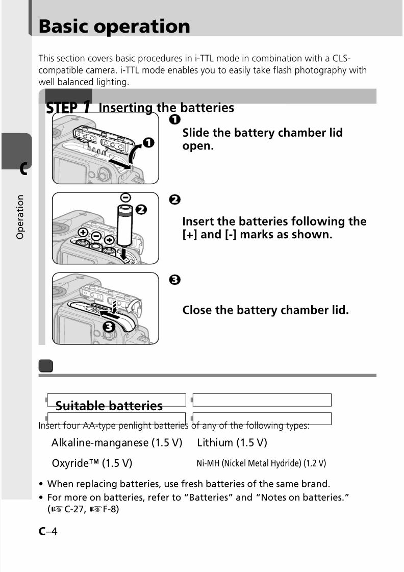
Basic operation
This section covers basic procedures in i-TTL mode in combination with a CLS-
compatible camera. i-TTL mode enables you to easily take flash photography with
well balanced lighting.
Slide the battery chamber lidopen.
Insert the batteries following the[+] and [-] marks as shown.
Close the battery chamber lid.
Inserting the batteriesSTEP 1
Alkaline-manganese (1.5 V) Lithium (1.5 V)
Oxyride™ (1.5 V) Ni-MH (Nickel Metal Hydride) (1.2 V)
Suitable batteries
Insert four AA-type penlight batteries of any of the following types:
When replacing batteries, use fresh batteries of the same brand.
For more on batteries, refer to “Batteries” and “Notes on batteries.”(kC-27,kF-8)
•
•
8/8/2019 SB 900 Manual
http://slidepdf.com/reader/full/sb-900-manual 27/142
C–5
C
O p e r a t i o n
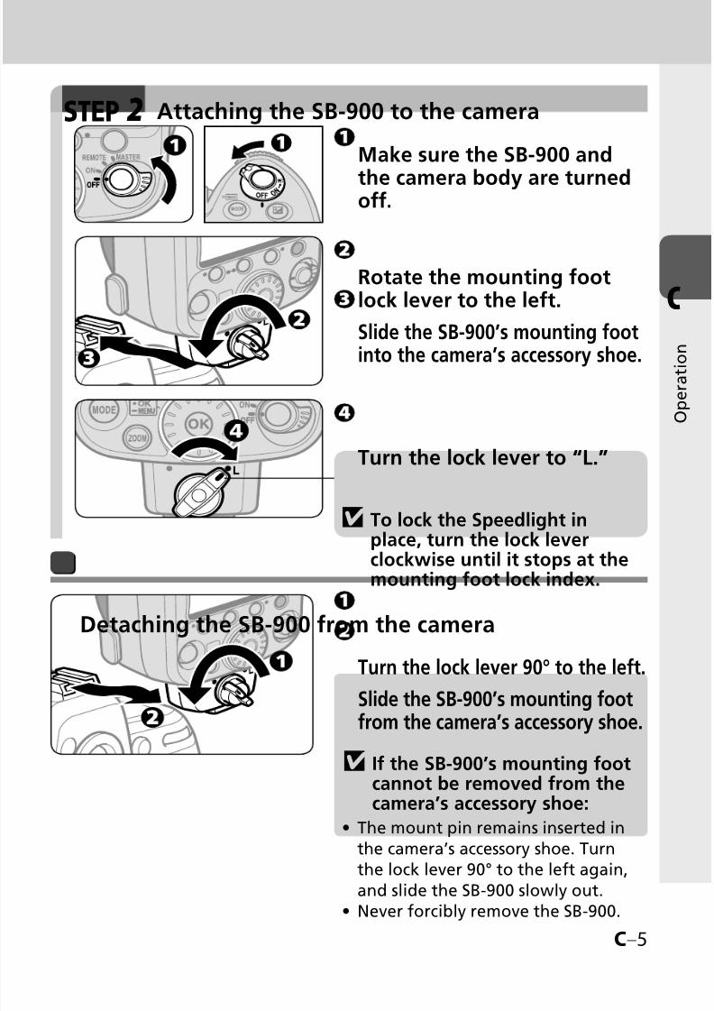
Make sure the SB-900 and
the camera body are turnedoff.
Attaching the SB-900 to the cameraSTEP 2
Rotate the mounting footlock lever to the left.
Slide the SB-900’s mounting foot
into the camera’s accessory shoe.
Turn the lock lever to “L.”
v To lock the Speedlight inplace, turn the lock leverclockwise until it stops at themounting foot lock index.
v If the SB-900’s mounting footcannot be removed from thecamera’s accessory shoe:
The mount pin remains inserted in
the camera’s accessory shoe. Turnthe lock lever 90° to the left again,
and slide the SB-900 slowly out.Never forcibly remove the SB-900.
•
•
Turn the lock lever 90° to the left.
Slide the SB-900’s mounting footfrom the camera’s accessory shoe.
Detaching the SB-900 from the camera

8/8/2019 SB 900 Manual
http://slidepdf.com/reader/full/sb-900-manual 28/142
C–6
C
O p e r a t i o n
Basic operation
Adjusting the flash headSTEP 3
LCD indicator for flash head status
Hold down the flash head
tilting/rotating lock releasebutton to adjust the flashhead to the horizontal/front position.
The flash head is locked at horizontal/
front and 90°.
•
Flash head is set at angle other than
horizontal/front. (Flash head is tilted up or
rotated to the right or left.)
Flash head is set at -7°. (Flash head is
tilted down.)
Flash head is set at horizontal/front.
•
•
•
Turn the SB-900 and thecamera body on.
To turn the SB-900 on, turn the
[Power ON-OFF] switch to [ON].
•
Turning the SB-900 and camera onSTEP 4
Angle of coverage is automatically set
according to lens in use.
•
ISO sensitivity is set automatically.•
When using i-TTL mode
8/8/2019 SB 900 Manual
http://slidepdf.com/reader/full/sb-900-manual 29/142
C–7
C
O p e r a t i o n
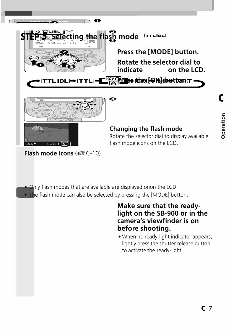
Press the [MODE] button.
Rotate the selector dial toindicate on the LCD.
Press the [OK] button.
Make sure that the ready-light on the SB-900 or in thecamera’s viewfinder is onbefore shooting.
When no ready-light indicator appears,
lightly press the shutter release button
to activate the ready-light.
•
Selecting the flash modeSTEP 5
Changing the flash modeRotate the selector dial to display available
flash mode icons on the LCD.
Flash mode icons (kC-10)
Only flash modes that are available are displayed onon the LCD.
The flash mode can also be selected by pressing the [MODE] button.
•
•
8/8/2019 SB 900 Manual
http://slidepdf.com/reader/full/sb-900-manual 30/142
C–8
C
O p e r a t i o n
Control buttons
1
3
4
5
6
7
8
92
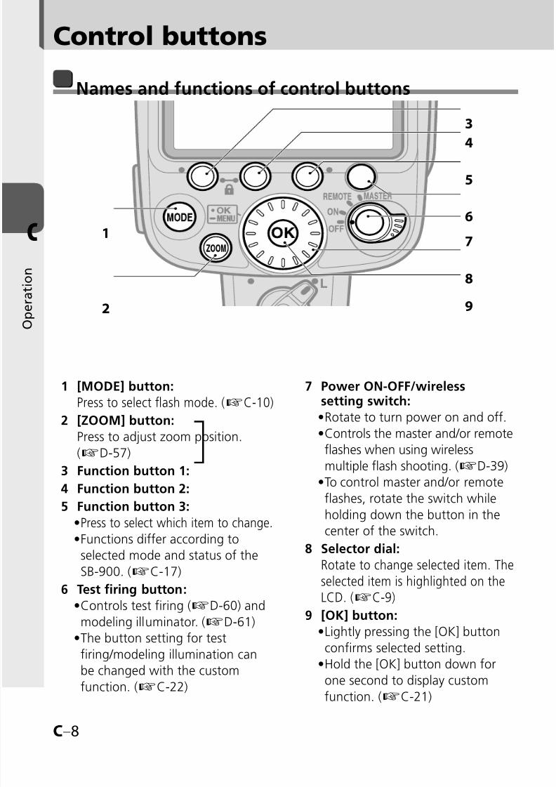
Names and functions of control buttons
1 [MODE] button:
Press to select flash mode. (kC-10)
2 [ZOOM] button:
Press to adjust zoom position.
(kD-57)
3 Function button 1:
4 Function button 2:
5 Function button 3:
Press to select which item to change.Functions differ according to
selected mode and status of theSB-900. (kC-17)
6 Test firing button:
Controls test firing (kD-60) and
modeling illuminator. (kD-61)
The button setting for test
firing/modeling illumination can
be changed with the custom
function. (kC-22)
•
•
•
•
7 Power ON-OFF/wirelesssetting switch:
Rotate to turn power on and off.Controls the master and/or remote
flashes when using wireless
multiple flash shooting. (kD-39)
To control master and/or remote
flashes, rotate the switch while
holding down the button in the
center of the switch.
8 Selector dial: Rotate to change selected item. The
selected item is highlighted on theLCD. (kC-9)
9 [OK] button:
Lightly pressing the [OK] button
confirms selected setting.
Hold the [OK] button down for
one second to display custom
function. (kC-21)
••
•
•
•
8/8/2019 SB 900 Manual
http://slidepdf.com/reader/full/sb-900-manual 31/142
C–9
C
O p e r a t i o n
Control button operation
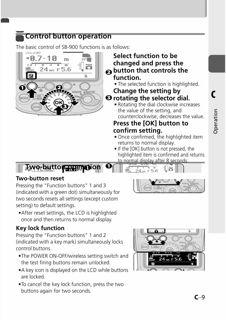
The basic control of SB-900 functions is as follows:
Two-button operation
Select function to bechanged and press thebutton that controls thefunction.
The selected function is highlighted.
Change the setting byrotating the selector dial.
Rotating the dial clockwise increases
the value of the setting, andcounterclockwise, decreases the value.
Press the [OK] button toconfirm setting.
Once confirmed, the highlighted itemreturns to normal display.If the [OK] button is not pressed, thehighlighted item is confirmed and returnsto normal display after 8 seconds.
•
•
•
•
Two-button resetPressing the “Function buttons” 1 and 3
(indicated with a green dot) simultaneously for
two seconds resets all settings (except custom
setting) to default settings.
After reset settings, the LCD is highlighted
once and then returns to normal display.
Key lock functionPressing the “Function buttons” 1 and 2
(indicated with a key mark) simultaneously locks
control buttons.
The POWER ON-OFF/wireless setting switch and
the test firing buttons remain unlocked.
A key icon is displayed on the LCD while buttons
are locked.
To cancel the key lock function, press the two
buttons again for two seconds.
•
•
•
•
8/8/2019 SB 900 Manual
http://slidepdf.com/reader/full/sb-900-manual 32/142
C–10
C
O p e r a t i o n
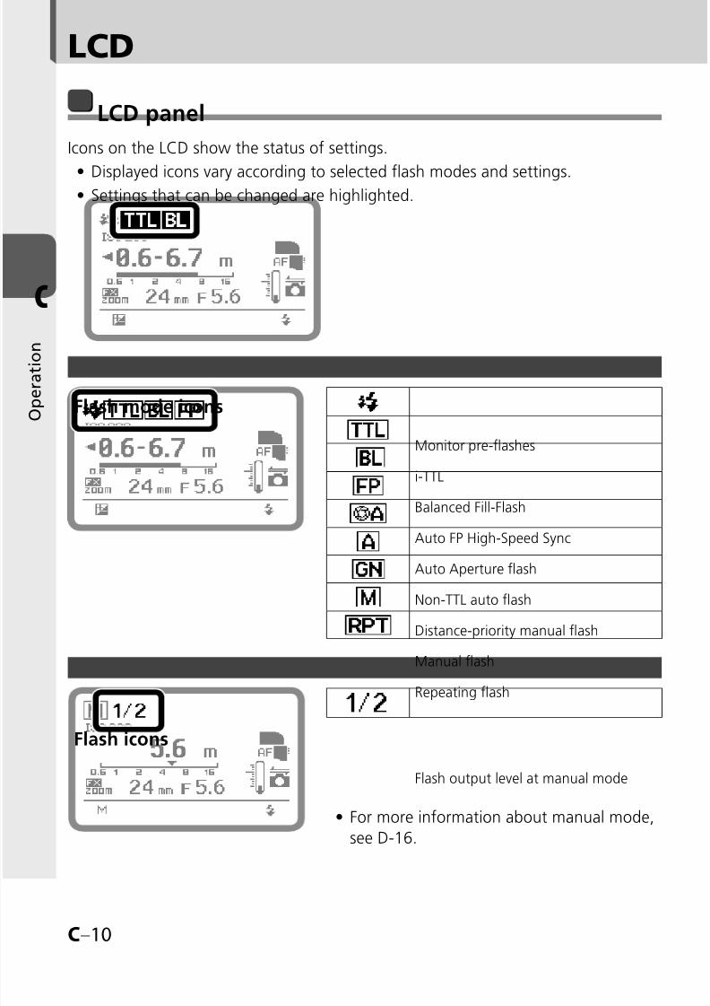
Monitor pre-flashes
i-TTL
Balanced Fill-Flash
Auto FP High-Speed Sync
Auto Aperture flash
Non-TTL auto flash
Distance-priority manual flash
Manual flash
Repeating flash
Flash output level at manual mode
LCD
LCD panel
Icons on the LCD show the status of settings.
Displayed icons vary according to selected flash modes and settings.Settings that can be changed are highlighted.
••
Flash icons
For more information about manual mode,
see D-16.
•
Flash mode icons
8/8/2019 SB 900 Manual
http://slidepdf.com/reader/full/sb-900-manual 33/142
C–11
C
O p e r a t i o n
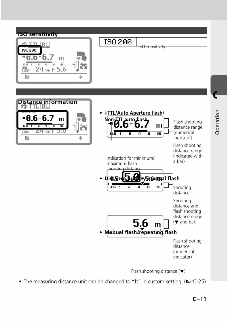
ISO sensitivity
Distance information
ISO sensitivity
Indication for minimum/ maximum flash
shooting distance
i-TTL/Auto Aperture flash/Non-TTL auto flash
•Flash shootingdistance range(numericalindicator)
Flash shootingdistance range(indicated witha bar)
Distance priority manual flash•
Shootingdistance
Shootingdistance andflash shootingdistance range(▼ and bar)
Manual flash/repeating flash•
Flash shootingdistance(numericalindicator)
Flash shooting distance (▼)
The measuring distance unit can be changed to “ft” in custom setting. (kC-25)•

8/8/2019 SB 900 Manual
http://slidepdf.com/reader/full/sb-900-manual 34/142
C–12
C
O p e r a t i o n
LCD
Power zoom
Manual setting of angle of coverage
Power zoom is not possible (manualonly)
Angle of coverage at the maximumwide-angle position
Angle of coverage at the maximumtelephoto position
Angle of coverage with manual settingwhen the built-in wide-flash adapter isnot working
Zoom position
Light distribution for DX-format imagearea with power zoom on
Light distribution for FX-format imagearea with power zoom on
Light distribution for DX-format imagearea when the angle of coverage is
manually setLight distribution for FX-format imagearea when the angle of coverage ismanually set
Light distribution for DX-format imagearea with power zoom offLight distribution for FX-format imagearea with power zoom off
Light distribution angle
t / indication with power zoom onLCD icon varies according to the camera in use.
/ icon appears: D3, D700
icon appears: D300, D60, D40 series
Neither FX nor DX icon appears: Camera not equipped with FX/DX image area
selection
•
•
•
8/8/2019 SB 900 Manual
http://slidepdf.com/reader/full/sb-900-manual 35/142
C–13
C
O p e r a t i o n
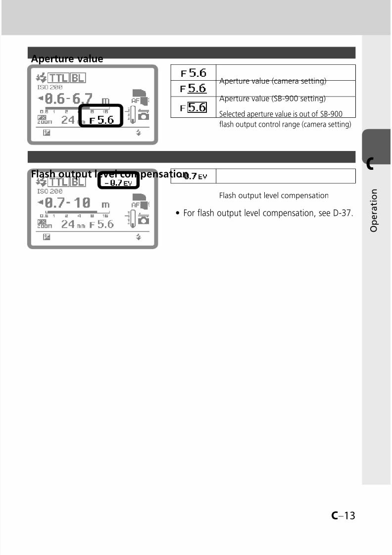
Flash output level compensation
Aperture value (camera setting)
Aperture value (SB-900 setting)
Selected aperture value is out of SB-900
flash output control range (camera setting)
For flash output level compensation, see D-37.•
Flash output level compensation
Aperture value

8/8/2019 SB 900 Manual
http://slidepdf.com/reader/full/sb-900-manual 36/142
C–14
C
O p e r a t i o n
Type of attached color filter
Illumination pattern: Standard
Illumination pattern: Center-weighted
Illumination pattern: Even
Bounce flash operation
Tilt 7° down
Back light is on
AF-assist illumination
Communicating with a CLS compatible camera
Thermal Cut-out on
Thermal Cut-out off
Key lock
Test firing
Modeling illumination
SB-900 condition
Test firing button functions
LCD
8/8/2019 SB 900 Manual
http://slidepdf.com/reader/full/sb-900-manual 37/142
C–15
C
O p e r a t i o n
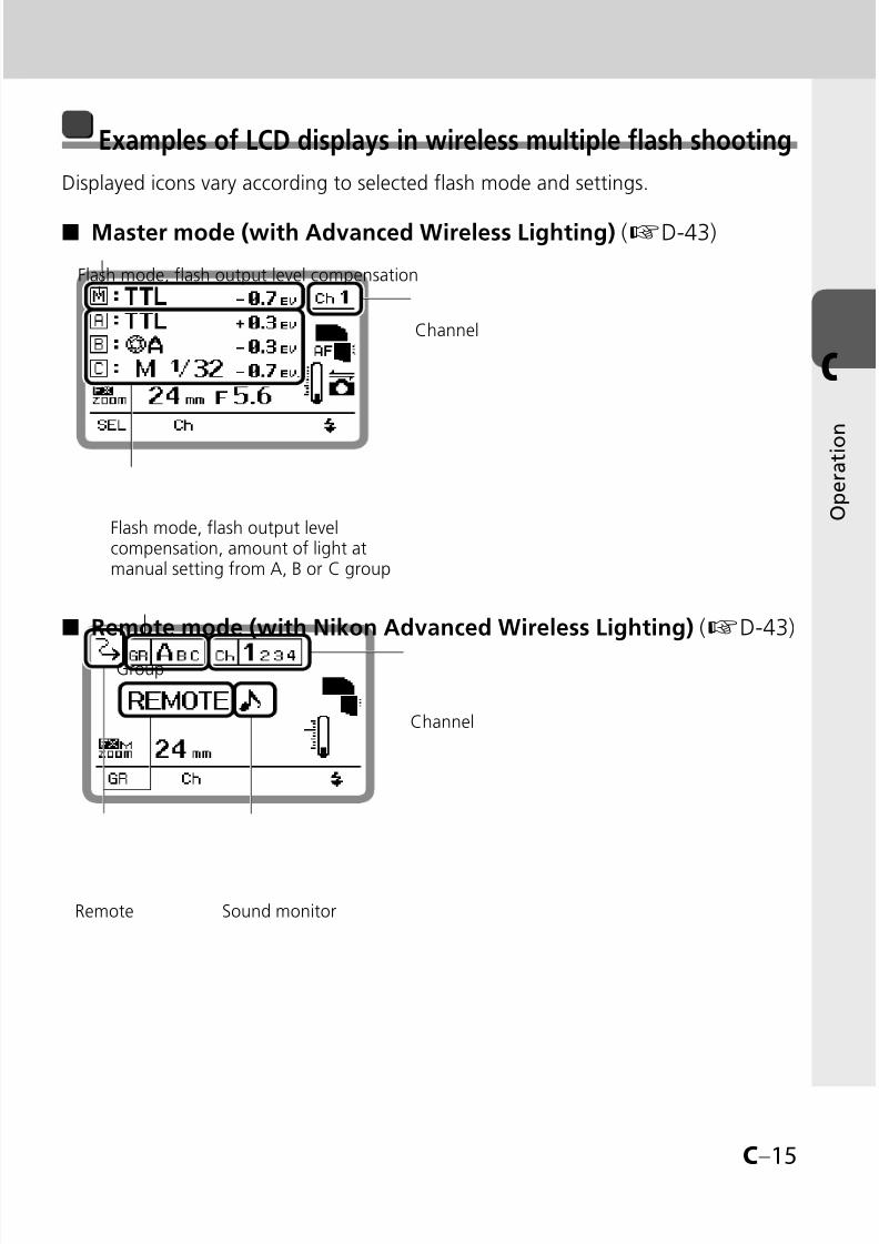
Examples of LCD displays in wireless multiple flash shooting
Displayed icons vary according to selected flash mode and settings.
Master mode (with Advanced Wireless Lighting) (kD-43)■
Channel
Flash mode, flash output levelcompensation, amount of light atmanual setting from A, B or C group
Flash mode, flash output level compensation
Remote mode (with Nikon Advanced Wireless Lighting) (kD-43)■
Channel
Sound monitorRemote
Group

8/8/2019 SB 900 Manual
http://slidepdf.com/reader/full/sb-900-manual 38/142
C–16
C
O p e r a t i o n
Master flash unit at repeating flash (with Nikon AdvancedWireless Lighting) (kD-49)
■
Light amount
Channel
Numberof flashes
Frequency
Master and group A, B or C unit fires (ON)/does not fire (OFF)
Repeating flash
Master mode (with SU-4 type wireless multiple flash shooting)(kD-50)
■
Master mode
Remote mode (with SU-4 type wireless multiple flash shooting)(kD-50)
■
Flash mode
Sound monitor
Remote
LCD
Cancel receiving light from other flash units

8/8/2019 SB 900 Manual
http://slidepdf.com/reader/full/sb-900-manual 39/142
C–17
C
O p e r a t i o n
Functions controlled by Function buttons
Functions controlled by each button vary according to selected mode and settings.
The assigned function for each button is indicated by the following icons.When no function is assigned to a button, no icon appears above the switch on
the LCD.
••
When using a single flash unit■
Flash output level compensation value
Flash output level at manual mode
Aperture
Shooting distance
Value of underexposure at TTL
Number of flashes
Frequency
Power zoom
Change aperture/frequency
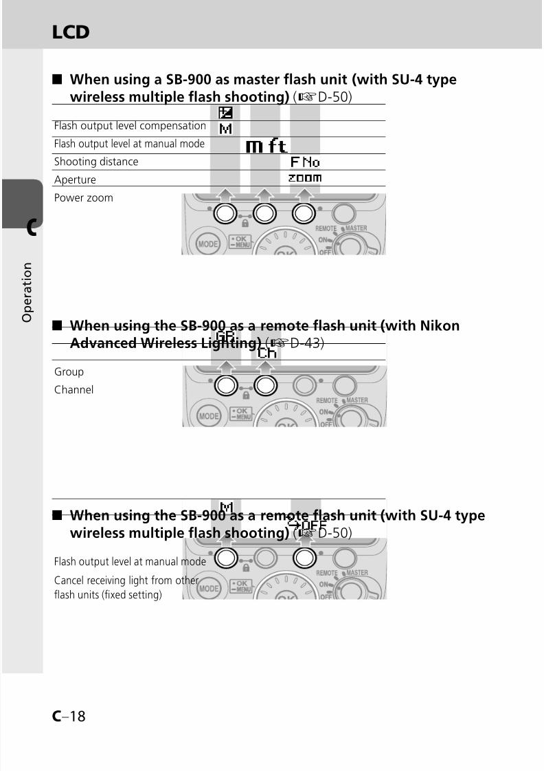
When using a SB-900 as master flash unit (with Nikon AdvancedWireless Lighting) (kD-43)
■
Change the selected group
ChannelFlash output level compensation
Flash output level at manual mode
Aperture
Value of underexposure at TTL
Power zoom
8/8/2019 SB 900 Manual
http://slidepdf.com/reader/full/sb-900-manual 40/142
C–18
C
O p e r a t i o n
When using the SB-900 as a remote flash unit (with NikonAdvanced Wireless Lighting) (kD-43)
■
When using the SB-900 as a remote flash unit (with SU-4 type
wireless multiple flash shooting) (k
D-50)
■
Group
Channel
Flash output level at manual mode
Cancel receiving light from other
flash units (fixed setting)
LCD
When using a SB-900 as master flash unit (with SU-4 typewireless multiple flash shooting) (kD-50)
■
Flash output level compensation
Flash output level at manual mode
Shooting distance
Aperture
Power zoom
8/8/2019 SB 900 Manual
http://slidepdf.com/reader/full/sb-900-manual 41/142
C–19
C
O p e r a t i o n
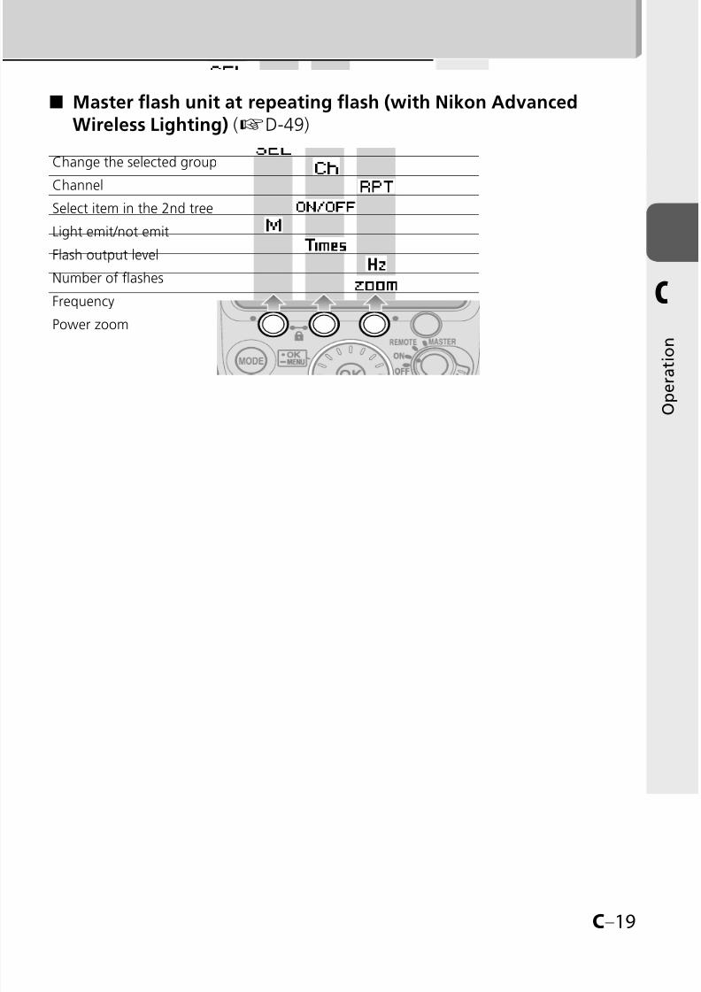
Change the selected group
Channel
Select item in the 2nd tree
Light emit/not emit
Flash output level
Number of flashes
Frequency
Power zoom
Master flash unit at repeating flash (with Nikon AdvancedWireless Lighting) (kD-49)
■

8/8/2019 SB 900 Manual
http://slidepdf.com/reader/full/sb-900-manual 42/142
C–20
C
O p e r a t i o n
Custom functions and settings
Non-TTL auto flash mode (kC-22)
Repeating flash setting of master flash unit (kC-22)
Flash output level at manual mode (kC-22)SU-4 type wireless multiple flash shooting (kC-22)
Illumination pattern (kC-22)
Test firing button (kC-22)
Flash output level of test firing in i-TTL mode (kC-23)
FX/DX selection (kC-23)
Power zoom off (kC-23)
AF-assist illuminator/flash firing off (kC-23)
Standby function (kC-23)
ISO sensitivity (kC-24)
Ready-light setting of remote flash units (kC-24)
LCD panel illuminator (kC-24)
Thermal Cut-out (kC-24)
Sound monitor (kC-24)
LCD panel contrast (kC-25)
Unit of measuring distance (kC-25)
Zoom position setting if the built-in wide-flash adapter is broken (kC-25)
“My menu” setting (kC-25)
Version of firmware (kC-25)
Reset custom setting (kC-25)
Various operations for the SB-900 can be easily set using the LCD.
Displayed icons vary according to the combination of camera and status ofSB-900.
Items that cannot be changed or set are indicated with grid squares.In the “My menu” display, only selected “My menu” items appear on the LCD.
To show all items, select “Full menu.” (kC-25)
•
••
Custom functions and icons

8/8/2019 SB 900 Manual
http://slidepdf.com/reader/full/sb-900-manual 43/142
C–21
C
O p e r a t i o n
Custom setting
Press the [OK] button for approx.
one second to display the customsetting
Rotate the selector dial to choosethe desired custom functions tobe set, and press the [OK] button.
Highlighted item can be set.•
Rotate the selector dial tohighlight the chosen setting, thenpress the [OK] button to set.
Highlighted while setting.Options are displayed.Press the [OK] button to return display foritem selection.
Press the Function button 1 [EXIT] toreturn to the normal display.
The LCD returns to normal display.
•••
•
Available selection
Current setting
Position ofhighlighted item(within 22 items).Not displayed whilean item is being set.
Current settings
Items that cannot be changed or setare indicated with grid squares.

8/8/2019 SB 900 Manual
http://slidepdf.com/reader/full/sb-900-manual 44/142
C–22
C
O p e r a t i o n
Non-TTL auto flash mode (kD-5, D-8)Setting Non-TTL auto flash mode
Auto aperture flash (with modeling illumination)
Auto aperture flash (without modeling illumination)
Non-TTL auto flash (with modeling illumination)
Non-TTL auto flash (without modeling illumination)
Repeating flash setting of master flash unit (kD-49)
The master flash unit’s repeating flash setting for multiple flash shooting
[ON]: Repeating flash on[OFF]: Repeating flash off
Flash output level at manual mode (kD-16)Setting flash output level compensation step between M1/1 and M1/2 in manual mode
[ON ]: Compensation with 1/3 EV step is available
[OFF ]: Compensation with 1 EV step is not available
SU-4 type wireless multiple flash shooting (kD-50)Set SU-4 type wireless multiple flash shooting
[ON]: SU-4 type wireless multiple flash on
[OFF]: SU-4 type wireless multiple flash off
Illumination pattern (kD-24)Select illumination pattern
[CW]: Center-weighted[STD]: Standard
[EVEN]: Even
Test firing button (kD-60, D-61)Select test firing button function
[FLASH]: Test firing
[MODELING]: Modeling illumination
Available Custom functions and settings
(Bold: default)•
Custom functions and settings

8/8/2019 SB 900 Manual
http://slidepdf.com/reader/full/sb-900-manual 45/142
C–23
C
O p e r a t i o n
Flash output level of test firing in i-TTL mode (kD-60)Set flash output level of test firing in i-TTL mode
M1/128: Approx. 1/128
M1/32: Approx. 1/32M1/1: Ful
FX/DX selection (kD-62)Select the light distribution angle in accordance with the camera’simage area between FX- and DX-format.
FX±∞DX: Automatically set according to the camera
FX: Nikon FX format (36 x 24)
DX: Nikon DX format (24 x 16)
Power zoom off (kD-57)
Select Power zoom on/off
ON: Power zoom off (only for manual setting)
OFF: Power zoom on (manual setting is not available)
AF-assist illuminator/flash firing off (kD-58)Set AF-assist illumination on/off and flash on/off
ON: Activate AF-assist illumination
OFF: Cancel AF-assist illumination
AF ONLY: Restrict flash firing (only AF-assist illumination fires)
Standby function (kC-28)
Adjusting the time before the standby function is activatedAUTO: the SB-900 turns off when the camera’s exposure meter turns
off
40: 40 seconds
80: 80 seconds
160: 160 seconds
300: 300 seconds
---: Standby function canceled

8/8/2019 SB 900 Manual
http://slidepdf.com/reader/full/sb-900-manual 46/142
C–24
C
O p e r a t i o n
ISO sensitivity (kD-60)Setting ISO sensitivity. ISO sensitivity range is ISO 3 to 8000.
100: ISO 100
Ready-light setting on remote flash units (kD-42)Select the setting of ready-light on remote flash unit/s in multipleflash shooting for low battery power consumption.
REAR, FRONT: Front (at remote setting) and rear ready-lights on
REAR: Rear ready-light on
FRONT: Front ready-light on (at remote setting)
LCD panel illuminator (kF-9)Setting the LCD panel illuminator to turn on or off
ON: Turn on
OFF: Turn off
Thermal Cut-out (kF-6)Setting the Thermal Cut-out function on or off
ON: Thermal Cut-out on
OFF: Thermal Cut-out off
Sound monitor (kD-42, F-6)When the SB-900 is used as a wireless remote flash unit, or theoverheat detection is on, the sound monitor function can beactivated or cancelled.
ON: Sound on
OFF: Sound off
Custom functions and settings

8/8/2019 SB 900 Manual
http://slidepdf.com/reader/full/sb-900-manual 47/142
C–25
C
O p e r a t i o n
LCD panel contrast (kF-9)Adjust the brightness of the LCD panel. Contrast levels aredisplayed on the LCD in a nine-step graph.
5 levels in 9 steps
Unit of measuring distanceSet the unit of measuring distance
m: meters
ft.: feet
Zoom position setting if the built-in wide-flash adapter isbroken (kF-4)Select whether the zoom position is manually set or fixed if thebuilt-in wide flash adapter is broken.
ON: Available
OFF: Not available
“My menu” setting (kC-26)Select items displayed on the LCD in custom setting.
FULL: Display all items
MY MENU: Display items only selected as “My menu”
SET UP: Set up the “My menu” items
Version of firmware (kF-10)
Show firmware version.
Reset custom settingReset custom setting except unit of measuring distance and “Mymenu” items to default setting.
YES: Reset to default
NO: Do not reset

8/8/2019 SB 900 Manual
http://slidepdf.com/reader/full/sb-900-manual 48/142
C–26
C
O p e r a t i o n
My menu
When frequently used custom setting items are set as “My menu,” only the
selected items are displayed on the LCD in the custom setting.“My menu” items can be changed at any time.
To display all items, select “Full.”
•
•
How to set “My menu”
Select “SET UP” in “Mymenu,” and press the
[OK] button.Select items to be set as “Mymenu” items, and press the[OK] button.
Pressing the [OK] button displays in
the check box of the selected item.
For items that cannot be selected, no
check box appears.
To cancel the mark, press the [OK]button again.
Repeat Step to select alldesired items, then pressFunction button 1 [BACK] toreturn to set-up mode.
Press [EXIT] to exit customsetting.
The LCD returns to normal display.
•
•
•
•
Custom functions and settings

8/8/2019 SB 900 Manual
http://slidepdf.com/reader/full/sb-900-manual 49/142

8/8/2019 SB 900 Manual
http://slidepdf.com/reader/full/sb-900-manual 50/142
C–28
C
O p e r a t i o n
Standby function to conserve battery power
To cancel Standby
Turn the [Power ON-OFF/wireless setting] switch to [ON], [REMOTE] or [MASTER].
Press the [Test firing] button.
Press the camera’s shutter release button halfway.
Adjusting the lead time before the Standby function is activated
The lead time before the Standby function is activated can be adjusted by
custom setting (kC-23).
•
•
•
•
If the SB-900 and the camera are not used for
more than a specified time, the Standby function isautomatically activated to conserve battery power.
The Standby function activates when the camera’sexposure meter is turned off (default setting).
•
Batteries
8/8/2019 SB 900 Manual
http://slidepdf.com/reader/full/sb-900-manual 51/142
D–1
D
F l a s h m o d e s a
n d f u n c t i o n s
D–1
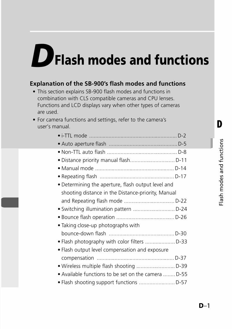
DExplanation of the SB-900’s flash modes and functions
This section explains SB-900 flash modes and functions in
combination with CLS compatible cameras and CPU lenses.
Functions and LCD displays vary when other types of cameras
are used.
For camera functions and settings, refer to the camera’s
user’s manual.
•
•
Flash modes and functions
i-TTL mode ........................................................... D-2
Auto aperture flash ..............................................D-5
Non-TTL auto flash ............................................... D-8
Distance priority manual flash.............................. D-11
Manual mode ..................................................... D-14
Repeating flash .................................................. D-17
Determining the aperture, flash output level and
shooting distance in the Distance-priority, Manual
and Repeating flash mode .................................. D-22
Switching illumination pattern ............................ D-24
Bounce flash operation ....................................... D-26
Taking close-up photographs with
bounce-down flash ............................................ D-30
Flash photography with color filters .................... D-33
Flash output level compensation and exposure
compensation .................................................... D-37
Wireless multiple flash shooting .......................... D-39
Available functions to be set on the camera ........ D-55
Flash shooting support functions ........................ D-57
•
•
•
•
•
•
•
•
•
•
•
•
•
•
•
8/8/2019 SB 900 Manual
http://slidepdf.com/reader/full/sb-900-manual 52/142
D–2
D
F l a s h m o d e s a
n d f u n c t i o n s
i-TTL mode
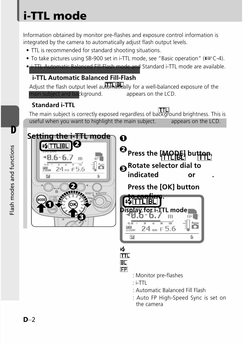
: Monitor pre-flashes
: i-TTL
: Automatic Balanced Fill Flash
: Auto FP High-Speed Sync is set onthe camera
Information obtained by monitor pre-flashes and exposure control information is
integrated by the camera to automatically adjust flash output levels.
TTL is recommended for standard shooting situations.
To take pictures using SB-900 set in i-TTL mode, see “Basic operation” (kC-4).i-TTL Automatic Balanced Fill-Flash mode and Standard i-TTL mode are available.
i-TTL Automatic Balanced Fill-Flash
Adjust the flash output level automatically for a well-balanced exposure of the
main subject and background. appears on the LCD.
Standard i-TTL
The main subject is correctly exposed regardless of background brightness. This is
useful when you want to highlight the main subject. appears on the LCD.
•
••
Setting the i-TTL mode
Press the [MODE] button.
Rotate selector dial to
indicated or .
Press the [OK] button
to confirm.
Display for i-TTL mode

8/8/2019 SB 900 Manual
http://slidepdf.com/reader/full/sb-900-manual 53/142
D–3
D
F l a s h m o d e s a
n d f u n c t i o n s
tMonitor pre-flashes
In i-TTL mode, immediately before the flash fires, the SB-900 fires a series of
imperceptible pre-flashes to analyze the information of the subject.
•
SB-900 flash shooting distance range
The flash shooting distance range is
indicated by numbers and a bar chart
on the LCD.
Set the shooting distance within this range.
The range varies depending on ISO
sensitivity, camera's image area
setting, illumination pattern, angleof coverage and aperture. For more
information, see “Specifications.”
(kF-16)
•
•
t Auto setting of ISO sensitivity, aperture and focal length
When using with a CLS-compatible camera and a CPU lens, SB-900's ISO sensitivity,
aperture and focal length are automatically set according to camera setting.
For more information about the ISO sensitivity range, see the camera’s
user’s manual.
•

8/8/2019 SB 900 Manual
http://slidepdf.com/reader/full/sb-900-manual 54/142
D–4
D
F l a s h m o d e s a
n d f u n c t i o n s
i-TTL mode
vWhen insufficient light for correct exposure is indicated
When the SB-900 fires at full flash
output level, ready-lights on theSB-900 and in the camera’sviewfinder blink for approx. threeseconds after shooting.
In this case, underexposure mayoccur. To compensate the exposure,use a wider aperture or move closerto the subject and reshoot.
The underexposure value (-0.3 to-3.0 EV) is displayed on the SB-900’sLCD panel for approx. three secondswhile the above ready-lights blink.
Pressing Function button 2 recallsdisplay of underexposure value inTTL mode.
•
•
•
•
t Changing camera’s metering mode
When camera's metering mode is changed to spot metering while i-TTL
Automatic Balanced Fill-Flash is selected, the TTL mode automatically changes to
the standard i-TTL mode.
In such case, the TTL mode automatically changes to the i-TTL AutomaticBalanced Fill-Flash, after changing camera's metering mode to Multi-pattern orCenter-weighted.
•
•
8/8/2019 SB 900 Manual
http://slidepdf.com/reader/full/sb-900-manual 55/142
D–5
D
F l a s h m o d e s a
n d f u n c t i o n s
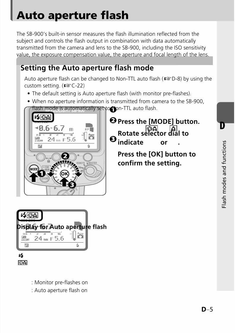
: Monitor pre-flashes on
: Auto aperture flash on
Auto aperture flash
The SB-900’s built-in sensor measures the flash illumination reflected from the
subject and controls the flash output in combination with data automatically
transmitted from the camera and lens to the SB-900, including the ISO sensitivity
value, the exposure compensation value, the aperture and focal length of the lens.
Auto aperture flash can be changed to Non-TTL auto flash (kD-8) by using the
custom setting. (kC-22)
The default setting is Auto aperture flash (with monitor pre-flashes).
When no aperture information is transmitted from camera to the SB-900,
flash mode is automatically set to Non-TTL auto flash.
•
•
Setting the Auto aperture flash mode
Press the [MODE] button.
Rotate selector dial to
indicate or .
Press the [OK] button to
confirm the setting.
Display for Auto aperture flash

8/8/2019 SB 900 Manual
http://slidepdf.com/reader/full/sb-900-manual 56/142
D–6
D
F l a s h m o d e s a
n d f u n c t i o n s
Auto aperture flash
The flash shooting distance range is indicated by
numbers and a bar chart in the LCD.
Set the shooting distance within this range.
The range varies depending on ISO sensitivity,
camera’s image area setting, illumination pattern,
angle of coverage and aperture. For more
information, see “Specifications.” (kF-16)
•
•
Flash shooting distance range in Auto aperture flash mode
v Notes on using a telephoto lens in the Auto aperture flash modeWhen shooting a distant subject using a telephoto lens in “Auto
aperture flash” mode, underexposure may occur even though thesubject is within the flash shooting distance range.Use of the i-TTL mode is recommended.
•
•
tMonitor pre-flashes
Monitor pre-flashes on or off can be set by using the custom setting. (kC-22)
The SB-900 fires a series of imperceptible monitor pre-flashes immediately
before the flash fires to obtain information on the subject.
To perform the Auto FP-High Speed Sync (kD-55) or FV Lock (kD-55),
activate the monitor pre-flashes.
•
•
•

8/8/2019 SB 900 Manual
http://slidepdf.com/reader/full/sb-900-manual 57/142
D–7
D
F l a s h m o d e s a
n d f u n c t i o n s
Taking a picture in Auto aperture flash mode
SHOOT
CUSTOM
tWhile using a CPU lens which has anaperture ring
While using a CPU lens which has an aperture ring,
lock the lens aperture at minimum. For details, see
lens’ user’s manual.
Camera’s control panel
Camera’s control panel
Set the camera’s exposure mode to “P”
(Programmed Auto) or “A” (Aperture-Priority Auto).
With the camera’s exposure mode setto “A”, set the aperture on the camera
while reading the flash shooting
distance range on the SB-900’s LCD.Decide the aperture value by referring to the chart.
Compose the picture, confirm that theready-light is on, then shoot.
•
v Insufficient light for correct exposure
When the SB-900 fires at full flash output level, ready-
lights on the SB-900 and in the camera’s viewfinder
blink for approx. three seconds after shooting.
In this case, underexposure may occur. To
compensate the exposure, use a wider aperture or
move closer to the subject and reshoot.
•
•
t Checking the correct exposure before shooting
Confirm the test firing indicator appears on the LCD.
Make the necessary settings on the SB-900 and
camera and press the test firing button to fire
the flash.
Ready-lights blinking after shooting may indicate
insufficient light for correct exposure. In this case,
set a wider aperture on the camera or lens, or movecloser to the subject.
•
8/8/2019 SB 900 Manual
http://slidepdf.com/reader/full/sb-900-manual 58/142
D–8
D
F l a s h m o d e s a
n d f u n c t i o n s
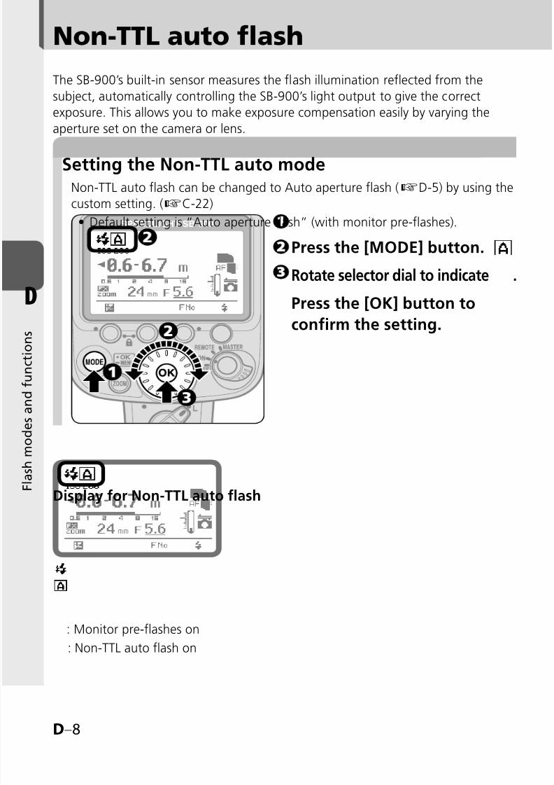
Non-TTL auto flash
Setting the Non-TTL auto mode
The SB-900’s built-in sensor measures the flash illumination reflected from the
subject, automatically controlling the SB-900’s light output to give the correct
exposure. This allows you to make exposure compensation easily by varying the
aperture set on the camera or lens.
Non-TTL auto flash can be changed to Auto aperture flash (kD-5) by using the
custom setting. (kC-22)
Default setting is “Auto aperture flash” (with monitor pre-flashes).•
Press the [MODE] button.
Rotate selector dial to indicate .
Press the [OK] button to
confirm the setting.
Display for Non-TTL auto flash
: Monitor pre-flashes on
: Non-TTL auto flash on

8/8/2019 SB 900 Manual
http://slidepdf.com/reader/full/sb-900-manual 59/142
D–9
D
F l a s h m o d e s a
n d f u n c t i o n s
tMonitor pre-flashes
Monitor pre-flashes on or off can be set by using the custom setting. (kC-22)
When the monitor pre-flashes are activated, the SB-900 fires a series of
imperceptible monitor pre-flashes immediately before the flash fires to obtaininformation on the subject.
To perform the Auto FP-High Speed Sync (kD-55) or FV Lock (kD-55),
activate the monitor pre-flashes.
•
•
•
The flash shooting distance range is indicated by
numbers and a bar chart on the LCD.Set the shooting distance within this range.
The range varies depending on ISO sensitivity,
camera’s image area setting, illumination pattern,
angle of coverage and aperture. For more
information, see “Specifications.” (kF-16)
•
•
Flash shooting distance range in Non-TTL auto flash mode
vWhen using a telephoto lens in the Non-TTL auto flash mode
When shooting using a telephoto lens in Non-TTL auto flash mode,underexposure may occur even though the subject is within flash
shooting distance range.Use of the i-TTL mode is recommended.
•
•

8/8/2019 SB 900 Manual
http://slidepdf.com/reader/full/sb-900-manual 60/142
D–10
D
F l a s h m o d e s a
n d f u n c t i o n s
Non-TTL auto flash
Taking a picture in Non-TTL auto flash mode
Camera’s control panel
t Checking the correct exposure before shooting
Set the camera’s exposure mode
to “A” (Aperture-Priority Auto)or “M” (Manual).
Press the Function button 3.
Set the aperture by rotating theselector dial while reading theflash shooting distance range onthe SB-900’s LCD.
Press the [OK] button.Set the aperture value decidedin step 3 on the camera or lens.
Set the camera to its highestflash sync shutter speed.
Compose the picture, confirmthat the ready-light is on,then shoot.
v Insufficient light for correct exposureWhen the SB-900 fires at full flash outputlevel, ready-lights on the SB-900 and in the
camera’s viewfinder blink for approx. threeseconds after shooting.
In this case, underexposure may occur. To
compensate the exposure, use a wider apertureor move closer to the subject and reshoot.
•
•
Confirm the test firing indicator appears on the LCD.
Make the necessary settings on the SB-900 and camera
and press the test firing button to fire the flash.
Ready-lights blinking after shooting may indicate
insufficient light for correct exposure. In this case, set awider aperture on the camera or lens, or move closer to
the subject.
•

8/8/2019 SB 900 Manual
http://slidepdf.com/reader/full/sb-900-manual 61/142
D–11
D
F l a s h m o d e s a
n d f u n c t i o n s
Distance priority manual flash
Setting the Distance-priority manual flash
In this flash mode, when you enter the shooting distance value, the SB-900automatically controls the light output according to the aperture set. You can takepictures that have the same exposure even when shooting at different apertures.
Flash output level is automatically compensated by changing the flash outputlevel compensation value.
Underexposure is not indicated in Distance-priority manual flash mode.
•
•
Distance-priority manual flash is not available when the SB-900’s flash head is
adjusted to other than the horizontal/front or bounce-down flash position.
Press the [MODE] button. Rotate selector dial to indicate .
Press [OK] button to confirm
the setting.
Display for Distance-priority manual flash (at 5 m shooting distance)
Shooting distance (numerical indicator)
Shooting distance and flash shooting distance range (▼ and bar)
When (▼) appears on the shooting distance range indication (bar),the SB-900 fires with appropriate flash output.

8/8/2019 SB 900 Manual
http://slidepdf.com/reader/full/sb-900-manual 62/142
D–12
D
F l a s h m o d e s a
n d f u n c t i o n s
Distance priority manual flash
Shooting in Distance priority manual flash mode
Set the camera’s exposure
mode to “A” (Aperture-PriorityAuto) or “M” (Manual).
Press the Function button 2.
Set the shooting distance by
rotating the selector dial. The shooting distance varies depending
on ISO sensitivity within a range between
0.3 m and 20 m.
Press the [OK] button.
Set the aperture on the camera.Aperture should be calculated using the
calculation formula. (kD-22)
The aperture on the SB-900 cannot be set
directly.
Compose the picture, confirmthat the ready-light is on,then shoot.
•
•
•
Camera’s control panel
See charts for flash shooting distance range.
If the desired shooting distance is not on the chart, select a shorter shooting
distance (e.g. when your desired shooting distance is 2.7 m, select 2.5 m.).
•
•
Flash shooting distance range in “Distance-priority manual flash” mode
0.3 0.4 0.5 0.6 0.7 0.8 0.9 1.0 1.1 1.3 1.4 1.6
1.8 2.0 2.2 2.5 2.8 3.2 3.6 4.0 4.5 5.0 5.6 6.3
7.1 8.0 9.0 10 11 13 14 16 18 20

8/8/2019 SB 900 Manual
http://slidepdf.com/reader/full/sb-900-manual 63/142
D–13
D
F l a s h m o d e s a
n d f u n c t i o n s
t When the flash head is rotated in Distance-priority manual flash mode
When the flash head is rotated to other than the horizontal/front or bounce-
down flash position in Distance-priority manual flash, the flash mode is
automatically changed to Auto aperture flash mode or Non-TTL auto flashmode.
In this case, when the flash head is adjusted to horizontal/front or bounce-down
flash position again, the flash mode is automatically changed to Distance-priority
manual flash mode.
•
•
v Insufficient light for correct exposure
When the SB-900 fires at full flash output level,ready-lights on the SB-900 and in the camera’s
viewfinder blink for approximately three
seconds after shooting.In this case, underexposure may occur. To
compensate, use a wider aperture or movecloser to the subject and reshoot.
•
•
8/8/2019 SB 900 Manual
http://slidepdf.com/reader/full/sb-900-manual 64/142
D–14
D
F l a s h m o d e s a
n d f u n c t i o n s
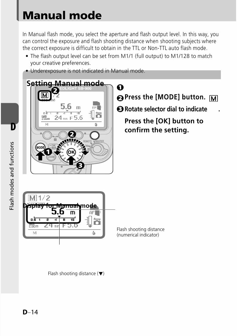
Manual mode
Setting Manual mode
In Manual flash mode, you select the aperture and flash output level. In this way, youcan control the exposure and flash shooting distance when shooting subjects wherethe correct exposure is difficult to obtain in the TTL or Non-TTL auto flash mode.
The flash output level can be set from M1/1 (full output) to M1/128 to matchyour creative preferences.
Underexposure is not indicated in Manual mode.
•
•
Press the [MODE] button.
Rotate selector dial to indicate .
Press the [OK] button to
confirm the setting.
Display for Manual mode
Flash shooting distance
(numerical indicator)
Flash shooting distance (▼)
8/8/2019 SB 900 Manual
http://slidepdf.com/reader/full/sb-900-manual 65/142
D–15
D
F l a s h m o d e s a
n d f u n c t i o n s
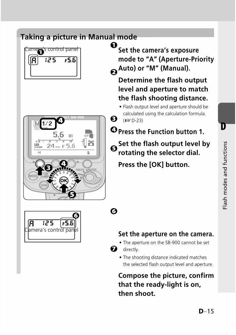
Taking a picture in Manual mode
Set the camera’s exposure
mode to “A” (Aperture-PriorityAuto) or “M” (Manual).
Determine the flash output
level and aperture to match
the flash shooting distance.Flash output level and aperture should be
calculated using the calculation formula.
(kD-23)
Press the Function button 1.
Set the flash output level by
rotating the selector dial.
Press the [OK] button.
•
Camera’s control panel
Camera’s control panel
Set the aperture on the camera.The aperture on the SB-900 cannot be set
directly.
The shooting distance indicated matches
the selected flash output level and aperture.
Compose the picture, confirm
that the ready-light is on,
then shoot.
•
•
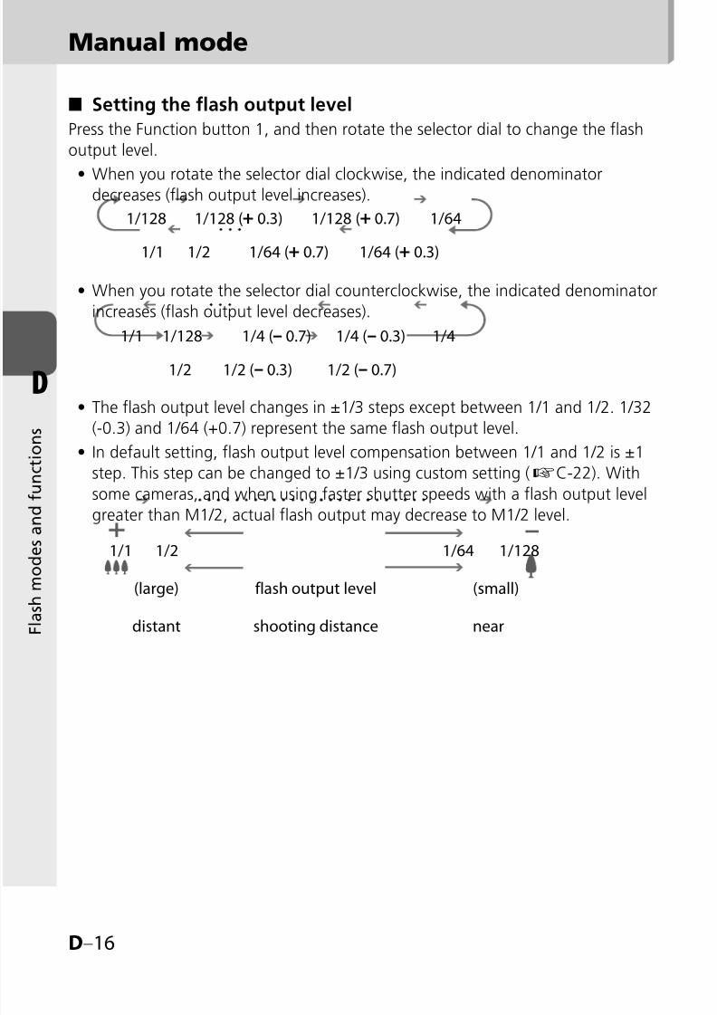
8/8/2019 SB 900 Manual
http://slidepdf.com/reader/full/sb-900-manual 66/142
D–16
D
F l a s h m o d e s a
n d f u n c t i o n s
Setting the flash output level
Press the Function button 1, and then rotate the selector dial to change the flash
output level.
When you rotate the selector dial clockwise, the indicated denominatordecreases (flash output level increases).
When you rotate the selector dial counterclockwise, the indicated denominator
increases (flash output level decreases).
The flash output level changes in ±1/3 steps except between 1/1 and 1/2. 1/32
(-0.3) and 1/64 (+0.7) represent the same flash output level.
In default setting, flash output level compensation between 1/1 and 1/2 is ±1
step. This step can be changed to ±1/3 using custom setting (kC-22). With
some cameras, and when using faster shutter speeds with a flash output level
greater than M1/2, actual flash output may decrease to M1/2 level.
■
•
•
•
•
Manual mode
1/128 1/128 (+ 0.3) 1/128 (+ 0.7) 1/64
1/1 1/2 1/64 (+ 0.7) 1/64 (+ 0.3)
1/1 1/128 1/4 (– 0.7) 1/4 (– 0.3) 1/4
1/2 1/2 (– 0.3) 1/2 (– 0.7)
1/1 1/2 1/64 1/128
(large) flash output level (small)
distant shooting distance near

8/8/2019 SB 900 Manual
http://slidepdf.com/reader/full/sb-900-manual 67/142
D–17
D
F l a s h m o d e s a
n d f u n c t i o n s
Repeating flash
Setting the Repeating flash
In Repeating flash mode, the SB-900 fires repeatedly during a single exposure,
creating stroboscopic multiple-exposure effects. This operation is useful when
shooting fast-moving subjects.
Be sure to use fresh or fully charged batteries and allow enough time for theflash to recycle between each repeating flash session.
Use of a tripod is recommended to prevent camera/flash shake, because slower
shutter speeds are used.
Underexposure is not indicated in Repeating flash mode.
•
•
•
Press the [MODE] button.
Rotate selector dial to
indicate .
Press the [OK] button to
confirm the setting.
Display for Repeating flash
Flash shooting distance(numerical indication)
Number offlashes
Flash shooting distance (▼)
Frequency
Flash output level

8/8/2019 SB 900 Manual
http://slidepdf.com/reader/full/sb-900-manual 68/142
D–18
D
F l a s h m o d e s a
n d f u n c t i o n s
Repeating flash
Frequency
Flash output level
M1/8M1/8–
1/3EV
M1/8–
2/3EVM1/16
M1/16–
1/3EV
M1/16–
2/3EVM1/32
M1/32–
1/3EV
M1/32–
2/3EVM1/64
M1/64–
1/3EV
M1/64–
2/3EVM1/128
1Hz14 16 22 30 36 46 60 68 78 90 90 90 90
2Hz
3Hz 12 14 18 30 36 46 60 68 78 90 90 90 90
4Hz 10 12 14 20 24 30 50 56 64 80 80 80 80
5Hz 8 10 12 20 24 30 40 44 52 70 70 70 70
6Hz 6 7 10 20 24 30 32 36 40 56 56 56 56
7Hz 6 7 10 20 24 26 28 32 36 44 44 44 44
8Hz 5 6 8 10 12 14 24 26 30 36 36 36 36
9Hz 5 6 8 10 12 14 22 24 28 32 32 32 32
10Hz 4 5 6 8 9 10 20 22 26 28 28 28 28
20Hz
4 5 6 8 9 10 12 14 18 24 24 24 24
30Hz
40Hz
50Hz
60Hz
70Hz80Hz
90Hz
100Hz
Setting the flash output level, the number of repeating flashes,and the frequency (Hz) per frame
The number of flashes (Times) represents the number of times the flash fires
per frame.The frequency (Hz) represents the number of times the flash fires per second.
The number of flashes is the maximum flash firing number. Because the
Speedlight fires during a single exposure, the actual number of repeating flashes
per frame falls below the one set as the shutter speed increases or the number
of flashes per second decreases.
Referring to the table below, set the flash output level, the frequency, and the
number of repeating flashes separately for each picture.
■
•
•
•
•
Maximum number of repeating flashes per frame

8/8/2019 SB 900 Manual
http://slidepdf.com/reader/full/sb-900-manual 69/142
D–19
D
F l a s h m o d e s a
n d f u n c t i o n s
Shooting with Repeating flash
Set the camera’s exposure mode
to “M” (Manual).Press the Function button 1,rotate the selector dial to setflash output level, and press the[OK] button to confirm.
Available flash output level is 1/8 – 1/128.
Press the Function button 2,
rotate the selector dial to setnumber of flashes, and press the[OK] button to confirm.
Press the Function button 3,rotate the selector dial to setfrequency, and press the [OK]button to confirm.
Determine the guide numberaccording to the set flash outputlevel and focal length, thencalculate the correct aperturefrom the guide number andshooting distance. Finally, setthis aperture on the camera.
The guide number and aperture should be
calculated using the calculation formula.
(kD-22)
The aperture on the SB-900 cannot be set
directly.
The shooting distance indicated matches
the selected flash output level and aperture.
•
•
•
•
Camera’s control panel
Camera’s control panel
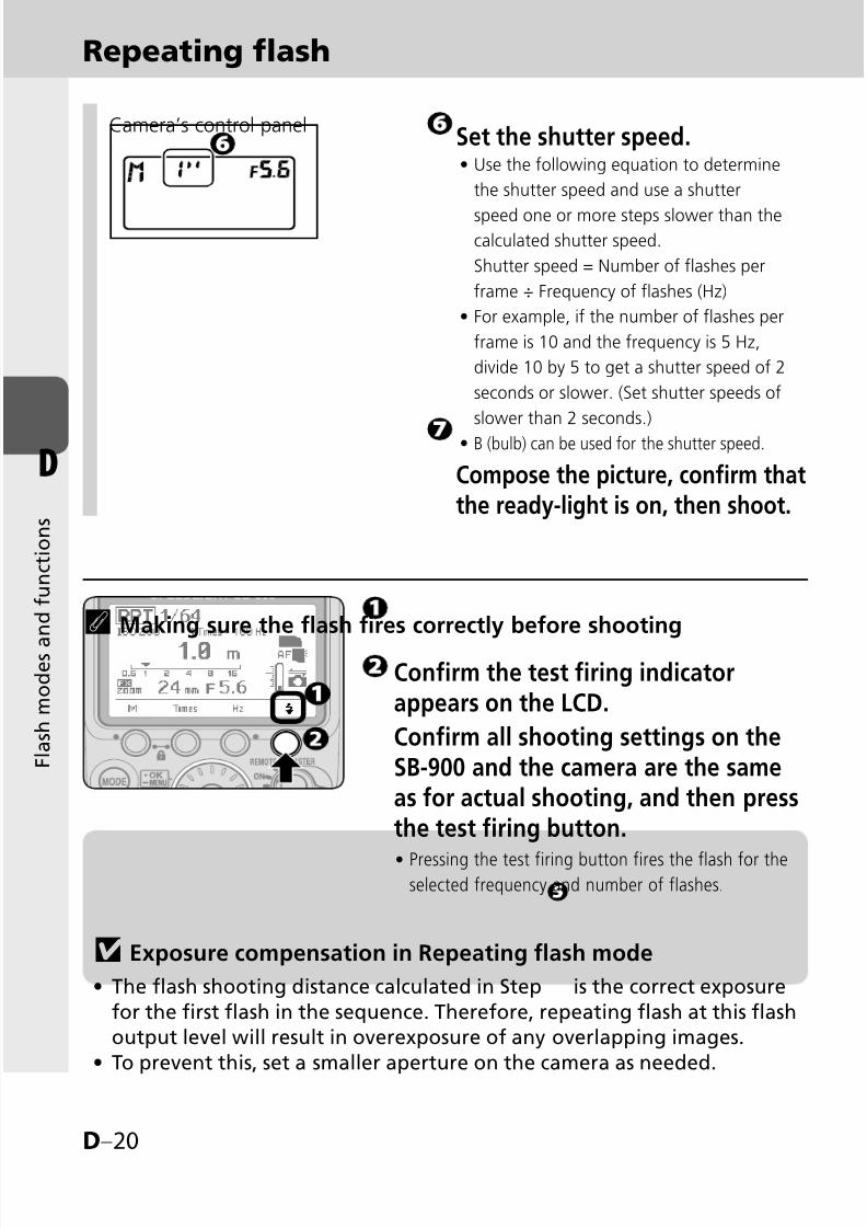
8/8/2019 SB 900 Manual
http://slidepdf.com/reader/full/sb-900-manual 70/142
D–20
D
F l a s h m o d e s a
n d f u n c t i o n s
Repeating flash
Set the shutter speed.Use the following equation to determine
the shutter speed and use a shutter
speed one or more steps slower than thecalculated shutter speed.
Shutter speed = Number of flashes per
frame ÷ Frequency of flashes (Hz)
For example, if the number of flashes per
frame is 10 and the frequency is 5 Hz,
divide 10 by 5 to get a shutter speed of 2
seconds or slower. (Set shutter speeds of
slower than 2 seconds.)
B (bulb) can be used for the shutter speed.
Compose the picture, confirm thatthe ready-light is on, then shoot.
•
•
•
Camera’s control panel
v Exposure compensation in Repeating flash mode
The flash shooting distance calculated in Step is the correct exposure
for the first flash in the sequence. Therefore, repeating flash at this flashoutput level will result in overexposure of any overlapping images.
To prevent this, set a smaller aperture on the camera as needed.
•
•
tMaking sure the flash fires correctly before shooting
Confirm the test firing indicatorappears on the LCD.
Confirm all shooting settings on theSB-900 and the camera are the sameas for actual shooting, and then pressthe test firing button.
Pressing the test firing button fires the flash for theselected frequency and number of flashes.
•
8/8/2019 SB 900 Manual
http://slidepdf.com/reader/full/sb-900-manual 71/142
D–21
D
F l a s h m o d e s a
n d f u n c t i o n s
tWhen the aperture value is not displayed in the SB-900's LCD
Camera’s aperture data is not transmitted to the SB-900.
Press the Function button 3 for one second to highlight f-number and set
appropriate aperture value on the SB-900.
•
•

8/8/2019 SB 900 Manual
http://slidepdf.com/reader/full/sb-900-manual 72/142
D–22
D
F l a s h m o d e s a
n d f u n c t i o n s
Determining the aperture, flash output level and shooting distance
ISO 25 50 100 200 400 800 1600 3200 6400
Factors 0.5 0.71 1 1.4 2 2.8 4 5.6 8
In Distance-priority, Manual and Repeating flash modes, use the guide number
table and the following equation to calculate the aperture, flash output level, and
shooting distance to obtain the correct exposure.
The guide number (GN at ISO 100; m/ft) indicates the amount of light generatedby the flash.
The larger the number, the greater the flash output.
•
•
The table below shows the guide numbers while using the standard illumination
pattern when the SB-900 is mounted on a Nikon FX format camera.
For others, see “Specifications” (kF-18).•
BA: With the Nikon Diffusion Dome attached
WP: With the wide-flash adapter in place
•
•
Guide number (GN at ISO 100; m/ft)
ISO sensitivity factorsFor sensitivities, multiply the guide number by the factors shown in the table below.
Flashoutputlevel
Zoom position (mm)
14mm17 18 20 24 28 35 50 70 85 105 120 135 180 200WP +
BA BA WP
1/1 13/ 42.7
16/ 52.5
17/ 55.8
22/ 72.2
23/ 75.5
24/ 78.7
27/ 88.6
30/ 98.4
34/ 111.5
40/ 131.2
44/ 144.1
47/ 154.2
49.5/ 162.4
51/ 167.3
51.5/ 169.0
54/ 117.2
56/ 183.7
1/29.1/ 29.9
11.3/ 37
12/ 39.3
15.5/ 50.9
16.2/ 53.1
16.9/ 55.4
19/ 62.3
21.2/ 69.6
24/ 78.7
28.2/ 92.5
31.1/ 102.0
33.2/ 108.9
35/ 114.8
36/ 118.1
36.4/ 119.4
38.1/ 125.0
39.5/ 129.6
1/46.5/ 21.3
8/ 26.2
8.5/ 27.9
11/ 36.1
11.5/ 37.7
12/ 39.3
13.5/ 44.3
15/ 49.2
17/ 55.8
20/ 65.6
22/ 72.2
23.5/ 77.1
24.7/ 81.0
25.5/ 83.7
25.7/ 84.3
27/ 88.6
28/ 91.9
1/84.5/ 14.8
5.6/ 18.8
6/ 19.7
7.7/ 25.3
8.1/ 26.6
8.4/ 27.6
9.5/ 31.2
10.6/ 34.8
12/ 39.3
14.1/ 46.3
15.5/ 50.9
16.6/ 54.5
17.5/ 57.4
18/ 59.0
18.2/ 59.7
19/ 62.3
19.7/ 64.6
1/163.2/ 10.5
4/ 13.1
4.2/ 13.8
5.5/ 18.0
5.7/ 18.7
6/ 19.7
6.7/ 21.9
7.5/ 24.6
8.5/ 27.9
10/ 32.8
11/ 36.1
11.7/ 38.4
12.6/ 40.4
12.7/ 41.7
12.8/ 42.0
13.5/ 44.3
14/ 45.9
1/322.2/ 7.2
2.8/ 9.2
3/ 9.8
3.8/ 12.5
4/ 13.1
4.2/ 13.8
4.7/ 15.4
5.3/ 17.4
6/ 19.7
7/ 23.0
7.7/ 25.3
8.3/ 27.2
8.7/ 28.5
9/ 29.5
9.1/ 29.9
9.5/ 31.2
9.8/ 32.1
1/641.6/
5.2
2/
6.6
2.1/
6.9
2.7/
8.9
2.8/
9.2
3/
9.8
3.3/
10.8
3.7/
12.1
4.2/
13.8
5/
16.4
5.5/
18.0
5.8/
19.0
6.1/
20.0
6.3/
20.7
6.4/
21.0
6.7/
21.9
7/
23.01/128
1.1/ 3.6
1.4/ 4.6
1.5/ 4.9
1.9/ 6.2
2/ 6.6
2.1/ 6.9
2.3/ 7.5
2.6/ 8.5
3/ 9.8
3.5/ 11.5
3.8/ 12.5
4.1/ 13.5
4.3/ 14.1
4.5/ 14.8
4.5/ 14.8
4.7/ 15.4
4.9/ 16.1

8/8/2019 SB 900 Manual
http://slidepdf.com/reader/full/sb-900-manual 73/142
D–23
D
F l a s h m o d e s a
n d f u n c t i o n s
in the Distance-priority, Manual and Repeating flash modes
Calculating the correct aperture
Determine the guide number by referring to the guide number table. The correct
guide number depends on the flash output level and zoom position. Next, calculate
the correct aperture by using the equation below. The correct aperture depends onISO sensitivity and shooting distance (m/ft.).
f/stop (aperture) = Guide number (GN at ISO 100; m/ft.) × ISO sensitivity factor ÷ Shooting distance (m/ft)
For example, for an ISO sensitivity of 400 (or ISO sensitivity factor: 2), with the
zoom position adjusted to 28 mm, and the flash output level set to M1/1:
Referring to the guide number table, determine the guide number as 30/98.4 (m/ft.).When the shooting distance is 4 m (13.1 ft.), the correct aperture value is:
30/98.4 (GN at ISO 100, m/ft) × 2 (ISO sensitivity factor for ISO 400) ÷ 4/13.1
(shooting distance; m/ft.) = 15 (aperture)Set the smaller aperture value (larger f-number) than calculated above on the camera.
Obtaining the correct flash output level
When the shooting distance and aperture are fixed, calculate the guide number (GN atISO 100; m/ft.) by using the equation below, based on shooting distance and aperture:
Guide number (GN at ISO 100; m/ft.) = Shooting distance (m/ft) × Aperture (f/) ÷ ISO sensitivity factor
Referring to the guide number table, determine an appropriate flash output level
corresponding to the guide number obtained above, then set the same value on the SB-900.For example, for the shooting distance of 6 m (19.7 ft) with an aperture of f/8 and
the ISO sensitivity of 400 (ISO sensitivity factor: 2):
6/19.7 (shooting distance; m/ft.) × 8 (aperture value) ÷ 2 (ISO sensitivity
factor of ISO 400) = 24/79 (GN at ISO 100; m/ft.)
When the zoom position is adjusted to 35 mm, set M1/2 flash output level on
the SB-900, which can be obtained from GN 24/79 (m/ft.) corresponding to the
zoom position of 35 mm referring to the guide number table.
In Distance-priority manual flash operation, the correct flash output level isautomatically determined by the SB-900 according to the shooting distance,
aperture and ISO sensitivity that are set.
Calculating the shooting distance
Determine the guide number by referring to the guide number table. The correct
guide number depends on the flash output level and zoom position. Next, calculate
the shooting distance by using the equation below. The shooting distance (m/ft.)
depends on ISO sensitivity and aperture.
Shooting distance (m/ft.) = Guide number (GN at ISO 100; m/ft.) × ISO sensitivity factor ÷ Aperture (f/)
■
•
■
•
•
■
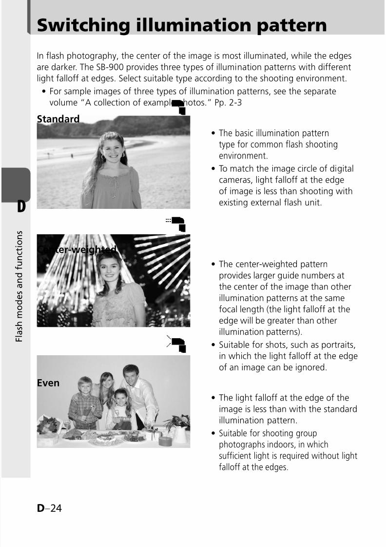
8/8/2019 SB 900 Manual
http://slidepdf.com/reader/full/sb-900-manual 74/142
D–24
D
F l a s h m o d e s a
n d f u n c t i o n s
Switching illumination pattern
EvenThe light falloff at the edge of the
image is less than with the standard
illumination pattern.
Suitable for shooting group
photographs indoors, in which
sufficient light is required without light
falloff at the edges.
•
•
The center-weighted pattern
provides larger guide numbers at
the center of the image than otherillumination patterns at the same
focal length (the light falloff at the
edge will be greater than other
illumination patterns).
Suitable for shots, such as portraits,
in which the light falloff at the edge
of an image can be ignored.
•
•
Center-weighted
Standard
The basic illumination patterntype for common flash shootingenvironment.
To match the image circle of digital
cameras, light falloff at the edge
of image is less than shooting withexisting external flash unit.
•
•
In flash photography, the center of the image is most illuminated, while the edges
are darker. The SB-900 provides three types of illumination patterns with different
light falloff at edges. Select suitable type according to the shooting environment.
For sample images of three types of illumination patterns, see the separatevolume “A collection of example photos.” Pp. 2-3•
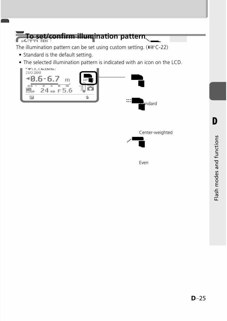
8/8/2019 SB 900 Manual
http://slidepdf.com/reader/full/sb-900-manual 75/142
D–25
D
F l a s h m o d e s a
n d f u n c t i o n s
To set/confirm illumination pattern
The illumination pattern can be set using custom setting. (kC-22)
Standard is the default setting.The selected illumination pattern is indicated with an icon on the LCD.
••
Standard
Center-weighted
Even
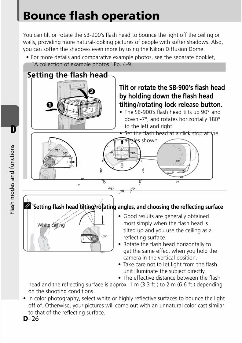
8/8/2019 SB 900 Manual
http://slidepdf.com/reader/full/sb-900-manual 76/142
D–26
D
F l a s h m o d e s a
n d f u n c t i o n s
Bounce flash operation
Setting the flash head
90° 75°
60°
45°
7°
0°
0°
3 0 °
6 0 °
9 0 °
1 2 0
°
1 5 0 °
1 8 0 °
9 0 °
1 2 0
°
1 5 0 °
6 0 °
3 0 °
30
60
90
120
150
You can tilt or rotate the SB-900’s flash head to bounce the light off the ceiling or
walls, providing more natural-looking pictures of people with softer shadows. Also,
you can soften the shadows even more by using the Nikon Diffusion Dome.
For more details and comparative example photos, see the separate booklet,“A collection of example photos” Pp. 4-9.•
Tilt or rotate the SB-900’s flash headby holding down the flash headtilting/rotating lock release button.
The SB-900’s flash head tilts up 90° and
down -7°, and rotates horizontally 180°to the left and right.
Set the flash head at a click stop at the
angles shown.
•
•
t Setting flash head tilting/rotating angles, and choosing the reflecting surface
Good results are generally obtained
most simply when the flash head is
tilted up and you use the ceiling as a
reflecting surface.Rotate the flash head horizontally toget the same effect when you hold thecamera in the vertical position.Take care not to let light from the flashunit illuminate the subject directly.The effective distance between the flash
head and the reflecting surface is approx. 1 m (3.3 ft.) to 2 m (6.6 ft.) dependingon the shooting conditions.
In color photography, select white or highly reflective surfaces to bounce the lightoff of. Otherwise, your pictures will come out with an unnatural color cast similar
to that of the reflecting surface.
•
•
•
•
•
1-2m
90º
White ceiling
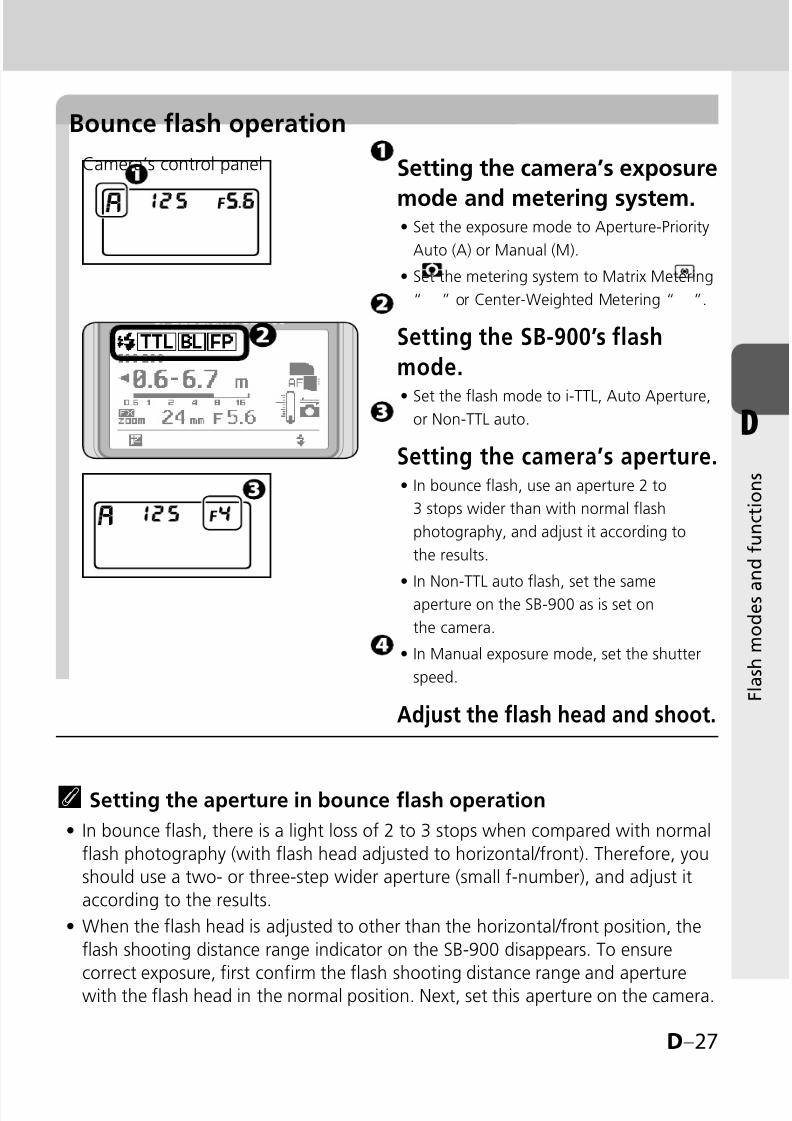
8/8/2019 SB 900 Manual
http://slidepdf.com/reader/full/sb-900-manual 77/142
D–27
D
F l a s h m o d e s a
n d f u n c t i o n s
Bounce flash operation
Setting the camera’s exposure
mode and metering system.Set the exposure mode to Aperture-Priority
Auto (A) or Manual (M).
Set the metering system to Matrix Metering
“ ” or Center-Weighted Metering “ ”.
Setting the SB-900’s flash
mode.
Set the flash mode to i-TTL, Auto Aperture,or Non-TTL auto.
Setting the camera’s aperture.In bounce flash, use an aperture 2 to
3 stops wider than with normal flash
photography, and adjust it according to
the results.
In Non-TTL auto flash, set the sameaperture on the SB-900 as is set on
the camera.
In Manual exposure mode, set the shutter
speed.
Adjust the flash head and shoot.
•
•
•
•
•
•
Camera’s control panel
t Setting the aperture in bounce flash operation
In bounce flash, there is a light loss of 2 to 3 stops when compared with normal
flash photography (with flash head adjusted to horizontal/front). Therefore, you
should use a two- or three-step wider aperture (small f-number), and adjust it
according to the results.
When the flash head is adjusted to other than the horizontal/front position, the
flash shooting distance range indicator on the SB-900 disappears. To ensure
correct exposure, first confirm the flash shooting distance range and aperturewith the flash head in the normal position. Next, set this aperture on the camera.
•
•

8/8/2019 SB 900 Manual
http://slidepdf.com/reader/full/sb-900-manual 78/142
D–28
D
F l a s h m o d e s a
n d f u n c t i o n s
Bounce flash operation
Pull out the bounce card and
the wide-flash adapter and,
while holding the bounce card,
slide the wide-flash adapter
back into place inside theflash head.
To insert the bounce card,
pull out the wide-flash card
again and slide both cards
together back into place.
•
Setting the built-in bounce card
t Using the built-in bounce card
In bounce flash photography, use the SB-900’s built-in bounce card to create a
highlight in the subject’s eyes, making the eyes look more vibrant and avoiding
illuminating the front of the subject.Tilt the flash head up 90° to use this feature most effectively.
•
•

8/8/2019 SB 900 Manual
http://slidepdf.com/reader/full/sb-900-manual 79/142
D–29
D
F l a s h m o d e s a
n d f u n c t i o n s
Attaching the Nikon Diffusion Dome
v Notes when using the Nikon Diffusion Dome
The distance between the camera and subject differs from the centerof the frame to the periphery, so the peripheral area might not be
sufficiently lit in some cases.
•
Attach the Nikon Diffusion Dome as
shown in the illustration with the Nikon
logo facing up.
t Shooting with the Nikon Diffusion Dome
By attaching the provided Nikon Diffusion Dome over the flash head, you can
diffuse the light even more when doing bounce flash, creating extremely soft
light with virtually no shadows.With the camera in either the horizontal or vertical position, you get the same effect.
Good results are generally obtained when the flash head is tilted up 60°.
When the Nikon Diffusion Dome is attached and when the camera's image area
is set to FX format, the zoom position is automatically set at 12 mm, 14 mm or
17 mm, and 8 mm, 10 mm or 11 mm while setting the camera’s image area to
DX format.
•
•
•
•

8/8/2019 SB 900 Manual
http://slidepdf.com/reader/full/sb-900-manual 80/142
D–30
D
F l a s h m o d e s a
n d f u n c t i o n s
Taking close-up photographs with bounce-down flash
7°
0°
When the distance between the camera and subject is less than approx. 2 m (6.6 ft.),
you can take more natural-looking close-up pictures using the wide-flash adapter.
Be careful when using a long lens that the light from the flash is not obstructed
by the lens barrel.Vignetting may occur in close-up flash photography due to the illumination
pattern, lens in use, focal length setting, etc. Therefore, make test shots before
shooting an important assignment.
When the SB-900 is attached to the camera and used as the only flash unit,
tilting down the flash head is recommended to ensure sufficient illumination of
the lower portion of the subject in close-up photography.
A bounce-down icon appears when the flash head is tilted down.
•
•
•
•
Bounce-down icon
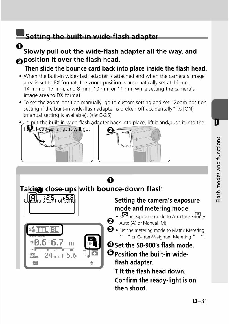
8/8/2019 SB 900 Manual
http://slidepdf.com/reader/full/sb-900-manual 81/142
D–31
D
F l a s h m o d e s a
n d f u n c t i o n s
Taking close-ups with bounce-down flash
Setting the built-in wide-flash adapter
Slowly pull out the wide-flash adapter all the way, andposition it over the flash head.
Then slide the bounce card back into place inside the flash head.When the built-in wide-flash adapter is attached and when the camera's imagearea is set to FX format, the zoom position is automatically set at 12 mm,14 mm or 17 mm, and 8 mm, 10 mm or 11 mm while setting the camera’simage area to DX format.
To set the zoom position manually, go to custom setting and set “Zoom positionsetting if the built-in wide-flash adapter is broken off accidentally” to [ON]
(manual setting is available). (kC-25)
To put the built-in wide-flash adapter back into place, lift it and push it into theflash head as far as it will go.
•
•
•
Setting the camera’s exposuremode and metering mode.
Set the exposure mode to Aperture-Priority
Auto (A) or Manual (M).
Set the metering mode to Matrix Metering
“ ” or Center-Weighted Metering “ ”.
Set the SB-900’s flash mode.
Position the built-in wide-flash adapter.
Tilt the flash head down.
Confirm the ready-light is onthen shoot.
•
•
Camera’s control panel

8/8/2019 SB 900 Manual
http://slidepdf.com/reader/full/sb-900-manual 82/142
D–32
D
F l a s h m o d e s a
n d f u n c t i o n s
Taking close-up photographs with bounce-down flash
A
B
ISO sensitivity 100 200 400 800 1600 3200 6400
Factor (m/ft) 2/6.6 2.8/9.2 4/13 5.6/18 8/26.2 8/26.2 16/52.5
tWhen shooting subjects closer than 0.6 m (2 ft.)
With the SB-900 attached to the camera, sufficient illumination of the subject
cannot be obtained.
In this case, use the SB-900 off-camera by attaching the optional TTL RemoteCord as shown below.
When monitor pre-flashes are fired, distance information from the lens is used
to determine the correct exposure. In this case, position the camera (A) and the
SB-900 (B) at equal distances from the subject.
•
•
•
t Setting the aperture in off-camera close-up flash operation
Calculate the aperture by using this equation and table.To ensure the correct exposure, use an aperture smaller (larger f-number) than
the one obtained from the equation.
f/stop ≥ Factor ÷ Flash-to-subject distance
For example, at an ISO sensitivity of 100 with a subject 0.5 m (1.6 ft.) away andthe wide-flash adapter in place, the suggested aperture is:
f/stop ≥ 2 ÷ 0.5 = 4 (in meters)
f/stop ≥ 6.6 ÷ 1.6 = approx. 4 (in feet)
••
•
v Notes on using a wideangle lens
Generally, when using a wideangle lens, the distance between the
camera and subject differs from the center of the frame to the periphery,
so the peripheral area might not be sufficiently lit in some cases.
•
Use TTL Remote Code SC-29, SC-28 or SC-17.

8/8/2019 SB 900 Manual
http://slidepdf.com/reader/full/sb-900-manual 83/142
D–33
D
F l a s h m o d e s a
n d f u n c t i o n s
Flash photography with color filters
Two types of color filters are supplied with the SB-900 for taking flash pictures
under fluorescent lighting and for use with incandescent/tungsten lighting.
The optional Color Filter Set SJ-3 is available. (kF-11)
Four types of color filters for changing the color of the light from the flash areoptionally available.
For more details on photo examples with color balanced using color filters, see
the separate booklet, “A collection of example photos” P. 10.
•
•
•
Corresponding light source for each type of color compensation filter differs slightly.
FL-G1 provides a greater compensation effect than FL-G2, and TN-A1, greater than
TN-A2. Select the appropriate filter according to the results.
•
Using color filters
v Notes on using color filters
These filters are consumable items. When they fade in color or
deteriorate, replace them with the backup filters provided.Do not use these filters when taking pictures with repeating flash, as
the heat can damage them.The heat generated from the flash head can deform color filters.
However, this will not affect their performance.Scratches on the filters will have no effect on performance unless thefilters fade in color.
To remove dust or dirt, wipe the filter lightly with a soft, clean cloth.
•
•
•
•
•
Filters Purpose
Fluorescent filters (FL-G1, FL-G2)Balance the color of light from the flash to
match that of fluorescent lighting
Incandescent filters (TN-A1, TN-A2)Balance the color of light from the flash to
match that of incandescent or tungsten lighting
Color filters (Optional)Create interesting effects by changing the color
of the light from the filters
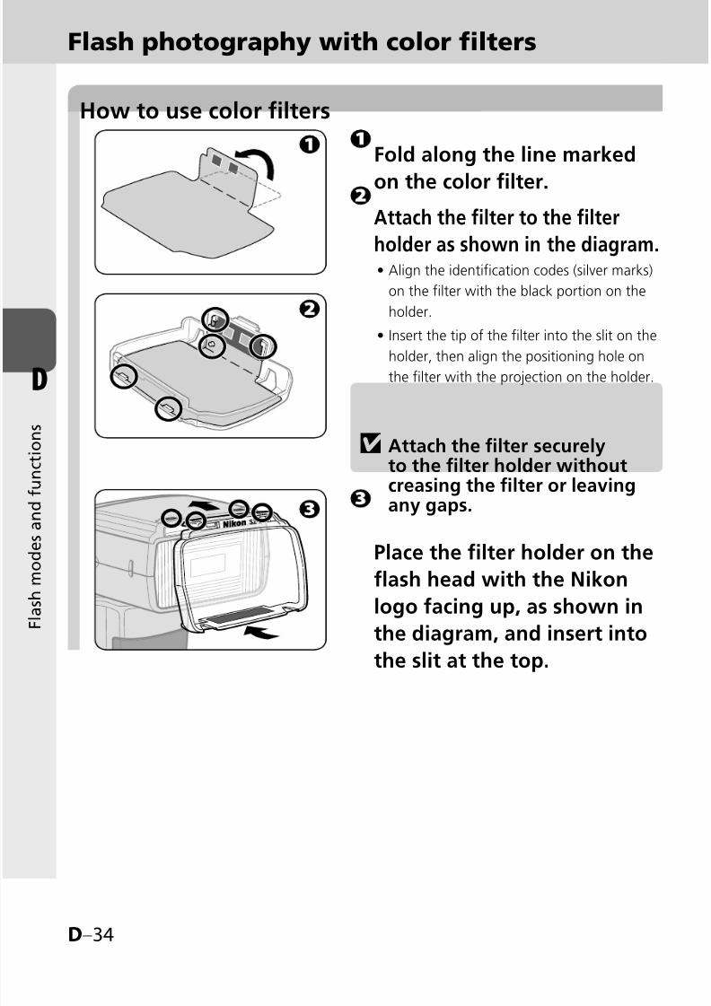
8/8/2019 SB 900 Manual
http://slidepdf.com/reader/full/sb-900-manual 84/142
D–34
D
F l a s h m o d e s a
n d f u n c t i o n s
How to use color filters
Fold along the line marked
on the color filter.
Attach the filter to the filter
holder as shown in the diagram.Align the identification codes (silver marks)
on the filter with the black portion on the
holder.
Insert the tip of the filter into the slit on the
holder, then align the positioning hole on
the filter with the projection on the holder.
•
•
Place the filter holder on the
flash head with the Nikon
logo facing up, as shown in
the diagram, and insert into
the slit at the top.
v Attach the filter securelyto the filter holder withoutcreasing the filter or leavingany gaps.
Flash photography with color filters

8/8/2019 SB 900 Manual
http://slidepdf.com/reader/full/sb-900-manual 85/142
D–35
D
F l a s h m o d e s a
n d f u n c t i o n s
Warning
LCD indication while attachingan FL-G1 filter
Confirm the color filter indicator
is displayed.Filter mounted and filter type indicators will
be displayed.
Do not block the filter detector window.
•
•
If the warning shown in the figure in the
left below appears on the LCD, the filter
is not properly attached. Remove andreattach.
•

8/8/2019 SB 900 Manual
http://slidepdf.com/reader/full/sb-900-manual 86/142
D–36
D
F l a s h m o d e s a
n d f u n c t i o n s
Flash photography with color filters
Balancing light from the flash using color filters
When using SB-900 with a camera equipped with filter detection
(such as D3, D700)When a color filter is attached to the SB-900 while the camera’s white balance
is set to AUTO or FLASH, filter information is automatically transmitted to the
camera, and the camera’s optimum white balance is automatically adjusted to
give the correct color temperature.
When using SB-900 with a camera not equipped with filterdetection (such as D2 series, D300, D200, F6)
Set the camera’s white balance according to the filter in use.
White balance/exposure compensation value depends oncamera in use
■
•
■
•
■
*1 D3 camera with either firmware A or firmware B version 2.00 or later. (kF-10)*2 Set the camera’s white balance and exposure compensation value.
For more details on the white balance, see your camera user’s manual.•
Camera
FilterD3
*1, D700
D2 series, D300, D200,D100, D80, D70 series,D60, D40 series, D1X,D1H
D1, D50
FL-G1 Auto, Flash Not compatible Not compatible
FL-G2 Auto, Flash Not compatible Not compatible
TN-A1 Auto, FlashIncandescent (fine tune +3),+1.0 EV
*2 Not compatible
TN-A2 Auto, FlashDirect sunlight (fine tune+3), +0.3 EV
*2 Not compatible
Color filters(RED, BLUE,YELLOW,AMBER)
Auto, Flash, Directsunlight
Auto, Flash, Direct sunlight(+0.7
*2EV with AMBER)
Auto, Flash, Directsunlight (+0.7
*2EV with
AMBER)

8/8/2019 SB 900 Manual
http://slidepdf.com/reader/full/sb-900-manual 87/142
D–37
D
F l a s h m o d e s a
n d f u n c t i o n s
Making flash output level compensation
Flash output level compensation andexposure compensation
v Canceling flash output level compensation
To cancel, turn the selector dial to return the compensation value to “0”.
The flash output level compensation cannot be canceled by turning theSB-900 off.
•
•
Press the Function button 1
to highlight the Flash output
level compensation value.
Turn the selector dial to set
desired flash output level
compensation value.The compensation value can be set in 1/3
steps from +3.0 to -3.0 EV.
Press the [OK] button.
•
You can make exposure compensation for the flash illuminated subject only
without affecting the background exposure by modifying the SB-900’s flash
output level.
As a basic guide, some plus compensation may be necessary to make the
main subject brighter, and some minus compensation to make it darker.
Flash output level compensation is possible in i-TTL auto flash, Auto Aperture
flash, Non-TTL auto flash and Distance-priority manual flash modes.
•
•
t For cameras with a built-in flash featuring the exposurecompensation function
You can also set the flash output level on the camera. For details, see your
camera user’s manual.
If you compensate the flash output level on both the camera and the SB-900,
the exposure is modified by the sum total of both compensation values.
In this case, the SB-900's LCD panel shows only the compensation value set on the
SB-900.
•
•
•

8/8/2019 SB 900 Manual
http://slidepdf.com/reader/full/sb-900-manual 88/142
D–38
D
F l a s h m o d e s a
n d f u n c t i o n s
Flash output level compensation and exposure compensation
Making exposure compensation
Exposure compensation allows you to make both the subject and background
brighter or darker by intentionally modifying the correct flash exposure. This isuseful when a subject of extremely high or low reflectivity is included in the scene
or when you want to create flash photographs to match your creative preferences.
Some plus compensation may be necessary when the background includes a
highly reflective surface. Likewise, some minus compensation may be required
when the background is dark or includes subjects of low reflectivity.
•
In i-TTL and Auto Aperture flash mode
Make exposure compensation on the camera. For more details, see your camera
user’s manual.
In Non-TTL auto flash and Manual flash mode
In the Non-TTL auto flash mode, the correct exposure can be obtained when
the same aperture is set on the camera as that set on the SB-900. Therefore,
to make exposure compensation, vary the aperture set on the camera while
retaining the aperture set on the SB-900 or vice versa.
In the Manual flash mode, calculate the proper aperture for the correct exposure
from the guide number and the shooting distance (k
D-22). Then, use a largeror smaller aperture on the camera to make exposure compensation.
As a basic guide, set a wider aperture on the camera or lens to make the main
subject brighter or a smaller aperture to make it darker.
■
•
■
•
•
•

8/8/2019 SB 900 Manual
http://slidepdf.com/reader/full/sb-900-manual 89/142
D–39
D
F l a s h m o d e s a
n d f u n c t i o n s
Wireless multiple flash shooting
With the SB-900, the “Advanced” and “SU-4 type” wireless flash operations areavailable.
The Advanced Wireless Lighting mode is automatically set as the default.
Advanced Wireless Lighting is recommended for standard multipleflash photography.
SU-4 type wireless multiple flash, set the wireless flash mode to “SU-4” in the
custom setting. (kC-22)
Flash shooting with Advanced Wireless Lighting
Available when the SB-900 is used with CLS-compatible cameras.
Compatible with i-TTL flash mode.
In this mode, you can divide the remote flash units into three groups and set theflash mode and flash output level compensation values separately for each group.
SU-4 type wireless multiple flash shooting
SU-4 type wireless multiple flash is particularly suitable for shooting fast
moving subjects as both the master flash unit and remote flash units
fire simultaneously.
There are no restrictions as to which cameras can be used.
Speedlight featuring wireless multiple flash capability can be used either as
the master or remote flash unit.Speedlights compatible with TTL auto flash can be used as the master flash
unit. The optional Wireless Slave Flash Controller SU-4 is necessary when you
want to use these Speedlights as remote flash units.
The camera’s built-in flash can also be used as a master flash unit.
•
•
•
•
•
•
•
•
•
•
tMaster flash unit and remote flash unit(s)
In this user’s manual, a flash unit mounted on the camera, the camera’s built-in
flash, or the one directly connected to the camera via a TTL Remote Cord is calledthe master flash unit. All other flash units are called remote flash units.
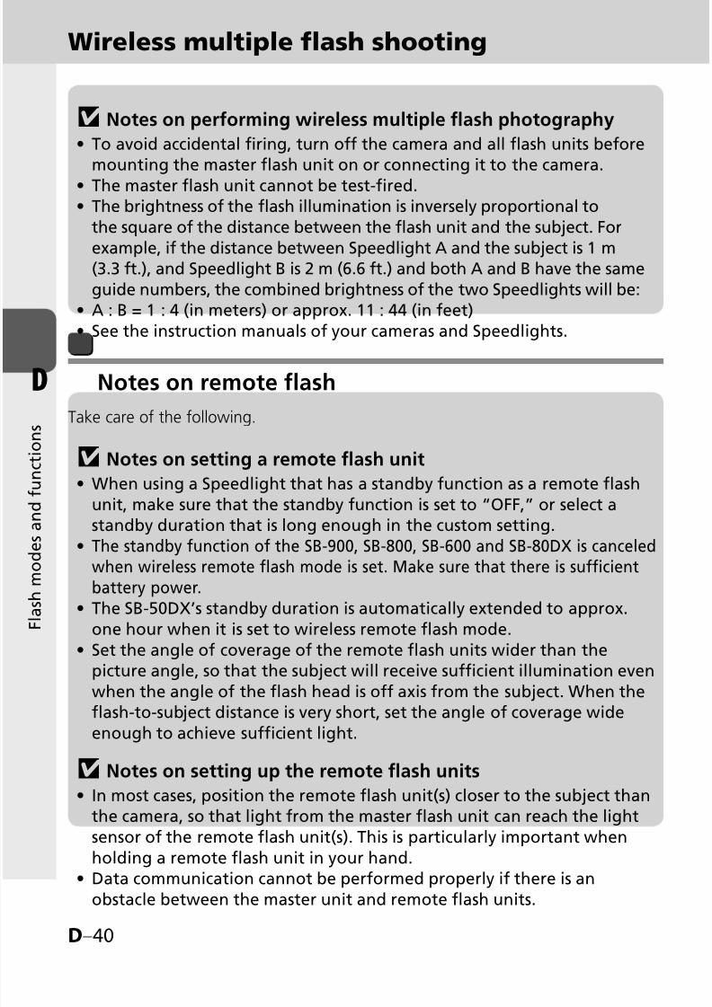
8/8/2019 SB 900 Manual
http://slidepdf.com/reader/full/sb-900-manual 90/142
D–40
D
F l a s h m o d e s a
n d f u n c t i o n s
Wireless multiple flash shooting
v Notes on performing wireless multiple flash photography
To avoid accidental firing, turn off the camera and all flash units beforemounting the master flash unit on or connecting it to the camera.
The master flash unit cannot be test-fired.The brightness of the flash illumination is inversely proportional to
the square of the distance between the flash unit and the subject. For
example, if the distance between Speedlight A and the subject is 1 m(3.3 ft.), and Speedlight B is 2 m (6.6 ft.) and both A and B have the same
guide numbers, the combined brightness of the two Speedlights will be:A : B = 1 : 4 (in meters) or approx. 11 : 44 (in feet)
See the instruction manuals of your cameras and Speedlights.
•
••
•
•
v Notes on setting a remote flash unit
When using a Speedlight that has a standby function as a remote flash
unit, make sure that the standby function is set to “OFF,” or select a
standby duration that is long enough in the custom setting.The standby function of the SB-900, SB-800, SB-600 and SB-80DX is canceledwhen wireless remote flash mode is set. Make sure that there is sufficientbattery power.The SB-50DX’s standby duration is automatically extended to approx.
one hour when it is set to wireless remote flash mode.
Set the angle of coverage of the remote flash units wider than thepicture angle, so that the subject will receive sufficient illumination even
when the angle of the flash head is off axis from the subject. When the
flash-to-subject distance is very short, set the angle of coverage wideenough to achieve sufficient light.
v Notes on setting up the remote flash units
In most cases, position the remote flash unit(s) closer to the subject thanthe camera, so that light from the master flash unit can reach the light
sensor of the remote flash unit(s). This is particularly important when
holding a remote flash unit in your hand.
Data communication cannot be performed properly if there is anobstacle between the master unit and remote flash units.
•
•
•
•
•
•
Notes on remote flash
Take care of the following.

8/8/2019 SB 900 Manual
http://slidepdf.com/reader/full/sb-900-manual 91/142
D–41
D
F l a s h m o d e s a
n d f u n c t i o n s
Take care not to let light from the remote flash unit enter the camera
lens directly or indirectly in i-TTL auto flash mode. Also, prevent lightfrom entering the master flash unit’s light sensor window for Non-TTL
auto flash (in Auto Aperture or Non-TTL auto flash mode). Otherwise,the correct exposure cannot be obtained.
There is no limit to the number of remote flash units that can be used
together. However, when using many remote flash units, light may beunintentionally picked up by the light sensor of the master flash unit
and interfere with correct operation. The practical number of remoteflash units for wireless multiple flash shooting are three. In Advanced
Wireless Lighting, for practical purposes, the number of remote flashunits should be limited to three for one group.
Use the provided Speedlight Stand AS-21 for stable placement of the
remote flash units.Be sure to perform test firing after setting up all flash units.
•
•
•
•
Using the Speedlight Stand
Use the provided Speedlight Stand AS-21 for stable placement of the remote flash units.
■
Attach the SB-900 to the Speedlight Stand in the same way that you attach
it to the camera’s accessory shoe. The same is true when detaching it from
the camera.
Speedlights SB-15 and SB-27 cannot be used with the AS-21.
•
•

8/8/2019 SB 900 Manual
http://slidepdf.com/reader/full/sb-900-manual 92/142
D–42
D
F l a s h m o d e s a
n d f u n c t i o n s
Wireless multiple flash shooting
Confirming flash operation using the ready-light or sound monitor
Confirming shooting situations in wireless multipleflash operation
You can confirm wireless multiple flash operation by checking the ready-light onthe SB-900 or the sound monitor during and after shooting.
When the SB-900 is used as a wireless remote flash unit, you can monitor its operationby listening to the sound monitor. This function can be activated or canceled usingcustom setting (kC-24). This function is set to activate as the default.To save battery power, the ready-lights on the remote flash units can be turned
off in the custom setting. The rear ready-light is set to light up and the front
ready-light is set to blink as the default. (kC-24)
•
•
Ready-light of
master flash unit
Ready-light of
remote flash unitSound monitor Speedlight condition
Lights up
The rear ready-light lights up andthe front ready-light blinks.
One beep Ready to fire
Lights up or doesnot come on (notblinking)
The rear ready-light lights up,and the frontready-light blinksor goes out.
Two short beeps Fired properly
Blinks for approx.3 sec.
Quickly blinks forapprox. 3 sec.
Three long beepsfor approx. 3 sec.
Both the master and remote flash units havefired at full output but light may have beeninsufficient for correct exposure. Use a wideraperture and reshoot.
Lights up or does
not come on (notblinking)
Quickly blinks forapprox. 3 sec.
Three long beepsfor approx. 3 sec.
The light sensor of remote flash could notreceive correctly the command light frommaster flash. The light sensor could not detectwhen to stop firing in sync with the master
flash unit, because a strong reflection from theremote flash unit itself or light from anotherremote flash unit may have entered the lightsensor window. Change the direction orposition of the remote flash unit and reshoot.
Normal operation Normal operation
Warning chime ringstwice (when theSB-900 detects hightemperature), or once(for each flash firing)
The SB-900’s temperature has risen asa result of the flash being fired multipletimes in quick succession. Wait until theSB-900 cools down.
Goes out Goes out Warning chimerings twice.
The SB-900’s temperature has risen to a certainlevel and the SB-900 enters protective shutdownmode. Wait until the SB-900 cools down.
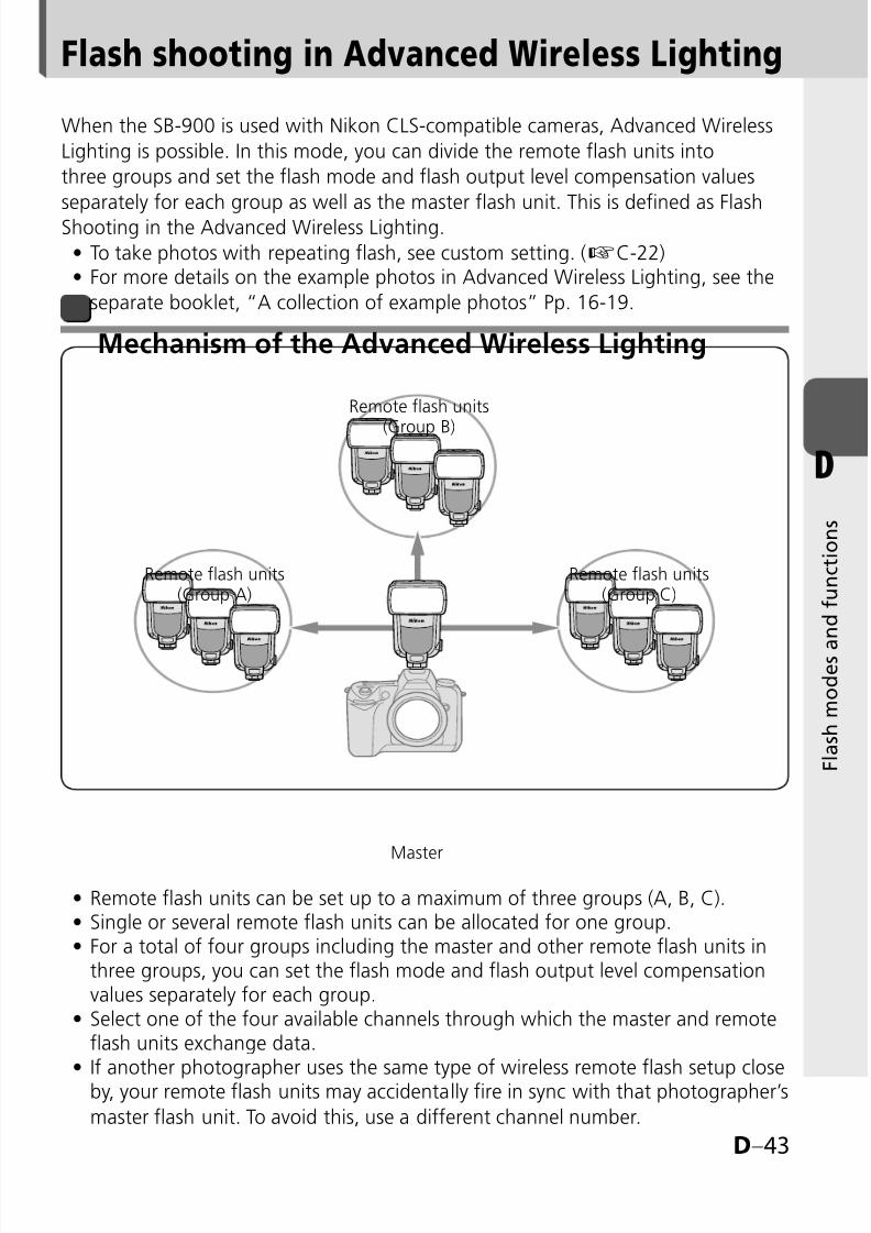
8/8/2019 SB 900 Manual
http://slidepdf.com/reader/full/sb-900-manual 93/142
D–43
D
F l a s h m o d e s a
n d f u n c t i o n s
Flash shooting in Advanced Wireless Lighting
Mechanism of the Advanced Wireless Lighting
When the SB-900 is used with Nikon CLS-compatible cameras, Advanced Wireless
Lighting is possible. In this mode, you can divide the remote flash units into
three groups and set the flash mode and flash output level compensation values
separately for each group as well as the master flash unit. This is defined as Flash
Shooting in the Advanced Wireless Lighting.
To take photos with repeating flash, see custom setting. (kC-22)For more details on the example photos in Advanced Wireless Lighting, see the
separate booklet, “A collection of example photos” Pp. 16-19.
••
Remote flash units can be set up to a maximum of three groups (A, B, C).Single or several remote flash units can be allocated for one group.For a total of four groups including the master and other remote flash units inthree groups, you can set the flash mode and flash output level compensationvalues separately for each group.Select one of the four available channels through which the master and remoteflash units exchange data.If another photographer uses the same type of wireless remote flash setup closeby, your remote flash units may accidentally fire in sync with that photographer’s
master flash unit. To avoid this, use a different channel number.
•••
•
•
Master
Remote flash units
(Group B)
Remote flash units(Group A)
Remote flash units(Group C)

8/8/2019 SB 900 Manual
http://slidepdf.com/reader/full/sb-900-manual 94/142

8/8/2019 SB 900 Manual
http://slidepdf.com/reader/full/sb-900-manual 95/142
D–45
D
F l a s h m o d e s a
n d f u n c t i o n s
You can set the SB-900 to Advanced Wireless Lighting using the Power ON-OFF
switch/wireless setting switch.Turn the switch while holding down the button on the center.•
Align the index on the Power
ON-OFF switch/wireless setting
switch to MASTER.
• Align the index on the Power
ON-OFF switch/wireless setting
switch to REMOTE.
•
Setting the SB-900 asthe master flash unit
Setting the SB-900 asthe remote flash unit
Setting the SB-900 to Advanced Wireless Lighting

8/8/2019 SB 900 Manual
http://slidepdf.com/reader/full/sb-900-manual 96/142
D–46
D
F l a s h m o d e s a
n d f u n c t i o n s
*1 Auto Aperture flash is automatically set. When the SB-900 cannot receive lens
information such as focal length and aperture, the flash mode automatically switchesto Non-TTL auto flash.
*2 If another photographer uses the same type of wireless remote flash setup close by,
your remote flash units may accidentally fire in sync with that photographer’s master
flash unit. To avoid this, use a different channel number.
In this mode, set the following items on either the master flash unit or the remote
flash units.
Item
Speedlight
to be set Remarks
Flash modeMaster flash
unit
The following five flash modes are available:
i-TTL mode
Auto Aperture flash*1
Non-TTL auto flash*1
Manual flash
Flash canceled
Set the flash mode of the remote flash units on the
master flash unit.
The flash mode can be set independently on the
master flash unit and for each group of remote
flash units.
•
·
·
·
·
·
•
•
Flash
output level
compensation
Master flash
unit
Flash output level compensation values of the
remote flash units can also be set on the master
flash unit.
The flash output level compensation values can be
set independently on the master flash unit and foreach group of remote flash units.
•
•
Channel*2
Master and
remote flash
units
Select one of the four available channels.
Be sure to set the same channel number for both
the master flash unit and remote flash units.
•
•
GroupRemote flash
unitA maximum of 3 groups (A, B, C)•
Flash shooting in Advanced Wireless Lighting
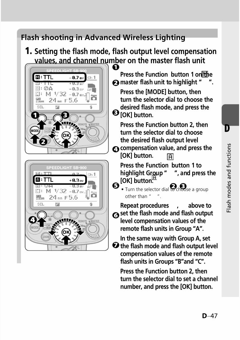
8/8/2019 SB 900 Manual
http://slidepdf.com/reader/full/sb-900-manual 97/142
D–47
D
F l a s h m o d e s a
n d f u n c t i o n s
Flash shooting in Advanced Wireless Lighting
1. Setting the flash mode, flash output level compensation
values, and channel number on the master flash unit
Press the Function button 1 on themaster flash unit to highlight “ ”.
Press the [MODE] button, thenturn the selector dial to choose thedesired flash mode, and press the[OK] button.
Press the Function button 2, thenturn the selector dial to choosethe desired flash output levelcompensation value, and press the[OK] button.
Press the Function button 1 tohighlight Group “ ”, and press the
[OK] button.Turn the selector dial to choose a group
other than “ ”.
Repeat procedures , above toset the flash mode and flash outputlevel compensation values of theremote flash units in Group “A”.
In the same way with Group A, setthe flash mode and flash output levelcompensation values of the remoteflash units in Groups “B”and “C”.
Press the Function button 2, thenturn the selector dial to set a channelnumber, and press the [OK] button.
•
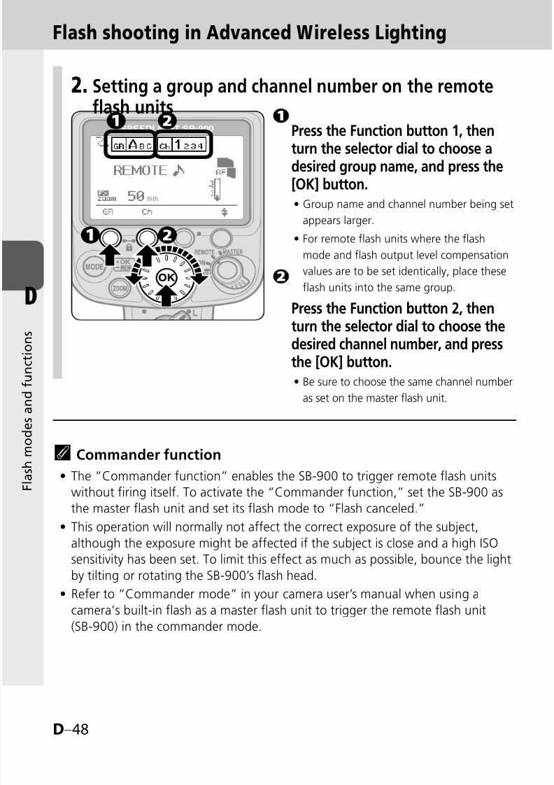
8/8/2019 SB 900 Manual
http://slidepdf.com/reader/full/sb-900-manual 98/142
D–48
D
F l a s h m o d e s a
n d f u n c t i o n s
2. Setting a group and channel number on the remoteflash units
Press the Function button 1, thenturn the selector dial to choose adesired group name, and press the[OK] button.
Group name and channel number being set
appears larger.
For remote flash units where the flash
mode and flash output level compensation
values are to be set identically, place theseflash units into the same group.
Press the Function button 2, thenturn the selector dial to choose thedesired channel number, and pressthe [OK] button.
Be sure to choose the same channel number
as set on the master flash unit.
•
•
•
t Commander function
The “Commander function” enables the SB-900 to trigger remote flash units
without firing itself. To activate the “Commander function,” set the SB-900 as
the master flash unit and set its flash mode to “Flash canceled.”
This operation will normally not affect the correct exposure of the subject,
although the exposure might be affected if the subject is close and a high ISO
sensitivity has been set. To limit this effect as much as possible, bounce the light
by tilting or rotating the SB-900’s flash head.
Refer to “Commander mode” in your camera user’s manual when using a
camera’s built-in flash as a master flash unit to trigger the remote flash unit
(SB-900) in the commander mode.
•
•
•
Flash shooting in Advanced Wireless Lighting

8/8/2019 SB 900 Manual
http://slidepdf.com/reader/full/sb-900-manual 99/142
D–49
D
F l a s h m o d e s a
n d f u n c t i o n s
Repeating flash shooting
In the Advanced Wireless Lighting, the repeating flash operation is possible.
The Repeating flash mode can be activated or canceled using the customsetting. (kC-22)
•
In the repeating flash mode, the flash mode can be set to either the Repeatingflash activated or Repeating flash canceled only.
In the repeating flash mode, all settings of flash output level, frequency and the
number of repeating flashes per frame are common to both the master flash
unit and remote flash units.
Referring to “Repeating flash shooting”, set the flash output level, frequency,
and the number of repeating flashes per frame. (kD-17)
•
•
•
LCD display in the repeating flash mode
Number ofrepeatingflashes perframe
Frequency (Hz)
Flash output level
Channel number
Flash firing of master flash unit and remote flash units(ON/OFF) in Group A (B, C) activated/canceled
Repeating flash mode
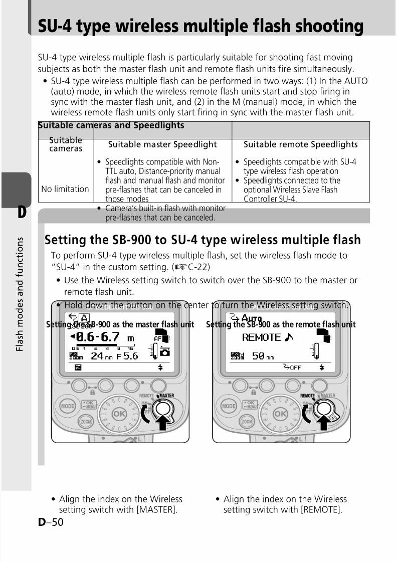
8/8/2019 SB 900 Manual
http://slidepdf.com/reader/full/sb-900-manual 100/142
D–50
D
F l a s h m o d e s a
n d f u n c t i o n s
SU-4 type wireless multiple flash shooting
Setting the SB-900 to SU-4 type wireless multiple flash
SU-4 type wireless multiple flash is particularly suitable for shooting fast moving
subjects as both the master flash unit and remote flash units fire simultaneously.
SU-4 type wireless multiple flash can be performed in two ways: (1) In the AUTO(auto) mode, in which the wireless remote flash units start and stop firing insync with the master flash unit, and (2) in the M (manual) mode, in which thewireless remote flash units only start firing in sync with the master flash unit.
•
Suitable cameras and Speedlights
To perform SU-4 type wireless multiple flash, set the wireless flash mode to
“SU-4” in the custom setting. (kC-22)
Use the Wireless setting switch to switch over the SB-900 to the master or
remote flash unit.Hold down the button on the center to turn the Wireless setting switch.
•
•
Align the index on the Wirelesssetting switch with [MASTER].
• Align the index on the Wirelesssetting switch with [REMOTE].
•
Setting the SB-900 as the master flash unit Setting the SB-900 as the remote flash unit
Suitablecameras Suitable master Speedlight Suitable remote Speedlights
No limitation
Speedlights compatible with Non-TTL auto, Distance-priority manualflash and manual flash and monitorpre-flashes that can be canceled in
those modesCamera’s built-in flash with monitorpre-flashes that can be canceled.
•
•
Speedlights compatible with SU-4type wireless flash operationSpeedlights connected to theoptional Wireless Slave Flash
Controller SU-4.
•
•
8/8/2019 SB 900 Manual
http://slidepdf.com/reader/full/sb-900-manual 101/142
D–51
D
F l a s h m o d e s a
n d f u n c t i o n s
Master and remote flash units’ available flash modesin the SU-4 type wireless multiple flash operation
Master flash unit
Non-TTL auto, Distance-priority manual flash and manual flash modes can
be set.
Press the [MODE] button, then turn the selector dial to choose the desired
flash mode.
When the SB-900 is set as the master flash unit, monitor pre-flashes will not fire.
Remote flash unitAUTO (auto) and M (manual) modes are available.
Press the [MODE] button, then turn the selector dial to choose AUTO or M mode.
(auto) mode:
In the A mode, the remote flash units start and stop firing in sync with the
master flash unit.
The maximum distance the SB-900’s light sensor can detect is approximately
7 m (23 ft.) or less in the front position of the master unit.
(manual) mode:
In the M mode, the remote flash units only start firing in sync with the
master flash unit.
The maximum detectable distance of the SB-900’s light sensor can detect is
approx. 40 m (131 ft.) in the front position of the master unit.
The flash output level can be set from M1/1 to M1/128.
•
•
•
•
•
•
•
•
•
•

8/8/2019 SB 900 Manual
http://slidepdf.com/reader/full/sb-900-manual 102/142
D–52
D
F l a s h m o d e s a
n d f u n c t i o n s
SU-4 type wireless multiple flash shooting
v Canceling monitor pre-flashes
In SU-4 type wireless multiple flash, cancel the monitor pre-flashes of themaster flash unit, since monitor pre-flashes cause incorrect exposure.
When the SB-900 is set as the master flash unit, monitor pre-flashes willnot fire.
For other Speedlights, be sure to cancel the master flash unit’s monitor
pre-flashes. For how to cancel the master flash unit’s monitor pre-flashes, refer to the user's manual of each Nikon Speedlight.
•
•

8/8/2019 SB 900 Manual
http://slidepdf.com/reader/full/sb-900-manual 103/142
D–53
D
F l a s h m o d e s a
n d f u n c t i o n s
Procedures for SU-4 type wireless multiple flash shooting
Camera’s control panel
Master flash unit’s LCD panel
v To prevent the remote flash units from firing accidentallyWith the SU-4 type wireless multiple flash, note the following:
Do not leave the power of the remote flash units on. Otherwise,ambient electric noise due to a discharge of static electricity, or other
electromagnetic wave, etc. may trigger them accidentally. Be sure to
turn the power off.
•
Remote flash unit’s LCD panel
Set the camera’s exposure mode
to A (Aperture-Priority Auto) orM (Manual).
Set up all Speedlights (both
master and remote flash units) as
the SU-4 type wireless multiple
flash mode.
Set the flash mode of the remote
flash units to AUTO (auto) or
M (manual).
Set the flash mode of the master
flash unit.Set it to Non-TTL auto, Distance-priority manual or
Manual flash mode, when the remote flash unitsare set to AUTO (auto).
Set it to Manual flash mode, when the remote
flash units are set to M (manual).
Confirm the aperture, flash
output level and flash shooting
distance, then shoot.
•
•
8/8/2019 SB 900 Manual
http://slidepdf.com/reader/full/sb-900-manual 104/142
D–54
D
F l a s h m o d e s a
n d f u n c t i o n s
SU-4 type wireless multiple flash shooting
t Adjusting the flash output level of the remote flash units in theM (manual) mode
Adjusting the flash output level manually
Use the following equation to determine the proper manual flash output level of
the remote flash unit, depending on your creative preferences.
GN = F × D, where GN is the guide number of the remote flash unit (inmeters/feet), F is the lens aperture in use, and D is the distance betweenthe remote flash unit and the subject (in meters/feet).
For example, with the SB-900’s zoom position adjusted to 18 mm, using an
ISO sensitivity of 100, standard illumination pattern, in FX-format, shooting a
subject at a distance of 2 m (6.6 ft.) with a lens aperture of f/5.6, thenGN (in meters)= 5.6 x 2 = 11.2, or GN (in feet)= 5.6 x 6.6 = approx. 37.
Therefore, to get the correct exposure, refer to the Guide Number table
(kF-19) and adjust the flash output level to M1/4.
Refer to “Determining the aperture, flash output level and flash shooting
distance in the Distance-priority manual and Manual flash mode” (kD-22).
Adjusting the flash output level in Non-TTL auto flash (A);
applicable when using a Speedlight compatible with Non-TTLauto flash mounted on the SU-4 (optional)
Non-TTL auto flash (A) can also be selected on the remote flash unit. In this
case, the remote flash unit controls the flash output based on the aperture and
ISO sensitivity set on the remote flash unit, and automatically stops firing in sync
with the master flash unit (kD-8).
Set the same ISO sensitivity on the remote flash unit as set on your camera.
Set the same aperture on both the lens and the remote flash unit to obtain the
correct exposure.Depending on your creative preferences, you can intentionally overexpose or
underexpose the picture by modifying the aperture.
The above setting is applicable only when both the master and remote flash
units face the same direction.
Refer to “Flash shooting distance range” (kF-16) for more details.
■
•
•
■
•
•
•
•

8/8/2019 SB 900 Manual
http://slidepdf.com/reader/full/sb-900-manual 105/142
D–55
D
F l a s h m o d e s a
n d f u n c t i o n s
Available functions to be set on the camera
The following functions are available when used with cameras so equipped. Set
these functions on the camera. They cannot be set on the SB-900 directly.
For detailed information regarding camera functions and settings, refer to your
camera user’s manual.Auto FP High-Speed Sync mode
High-Speed flash synchronization at a compatible camera’s highest shutter speed is possible.
The Auto FP High-Speed Sync mode is automatically set when the shutter speed
exceeds the camera’s sync shutter speed.
This is useful when you want to use a wider aperture to achieve shallow depth
of field to blur the background without worrying about sync shutter speed.
Auto FP High-Speed sync also operates in the Advanced Wireless Lighting mode.
Available flash modes are i-TTL, Auto Aperture flash with monitor pre-flashes,
Non-TTL auto flash with monitor pre-flashes, Distance-priority manual flash, and
Manual flash when using a single flash unit.
For flash shooting distance range in the TTL auto flash mode and the guide
numbers in the Auto FP High-Speed Sync mode, refer to “Specifications.”
Flash Value Lock (FV Lock)
Using FV Lock, you can lock in the appropriate flash exposure, while keeping the
subject illumination constant even if you change the composition.The flash exposure (brightness) remains the same even when you change
the aperture or zoom the lens in and out, because the flash output level
automatically follows.
It is possible to take up to a several number of frames during FV Lock operation.
Available flash modes are i-TTL, Auto Aperture flash with monitor pre-flashes
and Non-TTL auto flash with monitor pre-flashes.
FV stands for Flash Value, meaning flash illuminated subject exposure.
Slow-sync flashThe flash is controlled at a slow shutter speed to obtain the correct exposure for
both the main subject and background in low-light situations.
Since slow shutter speeds are normally used, use of a tripod is recommended to
prevent camera shake.
For more details on the example photos, see the separate booklet, “A collection
of example photos” Pp. 12-15.
•
■
•
•
•
•
•
■
•
•
•
•
■
•
•

8/8/2019 SB 900 Manual
http://slidepdf.com/reader/full/sb-900-manual 106/142
D–56
D
F l a s h m o d e s a
n d f u n c t i o n s
Available functions to be set on the camera
Red-eye reduction/Red-eye reduction with slow-sync flash
To prevent your subject’s eyes from appearing red in color pictures shot in dim light,
the SB-900 fires three flashes at reduced output just before the picture is taken.
In the Red-eye reduction with slow sync flash, red-eye reduction is combinedwith slow-sync flash.
Since slow shutter speeds are normally used in red-eye reduction with slow-sync
flash, use of a tripod is recommended to prevent camera shake.
Rear-curtain sync
In normal flash photography, when shooting fast-moving subjects at slow shutter
speeds, unnatural-looking pictures can occur, because the subject frozen by the
flash appears behind or within the blurred movement (see photo below right).
Rear-curtain flash sync creates a picture in which the blur of a moving subject (forexample, the taillights of a car) appears behind the subject and not in front.
In front-curtain sync, the flash fires immediately after the front curtain opens
completely; in rear-curtain sync, the flash fires just before the rear curtain starts
to close.
Since slow shutter speeds are usually used, use a tripod to prevent camera shake.
This function does not operate in Repeating flash operation.
In multiple flash, the master flash unit can be set to either front-curtain or rear-
curtain sync flash. However, the remote units cannot be set to rear-curtain sync
flash. (kD-39)
■
•
•
■
•
•
•
•
Front-curtain sync Rear-curtain sync
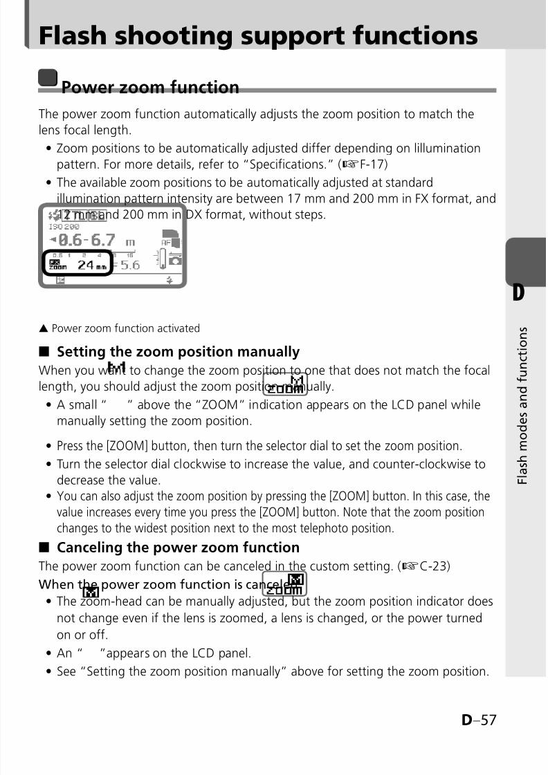
8/8/2019 SB 900 Manual
http://slidepdf.com/reader/full/sb-900-manual 107/142
D–57
D
F l a s h m o d e s a
n d f u n c t i o n s
Flash shooting support functions
Power zoom function
The power zoom function automatically adjusts the zoom position to match the
lens focal length.Zoom positions to be automatically adjusted differ depending on lillumination
pattern. For more details, refer to “Specifications.” (kF-17)
The available zoom positions to be automatically adjusted at standard
illumination pattern intensity are between 17 mm and 200 mm in FX format, and
12 mm and 200 mm in DX format, without steps.
▲ Power zoom function activated
Setting the zoom position manually
When you want to change the zoom position to one that does not match the focal
length, you should adjust the zoom position manually.
A small “ ” above the “ZOOM” indication appears on the LCD panel whilemanually setting the zoom position.
Press the [ZOOM] button, then turn the selector dial to set the zoom position.
Turn the selector dial clockwise to increase the value, and counter-clockwise to
decrease the value.
You can also adjust the zoom position by pressing the [ZOOM] button. In this case, the
value increases every time you press the [ZOOM] button. Note that the zoom position
changes to the widest position next to the most telephoto position.
Canceling the power zoom functionThe power zoom function can be canceled in the custom setting. (kC-23)
When the power zoom function is canceled
The zoom-head can be manually adjusted, but the zoom position indicator does
not change even if the lens is zoomed, a lens is changed, or the power turned
on or off.
An “ ”appears on the LCD panel.
See “Setting the zoom position manually” above for setting the zoom position.
•
•
■
•
•
•
•
■
•
•
•
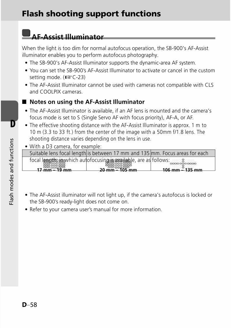
8/8/2019 SB 900 Manual
http://slidepdf.com/reader/full/sb-900-manual 108/142
D–58
D
F l a s h m o d e s a
n d f u n c t i o n s
Flash shooting support functions
AF-Assist Illuminator
When the light is too dim for normal autofocus operation, the SB-900’s AF-Assist
illuminator enables you to perform autofocus photography.The SB-900’s AF-Assist Illuminator supports the dynamic-area AF system.
You can set the SB-900’s AF-Assist Illuminator to activate or cancel in the custom
setting mode. (kC-23)
The AF-Assist Illuminator cannot be used with cameras not compatible with CLS
and COOLPIX cameras.
Notes on using the AF-Assist Illuminator
The AF-Assist Illuminator is available, if an AF lens is mounted and the camera’s
focus mode is set to S (Single Servo AF with focus priority), AF-A, or AF.
The effective shooting distance with the AF-Assist Illuminator is approx. 1 m to10 m (3.3 to 33 ft.) from the center of the image with a 50mm f/1.8 lens. Theshooting distance varies depending on the lens in use.
With a D3 camera, for example:Suitable lens focal length is between 17 mm and 135 mm. Focus areas for eachfocal length, in which autofocusing is available, are as follows:
The AF-Assist illuminator will not light up, if the camera’s autofocus is locked or
the SB-900’s ready-light does not come on.
Refer to your camera user’s manual for more information.
•
•
•
■
•
•
•
•
•
17 mm – 19 mm 20 mm – 105 mm 106 mm – 135 mm

8/8/2019 SB 900 Manual
http://slidepdf.com/reader/full/sb-900-manual 109/142
D–59
D
F l a s h m o d e s a
n d f u n c t i o n s
tUsing the SB-900 off-cameraWhen using the SB-900 off-camera with the TTL Remote Cord SC-29, autofocus
flash photography in dim light is possible, because the SC-29 features an AF-Assist
illuminator function. (kF-11)
t For cameras having a built-in Speedlight
Even when the camera’s AF-assist illuminator is set to activate, the SB-900’s
AF-Assist illuminator is given priority and the camera’s AF-Assist illuminator does
not light up.
The camera’s AF-assist illuminator lights up only when the SB-900’s AF-Assistilluminator is canceled.
•
•
v If autofocus is impossible while using the AF-Assistilluminator, focus manually.
If the focus indicator does not appear in the camera’s viewfinder even though
the AF-Assist illuminator turns on, focus manually.
AF-assist illuminator/flash firing off
You can set the SB-900’s AF-Assist Illuminator and flash firing to activate or cancelin the custom setting. (kC-23)
: AF-Assist Illuminator is activated. (Default)
: AF-Assist Illuminator is canceled. No “AF” appears.
: The SB-900’s actual flash firing is canceled.
The AF-Assist Illuminator only comes on
■

8/8/2019 SB 900 Manual
http://slidepdf.com/reader/full/sb-900-manual 110/142
D–60
D
F l a s h m o d e s a
n d f u n c t i o n s
Flash shooting support functions
Setting the ISO sensitivity
The ISO sensitivity is automatically set based on the information transmitted from
the camera to the Speedlight.Setting the ISO sensitivity manually
You can set the ISO sensitivity manually using the custom setting. (kC-24)
The available ISO sensitivity range is ISO 3 to 8000. Note that the ISO sensitivity
set on the camera is given priority.
Test firing function
You can determine whether the subject will receive the correct exposure by test
firing the SB-900 before actually taking the picture by pressing the [Test firing]
button.
The SB-900 fires at M1/128 flash output in the i-TTL flash mode. The amount of
flash output can be modified in the custom setting. (kC-23)
In Auto Aperture/Non-TTL auto flash operations, the SB-900 fires at a flash
output controlled by the aperture set.
In the Manual mode, the SB-900 fires at the flash output value set.
In wireless multiple flash photography, the SB-900 does not perform test firing if
it is set as a master flash unit.
Setting the test firingSet to activate the test firing in the custom setting. (kC-22)
When the test firing is activated, the test firing icon appears on the LCD panel.
■
•
•
•
•
•
■
•
8/8/2019 SB 900 Manual
http://slidepdf.com/reader/full/sb-900-manual 111/142
D–61
D
F l a s h m o d e s a
n d f u n c t i o n s
Modeling illuminator function
Press the [Test firing] button and the flash fires repeatedly at a reduced flash outputlevel. This is useful for checking the illumination and the shadows cast on thesubject before actually taking the picture.
The flash fires as a Modeling illuminator for a maximum of approx. 1.5 seconds.
This function operates only after the ready-light comes on.
Setting the modeling illuminator using the [Test firing] buttonSet to activate the Modeling illuminator in the custom setting. (kC-22)
When the Modeling illuminator is activated, the modeling illuminator iconappears on the LCD panel.
Modeling illumination using camera’s depth-of-preview buttonWhen the depth-of-preview button on a camera compatible with the modelingillumination is pressed, the Modeling illuminator fires. For details, see your camerauser’s manual.
This function can be performed without activating the SB-900’s Modelingilluminator in the custom setting.
Modeling illuminator in the Advanced Wireless Lighting (kD-43)
When the [Test firing] button on the master flash unit is pressed, the Modelingilluminator of the highlighted master unit or the remote flash unit group fires at theset flash output value.
If the master flash unit and grouped remote flash units are not highlighted, theModeling illuminator on the master flash unit only fires (except when the masterflash unit’s flash firing is set to cancel.)
When the camera’s depth-of-preview button is pressed, the Modelingilluminators of the master and all other remote flash units fire at the set flashoutput value at the selected mode.
Modeling illuminator in SU-4 type wireless multiple flashoperation (kD-50)
Only the Modeling illuminator on the master flash unit fires.
SU-4 remote flash units also fire according to the modeling illumination of the
master flash unit, but these are not Modeling illuminators.
v Do not release the shutter while the Modeling illuminator is firingIf you release the shutter while the master flash unit’s Modeling illuminator is
firing, correct exposure cannot be obtained.
•
•
■
•
■
•
■
•
•
■
•

8/8/2019 SB 900 Manual
http://slidepdf.com/reader/full/sb-900-manual 112/142
D–62
D
F l a s h m o d e s a
n d f u n c t i o n s
FX/DX selection
When mounted on a camera that can select an image area between FX-format (36
× 24) and DX-format (24 × 16), the SB-900 automatically selects the suitable lightdistribution angle, in accordance with the camera’s image area setting. For details,
see your camera user’s manual.
Automatic switching between FX-/DX-format
Based on information from the camera, the light distribution angle is automatically
switched according to the FX-format (36 × 24) and DX-format (24 × 16).
Icon on the LCD panel shows the status of the format set.
: DX-format
: FX-format
t / indication with power zoom on
LCD icon varies according to the camera in use.
/ icon appears: D3, D700
icon appears: D300, D60, D40 series
Neither nor icons appear: Cameras not equipped with / image
area selection
Manual switching of light distribution angle
When manual zoom position setting is activated, the light distribution angle can be
switched manually in the custom setting. (kC-23)
Icon on the LCD panel shows the format set.
: DX-format
: Power zoom function is canceled in the custom setting
: FX-format
: Power zoom function is canceled in the custom setting
■
•
•
•
•
■
•
Flash shooting support functions

8/8/2019 SB 900 Manual
http://slidepdf.com/reader/full/sb-900-manual 113/142
E–1
E
F o r u
s e w i t h c a m e r a s o t h e r t h a n C L S
- c o m p a t i b l e S L R c a m e
r a s
E–1
E For use with cameras other thanCLS compatible SLR cameras
Refer to this chapter when using the SB-900 withcameras other than CLS-compatible SLR cameras.
Using the SB-900 with non-CLS-compatible
SLR cameras .........................................................................E-2
For use with i-TTL-compatible
COOLPIX cameras ................................................................E-3
•
•

8/8/2019 SB 900 Manual
http://slidepdf.com/reader/full/sb-900-manual 114/142
E–2
E
F o r u
s e w i t h c a m e r a s o t h e r t h a n C L S
- c o m p a t i b l e S L R c a m e
r a s
Using the SB-900 with non-CLS-compatibleSLR cameras
Differences between CLS-compatible cameras andthose not compatible with CLS
Using the SB-900 with non-CLS-compatible SLR cameras is possible with the
exception of some functions.
The SB-900’s available functions vary depending on cameras in use.
See your camera user’s manual as well.
•
•
CLS-compatible cameras Non-CLS-compatible cameras
Camera
communication
icon
Displayed Not displayed
Available flash mode
i-TTL mode
Auto Aperture flash
Non-TTL auto flash
Distance-priority manual flash
Manual flash
Repeating flash
•
•
•
•
•
•
Non-TTL auto flash
Distance-priority manual flash
Manual flash
Repeating flash
•
•
•
•
ISO sensitivity setting Auto Custom set
Available wireless
multiple flashshooting
Advanced Wireless Lighting
SU-4 type
•
• SU-4 type•
Flash shooting using
color filtersPossible
Possible
(Filter information not
transferred)
FV Lock flash Possible Not possible
Auto FP High-Speed
sync.Possible Not possible
Rear-curtain syncflash Possible Depends on the camera in use
AF-Assist illuminatorPossible (supporting dynamic-area
AF system)Not possible
Firmware updatePossible
(with compatible cameras only)Not possible
8/8/2019 SB 900 Manual
http://slidepdf.com/reader/full/sb-900-manual 115/142
E–3
E
F o r u
s e w i t h c a m e r a s o t h e r t h a n C L S
- c o m p a t i b l e S L R c a m e
r a s
For usage with i-TTL-compatibleCOOLPIX cameras
Using the SB-900 with i-TTL compatible COOLPIX cameras is possible, with the
exception of some functions.
The SB-900’s available functions vary depending on cameras in use.
See your camera user’s manual together.
•
•
i-TTL compatible COOLPIX cameras
Available flash mode
i-TTL mode
Non-TTL auto flash
Distance-priority manual flash
Manual flash
•
•
•
•
Available wireless multiple flash
shooting*1 SU-4 type
FV Lock flash Not possible
Auto FP High-Speed sync. Not possible
AF-Assist illuminator Not possible
Firmware update Not possible
For use with i-TTL compatible COOLPIX cameras:
*1 Note that wireless multiple flash using the COOLPIX’s built-in flash as a master flash unit
and the SB-900 as a remote flash unit cannot be performed.
t Adjusting the zoom position when used with i-TTL compatibleCOOLPIX cameras
The power zoom function automatically adjusts the zoom position to match the
lens focal length. In this case, appears on the LCD panel, but the
zoom position does not appear on the LCD panel.
•

8/8/2019 SB 900 Manual
http://slidepdf.com/reader/full/sb-900-manual 116/142
8/8/2019 SB 900 Manual
http://slidepdf.com/reader/full/sb-900-manual 117/142
F–1
F
T i p s o n
S p e e d l i g h t c a r e a n d r e f e r e n c e i n f o r m a t i o n
F–1
F Optional accessories, troubleshooting, Speedlight care,specifications, etc. are presented here.
Troubleshooting ................................................................... F-2
Notes on continuous flash shooting ..................................... F-5
Thermal Cut-out .................................................................. F-6
Tips on Speedlight care ........................................................F-7
Notes on batteries ................................................................ F-8
About the LCD panel ........................................................... F-9
Updating firmware ............................................................. F-10
Optional accessories ........................................................... F-11
Specifications .................................................................... F-14
Index ................................................................................. F-22
•
•
•
•
•
•
•
•
•
•
Tips on Speedlight care andreference information
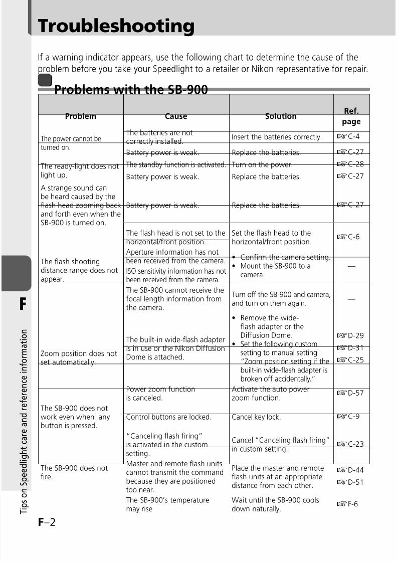
8/8/2019 SB 900 Manual
http://slidepdf.com/reader/full/sb-900-manual 118/142

8/8/2019 SB 900 Manual
http://slidepdf.com/reader/full/sb-900-manual 119/142
F–3
F
T i p s o n
S p e e d l i g h t c a r e a n d r e f e r e n c e i n f o r m a t i o n
Warning indicators
Warning indicator Cause SolutionRef.
page
“Battery Power Weak”
indicator appears.
All operations have stoppeddue to low battery power.
Replace the batteries. kC-27
Warning beeps sound and
warning icon appears when
the camera’s shutter release
button is pressed.The SB-900’s temperaturerises and the SB-900 may bedamaged.
Wait until the SB-900 coolsdown naturally.
kF-6
“Thermal Cut-out” indicator
appears.
All operations have stoppedbecause the SB-900’stemperature has risenand the SB-900 may bedamaged.
Wait until the SB-900 coolsdown naturally.
kF-6
“Safety circuit activation”
indicator appears.
All functions other than the
power switch are inoperablebecause of powerabnormalities.
Turn off the power, remove
the batteries, and contactyour retailer or Nikonrepresentative.
—
The ready-light blinks
after firing.
Underexposure may haveoccurred even with the flashfiring at maximum output.
Use a wider aperture ormove closer to the subjectand reshoot.
kD-4kD-7kD-10kD-13kD-42
Warning beeps sound for
approx. three seconds in the
remote flash unit.
Underexposure may haveoccurred even with the flash
firing at maximum output.
Use a wider aperture,move closer to the subjector change the position
of the remote flash unitand reshoot.
kD-42
“Filter detection failure”
indicator appears.
The attached color filter hasnot been detected.
Confirm whether the colorfilter is correctly attached.
kD-34
The lens aperture is beyondflash distance range.
Reset the aperture. —
The lens aperture is not setat minimum.
Set the apertureto minimum.
—
The camera is turned off. Turn the camera on. —

8/8/2019 SB 900 Manual
http://slidepdf.com/reader/full/sb-900-manual 120/142
F–4
F
T i p s o n
S p e e d l i g h t c a r e a n d r e f e r e n c e i n f o r m a t i o n
Troubleshooting
If the built-in wide-flash adapter is broken off accidentally
The wide-flash adapter may break if subjected to a strong shock while on the
flash head.In this case, contact your retailer or Nikon representative.
When the wide-flash adapter is broken off, it is no longer possible to set the
zoom position to the desired position. To adjust the zoom position, go to the
custom setting “Zoom position setting if the built-in wide-flash adapter is
broken off accidentally” (kC-25).
Microcomputer characteristics
The SB-900 incorporates a microcomputer to control flash operations. In rare cases,
the SB-900 may not work properly even after fresh batteries are properly installed.
If this happens, replace the batteries while the SB-900 is turned on.
•
•
•

8/8/2019 SB 900 Manual
http://slidepdf.com/reader/full/sb-900-manual 121/142
F–5
F
T i p s o n
S p e e d l i g h t c a r e a n d r e f e r e n c e i n f o r m a t i o n
Notes on continuous flash shooting
To prevent the SB-900 from overheating, allow the SB-900 to cool down for at least
10 minutes after the maximum number of continuous firings have been performed
as shown in the table below.
Setting the “Thermal Cut-out” function is recommended. (k
F-6)•
Maximum number of continuous firings
Flash modeMax. number of continuous
firings (at 6 frames/sec.)
i-TTL
Non-TTL auto
Manual flash mode (flash output level: M1/1, M1/2)
•
•
•
15 or less
Manual flash mode (flash output level: M1/4 to M1/128)• 40 or less
Do not exceed the maximum number of continuous firings,as this may cause the SB-900 to overheat or degrade.
"WARNING
v Notes for battery temperatureWhile operating continuous flash shooting, batteries may also generate heat.
When replacing batteries after continuous flash shooting, note not to get burned.

8/8/2019 SB 900 Manual
http://slidepdf.com/reader/full/sb-900-manual 122/142
F–6
F
T i p s o n
S p e e d l i g h t c a r e a n d r e f e r e n c e i n f o r m a t i o n
Thermal Cut-out
Low
The SB-900 features thermal cut-out, which offers protection against raised operating temperature.
This feature is controlled from the Custom Settings menu. (kC-24)
The selected setting is shown by an icon.
Thermal Cut-out: OnThe temperature of the SB-900 is shown in three stages.
If the temperature of the unit rises as a result of the flash being fired multiple
times in quick succession, a warning will be displayed and the SB-900 will
enter protective shutdown mode.
Temperature warning indicators
•
•
•
•
■
High
Thermal Cut-out: Off
The temperature of the SB-900 is shown in three stages.
If the temperature of the unit rises as a result of the flash being fired
multiple times in quick succession, a warning icon will be displayed. If sound
is turned on, a warning beep will sound each time the camera shutter-
release button is pressed.
Temperature warning indicators
•
•
■
Wait until the SB-900 cools down.
Operation can be resumed once the warning is no longer displayed.
•
•
Low High
Stop firing and wait until the SB-900 cools down.
Operation can be resumed once the warning is no longer displayed.
•
•
8/8/2019 SB 900 Manual
http://slidepdf.com/reader/full/sb-900-manual 123/142
F–7
F
T i p s o n
S p e e d l i g h t c a r e a n d r e f e r e n c e i n f o r m a t i o n
Tips on Speedlight care
Cleaning
Use a blower brush to remove dirt and dust from the SB-900 and clean it with a
soft, clean cloth. After using the SB-900 near saltwater, wipe the flash unit with
a soft, clean cloth moistened slightly with plain water to remove the salt, then
dry it using a dry cloth.On rare occasions, the LCD may turn on or go dark, due to static electricity. This
is not a malfunction. The display will soon return to normal.
Do not drop the SB-900 or hit it against a hard surface, as this may damage its
precision mechanisms. Do not apply strong pressure to the LCD panel.
Storage
Store the SB-900 in a cool, dry place to prevent malfunctions due to high
humidity, as well as the growth of mold or mildew.
Keep the SB-900 away from chemicals such as camphor or naphthalene. Avoid
exposing the SB-900 to magnetic waves from TVs or radios.
Do not use or leave the SB-900 in locations subject to high temperatures such as
those encountered near a heater or stove, as this may cause damage.
When not using the SB-900 for more than two weeks, be sure to remove the
batteries to prevent malfunctions due to battery leakage.
Take the SB-900 out once a month, insert the batteries, and fire the unit several
times to reform the capacitor.
Operating location
An extreme temperature change can cause condensation to form inside the
SB-900. When subjecting the SB-900 to sudden and extreme temperature
changes, place it inside an airtight container such as plastic bag. Leave it
inside the container for a while before exposing it gradually to the outside
temperature.
Avoid exposing the SB-900 to strong magnetism or radio waves from TVs or
high-voltage power transmission towers, as this may cause it to malfunction.
•
•
•
•
•
•
•
•
•
•
Never use thinner, benzene, or other activeagents when cleaning the Speedlight,as this may damage the Speedlight or cause it to catch
on fire. Using these agents may also impair your health.
"WARNING #

8/8/2019 SB 900 Manual
http://slidepdf.com/reader/full/sb-900-manual 124/142
F–8
F
T i p s o n
S p e e d l i g h t c a r e a n d r e f e r e n c e i n f o r m a t i o n
Notes on batteries
Suitable batteries
Use four AA-type batteries of any of the following types:
Alkaline-manganese (1.5V) batteriesLithium (1.5V) batteries
Oxyride™ (1.5V) batteriesNi-MH (1.2V) batteries
High-power manganese batteries are not recommended.
Depending on battery specifications, when batteries become hot, the SB-900’s
safety circuits are activated, cutting off power. This often occurs when the flash
unit is operated in the repeating flash mode. Battery power will recover when
the temperature returns to normal.
Be sure to read the user’s manuals for your rechargeable batteries and batterycharger for detailed information on how to handle and recharge the batteries.
Never attempt to charge batteries that are not rechargeable batteries, as they
could explode.
Notes on handling batteries
Because flash consumes a large amount of battery power, batteries may not
operate properly before reaching the end of their stated lifespan or the number
of charges/discharges as specified by the battery manufacturer.When replacing batteries, replace all four batteries at the same time. Do not mix
battery types or brands or use old with new batteries.
When installing batteries, turn off the power of the Speedlight and never
reverse the polarity of the batteries.
If the battery terminals become soiled, remove dirt and smudges before use, as
this may cause malfunction.
Battery power tends to weaken as the temperature drops. It also gradually
decreases when batteries are not used for a long time and recovers after a shortbreak following intensive use. Be sure to check battery power and replace the
batteries with fresh ones if you notice any delays in the recycling time.
Do not store batteries in locations subject to high temperatures and high humidity.
••
••
•
•
•
•
•
•
•
•
•
•
To protect the environment, do not disposeof used rechargeable batteries yourself.Instead, take these batteries to your nearest
recycling center.
Recycling rechargeablebatteries
Ni-MH
8/8/2019 SB 900 Manual
http://slidepdf.com/reader/full/sb-900-manual 125/142
F–9
F
T i p s o n
S p e e d l i g h t c a r e a n d r e f e r e n c e i n f o r m a t i o n
About the LCD panel
Characteristics of the LCD panel
Due to the directional characteristics of LCDs, the LCD panel is difficult to read
when viewed from above. However, it can be seen clearly from a somewhatlower angle.
The LCD panel becomes darker at high temperatures (approx. 60°C/140°F), but
returns to normal at normal temperatures (20°C/68°F).
The LCD’s response time slows down at low temperatures (approx. 5°C/41°F and
below), but returns to normal at normal temperatures (20°C/68°F).
LCD panel illuminator ON/OFF
Press any button on the SB-900 to turn the illuminator on (when the SB-900 poweris on) and make the LCD panel easier to read.
The illuminator goes off if the SB-900 is not operated for 16 seconds.
To cancel the LCD panel illumination, go to the custom setting (kC-24) and
turn it off.
Even if the LCD panel illuminator is set to OFF, the SB-900’s LCD panel
illuminator turns on when the camera’s control panel illuminator is turned on.
The LCD panel illuminator also lights up when the custom setting is displayed.
Adjusting the LCD panel’s contrast
The contrast of the LCD panel can be adjusted in the custom setting (kC-25).
There are nine contrast levels.
•
•
•
•
•
•
•
8/8/2019 SB 900 Manual
http://slidepdf.com/reader/full/sb-900-manual 126/142
F–10
F
T i p s o n
S p e e d l i g h t c a r e a n d r e f e r e n c e i n f o r m a t i o n
Updating firmware
The latest Nikon firmware can be downloaded from Nikon’s website.
Firmware is updated through the camera.
For users in the U.S.A.:
http://www.nikonusa.com/
For users in Europe:
http://www.europe-nikon.com/support
For users in Asia, Oceania, the Middle East, and Africa:
http://www.nikon-asia.com/
Additional information may be available from the Nikon representative in your
area. See the URL below for contact information:
http://nikonimaging.com/
D3*1, D700
Cameras compatible with SB-900 firmware update
*1 D3 camera with either firmware A or firmware B version 2.00 or later.
See the custom setting section to determine which version of firmware you areusing (kC-25).
If your camera is not compatible with firmware updates, please contact a Nikon
representative in your area.
•
•
•
•
•
•
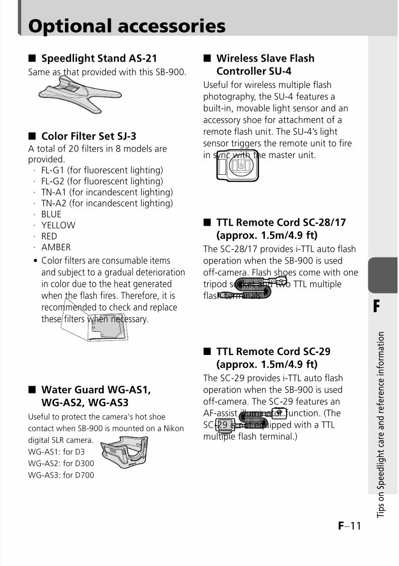
8/8/2019 SB 900 Manual
http://slidepdf.com/reader/full/sb-900-manual 127/142
F–11
F
T i p s o n
S p e e d l i g h t c a r e a n d r e f e r e n c e i n f o r m a t i o n
Speedlight Stand AS-21
Same as that provided with this SB-900.
Color Filter Set SJ-3A total of 20 filters in 8 models areprovided.
FL-G1 (for fluorescent lighting)FL-G2 (for fluorescent lighting)TN-A1 (for incandescent lighting)TN-A2 (for incandescent lighting)BLUEYELLOWREDAMBER
Color filters are consumable itemsand subject to a gradual deteriorationin color due to the heat generated
when the flash fires. Therefore, it isrecommended to check and replacethese filters when necessary.
Water Guard WG-AS1,WG-AS2, WG-AS3
Useful to protect the camera's hot shoe
contact when SB-900 is mounted on a Nikon
digital SLR camera.
WG-AS1: for D3
WG-AS2: for D300
WG-AS3: for D700
■
■
········
•
■
Wireless Slave FlashController SU-4
Useful for wireless multiple flash
photography, the SU-4 features abuilt-in, movable light sensor and an
accessory shoe for attachment of a
remote flash unit. The SU-4’s light
sensor triggers the remote unit to fire
in sync with the master unit.
TTL Remote Cord SC-28/17(approx. 1.5m/4.9 ft)
The SC-28/17 provides i-TTL auto flash
operation when the SB-900 is used
off-camera. Flash shoes come with one
tripod socket and two TTL multiple
flash terminals.
TTL Remote Cord SC-29(approx. 1.5m/4.9 ft)
The SC-29 provides i-TTL auto flash
operation when the SB-900 is used
off-camera. The SC-29 features an
AF-assist illuminator function. (The
SC-29 is not equipped with a TTL
multiple flash terminal.)
■
■
■
Optional accessories
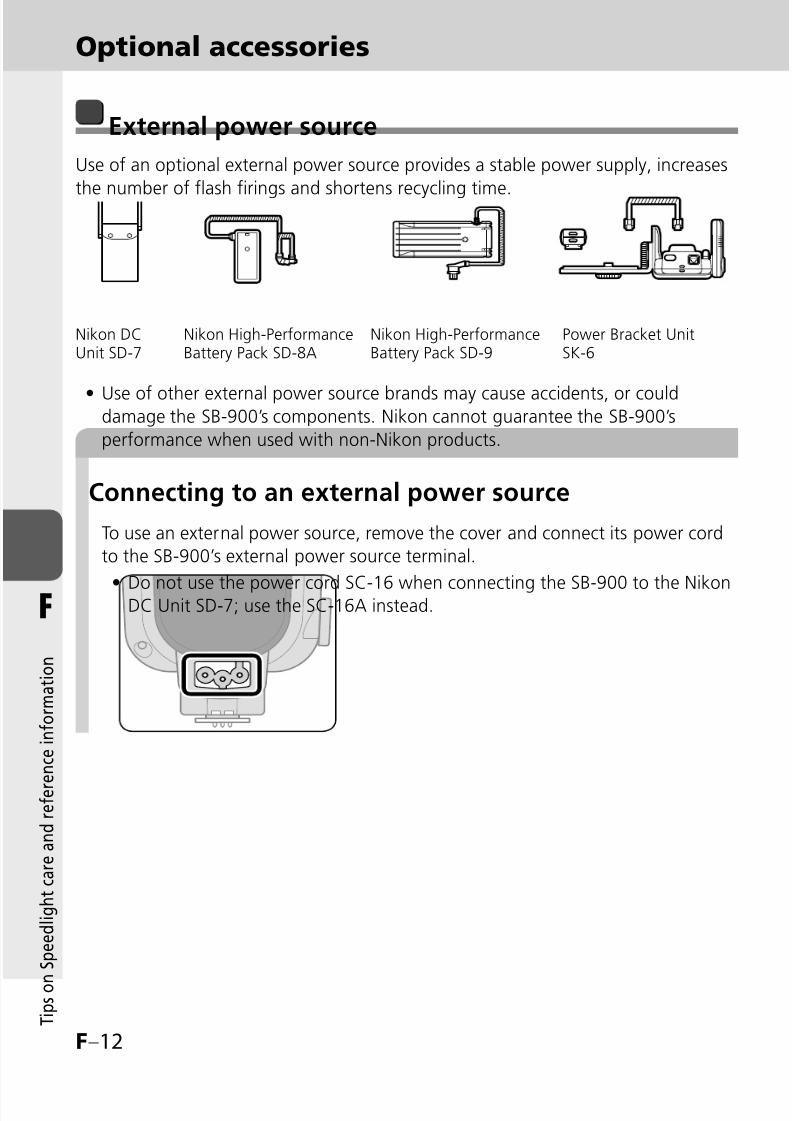
8/8/2019 SB 900 Manual
http://slidepdf.com/reader/full/sb-900-manual 128/142
F–12
F
T i p s o n
S p e e d l i g h t c a r e a n d r e f e r e n c e i n f o r m a t i o n
External power source
Use of an optional external power source provides a stable power supply, increases
the number of flash firings and shortens recycling time.
Use of other external power source brands may cause accidents, or coulddamage the SB-900’s components. Nikon cannot guarantee the SB-900’s
performance when used with non-Nikon products.
•
Optional accessories
Connecting to an external power source
To use an external power source, remove the cover and connect its power cord
to the SB-900’s external power source terminal.
Do not use the power cord SC-16 when connecting the SB-900 to the NikonDC Unit SD-7; use the SC-16A instead.•
Nikon DCUnit SD-7
Nikon High-PerformanceBattery Pack SD-8A
Nikon High-PerformanceBattery Pack SD-9
Power Bracket UnitSK-6
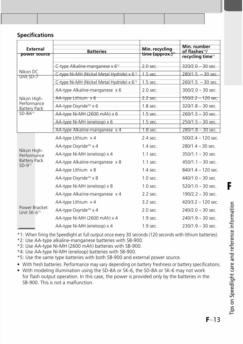
8/8/2019 SB 900 Manual
http://slidepdf.com/reader/full/sb-900-manual 129/142
F–13
F
T i p s o n
S p e e d l i g h t c a r e a n d r e f e r e n c e i n f o r m a t i o n
Externalpower source
BatteriesMin. recyclingtime (approx.)*1
Min. numberof flashes*1/recycling time*1
Nikon DCUnit SD-7
C-type Alkaline-manganese x 6*2 2.0 sec. 320/2.0 – 30 sec.
C-type Ni-MH (Nickel Metal Hydride) x 6*3 1.5 sec. 280/1.5 – 30 sec.
C-type Ni-MH (Nickel Metal Hydride) x 6*4 1.5 sec. 260/1.5 – 30 sec.
Nikon High-PerformanceBattery PackSD-8A*5
AA-type Alkaline-manganese x 6 2.0 sec. 300/2.0 – 30 sec.
AA-type Lithium x 6 2.2 sec. 550/2.2 – 120 sec.
AA-type OxyrideTM x 6 1.8 sec. 320/1.8 – 30 sec.
AA-type Ni-MH (2600 mAh) x 6 1.5 sec. 260/1.5 – 30 sec.
AA-type Ni-MH (eneloop) x 6 1.5 sec. 250/1.5 – 30 sec.
Nikon High-PerformanceBattery PackSD-9*5
AA-type Alkaline-manganese x 4 1.8 sec. 280/1.8 – 30 sec.
AA-type Lithium x 4 2.4 sec. 500/2.4 – 120 sec.
AA-type OxyrideTM x 4 1.4 sec. 280/1.4 – 30 sec.
AA-type Ni-MH (eneloop) x 4 1.1 sec. 350/1.1 – 30 sec
AA-type Alkaline-manganese x 8 1.1 sec. 450/1.1 – 30 sec.
AA-type Lithium x 8 1.4 sec. 840/1.4 – 120 sec.
AA-type OxyrideTM x 8 1.0 sec. 440/1.0 – 30 sec.
AA-type Ni-MH (eneloop) x 8 1.0 sec. 520/1.0 – 30 sec.
Power BracketUnit SK-6*5
AA-type Alkaline-manganese x 4 2.2 sec. 190/2.2 – 30 sec.
AA-type Lithium x 4 3.2 sec. 420/3.2 – 120 sec.
AA-type OxyrideTM x 4 2.0 sec. 240/2.0 – 30 sec.
AA-type Ni-MH (2600 mAh) x 4 1.9 sec. 240/1.9 – 30 sec.
AA-type Ni-MH (eneloop) x 4 1.9 sec. 230/1.9 – 30 sec.
*1: When firing the Speedlight at full output once every 30 seconds (120 seconds with lithium batteries).
*2: Use AA-type alkaline-manganese batteries with SB-900.*3: Use AA-type Ni-MH (2600 mAh) batteries with SB-900.*4: Use AA-type Ni-MH (eneloop) batteries with SB-900.*5: Use the same type batteries with both SB-900 and external power source.
With fresh batteries. Performance may vary depending on battery freshness or battery specifications.With modeling illumination using the SD-8A or SK-6, the SD-8A or SK-6 may not workfor flash output operation. In this case, the power is provided only by the batteries in theSB-900. This is not a malfunction.
••
Specifications

8/8/2019 SB 900 Manual
http://slidepdf.com/reader/full/sb-900-manual 130/142
F–14
F
T i p s o n
S p e e d l i g h t c a r e a n d r e f e r e n c e i n f o r m a t i o n
Specifications
Electronic constructionAutomatic Insulated Gate Bipolar Transistor (IGBT) andseries circuitry
Guide number (at 35 mm zoomposition, in FX-format, standardillumination pattern, 20°C/68°F)
34/111.5 (ISO 100, m/ft), 48/157.5 (ISO 200, m/ft)
Flash shooting distance range(TTL auto flash/Auto Apertureflash/Non-TTL auto flash)
0.6 m to 20 m (2 to 66 ft.) (varies depending on camera'simage area setting, illumination pattern, ISO sensitivity, zoomposition, and lens aperture in use)
Illumination pattern
There are three types of llumination pattern: standard, evenand center-weightedThe light distribution angle is automatically adjusted to thecamera’s image area in both FX and DX formats
Available flash mode
TTLAuto Aperture flashNon-TTL auto flashDistance-priority manual flashManual flashRepeating flash
••••••
Other available functionsTest firing, monitor pre-flashes, AF-assist illuminator, andModeling illuminator
Nikon Creative Lighting
System
A variety of flash operations are available with compatiblecameras: i-TTL mode, Advanced Wireless Lighting, FV Lock
flash, Flash color information communication, Auto FP High-Speed sync, and Wide-area AF-Assist Illuminator
Multiple flash operationAdvanced Wireless LightingSU-4 type wireless multiple flash
••
Flash exposure control set onthe camera
Camera’s sync. modes: Slow-sync, Red-eye reduction in slow-sync, Front-curtain sync, Rear-curtain sync, Rear-curtail slow-syncShooting functions: Auto FP High-Speed sync, FV Lock flash
Bounce capability
Flash head tilts down to -7° or up to 90° with click-stops at -7°,
0°, 45°, 60°, 75°, 90°Flash head rotates horizontally 180° to the left and right withclick-stops at 0°, 30°, 60°, 90°, 120°, 150°, 180°
Power ON/OFFRotate the Power ON-OFF switch to turn the SB-900 on or offStandby function can be set
Power source
Use four AA-type batteries of any of the following types:Alkaline-manganese (1.5V) batteriesLithium (1.5V) batteriesOxyride
TM(1.5V) batteries
Ni-MH (1.2V) batteriesFor minimum number of flashes and recycling time of eachbattery, see F-21.
•••
•

8/8/2019 SB 900 Manual
http://slidepdf.com/reader/full/sb-900-manual 131/142

8/8/2019 SB 900 Manual
http://slidepdf.com/reader/full/sb-900-manual 132/142
F–16
F
T i p s o n
S p e e d l i g h t c a r e a n d r e f e r e n c e i n f o r m a t i o n
Specifications
In FX-format, standard illumination pattern■
ISO sensitivity Zoom position (mm)
6400 3200 1600 800 400 200 100 14BA/
WP14BA 14WP 17 18 20 24 28 35 50 70 85 105 120 135 180 200
A p e r t u r e
2.8 2 1.42.3-
20
2.9-
20
3.1-
20
3.9-
20
3.9-
20
4.3-
20
4.8-
20
5.2-
20
5.9-
20
7-
20
7.8-
20
8.3-
20
8.8-
20
9-
20
9-
20
9.5-
20
9.9-
20
F l a s h s h o o t i n g d i s t a n c e r a n g e ( m
)
4 2.8 21.7-
20
2-
20
2.2-
20
2.8-
20
2.8-
20
3-
20
3.4-
20
3.7-
20
4.2-
20
4.9-
20
5.5-
20
5.9-
20
6.2-
20
6.4-
20
6.4-
20
6.8-
20
7-
20
5.6 4 2.8 2 1.41.2-
18
1.5-
20
1.5-
20
2-
20
2-
20
2.2-
20
2.4-
20
2.6-
20
2.9-
20
3.5-
20
3.9-
20
4.2-
20
4.4-
20
4.5-
20
4.5-
20
4.8-
20
4.9-
20
8 5.6 4 2.8 2 1.40.9-
13
1-
16
1.1-
17
1.4-
20
1.4-
20
1.5-
20
1.7-
20
1.9-
20
2.1-
20
2.5-
20
2.8-
20
2.9-
20
3.1-
20
3.2-
20
3.2-
20
3.4-
20
3.5-
20
11 8 5.6 4 2.8 2 1.4
0.6
-9.2
0.8
-11.3
0.8
-12
1
-15
1
-15
1.1
-17
1.2
-19
1.3
-20
1.5
-20
1.8
-20
2
-20
2.1
-20
2.2
-20
2.3
-20
2.3
-20
2.4
-20
2.5
-20
16 11 8 5.6 4 2.8 20.6
-6.5
0.6-8
0.6-
8.5
0.7-
11
0.7-
11
0.8-
12
0.9-
13
1-
14
1.1-
16
1.3-
19
1.4-
20
1.5-
20
1.6-
20
1.6-
20
1.6-
20
1.7-
20
1.8-
20
22 16 11 8 5.6 4 2.80.6
-4.6
0.6-
5.6
0.6-6
0.6-
7.7
0.6-
7.7
0.6-
8.5
0.6-
9.5
0.7-
10
0.8-
11
0.9-
13
1-
15
1.1-
16
1.1-
17
1.2-
18
1.2-
18
1.2-
19
1.3-
19
32 22 16 11 8 5.6 40.6
-3.2
0.6-4
0.6-
4.2
0.6-
5.5
0.6-
5.5
0.6-6
0.6-
6.7
0.6-
7.3
0.6-
8.2
0.7-
9.8
0.7-
11
0.8-
11
0.8-
12
0.8-
12
0.8-
12
0.9-
13
0.9-
13
32 22 16 11 8 5.60.6
-2.3
0.6-
2.8
0.6-3
0.6-
3.8
0.6-
3.8
0.6-
4.2
0.6-
4.7
0.6-
5.1
0.6-
5.8
0.6-
6.4
0.6-
7.7
0.6-
8.2
0.6-
8.7
0.6-9
0.6-9
0.6-
9.5
0.7-
9.8
32 22 16 11 8 0.6-1.6
0.6-2
0.6-2.1
0.6-2.7
0.6-2.7
0.6-3
0.6-3.3
0.6-3.6
0.6-4.1
0.6-4.8
0.6-5.5
0.6-5.8
0.6-6.1
0.6-6.3
0.6-6.3
0.6-6.7
0.6-6.9
32 22 16 110.6
-1.1
0.6-
1.4
0.6-
1.5
0.6-
1.9
0.6-
1.9
0.6-
2.1
0.6-
2.3
0.6-
2.5
0.6-
2.9
0.6-
3.4
0.6-
3.8
0.6-
4.1
0.6-
4.3
0.6-
4.5
0.6-
4.5
0.6-
4.7
0.6-
4.9
32 22 160.6
-0.8
0.6-1
0.6-1
0.6-
1.3
0.6-
1.3
0.6-
1.5
0.6-
1.6
0.6-
1.8
0.6-2
0.6-
2.4
0.6-
2.7
0.6-
2.9
0.6-3
0.6-
3.1
0.6-
3.1
0.6-
3.3
0.6-
3.4
32 22 0.60.6
-0.7
0.6-
0.7
0.6-
0.9
0.6-
0.9
0.6-1
0.6-
1.1
0.6-
1.2
0.6-
1.4
0.6-
1.7
0.6-
1.9
0.6-2
0.6-
2.1
0.6-
2.2
0.6-
2.2
0.6-
2.3
0.6-
2.4
32 0.6 0.6 0.6 0.6 0.60.6
-
0.7
0.6-
0.8
0.6-
0.9
0.6-
1
0.6-
1.2
0.6-
1.3
0.6-
1.4
0.6-
1.5
0.6-
1.5
0.6-
1.5
0.6-
1.6
0.6-
1.7BA: With the Nikon Diffusion Dome attached
WP: With the wide-flash adapter in place
•
•
Flash shooting distance range (for i-TTL auto flash,Auto Aperture flash and Non-TTL auto flash mode)
The flash shooting distance range of the SB-900 is between 0.6 m and 20 m (2.0 ft.and 65.6 ft.). The flash shooting distance range differs depending on the camera’simage area, illumination pattern, ISO sensitivity, zoom position and flash output level.
The following table is for FX-format and standard illumination pattern.
The flash shooting distance range for each setting can be seen in the LCD display (kC-11).
•
•

8/8/2019 SB 900 Manual
http://slidepdf.com/reader/full/sb-900-manual 133/142
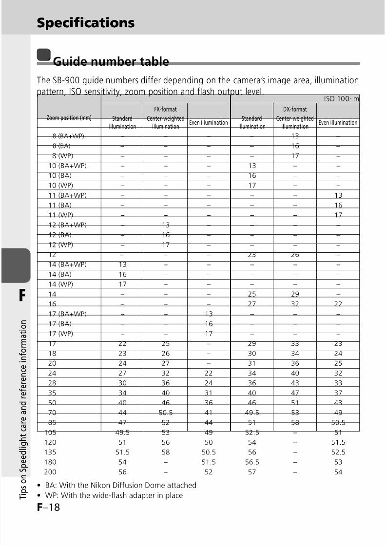
8/8/2019 SB 900 Manual
http://slidepdf.com/reader/full/sb-900-manual 134/142
F–18
F
T i p s o n
S p e e d l i g h t c a r e a n d r e f e r e n c e i n f o r m a t i o n
Specifications
Zoom position (mm)
FX-format DX-format
Standardillumination
Center-weightedillumination
Even illuminationStandard
illuminationCenter-weighted
illuminationEven illumination
8 (BA+WP) – – – – 13 –
8 (BA) – – – – 16 –
8 (WP) – – – – 17 –
10 (BA+WP) – – – 13 – –
10 (BA) – – – 16 – –
10 (WP) – – – 17 – –
11 (BA+WP) – – – – – 13
11 (BA) – – – – – 16
11 (WP) – – – – – 17
12 (BA+WP) – 13 – – – –
12 (BA) – 16 – – – –
12 (WP) – 17 – – – –
12 – – – 23 26 –
14 (BA+WP) 13 – – – – –
14 (BA) 16 – – – – –
14 (WP) 17 – – – – –14 – – – 25 29 –
16 – – – 27 32 22
17 (BA+WP) – – 13 – – –
17 (BA) – – 16 – – –
17 (WP) – – 17 – – –
17 22 25 – 29 33 23
18 23 26 – 30 34 24
20 24 27 – 31 36 25
24 27 32 22 34 40 32
28 30 36 24 36 43 3335 34 40 31 40 47 37
50 40 46 36 46 51 43
70 44 50.5 41 49.5 53 49
85 47 52 44 51 58 50.5
105 49.5 53 49 52.5 – 51
120 51 56 50 54 – 51.5
135 51.5 58 50.5 56 – 52.5
180 54 – 51.5 56.5 – 53
200 56 – 52 57 – 54
BA: With the Nikon Diffusion Dome attached
WP: With the wide-flash adapter in place
•
•
ISO 100· m
Guide number table
The SB-900 guide numbers differ depending on the camera’s image area, illumination
pattern, ISO sensitivity, zoom position and flash output level.
Specifications
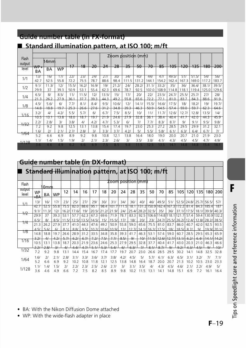
8/8/2019 SB 900 Manual
http://slidepdf.com/reader/full/sb-900-manual 135/142
F–19
F
T i p s o n
S p e e d l i g h t c a r e a n d r e f e r e n c e i n f o r m a t i o n
Standard illumination pattern, at ISO 100; m/ft■
Guide number table (in FX-format)
BA: With the Nikon Diffusion Dome attached
WP: With the wide-flash adapter in place
•
•
Guide number table (in DX-format)
Standard illumination pattern, at ISO 100; m/ft■
Flashoutputlevel
Zoom position (mm)
14mm17 18 20 24 28 35 50 70 85 105 120 135 180 200WP +
BABA WP
1/113/ 42.7
16/ 52.5
17/ 55.8
22/ 72.2
23/ 75.5
24/ 78.7
27/ 88.6
30/ 98.4
34/ 111.5
40/ 131.2
44/ 144.1
47/ 154.2
49.5/ 162.4
51/ 167.3
51.5/ 169.0
54/ 117.2
56/ 183.7
1/29.1/ 29.9
11.3/ 37
12/ 39.3
15.5/ 50.9
16.2/ 53.1
16.9/ 55.4
19/ 62.3
21.2/ 69.6
24/ 78.7
28.2/ 92.5
31.1/ 102.0
33.2/ 108.9
35/ 114.8
36/ 118.1
36.4/ 119.4
38.1/ 125.0
39.5/ 129.6
1/46.5/ 21.3
8/ 26.2
8.5/ 27.9
11/ 36.1
11.5/ 37.7
12/ 39.3
13.5/ 44.3
15/ 49.2
17/ 55.8
20/ 65.6
22/ 72.2
23.5/ 77.1
24.7/ 81.0
25.5/ 83.7
25.7/ 84.3
27/ 88.6
28/ 91.9
1/84.5/ 14.8
5.6/ 18.8
6/ 19.7
7.7/ 25.3
8.1/ 26.6
8.4/ 27.6
9.5/ 31.2
10.6/ 34.8
12/ 39.3
14.1/ 46.3
15.5/ 50.9
16.6/ 54.5
17.5/ 57.4
18/ 59.0
18.2/ 59.7
19/ 62.3
19.7/ 64.6
1/163.2/ 10.5
4/ 13.1
4.2/ 13.8
5.5/ 18.0
5.7/ 18.7
6/ 19.7
6.7/ 21.9
7.5/ 24.6
8.5/ 27.9
10/ 32.8
11/ 36.1
11.7/ 38.4
12.6/ 40.4
12.7/ 41.7
12.8/ 42.0
13.5/ 44.3
14/ 45.9
1/32 2.2/ 7.2
2.8/ 9.2
3/ 9.8
3.8/ 12.5
4/ 13.1
4.2/ 13.8
4.7/ 15.4
5.3/ 17.4
6/ 19.7
7/ 23.0
7.7/ 25.3
8.3/ 27.2
8.7/ 28.5
9/ 29.5
9.1/ 29.9
9.5/ 31.2
9.8/ 32.1
1/641.6/ 5.2
2/ 6.6
2.1/ 6.9
2.7/ 8.9
2.8/ 9.2
3/ 9.8
3.3/ 10.8
3.7/ 12.1
4.2/ 13.8
5/ 16.4
5.5/ 18.0
5.8/ 19.0
6.1/ 20.0
6.3/ 20.7
6.4/ 21.0
6.7/ 21.9
7/ 23.0
1/1281.1/ 3.6
1.4/ 4.6
1.5/ 4.9
1.9/ 6.2
2/ 6.6
2.1/ 6.9
2.3/ 7.5
2.6/ 8.5
3/ 9.8
3.5/ 11.5
3.8/ 12.5
4.1/ 13.5
4.3/ 14.1
4.5/ 14.8
4.5/ 14.8
4.7/ 15.4
4.9/ 16.1
Flashoutputlevel
Zoom position (mm)10mm
12 14 16 17 18 20 24 28 35 50 70 85 105 120 135 180 200WP+BA
BA WP
1/113/ 42.7
16/ 52.5
17/ 55.8
23/ 75.5
25/ 82.0
27/ 88.6
29/ 95.1
30/ 98.4
31/ 101.7
34/ 111.5
36/ 18.1
40/ 131.2
46/ 150.9
49.5/ 162.4
51/ 167.3
52.5/ 172.2
24.8/ 81.4
25.7/ 84.3
56.5/ 185.4
57/ 187
1/29.1/ 29.9
11.3/ 37
12/ 39.3
16.2/ 53.1
17.6/ 57.7
19/ 62.3
20.5/ 67.3
21.2/ 69.6
21.9/ 71.9
24/ 78.7
25.4/ 83.3
28.2/ 92.5
32.5/ 106.6
35/ 114.8
36/ 118.1
37.1/ 121.7
17.5/ 57.4
18.1/ 59.4
39.9/ 130.9
40.3/ 132.2
1/46.5/ 21.3
8/ 26.2
8.5/ 27.9
11.5/ 37.7
12.5/ 41.0
13.5/ 44.3
14.5/ 47.6
15/ 49.2
15.5/ 50.9
17/ 55.8
18/ 59.0
20/ 65.6
23/ 75.5
24.7/ 81.0
25.5/ 83.7
26.2/ 86.0
12.4/ 40.7
12.8/ 42.0
28.2/ 92.5
28.5/ 93.5
1/84.5/ 14.8
5.6/ 18.8
6/ 19.7
8.1/ 26.6
8.8/ 28.9
9.5/ 31.2
10.2/ 33.5
10.6/ 34.8
10.9/ 35.8
12/ 39.3
12.7/ 41.7
14.1/ 46.3
16.2/ 53.1
17.5/ 57.4
18/ 59.0
18.5/ 60.7
8.7/ 28.5
9/ 29.5
19.9/ 65.3
20.1/ 65.9
1/163.2/
10.5
4/
13.1
4.2/
13.8
5.7/
18.7
6.2/
20.3
6.7/
21.9
7.2/
23.6
7.5/
24.6
7.7/
25.3
8.5/
27.9
9/
29.5
10/
32.8
11.5/
37.7
12.6/
40.4
12.7/
41.7
13.1/
43.0
6.2/
20.3
6.4/
21.0
14.1/
46.3
14.2/
46.6
1/322.2/ 7.2
2.8/ 9.2
3/ 9.8
4/ 13.1
4.4/ 14.4
4.7/ 15.4
5.1/ 16.7
5.3/ 17.4
5.4/ 17.7
6/ 19.7
6.3/ 20.7
7/ 23.0
8.1/ 26.6
8.7/ 28.5
9/ 29.5
9.2/ 30.2
4.3/ 14.1
4.5/ 14.8
9/ 32.5
10/ 32.8
1/641.6/ 5.2
2/ 6.6
2.1/ 6.9
2.8/ 9.2
3.1/ 10.2
3.3/ 10.8
3.6/ 11.8
3.7/ 12.1
3.8/ 12.5
4.2/ 13.8
4.5/ 14.8
5/ 16.4
5.7/ 18.7
6.1/ 20.0
6.3/ 20.7
6.5/ 21.3
3.1/ 10.2
3.2/ 10.5
7/ 23.0
7.1/ 23.3
1/1281.1/ 3.6
1.4/ 4.6
1.5/ 4.9
2/ 6.6
2.2/ 7.2
2.3/ 7.5
2.5/ 8.2
2.6/ 8.5
2.7/ 8.9
3/ 9.8
3.1/ 10.2
3.5/ 11.5
4/ 13.1
4.3/ 14.1
4.5/ 14.8
4.6/ 15.1
2.1/ 6.9
2.2/ 7.2
4.9/ 16.1
5/ 16.4
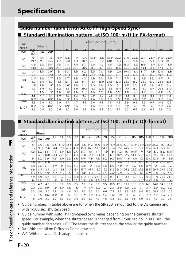
8/8/2019 SB 900 Manual
http://slidepdf.com/reader/full/sb-900-manual 136/142
F–20
F
T i p s o n
S p e e d l i g h t c a r e a n d r e f e r e n c e i n f o r m a t i o n
Guide number table (with Auto FP High-Speed Sync)
Standard illumination pattern, at ISO 100; m/ft (in FX-format)■
Standard illumination pattern, at ISO 100; m/ft (in DX-format)■
Guide numbers in tables above are for when the SB-900 is mounted to the D3 camera and
with 1/500 sec. shutter speed.
Guide number with Auto FP High-Speed Sync varies depending on the camera’s shutter
speed. For example, when the shutter speed is changed from 1/500 sec. to 1/1000 sec., the
guide number decreases 1 EV. The faster the shutter speed, the smaller the guide number.
BA: With the Nikon Diffusion Dome attached
WP: With the wide-flash adapter in place
•
•
•
•
Specifications
Flashoutputlevel
Zoom position (mm)
14mm17 18 20 24 28 35 50 70 85 105 120 135 180 200WP +
BABA WP
1/16/
19.77.4/ 24.3
7.8/ 25.6
10.1/ 33.1
10.6/ 34.8
11/ 36.1
12.4/ 40.7
13.8/ 45.3
15.6/ 51.2
18.4/ 6.04
20.2/ 66.3
21.6/ 70.9
22.8/ 74.8
23.4/ 76.8
23.7/ 77.6
24.8/ 81.4
25.7/ 84.3
1/24.2/ 13.8
5.2/ 17.1
5.5/ 18.0
7.1/ 23.3
7.4/ 24.3
7.7/ 25.3
8.7/ 28.5
9.7/ 31.8
11/ 36.1
13/ 42.7
14.2/ 46.6
15.2/ 49.9
16.1/ 52.8
16.5/ 54.1
16.7/ 54.8
17.5/ 57.4
18.1/ 59.4
1/43/ 9.8
3.7/ 12.1
3.9/ 12.8
5/ 16.4
5.3/ 17.4
5.5/ 18.0
6.2/ 20.3
6.9/ 22.6
7.8/ 25.6
9.2/ 30.2
10.1/ 33.1
10.8/ 35.4
11.4/ 37.4
11.7/ 38.4
11.8/ 38.7
12.4/ 40.7
12.8/ 42.0
1/82.1/ 6.9
2.6/ 8.5
2.7/ 8.9
3.5/ 11.5
3.7/ 12.1
3.8/ 12.5
4.3/ 14.1
4.8/ 15.7
5.5/ 18.0
6.5/ 21.3
7.1/ 22.3
7.6/ 24.9
8/ 26.2
8.2/ 26.9
8.3/ 27.2
8.7/ 28.5
9/ 29.5
1/161.5/ 4.9
1.8/ 5.9
1.9/ 6.2
2.5/ 8.2
2.6/ 8.5
2.7/ 8.9
3.1/ 10.2
3.4/ 11.2
3.9/ 22.8
4.6/ 15.1
5/ 16.4
5.4/ 17.7
5.7/ 18.7
5.8/ 19.0
5.9/ 19.4
6.2/ 20.3
6.4/ 21.0
1/32 1/ 3.3
1.3/ 4.7
1.3/ 4.7
1.7/ 5.6
1.8/ 5.9
1.9/ 6.2
2.1/ 6.9
2.4/ 7.9
2.7/ 8.9
3.2/ 10.5
3.5/ 11.5
3.8/ 12.5
4/ 13.1
4.1/ 13.5
4.1/ 13.5
4.3/ 14.1
4.5/ 14.8
1/640.7/ 2.3
0.9/ 3.0
0.9/ 3.0
1.2/ 3.9
1.3/ 4.7
1.3/ 4.7
1.5/ 4.9
1.7/ 5.6
1.9/ 6.2
2.3/ 7.5
2.5/ 8.2
2.7/ 8.9
2.8/ 9.2
2.9/ 9.5
2.9/ 9.5
3.1/ 10.2
3.2/ 10.5
1/1280.5/ 1.6
0.6/ 2.0
0.6/ 2.0
0.8/ 2.6
0.9/ 3.0
0.9/ 3.0
1/ 3.3
1.2/ 3.9
1.3/ 4.7
1.6/ 5.2
1.7/ 5.6
1.9/ 6.2
2/ 6.6
2/ 6.6
2/ 6.6
2.1/ 6.9
2.2/ 7.2
Flashoutput
level
Zoom position (mm)
10mm
12 14 16 17 18 20 24 28 35 50 70 85 105 120 135 180 200WP+BA BA WP
1/16/
19.77.4/ 24.3
7.8/ 25.6
10.5/ 34.4
11.5/ 37.7
12.4/ 40.7
13.3/ 43.6
13.8/ 45.3
14.2/ 46.6
15.6/ 51.2
16.5/ 54.1
18.4/ 6.04
21.1/ 69.2
22.7/ 74.5
23.4/ 76.8
24.1/ 79.1
24.8/ 81.4
25.7/ 84.3
26/ 85.3
26.2/ 86.0
1/24.2/ 13.8
5.2/ 17.1
5.5/ 18.0
7.4/ 24.3
8.1/ 26.6
8.7/ 28.5
9.4/ 30.8
9.7/ 31.8
10/ 32.8
11/ 36.1
11.6/ 38.0
13/ 42.7
14.9/ 48.9
16/ 52.5
16.5/ 54.1
17/ 55.8
17.5/ 57.4
18.1/ 59.4
18.3/ 60.0
18.5/ 60.7
1/43/ 3.7/ 3.9/ 5.2/ 5.7/ 6.2/ 6.6/ 6.9/ 7.1/ 7.8/ 8.2/ 9.2/ 10.5/ 11.3/ 11.7/ 12/ 12.4/ 12.8/ 13/ 13.1/
9.8 12.1 12.8 17.1 18.7 20.3 21.7 22.6 23.3 25.6 26.9 30.2 34.4 37.1 38.4 39.3 40.7 42.0 42.7 43.0
1/82.1/ 2.6/ 2.7/ 3.7/ 4/ 4.3/ 4.7/ 4.8/ 5/ 5.5/ 5.8/ 6.5/ 7.4/ 8/ 8.2/ 8.5/ 8.7/ 9/ 9.1/ 9.2/
6.9 8.5 8.9 12.1 13.1 14.1 15.4 15.7 16.4 18.0 19.0 21.3 24.3 26.2 26.9 27.9 28.5 29.5 29.9 30.2
1/161.5/ 1.8/ 1.9/ 2.6/ 2.8/ 3.1/ 3.3/ 3.4/ 3.5/ 3.9/ 4.1/ 4.6/ 5.2/ 5.6/ 5.8/ 6/ 6.2/ 6.4/ 6.5/ 6.5/
4.9 5.9 6.2 8.5 9.2 10.2 10.8 11.2 11.5 22.8 13.5 15.1 17.1 18.8 19.0 19.7 20.3 21.0 21.3 21.3
1/321/ 1.3/ 1.3/ 1.8/ 2/ 2.1/ 2.3/ 2.4/ 2.5/ 2.7/ 2.9/ 3.2/ 3.7/ 4/ 4.1/ 4.2/ 4.3/ 4.5/ 4.5/ 4.6/
3.3 4.7 4.7 5.9 6.6 6.9 7.5 7.9 8.2 8.9 9.5 10.5 12.1 13.1 13.5 13.8 14.1 14.8 14.8 15.1
1/640.7/ 0.9/ 0.9/ 1.3/ 1.4/ 1.5/ 1.6/ 1.7/ 1.7/ 1.9/ 2/ 2.3/ 2.6/ 2.8/ 2.9/ 3/ 3.1/ 3.2/ 3.2/ 3.2/
2.3 3.0 3.0 4.7 4.6 4.9 5.2 5.6 5.6 6.2 6.6 7.5 8.5 9.2 9.5 9.8 10.2 10.5 10.5 10.5
1/1280.5/ 0.6/ 0.6/ 0.9/ 1/ 1/ 1.1/ 1.2/ 1.2/ 1.3/ 1.4/ 1.6/ 1.8/ 2/ 2/ 2.1/ 2.1/ 2.2/ 2.2/ 2.3/
1.6 2.0 2.0 3.0 3.3 3.3 3.6 3.9 3.9 4.7 4.6 5.2 5.9 6.6 6.6 6.9 6.9 7.2 7.2 7.5

8/8/2019 SB 900 Manual
http://slidepdf.com/reader/full/sb-900-manual 137/142
F–21
F
T i p s o n
S p e e d l i g h t c a r e a n d r e f e r e n c e i n f o r m a t i o n
Batteries
Min. recycling
time (approx.)*
Min. number of flashes*/
recycling time*
Alkaline-manganese (1.5V) 4.0 sec. 110/4.0 – 30 sec.
Lithium (1.5V) 4.5 sec. 230/4.5 – 120 sec.
OxyrideTM (1.5V) 3.0 sec. 125/3.0 –30 sec.
Ni-MH (2600 mAh) 2.3 sec. 190/2.3 – 30 sec.
Ni-MH (eneloop) 2.3 sec. 165/2.3 – 30 sec.
* When firing the Speedlight at full output once every 30 seconds (120 seconds with lithium batteries).
While AF-assist illuminator, power zoom and LCD panel illumination are off.
With fresh batteries. Performance may vary depending on battery freshness or battery
specifications.
•
•
Min. number of flashes/recycling time of each battery
8/8/2019 SB 900 Manual
http://slidepdf.com/reader/full/sb-900-manual 138/142
F–22
F
T i p s o n
S p e e d l i g h t c a r e a n d r e f e r e n c e i n f o r m a t i o n
Refer to the “Speedlight parts” (kC-2) and “LCD panel” (kC-10) for each
part name and display indications.
•
Symbol
i-TTL Automatic Balanced Fill-Flash ...........D-2
i-TTL-compatible COOLPIX cameras ... B-2, E-3
i-TTL mode ..............................................D-2
A
Accessories .............................................F-11A collection of example photos ........ Separate
AF-Assist illuminator .......................B-3, D-58
AF-ILL ONLY...........................................D-59
Aperture ................................................D-23
Aperture value .......................................C-13
Auto aperture flash ..................................D-5
AUTO (auto) mode.................................D-51
Auto FP High-Speed Sync .......................D-55
B
Batteries ................................. C-4, C-27, F-8
Bounce-down flash ................................D-30
Bounce flash operation ..........................D-26
Built-in bounce card ...............................D-28
Built-in wide-flash adapter .....................D-31
CCanceling monitor pre-flashes ................D-52
Cancel receiving light from
other flash units .....................................C-18
Center-weighted illumination pattern ....D-24
Channel .................................................D-46
Close-up photography ...........................D-30
CLS ..........................................................A-3
CLS-compatible SLR cameras .................... B-2Color filters ............................................D-33
Color filter holder ..................................D-34
Color filter set .........................................F-11
Commander function.............................D-48
Continuous firing ......................................F-5
Control buttons .......................................C-8
COOLPIX cameras ............................. B-2, E-3
CPU Nikkor lenses ....................................A-3
Custom functions and settings ...............C-20
D
Default settings........................................A-3
Distance information..............................C-11
Distance priority manual flash ................D-11
DX-format ................................... C-23, D-62
E
Even illumination pattern .......................D-24
Exposure compensation .........................D-38
External power source .............................F-12
F
Filter detector ..........................................C-2
Flash color information communication .... B-3
Flash firing off..............................C-23, D-59Flash head ..................................... C-6, D-26
Flash head tilting/rotating lock
release button ........................... C-6, D-26
Flash mode ..............................................D-1
Flash mode icons ...................................C-10
Flash shooting distance range ................C-11
Flash shooting in Advanced
Wireless Lighting ...............................D-43
Flash output level ......................... D-18, D-23
Flash output level compensation ... C-13, D-37
Index
8/8/2019 SB 900 Manual
http://slidepdf.com/reader/full/sb-900-manual 139/142
F–23
F
T i p s o n
S p e e d l i g h t c a r e a n d r e f e r e n c e i n f o r m a t i o n
Flash output level compensation value ...D-37
Fluorescent filters ...................................D-33
Front-curtain sync ..................................D-56
Function button .....................................C-17
FX/DX selection ............................ C-23, D-62
FX-format .................................... C-23, D-62
FV Lock ..................................................D-55
G
Group ....................................................D-43
Groups of remote flash units..................D-43
Guide number .......................................D-22
Guide number table ................................F-18
H
Highlight................................................C-10
Highlight in the subject’s eyes ................D-28
I
Icons ......................................................C-10
Illumination pattern ..................... C-22, D-24
Incandescent filters ................................D-33
Included items .......................................A-14
Indication for insufficient light for
correct exposure .......D-4, D-7, D-10, D-13
ISO sensitivity ................................. A-3, C-11
ISO sensitivity factors .............................D-22
KKey lock ...................................................C-9
L
LCD panel .......................................C-10, F-9
LCD panel illuminator .....................C-24, F-9
Light distribution angle ..........................C-12
Light sensor for Non-TTL
auto flash .................................... D-5, D-8
Light sensor window for
wireless remote flash .........................D-40
Low battery power indicator ..................C-27
M
Manual mode ........................................D-14
MASTER....................................... D-45, D-50
Master flash unit ....................................D-39
Metering mode ........................................D-4
Min. number of flashes .................D-18, F-21
Min. recycling time ........................F-13, F-21
M (manual) mode ..................................D-51
MODE button ..........................................C-8
Modeling illuminator ..............................D-61
Monitor pre-flashes...................D-3, D-6, D-9
Mount pin ...............................................C-5
Mounting foot lock lever ..........................C-5
Multiple flash shooting ..........................D-39
My menu ...............................................C-26
NNikon Creative Lighting System (CLS) ....... B-3
Nikon Diffusion Dome............................D-29
Non-CLS-compatible cameras .................. E-2
Non-TTL auto flash......................... C-22, D-8
O
OK button ..................................... C-8, C-21
P
Power ON-OFF/wireless setting
switch ..............................C-8, D-45, D-50
Power zoom function .............................D-57
R
Ready-light .................................... C-7, D-42
Ready-light on the remote
flash unit ................................... C-2, D-42

8/8/2019 SB 900 Manual
http://slidepdf.com/reader/full/sb-900-manual 140/142
F–24
F
T i p s o n
S p e e d l i g h t c a r e a n d r e f e r e n c e i n f o r m a t i o n
Rear-curtain sync ...................................D-56
Recycling time ...............................D-18, F-21
Red-eye reduction ..................................D-56
Red-eye reduction with slow-sync flash ...D-56
REMOTE ...................................... D-45, D-50
Remote flash units .................................D-39
Repeating flash ...................C-22, D-17, D-49
Replacing batteries.................................C-27
Reset .....................................................C-25
S
SB-900 condition ...................................C-14
Selector dial ..................................... C-8, C-9
Setting the ISO sensitivity ............. C-24, D-60
Shooting distance ........................ C-11, D-23
Slow-sync flash ......................................D-55
Soft case ................................................A-14
Sound monitor.............................C-24, D-42
Speedlight stand ....................................D-41
Speedlight parts .......................................C-2
Standard illumination pattern .................D-24Standard i-TTL ..........................................D-2
Standby function .........................C-23, C-28
SU-4 type wireless multiple
flash shooting ..........................C-22, D-50
T
Table of flash shooting distance ranges ...F-16
Table of zoom positions ..........................F-17Test firing ..............................................D-60
Thermal Cut-out ............................. C-24, F-6
TTL Remote Cord ....................................F-11
Two-butoon reset ....................................C-9
U
Updating firmware..................................F-10
V
Value of underexposure at TTL ....... C-17, D-4
Version of firmware ...............................C-25
W
Warning indicators....................................F-3
Warranty card ........................................A-14
Water Guard ...........................................F-11
Wireless multiple flash shooting .............D-39
Wireless slave flash controller ..................F-11
ZZOOM button ..........................................C-8
Zoom position........................................D-57
Zoom position icons ...............................C-12
Index

8/8/2019 SB 900 Manual
http://slidepdf.com/reader/full/sb-900-manual 141/142
8/8/2019 SB 900 Manual
http://slidepdf.com/reader/full/sb-900-manual 142/142