satf 40mi satf 65mi satf 115mi - welding machine …
TRANSCRIPT

SATF – 40MI SATF – 65MI SATF – 115MI
User Instructions
The operator must read and keep this manual on its working station . this document is not contractual.
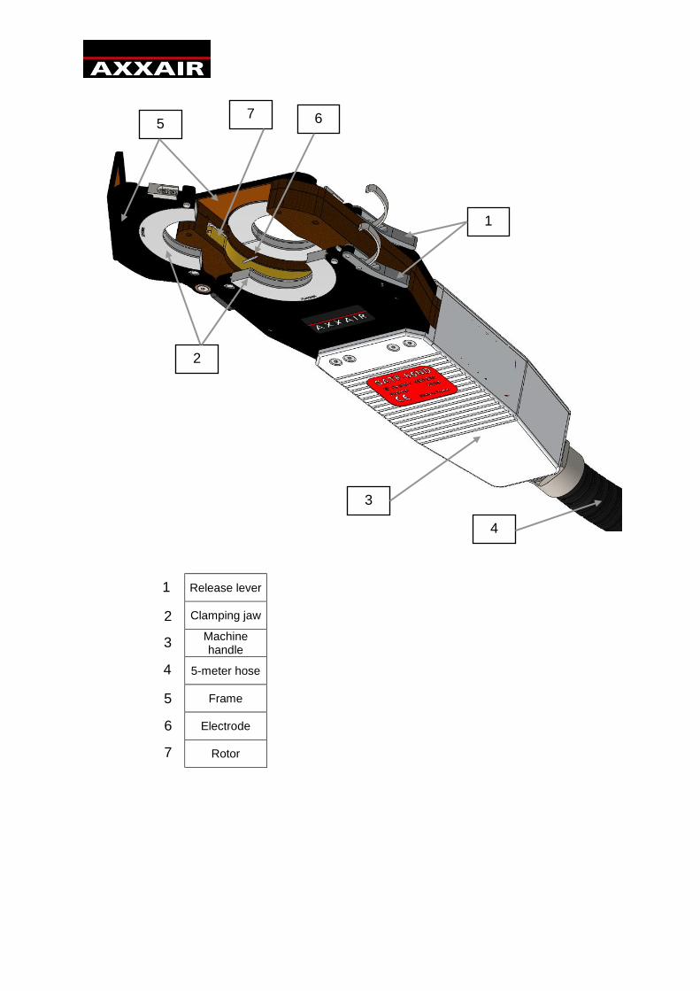
Release lever
Clamping jaw
Machine handle
5-meter hose
Frame
Electrode
Rotor
1
2
3
7
4
5 6
1
2
3
4
5
6
7
A mm
B mm
C mm
Ø min Ø max
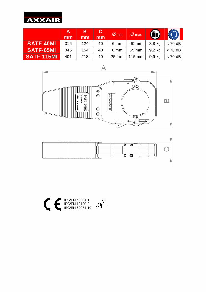
SATF-40MI 316 124 40 6 mm 40 mm 8,8 kg < 70 dB
SATF-65MI 346 154 40 6 mm 65 mm 9,2 kg < 70 dB
SATF-115MI 401 218 40 25 mm 115 mm 9,9 kg < 70 dB
IEC/EN 60204-1 IEC/EN 12100-2 IEC/EN 60974-10

User instructions :
General Safety Instructions :
WARNING! To avoid the risk of electric shock, injury or fire when using electrical equipment, follow the following basic safety instructions. Read and follow these instructions before using the machine. Keep these safety instructions in a safe place!
The operator should ensure his own safety and that of persons nearby when using AXXAIR welding equipment. Consult the regulations relating to operation of this type of equipment and workplace safety so that the appropriate safety measures can be taken.
Only qualified personnel may use this equipment; they must follow the operating instructions. Failure to implement these safety precautions can endanger the operator and damage the equipment.
Before using this type of equipment, the operator must be well-acquainted with turning on and operating this equipment as well as with the welding process. The operator must be aware of safety regulations in force. It is essential that the operator is aware of the location of the emergency shutoff switch.
Prior to each use, the operator must ensure that there are no personnel in the work zone and that all personnel (including the operator) present during arcing are wearing appropriate protective gear: safety goggles or protective helmet, flame-resistant clothing, protective gloves, etc. Avoid wearing loose-fitting clothing or personal accessories that can become tangled in the equipment.
There should be no draughts in the working area. A well-identified fire extinguisher must be located within easy reach of the equipment.
To avoid all risk of fire, do not leave flammable objects or products near the work station.
Before conducting maintenance operations, disconnect the electrical power supply. Maintenance of the electrical system must be performed by specially qualified and trained personnel.
DANGER. To avoid potential electrical shock that could lead to loss of life: obey all rules in force related to the installation and grounding of the equipment. Never touch live parts or electrodes with bare hands or wet gloves. Insulate yourself from the workpiece and from the ground.
Do not inhale gas and fumes emitted by the welding process.
Use ear protection or any other device to protect hearing.
WARN all nearby persons of the potential risks.
The operator must always use the recommended personal protective gear, safety goggles, gloves and flame-resistant clothing.
English

Warning:
Arc-welding can be dangerous for the operator as well as for all persons in the vicinity. Take all appropriate safety precautions before using the welding machine. Observe and obey the safety procedures imposed by your employer; these procedures should be based on the rules and regulations in force as well as on the manufacturer's recommendations.
Electric Shock = Potential loss of life.
Install and earth the welding equipment, following the rules and regulations in force.
Do not touch live parts. Do not touch electrodes with bare hands or wet gloves.
Insulate yourself from the ground and from the workpiece.
Ensure that the work position adopted is safe both for the operator and for persons nearby.
Fumes and gas = Potential health hazard:
Keep your face as far away from welding fumes as possible.
Provide ventilation and evacuation of welding fumes using a suitable device that provides asafe working environment.
Light rays from the arc = These can damage your eyes and burn your skin.
Protect your eyes and skin. Use a protective visor and wear safety clothing and protectivegloves.
Protect nearby persons from injury due to welding by providing protective curtains.
In the event of a malfunction, contact qualified service personnel only.
Contents
General Safety Instructions Warning 1. Declaration of conformity
2. Presentation 3. Machine handling and storage
Handling Storage Bench mounting
4. Connecting the weld head 5. Calibration 6. Mounting the clamping jaw 7. Electrode mounting 8. Remote pipe-electrode adjustment 9. Securing the pipe to be welded 10. Welding step-by-step
Preparing to weld Handling the pipe Welding
11. Welding machine maintenance
English

1. Declaration of conformity:
We certify that this product complies with the standards and regulations found on Page 3.
2. Presentation:
These machines are intended for closed-chamber weld head orbital TIG welding. This range of machines welds end-to-end pipe, elbow joints, pipe ferrules, T-joints, SMS connectors and other in a fully sealed inert environment. The weld heads are controlled by an AMI welding generator.
SATF-40MI SATF-65MI SATF-115MI Maximum welding current rating:
120 A
Maximum welding current for a 100% arc time factor:
60 A
Outside pipe diameter range:
Ø 3 mm to Ø 40 mm Ø 6 mm to Ø 65 mm Ø 25 mm to Ø 115 mm
Electrode diameter: 1.6 mm or 2.4 mm
Cooling unit: An external cooling unit is required when welding using these weld heads.
Operating temperature:
Ambient temperature must be within the range of 0 °C to +30 °C
3. Machine handling and storage:
Handling:
The SATF weld heads are portable devices that require no special handling (the heaviest weld head weighs less than 10 kg). However, standard precautions should be taken to avoid damaging the head and its hose during handing and transport.
Storage:
If the weld head is not going to be used for a long period of time, store it in its original packaging. Cleaning the head and emptying the coolant is recommended before repacking the weld head. Protect the weld head from corrosion. Place a desiccant in the container where the weld head is stored.
Bench mounting:
SATF weld heads are designed to be mounted on pipe or parts to be welded using the clamping jaw and the head's closing system. The device can also be bench mounted as a fixed welding station by securing it by the handle using a vice.
English
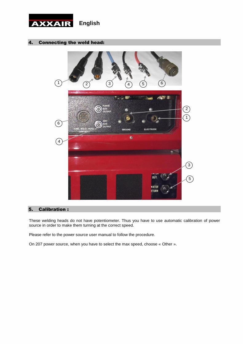
4. Connecting the weld head:
5. Calibration :
These welding heads do not have potentiometer. Thus you have to use automatic calibration of power source in order to make them turning at the correct speed.
Please refer to the power source user manual to follow the procedure.
On 207 power source, when you have to select the max speed, choose « Other ».
1
1
2
2
3
3
4
4
5
5
6
6
English

6. Mounting the clamping jaw:
SATF clamping jaws are designed for only one pipe diameter. These clamping jaws are made of stainless steel. The use of AXXAIR clamping jaws guarantees longevity of your weld head. Your warranty will be voided if you use clamps other than genuine AXXAIR clamps.
Note:
A clamping system consists of 4 parts. The operating diameter is engraved on the clamp.
The clamp is mounted without a wrench. Clamps are fastened on the external flanges and on the
frames and held in place by a straight fastener.
WARNING: SATF clamping jaws alone do not ensure pipe alignment and resistance to potential dilation linked to welding. To ensure perfect alignment after welding, you must make a preliminary tack weld on the work pieces.
English
To mount the clamping jaws, push on the button, put the clamping jaws and release the button.
7. Electrode mounting:
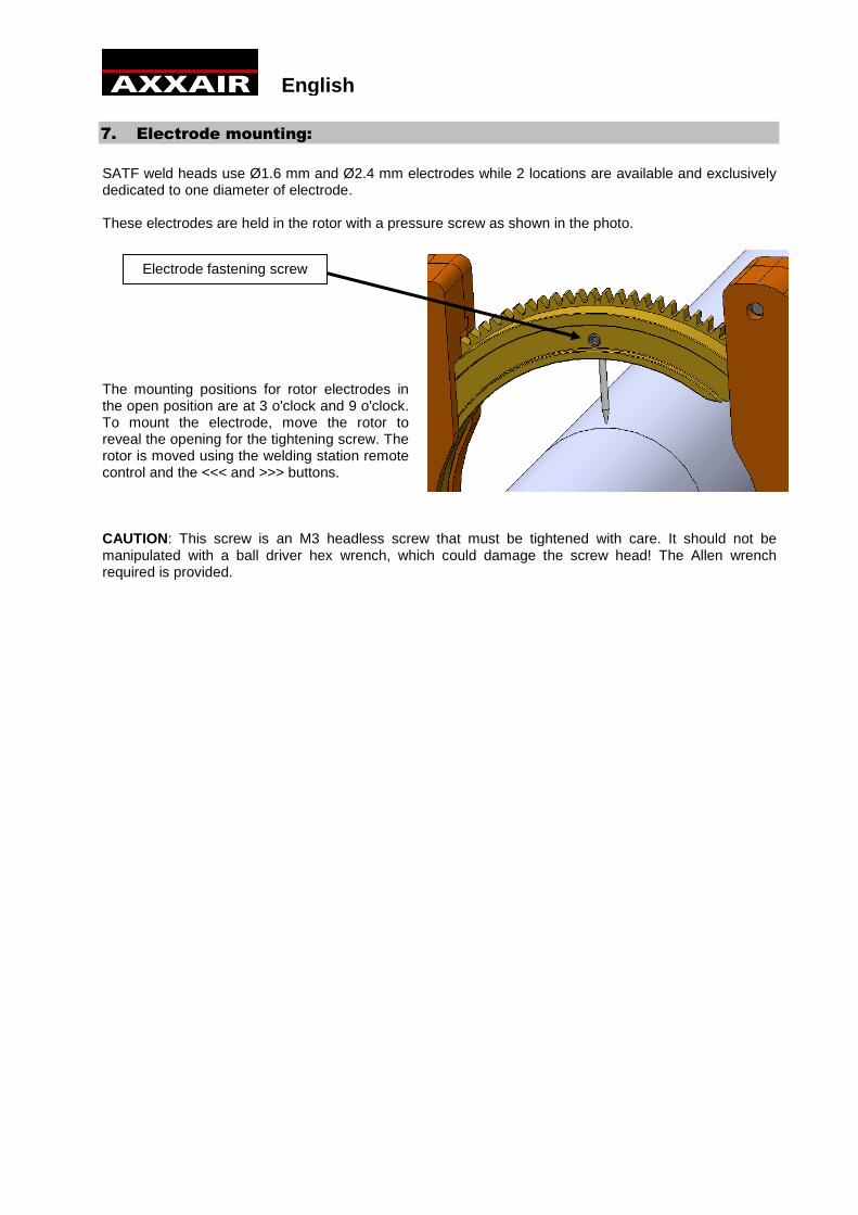
SATF weld heads use Ø1.6 mm and Ø2.4 mm electrodes while 2 locations are available and exclusively dedicated to one diameter of electrode.
These electrodes are held in the rotor with a pressure screw as shown in the photo.
The mounting positions for rotor electrodes in the open position are at 3 o'clock and 9 o'clock. To mount the electrode, move the rotor to reveal the opening for the tightening screw. The rotor is moved using the welding station remote control and the <<< and >>> buttons.
CAUTION: This screw is an M3 headless screw that must be tightened with care. It should not be manipulated with a ball driver hex wrench, which could damage the screw head! The Allen wrench required is provided.
Electrode fastening screw
English
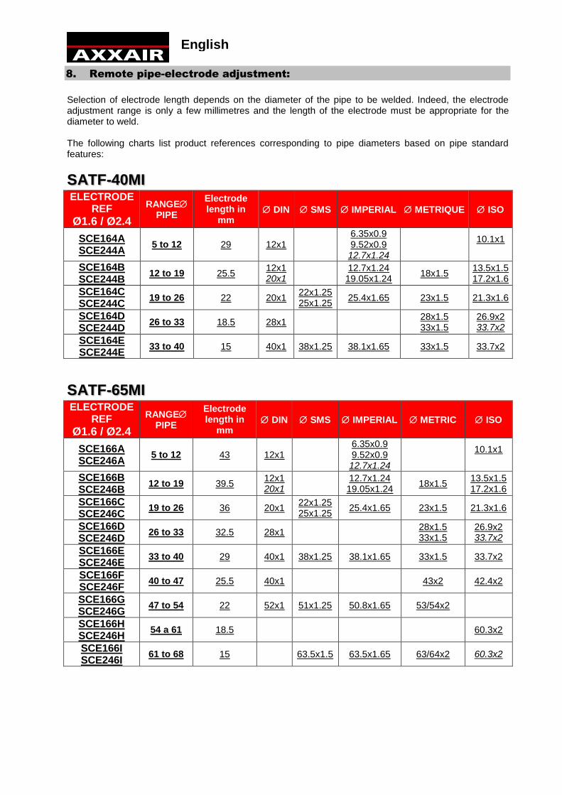
8. Remote pipe-electrode adjustment:
Selection of electrode length depends on the diameter of the pipe to be welded. Indeed, the electrode adjustment range is only a few millimetres and the length of the electrode must be appropriate for the diameter to weld.
The following charts list product references corresponding to pipe diameters based on pipe standard features:
SATF-40MI ELECTRODE
REF
Ø1.6 / Ø2.4
RANGE PIPE
Electrode length in
mm DIN SMS IMPERIAL METRIQUE ISO
SCE164A SCE244A
5 to 12 29 12x1 6.35x0.9 9.52x0.9 12.7x1.24
10.1x1
SCE164B SCE244B
12 to 19 25.5 12x1 20x1
12.7x1.24 19.05x1.24
18x1.5 13.5x1.5 17.2x1.6
SCE164C SCE244C
19 to 26 22 20x1 22x1.25 25x1.25
25.4x1.65 23x1.5 21.3x1.6
SCE164D SCE244D
26 to 33 18.5 28x1 28x1.5 33x1.5
26.9x2 33.7x2
SCE164E SCE244E
33 to 40 15 40x1 38x1.25 38.1x1.65 33x1.5 33.7x2
SATF-65MI ELECTRODE
REF
Ø1.6 / Ø2.4
RANGE PIPE
Electrode length in
mm DIN SMS IMPERIAL METRIC ISO
SCE166A SCE246A
5 to 12 43 12x1 6.35x0.9 9.52x0.9 12.7x1.24
10.1x1
SCE166B SCE246B
12 to 19 39.5 12x1 20x1
12.7x1.24 19.05x1.24
18x1.5 13.5x1.5 17.2x1.6
SCE166C SCE246C
19 to 26 36 20x1 22x1.25 25x1.25
25.4x1.65 23x1.5 21.3x1.6
SCE166D SCE246D
26 to 33 32.5 28x1 28x1.5 33x1.5
26.9x2 33.7x2
SCE166E SCE246E
33 to 40 29 40x1 38x1.25 38.1x1.65 33x1.5 33.7x2
SCE166F SCE246F
40 to 47 25.5 40x1 43x2 42.4x2
SCE166G SCE246G
47 to 54 22 52x1 51x1.25 50.8x1.65 53/54x2
SCE166H SCE246H
54 a 61 18.5 60.3x2
SCE166I SCE246I
61 to 68 15 63.5x1.5 63.5x1.65 63/64x2 60.3x2
English
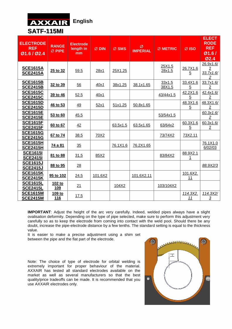
SATF-115MI
ELECTRODE REF
Ø1.6 / Ø2.4
RANGE
PIPE
Electrode length in
mm DIN SMS
IMPERIAL
METRIC ISO
ELECTRODE REF
Ø1.6 / Ø2.4
SCE1615A SCE2415A
25 to 32 59.5 28x1 25X1.25 25X1.5 28x1.5
26.7X1.65
26.9x1.6/2
33.7x1.6/2
SCE1615B SCE2415B
32 to 39 56 40x1 38x1.25 38.1x1.65 33x1.5 38X1.5
33.4X1.65
33.7x1.6/2
SCE1615C SCE2415C
39 to 46 52.5 40x1 43/44x1.5 42.2X1.6
5 42.4x1.6/
2
SCE1615D SCE2415D
46 to 53 49 52x1 51x1.25 50.8x1.65 48.3X1.6
5 48.3X1.6/
2
SCE1615E SCE2415E
53 to 60 45.5 53/54x1.5 60.3x1.6/
2
SCE1615F SCE2415F
60 to 67 42 63.5x1.5 63.5x1.65 63/64x2 60.3X1.6
5 60.3x1.6/
2
SCE1615G SCE2415G
67 to 74 38.5 70X2 73/74X2 73X2.11
SCE1615H SCE2415H
74 a 81 35 76.1X1.6 76.2X1.65 76.1X1.06/02/03
SCE1615I SCE2415I
81 to 88 31.5 85X2 83/84X2 88.9X2.1
1
SCE1615J SCE2415J
88 to 95 28 88.9X2/3
SCE1615K SCE2415K
95 to 102 24.5 101.6X2 101.6X2.11 101.6X2.
11
SCE1615L SCE2415L
102 to 109
21 104X2 103/104X2
SCE1615M SCE2415M
109 to 116
17.5 114.3X2.
11 114.3X2/
3
IMPORTANT: Adjust the height of the arc very carefully. Indeed, welded pipes always have a slight ovalisation deformity. Depending on the type of pipe selected, make sure to perform this adjustment very carefully so as to keep the electrode from coming into contact with the weld pool. Should there be any doubt, increase the pipe-electrode distance by a few tenths. The standard setting is equal to the thickness value. It is easier to make a precise adjustment using a shim set between the pipe and the flat part of the electrode.
Note: The choice of type of electrode for orbital welding is extremely important for proper behaviour of the material. AXXAIR has tested all standard electrodes available on the market as well as several manufacturers so that the best quality/price tradeoffs can be made. It is recommended that you use AXXAIR electrodes only.
English
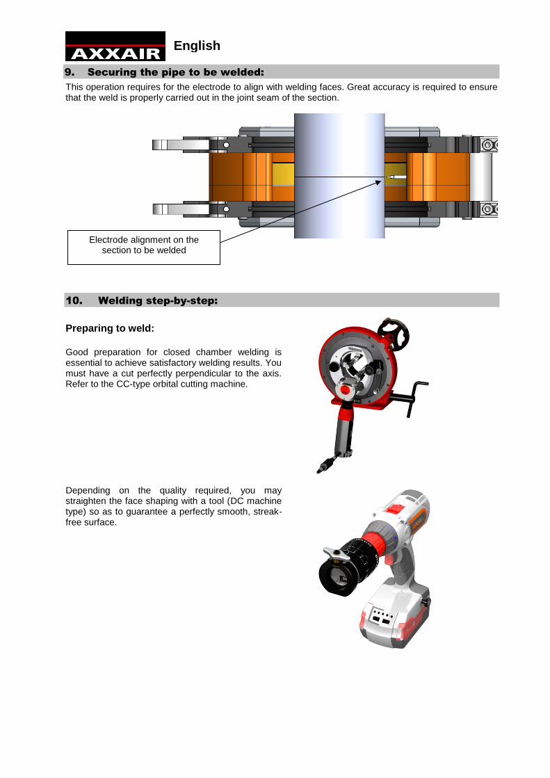
9. Securing the pipe to be welded:
This operation requires for the electrode to align with welding faces. Great accuracy is required to ensure that the weld is properly carried out in the joint seam of the section.
10. Welding step-by-step:
Preparing to weld:
Good preparation for closed chamber welding is essential to achieve satisfactory welding results. You must have a cut perfectly perpendicular to the axis. Refer to the CC-type orbital cutting machine.
Depending on the quality required, you may straighten the face shaping with a tool (DC machine type) so as to guarantee a perfectly smooth, streak-free surface.
Electrode alignment on the section to be welded
English

Handling the pipe:
CAUTION: SATF weld heads are attached to the pipe and support their own weight. Weld heads cannot withstand the alignment forces of long pipes. For length greater than 350 mm, you must tack weld the pipe or support pipe weight using alignment systems and not the weld head .
To ensure proper geometrical alignment it is recommended to manually tack weld the work pieces to be welded or use the weld head in tack weld operation mode.
Welding:
Welding is performed as follows:
Put the rotor in the open position:
Arranging the two pieces to be welded: close the frames using the toggle clamps and aligning the
electrode with the section to be welded.
Purge the system to evacuate oxygen in the hoses and in the weld head (do this when using the
system for the first time or when the system has not been in operation for a substantial period of
time).
Proceed with inertising the pipe (see the systems recommended by AXXAIR)
The welding starting position is the open rotor position.
Select the correct welding program.
The program selected must include a pre-gas period sufficiently long to fill the weld head:
approximately 20 to 30 seconds, depending on the weld head used, at a flow rate of 15/20 l/min.
Rotor open position
English

Reminder: Using closed chamber weld heads requires that the weld head is sufficiently filled with inert gas before starting to weld, i.e. before generating the arc. This is programmed into the welding station using the "Pre-Gas" function, which should be set to approximately 20 to 30 seconds with a flow rate of 15/20 l/min, depending on the dimension of the weld head used. In tack weld mode, you should open the head after each tack. To save time when working in tack weld mode, you can use a shorter pre-gas time, but remember to proceed to a fill purge of the weld head when making the first tack so as to obtain correct ignition.
11. Welding machine maintenance:
Before you use the machine each time, visually inspect the electric cords and water hose. Replace if necessary.
Maintenance operations should be performed by qualified personnel using authentic replacement
parts.
Before starting, disconnect all power supply sources.
The machine and accessories should always be stored and transported in their original
packaging.
It is essential to keep the machine clean to optimize performance.
It is essential that all foreign bodies are removed from the machine.
Inspect the condition of the rotor on the half collet. If need be, clean the surface using a red Scotch-brite pad.
It is essential to inspect the condition of the hose running from the weld head to the welding station to prevent water or gas leaks.
WARNING:
YOU MUST USE A COOLANT RECOMMENDED BY AXXAIR. NEVER ADD WATER TO THE COOLANT TANK BECAUSE THIS COULD CAUSE CHEMICAL REACTIONS THAT MAY DAMAGE THE MACHINE AND VOID THE WARRANTY!
English