satellite technology - imageevent
TRANSCRIPT
Satellite TechnologySatellite Technology
■ Assoc. Prof Dr Syed Idris Syed HassanAssoc. Prof Dr Syed Idris Syed Hassan■ School of Electrical and Electronic EngSchool of Electrical and Electronic Eng■ Universiti Sains MalaysiaUniversiti Sains Malaysia■ Seri Iskandar , 31750 PerakSeri Iskandar , 31750 Perak

ConceptConcept
Transponder
Earth station (site A) Earth station(site B)
IRRADIUM
downlinkdownlink
uplinkuplink
downlinkdownlink
uplinkuplink

ApplicationsApplications
■ Communication Communication (truncking call)(truncking call)
■ TeleconferenceTeleconference■ TelemedicineTelemedicine■ TV BroadcastingTV Broadcasting■ Data communicationData communication■ Telemetry(TEC, Telemetry(TEC,
remote sensing etc)remote sensing etc)
■ Weather telecastWeather telecast■ NavigationNavigation■ GPSGPS■ Security/Calamity Security/Calamity
monitoringmonitoring■ Standard TimeStandard Time■ militarymilitary

Type of SatellitesType of Satellites
■ LEO -Low Earth orbital 100-16,000Km LEO -Low Earth orbital 100-16,000Km (90min to 12hrs orbiting the earth)(90min to 12hrs orbiting the earth)
■ MEO - Medium Earth Orbital MEO - Medium Earth Orbital 16,000-36,000 Km (12 - 24 hrs orbiting 16,000-36,000 Km (12 - 24 hrs orbiting the earth)the earth)
■ GEO - Geosynchronous Earth Orbital - GEO - Geosynchronous Earth Orbital - 36,000 Km ( The satellite appears to be 36,000 Km ( The satellite appears to be stationary over one point on earth)stationary over one point on earth)

Look angle (Elevation)Look angle (Elevation)
)sin()sin()cos()cos()cos(cos
cos21.
tan
sin)(
2/12
seesse
s
e
s
es
LLllLL
r
r
r
rrdei
satelliteandstationearthbetweencedisdwhered
ElCos
+−=
−
+=
=
=
γ
γ
γ
ElEl

continuecontinue
■ Le = Earth station LatitudeLe = Earth station Latitude■ le = Earth station longitudele = Earth station longitude■ Ls = Satellite latitude ( = 0 for GEO)Ls = Satellite latitude ( = 0 for GEO)■ ls = Satellite longitudels = Satellite longitude■ rs = Satellite orbital radius ( ~ 36,000 km for GEO)rs = Satellite orbital radius ( ~ 36,000 km for GEO)■ re = earth radius = 6370 kmre = earth radius = 6370 km
For GEO satelliteFor GEO satellite
Cos Cos L Cos l le s eγ = −( ) ( )

Looking angle(azimuth)Looking angle(azimuth)
■ Consider for GEO onlyConsider for GEO only
( ) ( )( ) ( )α
γ
γ
=− −
− −
= − + +
−2
0 5
1tansin sin
sin sin
. ( )
s s L
s s l l
wheres l l L
e
e s
s e e
NN
SS
ESES
SatSat
EEWW
αα

continuecontinue
■ If Earth station is in the North Latitude ,If Earth station is in the North Latitude ,
the azimuth will be as follow (refer to N)the azimuth will be as follow (refer to N)
Satellite on the Eastof Earth station
Az=180-α
Satellite on the Westof Earth station
Az=180+α

continuecontinue
■ If the Earth station is in the South If the Earth station is in the South latitude , the azimuth will be (refer to N)latitude , the azimuth will be (refer to N)
Satellite on the Eastof Earth station
Az=α
Satellite on the Westof Earth station
Az=360-α

ExampleExample
Parameter MEASAT JCSAT Superb C
Longitude 91.5 E 128 E 144 E
EIRP (ku)54MHz 56.5 dBW 42 dBW 50.8 dBW
Beacon signal 6 Ghz ? 12.747ghzIf 1447.5MHz
12.255ghzif 955.0 Mhz
Vedio IF 980-1170 Mhz 950-1400mhz 1090-1433mhz
Looking anglefrom 100E 5N
El=78.05Az=216.5
El=55.9Az=108.4
El=37.7Az=100.3

Link budgetLink budget
Noise Power Budget for 54 MHz channelNoise Power Budget for 54 MHz channel
Boltzmann’s ConstantBoltzmann’s Constant = - 228.6 dBW/K/Hz= - 228.6 dBW/K/Hz
Receiving system noise temp.Receiving system noise temp. = 28.5 dBK= 28.5 dBK
Ku- Band ‘s channel bandwidthKu- Band ‘s channel bandwidth == 77.3 77.3 dBdB
Receiving noise level Receiving noise level - 122.8 - 122.8 dBdB
For C/N about 10 dB to allow rain and other fading For C/N about 10 dB to allow rain and other fading the signal level should be -112.8 dBthe signal level should be -112.8 dB

continuecontinue
( )C N
P G
kTB RG
EIRP
N LG
where
EIRP Equivalent isotropic radiated power P G
N ceived noise level kTB
L Path lossR
G ceiving antenna gain
R dis ce between earth station and satellite
wavelength of operating frequency
t tr
r pathr
t t
r
path
r
/
Re
Re
tan
=
=
= == =
= =
===
λπ
πλ
λ
4
4
2
2
continuecontinue
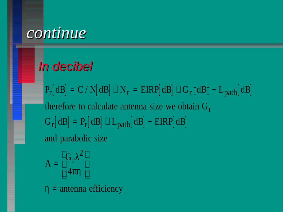
In decibelIn decibel
[ ] [ ] [ ] [ ]
[ ] [ ] [ ] [ ]
P dB C N dB N EIRP dB G dB L dB
therefore to calculate antenna size we obtain G
G dB P dB L dB EIRP dB
and parabolic size
AG
antenna efficiency
r r r path
r
r r path
r
= + = + −
= + −
=
=
/
λπη
η
2
4

ContinueContinue
■ Parabolic antenna diameterParabolic antenna diameter
π λπη
λ
π ηη
D G
DG
antenna efficiency
r
r
2 2
2
2
4 4
06
=
=
= = .

ContinueContinue
■ MEASATMEASAT
[ ] [ ] [ ]G dB C N dB N EIRP dB L dB
dB dB dB dB
dB
This gain can be achieved u g m diameter dish
r r path= + − +
= − − +=
/
. .
.
sin . ( ) .
10 122 8 56 5 205
35 7
0 75

continuecontinue
■ JCSATJCSAT
[ ] [ ] [ ]G dB C N dB N EIRP dB L dB
dB dB dB dB
dB
This gain can be achieved u g m diameter dish
r r path= + − +
= − − +=
/
.
.
sin . ( ) .
10 122 8 42 205
50 2
3 6

continuecontinue
■ Superbird CSuperbird C
[ ] [ ] [ ]G dB C N dB N EIRP dB L dB
dB dB dB dB
dB
This gain can be achieved u g m diameter dish
r r path= + − +
= − − +=
/
. .
.
sin . ( ) .
10 122 8 50 8 205
414
1 32
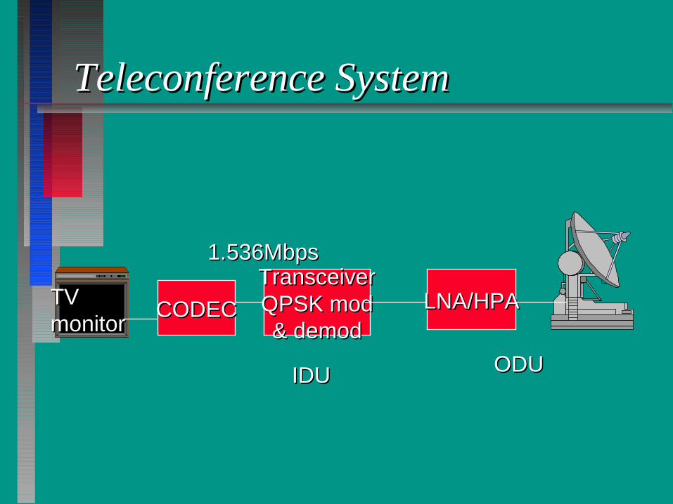
Teleconference SystemTeleconference System
LNA/HPALNA/HPATransceiverTransceiverQPSK modQPSK mod& demod& demod
CODECCODEC
1.536Mbps1.536Mbps
TVTVmonitormonitor
IDUIDU ODUODU

Data communicationData communication
LNA/HPALNA/HPATransceiverTransceiverQPSK modQPSK mod& demod& demod
1.536Mbps1.536MbpsPCPC
RouterRouter
&&TranscieverTransciever
IDUIDU ODUODU

Other factors need to considerOther factors need to consider
■ Antenna Antenna ■ Rain attenuationRain attenuation■ Beam FootprintBeam Footprint■ Mismatch lossesMismatch losses■ MisalignmentMisalignment■ Scintillation ~for low elevationScintillation ~for low elevation■ troposphere/atmospheretroposphere/atmosphere■ Bit error rateBit error rate

To avoid blockinguse offset antenna
no blocking
(6) Depointing error
Antenna gain will be reduced according to deviation from the true angle. Thisis given by
G dB G dBoe
db
( ) ( )= −
12
3
2θθ
where θe is the depointing error.therefore attenuation due to depointing error is
A dB e
dB
( )=
12
3
2θθ

Parabolic antenna feed
Horn a a
Le α b α bE R R
Le E
Ln Ln
E-plane Sectorial horn H-plane sectorial horn
a b
Le α1
α2
Ln
Primidal horn
L Re = 2λ L Rn = 3λ

Directivite gain
(I) E-plane sectorial
( ) ( )D
L L C x S x
xee n=
+322
2 2
πλ
C x t dtx
( ) cos( / )=∫ π20
2
S x t dtx
( ) sin( / )=∫ π20
2 and x= Le / 2λR
(ii) H-plane Sectorial
[ ] [ ]{ }DL R
LC x C x S x S xn
e
n
= − + −4
1 22
1 22π
λ ( ) ( ) ( ) ( )
xR
L
L
Rn
n1
1
2= +
/
/
/
/
λλ
λλ
xR
L
L
Rn
n2
1
2= −
/
/
/
/
λλ
λλ
(iii) Primidal horn
DL L
D Dpe n
e n=πλ2
32

* all the above horn antennas follow the following condition
( )D a D b
2 2 181 2 1 2 0
2 2
2
2
πσ λ π σσ
λ−
−
− − −
=
D is the desired directivitya,b are the dimension of the feeding waveguide
σλ
=Ls
( )L slant length of the horn
R L
s
e
=
= +2 22/
For large horn (assuming 50% efficiency)
Le = 2σλ L
D
Lne
= λπ
2
2
R L b LLe
se
= −
−( ) /
21 4
σ = D / .15 4

Scalar
Using circular waveguide. This type of feed is used for receiving antenna.It consists of 3 - 7 concentric rings of a quarter-wavelength broad.
feed
λ/ 4

Log periodic
Ln L1
α feed
dn
d1
First element
L F1 10 48=. λ where
FL
DL
D=
+1 and λ1
83 10=× fmin
D is the diameter of the first dipole = 2 a1
LD a=λ1
14 a1 is the radius of the first elementOther elements follow
( )aLL
Dn
n=2
; d Ln n= 2σ ; α τ
σ= −
−21
41tan
and τ= =+ +d
d
L
Ln
n
n
n
1 1
Gain(dB) 8.0 8.5 9.0 9.5 10.0 10.5 11.0 11.5 12.0σ 0.139 0.147 0.157 0.163 0.168 0.172 0.174 0.176 0.178τ 0.782 0.822 0.865 0.892 0.916 0.928 0.940 0.950 0.964

Helical antenna(Axial mode)
S
2r d
C = π d α
S
LDesign parameters2
33
2λ λ<<C
where C = π d2
33
2λ λ<<d
5 20o o<<α where α = helix angle
S = C Tan α and L = wire length per turn = C/cos αDirectivity
( )( )D n S C=152
λλ

Rain attenuationRain attenuation
1%1%
0.1%0.1%
0.01%0.01%
% of time exceedance% of time exceedance
2020 4040 6060 8080 100100mm/hrmm/hr
rain raterain rate

ContinueContinue
■ For TV and broadcasting usually the For TV and broadcasting usually the reliability is not very critical , so 99% is reliability is not very critical , so 99% is okay and this equivalent to 1% of okay and this equivalent to 1% of exceedance of timeexceedance of time
■ For data other digital com the reliability For data other digital com the reliability of 99.99% is probably chosen and this of 99.99% is probably chosen and this is equivalent to 0.01% of exceedance of is equivalent to 0.01% of exceedance of time.time.

continuecontinue
Att aR Lbpath= 0 01.
For 99.99% reliability, the attenuation is calculated asFor 99.99% reliability, the attenuation is calculated as
where a and b are constants relied on frequencywhere a and b are constants relied on frequency
RR0.01 0.01 rain rate at 0.01% of exceedance of timerain rate at 0.01% of exceedance of time
LLpath path is slant path where signal passed the rainis slant path where signal passed the rain

Slant pathSlant path
LLpathpath
RainRainheightheight~3km~3km

Footprints
Gs
Single beam θ3dB r=35,775 Km(3dB contour)
10o N footprint
d R=6378Km
10o S 20
d/2 = R sin 20 = 6378 X 0.3420 = 2181.4 Km
θ3dB = 2( ) = 2 ( ) = 2(arctan(0.060976))arctan arctan.
,
d
r2 21814
35 775
= 2 X 3.49o = 6.98o
( )G dBs =
× = =48360 0 65
6 98645 281
2.
..
For 12 Ghz ----> λ = 0.025 m
D mdB
= = × =70 70 0 025
6 980 251
3
λθ
.
..

Footprint can be stated in EIRP or power density flux (PDF) contours of3dB, 5dB etc.
eg
PDF (dBW/m2)=EIRP(dB) - Lp (dB)
where Lp is the propagation path loss (i.e ( )λπ42
r )
3dB contour
EIRP = Pt Gt = 56.5 dB therefore power transmitted=56.5 -28.1=26.4dBW
PFD = 56.5 - 205.1 = -148.6 dBW/m2
5dB contour
PDF= -148.6-2 = 150.6 dBW/m2
θ λ5
91 91 0 025
0 2519 06dB
o
D= = × =.
..

Elliptically shape beam
Usually using elliptically shape reflector
D2
D1
θ1
θ2
G dB31 2
48360= ηθθ
D11
70= λθ
D22
70= λθ
θ λ5
11
91dB D
= and θ λ5
22
91dB D
=

Array antennasAntenna array may consists of arrangement of dipoles , slots or patches insuch that a directive beam is formed.
θ d sinθ
1 d 2 3 N ( )( )E E e e eo
jkd j kd j N kd=+ + + +− − −−1 2 1sin sin sin. . . . . . .. . .θ θ θ
=
E N
No sin /
sin /
ϕϕ
2
2 where ϕ θ=kd sin
Radiation pattern (beam)main beam
θ λ3
102dB Nd=
in degrees
sidelobes

Changing the direction of the beam electronically
using phase shifter(parallel arangement)
θo
θο 2θο 3θο 4θο ....................Νθο
E EN
No
o
o=
−
−
sin
sin
ϕϕ
ϕϕ2
2 where ϕ θo okd=sin and d < 0.5 λ
θ λθ3
102dB
oNd≈
cos

(serial arrangement)
θο θο θο θο ....... .............θο
Using delay line
The serial phse shifter arrangement can be replaced by delay line in suchthat
ϕ θo okd kL= =sin where L is the electrical length of the delay line.

Implementation of multiple beam
1 2 3
amplifier amplifier amplifier
-ϕ1 ϕο +ϕ1 ϕο ϕο ϕο −ϕ1 ϕο +ϕ1
sum sum sum
beam 1 beam 2 beam 3eg. f = 12 Ghz then λ = 0.025 m , N = 20 d = 0.006mθο =0
θ λθ3
0102 102 0 025
20 0 006 021dB
oNd≈ = ×
×=
cos
.
. cos
θο=20
θ3102 0 025
20 0 006 2022 6dB
o≈ ××
=.
. cos.
θο=40
θ3102 0 025
20 0 006 4027 6dB
o≈ ××
=.
. cos.

Beam forming Network
Butler beam forming
1 2 3 4 5 6 7 8
-45o -45o -45o -45o
-67.5o -22.5o -22.5o -67.5o
1R 4L 3R 2L 2R 3L 4R 1L
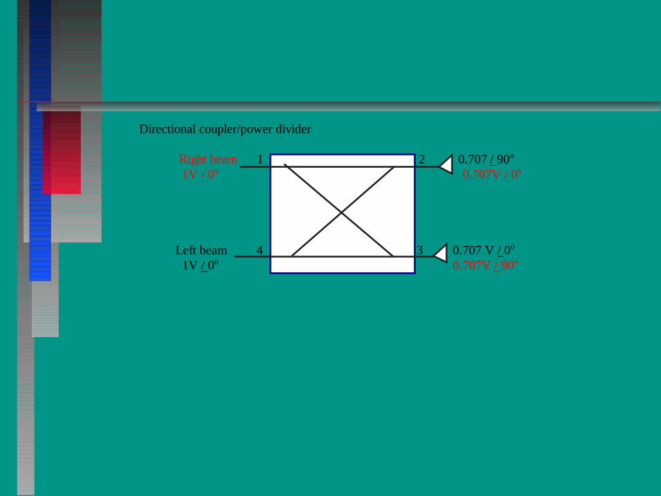
Directional coupler/power divider
Right beam 1 2 0.707 / 90o
1V / 0o 0.707V / 0o
Left beam 4 3 0.707 V / 0o
1V / 0o 0.707V / 90o